EP3593507B1 - System and method for beam management in high frequency multi-carrier operations with spatial quasi co-locations - Google Patents
System and method for beam management in high frequency multi-carrier operations with spatial quasi co-locations Download PDFInfo
- Publication number
- EP3593507B1 EP3593507B1 EP18777030.0A EP18777030A EP3593507B1 EP 3593507 B1 EP3593507 B1 EP 3593507B1 EP 18777030 A EP18777030 A EP 18777030A EP 3593507 B1 EP3593507 B1 EP 3593507B1
- Authority
- EP
- European Patent Office
- Prior art keywords
- carrier
- trp
- sqcl
- information
- reference signal
- Prior art date
- Legal status (The legal status is an assumption and is not a legal conclusion. Google has not performed a legal analysis and makes no representation as to the accuracy of the status listed.)
- Active
Links
- 238000000034 method Methods 0.000 title claims description 127
- 239000000969 carrier Substances 0.000 claims description 105
- 230000006854 communication Effects 0.000 claims description 102
- 238000004891 communication Methods 0.000 claims description 102
- 230000011664 signaling Effects 0.000 claims description 48
- 230000005540 biological transmission Effects 0.000 claims description 19
- 238000012545 processing Methods 0.000 description 29
- 238000010586 diagram Methods 0.000 description 15
- 238000005259 measurement Methods 0.000 description 9
- 230000007774 longterm Effects 0.000 description 5
- 238000010408 sweeping Methods 0.000 description 5
- 230000002776 aggregation Effects 0.000 description 4
- 238000004220 aggregation Methods 0.000 description 4
- 238000009826 distribution Methods 0.000 description 4
- 238000013507 mapping Methods 0.000 description 4
- 230000008901 benefit Effects 0.000 description 3
- 230000008569 process Effects 0.000 description 3
- 238000003491 array Methods 0.000 description 2
- 230000007175 bidirectional communication Effects 0.000 description 2
- 230000001413 cellular effect Effects 0.000 description 2
- 230000008859 change Effects 0.000 description 2
- 230000001186 cumulative effect Effects 0.000 description 2
- 238000005315 distribution function Methods 0.000 description 2
- 230000010354 integration Effects 0.000 description 2
- 238000004519 manufacturing process Methods 0.000 description 2
- 239000000203 mixture Substances 0.000 description 2
- 239000013307 optical fiber Substances 0.000 description 2
- 238000003860 storage Methods 0.000 description 2
- 230000004075 alteration Effects 0.000 description 1
- 230000009286 beneficial effect Effects 0.000 description 1
- 238000001514 detection method Methods 0.000 description 1
- 230000006870 function Effects 0.000 description 1
- 230000007246 mechanism Effects 0.000 description 1
- 230000003278 mimic effect Effects 0.000 description 1
- 238000006467 substitution reaction Methods 0.000 description 1
Images


Classifications
-
- H—ELECTRICITY
- H04—ELECTRIC COMMUNICATION TECHNIQUE
- H04W—WIRELESS COMMUNICATION NETWORKS
- H04W72/00—Local resource management
- H04W72/04—Wireless resource allocation
- H04W72/044—Wireless resource allocation based on the type of the allocated resource
- H04W72/046—Wireless resource allocation based on the type of the allocated resource the resource being in the space domain, e.g. beams
-
- H—ELECTRICITY
- H04—ELECTRIC COMMUNICATION TECHNIQUE
- H04L—TRANSMISSION OF DIGITAL INFORMATION, e.g. TELEGRAPHIC COMMUNICATION
- H04L5/00—Arrangements affording multiple use of the transmission path
- H04L5/003—Arrangements for allocating sub-channels of the transmission path
- H04L5/0048—Allocation of pilot signals, i.e. of signals known to the receiver
- H04L5/005—Allocation of pilot signals, i.e. of signals known to the receiver of common pilots, i.e. pilots destined for multiple users or terminals
-
- H—ELECTRICITY
- H04—ELECTRIC COMMUNICATION TECHNIQUE
- H04L—TRANSMISSION OF DIGITAL INFORMATION, e.g. TELEGRAPHIC COMMUNICATION
- H04L5/00—Arrangements affording multiple use of the transmission path
- H04L5/003—Arrangements for allocating sub-channels of the transmission path
- H04L5/0048—Allocation of pilot signals, i.e. of signals known to the receiver
- H04L5/0051—Allocation of pilot signals, i.e. of signals known to the receiver of dedicated pilots, i.e. pilots destined for a single user or terminal
-
- H—ELECTRICITY
- H04—ELECTRIC COMMUNICATION TECHNIQUE
- H04L—TRANSMISSION OF DIGITAL INFORMATION, e.g. TELEGRAPHIC COMMUNICATION
- H04L5/00—Arrangements affording multiple use of the transmission path
- H04L5/0091—Signaling for the administration of the divided path
- H04L5/0096—Indication of changes in allocation
- H04L5/0098—Signalling of the activation or deactivation of component carriers, subcarriers or frequency bands
-
- H—ELECTRICITY
- H04—ELECTRIC COMMUNICATION TECHNIQUE
- H04W—WIRELESS COMMUNICATION NETWORKS
- H04W56/00—Synchronisation arrangements
- H04W56/0005—Synchronisation arrangements synchronizing of arrival of multiple uplinks
-
- H—ELECTRICITY
- H04—ELECTRIC COMMUNICATION TECHNIQUE
- H04W—WIRELESS COMMUNICATION NETWORKS
- H04W56/00—Synchronisation arrangements
- H04W56/001—Synchronization between nodes
- H04W56/0015—Synchronization between nodes one node acting as a reference for the others
-
- H—ELECTRICITY
- H04—ELECTRIC COMMUNICATION TECHNIQUE
- H04W—WIRELESS COMMUNICATION NETWORKS
- H04W72/00—Local resource management
- H04W72/04—Wireless resource allocation
- H04W72/044—Wireless resource allocation based on the type of the allocated resource
- H04W72/0446—Resources in time domain, e.g. slots or frames
-
- H—ELECTRICITY
- H04—ELECTRIC COMMUNICATION TECHNIQUE
- H04W—WIRELESS COMMUNICATION NETWORKS
- H04W72/00—Local resource management
- H04W72/04—Wireless resource allocation
- H04W72/044—Wireless resource allocation based on the type of the allocated resource
- H04W72/0453—Resources in frequency domain, e.g. a carrier in FDMA
-
- H—ELECTRICITY
- H04—ELECTRIC COMMUNICATION TECHNIQUE
- H04W—WIRELESS COMMUNICATION NETWORKS
- H04W72/00—Local resource management
- H04W72/30—Resource management for broadcast services
-
- H—ELECTRICITY
- H04—ELECTRIC COMMUNICATION TECHNIQUE
- H04W—WIRELESS COMMUNICATION NETWORKS
- H04W72/00—Local resource management
- H04W72/50—Allocation or scheduling criteria for wireless resources
- H04W72/51—Allocation or scheduling criteria for wireless resources based on terminal or device properties
-
- H—ELECTRICITY
- H04—ELECTRIC COMMUNICATION TECHNIQUE
- H04L—TRANSMISSION OF DIGITAL INFORMATION, e.g. TELEGRAPHIC COMMUNICATION
- H04L5/00—Arrangements affording multiple use of the transmission path
- H04L5/0001—Arrangements for dividing the transmission path
- H04L5/0003—Two-dimensional division
- H04L5/0005—Time-frequency
- H04L5/0007—Time-frequency the frequencies being orthogonal, e.g. OFDM(A), DMT
- H04L5/001—Time-frequency the frequencies being orthogonal, e.g. OFDM(A), DMT the frequencies being arranged in component carriers
-
- H—ELECTRICITY
- H04—ELECTRIC COMMUNICATION TECHNIQUE
- H04W—WIRELESS COMMUNICATION NETWORKS
- H04W72/00—Local resource management
- H04W72/20—Control channels or signalling for resource management
- H04W72/23—Control channels or signalling for resource management in the downlink direction of a wireless link, i.e. towards a terminal
Definitions
- Beam management is performed when beamforming techniques are utilized for communications over high frequency carriers to compensate for path loss due to the use of high frequency carriers.
- beam management of a first component carrier may be performed based at least in part on related information of a second component carrier. This reduces beam management overhead of the first component carrier, and improves communications performance.
- the related information may include beam management information of the second component carrier that is obtained or produced during beam management in the second component carrier.
- a transmit-receive point (TRP) or a user equipment (UE) that supports communication over multiple component carriers may perform beam management for one component carrier based at least in part on beam management information of the other component carrier.
- the TRP or the UE may configure a transmit or receive beam in a first component carrier based at least in part on beam management information of a second component carrier that is spatially quasi co-located with the first component carrier.
- configuring a TRP beam may include configuring a reference signal (RS) representing the TRP beam.
- RS reference signal
- the UE may check whether there is any information (e.g., a flag bit) indicating that the second carrier is spatially quasi co-located with the first carrier.
- information about spatially quasi co-located reference signals may also be transmitted to UEs.
- the information about spatially quasi co-located reference signals may include an indication that indicates whether a first reference signal in the first carrier is spatially quasi co-located with a second reference signal in the second carrier.
- an indication of spatially quasi co-located reference signals may include any control information or signal that directly or indirectly references the spatially quasi co-located reference signals, such as a field associated with spatially quasi co-located reference signals, a value indicating that reference signals are spatially quasi co-located with one another.
- the term “mobile device” refers to any component (or collection of components) capable of establishing a wireless connection with a base station, such as a user equipment (UE), a mobile station (STA), and other wirelessly enabled devices.
- a base station such as a user equipment (UE), a mobile station (STA), and other wirelessly enabled devices.
- the network 100 may comprise various other wireless devices, such as relays, low power nodes, etc.
- Quasi-colocation, (or quasi co-location, QCL) is also defined in 3GPP TR 38.802 V2.0.0, section 6.1.6.5, where definition of QCL is that "two antenna ports are said to be quasi co-located if properties of the channel over which a symbol on one antenna port is conveyed can be inferred from the channel over which a symbol on the other antenna port is conveyed.”
- QCL as defined supports the following functionalities at least
- FIGs. 4-6 shows that spatial QCL (in terms of downlink beam profiles) may be established across the two HF component carriers in the case of the multiple-HF carriers operations.
- beam management information e.g., received power
- beam management information about one HF component carrier may be, at least partly, reused in beam management of the other, reducing beam management overhead.
- a TRP may perform downlink beam sweeping (e.g., procedure P-1) for carrier 1 in a region that is determined based on RSRPs (or RSRQs) reported for carrier 2.
- the RSRP (and/or RSRQ) may be based on UE measurements on corresponding downlink reference signals (such as SSs, CSI-RSs or DMRSs, etc.).
- the TRP may identify a TRP transmit beam in carrier 2 based on the RSRP (and/or RSRQ) reported by UEs, and determine the region based on the TRP transmit beam in carrier 2.
- a TRP or a UE may skip procedure P-1 and starts procedure P-2 and/or P-3 based on a BPL that has been determined for carrier 2 to select a refined TRP transmit beam for carrier 1, and/or to select a refined UE receive beam for carrier 1.
- a TRP or a UE may configure a transmit beam or a receive beam in carrier 1 based on beam management information of carrier 2.
- the TRP may send the first RS in the first TRP beam of Carrier 1 to the UE, and may configure a receive TRP beam based on the first TRP beam for receiving uplink signals from the UE in Carrier 1.
- the UE may configure a first UE beam to receive the first RS that is sent in the first TRP beam of Carrier 1.
- the UE may configure the first UE beam in Carrier 1 for receiving the first RS based on a second UE beam that has been configured for receiving the second RS sent from the TRP in the second TRP beam of Carrier 2, where the first RS is spatially quasi co-located with the second RS.
- Information specifying that the first RS is spatially quasi co-located with the second RS may be transmitted to the UE by RRC signaling, a MAC-CE, DCI signaling, or a combination thereof.
- a TRP or a UE when a TRP or a UE identifies a downlink or uplink beam pair link in carrier 1 with beam management, the TRP and the UE may directly form a downlink or uplink beam pair link in carrier 2. If the two HF component carriers are co-sited but not mutually and spatially calibrated, beam management information in one component carrier may still be helpful for beam management in the other component carrier. For example, when a UE already found a generally best receive beam and transmit beam pair for communications with a TRP over carrier 1, beam management for communications with the TRP over carrier 2 may be done by only performing procedure P-2 in downlink and procedure U-2 in uplink based on the beam pair.
- DoA information obtained in the LF carrier with respect to a UE may be used for beam management in the HF carrier for the same UE.
- HF carrier HF component carrier
- LF carrier LF component carrier
- DoA information obtained in the LF carrier with respect to a UE may be used for beam management in the HF carrier for the same UE.
- a TRP has obtained downlink DoA information in the LF carrier
- downlink beam management of the TRP in the HF carrier may be started with procedure P-3 based on the DoA information, skipping procedures P-1 and P-2.
- the TRP determines a downlink beam based on the DoA information and the UE sweeps receive beams to identify the best receive beam with the procedure P-3.
- Component carriers that are spatially quasi co-located may be pre-determined or pre-specified, or determined dynamically.
- Information about the spatially quasi co-located component carriers, or information about whether a component carrier is spatially quasi co-located with another component carrier, may be transmitted to both a transmitter and a receiver in communications, so that both the transmitter and the receiver may make use of the information for beam management.
- the TRP or the UE may determine whether the HF component carrier is spatially quasi co-located with one or more other component carriers based on the transmitted information, and then perform beam management using beam management information or other related information of the other spatially quasi co-located component carriers.
- Information about spatially quasi co-located component carriers and/or RSs is transmitted to a UE, e.g., by a TRP, in broadcast signaling, radio resource control signaling, downlink control information signaling, a media access control-control element (MAC-CE) or a combination thereof.
- a spatial QCL group is formed or specified for each set of spatially quasi co-located component carriers. These spatially quasi co-located component carriers have the same or similar beam profiles.
- Information about the spatial QCL group is transmitted to UEs, e.g., using the signaling as described above.
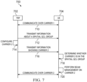
- FIG. 7 illustrates a sequence diagram of an embodiment method 700 for wireless communications.
- a TRP supports communications with UEs over multiple HF component carriers.
- a TRP 702 communicates with a UE 704 over a HF component carrier (i.e., carrier 1).
- carrier 1 may be understood as a primary carrier.
- the UE 704 may set up a wireless connection with the TRP 702 over the primary carrier using corresponding beam management procedures as described above.
- the TRP 702 transmits information about a spatial QCL group to the UE 704.
- the spatial QCL group includes a number of carriers that are spatially quasi co-located.
- the information about the spatial QCL group includes a group identifier identifying the spatial QCL group. According to the group identifier, the UE 704 may be able to determine the number of carriers in the spatial QCL group. In another example, the information about the spatial QCL group may also include carrier identifiers identifying the number of spatially quasi co-located carriers.
- the TRP 702 may broadcast the information in a physical broadcast channel, or may be transmitted in RRC, MAC-CE, DCI signaling or a combination thereof. Steps 710 and 712 may not be performed in an order as shown in FIG. 7 . For example, step 712 may be performed before step 710.
- the TRP 702 may determine to configure another HF component carrier (i.e., carrier 2) for communication with the UE 704, e.g., based on a service requirement or a transmission requirement.
- carrier 2 may be understood as a secondary carrier.
- the secondary carrier may be configured for uplink or downlink or both uplink and downlink transmissions.
- the TRP 702 may then transmit information to the UE 704, showing that the carrier 2 is configured for communications with the UE 704.
- the information may be control information.
- the TRP 702 may transmit the information to the UE 704 over carrier 2, or over carrier 1.
- FIG. 8 illustrates a sequence diagram of another embodiment method 800 for wireless communications.
- a TRP supports communications with UEs over multiple HF component carriers.
- a TRP 802 communicates with a UE 804 over a HF component carrier (i.e., carrier 1, primary carrier).
- the UE 804 may set up a wireless connection with the TRP 802 over the primary carrier using corresponding beam management procedures.
- the TRP 802 may determine to configure another HF component carrier (i.e., carrier 2, secondary carrier) for communications with the UE 804, e.g., based on a service requirement or a transmission requirement.
- the secondary carrier may be configured for uplink or downlink transmissions.
- the TRP 802 may communicate with the UE 804 showing whether carrier 2 is spatially quasi co-located with carrier 1.
- the TRP 802 may transmit a message to the UE 804.
- the message may include information or an indication indicating whether the secondary carrier is spatially quasi co-located with the primary carrier.
- the indication may be a bit value (e.g., a flag bit).
- a bit value of 1 may be used to indicate that the secondary carrier is spatially quasi co-located with the primary carrier, and a bit value of 0 may be used to indicate that the secondary carrier is not spatially quasi co-located with the primary carrier.
- the indication may be carried over RRC, MAC-CE or DCI signaling.
- the UE 804 performs beam management for communicating with the TRP 802 over the secondary carrier.
- the UE 804 may perform beam management for the secondary carrier based at least in part on beam management information of the primary carrier.
- FIG. 9 illustrates a flowchart of an embodiment 900 for wireless communications.
- the method may be performed by a TRP that communicates with UEs over multiple component carriers.
- the method 900 transmits a message including information identifying carriers that are in a spatial quasi co-location (SQCL) group, where the carriers in the SQCL group are spatially quasi co-located.
- the method 900 communicates with a first UE over a first carrier in the SQCL group. Step 904 may be performed before or at the same time as step 902.
- SQCL spatial quasi co-location
- the method 900 selects a second carrier in the SQCL group for communicating with the first UE, where the method 900 performs beam management for communications over the second carrier based at least in part on beam management information of the first carrier.
- the message may be transmitted in a broadcast channel, in radio resource control (RRC) signaling, in a media access control-control element (MAC-CE), in downlink control information (DCI) signaling or in a combination thereof.
- RRC radio resource control
- MAC-CE media access control-control element
- DCI downlink control information
- the method 900 may configure a first TRP beam for communications between the TRP and the first UE over the second carrier based at least in part on beam management information of the first carrier.
- the first TRP beam may include a transmit beam of the TRP or a receive beam of the TRP.
- FIG. 10 illustrates a flowchart of another embodiment 1000 for wireless communications.
- the method may be performed by a TRP that communicates with UEs over multiple component carriers.
- the method 1000 communicates with a UE over a first carrier.
- the method 1000 transmits a message that includes an indication indicating whether a second carrier configured for communications between the TRP and the UE is spatially quasi co-located with the first carrier, where the second carrier is different from the first carrier.
- the method 1000 may transmit the message in a broadcast channel, in radio resource control signaling, in a media access control-control element or downlink control information signaling.
- the method 1000 may further communicate with the UE over the second carrier.
- the second carrier is spatially quasi co-located with the first carrier, and the TRP performs beam management for communications on the second carrier based at least in part on beam management information of the first carrier.
- the method 1000 may configure a first TRP beam for communications between the TRP and the UE on the second carrier based at least in part on beam management information of the first carrier, and the first TRP beam includes a transmit beam of the TRP or a receive beam of the TRP.
- Configuring a TRP beam may include configuring a RS representing this TRP beam.
- spatial QCL may be configured between RSs in spatially quasi co-located carriers, such as between SS blocks, between CSI-RSs, between DMRSs, between a SS block and a CSI-RS, between a SS block and a DMRS, and/or between a CSI-RS and a DMRS.
- the method 1000 may configure a first CSI-RS (or a first SS block) in the second carrier based at least in part on a second CSI-RS (or a second SS block) in the first carrier.
- the first CSI-RS or the first SS block is spatially quasi co-located with the second CSI-RS or the second SS block.
- FIG. 11 illustrates a flowchart of yet another embodiment 1100 for wireless communications.
- the method may be performed by a UE that communicates with a TRP over multiple component carriers.
- the method 1100 receives, from a TRP, a message that includes information identifying carriers that are in a spatial quasi co-location (SQCL) group, where the carriers in the SQCL group are spatially quasi co-located.
- the method 1100 communicates with the TRP on a first carrier in the SQCL group, where the UE sets up a connection with the TRP according to a beam management procedure.
- Step 1104 may be performed before or at the same time as step 1102.
- the method 1200 may communicate with the TRP on the second carrier, where the second carrier is spatially quasi co-located with the first carrier, and the UE performs beam management for communications on the second carrier based at least in part on beam management information of the first carrier.
- the method 120 may configure a first beam for communications between the UE and the TRP on the second carrier based at least in part on beam management information of the first carrier, where the first beam includes a transmit beam of the UE or a receive beam of the UE.
- the method 1200 may further receive a first RS configuration in the second carrier, and detect a first RS in the second carrier based on the first RS configuration and based at least in part on a second RS in the first carrier, where the first RS is spatially quasi co-located with the second RS.
- Information about the spatial quasi co-location between the first RS and the second RS may be transmitted using RRC signaling, MAC-CE, DCI signaling, or a combination thereof.
- FIG. 13 illustrates a flowchart of yet another embodiment 1300 for wireless communications.
- the method 1300 may be performed by a TRP that communicates with UEs over multiple component carriers.
- the method 1300 transmits a message that includes an indication indicating that a second carrier is spatially quasi co-located with a first carrier.
- the method 1300 may configure a second reference signal representing a second TRP beam for communications between the TRP and a first UE in the second carrier.
- the method 1300 may configured the second reference signal based at least in part on a first reference signal representing a first TRP beam for communications between the TRP and the first UE in the first carrier.
- the second reference signal is spatially quasi co-located with the first reference signal.
- FIG. 14 illustrates a flowchart of yet another embodiment 1400 for wireless communications.
- the method 1400 may be performed by a UE that communicates with a TRP over multiple component carriers.
- the method 1400 receives a message that includes an indication indicating that a second carrier is spatially quasi co-located with a first carrier.
- the indication may indicate a spatial quasi co-location (SQCL) carrier group, where the SQCL carrier group includes the first carrier and the second carrier.
- the method 1400 may receive a second reference signal representing a second TRP beam for communications between the TRP and the UE in the second carrier.
- the second reference signal is spatially quasi co-located with a first reference signal representing a first TRP beam for communications between the TRP and the UE in the first carrier.
- the interfaces 1610, 1612, 1614 may be any component or collection of components that allow the processing system 1600 to communicate with other devices/components and/or a user.
- one or more of the interfaces 1610, 1612, 1614 may be adapted to communicate data, control, or management messages from the processor 1604 to applications installed on the host device and/or a remote device.
- one or more of the interfaces 1610, 1612, 1614 may be adapted to allow a user or user device (e.g., personal computer (PC), etc.) to interact/communicate with the processing system 1600.
- the processing system 1600 may include additional components not depicted in FIG. 16 , such as long term storage (e.g., non-volatile memory, etc.).
- the processing system 1600 is included in a network device that is accessing, or part otherwise of, a telecommunications network.
- the processing system 1600 is in a network-side device in a wireless or wireline telecommunications network, such as a base station, a relay station, a scheduler, a controller, a gateway, a router, an applications server, or any other device in the telecommunications network.
- the processing system 1600 is in a user-side device accessing a wireless or wireline telecommunications network, such as a mobile station, a user equipment (UE), a personal computer (PC), a tablet, a wearable communications device (e.g., a smartwatch, etc.), or any other device adapted to access a telecommunications network.
- a wireless or wireline telecommunications network such as a mobile station, a user equipment (UE), a personal computer (PC), a tablet, a wearable communications device (e.g., a smartwatch, etc.), or any other device adapted to access a telecommunications network.
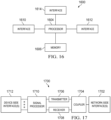
- FIG. 17 illustrates a block diagram of a transceiver 1700 adapted to transmit and receive signaling over a telecommunications network.
- the transceiver 1700 may be installed in a host device. As shown, the transceiver 1700 comprises a network-side interface 1702, a coupler 1704, a transmitter 1706, a receiver 1708, a signal processor 1710, and a device-side interface 1712.
- the network-side interface 1702 may include any component or collection of components adapted to transmit or receive signaling over a wireless or wireline telecommunications network.
- the transceiver 1700 may transmit and receive signaling over any type of communications medium.
- the transceiver 1700 transmits and receives signaling over a wireless medium.
- the transceiver 1700 may be a wireless transceiver adapted to communicate in accordance with a wireless telecommunications protocol, such as a cellular protocol (e.g., long-term evolution (LTE), etc.), a wireless local area network (WLAN) protocol (e.g., Wi-Fi, etc.), or any other type of wireless protocol (e.g., Bluetooth, near field communication (NFC), etc.).
- the network-side interface 1702 comprises one or more antenna/radiating elements.
- the network-side interface 1702 may include a single antenna, multiple separate antennas, or a multi-antenna array configured for multi-layer communication, e.g., single input multiple output (SIMO), multiple input single output (MISO), multiple input multiple output (MIMO), etc.
- the transceiver 1700 transmits and receives signaling over a wireline medium, e.g., twisted-pair cable, coaxial cable, optical fiber, etc.
- Specific processing systems and/or transceivers may utilize all of the components shown, or only a subset of the components, and levels of integration may vary from device to device.
- a signal may be transmitted by a transmitting unit or a transmitting module.
- a signal may be received by a receiving unit or a receiving module.
- a signal may be processed by a processing unit or a processing module.
- Other steps may be performed by a selecting unit/module, a configuring unit/module, a communicating unit/module, a determining unit/module, a broadcasting unit/module, an establishing unit/module, a specifying unit/module, and/or a detecting unit/module.
- the respective units/modules may be hardware, software, or a combination thereof.
- one or more of the units/modules may be an integrated circuit, such as field programmable gate arrays (FPGAs) or application-specific integrated circuits (ASICs).
- FPGAs field programmable gate arrays
- ASICs application-specific integrated circuits
- Step 1100 communicates with the TRP on a first carrier in the SQCL group, where the UE sets up a connection with the TRP according to a beam management procedure.
- Step 1104 may be performed before or at the same time as step 1102.
- the method 1100 determines whether a second carrier configured for communications between the TRP and the UE belongs to the SQCL group according to the received message, where the second carrier is different than the first carrier.
- the method 1100 communicates with the TRP on the second carrier in the SQCL group, where the UE performs beam management for communications on the second carrier based at least in part on beam management information of the first carrier.
- the method 1100 may also receive a first RS configuration in the second carrier.
- the method 1100 may detect the first RS in the second carrier based on the first RS configuration and at least in part on a second RS in the first carrier, where the first RS is spatially quasi co-located with the second RS.
- Information about the spatial quasi co-location of the first RS and the second RS may be transmitted using RRC signaling, MAC-CE, DCI signaling, or a combination thereof.
- FIG. 12 illustrates a flowchart of yet another embodiment 1200 for wireless communications.
- the method 1200 may be performed by a UE that communicates with a TRP over multiple component carriers.
- the method 1200 establishes a connection with a TRP for communications on a first carrier according to a beam management procedure.
- the method 1200 receives a message that includes an indication indicating whether a second carrier configured for communications between the TRP and the UE is spatially quasi co-located with the first carrier, where the second carrier is different than the first carrier.
- the method 1200 may communicate with the TRP on the second carrier, where the second carrier is spatially quasi co-located with the first carrier, and the UE performs beam management for communications on the second carrier based at least in part on beam management information of the first carrier.
- the method 120 may configure a first beam for communications between the UE and the TRP on the second carrier based at least in part on beam management information of the first carrier, where the first beam includes a transmit beam of the UE or a receive beam of the UE.
- the method 1200 may further receive a first RS configuration in the second carrier, and detect a first RS in the second carrier based on the first RS configuration and based at least in part on a second RS in the first carrier, where the first RS is spatially quasi co-located with the second RS.
- Information about the spatial quasi co-location between the first RS and the second RS may be transmitted using RRC signaling, MAC-CE, DCI signaling, or a combination thereof.
- FIG. 13 illustrates a flowchart of yet another embodiment 1300 for wireless communications.
- the method 1300 may be performed by a TRP that communicates with UEs over multiple component carriers.
- the method 1300 transmits a message that includes an indication indicating that a second carrier is spatially quasi co-located with a first carrier.
- the method 1300 may configure a second reference signal representing a second TRP beam for communications between the TRP and a first UE in the second carrier.
- the method 1300 may configured the second reference signal based at least in part on a first reference signal representing a first TRP beam for communications between the TRP and the first UE in the first carrier.
- the second reference signal is spatially quasi co-located with the first reference signal.
- FIG. 15 illustrates a flowchart of yet another embodiment 1500 for wireless communications.
- the method 1500 may be performed by a TRP that communicates with UEs over multiple component carriers.
- the method 1500 configures a first reference signal (RS) in a first carrier such that the first RS is spatially quasi co-located with a second RS in a second carrier.
- RS reference signal
- FIG. 16 illustrates a block diagram of an embodiment processing system 1600 for performing methods described herein, which may be installed in a host device.
- the processing system 1600 includes a processor 1604, a memory 1606, and interfaces 1610-1614, which may (or may not) be arranged as shown in FIG. 16 .
- the processor 1604 may be any component or collection of components adapted to perform computations and/or other processing related tasks
- the memory 1606 may be any component or collection of components adapted to store programming and/or instructions for execution by the processor 1604.
- the memory 1606 includes a non-transitory computer readable medium.
- the interfaces 1610, 1612, 1614 may be any component or collection of components that allow the processing system 1600 to communicate with other devices/components and/or a user.
- one or more of the interfaces 1610, 1612, 1614 may be adapted to communicate data, control, or management messages from the processor 1604 to applications installed on the host device and/or a remote device.
- one or more of the interfaces 1610, 1612, 1614 may be adapted to allow a user or user device (e.g., personal computer (PC), etc.) to interact/communicate with the processing system 1600.
- the processing system 1600 may include additional components not depicted in FIG. 16 , such as long term storage (e.g., non-volatile memory, etc.).
- the processing system 1600 is included in a network device that is accessing, or part otherwise of, a telecommunications network.
- the processing system 1600 is in a network-side device in a wireless or wireline telecommunications network, such as a base station, a relay station, a scheduler, a controller, a gateway, a router, an applications server, or any other device in the telecommunications network.
- the processing system 1600 is in a user-side device accessing a wireless or wireline telecommunications network, such as a mobile station, a user equipment (UE), a personal computer (PC), a tablet, a wearable communications device (e.g., a smartwatch, etc.), or any other device adapted to access a telecommunications network.
- a wireless or wireline telecommunications network such as a mobile station, a user equipment (UE), a personal computer (PC), a tablet, a wearable communications device (e.g., a smartwatch, etc.), or any other device adapted to access a telecommunications network.
- FIG. 17 illustrates a block diagram of a transceiver 1700 adapted to transmit and receive signaling over a telecommunications network.
- the transceiver 1700 may be installed in a host device. As shown, the transceiver 1700 comprises a network-side interface 1702, a coupler 1704, a transmitter 1706, a receiver 1708, a signal processor 1710, and a device-side interface 1712.
- the network-side interface 1702 may include any component or collection of components adapted to transmit or receive signaling over a wireless or wireline telecommunications network.
- the coupler 1704 may include any component or collection of components adapted to facilitate bi-directional communication over the network-side interface 1702.
- the transmitter 1706 may include any component or collection of components (e.g., up-converter, power amplifier, etc.) adapted to convert a baseband signal into a modulated carrier signal suitable for transmission over the network-side interface 1702.
- the receiver 1708 may include any component or collection of components (e.g., down-converter, low noise amplifier, etc.) adapted to convert a carrier signal received over the network-side interface 1702 into a baseband signal.
- the signal processor 1710 may include any component or collection of components adapted to convert a baseband signal into a data signal suitable for communication over the device-side interface(s) 1712, or vice-versa.
- the device-side interface(s) 1712 may include any component or collection of components adapted to communicate data-signals between the signal processor 1710 and components within the host device (e.g., the processing system 1600, local area network (LAN) ports,
- the transceiver 1700 may transmit and receive signaling over any type of communications medium.
- the transceiver 1700 transmits and receives signaling over a wireless medium.
- the transceiver 1700 may be a wireless transceiver adapted to communicate in accordance with a wireless telecommunications protocol, such as a cellular protocol (e.g., long-term evolution (LTE), etc.), a wireless local area network (WLAN) protocol (e.g., Wi-Fi, etc.), or any other type of wireless protocol (e.g., Bluetooth, near field communication (NFC), etc.).
- the network-side interface 1702 comprises one or more antenna/radiating elements.
- the network-side interface 1702 may include a single antenna, multiple separate antennas, or a multi-antenna array configured for multi-layer communication, e.g., single input multiple output (SIMO), multiple input single output (MISO), multiple input multiple output (MIMO), etc.
- the transceiver 1700 transmits and receives signaling over a wireline medium, e.g., twisted-pair cable, coaxial cable, optical fiber, etc.
- Specific processing systems and/or transceivers may utilize all of the components shown, or only a subset of the components, and levels of integration may vary from device to device.
Landscapes
- Engineering & Computer Science (AREA)
- Signal Processing (AREA)
- Computer Networks & Wireless Communication (AREA)
- Mobile Radio Communication Systems (AREA)
Description
- The present invention relates generally to wireless communications, and in particular embodiments, to techniques and mechanisms for beam management in high frequency multi-carrier operations with spatial quasi co-location.
- In 5G new radio (NR), high frequency carriers, such as mmWave carriers, are used to provide high data rate wireless communications. However, high frequency carriers suffer from significant path loss, causing reduced transmission efficiency. Beamforming techniques have been employed to combat the path loss of high frequency waveforms, where a number of high-gain transmit and/or receive beams are formed in different angular directions, and possibly at different time slots, for transmitting and receiving wireless signals. Beam management procedures are also defined and used to manage beamforming processes.
-
US 2014/0198763 A1 refers to methods and apparatuses for improved reference signal reception in a wireless device configured for operation in a wireless communication network. In one example, the network provides assistance information that indicates a received timing or frequency offset of a second reference signal relative to a first reference signal that is transmitted from a first antenna port. The second reference signal is transmitted by the wireless communication network from a second antenna port that is quasi co-located with the first antenna port with respect to timing, frequency and/or delay spread, and the wireless device is configured to use the assistance information to configure its receiver timing and/or frequency offset for reception of the second reference signal. Such operation reduces the "search" space in time and/or frequency needed at the wireless device. -
US 2015/0341882 A1 refers to devices, systems and methods for Cross-Carrier Quasi Co-Location Signaling in an NCT Wireless Network. A UE device may include a receiver circuit to receive a QCL signaling message from a primary cell, the QCL signaling message for a configured secondary cell to identify a primary or one or more secondary cells that are Quasi Co-located with the secondary cell for which the message is provided. The UE device may also include a QCL signal decoding module to decode the QCL signaling message and to determine QCL synchronization parameters. The UE device may further include a synchronization module to synchronize the UE with the primary or one or more secondary cells based on the QCL synchronization parameters obtained from the QCL message received from the primary cell. -
US 2015/0372851 A1 refers to a radio base station having a configuring section that configures a first carrier type subframe in which cell-specific reference signals are mapped at a predetermined density, and a second carrier type subframe in which cell-specific reference signals are mapped at a density that is lower than the density of the first carrier type subframe; a generating section that, when configuring the second carrier type subframe, generates at least a synchronization signal to use for frequency synchronization; and a transmitting section that transmits association information for associating the synchronization signal with an other downlink signal that is transmitted in the second carrier type subframe. - Further, prior art document R2-166125, 3GPP TSG RAN WG2 Meeting #95bis, 10th - 14th October 2015 refers to an NR cell for idle state.
- Further, prior art document R1-1609414, 3GPP TSG RAN WG1 Meeting #86bis refers to a discussion on beam management aspects for DL-MIMO.
- Technical advantages are generally achieved, by embodiments of this disclosure which describe a system and method for beam management in high frequency multi-carrier operations with spatial quasi co-location. This problem is solved by the subject matter of the independent claims. Embodiments labelled as inventive embodiments in the following, which are not covered by the scope of protection defined by the independent claims, are to be understood as examples helpful for understanding the invention, but not as embodiments of the invention.
- According to one aspect of the present disclosure, there is provided a method that includes:
- communicating with a user equipment, UE, over a first carrier, wherein for the communication with the UE over the first carrier the TRP uses a first reference signal representing a first TRP transmit beam;
- transmitting a first message comprising information about one of a plurality of spatial Quasi-Co-Location, SQCL, group to the UE,
- ∘ each of the plurality of the SQCL groups including an SQCL group identifier, identifying the respective SQCL group,
- ∘ each of the SQCL groups comprising multiple different carriers being spatially co-located with respect to each other, wherein the information about the one of the SQCL groups contains carrier identifiers of the multiple different carriers, and the first carrier and a second carrier are part of the one of the SQCL groups;
- a.) determining to configure the second carrier for the communication with the UE based on a service requirement or a transmission;
- b.) transmitting a second message comprising information to the UE, the information indicating that the second carrier is configured for the communciation with the UE;
- c.) configuring a second reference signal representing a second TRP transmit beam for communications between the TRP and the UE in the second carrier based at least in part on the first reference signal representing the first TRP transmit beam, the second reference signal being spatially quasi co-located with the first reference signal.
- Optionally, in any of the preceding aspects, the message is transmitted in a broadcast channel, radio resource control (RRC) signaling, a media access control-control element (MAC-CE), downlink control information (DCI) signaling, or a combination thereof.
- According to yet another aspect of the present disclosure, there is provided a method that includes:
- communicating with a transmit receive point, TRP, on a first carrier in one of a plurality of spatial Quasi-Co-Location, SQCL, groups,
- ∘ wherein for the communication with the TRP the UE receives a first reference signal by using a first receive beam, the first reference signal representing a first TRP transmit beam,
- ∘ wherein each of the plurality of the SQCL groups including an SQCL group identifier, identifying the respective SQCL group,
- ∘ wherein each of the SQCL groups includes multiple different carriers, the multiple different carriers being spatially quasi-colocated with respect to each other;
- receiving a first message comprising information about the one of the SQCL groups from the TRP, wherein the information about the SQCL group contains carrier identifiers of the multiple carriers, and the first carrier and a second carrier are part of the SQCL group;
- a.) receiving a second message from the TRP, the second message including information indicating that the second carrier is configured for the communciation with the UE;
- b.) determining that the second carrier belongs to the SQCL group according to the carrier identifiers and according to the information indicating that the second carrier is configured for the communication with the UE;
- c.) configuring a second receive beam for a communication with the TRP on the second carrier based at least in part on beam management information of the first carrier.
- Optionally, in any of the preceding aspects, receiving the message comprises receiving the message in a broadcast channel, in radio resource control (RRC) signaling, a media access control-control element (MAC-CE), downlink control information (DCI) signaling, or a combination thereof.
- For a more complete understanding of the present disclosure, and the advantages thereof, reference is now made to the following descriptions taken in conjunction with the accompanying drawings, in which:
-
FIG. 1 illustrates a diagram of an embodiment wireless communications network; -
FIG. 2 illustrates a diagram of another embodiment wireless communications network; -
FIG. 3 illustrates a diagram of yet another embodiment wireless communications network; -
FIG. 4 illustrates a graph showing received powers on two high frequency component carriers varying with angles of arrival; -
FIG. 5 illustrates another graph showing received powers on two high frequency component carriers varying with angles of arrival; -
FIG. 6 illustrates a graph showing cumulative distribution functions of differences between received powers of two high frequency component carriers; -
FIG. 7 illustrates a sequence diagram of an embodiment method for wireless communications; -
FIG. 8 illustrates another sequence diagram of an embodiment method for wireless communications; -
FIG. 9 illustrates a flowchart of an embodiment method for wireless communications; -
FIG. 10 illustrates a flowchart of another embodiment method for wireless communications; -
FIG. 11 illustrates a flowchart of yet another embodiment method for wireless communications; -
FIG. 12 illustrates a flowchart of yet another embodiment method for wireless communications; -
FIG. 13 illustrates a flowchart of yet another embodiment method for wireless communications; -
FIG. 14 illustrates a flowchart of yet another embodiment method for wireless communications; -
FIG. 15 illustrates a flowchart of yet another embodiment method for wireless communications; -
FIG. 16 illustrates a diagram of an embodiment processing system; and -
FIG. 17 illustrates a diagram of an embodiment transceiver. - Corresponding numerals and symbols in the different figures generally refer to corresponding parts unless otherwise indicated. The figures are drawn to clearly illustrate the relevant aspects of the embodiments and are not necessarily drawn to scale.
- The making and using of embodiments of this disclosure are discussed in detail below. It should be appreciated, however, that the concepts disclosed herein can be embodied in a wide variety of specific contexts, and that the specific embodiments discussed herein are merely illustrative and do not serve to limit the scope of the claims.
- Beam management is performed when beamforming techniques are utilized for communications over high frequency carriers to compensate for path loss due to the use of high frequency carriers. When multiple component carriers are spatially quasi co-located, beam management of a first component carrier may be performed based at least in part on related information of a second component carrier. This reduces beam management overhead of the first component carrier, and improves communications performance. The related information may include beam management information of the second component carrier that is obtained or produced during beam management in the second component carrier.
- In some embodiments, with the knowledge of spatially quasi co-located component carriers, a transmit-receive point (TRP) or a user equipment (UE) that supports communication over multiple component carriers, may perform beam management for one component carrier based at least in part on beam management information of the other component carrier. For example, the TRP or the UE may configure a transmit or receive beam in a first component carrier based at least in part on beam management information of a second component carrier that is spatially quasi co-located with the first component carrier. In some embodiments, configuring a TRP beam may include configuring a reference signal (RS) representing the TRP beam. For example, when two carriers (e.g.,
Carrier 1 and Carrier 2) are spatially quasi co-located with each other, a TRP may configure a first TRP beam inCarrier 1 for communications with a UE based on a second TRP beam inCarrier 2 that is used for communications with the UE. In this case, the TRP may configure a first RS representing the first TRP beam inCarrier 1 based at least in part on a second RS representing the second TRP beam incarrier 2. The first RS is spatially quasi co-located with the second RS. - In some embodiments, information about spatially quasi co-located component carriers may be transmitted to a UE. Based on the transmitted information, the UE may determine the spatial quasi colocation among the component carriers. In some embodiments, the information about spatially quasi colocated component carriers may include the component carriers that are spatially quasi co-located. For example, a message may be sent to the UE including identifiers of the spatially quasi co-located component carriers, where each of the identifiers identifies one of the spatially quasi co-located component carriers. Component carriers that are spatially quasi co-located are grouped into a spatial quasi co-location (SQCL) group. Multiple SQCL groups are formed, each including a set of spatially quasi colocated carriers, and being assigned an SQCL group identifier identifying the respective SQCL group. In this case, the information about spatially quasi co-located component carriers includes one or more SQCL group identifiers, and carrier identifiers identifying component carriers under the respective SQCL groups. In some embodiments, the information about spatially quasi co-located component carriers may include an indication indicating that the component carriers are spatially quasi co-located. The indication may include any control information or signal that directly or indirectly references the spatially quasi co-located component carriers. For example, a message may be sent to the UE including a bit value that indicates whether a first carrier is spatially quasi co-located with a second carrier. In one example, a bit value of 1 may indicate that the first carrier is spatially quasi co-located with the second carrier, while a bit value of 0 may indicate that the first carrier is not spatially quasi co-located with the second carrier. A field, e.g., a control information field, may be defined to carry the bit value and indicates spatial quasi co-location between two carriers. For example, a control field may be defined in a radio resource control (RRC) message, a MAC control element (MAC-CE), or downlink control information (DCI) to indicate SQCL of components. In another example, the bit value may be a flag bit. In another example, the indication may be carried in a field associated with a SQCL group, or include an identifier of the SQCL group that include the first and the second carriers.
- In one example, a UE may communicate with a TRP over a first carrier. When the TRP configures to communicate with the UE over a second carrier, the UE may determine whether the second carrier is spatially quasi co-located with the first carrier according to the above described information transmitted by the TRP. When the second carrier is spatially quasi co-located with the first carrier, the UE may perform beam management for communicating over the second carrier based on beam management information or related information of the first carrier. In one example, the UE may check whether the first carrier and second carrier belong to a SQCL group to determine whether the two carriers are spatially quasi co-located. In another embodiment, the UE may check whether there is any information (e.g., a flag bit) indicating that the second carrier is spatially quasi co-located with the first carrier. In some embodiments, information about spatially quasi co-located reference signals may also be transmitted to UEs. The information about spatially quasi co-located reference signals may include an indication that indicates whether a first reference signal in the first carrier is spatially quasi co-located with a second reference signal in the second carrier. Similarly, an indication of spatially quasi co-located reference signals may include any control information or signal that directly or indirectly references the spatially quasi co-located reference signals, such as a field associated with spatially quasi co-located reference signals, a value indicating that reference signals are spatially quasi co-located with one another. The information about spatially quasi co-located component carriers or spatially quasi co-located reference signals may be transmitted in broadcast signaling, radio resource control (RRC) signaling, a media access control-control element (MAC-CE), downlink control information (DCI) signaling, or a combination thereof.
-
FIG. 1 illustrates anetwork 100 for communicating data. Thenetwork 100 comprises abase station 110 having acoverage area 101, a plurality ofmobile devices 120, and abackhaul network 130. As shown, thebase station 110 establishes uplink (dashed line) and/or downlink (dotted line) connections with themobile devices 120, which serve to carry data from themobile devices 120 to thebase station 110 and vice-versa. Data carried over the uplink/downlink connections may include data communicated between themobile devices 120, as well as data communicated to/from a remote-end (not shown) by way of thebackhaul network 130. As used herein, the term "base station" refers to any component (or collection of components) configured to provide wireless access to a network, such as a transmit-receive point (TRP), an enhanced base station (eNB), a macro-cell, a femtocell, a Wi-Fi access point (AP), or other wirelessly enabled devices. Base stations may provide wireless access in accordance with one or more wireless communication protocols, e.g., long term evolution (LTE), LTE advanced (LTE-A), High Speed Packet Access (HSPA), Wi-Fi 802.11a/b/g/n/ac, 5G new radio (NR), etc. As used herein, the term "mobile device" refers to any component (or collection of components) capable of establishing a wireless connection with a base station, such as a user equipment (UE), a mobile station (STA), and other wirelessly enabled devices. In some embodiments, thenetwork 100 may comprise various other wireless devices, such as relays, low power nodes, etc. - The
network 100 may provide wireless communications over a single carrier, or over an aggregation of different component carriers (i.e., carrier aggregation). The different component carriers may be in different bands or in the same bands. For example, thenetwork 100 may support carrier aggregation of multiple low frequency (LF) component carriers, multiple high frequency (HF) component carriers, or a LF component carrier and a HF component carrier. - The different component carriers may be co-located (or co-sited) or located in different sites.
FIG. 2 illustrates a diagram of anembodiment network 200 for wireless communications, where different component carriers are co-located. As shown, thenetwork 200 includes aTRP 202 and aTRP 204 co-located in the same site. TheTRP 202 andTRP 204 communicate with a plurality ofUEs 206 in a coverage area of 208 over a LF carrier and a high frequency carrier, respectively. As such, the LF carrier and the high frequency carrier are co-located.FIG. 3 illustrates a diagram of anotherembodiment network 300 for wireless communications, where different component carriers are located in different sites. Thenetwork 300 supports wireless communications with a plurality of UEs over two different high frequency carriers provided by aTRP 302 and aTRP 304, and over a LF carrier provided by aTRP 306. As shown,TRPs TRP 302 providing acoverage area 308,TRP 304 providing acoverage area 310, and the three TRPs providing acoverage area 312.TRP 302 is connected toTRP 306 via abackhaul network 314, andTRP 304 is connected toTRP 306 via abackhaul network 316. - In general, a LF carrier can provide large coverage and robust connections but a relatively low data rate, and a high frequency carrier can provide a high data rate because of its large bandwidth. However, a HF carrier generally has small coverage due to large path loss, and link robustness is also a concern in HF transmissions. In 5G new radio (NR), due to the introduction of high frequencies, channel characteristics of component carriers in multiple carrier operations may be substantially different. In particular, millimetre wave high frequency (HF) links suffer inherently from large path loss and random blockage. To compensate the path loss, beamforming techniques are used, where a number of high-gain transmit and/or receive beams are formed for transmitting and receiving wireless signals. Each of the beams may cover only a small region in an angular direction. The beams may be referred to as directional beams. As a result, transmissions performed through the formed beams become highly directional. Beamforming may be used to mimic omni-directional transmissions or transmissions covering a large area within a range of angles by forming multiple beams at different directions, possibly over different time slots. In high frequency communications, a large number of antenna elements is required to bring a sufficient transmit/receive gain. In this case, significantly large overhead may be caused, e.g., in beam identification for initial access, or in beam management for communications in connected states.
- Beam management may be performed to manage beamforming procedures on a UE side or a TRP side. According to the 3rd Generation Partnership Project (3GPP) technical report (TR) 38.802 V2.0.0 (2017-03), beam management in NR is defined as (see section 6.1.6.1):
- a set of L1/L2 procedures to acquire and maintain a set of TRP(s) and/or UE beams that can be used for downlink (DL) and uplink (UL) transmission/reception, which include at least following aspects:
- Beam determination: for TRP(s) or UE to select of its own Tx/Rx beam(s).
- Beam measurement: for TRP(s) or UE to measure characteristics of received beam-formed signals
- Beam reporting: for UE to report information of beam-formed signal(s) based on beam measurement
- Beam sweeping: operation of covering a spatial area, with beams transmitted and/or received during a time interval in a predetermined way.
- According to 3GPP TR 38.802 V2.0.0 (see section 6.1.6.1), the following DL L1/L2 beam management procedures are supported within one or multiple TRPs:
- P-1: is used to enable UE measurement on different TRP Tx beams to support selection of TRP Tx beams/UE Rx beam(s)
For beamforming at TRP, it typically includes an intra/inter-TRP Tx beam sweep from a set of different beams. For beamforming at UE, it typically includes a UE Rx beam sweep from a set of different beams. - P-2: is used to enable UE measurement on different TRP Tx beams to possibly change inter/intra-TRP Tx beam(s)
From a possibly smaller set of beams for beam refinement than in P-1. Note that P-2 can be a special case of P-1. - P-3: is used to enable UE measurement on the same TRP Tx beam to change UE Rx beam in the case UE uses beamforming
- Uplink beam management may include uplink L1/L2 beam management procedures similar to the DL L1/L2 beam management procedures described above, with procedures U-1, U-2 and U-3 corresponding to the procedures P-1, P-2 and P-3, respectively. Beamforming based access and beam management may incur large overhead in HF communications. For example, performing beam sweeping from a large amount of transmission beams by a TRP for downlink transmissions may take long time and consume significant TRP power. In another example, when a TRP supports multiple component carriers, beam management may need to be performed separately and independently for each of the component carriers.
- Quasi-colocation, (or quasi co-location, QCL) is also defined in 3GPP TR 38.802 V2.0.0, section 6.1.6.5, where definition of QCL is that "two antenna ports are said to be quasi co-located if properties of the channel over which a symbol on one antenna port is conveyed can be inferred from the channel over which a symbol on the other antenna port is conveyed." QCL as defined supports the following functionalities at least
- Beam management functionality: at least including spatial parameters
- Frequency/timing offset estimation functionality: at least including Doppler/delay parameters
- RRM management functionality: at least including average gain
- It has been shown that in a case of aggregation of multiple HF carriers, and when two TRPs, each of which provides communications services over a HF carrier, are co-located, and the two high frequencies are sufficiently close to each other, the two HF carriers show similar receive power distribution in the spatial domain. In one example, measurements of received powers by UEs on two HF component carriers in the spatial angle of arrival (AoA) domain may be obtained to show the similarity. In this example, the two HF component carriers are co-located at a TRP as an indoor hotspot and in a frequency band of 28GHz.
Carrier 1 has a bandwidth of 200 MHz at 27.9 GHz, andcarrier 2 has a bandwidth of 200 MHz at 28.1 GHz.FIG. 4 is agraph 400 showing how received powers on the two HF component carriers vary with AoA in a scenario having line-of-sight (LOS). The x-axis represents AoA in degrees, and the y-axis represents received powers in dB.FIG. 5 is agraph 500 showing how received powers on the two HF component carriers vary with AoA in a scenario of non-line-of-sight (NLOS). As shown inFIG. 4 and FIG. 5 , power distributions of the two HF component carriers in the AoA domain are very similar to each other. In general, more than 95% power differences betweencarrier 1 andcarrier 2 in the case of LOS are less than 4dB, and more than 90% power differences betweencarrier 1 andcarrier 2 in the case of NLOS are less than 4dB.FIG. 6 is agraph 600 showing cumulative distribution functions (CDFs) of differences between received powers of the two HF component carriers in the scenarios of LOS and NLOS, respectively. As seen, the CDFs in the cases of LOS and NLOS are also very close to each other, and the LOS or NLOS does not affect power distribution properties of the two HF component carriers. - The example as illustrated in
FIGs. 4-6 shows that spatial QCL (in terms of downlink beam profiles) may be established across the two HF component carriers in the case of the multiple-HF carriers operations. In this case, beam management information (e.g., received power) about one HF component carrier may be, at least partly, reused in beam management of the other, reducing beam management overhead. - Embodiments of the present disclosure recognize that when two or more HF component carriers are generally spatially quasi co-located (or spatially quasi-colocated), or when spatial QCL can be established across the two or more HF component carriers, the two or more HF component carriers have similar beam profiles. In this case, beam management information of one HF component carrier may be used, at least in part, by another HF component carrier in performing beam management procedures, or may be at least useful or helpful in performing beam management procedure by one another. In general, two HF component carriers are spatially quasi co-located when 1) the component carriers are co-located (or co-sited), and 2) the component carriers are close to each other in frequency. In some embodiments, reference signals, e.g., synchronization signals (SSs), CSI-RSs or demodulation reference signals (DMRSs), etc., in one HF component carrier may be configured to be spatially quasi co-located with reference signals (e.g., SSs, CSI-RSs or DMRSs, etc.) in another spatially quasi co-located HF component carrier. In some embodiments, when a HF component carrier is co-located with a LF component carrier, a spatial QCL may also be established across the HF component carrier and the LF component carrier. In this case, related information of the LF component carrier, such as a direction of arrival (DoA), may also be helpful or used in performing beam management of the HF component carrier. In some embodiments, reference signals (e.g., SSs, CSI-RSs or DMRSs, etc.) in the HF component carrier may be configured to be spatially quasi co-located with reference signals (e.g., SSs, CSI-RSs or DMRSs, etc.) in the LF component carrier.
- When two carriers (e.g.,
carrier 1 and carrier 2) are spatially quasi co-located, a reference signal (RS), such as a SS, a CSI-RS, a DMRS, etc., in one carrier may be configured to be spatially quasi co-located with another RS in the other carrier. For example, a CSI-RS incarrier 1 may be configured to be spatially quasi co-located with a CSI-RS incarrier 2. In another example, a CSI-RS incarrier 1 may be configured to be spatially quasi co-located with a SS incarrier 2. In yet another example, a SS incarrier 1 may be configured to be spatially quasi co-located with a CSI-RS incarrier 2. In yet another example, a SS inCarrier 1 may be configured to be spatially quasi co-located with a SS incarrier 2. A RS in this disclosure may refer to a SS (or a SS block), a CSI-RS, a DMRS, a phase tracking reference signal (PTRS), a tracking reference signal (TRS), or a sounding reference signal (SRS), or any other reference signals used in wireless communications. - Establishing spatial QCL across multiple component carriers is beneficial for reducing beam management overhead, simplifying beam management procedures, improving communication efficiency, and improving quality of service and user experience. The benefits may include shortened beam sweep time, reduced beam management power consumption, faster beam determination, shortened transmission latencies, and reduced overhead associated with beam management reference signals, among others.
- A beam profile may include beam management information that is produced or obtained during beam management procedures, or information that is related to beam management. Examples of beam management information may include measurements reported by UEs, such as reference signal received power (RSRP), and reference signal received quality (RSRQ), a downlink and/or uplink beam group, downlink and/or uplink beam, downlink and/or uplink beam angles, such as AoAs, beam pair links (BPLs), such as a pair of transmit beam and receive beam, a reference signal, beam powers, and beam gains. For example, RSRP or RSRQ of a TRP transmit beam may be obtained during a beam measurement and reporting procedure of a UE. In another example, a BPL may be produced during a beam determination procedure where a TRP determines or selects a receive beam corresponding to a transmit beam of a UE, or where a UE determines or selects a receive beam corresponding to a transmit beam of a TRP. Information that is related to beam management may generally include a direction of a received or a transmitted signal. The direction may be used when determining beam sweeping region or a transmit/receive beam during beam management.
- With spatial QCL is established across multiple component carriers, and/or spatial QCL is configured between reference signals of the multiple component carriers, beam management information of one component carrier may be reused or used during beam management procedures of another. In one embodiment, when two HF component carrier (e.g.,
carrier 1 and carrier 2) are spatially quasi co-located, for downlink beam management, a TRP may perform downlink beam sweeping (e.g., procedure P-1) forcarrier 1 in a region that is determined based on RSRPs (or RSRQs) reported forcarrier 2. The RSRP (and/or RSRQ) may be based on UE measurements on corresponding downlink reference signals (such as SSs, CSI-RSs or DMRSs, etc.). For example, the TRP may identify a TRP transmit beam incarrier 2 based on the RSRP (and/or RSRQ) reported by UEs, and determine the region based on the TRP transmit beam incarrier 2. In another embodiment, a TRP or a UE may skip procedure P-1 and starts procedure P-2 and/or P-3 based on a BPL that has been determined forcarrier 2 to select a refined TRP transmit beam forcarrier 1, and/or to select a refined UE receive beam forcarrier 1. In yet another embodiment, a TRP or a UE may configure a transmit beam or a receive beam incarrier 1 based on beam management information ofcarrier 2. - In some embodiments, a first RS (e.g., a CSI-RS, a DMRS, or a SS block) in
carrier 1 may be spatially quasi co-located with a second RS (e.g., a CSI-RS, a DMRS, or a SS block) incarrier 2. In this case, a TRP may configure the first RS forcarrier 1 based at least in part on the RS that has been used forcarrier 2. In one example of CSI-RS, CSI-RSs forcarrier 1 andcarrier 2 may have different periodicities or densities. For example, a CSI-RS forcarrier 1 may have a longer periodicity than a CSI-RS forcarrier 2. In another example, a CSI-RS forcarrier 1 may have a lower density in frequency thancarrier 2. Configuration of the first RS forcarrier 1 may include information about resource elements for carrying RSs, e.g., a number of the resource elements, and/or location of the resource elements in a resource block. Information specifying spatial QCL between the first RS and the second RS may also be transmitted to one or more UEs, e.g., via RRC, MAC-CE, DCI signaling or a combination thereof, and in a carrier, e.g., incarrier 1 orcarrier 2. When the TRP transmits the first RS in a first RS resource incarrier 1 to a UE, the UE may detect the first RS incarrier 1 based on the RS configuration incarrier 1 and at least in part on the second RS incarrier 2, where the first RS incarrier 1 is spatially quasi co-located with the second RS incarrier 2. In one example, the UE may determine that the same receive beam used to receive the second RS incarrier 2 may be used to receive the first downlink RS incarrier 1, where the first RS incarrier 1 is spatially quasi co-located with the second RS incarrier 2. In another example, the UE may select a beam to receive the first downlink RS incarrier 1, where the beam has the same spatial characteristics (e.g., beam direction, beamforming gain, beam width, etc.) as a beam used to receive the second RS incarrier 2, and where the first RS incarrier 1 is spatially quasi co-located with the second RS incarrier 2. In these cases, the UE doesn't need to detect and determine a receive beam incarrier 1 from scratch (e.g., procedure p-1) and significant beam detection overhead is thus avoided. - In some embodiments, configuring a TRP beam may include configuring a RS representing the TRP beam. When two carriers (e.g.,
Carrier 1 and Carrier 2) are spatially quasi co-located with each other, a TRP may configure a first TRP beam inCarrier 1 for communications with a UE based on a second TRP beam inCarrier 2 that is used for communications with the UE. In one embodiment, the TRP may configure a first RS representing the first TRP beam inCarrier 1 based at least in part on a second RS representing the second TRP beam incarrier 2. The first RS is spatially quasi co-located with the second RS. The first TRP beam may be a receive TRP beam or a transmit TRP beam. In one example, the TRP may send the first RS in the first TRP beam ofCarrier 1 to the UE, and may configure a receive TRP beam based on the first TRP beam for receiving uplink signals from the UE inCarrier 1. The UE may configure a first UE beam to receive the first RS that is sent in the first TRP beam ofCarrier 1. In one example, the UE may configure the first UE beam inCarrier 1 for receiving the first RS based on a second UE beam that has been configured for receiving the second RS sent from the TRP in the second TRP beam ofCarrier 2, where the first RS is spatially quasi co-located with the second RS. Information specifying that the first RS is spatially quasi co-located with the second RS may be transmitted to the UE by RRC signaling, a MAC-CE, DCI signaling, or a combination thereof. - In some embodiments, when two HF component carriers (e.g.,
carrier 1 and carrier 2) are spatially quasi co-located, beam management information in one carrier may be directly used in beam management of the other carrier. For example, when a TRP (or a UE) performs transmissions on a transmit beam incarrier 1 with the UE (or the TRP), the TRP (or UE) may directly use the transmit beam for transmissions with the UE (or the TRP) incarrier 2 without going through procedures of beam sweeping and beam determination. Two spatially quasi co-located HF component carriers may be referred to as mutually and spatially calibrated when there is a beam mapping between the two HF component carriers in terms of beam direction from a TRP perspective or from a UE perspective. For example, when spatially quasi co-locatedHF carrier 1 andcarrier 2 are mutually and spatially calibrated, there is a beam mapping between a first beam incarrier 1 and a second beam incarrier 2. In this case, the first and the second beams have the same or similar spatial characteristics (e.g., same beam direction, power distribution, etc.), and when the first beam in carrier 1 (or the second beam in carrier 2) is known (e.g., determined or identified), the corresponding mapping beam, i.e., the second beam in carrier 2 (or the first beam in carrier 1) will also be known. In one example, when a TRP or a UE identifies a downlink or uplink beam pair link incarrier 1 with beam management, the TRP and the UE may directly form a downlink or uplink beam pair link incarrier 2. If the two HF component carriers are co-sited but not mutually and spatially calibrated, beam management information in one component carrier may still be helpful for beam management in the other component carrier. For example, when a UE already found a generally best receive beam and transmit beam pair for communications with a TRP overcarrier 1, beam management for communications with the TRP overcarrier 2 may be done by only performing procedure P-2 in downlink and procedure U-2 in uplink based on the beam pair. - In some embodiments, when a HF component carrier (HF carrier) and a LF component carrier (LF carrier) are spatially quasi co-located, DoA information obtained in the LF carrier with respect to a UE may be used for beam management in the HF carrier for the same UE. For example, when a TRP has obtained downlink DoA information in the LF carrier, downlink beam management of the TRP in the HF carrier may be started with procedure P-3 based on the DoA information, skipping procedures P-1 and P-2. In this case, the TRP determines a downlink beam based on the DoA information and the UE sweeps receive beams to identify the best receive beam with the procedure P-3. The HF carrier and the LF carrier may be referred to as mutually and spatially calibrated when there is a mapping between a beam direction in the HF carrier and a DoA in the LF carrier from a TRP perspective. In this case, a beam in the HF carrier may be determined directly based on the DoA in the LF carrier. In one example, the spatial QCL between a CSI-RS in HF carrier and a beamformed CSI-RS in LF carrier may be established and made known to a UE.
- Component carriers that are spatially quasi co-located may be pre-determined or pre-specified, or determined dynamically. Information about the spatially quasi co-located component carriers, or information about whether a component carrier is spatially quasi co-located with another component carrier, may be transmitted to both a transmitter and a receiver in communications, so that both the transmitter and the receiver may make use of the information for beam management. For example, when a TRP or a UE performs beam management for a HF component carrier, e.g., determining a downlink beam or an uplink beam, the TRP or the UE may determine whether the HF component carrier is spatially quasi co-located with one or more other component carriers based on the transmitted information, and then perform beam management using beam management information or other related information of the other spatially quasi co-located component carriers.
- Information about spatially quasi co-located component carriers and/or RSs is transmitted to a UE, e.g., by a TRP, in broadcast signaling, radio resource control signaling, downlink control information signaling, a media access control-control element (MAC-CE) or a combination thereof. A spatial QCL group is formed or specified for each set of spatially quasi co-located component carriers. These spatially quasi co-located component carriers have the same or similar beam profiles. Information about the spatial QCL group is transmitted to UEs, e.g., using the signaling as described above.
-
FIG. 7 illustrates a sequence diagram of anembodiment method 700 for wireless communications. In this example, a TRP supports communications with UEs over multiple HF component carriers. As shown, atstep 710, aTRP 702 communicates with aUE 704 over a HF component carrier (i.e., carrier 1). In this example,carrier 1 may be understood as a primary carrier. TheUE 704 may set up a wireless connection with theTRP 702 over the primary carrier using corresponding beam management procedures as described above. Atstep 712, theTRP 702 transmits information about a spatial QCL group to theUE 704. The spatial QCL group includes a number of carriers that are spatially quasi co-located. The information about the spatial QCL group includes a group identifier identifying the spatial QCL group. According to the group identifier, theUE 704 may be able to determine the number of carriers in the spatial QCL group. In another example, the information about the spatial QCL group may also include carrier identifiers identifying the number of spatially quasi co-located carriers. TheTRP 702 may broadcast the information in a physical broadcast channel, or may be transmitted in RRC, MAC-CE, DCI signaling or a combination thereof.Steps FIG. 7 . For example, step 712 may be performed beforestep 710. Atstep 714, theTRP 702 may determine to configure another HF component carrier (i.e., carrier 2) for communication with theUE 704, e.g., based on a service requirement or a transmission requirement. In this example,carrier 2 may be understood as a secondary carrier. The secondary carrier may be configured for uplink or downlink or both uplink and downlink transmissions. Atstep 716, theTRP 702 may then transmit information to theUE 704, showing that thecarrier 2 is configured for communications with theUE 704. The information may be control information. TheTRP 702 may transmit the information to theUE 704 overcarrier 2, or overcarrier 1. Atstep 718, theUE 704 may determine whether the secondary carrier (i.e., carrier 2) is spatially quasi co-located with the primary carrier (i.e., carrier 1) based on the received spatial QCL group information, e.g., the spatial QCL group identifier. For example, theUE 704 may check whether the primary carrier and the secondary carrier belong to the spatial QCL group. Atstep 720, theUE 704 performs beam management for communicating with theTRP 702 over the secondary carrier. When determining that the secondary carrier is spatially quasi co-located with the primary carrier, the UE may perform beam management for the secondary carrier based at least in part on beam management information of the primary carrier. At step 722, theUE 704 communicates with theTRP 702 over the secondary carrier. -
FIG. 8 illustrates a sequence diagram of anotherembodiment method 800 for wireless communications. Similarly, in this example, a TRP supports communications with UEs over multiple HF component carriers. As shown, atstep 810, aTRP 802 communicates with aUE 804 over a HF component carrier (i.e.,carrier 1, primary carrier). TheUE 804 may set up a wireless connection with theTRP 802 over the primary carrier using corresponding beam management procedures. Atstep 812, theTRP 802 may determine to configure another HF component carrier (i.e.,carrier 2, secondary carrier) for communications with theUE 804, e.g., based on a service requirement or a transmission requirement. The secondary carrier may be configured for uplink or downlink transmissions. Atstep 814, theTRP 802 may communicate with theUE 804 showing whethercarrier 2 is spatially quasi co-located withcarrier 1. TheTRP 802 may transmit a message to theUE 804. The message may include information or an indication indicating whether the secondary carrier is spatially quasi co-located with the primary carrier. For example, the indication may be a bit value (e.g., a flag bit). A bit value of 1 may be used to indicate that the secondary carrier is spatially quasi co-located with the primary carrier, and a bit value of 0 may be used to indicate that the secondary carrier is not spatially quasi co-located with the primary carrier. The indication may be carried over RRC, MAC-CE or DCI signaling. Atstep 816, theUE 804 performs beam management for communicating with theTRP 802 over the secondary carrier. When the secondary carrier is spatially quasi co-located with the primary carrier, theUE 804 may perform beam management for the secondary carrier based at least in part on beam management information of the primary carrier. -
FIG. 9 illustrates a flowchart of anembodiment 900 for wireless communications. The method may be performed by a TRP that communicates with UEs over multiple component carriers. Atstep 902, themethod 900 transmits a message including information identifying carriers that are in a spatial quasi co-location (SQCL) group, where the carriers in the SQCL group are spatially quasi co-located. Atstep 904, themethod 900 communicates with a first UE over a first carrier in the SQCL group. Step 904 may be performed before or at the same time asstep 902. Atstep 906, themethod 900 selects a second carrier in the SQCL group for communicating with the first UE, where themethod 900 performs beam management for communications over the second carrier based at least in part on beam management information of the first carrier. The message may be transmitted in a broadcast channel, in radio resource control (RRC) signaling, in a media access control-control element (MAC-CE), in downlink control information (DCI) signaling or in a combination thereof. In one example, themethod 900 may configure a first TRP beam for communications between the TRP and the first UE over the second carrier based at least in part on beam management information of the first carrier. The first TRP beam may include a transmit beam of the TRP or a receive beam of the TRP. Configuring a TRP beam may include configuring a RS representing this TRP beam. Spatial QCL may also be established between reference signals in spatially quasi co-located carriers, such as between SS block, between CSI-RSs, between DMRSs, between a SS block and a CSI-RS, between a SS block and a DMRS, and/or between a CSI-RS and a DMRS. In one example, themethod 900 may configure a first channel state information reference signal (CSI-RS) in the second carrier based at least in part on a second CSI-RS in the first carrier, and specify, to the UE, that those two CSI-RSs are spatially quasi co-located. In another example, themethod 900 may configure a first SS block in the second carrier based at least in part on a second SS block configured in the first carrier, which is spatially quasi co-located with the second carrier. In yet another example, themethod 900 may configure an SS block in the second carrier based on at least in part on a CSI-RS in the first carrier, and specify, to the UE, that the SS block is spatially quasi co-located with the CSI-RS. In yet another example, themethod 900 may configure a CSI-RS in the second carrier based on at least in part on a SS block in the first carrier, and specify, to the UE, that the CSI-RS is spatially quasi co-located with the SS block. The beam management information of the first carrier in the SQCL group may include a beam power, a beam pattern, a beam pair link (BPL), or a beam gain. -
FIG. 10 illustrates a flowchart of anotherembodiment 1000 for wireless communications. The method may be performed by a TRP that communicates with UEs over multiple component carriers. Atstep 1002, themethod 1000 communicates with a UE over a first carrier. Atstep 1004, themethod 1000 transmits a message that includes an indication indicating whether a second carrier configured for communications between the TRP and the UE is spatially quasi co-located with the first carrier, where the second carrier is different from the first carrier. Themethod 1000 may transmit the message in a broadcast channel, in radio resource control signaling, in a media access control-control element or downlink control information signaling. Themethod 1000 may further communicate with the UE over the second carrier. The second carrier is spatially quasi co-located with the first carrier, and the TRP performs beam management for communications on the second carrier based at least in part on beam management information of the first carrier. In one embodiment, themethod 1000 may configure a first TRP beam for communications between the TRP and the UE on the second carrier based at least in part on beam management information of the first carrier, and the first TRP beam includes a transmit beam of the TRP or a receive beam of the TRP. Configuring a TRP beam may include configuring a RS representing this TRP beam. Similarly, as discussed above, spatial QCL may be configured between RSs in spatially quasi co-located carriers, such as between SS blocks, between CSI-RSs, between DMRSs, between a SS block and a CSI-RS, between a SS block and a DMRS, and/or between a CSI-RS and a DMRS. For example, themethod 1000 may configure a first CSI-RS (or a first SS block) in the second carrier based at least in part on a second CSI-RS (or a second SS block) in the first carrier. The first CSI-RS or the first SS block is spatially quasi co-located with the second CSI-RS or the second SS block. -
FIG. 11 illustrates a flowchart of yet anotherembodiment 1100 for wireless communications. The method may be performed by a UE that communicates with a TRP over multiple component carriers. Atstep 1102, themethod 1100 receives, from a TRP, a message that includes information identifying carriers that are in a spatial quasi co-location (SQCL) group, where the carriers in the SQCL group are spatially quasi co-located. Atstep 1104, themethod 1100 communicates with the TRP on a first carrier in the SQCL group, where the UE sets up a connection with the TRP according to a beam management procedure.Step 1104 may be performed before or at the same time asstep 1102. Atstep 1106, themethod 1100 determines whether a second carrier configured for communications between the TRP and the UE belongs to the SQCL group according to the received message, where the second carrier is different than the first carrier. Atstep 1108, themethod 1100 communicates with the TRP on the second carrier in the SQCL group, where the UE performs beam management for communications on the second carrier based at least in part on beam management information of the first carrier. Themethod 1100 may also receive a first RS configuration in the second carrier. Themethod 1100 may detect the first RS in the second carrier based on the first RS configuration and at least in part on a second RS in the first carrier, where the first RS is spatially quasi co-located with the second RS. Information about the spatial quasi co-location of the first RS and the second RS may be transmitted using RRC signaling, MAC-CE, DCI signaling, or a combination thereof. -
FIG. 12 illustrates a flowchart of yet anotherembodiment 1200 for wireless communications. Themethod 1200 may be performed by a UE that communicates with a TRP over multiple component carriers. Atstep 1202, themethod 1200 establishes a connection with a TRP for communications on a first carrier according to a beam management procedure. Atstep 1204, themethod 1200 receives a message that includes an indication indicating whether a second carrier configured for communications between the TRP and the UE is spatially quasi co-located with the first carrier, where the second carrier is different than the first carrier. Themethod 1200 may communicate with the TRP on the second carrier, where the second carrier is spatially quasi co-located with the first carrier, and the UE performs beam management for communications on the second carrier based at least in part on beam management information of the first carrier. Themethod 120 may configure a first beam for communications between the UE and the TRP on the second carrier based at least in part on beam management information of the first carrier, where the first beam includes a transmit beam of the UE or a receive beam of the UE. Themethod 1200 may further receive a first RS configuration in the second carrier, and detect a first RS in the second carrier based on the first RS configuration and based at least in part on a second RS in the first carrier, where the first RS is spatially quasi co-located with the second RS. Information about the spatial quasi co-location between the first RS and the second RS may be transmitted using RRC signaling, MAC-CE, DCI signaling, or a combination thereof. -
FIG. 13 illustrates a flowchart of yet anotherembodiment 1300 for wireless communications. Themethod 1300 may be performed by a TRP that communicates with UEs over multiple component carriers. Atstep 1302, themethod 1300 transmits a message that includes an indication indicating that a second carrier is spatially quasi co-located with a first carrier. Atstep 1304, themethod 1300 may configure a second reference signal representing a second TRP beam for communications between the TRP and a first UE in the second carrier. Themethod 1300 may configured the second reference signal based at least in part on a first reference signal representing a first TRP beam for communications between the TRP and the first UE in the first carrier. The second reference signal is spatially quasi co-located with the first reference signal. -
FIG. 14 illustrates a flowchart of yet anotherembodiment 1400 for wireless communications. Themethod 1400 may be performed by a UE that communicates with a TRP over multiple component carriers. Atstep 1402, themethod 1400 receives a message that includes an indication indicating that a second carrier is spatially quasi co-located with a first carrier. The indication may indicate a spatial quasi co-location (SQCL) carrier group, where the SQCL carrier group includes the first carrier and the second carrier. Atstep 1402, themethod 1400 may receive a second reference signal representing a second TRP beam for communications between the TRP and the UE in the second carrier. The second reference signal is spatially quasi co-located with a first reference signal representing a first TRP beam for communications between the TRP and the UE in the first carrier. -
FIG. 15 illustrates a flowchart of yet anotherembodiment 1500 for wireless communications. Themethod 1500 may be performed by a TRP that communicates with UEs over multiple component carriers. Atstep 1502, themethod 1500 configures a first reference signal (RS) in a first carrier such that the first RS is spatially quasi co-located with a second RS in a second carrier. -
FIG. 16 illustrates a block diagram of anembodiment processing system 1600 for performing methods described herein, which may be installed in a host device. As shown, theprocessing system 1600 includes aprocessor 1604, amemory 1606, and interfaces 1610-1614, which may (or may not) be arranged as shown inFIG. 16 . Theprocessor 1604 may be any component or collection of components adapted to perform computations and/or other processing related tasks, and thememory 1606 may be any component or collection of components adapted to store programming and/or instructions for execution by theprocessor 1604. In an embodiment, thememory 1606 includes a non-transitory computer readable medium. Theinterfaces processing system 1600 to communicate with other devices/components and/or a user. For example, one or more of theinterfaces processor 1604 to applications installed on the host device and/or a remote device. As another example, one or more of theinterfaces processing system 1600. Theprocessing system 1600 may include additional components not depicted inFIG. 16 , such as long term storage (e.g., non-volatile memory, etc.). - In some embodiments, the
processing system 1600 is included in a network device that is accessing, or part otherwise of, a telecommunications network. In one example, theprocessing system 1600 is in a network-side device in a wireless or wireline telecommunications network, such as a base station, a relay station, a scheduler, a controller, a gateway, a router, an applications server, or any other device in the telecommunications network. In other embodiments, theprocessing system 1600 is in a user-side device accessing a wireless or wireline telecommunications network, such as a mobile station, a user equipment (UE), a personal computer (PC), a tablet, a wearable communications device (e.g., a smartwatch, etc.), or any other device adapted to access a telecommunications network. - In some embodiments, one or more of the
interfaces processing system 1600 to a transceiver adapted to transmit and receive signaling over the telecommunications network.FIG. 17 illustrates a block diagram of atransceiver 1700 adapted to transmit and receive signaling over a telecommunications network. Thetransceiver 1700 may be installed in a host device. As shown, thetransceiver 1700 comprises a network-side interface 1702, acoupler 1704, atransmitter 1706, areceiver 1708, asignal processor 1710, and a device-side interface 1712. The network-side interface 1702 may include any component or collection of components adapted to transmit or receive signaling over a wireless or wireline telecommunications network. Thecoupler 1704 may include any component or collection of components adapted to facilitate bi-directional communication over the network-side interface 1702. Thetransmitter 1706 may include any component or collection of components (e.g., up-converter, power amplifier, etc.) adapted to convert a baseband signal into a modulated carrier signal suitable for transmission over the network-side interface 1702. Thereceiver 1708 may include any component or collection of components (e.g., down-converter, low noise amplifier, etc.) adapted to convert a carrier signal received over the network-side interface 1702 into a baseband signal. Thesignal processor 1710 may include any component or collection of components adapted to convert a baseband signal into a data signal suitable for communication over the device-side interface(s) 1712, or vice-versa. The device-side interface(s) 1712 may include any component or collection of components adapted to communicate data-signals between thesignal processor 1710 and components within the host device (e.g., theprocessing system 1600, local area network (LAN) ports, etc.). - The
transceiver 1700 may transmit and receive signaling over any type of communications medium. In some embodiments, thetransceiver 1700 transmits and receives signaling over a wireless medium. For example, thetransceiver 1700 may be a wireless transceiver adapted to communicate in accordance with a wireless telecommunications protocol, such as a cellular protocol (e.g., long-term evolution (LTE), etc.), a wireless local area network (WLAN) protocol (e.g., Wi-Fi, etc.), or any other type of wireless protocol (e.g., Bluetooth, near field communication (NFC), etc.). In such embodiments, the network-side interface 1702 comprises one or more antenna/radiating elements. For example, the network-side interface 1702 may include a single antenna, multiple separate antennas, or a multi-antenna array configured for multi-layer communication, e.g., single input multiple output (SIMO), multiple input single output (MISO), multiple input multiple output (MIMO), etc. In other embodiments, thetransceiver 1700 transmits and receives signaling over a wireline medium, e.g., twisted-pair cable, coaxial cable, optical fiber, etc. Specific processing systems and/or transceivers may utilize all of the components shown, or only a subset of the components, and levels of integration may vary from device to device. - It should be appreciated that one or more steps of the embodiment methods provided herein may be performed by corresponding units or modules. For example, a signal may be transmitted by a transmitting unit or a transmitting module. A signal may be received by a receiving unit or a receiving module. A signal may be processed by a processing unit or a processing module. Other steps may be performed by a selecting unit/module, a configuring unit/module, a communicating unit/module, a determining unit/module, a broadcasting unit/module, an establishing unit/module, a specifying unit/module, and/or a detecting unit/module. The respective units/modules may be hardware, software, or a combination thereof. For instance, one or more of the units/modules may be an integrated circuit, such as field programmable gate arrays (FPGAs) or application-specific integrated circuits (ASICs).
- Although the description has been described in detail, it should be understood that various changes, substitutions and alterations can be made without departing from the scope of this disclosure as defined by the appended claims. Moreover, the scope of the disclosure is not intended to be limited to the particular embodiments described herein, as one of ordinary skill in the art will readily appreciate from this disclosure that processes, machines, manufacture, compositions of matter, means, methods, or steps, presently existing or later to be developed, may perform substantially the same function or achieve substantially the same result as the corresponding embodiments described herein. Accordingly, the appended claims are intended to include within their scope such processes, machines, manufacture, compositions of matter, means, methods, or steps. 1100 communicates with the TRP on a first carrier in the SQCL group, where the UE sets up a connection with the TRP according to a beam management procedure.
Step 1104 may be performed before or at the same time asstep 1102. Atstep 1106, themethod 1100 determines whether a second carrier configured for communications between the TRP and the UE belongs to the SQCL group according to the received message, where the second carrier is different than the first carrier. Atstep 1108, themethod 1100 communicates with the TRP on the second carrier in the SQCL group, where the UE performs beam management for communications on the second carrier based at least in part on beam management information of the first carrier. Themethod 1100 may also receive a first RS configuration in the second carrier. Themethod 1100 may detect the first RS in the second carrier based on the first RS configuration and at least in part on a second RS in the first carrier, where the first RS is spatially quasi co-located with the second RS. Information about the spatial quasi co-location of the first RS and the second RS may be transmitted using RRC signaling, MAC-CE, DCI signaling, or a combination thereof. -
FIG. 12 illustrates a flowchart of yet anotherembodiment 1200 for wireless communications. Themethod 1200 may be performed by a UE that communicates with a TRP over multiple component carriers. Atstep 1202, themethod 1200 establishes a connection with a TRP for communications on a first carrier according to a beam management procedure. Atstep 1204, themethod 1200 receives a message that includes an indication indicating whether a second carrier configured for communications between the TRP and the UE is spatially quasi co-located with the first carrier, where the second carrier is different than the first carrier. Themethod 1200 may communicate with the TRP on the second carrier, where the second carrier is spatially quasi co-located with the first carrier, and the UE performs beam management for communications on the second carrier based at least in part on beam management information of the first carrier. Themethod 120 may configure a first beam for communications between the UE and the TRP on the second carrier based at least in part on beam management information of the first carrier, where the first beam includes a transmit beam of the UE or a receive beam of the UE. Themethod 1200 may further receive a first RS configuration in the second carrier, and detect a first RS in the second carrier based on the first RS configuration and based at least in part on a second RS in the first carrier, where the first RS is spatially quasi co-located with the second RS. Information about the spatial quasi co-location between the first RS and the second RS may be transmitted using RRC signaling, MAC-CE, DCI signaling, or a combination thereof. -
FIG. 13 illustrates a flowchart of yet anotherembodiment 1300 for wireless communications. Themethod 1300 may be performed by a TRP that communicates with UEs over multiple component carriers. Atstep 1302, themethod 1300 transmits a message that includes an indication indicating that a second carrier is spatially quasi co-located with a first carrier. Atstep 1304, themethod 1300 may configure a second reference signal representing a second TRP beam for communications between the TRP and a first UE in the second carrier. Themethod 1300 may configured the second reference signal based at least in part on a first reference signal representing a first TRP beam for communications between the TRP and the first UE in the first carrier. The second reference signal is spatially quasi co-located with the first reference signal. -
FIG. 14 illustrates a flowchart of yet anotherembodiment 1400 for wireless communications. Themethod 1400 may be performed by a UE that communicates with a TRP over multiple component carriers. Atstep 1402, themethod 1400 receives a message that includes an indication indicating that a second carrier is spatially quasi co-located with a first carrier. The indication may indicate a spatial quasi co-location (SQCL) carrier group, where the SQCL carrier group includes the first carrier and the second carrier. Atstep 1402, themethod 1400 may receive a second reference signal representing a second TRP beam for communications between the TRP and the UE in the second carrier. The second reference signal is spatially quasi co-located with a first reference signal representing a first TRP beam for communications between the TRP and the UE in the first carrier. -
FIG. 15 illustrates a flowchart of yet anotherembodiment 1500 for wireless communications. Themethod 1500 may be performed by a TRP that communicates with UEs over multiple component carriers. Atstep 1502, themethod 1500 configures a first reference signal (RS) in a first carrier such that the first RS is spatially quasi co-located with a second RS in a second carrier. -
FIG. 16 illustrates a block diagram of anembodiment processing system 1600 for performing methods described herein, which may be installed in a host device. As shown, theprocessing system 1600 includes aprocessor 1604, amemory 1606, and interfaces 1610-1614, which may (or may not) be arranged as shown inFIG. 16 . Theprocessor 1604 may be any component or collection of components adapted to perform computations and/or other processing related tasks, and thememory 1606 may be any component or collection of components adapted to store programming and/or instructions for execution by theprocessor 1604. In an embodiment, thememory 1606 includes a non-transitory computer readable medium. Theinterfaces processing system 1600 to communicate with other devices/components and/or a user. For example, one or more of theinterfaces processor 1604 to applications installed on the host device and/or a remote device. As another example, one or more of theinterfaces processing system 1600. Theprocessing system 1600 may include additional components not depicted inFIG. 16 , such as long term storage (e.g., non-volatile memory, etc.). - In some embodiments, the
processing system 1600 is included in a network device that is accessing, or part otherwise of, a telecommunications network. In one example, theprocessing system 1600 is in a network-side device in a wireless or wireline telecommunications network, such as a base station, a relay station, a scheduler, a controller, a gateway, a router, an applications server, or any other device in the telecommunications network. In other embodiments, theprocessing system 1600 is in a user-side device accessing a wireless or wireline telecommunications network, such as a mobile station, a user equipment (UE), a personal computer (PC), a tablet, a wearable communications device (e.g., a smartwatch, etc.), or any other device adapted to access a telecommunications network. - In some embodiments, one or more of the
interfaces processing system 1600 to a transceiver adapted to transmit and receive signaling over the telecommunications network.FIG. 17 illustrates a block diagram of atransceiver 1700 adapted to transmit and receive signaling over a telecommunications network. Thetransceiver 1700 may be installed in a host device. As shown, thetransceiver 1700 comprises a network-side interface 1702, acoupler 1704, atransmitter 1706, areceiver 1708, asignal processor 1710, and a device-side interface 1712. The network-side interface 1702 may include any component or collection of components adapted to transmit or receive signaling over a wireless or wireline telecommunications network. Thecoupler 1704 may include any component or collection of components adapted to facilitate bi-directional communication over the network-side interface 1702. Thetransmitter 1706 may include any component or collection of components (e.g., up-converter, power amplifier, etc.) adapted to convert a baseband signal into a modulated carrier signal suitable for transmission over the network-side interface 1702. Thereceiver 1708 may include any component or collection of components (e.g., down-converter, low noise amplifier, etc.) adapted to convert a carrier signal received over the network-side interface 1702 into a baseband signal. Thesignal processor 1710 may include any component or collection of components adapted to convert a baseband signal into a data signal suitable for communication over the device-side interface(s) 1712, or vice-versa. The device-side interface(s) 1712 may include any component or collection of components adapted to communicate data-signals between thesignal processor 1710 and components within the host device (e.g., theprocessing system 1600, local area network (LAN) ports, etc.). - The
transceiver 1700 may transmit and receive signaling over any type of communications medium. In some embodiments, thetransceiver 1700 transmits and receives signaling over a wireless medium. For example, thetransceiver 1700 may be a wireless transceiver adapted to communicate in accordance with a wireless telecommunications protocol, such as a cellular protocol (e.g., long-term evolution (LTE), etc.), a wireless local area network (WLAN) protocol (e.g., Wi-Fi, etc.), or any other type of wireless protocol (e.g., Bluetooth, near field communication (NFC), etc.). In such embodiments, the network-side interface 1702 comprises one or more antenna/radiating elements. For example, the network-side interface 1702 may include a single antenna, multiple separate antennas, or a multi-antenna array configured for multi-layer communication, e.g., single input multiple output (SIMO), multiple input single output (MISO), multiple input multiple output (MIMO), etc. In other embodiments, thetransceiver 1700 transmits and receives signaling over a wireline medium, e.g., twisted-pair cable, coaxial cable, optical fiber, etc. Specific processing systems and/or transceivers may utilize all of the components shown, or only a subset of the components, and levels of integration may vary from device to device. - It should be appreciated that one or more steps of the embodiment methods provided herein may be performed by corresponding units or modules. For example, a signal may be transmitted by a transmitting unit or a transmitting module. A signal may be received by a receiving unit or a receiving module. A signal may be processed by a processing unit or a processing module. Other steps may be performed by a selecting unit/module, a configuring unit/module, a communicating unit/module, a determining unit/module, a broadcasting unit/module, an establishing unit/module, a specifying unit/module, and/or a detecting unit/module. The respective units/modules may be hardware, software, or a combination thereof. For instance, one or more of the units/modules may be an integrated circuit, such as field programmable gate arrays (FPGAs) or application-specific integrated circuits (ASICs).
Claims (6)
- A method performed by a transmit receive point, TRP, the method comprising:• communicating with a user equipment, UE, over a first carrier, wherein for the communication with the UE over the first carrier the TRP uses a first reference signal representing a first TRP transmit beam (step 710);• transmitting a first message comprising information about one of a plurality of spatial Quasi-Co-Location, SQCL, groups to the UE,∘ each of the plurality of the SQCL groups including an SQCL group identifier, identifying the respective SQCL group,∘ each of the SQCL groups comprising multiple different carriers being spatially co-located with respect to each other, wherein the information about the one of the SQCL groups contains carrier identifiers of the multiple different carriers, and the first carrier and a second carrier are part of the one of the SQCL groups (step 712);a.) determining to configure the second carrier for the communication with the UE based on a service requirement or a transmission requirement (step 714);b.) transmitting a second message comprising information to the UE, the information indicating that the second carrier is configured for communciation with the UE (step 716);c.) configuring a second reference signal representing a second TRP transmit beam for communications between the TRP and the UE in the second carrier based at least in part on the first reference signal representing the first TRP transmit beam, the second reference signal being spatially quasi co-located with the first reference signal.
- The method of claim 1, wherein the first message is transmitted in a broadcast channel, in radio resource control, RRC, signaling, a media access control-control element, MAC-CE, downlink control information, DCI, signaling, or a combination thereof.
- A transmit receive point, TRP, configured to perform any of the method according to claims 1-2.
- A method performed by a user equipment, UE, the method comprising:• communicating with a transmit receive point, TRP, on a first carrier in one of a plurality of spatial Quasi-Co-Location, SQCL, groups,∘ wherein for the communication with the TRP the UE receives a first reference signal by using a first receive beam, the first reference signal representing a first TRP transmit beam,∘ wherein each of the plurality of the SQCL groups including an SQCL group identifier, identifying the respective SQCL group,∘ wherein each of the SQCL groups includes multiple different carriers, the multiple different carriers being spatially quasi-colocated with respect to each other (step 710);• receiving a first message comprising information about the one of the SQCL groups from the TRP, wherein the information about the SQCL group contains carrier identifiers of the multiple different carriers, and the first carrier and a second carrier are part of the SQCL group (step 712);a.) receiving a second message from the TRP, the second message including information indicating that the second carrier is configured for communciation with the UE (step 716);b.) determining that the second carrier belongs to the SQCL group according to the carrier identifiers and according to the information indicating that the second carrier is configured for the communication with the UE (step 718);c.) configuring a second receive beam for communication with the TRP on the second carrier based at least in part on beam management information of the first carrier (step 720).
- The method of claim 4, wherein the first message is received in a broadcast channel, radio resource control, RRC, signaling, a media access control-control element, MAC-CE, downlink control information, DCI, signaling, or a combination thereof.
- A user equipment, UE, configured to perform the method according to anyone of claims 4-5.
Applications Claiming Priority (3)
| Application Number | Priority Date | Filing Date | Title |
|---|---|---|---|
| US201762480004P | 2017-03-31 | 2017-03-31 | |
| US15/837,669 US10925062B2 (en) | 2017-03-31 | 2017-12-11 | System and method for beam management in high frequency multi-carrier operations with spatial quasi co-locations |
| PCT/CN2018/079828 WO2018177178A1 (en) | 2017-03-31 | 2018-03-21 | System and method for beam management in high frequency multi-carrier operations with spatial quasi co-locations |
Publications (3)
| Publication Number | Publication Date |
|---|---|
| EP3593507A1 EP3593507A1 (en) | 2020-01-15 |
| EP3593507A4 EP3593507A4 (en) | 2020-03-25 |
| EP3593507B1 true EP3593507B1 (en) | 2023-09-06 |
Family
ID=63670299
Family Applications (1)
| Application Number | Title | Priority Date | Filing Date |
|---|---|---|---|
| EP18777030.0A Active EP3593507B1 (en) | 2017-03-31 | 2018-03-21 | System and method for beam management in high frequency multi-carrier operations with spatial quasi co-locations |
Country Status (4)
| Country | Link |
|---|---|
| US (2) | US10925062B2 (en) |
| EP (1) | EP3593507B1 (en) |
| CN (1) | CN110476396B (en) |
| WO (1) | WO2018177178A1 (en) |
Families Citing this family (40)
| Publication number | Priority date | Publication date | Assignee | Title |
|---|---|---|---|---|
| KR20190118643A (en) * | 2017-03-24 | 2019-10-18 | 텔레폰악티에볼라겟엘엠에릭슨(펍) | System and method for determining transmitter and receiver configuration for wireless devices |
| CN110832916B (en) * | 2017-05-05 | 2021-08-24 | 中兴通讯股份有限公司 | System and method for allocating resources |
| US10644777B2 (en) * | 2017-05-05 | 2020-05-05 | Huawei Technologies Co., Ltd. | Channel state information reference signal (CSI-RS) for layer-3 (L3) mobility |
| WO2018212619A1 (en) * | 2017-05-19 | 2018-11-22 | Samsung Electronics Co., Ltd. | Method and apparatus for reduction of csi-rs transmission overhead in wireless communication system |
| US10541851B2 (en) * | 2017-05-25 | 2020-01-21 | Qualcomm Incorporated | Synchronization signal block signaling for wireless communications in shared spectrum |
| CN110892664A (en) * | 2017-06-15 | 2020-03-17 | 康维达无线有限责任公司 | Beam-based downlink control signaling |
| CN115038154A (en) | 2017-06-16 | 2022-09-09 | 中兴通讯股份有限公司 | Method and device for determining transmission power and terminal |
| KR102474522B1 (en) * | 2017-07-10 | 2022-12-06 | 삼성전자 주식회사 | An apparatus and method of measuring rsrp in mobile communication system |
| CN109391311A (en) * | 2017-08-10 | 2019-02-26 | 株式会社Ntt都科摩 | A kind of reference signal for wave beam management sends and receives method and device |
| DK3668160T3 (en) | 2017-09-07 | 2021-11-15 | Guangdong Oppo Mobile Telecommunications Corp Ltd | SIGNAL REPORTING PROCEDURE AND TERMINAL DEVICE |
| US10523300B2 (en) * | 2017-09-19 | 2019-12-31 | Qualcomm Incorporated | Beam refinement techniques in millimeter wave systems |
| EP3563497B1 (en) * | 2017-11-06 | 2021-08-18 | Telefonaktiebolaget LM Ericsson (publ.) | Testing wireless networks using random wireless device locations |
| KR20190070146A (en) * | 2017-12-12 | 2019-06-20 | 삼성전자주식회사 | Apparatus and method for transmitting or receiving signal using beamforming in wireless communication system |
| JP2019118036A (en) * | 2017-12-27 | 2019-07-18 | シャープ株式会社 | Base station device, terminal device, and communication method |
| EP3745765A4 (en) | 2018-02-13 | 2021-01-13 | Huawei Technologies Co., Ltd. | Communication method and device |
| CN111713151B (en) * | 2018-02-13 | 2023-09-12 | 华为技术有限公司 | Communication method and device |
| US11470592B2 (en) * | 2018-09-17 | 2022-10-11 | Qualcomm Incorporated | Dynamic receiver timing for downlink transmissions |
| US11019627B2 (en) | 2018-09-28 | 2021-05-25 | At&T Intellectual Property I, L.P. | Facilitation of signal alignment for 5G or other next generation network |
| US10484072B1 (en) | 2018-09-28 | 2019-11-19 | At&T Intellectual Property I, L.P. | Determining channel state information in 5G wireless communication systems with phase tracking |
| CN113228773B (en) * | 2018-10-31 | 2024-03-12 | 株式会社Ntt都科摩 | User terminal and wireless communication method |
| US11546907B2 (en) * | 2018-10-31 | 2023-01-03 | Intel Corporation | Optimization of 5G (fifth generation) beam coverage and capacity and NSI (network slice instance) resource allocation |
| CN111147211B (en) * | 2018-11-02 | 2022-04-05 | 华为技术有限公司 | Information transmission method, device and equipment |
| US11770806B2 (en) | 2018-11-12 | 2023-09-26 | Qualcomm Incorporated | Spatial quasi co-location conflict handling |
| CN116963169A (en) * | 2018-12-04 | 2023-10-27 | 华为技术有限公司 | Communication method and device |
| CN111756504B (en) * | 2019-03-29 | 2021-12-17 | 华为技术有限公司 | Method, device and system for transmitting downlink control information |
| WO2020237623A1 (en) * | 2019-05-31 | 2020-12-03 | Qualcomm Incorporated | Enhanced mac-ce and rrc ie for multi-carrier configurations |
| EP4009725A4 (en) * | 2019-08-14 | 2022-12-28 | Huawei Technologies Co., Ltd. | Method for updating beam information and communication apparatus |
| US11722181B2 (en) * | 2019-08-27 | 2023-08-08 | Qualcomm Incorporated | Default quasi co-location assumption for cross carrier reference signal triggering |
| US11909589B2 (en) | 2019-10-03 | 2024-02-20 | Qualcomm Incorporated | Constraints on a source reference signal for quasi-collocation timing reference of a positioning reference signal |
| US11552753B2 (en) * | 2019-10-17 | 2023-01-10 | Qualcomm Incorporated | Enablement of simultaneous beam update across component carriers |
| US11398893B2 (en) * | 2019-10-25 | 2022-07-26 | Qualcomm Incorporated | Reporting of multiple component carriers or frequency bands that share quasi co-location information |
| WO2021203405A1 (en) * | 2020-04-10 | 2021-10-14 | 华为技术有限公司 | Method for triggering aperiodic srs resource and communication apparatus |
| US11832115B2 (en) * | 2020-05-04 | 2023-11-28 | Qualcomm Incorporated | Estimating features of a radio frequency band based on an inter-band reference signal |
| WO2022027255A1 (en) | 2020-08-04 | 2022-02-10 | Apple Inc. | Physical downlink control channel monitoring scaling |
| CN115997440A (en) * | 2020-08-04 | 2023-04-21 | 苹果公司 | Physical downlink control channel monitoring in co-located scenarios |
| US11515927B2 (en) * | 2020-10-30 | 2022-11-29 | Qualcomm Incorporated | Beam management with backtracking and dithering |
| EP4252355A1 (en) * | 2020-11-27 | 2023-10-04 | Telefonaktiebolaget LM Ericsson (publ) | Signalling of spatial relation between component carriers |
| CN115150843A (en) * | 2021-03-31 | 2022-10-04 | 北京三星通信技术研究有限公司 | Beam management method and device |
| CN117099352A (en) * | 2021-03-31 | 2023-11-21 | 中兴通讯股份有限公司 | Method, device and system for determining beam information of cross component carrier |
| US20230318682A1 (en) * | 2022-04-04 | 2023-10-05 | Apple Inc. | Systems, methods, and devices for enhanced beam selection |
Family Cites Families (17)
| Publication number | Priority date | Publication date | Assignee | Title |
|---|---|---|---|---|
| US6847832B2 (en) * | 2001-03-09 | 2005-01-25 | Kathrein-Werke Kg | System and method for providing phase matching with optimized beam widths |
| US7146170B2 (en) * | 2002-12-10 | 2006-12-05 | Andrew Corp. | Wireless network management system |
| JP6045812B2 (en) * | 2012-04-27 | 2016-12-14 | 株式会社Nttドコモ | Wireless communication method, wireless base station, and wireless communication system |
| US20130286960A1 (en) | 2012-04-30 | 2013-10-31 | Samsung Electronics Co., Ltd | Apparatus and method for control channel beam management in a wireless system with a large number of antennas |
| WO2014027948A1 (en) * | 2012-08-13 | 2014-02-20 | Telefonaktiebolaget L M Ericsson (Publ) | Method and apparatus for reference signal transmission and reception |
| CN104813602B (en) * | 2013-01-03 | 2018-08-07 | 英特尔公司 | For the cross-carrier accurate device and method with bit signaling in new carrier type (NCT) wireless network |
| CN104956611B (en) * | 2013-01-18 | 2018-10-26 | Lg电子株式会社 | The method and apparatus that quasi- co-located is executed in wireless access system |
| JP6095991B2 (en) | 2013-01-24 | 2017-03-15 | 株式会社Nttドコモ | Wireless base station, user terminal, and wireless communication method |
| CN105814808B (en) | 2014-11-17 | 2020-07-21 | 联发科技股份有限公司 | Beam forming method and wireless device |
| US10020860B2 (en) * | 2014-12-02 | 2018-07-10 | Samsung Electronics Co., Ltd. | Downlink signaling for partially precoded CSI-RS and CSI feedback |
| US10193677B2 (en) * | 2015-04-03 | 2019-01-29 | Lg Electronics Inc. | Method for receiving downlink signal by means of unlicensed band in wireless communication system and device for same |
| CN106465375B (en) | 2015-04-28 | 2020-02-18 | 寰发股份有限公司 | Method for space diversity in beam forming communication system and user equipment |
| EP3375107B1 (en) * | 2015-11-11 | 2020-08-05 | Telefonaktiebolaget LM Ericsson (PUBL) | Network node, wireless device, and methods for beam management |
| US10425139B2 (en) * | 2016-09-21 | 2019-09-24 | Samsung Electronics Co., Ltd. | Method and apparatus for beam management reference signals in wireless communication systems |
| CN110291762B (en) * | 2017-02-06 | 2022-05-24 | 瑞典爱立信有限公司 | System and method for reducing interference in a wireless communication system |
| US20180227035A1 (en) * | 2017-02-09 | 2018-08-09 | Yu-Hsin Cheng | Method and apparatus for robust beam acquisition |
| CN110622429A (en) * | 2017-03-24 | 2019-12-27 | 瑞典爱立信有限公司 | Network-initiated reselection of transmitter and receiver configurations |
-
2017
- 2017-12-11 US US15/837,669 patent/US10925062B2/en active Active
-
2018
- 2018-03-21 EP EP18777030.0A patent/EP3593507B1/en active Active
- 2018-03-21 CN CN201880022502.0A patent/CN110476396B/en active Active
- 2018-03-21 WO PCT/CN2018/079828 patent/WO2018177178A1/en unknown
-
2021
- 2021-02-16 US US17/176,620 patent/US11611965B2/en active Active
Also Published As
| Publication number | Publication date |
|---|---|
| EP3593507A4 (en) | 2020-03-25 |
| CN110476396A (en) | 2019-11-19 |
| EP3593507A1 (en) | 2020-01-15 |
| US20210168788A1 (en) | 2021-06-03 |
| US10925062B2 (en) | 2021-02-16 |
| US11611965B2 (en) | 2023-03-21 |
| CN110476396B (en) | 2021-04-20 |
| WO2018177178A1 (en) | 2018-10-04 |
| US20180288755A1 (en) | 2018-10-04 |
Similar Documents
| Publication | Publication Date | Title |
|---|---|---|
| US11611965B2 (en) | System and method for beam management in high frequency multi-carrier operations with spatial quasi co-location | |
| US11888665B2 (en) | Sounding reference signal (SRS) design for cellular time division duplex (TDD) mmWave systems | |
| CN110546929B (en) | Method and apparatus for transmitting channel state information reference signal (CSI-RS) and computer-readable storage medium | |
| EP3456084B1 (en) | System and method for managing neighbors in a communications system with beamforming | |
| CN107534467B (en) | Information transmission method, base station and user equipment | |
| US10498504B2 (en) | System and method for user equipment operations management | |
| EP3434052B1 (en) | System and method for initial attachment in a communications system utilizing beam-formed signals | |
| US10530548B2 (en) | Unifying message to support downlink beam management over multiple groups of beam paired links (MGBPL) | |
| KR20180032619A (en) | Beam detection and tracking in wireless networks | |
| WO2017045384A1 (en) | System and method for fast beamforming setup | |
| CN113840375B (en) | Method and apparatus for paging | |
| US20210218461A1 (en) | Millimeter-wave multi-beams | |
| WO2022263422A2 (en) | Intelligent reflecting surface configuration | |
| CN113632385A (en) | Beamforming reception of downlink reference signals | |
| EP4183056A2 (en) | Method and apparatus for inter-band dl/ul beam correspondence testing |
Legal Events
| Date | Code | Title | Description |
|---|---|---|---|
| STAA | Information on the status of an ep patent application or granted ep patent |
Free format text: STATUS: THE INTERNATIONAL PUBLICATION HAS BEEN MADE |
|
| PUAI | Public reference made under article 153(3) epc to a published international application that has entered the european phase |
Free format text: ORIGINAL CODE: 0009012 |
|
| STAA | Information on the status of an ep patent application or granted ep patent |
Free format text: STATUS: REQUEST FOR EXAMINATION WAS MADE |
|
| 17P | Request for examination filed |
Effective date: 20191010 |
|
| AK | Designated contracting states |
Kind code of ref document: A1 Designated state(s): AL AT BE BG CH CY CZ DE DK EE ES FI FR GB GR HR HU IE IS IT LI LT LU LV MC MK MT NL NO PL PT RO RS SE SI SK SM TR |
|
| AX | Request for extension of the european patent |
Extension state: BA ME |
|
| A4 | Supplementary search report drawn up and despatched |
Effective date: 20200226 |
|
| RIC1 | Information provided on ipc code assigned before grant |
Ipc: H04L 5/00 20060101ALI20200220BHEP Ipc: H04W 56/00 20090101ALI20200220BHEP Ipc: H04W 72/04 20090101ALI20200220BHEP Ipc: H04L 27/26 20060101AFI20200220BHEP |
|
| DAV | Request for validation of the european patent (deleted) | ||
| DAX | Request for extension of the european patent (deleted) | ||
| STAA | Information on the status of an ep patent application or granted ep patent |
Free format text: STATUS: EXAMINATION IS IN PROGRESS |
|
| 17Q | First examination report despatched |
Effective date: 20201015 |
|
| STAA | Information on the status of an ep patent application or granted ep patent |
Free format text: STATUS: EXAMINATION IS IN PROGRESS |
|
| GRAP | Despatch of communication of intention to grant a patent |
Free format text: ORIGINAL CODE: EPIDOSNIGR1 |
|
| STAA | Information on the status of an ep patent application or granted ep patent |
Free format text: STATUS: GRANT OF PATENT IS INTENDED |
|
| INTG | Intention to grant announced |
Effective date: 20230331 |
|
| RIN1 | Information on inventor provided before grant (corrected) |
Inventor name: XIA, PENGFEI Inventor name: LIU, BIN |
|
| GRAS | Grant fee paid |
Free format text: ORIGINAL CODE: EPIDOSNIGR3 |
|
| GRAA | (expected) grant |
Free format text: ORIGINAL CODE: 0009210 |
|
| STAA | Information on the status of an ep patent application or granted ep patent |
Free format text: STATUS: THE PATENT HAS BEEN GRANTED |
|
| AK | Designated contracting states |
Kind code of ref document: B1 Designated state(s): AL AT BE BG CH CY CZ DE DK EE ES FI FR GB GR HR HU IE IS IT LI LT LU LV MC MK MT NL NO PL PT RO RS SE SI SK SM TR |
|
| REG | Reference to a national code |
Ref country code: GB Ref legal event code: FG4D |
|
| REG | Reference to a national code |
Ref country code: CH Ref legal event code: EP |
|
| REG | Reference to a national code |
Ref country code: IE Ref legal event code: FG4D |
|
| REG | Reference to a national code |
Ref country code: DE Ref legal event code: R096 Ref document number: 602018057053 Country of ref document: DE |
|
| REG | Reference to a national code |
Ref country code: LT Ref legal event code: MG9D |
|
| REG | Reference to a national code |
Ref country code: NL Ref legal event code: MP Effective date: 20230906 |
|
| PG25 | Lapsed in a contracting state [announced via postgrant information from national office to epo] |
Ref country code: GR Free format text: LAPSE BECAUSE OF FAILURE TO SUBMIT A TRANSLATION OF THE DESCRIPTION OR TO PAY THE FEE WITHIN THE PRESCRIBED TIME-LIMIT Effective date: 20231207 |
|
| PG25 | Lapsed in a contracting state [announced via postgrant information from national office to epo] |
Ref country code: SE Free format text: LAPSE BECAUSE OF FAILURE TO SUBMIT A TRANSLATION OF THE DESCRIPTION OR TO PAY THE FEE WITHIN THE PRESCRIBED TIME-LIMIT Effective date: 20230906 Ref country code: RS Free format text: LAPSE BECAUSE OF FAILURE TO SUBMIT A TRANSLATION OF THE DESCRIPTION OR TO PAY THE FEE WITHIN THE PRESCRIBED TIME-LIMIT Effective date: 20230906 Ref country code: NO Free format text: LAPSE BECAUSE OF FAILURE TO SUBMIT A TRANSLATION OF THE DESCRIPTION OR TO PAY THE FEE WITHIN THE PRESCRIBED TIME-LIMIT Effective date: 20231206 Ref country code: LV Free format text: LAPSE BECAUSE OF FAILURE TO SUBMIT A TRANSLATION OF THE DESCRIPTION OR TO PAY THE FEE WITHIN THE PRESCRIBED TIME-LIMIT Effective date: 20230906 Ref country code: LT Free format text: LAPSE BECAUSE OF FAILURE TO SUBMIT A TRANSLATION OF THE DESCRIPTION OR TO PAY THE FEE WITHIN THE PRESCRIBED TIME-LIMIT Effective date: 20230906 Ref country code: HR Free format text: LAPSE BECAUSE OF FAILURE TO SUBMIT A TRANSLATION OF THE DESCRIPTION OR TO PAY THE FEE WITHIN THE PRESCRIBED TIME-LIMIT Effective date: 20230906 Ref country code: GR Free format text: LAPSE BECAUSE OF FAILURE TO SUBMIT A TRANSLATION OF THE DESCRIPTION OR TO PAY THE FEE WITHIN THE PRESCRIBED TIME-LIMIT Effective date: 20231207 Ref country code: FI Free format text: LAPSE BECAUSE OF FAILURE TO SUBMIT A TRANSLATION OF THE DESCRIPTION OR TO PAY THE FEE WITHIN THE PRESCRIBED TIME-LIMIT Effective date: 20230906 |
|
| REG | Reference to a national code |
Ref country code: AT Ref legal event code: MK05 Ref document number: 1610025 Country of ref document: AT Kind code of ref document: T Effective date: 20230906 |
|
| PG25 | Lapsed in a contracting state [announced via postgrant information from national office to epo] |
Ref country code: NL Free format text: LAPSE BECAUSE OF FAILURE TO SUBMIT A TRANSLATION OF THE DESCRIPTION OR TO PAY THE FEE WITHIN THE PRESCRIBED TIME-LIMIT Effective date: 20230906 |
|
| PG25 | Lapsed in a contracting state [announced via postgrant information from national office to epo] |
Ref country code: IS Free format text: LAPSE BECAUSE OF FAILURE TO SUBMIT A TRANSLATION OF THE DESCRIPTION OR TO PAY THE FEE WITHIN THE PRESCRIBED TIME-LIMIT Effective date: 20240106 |
|
| PG25 | Lapsed in a contracting state [announced via postgrant information from national office to epo] |
Ref country code: AT Free format text: LAPSE BECAUSE OF FAILURE TO SUBMIT A TRANSLATION OF THE DESCRIPTION OR TO PAY THE FEE WITHIN THE PRESCRIBED TIME-LIMIT Effective date: 20230906 |
|
| PG25 | Lapsed in a contracting state [announced via postgrant information from national office to epo] |
Ref country code: ES Free format text: LAPSE BECAUSE OF FAILURE TO SUBMIT A TRANSLATION OF THE DESCRIPTION OR TO PAY THE FEE WITHIN THE PRESCRIBED TIME-LIMIT Effective date: 20230906 |
|
| PG25 | Lapsed in a contracting state [announced via postgrant information from national office to epo] |
Ref country code: SM Free format text: LAPSE BECAUSE OF FAILURE TO SUBMIT A TRANSLATION OF THE DESCRIPTION OR TO PAY THE FEE WITHIN THE PRESCRIBED TIME-LIMIT Effective date: 20230906 Ref country code: RO Free format text: LAPSE BECAUSE OF FAILURE TO SUBMIT A TRANSLATION OF THE DESCRIPTION OR TO PAY THE FEE WITHIN THE PRESCRIBED TIME-LIMIT Effective date: 20230906 Ref country code: IS Free format text: LAPSE BECAUSE OF FAILURE TO SUBMIT A TRANSLATION OF THE DESCRIPTION OR TO PAY THE FEE WITHIN THE PRESCRIBED TIME-LIMIT Effective date: 20240106 Ref country code: ES Free format text: LAPSE BECAUSE OF FAILURE TO SUBMIT A TRANSLATION OF THE DESCRIPTION OR TO PAY THE FEE WITHIN THE PRESCRIBED TIME-LIMIT Effective date: 20230906 Ref country code: EE Free format text: LAPSE BECAUSE OF FAILURE TO SUBMIT A TRANSLATION OF THE DESCRIPTION OR TO PAY THE FEE WITHIN THE PRESCRIBED TIME-LIMIT Effective date: 20230906 Ref country code: CZ Free format text: LAPSE BECAUSE OF FAILURE TO SUBMIT A TRANSLATION OF THE DESCRIPTION OR TO PAY THE FEE WITHIN THE PRESCRIBED TIME-LIMIT Effective date: 20230906 Ref country code: AT Free format text: LAPSE BECAUSE OF FAILURE TO SUBMIT A TRANSLATION OF THE DESCRIPTION OR TO PAY THE FEE WITHIN THE PRESCRIBED TIME-LIMIT Effective date: 20230906 Ref country code: SK Free format text: LAPSE BECAUSE OF FAILURE TO SUBMIT A TRANSLATION OF THE DESCRIPTION OR TO PAY THE FEE WITHIN THE PRESCRIBED TIME-LIMIT Effective date: 20230906 Ref country code: PT Free format text: LAPSE BECAUSE OF FAILURE TO SUBMIT A TRANSLATION OF THE DESCRIPTION OR TO PAY THE FEE WITHIN THE PRESCRIBED TIME-LIMIT Effective date: 20240108 |
|
| PGFP | Annual fee paid to national office [announced via postgrant information from national office to epo] |
Ref country code: DE Payment date: 20240130 Year of fee payment: 7 Ref country code: GB Payment date: 20240201 Year of fee payment: 7 |