EP3593054B1 - A local thermal energy consumer assembly and a local thermal energy generator assembly for a district thermal energy distribution system - Google Patents
A local thermal energy consumer assembly and a local thermal energy generator assembly for a district thermal energy distribution system Download PDFInfo
- Publication number
- EP3593054B1 EP3593054B1 EP18716895.0A EP18716895A EP3593054B1 EP 3593054 B1 EP3593054 B1 EP 3593054B1 EP 18716895 A EP18716895 A EP 18716895A EP 3593054 B1 EP3593054 B1 EP 3593054B1
- Authority
- EP
- European Patent Office
- Prior art keywords
- thermal energy
- heat transfer
- transfer liquid
- flow
- assembly
- Prior art date
- Legal status (The legal status is an assumption and is not a legal conclusion. Google has not performed a legal analysis and makes no representation as to the accuracy of the status listed.)
- Active
Links
- 238000012546 transfer Methods 0.000 claims description 249
- 239000007788 liquid Substances 0.000 claims description 236
- 238000005086 pumping Methods 0.000 claims description 91
- 230000005611 electricity Effects 0.000 claims description 39
- 230000000712 assembly Effects 0.000 claims description 16
- 238000000429 assembly Methods 0.000 claims description 16
- 238000000034 method Methods 0.000 claims description 13
- ZZUFCTLCJUWOSV-UHFFFAOYSA-N furosemide Chemical compound C1=C(Cl)C(S(=O)(=O)N)=CC(C(O)=O)=C1NCC1=CC=CO1 ZZUFCTLCJUWOSV-UHFFFAOYSA-N 0.000 claims description 8
- 230000009471 action Effects 0.000 claims description 5
- 230000001131 transforming effect Effects 0.000 claims description 5
- 239000012530 fluid Substances 0.000 description 39
- 230000003247 decreasing effect Effects 0.000 description 23
- 238000010438 heat treatment Methods 0.000 description 20
- 238000001816 cooling Methods 0.000 description 18
- 230000001276 controlling effect Effects 0.000 description 9
- 239000007789 gas Substances 0.000 description 8
- 230000001105 regulatory effect Effects 0.000 description 7
- 238000002360 preparation method Methods 0.000 description 6
- 239000008399 tap water Substances 0.000 description 6
- 235000020679 tap water Nutrition 0.000 description 6
- XLYOFNOQVPJJNP-UHFFFAOYSA-N water Substances O XLYOFNOQVPJJNP-UHFFFAOYSA-N 0.000 description 6
- 238000010586 diagram Methods 0.000 description 4
- 238000007710 freezing Methods 0.000 description 3
- QGZKDVFQNNGYKY-UHFFFAOYSA-N Ammonia Chemical compound N QGZKDVFQNNGYKY-UHFFFAOYSA-N 0.000 description 2
- LYCAIKOWRPUZTN-UHFFFAOYSA-N Ethylene glycol Chemical compound OCCO LYCAIKOWRPUZTN-UHFFFAOYSA-N 0.000 description 2
- 239000002803 fossil fuel Substances 0.000 description 2
- 229920001903 high density polyethylene Polymers 0.000 description 2
- 239000004700 high-density polyethylene Substances 0.000 description 2
- 238000009413 insulation Methods 0.000 description 2
- 239000000203 mixture Substances 0.000 description 2
- 238000012986 modification Methods 0.000 description 2
- 230000004048 modification Effects 0.000 description 2
- 239000002699 waste material Substances 0.000 description 2
- 150000001298 alcohols Chemical class 0.000 description 1
- 229910021529 ammonia Inorganic materials 0.000 description 1
- 230000000903 blocking effect Effects 0.000 description 1
- 230000008859 change Effects 0.000 description 1
- 239000002131 composite material Substances 0.000 description 1
- 239000004567 concrete Substances 0.000 description 1
- 238000010276 construction Methods 0.000 description 1
- 238000013461 design Methods 0.000 description 1
- 238000005265 energy consumption Methods 0.000 description 1
- 238000010304 firing Methods 0.000 description 1
- 239000000446 fuel Substances 0.000 description 1
- 230000020169 heat generation Effects 0.000 description 1
- WGCNASOHLSPBMP-UHFFFAOYSA-N hydroxyacetaldehyde Natural products OCC=O WGCNASOHLSPBMP-UHFFFAOYSA-N 0.000 description 1
- 230000001939 inductive effect Effects 0.000 description 1
- 239000002440 industrial waste Substances 0.000 description 1
- 238000009434 installation Methods 0.000 description 1
- 239000002184 metal Substances 0.000 description 1
- 239000003921 oil Substances 0.000 description 1
- 239000004033 plastic Substances 0.000 description 1
- 229920003023 plastic Polymers 0.000 description 1
- 230000008569 process Effects 0.000 description 1
- 238000012545 processing Methods 0.000 description 1
- 238000010926 purge Methods 0.000 description 1
- 230000002441 reversible effect Effects 0.000 description 1
- 239000002918 waste heat Substances 0.000 description 1
Images


Classifications
-
- F—MECHANICAL ENGINEERING; LIGHTING; HEATING; WEAPONS; BLASTING
- F24—HEATING; RANGES; VENTILATING
- F24D—DOMESTIC- OR SPACE-HEATING SYSTEMS, e.g. CENTRAL HEATING SYSTEMS; DOMESTIC HOT-WATER SUPPLY SYSTEMS; ELEMENTS OR COMPONENTS THEREFOR
- F24D10/00—District heating systems
- F24D10/003—Domestic delivery stations having a heat exchanger
-
- E—FIXED CONSTRUCTIONS
- E03—WATER SUPPLY; SEWERAGE
- E03B—INSTALLATIONS OR METHODS FOR OBTAINING, COLLECTING, OR DISTRIBUTING WATER
- E03B1/00—Methods or layout of installations for water supply
- E03B1/04—Methods or layout of installations for water supply for domestic or like local supply
-
- E—FIXED CONSTRUCTIONS
- E03—WATER SUPPLY; SEWERAGE
- E03B—INSTALLATIONS OR METHODS FOR OBTAINING, COLLECTING, OR DISTRIBUTING WATER
- E03B5/00—Use of pumping plants or installations; Layouts thereof
-
- E—FIXED CONSTRUCTIONS
- E03—WATER SUPPLY; SEWERAGE
- E03B—INSTALLATIONS OR METHODS FOR OBTAINING, COLLECTING, OR DISTRIBUTING WATER
- E03B7/00—Water main or service pipe systems
- E03B7/02—Public or like main pipe systems
-
- E—FIXED CONSTRUCTIONS
- E03—WATER SUPPLY; SEWERAGE
- E03B—INSTALLATIONS OR METHODS FOR OBTAINING, COLLECTING, OR DISTRIBUTING WATER
- E03B7/00—Water main or service pipe systems
- E03B7/07—Arrangement of devices, e.g. filters, flow controls, measuring devices, siphons, valves, in the pipe systems
- E03B7/078—Combined units with different devices; Arrangement of different devices with respect to each other
-
- F—MECHANICAL ENGINEERING; LIGHTING; HEATING; WEAPONS; BLASTING
- F24—HEATING; RANGES; VENTILATING
- F24D—DOMESTIC- OR SPACE-HEATING SYSTEMS, e.g. CENTRAL HEATING SYSTEMS; DOMESTIC HOT-WATER SUPPLY SYSTEMS; ELEMENTS OR COMPONENTS THEREFOR
- F24D19/00—Details
- F24D19/10—Arrangement or mounting of control or safety devices
- F24D19/1006—Arrangement or mounting of control or safety devices for water heating systems
- F24D19/1009—Arrangement or mounting of control or safety devices for water heating systems for central heating
- F24D19/1015—Arrangement or mounting of control or safety devices for water heating systems for central heating using a valve or valves
- F24D19/1036—Having differential pressure measurement facilities
-
- F—MECHANICAL ENGINEERING; LIGHTING; HEATING; WEAPONS; BLASTING
- F24—HEATING; RANGES; VENTILATING
- F24F—AIR-CONDITIONING; AIR-HUMIDIFICATION; VENTILATION; USE OF AIR CURRENTS FOR SCREENING
- F24F5/00—Air-conditioning systems or apparatus not covered by F24F1/00 or F24F3/00, e.g. using solar heat or combined with household units such as an oven or water heater
- F24F5/0096—Air-conditioning systems or apparatus not covered by F24F1/00 or F24F3/00, e.g. using solar heat or combined with household units such as an oven or water heater combined with domestic apparatus
-
- Y—GENERAL TAGGING OF NEW TECHNOLOGICAL DEVELOPMENTS; GENERAL TAGGING OF CROSS-SECTIONAL TECHNOLOGIES SPANNING OVER SEVERAL SECTIONS OF THE IPC; TECHNICAL SUBJECTS COVERED BY FORMER USPC CROSS-REFERENCE ART COLLECTIONS [XRACs] AND DIGESTS
- Y02—TECHNOLOGIES OR APPLICATIONS FOR MITIGATION OR ADAPTATION AGAINST CLIMATE CHANGE
- Y02B—CLIMATE CHANGE MITIGATION TECHNOLOGIES RELATED TO BUILDINGS, e.g. HOUSING, HOUSE APPLIANCES OR RELATED END-USER APPLICATIONS
- Y02B30/00—Energy efficient heating, ventilation or air conditioning [HVAC]
- Y02B30/17—District heating
-
- Y—GENERAL TAGGING OF NEW TECHNOLOGICAL DEVELOPMENTS; GENERAL TAGGING OF CROSS-SECTIONAL TECHNOLOGIES SPANNING OVER SEVERAL SECTIONS OF THE IPC; TECHNICAL SUBJECTS COVERED BY FORMER USPC CROSS-REFERENCE ART COLLECTIONS [XRACs] AND DIGESTS
- Y02—TECHNOLOGIES OR APPLICATIONS FOR MITIGATION OR ADAPTATION AGAINST CLIMATE CHANGE
- Y02E—REDUCTION OF GREENHOUSE GAS [GHG] EMISSIONS, RELATED TO ENERGY GENERATION, TRANSMISSION OR DISTRIBUTION
- Y02E20/00—Combustion technologies with mitigation potential
- Y02E20/14—Combined heat and power generation [CHP]
Description
- The invention relates to a local thermal energy consumer assembly and a local thermal energy generator assembly to be connected to a thermal energy circuit comprising a hot and a cold conduit.
- Nearly all large developed cities in the world have at least two types of energy grids incorporated in their infrastructures; one grid for providing electrical energy and one grid for providing space heating and hot tap water preparation. Today a common grid used for providing space heating and hot tap water preparation is a gas grid providing a burnable gas, typically a fossil fuel gas. The gas provided by the gas grid is locally burned for providing space heating and hot tap water. An alternative for the gas grid for providing space heating and hot tap water preparation is a district heating grid. Also the electrical energy of the electrical energy grid may be used for space heating and hot tap water preparation. Also the electrical energy of the electrical energy grid may be used for space cooling. The electrical energy of the electrical energy grid is further used for driving refrigerators and freezers.
- Accordingly, traditional building heating and cooling systems use primary high grade energy sources such as electricity and fossil fuels or an energy source in the form of industrial waste heat to provide space heating and/or cooling, and to heat or cool water used in the building. Furthermore, it has been increasingly common to also install a district cooling grid in cities for space cooling. The process of heating or cooling the building spaces and water converts this high grade energy into low grade waste heat with high entropy which leaves the building and is returned to the environment.
- Hence, there is a need for improvements in how to provide heating and cooling to a city.
-
EP 2 685 174 A1 - It is an object of the present invention to solve at least some of the problems mentioned above.
- According to a first aspect a local thermal energy consumer assembly is provided. The local thermal energy consumer assembly is arranged to be connected to a thermal energy circuit comprising a hot conduit configured to allow heat transfer liquid of a first temperature to flow therethrough, and a cold conduit configured to allow heat transfer liquid of a second temperature to flow therethrough, the second temperature is lower than the first temperature. The local thermal energy consumer assembly comprising:
- a consumer assembly pressure difference determining device adapted to determine a consumer assembly local pressure difference, Δp1, of the thermal energy circuit;
- a thermal energy consumer heat exchanger; and
- a flow controller,
- wherein the thermal energy consumer heat exchanger is arranged to be connected to the hot conduit via the flow controller, wherein the flow controller comprises a mode controller configured to, based on Δp1, selectively set the flow controller in a pumping mode or in a flowing mode, wherein upon set in the pumping mode the flow controller is configured to act as a pump for pumping heat transfer liquid from the hot conduit into the thermal energy consumer heat exchange, and wherein upon set in flowing mode the flow controller is configured to act as a flow regulator for allowing heat transfer liquid from the hot conduit to flow into the thermal energy consumer heat exchanger,
- wherein the thermal energy consumer heat exchanger is further arranged to be connected to the cold conduit for allowing return of heat transfer liquid from the thermal energy consumer heat exchanger to the cold conduit, and
- wherein the thermal energy consumer heat exchanger is arranged to transfer thermal energy from heat transfer liquid to surroundings of the thermal energy consumer heat exchanger, such that heat transfer liquid returned to the cold conduit has a temperature lower than the first temperature and preferably a temperature equal to the second temperature.
- According to a second aspect a local thermal energy generator assembly is provided. The local thermal energy generator assembly is arranged to be connected to a thermal energy circuit comprising a hot conduit configured to allow heat transfer liquid of a first temperature to flow therethrough, and a cold conduit configured to allow heat transfer liquid of a second temperature to flow therethrough, the second temperature is lower than the first temperature. The the local thermal energy generator assembly comprising:
- a generator assembly pressure difference determining device adapted to determine a generator assembly local pressure difference, Δp2, of the thermal energy circuit;
- a thermal energy generator heat exchanger; and
- a flow controller,
- wherein the thermal energy generator heat exchanger is arranged to be connected to the cold conduit via the flow controller, wherein the flow controller comprises a mode controller configured to, based on Δp2, selectively set the flow controller in a pumping mode or in a flowing mode, wherein upon set in the pumping mode the flow controller is configured to act as a pump for pumping heat transfer liquid from the cold conduit into the thermal energy generator heat exchanger, and wherein upon set in flowing mode the flow controller is configured to act as a flow regulator for allowing heat transfer liquid from the cold conduit to flow into the thermal energy generator heat exchanger,
- wherein the thermal energy generator heat exchanger is further arranged to be connected to the hot conduit for allowing return of heat transfer liquid from the thermal energy generator heat exchanger to the hot conduit, and
- wherein the thermal energy generator heat exchanger is arranged to transfer thermal energy from its surroundings to heat transfer liquid, such that the heat transfer liquid returned to hot conduit has a temperature higher than the second temperature and preferably a temperature equal to the first temperature.
- The wording "selectively set the flow controller in a pumping mode or in a flowing mode" should be construed as the flow controller is at one point in time set in the pumping mode and at another point in time set in the electricity generating mode.
- The wording "pump" should be construed as a device configured to, in a controlled way, allow heat transfer liquid to be pumped through the pump when the pump is in an active pumping state. In the expression "in a controlled way" it is comprised that the pump may regulate the flow rate of the fluid being pumped by the pump.
- The wording "pump assembly" should be construed as an assembly of units that together are configured to, in a controlled way, allow fluid to be pumped through the flow regulator when the pump assembly is in an active state.
- The wording "flow regulator assembly" should be construed as an assembly of units that together are configured to, in a controlled way, allow fluid to flow through the flow regulator assembly when the flow regulator assembly is in an active state. Moreover, the flow regulator assembly may also be arranged such that the flow rate of fluid through the flow regulator assembly may be controlled. Hence, the flow regulator assembly may be arranged to regulate the flow of fluid theretrough.
- Hence, the local thermal energy consumer assembly is configured to be connected to the thermal energy circuit comprising the hot and the cold conduit. Moreover, the local thermal energy generator assembly is also configured to be connected to the thermal energy circuit comprising the hot and the cold conduit. The local thermal energy consumer assembly is connected to the hot conduit via the flow regulator selectively acting as a pump or as a flow regulator. The local thermal energy generator assembly is connected to the cold conduit via the flow regulator flow regulator selectively acting as a pump or as a flow regulator. The wording "selectively act as a pump or a flow regulator" should be construed as the flow controller is at one point in time acting as a pump and at another point in time acting as a flow regulator. The setting of the flow controller in the pumping mode or the flowing mode is controlled by determining a local pressure difference between heat transfer liquid of the hot and the cold conduits.
- The local thermal energy consumer assembly and the local thermal energy generator assembly are simple to connect to the thermal energy circuit being part of a district thermal energy distribution system. The design of the thermal energy consumer assembly and the local thermal energy generator assembly allow them to be connected to a thermal energy circuit wherein the pressure between heat transfer liquid of the hot and cold conduits are allowed to vary both spatially and temporally. This since the local thermal energy consumer assembly and the local thermal energy generator assembly comprises their respective pressure difference determining device, and since they are selectively connected to the hot and cold conduit, respectively, via selectively setting the flow controller in the pumping mode or in the flowing mode. Further, the flow controller allows for an efficient flow control of heat transfer liquid between the hot and cold conduits. Moreover, the flow controller may be made physically compact. Hence, physical space may be saved. Furthermore, the flow controller allows for transfer of heat transfer liquid between the hot and cold conduits in an energy efficient manner.
- The mode controller may be configured to set the flow controller in the pumping mode in case Δp1 is indicative of that a consumer assembly local pressure of heat transfer liquid in the hot conduit is lower than a consumer assembly local pressure of heat transfer liquid in the cold conduit
- The mode controller may further be configured to set the flow controller in the flowing mode in case Δp1 is indicative of that the consumer assembly local pressure of heat transfer liquid in the hot conduit is higher than the consumer assembly local pressure of heat transfer liquid in the cold conduit.
- The mode controller may further be configured to set the flow controller in the pumping mode in case Δp2 is indicative of that a generator assembly local pressure of heat transfer liquid in the cold conduit is lower than a generator assembly local pressure of heat transfer liquid in the hot conduit
- The mode controller may further be configured to set the flow controller in the flowing mode in case Δp2 is indicative of that the generator assembly local pressure of heat transfer liquid in the cold conduit is higher than the generator local pressure of heat transfer liquid in the hot conduit.
- The flow controller is configured to selectively act as a pump or a flow regulator for a transport of fluid from a first reservoir to a second reservoir.
- The flow controller may further comprise:
- an inlet for heat transfer liquid, the inlet being connectable to the first reservoir;
- an outlet for heat transfer liquid; the outlet being connectable to the second reservoir;
- a pump assembly arranged between the inlet and the outlet and configured to pump heat transfer liquid through the flow controller from the inlet to the outlet, thereby transporting fluid from the first reservoir to the second reservoir;
- a flow regulator assembly arranged between the inlet and the outlet and configured to allow heat transfer liquid to flow through the flow controller from the inlet to the outlet, thereby transporting fluid from the first reservoir to the second reservoir, and to generate electricity by transforming flow energy of heat transfer liquid flowing through the flow controller into electricity;
- wherein upon being set in the pumping mode, the mode controller is configured to activate the pump assembly and to deactivate the flow regulator assembly;
- wherein upon being set in the flowing mode, the mode controller is configured to deactivate the pump assembly and to activate the flow regulator assembly.
- The flow controller may further comprise a wheel, wherein the wheel is selectively operable as a pump wheel of the pump assembly to provide pump action upon the flow controller is set in the pumping mode and as a turbine wheel of the flow regulator assembly to provide hydro electrical generation upon the flow controller is set in the flowing mode.
- Upon the pump assembly being in the pumping mode, the flow through the flow controller may be regulated by driving the wheel (or impeller) at different frequencies. Different predetermined frequencies correspond to different flows through the flow controller.
- A direction of flow of fluid through the pump assembly and a direction of flow of fluid through the flow regulator assembly may be the same.
- For some applications the flow regulator assembly may be seen as a hydro electrical generator assembly. The wording "hydro electrical generator assembly" should be construed as an assembly of units that together are configured to, in a controlled way, allow fluid to flow through the flow regulator assembly when the flow regulator assembly is in the flowing mode. Moreover, upon the flow regulator assembly is seen as the hydro electrical generator assembly it is configured to generate electricity by transforming flow energy of the fluid flowing through the flow controller into electricity when the flow regulator assembly is in the flowing mode.
- The flow controller may be embodied as a centrifugal pump or as an impeller pump. For such pumps the flow of fluid going through the pump assembly may be controlled by controlling the frequency of the rotation of the wheel (or impeller) in the respective pump.
- Using the wheel as both the pump wheel and the turbine wheel allow for construction of a physically compact flow controller.
- The flow regulator assembly may additionally be set in a flow decreasing mode. Upon the flow regulator assembly being set in the flow decreasing mode, the flow through the flow controller may be regulated by driving the wheel (or impeller) so that the wheel (or impeller) is rotating against the flow direction. The wheel may be rotated at a predetermined frequency. By rotating the wheel against the flow direction the flow of fluid through the flow controller may be slowed down. Different predetermined frequencies correspond to different flows through the flow controller. Hence, the flow through flow controller may be deaccelerated by rotating the wheel against the direction of flow through the flow controller.
- The mode controller may be configured to set the flow controller in the pumping mode or the flowing mode based on a signal indicative on a pressure difference between the fluid at the inlet and the fluid at the outlet.
- The mode controller may be configured to set the flow controller in the pumping mode in case the signal is indicative of that the pressure of the fluid at the inlet is equal or lower than the pressure at the outlet. This protects the flow controller from being damaged.
- The mode controller may be configured to set the flow controller in the electricity generating mode or in the flow decreasing mode in case the signal is indicative of that the pressure of the fluid at the inlet is higher than the pressure at the outlet. This further protects the flow controller from being damaged. The choice of setting the flow controller in the electricity generating mode or in the flow decreasing mode is based on a pressure difference between a pressure of the fluid at the inlet and a pressure of the fluid at the outlet. For relatively low pressure differences the mode controller is configured to set the flow controller in the electricity generating mode and for relatively high pressure differences the mode controller is configured to set the flow controller in the flow decreasing mode. The value at which the flow decreasing mode is to chosen instead of the electricity generating mode depend on the actual flow rate through the flow controller. In case of the flow rate need to be decreased due to the relatively high pressure difference the mode controller is configured to set the flow controller in the flow decreasing mode.
- The flow controller may further comprise a first flow channel for the heat transfer liquid and a second flow channel for the heat transfer liquid, wherein the first flow channel forming part of the pump assembly and the second flow channel forming part of the flow regulator assembly.
- According to a third aspect a district thermal energy distribution system is provided. The district thermal energy distribution system comprises:
- a thermal energy circuit comprising two conduits for allowing flow of heat transfer liquid therethrough, wherein a hot conduit in the thermal energy circuit is configured to allow heat transfer liquid of a first temperature to flow therethrough, and wherein a cold conduit in the thermal energy circuit is configured to allow heat transfer liquid of a second temperature to flow therethrough, the second temperature is lower than the first temperature;
- one or more local thermal energy consumer assemblies according to the first aspect; and/or
- one or more local thermal energy generator assemblies according to the second aspect.
- According to a forth aspect a method for controlling a thermal energy generator heat exchanger being, via a flow controller, connected to a cold conduit configured to allow heat transfer liquid of a second temperature to flow therethrough, and being, via a return conduit, connected to a hot conduit configured to allow heat transfer liquid of a first temperature to flow therethrough, wherein the second temperature is lower than the first temperature, wherein the flow controller comprises a mode controller configured to selectively set the flow controller in a pumping mode or in a flowing mode, wherein upon set in the pumping mode the flow controller is configured to act as a pump for pumping heat transfer liquid from the cold conduit into the thermal energy generator heat exchanger, and wherein upon set in flowing mode the flow controller is configured to act as a flow regulator for allowing heat transfer liquid from the cold conduit to flow into the thermal energy generator heat exchanger, is provided. The method comprising:
- determining a consumer assembly local pressure difference, Δp1, between heat transfer liquid of the hot conduit and heat transfer liquid of the cold conduit; and
- based on Δp1 selectively setting the flow controller in the pumping mode or in the flowing mode for allowing heat transfer liquid from the hot conduit to enter into the thermal energy consumer heat exchanger.
- The act of selectively setting the flow controller in the pumping mode or in the flowing mode may comprise:
- in case Δp1 is indicative of that a consumer assembly local pressure of heat transfer liquid in the hot conduit is lower than a consumer assembly local pressure of heat transfer liquid in the cold conduit, setting the flow controller in the pumping mode;
- in case Δp1 is indicative of that the consumer assembly local pressure of heat transfer liquid in the hot conduit is higher than the consumer assembly local pressure of heat transfer liquid in the cold conduit, setting the flow controller in the flowing mode.
- According to a fifth aspect a method for controlling a thermal energy generator heat exchanger being, via a flow controller, connected to a cold conduit configured to allow heat transfer liquid of a second temperature to flow therethrough, and being, via a return conduit, connected to a hot conduit configured to allow heat transfer liquid of a first temperature to flow therethrough, wherein the second temperature is lower than the first temperature, wherein the flow controller comprises a mode controller configured to selectively set the flow controller in a pumping mode or in a flowing mode, wherein upon set in the pumping mode the flow controller is configured to act as a pump for pumping heat transfer liquid from the cold conduit into the thermal energy generator heat exchanger, and wherein upon set in flowing mode the flow controller is configured to act as a flow regulator for allowing heat transfer liquid from the cold conduit to flow into the thermal energy generator heat exchanger, is provided. The method comprising:
- determining a generator assembly local pressure difference, Δp2, between heat transfer liquid of the hot conduit and heat transfer liquid of the cold conduit; and
- based on Δp2 selectively setting the flow controller in the pumping mode or in the flowing mode for allowing heat transfer liquid from the cold conduit to enter into the thermal energy generator heat exchanger.
- The act of selectively setting the flow controller in the pumping mode or in the flowing mode may comprise:
- in case Δp2 is indicative of that a generator assembly local pressure of heat transfer liquid in the cold conduit is lower than a generator assembly local pressure of heat transfer liquid in the hot conduit, setting the flow controller in the pumping mode;
- in case Δp2 is indicative of that the generator assembly local pressure of heat transfer liquid in the cold conduit is higher than the generator assembly local pressure of heat transfer liquid in the hot conduit, setting the flow controller in the flowing mode.
- A further scope of applicability of the present invention will become apparent from the detailed description given below. However, it should be understood that the detailed description and specific examples, while indicating preferred embodiments of the invention, are given by way of illustration only, since various changes and modifications within the scope of the invention will become apparent to those skilled in the art from this detailed description.
- Hence, it is to be understood that this invention is not limited to the particular component parts of the device described or steps of the methods described as such device and method may vary. It is also to be understood that the terminology used herein is for purpose of describing particular embodiments only, and is not intended to be limiting. It must be noted that, as used in the specification and the appended claim, the articles "a," "an," "the," and "said" are intended to mean that there are one or more of the elements unless the context clearly dictates otherwise. Thus, for example, reference to "a unit" or "the unit" may include several devices, and the like. Furthermore, the words "comprising", "including", "containing" and similar wordings does not exclude other elements or steps.
- These and other aspects of the present invention will now be described in more detail, with reference to the appended drawings showing embodiments of the invention. The figures are provided to illustrate the general structures of embodiments of the present invention. Like reference numerals refer to like elements throughout.
-
Fig. 1 is a schematic diagram of a district thermal energy distribution system. -
Fig. 2 is a schematic diagram of a local thermal energy consumer assembly and a local thermal energy generator assembly connected to a thermal energy circuit. -
Fig. 3 is a schematic illustration of a flow controller. -
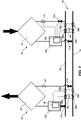
Fig. 4A is a schematic illustration of an alternative flow controller set in a flowing mode. -
Fig. 4B is a schematic illustration of the alternative flow controller ofFig. 4A set in a pumping mode. -
Fig. 5 is a block diagram of controlling of a local thermal energy consumer assembly. -
Fig. 6 is a block diagram of controlling of a local thermal energy generator assembly. - The present invention will now be described more fully hereinafter with reference to the accompanying drawings, in which currently preferred embodiments of the invention are shown. This invention may, however, be embodied in many different forms and should not be construed as limited to the embodiments set forth herein; rather, these embodiments are provided for thoroughness and completeness, and to fully convey the scope of the invention to the skilled person.
- In
Fig. 1 a district thermal energy distribution system 1 is illustrated. The district thermal energy distribution system 1 comprises athermal energy circuit 10 and a plurality ofbuildings 5. The plurality ofbuildings 5 are thermally coupled to thethermal energy circuit 10. Thethermal energy circuit 10 is arranged to circulate and store thermal energy in heat transfer liquid flowing through thethermal energy circuit 10. - The heat transfer liquid may comprise water. However, other heat transfer liquids may alternatively be used. Some non-limiting examples are ammonia, oils, alcohols and anti-freezing liquids, such as glycol. The heat transfer liquid may also comprise a mixture of two or more of the heat transfer liquids mentioned above. A specific mixture to be used is water mixed with an anti-freezing liquid.
- The
thermal energy circuit 10 comprises twoconduits conduits hot conduit 12 in thethermal energy circuit 10 is configured to allow heat transfer liquid of a first temperature to flow therethrough. Acold conduit 14 in thethermal energy circuit 10 is configured to allow heat transfer liquid of a second temperature to flow therethrough. The second temperature is lower than the first temperature. - In case heat transfer liquid is water (possibly with added anti-freezing liquid), a suitable temperature range for the hot heat transfer liquid is between 5 and 45°C and a suitable temperature range for the cold heat transfer liquid is between 0 and 40° C. A suitable temperature difference between the first and second temperatures is in the range of 5-16°C, preferably in the range of 7-12°C, more preferably 8-10°C.
- Preferably, the system is set to operate with a sliding temperature difference which varies depending on the climate. Preferably, the sliding temperature difference is fixed. Hence, the temperature difference may be to momentarily slide with a fixed temperature difference.
- The
hot conduit 12 and thecool conduit 14 are separate. Thehot conduit 12 and thecool conduit 14 may be parallelly arranged. Thehot conduit 12 and thecool conduit 14 may be arranged as closed loops of piping. Thehot conduit 12 and thecool conduit 14 are fluidly interconnected at thebuildings 5 for allowing of thermal energy transfer to and from thebuildings 5. This will be discussed more in detail further below. - The two
conduits thermal energy circuit 10 may be formed by plastic, composite, concrete, or metal pipes. According to one embodiment High Density Polyethylene (HDPE) pipes may be used. The pipes may be single wall pipes. The pipes may be un-insulated. According to one embodiment thethermal energy circuit 10 is mainly arranged in the ground. The ground will be used as thermal inertia of thethermal energy circuit 10. Hence, insulation of the piping gives no extra value. Exceptions are installation in cities with a very warm climate or cities with very cold climate. Here the inertia of the ground may be more harmful than good during critical parts of the year. Here insulation of the piping may be needed. - According to one embodiment the two
conduits thermal energy circuit 10 are dimensioned for pressures up to 1 MPa (10 bar). According to other embodiments the twoconduits thermal energy circuit 10 may be dimensioned for pressures up to 0.6 MPa (6 bar) or for pressures up to 1.6 MPa (16 bar). - A
building 5 comprise at least one of one or more local thermalenergy consumer assemblies 20 and one or more local thermalenergy generator assemblies 30. Hence, a building comprises at least one local thermalenergy consumer assembly 20 or at least one local thermalenergy generator assembly 30. Onespecific building 5 may comprise more than one local thermalenergy consumer assembly 20. Onespecific building 5 may comprise more than one local thermalenergy generator assembly 30. Onespecific building 5 may comprise both a local thermalenergy consumer assembly 20 and a local thermalenergy generator assembly 30. - The local thermal
energy consumer assembly 20 is acting as a thermal sink. Hence, the local thermalenergy consumer assembly 20 is arranged to remove thermal energy from thethermal energy circuit 10. Or in other words, the local thermalenergy consumer assembly 20 is arranged to transfer thermal energy from heat transfer liquid of thethermal energy circuit 10 to surroundings of the local thermalenergy consumer assembly 20. This is achieved by transfer thermal energy from heat transfer liquid taken from thehot conduit 12 to surroundings of the local thermalenergy consumer assembly 20, such that heat transfer liquid returned to thecold conduit 14 has a temperature lower than the first temperature and preferably a temperature equal to the second temperature. - The local thermal
energy generator assembly 30 is acting as a thermal source. Hence, the local thermalenergy generator assembly 30 is arranged to deposit thermal energy to thethermal energy circuit 10. Or in other words, the local thermalenergy generator assembly 30 is arranged to transfer thermal energy from its surroundings to heat transfer liquid of thethermal energy circuit 10. This is achieved by transfer thermal energy from surroundings of the local thermalenergy generator assembly 30 to heat transfer liquid taken from thecold conduit 12, such that heat transfer liquid returned to thehot conduit 12 has a temperature higher than the second temperature and preferably a temperature equal to the first temperature. - The one or more local thermal
energy consumer assemblies 20 may be installed in thebuildings 5 as local heaters for different heating needs. As a non-limiting example, a local heater may be arranged to deliver space heating or hot tap hot water preparation. Alternatively or in combination, the local heater may deliver pool heating or ice- and snow purging. Hence, the local thermalenergy consumer assembly 20 is arranged for deriving heat from heat transfer liquid of thehot conduit 12 and creates a cooled heat transfer liquid flow into thecold conduit 14. Hence, the local thermalenergy consumer assembly 20 fluidly interconnects the hot andcool conduits hot conduit 12 through the local thermalenergy consumer assembly 20 and then into thecool conduit 14 after thermal energy in the heat transfer liquid has been consumed by the local thermalenergy consumer assembly 20. The local thermalenergy consumer assembly 20 operates to draw thermal energy from thehot conduit 12 to heat thebuilding 5 and then deposits the cooled heat transfer liquid into thecool conduit 14. - The one or more local thermal
energy generator assemblies 30 may be installed indifferent buildings 5 as local coolers for different cooling needs. As an on-limiting example a local cooler may be arranged to deliver space cooling or cooling for freezers and refrigerators. Alternatively or in combination, the local cooler may deliver cooling for ice rinks and ski centers or ice- and snow making. Hence, the local thermalenergy generator assembly 30 is deriving cooling from heat transfer liquid of thecold conduit 14 and creates a heated heat transfer liquid flow into thehot conduit 12. Hence, the local thermalenergy generator assembly 30 fluidly interconnects the cold andhot conduits cold conduit 14 through the local thermalenergy generator assembly 30 and then into thehot conduit 12 after thermal energy has been generated into the heat transfer liquid by the local thermalenergy generator assembly 30. The local thermalenergy generator assembly 30 operates to extract heat from thebuilding 5 to cool thebuilding 5 and deposits that extracted heat into thehot conduit 12. - With reference to
Fig. 2 the function of the local thermalenergy consumer assembly 20 and the local thermalenergy generator assembly 30 will now be discussed. InFig. 2 one local thermalenergy consumer assembly 20 and one local thermalenergy generator assembly 30 are connected to thethermal energy circuit 10. Of course there might be more local thermal energy consumer assemblies or local thermal energy generator assemblies connected to thethermal energy circuit 10. - The local thermal
energy consumer assembly 20 comprises a thermal energyconsumer heat exchanger 22, aflow controller 100, and a consumer assembly pressuredifference determining device 26. - The consumer assembly pressure
difference determining device 26 is adapted to determine a consumer assembly local pressure difference, Δp1, of thethermal energy circuit 10. Δp1 is preferably measured in the vicinity to where the thermal energyconsumer heat exchanger 22 is connected to thethermal energy circuit 10. The consumer assembly pressuredifference determining device 26 may comprises a hot conduitpressure determining device 26a and a cold conduitpressure determining device 26b. The hot conduitpressure determining device 26a is arranged to be connected to thehot conduit 12 for measuring a consumer assembly local pressure, p1h, of heat transfer liquid of thehot conduit 12. The cold conduitpressure determining device 26b is arranged to be connected to thecold conduit 14 for measuring a consumer assembly local pressure, p1c, of heat transfer liquid of thecold conduit 14. The consumer assembly localpressure difference device 26 is arranged to determine the consumer assembly local pressure difference as a pressure difference between the consumer assembly local pressure of heat transfer liquid of thehot conduit 12 and the consumer assembly local pressure of heat transfer liquid of thecold conduit 14. The consumer assembly local pressure difference, Δp1, may hence be expressed as:
- Preferably, the consumer assembly local pressure of heat transfer liquid of the
hot conduit 12 is measured in the vicinity to where the thermal energyconsumer heat exchanger 22 is connected to thehot conduit 12. Preferably, the consumer assembly local pressure of heat transfer liquid of thecold conduit 14 is measured in the vicinity to where the thermal energyconsumer heat exchanger 22 is connected to thecold conduit 14. - The consumer assembly pressure
difference determining device 26 may be implemented as a hardware device, a software device, or as a combination thereof. The consumer assembly pressuredifference determining device 26 is arranged to generate a signal indicative of the consumer assembly local pressure difference, Δp1. - The thermal energy
consumer heat exchanger 22 is configured to be connected to thehot conduit 12 via theflow controller 100. Theflow controller 100 is selectively set in a pumping mode or in a flowing mode. Theflow controller 100 is selectively set in the pumping mode or in the flowing mode based on a consumer assembly local delivery differential pressure, Δp1dp,
consumer heat exchanger 22. This will be discussed in more detail below in connection with the more detailed disclosure of theflow controller 100 and in connection with the control of the local thermalenergy consumer assembly 20. - Upon set in the pumping mode the
flow controller 100 is configured to act as a pump for pumping heat transfer liquid from thehot conduit 12 into the thermal energyconsumer heat exchanger 22. Hence, upon theflow controller 100 being set in the pumping mode, heat transfer liquid from thehot conduit 12 is pumped into the thermal energyconsumer heat exchanger 22. Upon set in flowing mode theflow controller 100 is configured to act as a flow regulator for allowing heat transfer liquid from thehot conduit 12 to flow into the thermal energyconsumer heat exchanger 22. Hence, upon theflow controller 100 being set in the flowing mode, heat transfer liquid from thehot conduit 12 is allowed to flow into the thermal energyconsumer heat exchanger 22. Again, the choice of allowing heat transfer liquid from thehot conduit 12 to flow into the thermal energyconsumer heat exchanger 22 or pumping heat transfer liquid from thehot conduit 12 into the thermal energyconsumer heat exchanger 22, is made based on the consumer assembly local delivery differential pressure, Δp1dp. - With reference to
Figs 3 ,4a and4b embodiments of theflow controller 100 will now be described in greater detail. InFig. 3 an embodiment of theflow controller 100 is schematically illustrated. InFigs 4A and4B an alternative embodiment of theflow controller 100 is schematically illustrated. - Below first common features of both the
flow controller 100 as illustrated inFig. 3 and thealternative flow controller 100 as illustrated inFigs 4A and4B will be discussed. Thereafter specific features of the twoalternative flow controllers 100 will be discussed. - The
flow controller 100 comprises aninlet 102 for heat transfer liquid, anoutlet 103 for heat transfer liquid, apump assembly 110 arranged between theinlet 102 and theoutlet 103, aflow regulator assembly 120 arranged between theinlet 102 and theoutlet 103, and amode controller 130. - In may be said that the
flow controller 100 is configured to be connected in between a first and a second reservoir of fluid. Theinlet 102 is configured to be connected to the first reservoir. Theoutlet 103 is configured to be connected to the second reservoir. - The
pump assembly 110, upon being active, is configured to pump heat transfer liquid through theflow controller 100 from theinlet 102 to theoutlet 103. Thepump assembly 110 may comprise apumping wheel 114 and anelectric motor 112. Theelectric motor 112 is configured to, upon thepump assembly 110 being active, turn thepumping wheel 114 and thereby inducing pumping action to thepump assembly 110. Hence, thepump wheel 114 of thepump assembly 110 is configured to provide pump action. Moreover, thepump assembly 110 may also be arranged such that the flow rate of heat transfer liquid through theflow controller 100 may be controlled. - The
flow regulator assembly 120, upon being active, is configured to allow heat transfer liquid to flow through theflow controller 100 from theinlet 102 to theoutlet 103. Moreover, upon being active, theflow regulator assembly 120 is further configured to be selectively set in an electricity generating mode or in a flow decreasing mode. - Upon being set in the electricity generating mode the
flow regulator assembly 120 is configured to generate electricity by transforming flow energy of heat transfer liquid flowing through theflow controller 100 into electricity. Theflow regulator assembly 120 may comprise aturbine wheel 124 to provide hydro electrical generation and agenerator 122 configured to be connected to theturbine wheel 124. Thegenerator 122 is configured to generate electricity upon theturbine wheel 124 being turned. Theturbine wheel 124 being turned by a flow of heat transfer liquid flowing through theflow controller 100 upon theflow regulator assembly 120 being set in the electricity generating mode. Hence, theturbine wheel 124 of theflow regulator assembly 120 is configured to provide hydro electrical generation. - As mentioned above, the
flow regulator assembly 120 may additionally be set in a flow decreasing mode. Upon theflow regulator assembly 120 being set in the flow decreasing mode, the flow through theflow controller 100 may be regulated by driving theturbine wheel 124, now acting as a deaccelerating means, so that thewheel 124 is rotating against the fluid flow direction. Thewheel 124 may be rotated at a predetermined frequency. By rotating thewheel 124 against the fluid flow direction the flow of fluid through the flow controller may be slowed down. Different predetermined frequencies correspond to different flows through theflow controller 100. Hence, the flow throughflow controller 100 may be deaccelerated by rotating thewheel 124 against the direction of flow through theflow controller 100. - The
mode controller 130 is configured to selectively set theflow controller 100 in the pumping mode or in the flowing mode. The flowing mode comprising two alternative modes, an electricity generating mode and a flow decreasing mode. In the pumping mode theflow controller 100 is acting as a pump. In the flowing mode theflow controller 100 is acting as a flow regulator. In the electricity generating mode theflow regulator 100 is acting as a flow regulator and at the same time as a generator for electricity. In the flow decreasing mode theflow regulator 100 is acting as a flow regulator and at the same time slowing down the flow of fluid through theflow controller 100. Hence, theflow controller 100 is configured to selectively act as a pump or as a flow regulator. Theflow controller 100 is configured to, upon acting as a pump, pump heat transfer liquid through theflow controller 100. Theflow controller 100 is configured to, upon acting as a flow regulator, allow heat transfer liquid to flow through theflow controller 100. Upon being set in the pumping mode, themode controller 130 is configured to deactivate theflow regulator assembly 120 and to activate thepump assembly 110. Upon being set in the flowing mode, themode controller 130 is configured to deactivate thepump assembly 110 and to activate theflow regulator assembly 120. - In the present thermal energy circuit 10 a differential pressure between heat transfer liquid in hot and
cold conduits cold conduits - In case the
flow controller 100 is comprised in the local thermalenergy consumer assembly 20, see above, heat transfer liquid is to be transferred from thehot conduit 12 to thecold conduit 14. Depending on the variating differential pressure between the hot andcold conduits thermal energy circuit 10 sometimes heat transfer liquid need to be pumped from thehot conduit 12 to thecold conduit 14 and sometimes heat transfer liquid need to be allowed to flow fromhot conduit 12 to thecold conduit 14. More precisely, in case the consumer assembly local delivery differential pressure, Δp1dp, is negative theflow controller 100 is configured to allow a flow of heat transfer liquid to flow through theflow controller 100. Hence, themode controller 130 is configured to set theflow controller 100 in the flowing mode. Further, the consumer assembly local delivery differential pressure, Δp1dp, is positive theflow controller 100 is configured to pump a flow of heat transfer liquid from thehot conduit 12 to thecold conduit 14. Hence, themode controller 130 is configured to set theflow controller 100 in the pumping mode. - Further, in case the
flow controller 100 is comprised in the local thermalenergy generator assembly 30, see below, heat transfer liquid is to be transferred from thecold conduit 14 to thehot conduit 12. Depending on the variating differential pressure between the hot andcold conduits thermal energy circuit 10 sometimes heat transfer liquid need to be pumped from thecold conduit 14 to thehot conduit 12 and sometimes heat transfer liquid need to be allowed to flow fromcold conduit 14 to thehot conduit 12. More precisely, in case a generator assembly local delivery differential pressure, Δp2dp, (see below for more detail on the generator assembly local delivery differential pressure) is positive theflow controller 100 is configured to allow a flow of heat transfer liquid to flow through theflow controller 100. Hence, themode controller 130 is configured to set theflow controller 100 in the flowing mode. Further, the generator assembly local delivery differential pressure, Δp2dp, is negative theflow controller 100 is configured to pump a flow of heat transfer liquid from thecold conduit 14 to thehot conduit 12. Hence, themode controller 130 is configured to set theflow controller 100 in the pumping mode. - The
mode controller 130 is configured to receive a signal indicative on a pressure difference between heat transfer liquid of the hot andcold conduits mode controller 130 may be fully hardware implemented. Alternatively, themode controller 130 may be fully software implemented. Yet alternatively, themode controller 130 may be a combined hardware and software implementation. The software portions of themode controller 130 may be run on a processing unit. Themode controller 130 is configured to set theflow controller 100 in the pumping mode or the flowing mode based on the signal indicative on the pressure difference between heat transfer liquid in the hot andcold conduits - The
mode controller 130 may be configured to set theflow controller 100 in the pumping mode, or the electricity generating mode, or the flow decreasing mode based on a signal indicative on the pressure difference between the fluid at theinlet 102 and the fluid at theoutlet 103. If so, themode controller 130 is configured to set theflow controller 100 in the pumping mode in case the signal is indicative of that the pressure of the fluid at theinlet 102 is equal or lower than the pressure at theoutlet 103. Moreover, if so, themode controller 130 is configured to set theflow controller 100 in the electricity generating mode or in the flow decreasing mode in case the signal is indicative of that the pressure of the fluid at theinlet 2 is higher than the pressure at theoutlet 103. The choice of setting the flow controller in the electricity generating mode or in the flow decreasing mode is based on a pressure difference between a pressure of the fluid at theinlet 102 and a pressure of the fluid at theoutlet 103. For relatively low pressure differences themode controller 130 is configured to set theflow controller 100 in the electricity generating mode and for relatively low pressure differences themode controller 130 is configured to set the flow controller in the flow decreasing mode. The value at which the flow decreasing mode is to chosen instead of the electricity generating mode depend on the actual flow rate through theflow controller 100. In case of the flow rate need to be decreased due to the relatively high pressure difference themode controller 130 is configured to set theflow controller 100 in the flow decreasing mode. - The
mode controller 130 may also be configured to control the flow rate of heat transfer liquid through theflow controller 100. Accordingly, themode controller 130 may also be configured to control thepump assembly 110 such that the flow rate of heat transfer liquid pumped by thepump assembly 110 is controlled. This may be done by regulating a rotation frequency of apump wheel 114 of thepump assembly 100. Moreover, themode controller 130 may also be configured to control theflow regulator assembly 120 such that the flow rate of heat transfer liquid flowing through theflow regulator assembly 120 is controlled. This may be done, as have been discussed above, by regulating the rotation frequency of thewheel 124 - With reference to
Fig. 3 theflow controller 100 may further comprise awheel 150. Thewheel 150 is selectively operable as thepump wheel 114 of thepump assembly 110 and as aturbine wheel 124 of theflow regulator assembly 120. Upon theflow controller 100 is set in the pumping mode thewheel 150 is selectively operable as thepump wheel 114. Upon theflow controller 100 is set in the flowing mode thewheel 150 is selectively operable as theturbine wheel 124. Upon theflow controller 100 is set in the flow decreasing mode thewheel 150 is selectively operable as a deaccelerating means. Hence, in the pumping mode thewheel 150 is acting as thepumping wheel 124 and is configured to be connected to theelectric motor 112. Moreover, in the flowing mode thewheel 150 is acting as theturbine wheel 124 and is configured to be connected to thegenerator 122. Furthermore, in the flow decreasing mode thewheel 150 is acting as a deaccelerating means and is configured to be connected to theelectric motor 112. - With reference to
Figs 4A and4B theflow controller 100 may comprise afirst flow channel 116 for heat transfer liquid and asecond flow channel 126 for heat transfer liquid. Thefirst flow channel 116 forming part of the pump assembly 1110. Thesecond flow channel 126 forming part of theflow regulator assembly 120. Theflow controller 100 may further comprise aflow director 160. Theflow director 160 is configured to be controlled by themode controller 130. Upon theflow controller 100 is set in the pumping mode, theflow director 160 is configured to direct flow of heat transfer liquid through thefirst flow channel 116 and block flow of heat transfer liquid through thesecond channel 126. This is illustrated inFig 4B . Upon theflow controller 100 is set in the flowing mode, theflow director 160 is configured to direct flow of heat transfer liquid through thesecond flow channel 126 and block flow of heat transfer liquid through thefirst channel 116. This is illustrated inFig 4A . Theflow director 160 may be embodied in many different ways. According to a non-limiting example, theflow director 160 may comprise a sliding block configured to selectively block flow of heat transfer liquid through the first andsecond flow channels flow director 160 is blocking one of the first andsecond flow channels - The thermal energy
consumer heat exchanger 22 is further connected to thecold conduit 14 for allowing return of heat transfer liquid from the thermal energyconsumer heat exchanger 22 to thecold conduit 14. - The thermal energy
consumer heat exchanger 22 is arranged to transfer thermal energy from heat transfer liquid to surroundings of the thermal energyconsumer heat exchanger 22. The heat transfer liquid returned to thecold conduit 14 has a temperature lower than the first temperature. Preferably, thermal energyconsumer heat exchanger 22 is controlled such that the temperature of the heat transfer liquid returned to thecold conduit 14 is equal to the second temperature. - The local thermal
energy consumer assembly 20 may further comprise a pair of consumerassembly service valves assembly service valves consumer heat exchanger 22 and theflow controller 100 to/from thethermal energy circuit 10. - The local thermal
energy consumer assembly 20 may further comprise a consumer assembly hot conduittemperature determining device 25a and a consumer assembly cold conduit temperature determining device 25b.The consumer assembly hot conduittemperature determining device 25a is arranged to be connected to thehot conduit 12 for measuring a consumer assembly local temperature, t1h, of heat transfer liquid of thehot conduit 12. The consumer assembly cold conduittemperature determining device 25b is arranged to be connected to thecold conduit 14 for measuring a consumer assembly local temperature, t1c, of the heat transfer liquid of thecold conduit 14. The consumer assembly hot conduittemperature determining device 25a and the consumer assembly cold conduittemperature determining device 25b are connected to theflow controller 100 for communicating t1h and t1c thereto. - The local thermal
energy consumer assembly 20 may further comprise a consumer assembly outlettemperature determining device 27. The consumer assembly outlettemperature determining device 27 is arranged to be connected to a return conduit connecting the outlet of the thermal energyconsumer heat exchanger 22 to thecold conduit 14. The consumer assembly outlettemperature determining device 27 is arranged to measure an outlet temperature, tche, of heat transfer liquid exiting the outlet of the thermal energyconsumer heat exchanger 22 and being returned to thecold conduit 14. The consumer assembly outlettemperature determining device 27 is connected to theflow controller 100 for communicating tche thereto. - In connection with
Fig. 5 , an exemplified embodiment on how themode controller 130 of theflow controller 100 is arranged to control the local thermalenergy consumer assembly 20 will be discussed. -
- 1. Receiving S500 a start signal by the
mode controller 100. The start signal indicating that the local thermalenergy consumer assembly 20 shall start working for exhaling thermal energy to its surroundings. The start signal may e.g. be issued by a thermostat (not shown) located in the building wherein the local thermalenergy consumer assembly 20 is situated. - 2. Determining S502 the consumer assembly local delivery differential pressure, Δp1dp, according to the following:

consumer heat exchanger 22. - 3. In case Δp1dp is a positive value:
- a. Setting S504 the
flow controller 100 in the pumping mode. - b. Ramping up S506 the flow rate of the
pump assembly 110 so that a predetermined flow rate through the thermal energyconsumer heat exchanger 22 is achieved. - c. Switching to normal operation mode of the local thermal energy consumer assembly at pump operation, see below.
- a. Setting S504 the
- 4. In case Δp1dp is a negative value:
- a. Setting S512 the
flow controller 100 in the flowing mode. - b. Regulating S514 a flow rate through the
flow controller 100 so that a predetermined flow rate through the thermal energyconsumer heat exchanger 22 is achieved. - c. Switching to normal operation mode of the local thermal energy consumer assembly at flow operation, see below.
- a. Setting S512 the
-
- 1. Controlling S508 the
pump assembly 110 such that the flow rate of heat transfer liquid through the thermal energyconsumer heat exchanger 22 is set such that a differential temperature, Δtche=t1h- tche, over the thermal energyconsumer heat exchanger 22 is kept at a predetermined value. A suitable predetermined differential temperature is in the range of 5-16°C, preferably in the range of 7-12°C, more preferably 8-10°C. - 2. Determining S510 the consumer assembly local delivery differential pressure, Δp1dp.
- 3. In case Δp1dp is a positive value; return to point 1. above under "Normal operation mode of the local thermal energy consumer assembly at pump operation".
- 4. In case Δp1dp is a negative value:
- a. Go to
point 4, above under "Starting of the local thermal energy consumer assembly". - b. Stopping the
pump assembly 110 by sending a stop signal thereto from themode controller 130.
- a. Go to
-
- 1. Controlling S516 the
flow regulator assembly 120 such that the flow rate of heat transfer liquid through the thermal energyconsumer heat exchanger 22 is set such that the differential temperature, Δtche=t1h- tche, over the thermal energyconsumer heat exchanger 22 is kept at a predetermined value. A suitable predetermined differential temperature is in the range of 5-16°C, preferably in the range of 7-12°C, more preferably 8-10°C. - 2. Determining S518 the consumer assembly local delivery differential pressure, Δp1dp.
- 3. In case Δp1dp is still a negative value; return to point 1. above under "Normal operation mode of the local thermal energy consumer assembly at flow operation".
- 4. In case Δp1dp is a negative value:
- a. Go to point 3, above under "Starting of the local thermal energy consumer assembly".
- b. Stopping the
flow regulator assembly 120 by sending a stopping signal thereto from themode controller 130.
- With reference to
Fig. 2 , the local thermalenergy generator assembly 30 comprises a thermal energygenerator heat exchanger 32, aflow controller 100, and a generator assembly pressuredifference determining device 26. - The generator assembly pressure
difference determining device 36 is adapted to determine a generator assembly local pressure difference, Δp2, of thethermal energy circuit 10. Δp2 is preferably measured in the vicinity to where the thermal energygenerator heat exchanger 32 is connected to thethermal energy circuit 10. The generator assembly pressuredifference determining device 36 may comprises a hot conduitpressure determining device 36a and a cold conduitpressure determining device 36b. The hot conduitpressure determining device 36a is arranged to be connected to thehot conduit 12 for measuring a generator assembly local pressure, p2h, of heat transfer liquid of thehot conduit 12. The cold conduitpressure determining device 36b is arranged to be connected to thecold conduit 14 for measuring a generator assembly local pressure, p2c, of heat transfer liquid of thecold conduit 14. The generator assembly localpressure difference device 36 is arranged to determine the generator assembly local pressure difference as a pressure difference between the generator assembly local pressure of heat transfer liquid of thehot conduit 12 and the generator assembly local pressure of heat transfer liquid of thecold conduit 14. The generator assembly local pressure difference, Δp2, may hence be expressed as:
- Preferably, the generator assembly local pressure of heat transfer liquid of the
hot conduit 12 is measured in the vicinity to where the thermal energygenerator heat exchanger 32 is connected to thehot conduit 12. Preferably, the generator assembly local pressure of heat transfer liquid of thecold conduit 14 is measured in the vicinity to where the thermal energygenerator heat exchanger 32 is connected to thecold conduit 14. - The generator assembly pressure
difference determining device 36 may be implemented as a hardware device, a software device, or as a combination thereof. The generator assembly pressuredifference determining device 36 is arranged to generate a signal indicative of the generator assembly local pressure difference, Δp2. - The thermal energy
generator heat exchanger 32 is connected to thecold conduit 14 via theflow controller 100. Theflow controller 100 is selectively set in the pumping mode or in the flowing mode. Theflow controller 100 is selectively set in the pumping mode or in the flowing mode based on the generator assembly local delivery pressure difference, Δp2dp,
generator heat exchanger 32. This was discussed in more detail in connection with the more detailed disclosure of theflow controller 100 above and will be discussed in even more detail below in connection with the control of the local thermalenergy generator assembly 30. - Upon set in the pumping mode the
flow controller 100 is configured to act as a pump for pumping heat transfer liquid from thecold conduit 14 into the thermal energygenerator heat exchanger 32. Hence, upon theflow controller 100 being set in the pumping mode, heat transfer liquid from thecold conduit 14 is pumped into the thermal energygenerator heat exchanger 32. Upon set in flowing mode theflow controller 100 is configured to act as a flow regulator for allowing heat transfer liquid from thecold conduit 14 to flow into the thermal energygenerator heat exchanger 32. Hence, upon theflow controller 100 being set in the flowing mode, heat transfer liquid from thecold conduit 14 is allowed to flow into the thermal energygenerator heat exchanger 32. Again, the choice of allowing heat transfer liquid from thecold conduit 14 to flow into the thermal energygenerator heat exchanger 32 or pumping heat transfer liquid from thecold conduit 14 into the thermal energygenerator heat exchanger 32, is made based on the generator assembly local delivery differential pressure, Δp2dp. - The thermal energy
generator heat exchanger 32 is further connected to thehot conduit 12 for allowing return of heat transfer liquid from the thermal energygenerator heat exchanger 32 to thehot conduit 12. - The thermal energy
generator heat exchanger 32 is arranged to transfer thermal energy from its surroundings to heat transfer liquid. The heat transfer liquid returned tohot conduit 12 has a temperature higher than the second temperature. Preferably, thermal energygenerator heat exchanger 32 controlled such that the temperature of the heat transfer liquid returned to thehot conduit 12 is equal to the first temperature. - The local thermal
energy generator assembly 30 may further comprise a pair of generatorassembly service valves assembly service valves generator heat exchanger 32 and theflow controller 100 to/from thethermal energy circuit 10. - The local thermal
energy generator assembly 30 may further comprise a generator assembly hot conduittemperature determining device 35a and a generator assembly cold conduit temperature determining device 35b.The generator assembly hot conduit temperature determining device is arranged to be connected to thehot conduit 12 for measuring a generator assembly local temperature, t2h, of heat transfer liquid of thehot conduit 12. The generator assembly cold conduit temperature determining device is arranged to be connected to thecold conduit 14 for measuring a generator assembly local temperature, t2c, of the heat transfer liquid of thecold conduit 14. The generator assembly hot conduittemperature determining device 35a and the generator assembly cold conduittemperature determining device 35b are connected to theflow controller 100 for communicating t1h and t1c thereto. - The local thermal
energy generator assembly 30 may further comprise a generator assembly outlettemperature determining device 37. The generator assembly outlettemperature determining device 37 is arranged to be connected to a return conduit connecting the outlet of the thermal energygenerator heat exchanger 32 to thehot conduit 12. The generator assembly outlettemperature determining device 37 is arranged to measure an outlet temperature tghe, of heat transfer liquid exiting the outlet of the thermal energygenerator heat exchanger 32 and being returned to thehot conduit 12. The generator assembly outlettemperature determining device 37 is connected to theflow controller 100 for communicating tghe thereto. - In connection with
Fig. 6 , an exemplified embodiment on how themode controller 130 of theflow controller 100 is arranged to control the local thermalenergy generator assembly 30 will discussed. -
- 1. Receiving S600 a start signal by the
mode controller 130. The start signal indicating that the local thermalenergy generator assembly 30 shall start working for inhaling thermal energy from its surroundings. The start signal may e.g. be issued by a thermostat (not shown) located in the building wherein the local thermalenergy generator assembly 30 is situated. - 2. Determining S602 the generator assembly local delivery differential pressure, Δp2dp, according to the following:

generator heat exchanger 32. - 3. In case Δp2dp is a negative value:
- a. Setting S604 the
flow controller 100 in the pumping mode. - b. Ramping up S606 the flow rate of the
pump assembly 110 so that a predetermined flow rate through the thermal energygenerator heat exchanger 32 is achieved. - c. Switching to normal operation mode of the local thermal energy generator assembly at pump operation, see below.
- a. Setting S604 the
- 4. In case Δp2dp is a positive value:
- a. Setting S612 the
flow controller 100 in the flowing mode. - b. Regulating S514 a flow rate through the
flow controller 100 so that a predetermined flow rate through the thermal energygenerator heat exchanger 32 is achieved. - c. Switching to normal operation mode of the local thermal energy generator assembly at flow operation, see below.
- a. Setting S612 the
-
- 1. Controlling S608 the
pump assembly 110 such that the flow rate of heat transfer liquid through the thermal energygenerator heat exchanger 32 is set such that a differential temperature, Δtghe=t2h- tghe, over the thermal energyconsumer heat exchanger 22 is kept at a predetermined value. A suitable predetermined differential temperature is in the range of 5-16°C, preferably in the range of 7-12°C, more preferably 8-10°C. - 2. Determining S610 the generator assembly local delivery differential pressure, Δp2dp.
- 3. In case Δp2dp is a negative value; return to point 1. above under "Normal operation mode of the local thermal energy generator assembly at pump operation".
- 4. In case the Δp2dp is a positive value:
- a. Go to
point 4, above under "Starting of the local thermal energy generator assembly". - b. Stopping the
pump assembly 110 by sending a stop signal thereto from themode controller 130.
- a. Go to
-
- 1. Controlling S616 the
flow regulator assembly 120 such that the flow rate of heat transfer liquid through the thermal energygenerator heat exchanger 32 is set such that the differential temperature, Δtghe=t2h- tghe, over the thermal energygenerator heat exchanger 32 is kept at a predetermined value. A suitable predetermined differential temperature is in the range of 5-16°C, preferably in the range of 7-12°C, more preferably 8-10°C. - 2. Determining S618 the generator assembly local delivery differential pressure, Δp2dp.
- 3. In case Δp2dp is still a positive value; return to point 1. above under "Normal operation mode of the local thermal energy generator assembly at flow operation".
- 4. In case Δp2dp is a positive value:
- a. Go to point 3, above under "Starting of the local thermal energy generator assembly".
- b. Stopping the
flow regulator assembly 120 by sending a stopping signal thereto from themode controller 130.
- Accordingly, a local thermal
energy consumer assembly 20 and a local thermalenergy generator assembly 30 to be connected to athermal energy circuit 10 comprising a hot and acold conduit energy consumer assembly 20 is connected via aflow controller 100 to thehot conduit 12. The local thermalenergy generator assembly 30 is connected via aflow controller 100 to thecold conduit 14. Theflow controller 100 is selectively set in pumping mode or a flowing mode based on a local pressure difference between heat transfer liquid of the hot andcold conduits cold conduits energy consumer assemblies 20 and/or one or more thermalenergy generator assemblies 30. - Accordingly, the district thermal energy distribution system 1 comprises a
thermal energy circuit 10 comprising the hot andcold conduit consumer heat exchangers 22 and one or more thermal energygenerator heat exchangers 32. In accordance with what has been disclosed above the district thermal energy distribution system 1 may comprise a thermal energyconsumer heat exchanger 22 connected to thehot conduit 12 via aflow controller 100. Theflow controller 100 is selectively set in pumping mode or a flowing mode based on the local pressure difference between heat transfer liquid of the hot andcold conduits consumer heat exchanger 22 selectively connected to thehot conduit 12 via a thermal energy consumer valve (not shown) or a thermal energy consumer pump (not shown). The use of the thermal energy consumer valve or the thermal energy consumer pump for letting heat transfer liquid to flow through the thermal energyconsumer heat exchanger 22 is based on the local pressure difference between heat transfer liquid of the hot andcold conduits generator heat exchanger 32 connected to thecold conduit 14 via aflow controller 100. Theflow controller 100 is selectively set in pumping mode or a flowing mode based on the local pressure difference between heat transfer liquid of the hot andcold conduits generator heat exchanger 32 selectively connected to thecold conduit 14 via a thermal energy generator valve (not shown) or a thermal energy generator pump (not shown). The use of the thermal energy generator valve or the thermal energy generator pump for letting heat transfer liquid to flow through the thermal energygenerator heat exchanger 32 is based on the local pressure difference between heat transfer liquid of the hot andcold conduits - Preferably, the demand to inhale or exhale heat using the thermal energy
consumer heat exchangers 22 and the thermal energygenerator heat exchangers 32 is made at a defined temperature difference. A temperature difference of 8-10°C corresponds to optimal flows through the thermal energyconsumer heat exchangers 22 and the thermal energygenerator heat exchangers 32. - The local pressure difference between the hot and
cold conduits thermal energy circuit 10. Especially, the local pressure difference between the hot andcold conduits cold conduits generator assembly generator heat exchanger generator assembly generator heat exchanger generator assemblies flow controllers 100 may be based on frequency controlled circulation pumps. - The basic idea of the district thermal energy distribution system 1 is based on the insight by the inventors that modern day cities by them self provide thermal energy that may be reused within the city. The reused thermal energy may be picked up by the district thermal energy distribution system 1 and be used for e.g. space heating or hot tap water preparation. Moreover, increasing demand for space cooling will also be handled within the district thermal energy distribution system 1. Within the district thermal energy distribution system 1
buildings 5 within the city are interconnected and may in an easy and simple way redistribute low temperature waste energy for different local demands. Amongst other the district thermal energy distribution system will provide for: - Minimizing the use of primary energy due to optimal re-use of energy flows inside the city.
- Limiting the need for chimneys or firing places inside the city, since the need for locally burning gas or other fuels will be reduced.
- Limiting the need for cooling towers or cooling convectors inside the city, since excess heat produced by cooling devices may be transported away and reused within the district thermal energy distribution system 1.
- Hence, the district thermal energy distribution system 1 provide for a smart duel use of thermal energy within a city. When integrated into a city the district thermal energy distribution system 1 provide make use of low level thermal energy waste in both heating and cooling applications within the city. This will reduce the primary energy consumption of a city by eliminating the need for a gas grid or a district heating grid and a cooling grid in city.
- The district thermal energy distribution system 1 may comprise a
thermal server plant 2. Thethermal server plant 2 functions as an external thermal source and/or thermal sink. The function of thethermal server plant 2 is to maintain the temperature difference between the hot andcold conduits thermal energy circuit 10. That is, thethermal server plant 2 may be used for balancing the district thermal energy distribution system 1 such that when thethermal energy circuit 10 reaches a temperature end point thethermal server plant 2 is arranged to inhale or exhale thermal energy to/from thethermal energy circuit 10. In winter time, when there is higher probability that thehot conduit 12 reaches its' lowest temperature end point, thethermal server plant 2 is used for adding thermal energy to thethermal energy circuit 10. In summer time, when there is higher probability that the cold conduit reaches its' highest temperature end point, thethermal server plant 2 is used to subtract thermal energy from thethermal energy circuit 10. - The person skilled in the art realizes that the present invention by no means is limited to the preferred embodiments described above. On the contrary, many modifications and variations are possible within the scope of the appended claims.
- For example, the
flow controller 100 may further comprise abattery 140. Thebattery 140 may be configured to store electricity generated by theflow regulator assembly 120 upon being in the electricity generating mode. Theelectric motor 112 may be configured to at least partly be powered by the electricity stored in thebattery 140. Themode controller 130 may at least party be configured to be powered by the electricity stored in thebattery 140. - Moreover, the
electric motor 112 may be configured to act as thegenerator 122 upon theflow controller 100 is set in the electricity generating mode. Upon being set in the pumping mode theelectric motor 112 is configured to be supplied by electricity. Themode controller 130 may be configured to control the supply of electricity to theelectric motor 112. When being applied by electricity theelectric motor 112 is configured to turn thewheel 150 now acting as thepumping wheel 114 or as the deaccelerating means. Upon being set in the flowing mode theelectric motor 112 may be configured to act as thegenerator 122. When theelectric motor 112 is acting as thegenerator 122 turning of thewheel 150 now acting as theturbine wheel 114 induce thegenerator 122 to generate electricity. In accordance with the above, the generated electricity may be stored in thebattery 140. The electricity stored in thebattery 140 may then later be used for powering theelectric motor 112 when being set in the pumping mode or in the flow decreasing mode. - Further, in the in
Fig. 2 shown embodiment the pressuredifference determining devices 26; 36 are two physically different pressure difference determining devices. However, according to another embodiment one specific local thermalenergy consumer assembly 20 and one specific local thermalenergy generator assembly 30 may share the same pressure difference determining device. Hence, pressuredifference determining devices 26; 36 may physically be the same pressure difference determining device. According to a further embodiment two specific local thermalenergy consumer assemblies 20 may share the same pressure difference determining device. According to a yet another embodiment two specific local thermalenergy generator assemblies 30 may share the same pressure difference determining device - Additionally, variations to the disclosed embodiments can be understood and effected by the skilled person in practicing the claimed invention.
Claims (15)
- A local thermal energy consumer assembly (20), arranged to be connected to a thermal energy circuit (10) comprising a hot conduit (12) configured to allow heat transfer liquid of a first temperature to flow therethrough, and a cold conduit (14) configured to allow heat transfer liquid of a second temperature to flow therethrough, the second temperature is lower than the first temperature, the local thermal energy consumer assembly (20) comprising:a consumer assembly pressure difference determining device (26) adapted to determine a consumer assembly local pressure difference, Δp1, of the thermal energy circuit (10);a thermal energy consumer heat exchanger (22); anda flow controller (100),wherein the thermal energy consumer heat exchanger (22) is arranged to be connected to the hot conduit (12) via the flow controller (100),wherein the thermal energy consumer heat exchanger (22) is further arranged to be connected to the cold conduit (14) for allowing return of heat transfer liquid from the thermal energy consumer heat exchanger (22) to the cold conduit (14), andwherein the thermal energy consumer heat exchanger (22) is arranged to transfer thermal energy from heat transfer liquid to surroundings of the thermal energy consumer heat exchanger (22), such that heat transfer liquid returned to the cold conduit (14) has a temperature lower than the first temperature and preferably a temperature equal to the second temperaturecharacterized in that the flow controller (100) comprises a mode controller (130) configured to, based on Δp1, selectively set the flow controller (100) in a pumping mode or in a flowing mode, wherein upon set in the pumping mode the flow controller (100) is configured to act as a pump for pumping heat transfer liquid from the hot conduit (12) into the thermal energy consumer heat exchanger (22), and wherein upon set in flowing mode the flow controller (100) is configured to act as a flow regulator for allowing heat transfer liquid from the hot conduit (12) to flow into the thermal energy consumer heat exchanger (22).
- The local thermal energy consumer assembly (20) according to claim 1, wherein the mode controller (130) is configured to set the flow controller (100) in the pumping mode in case Δp1 is indicative of that a consumer assembly local pressure of heat transfer liquid in the hot conduit (12) is lower than a consumer assembly local pressure of heat transfer liquid in the cold conduit (14), and wherein the mode controller (130) is configured to set the flow controller (100) in the flowing mode in case Δp1 is indicative of that the consumer assembly local pressure of heat transfer liquid in the hot conduit (12) is higher than the consumer assembly local pressure of heat transfer liquid in the cold conduit (14).
- The local thermal energy consumer assembly (20) according to claim 1 or 2, wherein the flow controller (100) further comprises:an inlet (102) for heat transfer liquid;an outlet (103) for heat transfer liquid;a pump assembly (110) arranged between the inlet (102) and the outlet (103) and configured to pump heat transfer liquid through the flow controller (100) from the inlet (102) to the outlet (103);a flow regulator assembly (120) arranged between the inlet (102) and the outlet (103) and configured to allow the heat transfer liquid flow through the flow controller (100) from the inlet (102) to the outlet (103) and to generate electricity by transforming flow energy of heat transfer liquid flowing through the flow controller (100) into electricity;wherein upon being set in the pumping mode, the mode controller (130) is configured to activate the pump assembly (110) and to deactivate the flow regulator assembly (120);wherein upon being set in the flowing mode, the mode controller (130) is configured to deactivate the pump assembly (110) and to activate the flow regulator assembly (120).
- The local thermal energy consumer assembly (20) according to claim 3, wherein the flow controller (100) further comprises a wheel (150), wherein the wheel (150) is selectively operable as a pump wheel (114) of the pump assembly (110) to provide pump action upon the flow controller (100) is set in the pumping mode and as a turbine wheel (124) of the flow regulator assembly (120) to provide hydro electrical generation upon the flow controller (100) is set in the flowing mode.
- The local thermal energy consumer assembly (20) according to claim 3, wherein the flow controller (100) further comprises a first flow channel (116) for the heat transfer liquid and a second flow channel (126) for the heat transfer liquid, wherein the first flow channel (116) forming part of the pump assembly (110) and the second flow channel (126) forming part of the flow regulator assembly (120).
- A local thermal energy generator assembly (30), arranged to be connected to a thermal energy circuit (10) comprising a hot conduit (12) configured to allow heat transfer liquid of a first temperature to flow therethrough, and a cold conduit (14) configured to allow heat transfer liquid of a second temperature to flow therethrough, the second temperature is lower than the first temperature, the local thermal energy generator assembly comprising:a generator assembly pressure difference determining device (36) adapted to determine a generator assembly local pressure difference, Δp2, of the thermal energy circuit (10);a thermal energy generator heat exchanger (32); anda flow controller (100),wherein the thermal energy generator heat exchanger (32) is arranged to be connected to the cold conduit (14) via the flow controller (100),wherein the thermal energy generator heat exchanger (32) is further arranged to be connected to the hot conduit (12) for allowing return of heat transfer liquid from the thermal energy generator heat exchanger (32) to the hot conduit (12), andwherein the thermal energy generator heat exchanger (32) is arranged to transfer thermal energy from its surroundings to heat transfer liquid, such that the heat transfer liquid returned to hot conduit (12) has a temperature higher than the second temperature and preferably a temperature equal to the first temperaturecharacterized in that the flow controller (100) comprises a mode controller (130) configured to, based on Δp2, selectively set the flow controller (100) in a pumping mode or in a flowing mode, wherein upon set in the pumping mode the flow controller (100) is configured to act as a pump for pumping heat transfer liquid from the cold conduit (14) into the thermal energy generator heat exchanger (32), and wherein upon set in flowing mode the flow controller (100) is configured to act as a flow regulator for allowing heat transfer liquid from the cold conduit (14) to flow into the thermal energy generator heat exchanger (32).
- The local thermal energy generator assembly (30) according to claim 6, wherein the mode controller (130) is configured to set the flow controller (100) in the pumping mode in case Δp2 is indicative of that a generator assembly local pressure of heat transfer liquid in the cold conduit (14) is lower than a generator assembly local pressure of heat transfer liquid in the hot conduit (12), and wherein the mode controller (130) is configured to set the flow controller (100) in the flowing mode in case Δp2 is indicative of that the generator assembly local pressure of heat transfer liquid in the cold conduit (14) is higher than the generator local pressure of heat transfer liquid in the hot conduit (12).
- The local thermal energy generator assembly (30) according to claim 6 or 7, wherein the flow controller (100) further comprises:an inlet (102) for heat transfer liquid;an outlet (103) for heat transfer liquid;a pump assembly (110) arranged between the inlet (102) and the outlet (103) and configured to pump heat transfer liquid through the flow controller (100) from the inlet (102) to the outlet (103);a flow regulator assembly (120) arranged between the inlet (102) and the outlet (103) and configured to allow the heat transfer liquid flow through the flow controller (100) from the inlet (102) to the outlet (103) and to generate electricity by transforming flow energy of heat transfer liquid flowing through the flow controller (100) into electricity;wherein upon being set in the pumping mode, the mode controller (130) is configured to activate the pump assembly (110) and to deactivate the flow regulator assembly (120);wherein upon being set in the flowing mode, the mode controller (130) is configured to deactivate the pump assembly (110) and to activate the flow regulator assembly (120).
- The local thermal energy generator assembly (20) according to claim 8, wherein the flow controller (100) further comprises a wheel (150), wherein the wheel (150) is selectively operable as a pump wheel (114) of the pump assembly (110) to provide pump action upon the flow controller (100) is set in the pumping mode and as a turbine wheel (124) of the flow regulator assembly (120) to provide hydro electrical generation upon the flow controller (100) is set in the flowing mode.
- The local thermal energy generator assembly (30) according to claim 8, wherein the flow controller (100) further comprises a first flow channel (116) for the heat transfer liquid and a second flow channel (126) for the heat transfer liquid, wherein the first flow channel (116) forming part of the pump assembly (110) and the second flow channel (126) forming part of the flow regulator assembly (120).
- A district thermal energy distribution system, comprising:a thermal energy circuit (10) comprising two conduits for allowing flow of heat transfer liquid therethrough, wherein a hot conduit (12) in the thermal energy circuit (10) is configured to allow heat transfer liquid of a first temperature to flow therethrough, and wherein a cold conduit (14) in the thermal energy circuit (10) is configured to allow heat transfer liquid of a second temperature to flow therethrough, the second temperature is lower than the first temperature;one or more local thermal energy consumer assemblies (20) according to any one of claims 1-5; and/orone or more local thermal energy generator assemblies (30) according to any one of claims 6-10.
- A method for controlling a thermal energy consumer heat exchanger (22) being, via a flow controller (100), connected to a hot conduit (12) configured to allow heat transfer liquid of a first temperature to flow therethrough, and being, via a return conduit, connected to a cold conduit (14) configured to allow heat transfer liquid of a second temperature to flow therethrough, wherein the second temperature is lower than the first temperature, wherein the flow controller (100) comprises a mode controller (130) configured to selectively set the flow controller (100) in a pumping mode or in a flowing mode, wherein upon set in the pumping mode the flow controller (130) is configured to act as a pump for pumping heat transfer liquid from the hot conduit (12) into the thermal energy consumer heat exchanger (22), and wherein upon set in flowing mode the flow controller (100) is configured to act as a flow regulator for allowing heat transfer liquid from the hot conduit (12) to flow into the thermal energy consumer heat exchanger (22), the method comprising:determining a consumer assembly local pressure difference, Δp1, between heat transfer liquid of the hot conduit (12) and heat transfer liquid of the cold conduit (14); andbased on Δp1 selectively setting the flow controller (100) in the pumping mode or in the flowing mode for allowing heat transfer liquid from the hot conduit (12) to enter into the thermal energy consumer heat exchanger (22).
- The method according to claim 12, wherein the act of selectively setting the flow controller (100) in the pumping mode or in the flowing mode comprises:in case Δp1 is indicative of that a consumer assembly local pressure of heat transfer liquid in the hot conduit (12) is lower than a consumer assembly local pressure of heat transfer liquid in the cold conduit (14), setting the flow controller (100) in the pumping mode;in case Δp1 is indicative of that the consumer assembly local pressure of heat transfer liquid in the hot conduit (12) is higher than the consumer assembly local pressure of heat transfer liquid in the cold conduit (14), setting the flow controller (100) in the flowing mode.
- A method for controlling a thermal energy generator heat exchanger (32) being, via a flow controller (100), connected to a cold conduit (14) configured to allow heat transfer liquid of a second temperature to flow therethrough, and being, via a return conduit, connected to a hot conduit (12) configured to allow heat transfer liquid of a first temperature to flow therethrough, wherein the second temperature is lower than the first temperature, wherein the flow controller (100) comprises a mode controller (130) configured to selectively set the flow controller (100) in a pumping mode or in a flowing mode, wherein upon set in the pumping mode the flow controller (100) is configured to act as a pump for pumping heat transfer liquid from the cold conduit (14) into the thermal energy generator heat exchanger (32), and wherein upon set in flowing mode the flow controller (100) is configured to act as a flow regulator for allowing heat transfer liquid from the cold conduit (14) to flow into the thermal energy generator heat exchanger (32), the method comprising:determining a generator assembly local pressure difference, Δp2, between heat transfer liquid of the hot conduit (12) and heat transfer liquid of the cold conduit (14); andbased on Δp2 selectively setting the flow controller (100) in the pumping mode or in the flowing mode for allowing heat transfer liquid from the cold conduit (14) to enter into the thermal energy generator heat exchanger (32).
- The method according to claim 14, wherein the act of selectively setting the flow controller (100) in the pumping mode or in the flowing mode comprises:in case Δp2 is indicative of that a generator assembly local pressure of heat transfer liquid in the cold conduit (14) is lower than a generator assembly local pressure of heat transfer liquid in the hot conduit (12), setting the flow controller (100) in the pumping mode;in case Δp2 is indicative of that the generator assembly local pressure of heat transfer liquid in the cold conduit (14) is higher than the generator assembly local pressure of heat transfer liquid in the hot conduit (12), setting the flow controller (100) in the flowing mode.
Priority Applications (1)
| Application Number | Priority Date | Filing Date | Title |
|---|---|---|---|
| PL18716895T PL3593054T3 (en) | 2017-03-07 | 2018-03-06 | A local thermal energy consumer assembly and a local thermal energy generator assembly for a district thermal energy distribution system |
Applications Claiming Priority (2)
| Application Number | Priority Date | Filing Date | Title |
|---|---|---|---|
| EP17159573.9A EP3372903A1 (en) | 2017-03-07 | 2017-03-07 | A local thermal energy consumer assembly and a local thermal energy generator assembly for a district thermal energy distribution system |
| PCT/EP2018/055455 WO2018162468A1 (en) | 2017-03-07 | 2018-03-06 | A local thermal energy consumer assembly and a local thermal energy generator assembly for a district thermal energy distribution system |
Publications (2)
| Publication Number | Publication Date |
|---|---|
| EP3593054A1 EP3593054A1 (en) | 2020-01-15 |
| EP3593054B1 true EP3593054B1 (en) | 2021-04-28 |
Family
ID=58266869
Family Applications (2)
| Application Number | Title | Priority Date | Filing Date |
|---|---|---|---|
| EP17159573.9A Withdrawn EP3372903A1 (en) | 2017-03-07 | 2017-03-07 | A local thermal energy consumer assembly and a local thermal energy generator assembly for a district thermal energy distribution system |
| EP18716895.0A Active EP3593054B1 (en) | 2017-03-07 | 2018-03-06 | A local thermal energy consumer assembly and a local thermal energy generator assembly for a district thermal energy distribution system |
Family Applications Before (1)
| Application Number | Title | Priority Date | Filing Date |
|---|---|---|---|
| EP17159573.9A Withdrawn EP3372903A1 (en) | 2017-03-07 | 2017-03-07 | A local thermal energy consumer assembly and a local thermal energy generator assembly for a district thermal energy distribution system |
Country Status (13)
| Country | Link |
|---|---|
| US (1) | US11448406B2 (en) |
| EP (2) | EP3372903A1 (en) |
| JP (1) | JP6921971B2 (en) |
| KR (1) | KR102629238B1 (en) |
| CN (1) | CN110366662B (en) |
| AU (1) | AU2018232578A1 (en) |
| BR (1) | BR112019018430A2 (en) |
| CA (1) | CA3048777A1 (en) |
| DK (1) | DK3593054T3 (en) |
| MX (1) | MX2019010455A (en) |
| PL (1) | PL3593054T3 (en) |
| RU (1) | RU2019129723A (en) |
| WO (1) | WO2018162468A1 (en) |
Families Citing this family (4)
| Publication number | Priority date | Publication date | Assignee | Title |
|---|---|---|---|---|
| KR102331024B1 (en) * | 2019-12-27 | 2021-11-29 | 한국에너지기술연구원 | Next geneartion heating and cooling system of a region |
| BE1030936B1 (en) | 2022-10-03 | 2024-04-29 | Renson Ventilation Nv | A heating and/or cooling system for collective residential housing units, a control device therefor and a method for controlling it |
| BE1030935B1 (en) | 2022-10-03 | 2024-04-29 | Renson Ventilation Nv | A heating and/or cooling system for collective residential housing units, a control device therefor and a method for controlling it |
| BE1030934B1 (en) | 2022-10-03 | 2024-04-29 | Renson Ventilation Nv | A heating and/or cooling system for collective residential housing units, a control device therefor and a method for controlling it |
Family Cites Families (22)
| Publication number | Priority date | Publication date | Assignee | Title |
|---|---|---|---|---|
| DE1209716B (en) * | 1963-10-29 | 1966-01-27 | Scheer & Cie C F | Customer connection with heat exchanger for a steam remote heating network with fluctuating network pressures and with condensate accumulation devices |
| SE8004500L (en) * | 1980-06-18 | 1981-12-19 | Aga Ctc Vaermevaexlare Ab | SUBSCRIPTION CENTER FOR REMOVAL HEATING |
| JPH06137618A (en) * | 1992-10-21 | 1994-05-20 | Shimizu Corp | Cooling/heating system for connecting heat storage tanks and central heat source device |
| FI98856C (en) * | 1994-01-24 | 1997-08-25 | Abb Installaatiot Oy | Thermal energy distribution system |
| JP3388564B2 (en) * | 1996-02-02 | 2003-03-24 | 高砂熱学工業株式会社 | District heat supply system |
| US5992507A (en) * | 1998-03-20 | 1999-11-30 | Phillips Petroleum Company | Geothermal community loop field |
| JP2001153381A (en) * | 1999-11-25 | 2001-06-08 | Kobe Steel Ltd | District heat supplying system |
| BR0110120A (en) * | 2001-02-16 | 2003-01-21 | Maekawa Seisakusho Kk | Interregional thermal complementary system by distributed cryogenic and thermal devices |
| GB0318400D0 (en) * | 2003-08-06 | 2003-09-10 | Rolls Royce Plc | A fluid system |
| DE102007062402A1 (en) * | 2007-12-20 | 2009-06-25 | Hans-Ulrich Karsch | Geothermal energy utilization system installing method for building, involves connecting energy transfer points with heat pumps associated with buildings, respectively, and introducing heat exchanger medium into closed cycle |
| CN102460024B (en) * | 2009-06-16 | 2014-12-10 | Dec设计机械顾问有限公司 | District energy sharing system |
| CN102080853A (en) * | 2009-11-28 | 2011-06-01 | 程铁亮 | Multifunctional water-heating voltage-variable efficient heat exchanger |
| KR101142098B1 (en) | 2010-06-17 | 2012-05-07 | 양재구 | Pressurizing device of partial area in mass energy system |
| WO2012030264A1 (en) * | 2010-09-03 | 2012-03-08 | Industriarmatur-Ari Ab | Flow control arrangement for regulating the flow in a district heating system |
| CN202630226U (en) * | 2011-12-27 | 2012-12-26 | 王晋达 | Integral waterproof heating entrance device of equalizer tank for matching with two-stage pump |
| EP2685174B1 (en) * | 2012-07-11 | 2017-01-11 | Alfa Laval Corporate AB | Heat transfer module and method related thereto |
| WO2014044186A1 (en) * | 2012-09-21 | 2014-03-27 | 天津市格瑞思机电新技术有限公司 | Water supply pipe network system compatible for regional ground source heat pump and reclaimed water |
| JP5994130B2 (en) * | 2012-11-19 | 2016-09-21 | 公立大学法人大阪市立大学 | Thermal energy transfer system, thermal accommodation system, and thermal energy transfer method |
| JP6257450B2 (en) * | 2014-06-04 | 2018-01-10 | 株式会社日立製作所 | Operation plan creation apparatus and operation plan creation method for heat source equipment |
| EP2960587B1 (en) * | 2014-06-24 | 2023-06-07 | Grundfos Holding A/S | Method for limiting the supply flow rate in a heat transfer system |
| EP3165831A1 (en) * | 2015-11-04 | 2017-05-10 | E.ON Sverige AB | A district thermal energy distribution system |
| JP6663740B2 (en) * | 2016-02-16 | 2020-03-13 | 株式会社竹中工務店 | Heat utilization system |
-
2017
- 2017-03-07 EP EP17159573.9A patent/EP3372903A1/en not_active Withdrawn
-
2018
- 2018-03-06 RU RU2019129723A patent/RU2019129723A/en not_active Application Discontinuation
- 2018-03-06 CA CA3048777A patent/CA3048777A1/en not_active Abandoned
- 2018-03-06 MX MX2019010455A patent/MX2019010455A/en unknown
- 2018-03-06 BR BR112019018430A patent/BR112019018430A2/en not_active Application Discontinuation
- 2018-03-06 CN CN201880014715.9A patent/CN110366662B/en active Active
- 2018-03-06 EP EP18716895.0A patent/EP3593054B1/en active Active
- 2018-03-06 WO PCT/EP2018/055455 patent/WO2018162468A1/en active Application Filing
- 2018-03-06 KR KR1020197028142A patent/KR102629238B1/en active IP Right Grant
- 2018-03-06 PL PL18716895T patent/PL3593054T3/en unknown
- 2018-03-06 US US16/487,837 patent/US11448406B2/en active Active
- 2018-03-06 JP JP2019544001A patent/JP6921971B2/en active Active
- 2018-03-06 DK DK18716895.0T patent/DK3593054T3/en active
- 2018-03-06 AU AU2018232578A patent/AU2018232578A1/en not_active Abandoned
Non-Patent Citations (1)
| Title |
|---|
| None * |
Also Published As
| Publication number | Publication date |
|---|---|
| EP3372903A1 (en) | 2018-09-12 |
| PL3593054T3 (en) | 2021-11-08 |
| CN110366662A (en) | 2019-10-22 |
| EP3593054A1 (en) | 2020-01-15 |
| JP2020509326A (en) | 2020-03-26 |
| BR112019018430A2 (en) | 2020-04-14 |
| CA3048777A1 (en) | 2018-09-13 |
| KR20190122750A (en) | 2019-10-30 |
| US11448406B2 (en) | 2022-09-20 |
| RU2019129723A (en) | 2021-04-07 |
| JP6921971B2 (en) | 2021-08-18 |
| US20200232652A1 (en) | 2020-07-23 |
| WO2018162468A1 (en) | 2018-09-13 |
| DK3593054T3 (en) | 2021-07-19 |
| CN110366662B (en) | 2020-11-06 |
| KR102629238B1 (en) | 2024-01-25 |
| AU2018232578A1 (en) | 2019-07-04 |
| MX2019010455A (en) | 2019-10-15 |
Similar Documents
| Publication | Publication Date | Title |
|---|---|---|
| US11041633B2 (en) | District thermal energy distribution system | |
| EP3557143B1 (en) | A local thermal energy consumer assembly and a local thermal energy generator assembly for a district thermal energy distribution system | |
| EP3394517B1 (en) | A thermal server plant and a method for controlling the same | |
| EP3593054B1 (en) | A local thermal energy consumer assembly and a local thermal energy generator assembly for a district thermal energy distribution system | |
| EP3569935B1 (en) | Reversible heat pump assembly and district thermal energy distribution system comprising such a reversible heat pump assembly | |
| US20220146126A1 (en) | Heat pump assembly and controlling of the same |
Legal Events
| Date | Code | Title | Description |
|---|---|---|---|
| STAA | Information on the status of an ep patent application or granted ep patent |
Free format text: STATUS: UNKNOWN |
|
| STAA | Information on the status of an ep patent application or granted ep patent |
Free format text: STATUS: THE INTERNATIONAL PUBLICATION HAS BEEN MADE |
|
| PUAI | Public reference made under article 153(3) epc to a published international application that has entered the european phase |
Free format text: ORIGINAL CODE: 0009012 |
|
| STAA | Information on the status of an ep patent application or granted ep patent |
Free format text: STATUS: REQUEST FOR EXAMINATION WAS MADE |
|
| 17P | Request for examination filed |
Effective date: 20190909 |
|
| AK | Designated contracting states |
Kind code of ref document: A1 Designated state(s): AL AT BE BG CH CY CZ DE DK EE ES FI FR GB GR HR HU IE IS IT LI LT LU LV MC MK MT NL NO PL PT RO RS SE SI SK SM TR |
|
| AX | Request for extension of the european patent |
Extension state: BA ME |
|
| DAV | Request for validation of the european patent (deleted) | ||
| DAX | Request for extension of the european patent (deleted) | ||
| GRAP | Despatch of communication of intention to grant a patent |
Free format text: ORIGINAL CODE: EPIDOSNIGR1 |
|
| STAA | Information on the status of an ep patent application or granted ep patent |
Free format text: STATUS: GRANT OF PATENT IS INTENDED |
|
| INTG | Intention to grant announced |
Effective date: 20201207 |
|
| GRAS | Grant fee paid |
Free format text: ORIGINAL CODE: EPIDOSNIGR3 |
|
| GRAA | (expected) grant |
Free format text: ORIGINAL CODE: 0009210 |
|
| STAA | Information on the status of an ep patent application or granted ep patent |
Free format text: STATUS: THE PATENT HAS BEEN GRANTED |
|
| AK | Designated contracting states |
Kind code of ref document: B1 Designated state(s): AL AT BE BG CH CY CZ DE DK EE ES FI FR GB GR HR HU IE IS IT LI LT LU LV MC MK MT NL NO PL PT RO RS SE SI SK SM TR |
|
| REG | Reference to a national code |
Ref country code: GB Ref legal event code: FG4D |
|
| REG | Reference to a national code |
Ref country code: CH Ref legal event code: EP |
|
| REG | Reference to a national code |
Ref country code: AT Ref legal event code: REF Ref document number: 1387477 Country of ref document: AT Kind code of ref document: T Effective date: 20210515 |
|
| REG | Reference to a national code |
Ref country code: DE Ref legal event code: R096 Ref document number: 602018016236 Country of ref document: DE |
|
| REG | Reference to a national code |
Ref country code: SE Ref legal event code: TRGR |
|
| REG | Reference to a national code |
Ref country code: IE Ref legal event code: FG4D |
|
| REG | Reference to a national code |
Ref country code: NL Ref legal event code: FP |
|
| REG | Reference to a national code |
Ref country code: DK Ref legal event code: T3 Effective date: 20210712 |
|
| REG | Reference to a national code |
Ref country code: NO Ref legal event code: T2 Effective date: 20210428 |
|
| REG | Reference to a national code |
Ref country code: LT Ref legal event code: MG9D |
|
| REG | Reference to a national code |
Ref country code: AT Ref legal event code: MK05 Ref document number: 1387477 Country of ref document: AT Kind code of ref document: T Effective date: 20210428 |
|
| PG25 | Lapsed in a contracting state [announced via postgrant information from national office to epo] |
Ref country code: AT Free format text: LAPSE BECAUSE OF FAILURE TO SUBMIT A TRANSLATION OF THE DESCRIPTION OR TO PAY THE FEE WITHIN THE PRESCRIBED TIME-LIMIT Effective date: 20210428 Ref country code: BG Free format text: LAPSE BECAUSE OF FAILURE TO SUBMIT A TRANSLATION OF THE DESCRIPTION OR TO PAY THE FEE WITHIN THE PRESCRIBED TIME-LIMIT Effective date: 20210728 Ref country code: FI Free format text: LAPSE BECAUSE OF FAILURE TO SUBMIT A TRANSLATION OF THE DESCRIPTION OR TO PAY THE FEE WITHIN THE PRESCRIBED TIME-LIMIT Effective date: 20210428 Ref country code: HR Free format text: LAPSE BECAUSE OF FAILURE TO SUBMIT A TRANSLATION OF THE DESCRIPTION OR TO PAY THE FEE WITHIN THE PRESCRIBED TIME-LIMIT Effective date: 20210428 Ref country code: LT Free format text: LAPSE BECAUSE OF FAILURE TO SUBMIT A TRANSLATION OF THE DESCRIPTION OR TO PAY THE FEE WITHIN THE PRESCRIBED TIME-LIMIT Effective date: 20210428 |
|
| PG25 | Lapsed in a contracting state [announced via postgrant information from national office to epo] |
Ref country code: GR Free format text: LAPSE BECAUSE OF FAILURE TO SUBMIT A TRANSLATION OF THE DESCRIPTION OR TO PAY THE FEE WITHIN THE PRESCRIBED TIME-LIMIT Effective date: 20210729 Ref country code: IS Free format text: LAPSE BECAUSE OF FAILURE TO SUBMIT A TRANSLATION OF THE DESCRIPTION OR TO PAY THE FEE WITHIN THE PRESCRIBED TIME-LIMIT Effective date: 20210828 Ref country code: PT Free format text: LAPSE BECAUSE OF FAILURE TO SUBMIT A TRANSLATION OF THE DESCRIPTION OR TO PAY THE FEE WITHIN THE PRESCRIBED TIME-LIMIT Effective date: 20210830 Ref country code: RS Free format text: LAPSE BECAUSE OF FAILURE TO SUBMIT A TRANSLATION OF THE DESCRIPTION OR TO PAY THE FEE WITHIN THE PRESCRIBED TIME-LIMIT Effective date: 20210428 Ref country code: LV Free format text: LAPSE BECAUSE OF FAILURE TO SUBMIT A TRANSLATION OF THE DESCRIPTION OR TO PAY THE FEE WITHIN THE PRESCRIBED TIME-LIMIT Effective date: 20210428 |
|
| PG25 | Lapsed in a contracting state [announced via postgrant information from national office to epo] |
Ref country code: SK Free format text: LAPSE BECAUSE OF FAILURE TO SUBMIT A TRANSLATION OF THE DESCRIPTION OR TO PAY THE FEE WITHIN THE PRESCRIBED TIME-LIMIT Effective date: 20210428 Ref country code: SM Free format text: LAPSE BECAUSE OF FAILURE TO SUBMIT A TRANSLATION OF THE DESCRIPTION OR TO PAY THE FEE WITHIN THE PRESCRIBED TIME-LIMIT Effective date: 20210428 Ref country code: ES Free format text: LAPSE BECAUSE OF FAILURE TO SUBMIT A TRANSLATION OF THE DESCRIPTION OR TO PAY THE FEE WITHIN THE PRESCRIBED TIME-LIMIT Effective date: 20210428 Ref country code: EE Free format text: LAPSE BECAUSE OF FAILURE TO SUBMIT A TRANSLATION OF THE DESCRIPTION OR TO PAY THE FEE WITHIN THE PRESCRIBED TIME-LIMIT Effective date: 20210428 Ref country code: RO Free format text: LAPSE BECAUSE OF FAILURE TO SUBMIT A TRANSLATION OF THE DESCRIPTION OR TO PAY THE FEE WITHIN THE PRESCRIBED TIME-LIMIT Effective date: 20210428 Ref country code: CZ Free format text: LAPSE BECAUSE OF FAILURE TO SUBMIT A TRANSLATION OF THE DESCRIPTION OR TO PAY THE FEE WITHIN THE PRESCRIBED TIME-LIMIT Effective date: 20210428 |
|
| REG | Reference to a national code |
Ref country code: DE Ref legal event code: R097 Ref document number: 602018016236 Country of ref document: DE |
|
| PLBE | No opposition filed within time limit |
Free format text: ORIGINAL CODE: 0009261 |
|
| STAA | Information on the status of an ep patent application or granted ep patent |
Free format text: STATUS: NO OPPOSITION FILED WITHIN TIME LIMIT |
|
| 26N | No opposition filed |
Effective date: 20220131 |
|
| PG25 | Lapsed in a contracting state [announced via postgrant information from national office to epo] |
Ref country code: IS Free format text: LAPSE BECAUSE OF FAILURE TO SUBMIT A TRANSLATION OF THE DESCRIPTION OR TO PAY THE FEE WITHIN THE PRESCRIBED TIME-LIMIT Effective date: 20210828 Ref country code: AL Free format text: LAPSE BECAUSE OF FAILURE TO SUBMIT A TRANSLATION OF THE DESCRIPTION OR TO PAY THE FEE WITHIN THE PRESCRIBED TIME-LIMIT Effective date: 20210428 |
|
| PG25 | Lapsed in a contracting state [announced via postgrant information from national office to epo] |
Ref country code: MC Free format text: LAPSE BECAUSE OF FAILURE TO SUBMIT A TRANSLATION OF THE DESCRIPTION OR TO PAY THE FEE WITHIN THE PRESCRIBED TIME-LIMIT Effective date: 20210428 |
|
| REG | Reference to a national code |
Ref country code: CH Ref legal event code: PL |
|
| PG25 | Lapsed in a contracting state [announced via postgrant information from national office to epo] |
Ref country code: LU Free format text: LAPSE BECAUSE OF NON-PAYMENT OF DUE FEES Effective date: 20220306 Ref country code: LI Free format text: LAPSE BECAUSE OF NON-PAYMENT OF DUE FEES Effective date: 20220331 Ref country code: IE Free format text: LAPSE BECAUSE OF NON-PAYMENT OF DUE FEES Effective date: 20220306 Ref country code: CH Free format text: LAPSE BECAUSE OF NON-PAYMENT OF DUE FEES Effective date: 20220331 |
|
| PGFP | Annual fee paid to national office [announced via postgrant information from national office to epo] |
Ref country code: NO Payment date: 20230321 Year of fee payment: 6 Ref country code: FR Payment date: 20230320 Year of fee payment: 6 Ref country code: DK Payment date: 20230323 Year of fee payment: 6 |
|
| PGFP | Annual fee paid to national office [announced via postgrant information from national office to epo] |
Ref country code: SE Payment date: 20230315 Year of fee payment: 6 Ref country code: PL Payment date: 20230222 Year of fee payment: 6 Ref country code: GB Payment date: 20230323 Year of fee payment: 6 Ref country code: DE Payment date: 20230320 Year of fee payment: 6 Ref country code: BE Payment date: 20230321 Year of fee payment: 6 |
|
| P01 | Opt-out of the competence of the unified patent court (upc) registered |
Effective date: 20230524 |
|
| PGFP | Annual fee paid to national office [announced via postgrant information from national office to epo] |
Ref country code: IT Payment date: 20230331 Year of fee payment: 6 |
|
| PGFP | Annual fee paid to national office [announced via postgrant information from national office to epo] |
Ref country code: NL Payment date: 20240320 Year of fee payment: 7 |
|
| PG25 | Lapsed in a contracting state [announced via postgrant information from national office to epo] |
Ref country code: MK Free format text: LAPSE BECAUSE OF FAILURE TO SUBMIT A TRANSLATION OF THE DESCRIPTION OR TO PAY THE FEE WITHIN THE PRESCRIBED TIME-LIMIT Effective date: 20210428 Ref country code: CY Free format text: LAPSE BECAUSE OF FAILURE TO SUBMIT A TRANSLATION OF THE DESCRIPTION OR TO PAY THE FEE WITHIN THE PRESCRIBED TIME-LIMIT Effective date: 20210428 |
|
| PGFP | Annual fee paid to national office [announced via postgrant information from national office to epo] |
Ref country code: DE Payment date: 20240321 Year of fee payment: 7 Ref country code: GB Payment date: 20240322 Year of fee payment: 7 |