EP3592111A1 - A driver arrangement for a led lighting device, a lighting device using the same and a drive method - Google Patents
A driver arrangement for a led lighting device, a lighting device using the same and a drive method Download PDFInfo
- Publication number
- EP3592111A1 EP3592111A1 EP18181200.9A EP18181200A EP3592111A1 EP 3592111 A1 EP3592111 A1 EP 3592111A1 EP 18181200 A EP18181200 A EP 18181200A EP 3592111 A1 EP3592111 A1 EP 3592111A1
- Authority
- EP
- European Patent Office
- Prior art keywords
- power
- driver
- auxiliary
- light source
- led light
- Prior art date
- Legal status (The legal status is an assumption and is not a legal conclusion. Google has not performed a legal analysis and makes no representation as to the accuracy of the status listed.)
- Ceased
Links
Images

Classifications
-
- H—ELECTRICITY
- H05—ELECTRIC TECHNIQUES NOT OTHERWISE PROVIDED FOR
- H05B—ELECTRIC HEATING; ELECTRIC LIGHT SOURCES NOT OTHERWISE PROVIDED FOR; CIRCUIT ARRANGEMENTS FOR ELECTRIC LIGHT SOURCES, IN GENERAL
- H05B45/00—Circuit arrangements for operating light-emitting diodes [LED]
- H05B45/30—Driver circuits
- H05B45/37—Converter circuits
- H05B45/3725—Switched mode power supply [SMPS]
- H05B45/375—Switched mode power supply [SMPS] using buck topology
-
- H—ELECTRICITY
- H05—ELECTRIC TECHNIQUES NOT OTHERWISE PROVIDED FOR
- H05B—ELECTRIC HEATING; ELECTRIC LIGHT SOURCES NOT OTHERWISE PROVIDED FOR; CIRCUIT ARRANGEMENTS FOR ELECTRIC LIGHT SOURCES, IN GENERAL
- H05B45/00—Circuit arrangements for operating light-emitting diodes [LED]
- H05B45/10—Controlling the intensity of the light
-
- H—ELECTRICITY
- H05—ELECTRIC TECHNIQUES NOT OTHERWISE PROVIDED FOR
- H05B—ELECTRIC HEATING; ELECTRIC LIGHT SOURCES NOT OTHERWISE PROVIDED FOR; CIRCUIT ARRANGEMENTS FOR ELECTRIC LIGHT SOURCES, IN GENERAL
- H05B45/00—Circuit arrangements for operating light-emitting diodes [LED]
- H05B45/30—Driver circuits
- H05B45/37—Converter circuits
- H05B45/3725—Switched mode power supply [SMPS]
- H05B45/385—Switched mode power supply [SMPS] using flyback topology
-
- H—ELECTRICITY
- H05—ELECTRIC TECHNIQUES NOT OTHERWISE PROVIDED FOR
- H05B—ELECTRIC HEATING; ELECTRIC LIGHT SOURCES NOT OTHERWISE PROVIDED FOR; CIRCUIT ARRANGEMENTS FOR ELECTRIC LIGHT SOURCES, IN GENERAL
- H05B47/00—Circuit arrangements for operating light sources in general, i.e. where the type of light source is not relevant
- H05B47/10—Controlling the light source
- H05B47/175—Controlling the light source by remote control
- H05B47/19—Controlling the light source by remote control via wireless transmission
Definitions
- This invention relates to LED lighting systems and drivers, and relates in particular to lighting systems in which additional functionality is integrated into the luminaires of the lighting system, for example for sensing or communication purposes.
- a power supply is needed which generates multiple outputs.
- An auxiliary supply is needed, in addition to the main supply for the lighting load, for supplying master control units, logic circuits, gate drivers sensors and/or communications modules etc.
- a standalone auxiliary power supply is widely adopted in an LED driver. There is then a standby power supply separate to the main LED driver, which functions as the power supply for the lighting load.
- a dimming function is a common feature provided by a LED driver.
- the efficiency is very important in order to provide energy savings.
- the LED driver must be designed according to the maximum power requirements, so large current rating components are used in the design which means the high -efficiency region is at the average to high power/load and the efficiency of LED driver at a light load is low.
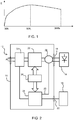
- the typical efficiency is as shown in Figure 1 , which plots the efficiency (E, y-axis) versus the loading as a percentage of the rated load. There is a particular efficiency issue at low load conditions.
- auxiliary driver to deliver power to a LED lighting load, instead of a main LED driver, when the LED power demand is sufficiently low that it can be met by the auxiliary driver.
- the auxiliary driver is generally a low power driver and is originally only intended for auxiliary modules, such as sensors and communications circuits, and has a power delivery capability which is lower than the peak power demand of the LED lighting load.
- a driver arrangement for a LED lighting device with a LED light source and at least one additional auxiliary module comprising:
- the controller for example controls the delivery of power from the auxiliary driver to the auxiliary power output or to both the main power output and the auxiliary power output.
- This driver arrangement has separate drivers for an LED lighting device and for one or more auxiliary modules. In this way, each driver can be optimized for the load it is required to drive. This means that the device may be more efficient in a low power lighting mode, by using a driver suited for such low power operation.
- the output of the auxiliary driver is able to be used to power the LED light source. This may for example be appropriate when the power demand of the LED light source is low, for example during periods of deep dimming. By using the auxiliary driver for this time, the overall efficiency of the driver arrangement may be improved.
- the controller is for example adapted to control the auxiliary driver to provide power to the LED light source when the output power of the LED light source is set lower than a threshold value.
- This threshold relates to the power capability of the auxiliary driver.
- the auxiliary driver may be used to deliver the required power more efficiently that the main LED driver.
- the controller may comprise a power control loop comprising a sensor for sensing a power delivery to the LED light source from the auxiliary driver and to control a power delivery to the LED light source from the main driver accordingly.
- the power control loop is for the main LED driver and comprises a sensor for sensing a power delivery to the LED light source from the auxiliary driver or from both of the main LED driver and the auxiliary driver.
- the power control loop is adapted to control a power delivery to the LED light source from the main power conversion circuit such that the power delivery to the LED light source matches an output power demand of the LED light source.
- the controller is preferably adapted to control the delivery of power in dependence on the power demand of the LED light source and of the at least one additional auxiliary module.
- auxiliary driver either for the auxiliary module (or modules) or additionally for the LED light source thus takes account of both power demands. If both can be met by the auxiliary driver, then it will be used as the sole power supply. If both cannot be met by the auxiliary driver, then the auxiliary driver should not be overloaded and preferably the two drivers will both be used.
- the controller is for example adapted to retrieve the power demand of the at least one additional auxiliary module by:
- the controller may be adapted to set the power output of the auxiliary driver to be the smaller of:
- the output power of the auxiliary driver is set to a sum of the power demand of the at least one additional auxiliary module and the output power demand of the LED light source. If this sum exceeds the peak power output capability of the auxiliary driver, then it is set to the peak power. This means that the auxiliary driver alone is used whenever possible. Whenever the total power demand cannot be met only by the auxiliary driver, then the auxiliary driver is driven to its full power, and the surplus additional power requirement is delivered by the main LED driver. This means the efficiency is improved, because the auxiliary driver is always responsible for the lowest tranche of power demand.
- the auxiliary driver for example comprises a constant voltage driver for the additional modules.
- the additional modules for example then comprise input/output power control capability so that they can function properly from a constant voltage power supply.
- the controller is adapted to maintain a peak current corresponding to the peak output power of the auxiliary driver, meanwhile regulating the voltage on the auxiliary power output.
- the controller is adapted to maintain a current corresponding to the output power demand of the LED light source meanwhile regulating the voltage on the auxiliary power output.
- This preferred embodiment defines the feedback control loop for the auxiliary driver.
- the auxiliary driver may comprise a main power inductor and a first secondary inductor magnetically coupled to the main power inductor and adapted to connect to the at least one additional auxiliary module. This provides an isolated supply to the auxiliary module. Further, there may be a second secondary inductor for providing a second isolated supply to a different type of auxiliary module.
- the two secondary inductors may give rise to different transformer ratios so that the outputs voltage can be different and are adapted to the different types of auxiliary loads to be supplied, such as 5V loads and 12V loads etc..
- the main power inductor is for example adapted to connect to the LED light source, in an electrically direct manner.
- the auxiliary driver comprises a further secondary inductor magnetically coupled to the main power inductor and adapted to connect to the LED light source. This means that both supplies are isolated.
- the invention also provides a lighting device comprising:
- This provides a lighting device which incorporates the driver arrangement described above.
- the at least one additional auxiliary module may comprise:
- auxiliary modules There may be a single module or multiple modules. They are used to form a network of devices. Typically, the modules add functionality to the light system, such as based on presence detection, ambient light sensing etc. However, the modules may be provided for other purposes, for example as part of an intruder detection system, or sensors for controlling a heating, ventilation and air conditioning system (HVAC).
- HVAC heating, ventilation and air conditioning system
- the invention also provides a method of controlling the supply of power from a driver arrangement to a LED lighting device with a LED light source and to at least one additional auxiliary module, the method comprising:
- the selective control of power delivery enables efficiency improvements to be obtained, by avoiding operating a high power driver at very low power demand levels.
- the method may comprise controlling the auxiliary driver to provide power to the LED light source when the output power of the LED light source is set lower than a threshold value.
- a power delivery to the LED light source from the auxiliary driver may be sensed so that a power delivery to the LED light source is then controlled from the main LED driver accordingly.
- Selectively controlling the delivery of power is for example in dependence on the power demand of the LED light source and of the at least one additional auxiliary module.
- the method may comprise setting the power output of the auxiliary driver to be the smaller of:
- the auxiliary driver is used preferentially for low power demands.
- the invention provides a driver arrangement for a LED lighting device, in which the lighting device has a LED light source and at least one additional auxiliary module.
- the driver arrangement comprises separate main and auxiliary drivers.
- the delivery of power from the auxiliary driver is controlled to either an auxiliary power output or to both a main power output and the auxiliary power output.
- Each driver can be optimized for the load it is required to drive.
- the device may overall be more efficient in a low power mode, by using a driver suited for such low power operation.
- the auxiliary driver may be used.
- Figure 2 shows a driver arrangement 10 for a LED lighting device 12 with a LED light source 14 and at least one additional auxiliary module 16.
- the lighting device is defined as the overall system, including the light source, the driver arrangement and the auxiliary modules.
- the driver arrangement 10 has a main power output 18 for providing power to the LED light source 14.
- a main LED driver 20 is connected to the main power output 18. It comprises a switch mode power supply, having a main power conversion circuit. Alternatively the main LED driver could also be a linear power supply or other type of power supply instead of the switch mode power supply.
- An auxiliary power output 22 is provided for providing power to the at least one additional auxiliary module 16.
- An auxiliary driver 24 is connected to the auxiliary power output 22.
- the auxiliary driver 24 also comprises a switch mode power supply, having an auxiliary power conversion circuit independent from the main LED driver 20. Alternatively the auxiliary driver 24 could also be other types of power supply.
- the main LED driver and the auxiliary driver 24 usually are connected in parallel and both to the input like AC or DC grid.
- a controller 26 is used to control the two drivers.
- the power from the auxiliary driver may be controlled to be provided only to the auxiliary power output or to both the main power output and the auxiliary power output.
- the ratio of power from the auxiliary driver to the LED and the additional modules is adjustable.
- the auxiliary driver 24 has an output 25 which is combined with the output of the main driver at combiner 26 before delivery to the LED light source 14.
- This driver arrangement has separate drivers for the LED lighting source and for auxiliary modules. In this way, each driver can be optimized for the load it is required to drive. This means that the device may be more efficient in a low power lighting mode, by using a driver suited for such low power operation.
- the auxiliary driver is for example used to power the LED light source when the power demand of the LED light source is low, for example during periods of deep dimming. By using the auxiliary driver for this time, the overall efficiency of the driver arrangement may be improved.
- the auxiliary power supply is thus used to replace the low-efficiency main LED driver during light load conditions thereby to achieve more efficient LED driver operation over the full load range.
- the main LED driver 20 may be designed to operate at a maximum load of 100W whereas the auxiliary driver may be designed to operate with a maximum load of 10W. More generally, the peak power delivery of the main driver is more than 3 times, preferably more than 5 times, and preferably more than 8 times the peak power delivery of the auxiliary driver.
- the auxiliary power supply can then be used to supply the LED light source. This results in a more efficient operation than if the main LED driver is used.
- the load of the auxiliary power supply is typically variable over time (sensors are for example activated periodically or communications are intermittent) so the auxiliary driver is not always operated at a full load condition, and part of the load capacity is often available for use in supplying the LED light source.
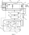
- FIG. 3 shows one example of the circuit in more detail.
- the main driver 20 has a main power conversion circuit 32 and a rectifier 33.
- the main power conversion circuit is a switch mode power converter, which is shown as a buck converter in this example.
- a current sense resistor 15 enables sensing of the LED current, for example for providing feedback control.
- the controller 26 is shown as two separate control units, one 26a for the main driver power supply and one 26b for the auxiliary driver power supply.
- the auxiliary driver 24 has an auxiliary power conversion circuit 34. It also comprises a buck-boost converter architecture with a main inductor 42. The auxiliary power conversion circuit is supplied by the rectified signal from the main converter rectifier 33, and it generates an output suitable for the LED light source 14.
- the auxiliary driver 24 shown has a dual switch topology, with two switching transistors Q1 and Q2 controlled with same driver signal sequence and two diodes D1 and D2.
- the output is switchable to the LED light source 14 by controlling the output voltage.
- the output of the auxiliary driver 24 is provided to the LED light source 14 through an output diode 50.
- an output current from the auxiliary driver can be prevented from reaching the LED light source if the output voltage is kept below the LED string voltage.
- the current provided is sensed by sensor 52 and this sensing information is provided to the controller 26b.
- the node 53 shown in Figure 3 may be considered to correspond to the combiner 26 of Figure 2 .
- the auxiliary driver further has a flyback topology for supplying the additional modules, and has a first secondary side power output circuit having a first secondary side inductor 44, and a second secondary side power output circuit having a second secondary side inductor 46.
- Those two first secondary side inductors are magnetically coupled to the main inductor 42 in a flyback manner so as to freewheel power when the switches Q1 and Q2 are off.
- These two power output circuits provide different output power supplies for different types of auxiliary circuit 16.
- FIG 4 shows the auxiliary driver 24 in more detail.
- a first current sense resistor Rpk is provided for measuring the peak primary side current Ipk in the boost charging phase
- a second current sense resistor Rs' is provided for measuring the output current to the LED light source.
- the second current sense resistor can be represented schematically in Figure 3 as the sensor 52.
- both switches Q1 and Q2 are on, the power is accumulated in the main inductor 42; in the freewheeling phase, the main inductor 42 discharges to the buffer capacitor C B , in turn to the LEDs, via the diode D2, and also the secondary inductor 44 discharges via the diode D3 and to the additional modules.
- the power supply for the auxiliary modules is for example a fixed voltage Vo
- the auxiliary load 16 for example comprises a low drop out regulator or switch mode power supply 16a followed by a master control unit or sensor 16b.
- the consumed power Po depends on the power consumption of the controller or sensor and the preceding converter/regulator.
- the parameters of current in the charging phase, the current though to the LEDs, and the voltage Vo may be used in the feedback control loop of the auxiliary driver, which will be described later.
- FIG. 5 shows one example of the control method implemented by the controllers 26a, 26b.
- step 60 the power demand of the LED light source is obtained.
- This in particular relates to the dimming setting.
- This dimming setting is for example communicated to the controller 26a over a wireless connection (and the wireless communications circuitry is one of the auxiliary modules, powered by the auxiliary driver).
- step 62 it is determined if the LED load is greater than 10W (for the example of a 100W main driver and 10W auxiliary driver). Thus, the current setting is at a level higher than 10% of the maximum. If the LED load demand is greater than 10W, then the main driver is used to supply the LED load in step 64.
- the main driver and the auxiliary driver operate separately. This can be achieved by tuning the output of the auxiliary driver to be slightly lower than the LED string voltage drop, so that the auxiliary driver will not provide power to LED load.
- step 66 it is determined if the total load demand, namely the LED load demand and the power demand of the auxiliary modules, is greater than 10W.
- the controller 26a For determining the LED load demand, the controller 26a is aware of it since the dimming level is already known.
- the auxiliary load demand can be obtained by detecting the primary winding current and current sense resistor voltage for the sense resistor Rpk, in particular when no power is being delivered to the LED load.
- the controller can request the additional modules to inform its power demand.
- Ipk is the peak primary side current
- fs is the switching frequency
- Lk is the inductance
- the auxiliary power is thus given by subtracting the load contribution of the LED light source as provided by the auxiliary driver:
- P auxiliary load 1 / 2 Lk * Ipk * Ipk * fs ⁇ Vled * V Rs ′ / Rs ′
- the auxiliary load information can be directly given by the auxiliary load itself which include a microcontroller.
- the controller 26b can then make a judgement of whether the needed LED driver load and auxiliary load is larger than the set threshold (10W in this example).
- the auxiliary driver operates at full rated power (i.e. it operates at 10W).
- This 10W comprises the auxiliary power (e.g. the power P SB ) and the balance (10-P SB ) is provided by the auxiliary driver to the LED light source. The remaining power is delivered by the main driver. This is step 68.
- the additional module can regulate its input power as P SB , so that the remaining power (10-P SB ) is automatically supplied to LED light source by setting the output voltage slightly higher than the LED string voltage.
- the main driver and the auxiliary driver then supply the LED load in parallel.
- the sensing resistor Rs is placed before the current return path (ground) to the auxiliary driver, the total LED current from both the main LED driver and the auxiliary driver is sensed by current sensing resistor Rs.
- the closed loop control then maintains the main LED driver at a setting to provide the required additional current output.
- the main driver will provide power corresponding to the dimming level power level minus (10-P SB ).
- the peak current of the primary winding is set to: ⁇ 10 * 2 / Lk / fs .
- step 70 If the total demand is not greater than 10W, then the main driver can be turned off and the auxiliary driver operates this total demand level, providing both the auxiliary power requirement and the LED load requirement. This is step 70.
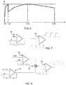
- Figure 6 shows the efficiency improvement achieved by adopting the architecture explained above.
- the low power operation shows improved efficiency, since the auxiliary driver is used by default for lower power operation.
- Figure 7 shows an example of a control scheme for controlling the main driver in response to the sensed voltage Vs across the current sense resistor Rs as long as it is involved, when the auxiliary driver does not provide power to the LED, or when the auxiliary driver provides power to the LED and the power is not enough (total power demand on the LED is more than the threshold (10W)).
- the voltage Vs is compared with a reference voltage Ref which corresponds to the desired dimming level.
- a first amplifier circuit 80 generates an output signal based on a comparison between Vs and VLED and this is compared with a sawtooth reference waveform in a comparator 82 thereby generating a PWM gate control signal for the main driver.
- Figure 8 shows an example of a control scheme for controlling the auxiliary driver in response to the sensed voltage Vspk across the sense resistor Rpk when the auxiliary driver is outputting its peak power such as 10W.
- the voltage Vspk on the sensing resistor Rpk is compared with a reference voltage VIpk which corresponds to the peak primary current in order to provide the peak (10W) output power.
- a first amplifier circuit 90 generates an output signal based on a comparison between VIpk and Vspk. This means if the real current at the charging phase is less than a peak charging current corresponding to 10W, the duty cycle of the driver will be increased to increase the real current.
- a second amplifier circuit 90 generates an output signal based on a comparison between the auxiliary driver output voltage Vo (shown in Figure 4 ) and a desired output voltage setting Vo_ref. This means if the real output voltage Vo is less than the voltage reference, the duty cycle of the driver will be increased to increase the real output voltage.
- a summing unit 94 performs a sum operation.
- the output of the unit 94 is provided to a comparator 96 whose other input is a saw tooth signal, thereby generating a PWM gate control signal for the auxiliary driver. More specifically, if the value Vo is much less than Vo_ref, or the real current is much less than the current corresponding to 10W operation, the amplifier circuit will output a high value to the comparator 96, the high value is compared with the saw tooth wave giving rise to a high duty cycle. The comparator thus outputs longer high state period, thereby to increase the on time of the switches Q1 and Q2 to increase power charging, thereby increasing the power of the driver in order to increase the value of Vo or the real current. An opposite function takes place when the value Vo is high or the current is high, leading to a low duty cycle and reduced on time of the switches Q1 and Q2.
- the main LED driver will be turned off and the auxiliary driver will provide the combined power.
- the auxiliary driver only needs to obtain the dimming command of LED driver and detect the additional module's load (or receive load information from a load controller), and it can adjust the on time of the auxiliary driver switch to make sure the total output power matches the needed LED power and auxiliary load based on closed loop control.
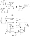
- Figure 9 shows a control scheme for use when the total power requirement is less than the threshold (10W).
- a further amplifier 100 is provided for generating the reference for the amplifier 90.
- the further amplifier 100 compares the voltage Vs across the main driver current sense resistor Rs which corresponds to the output current to the LED, with the reference voltage Ref which corresponds to a current matching the desired dimming level. This then generates the reference VIpk of the amplifier 90 to compare with the Vspk of the charging phase current, which reference VIpk is below the maximum power setting used as a static reference in Figure 8 .
- the feedback control loop also comprises a comparison of the output voltage Vo with a reference, and comparison with a saw tooth wave to generate the signal to control the duty cycle of the switches Q1 and Q2. Those two portions are similar to those in Figure 8 , and thus will not be described again.
- FIG. 10 shows an alternative implementation of the auxiliary driver circuit 24.
- the auxiliary modules are supplied by a power output circuit with a first secondary winding 44 and the LED lighting device is supplied by a further power output circuit with a further secondary winding 102. In this way, an isolated output is provided to the LED lighting device as well as to the auxiliary circuits.
- the auxiliary driver sensing signal Vs' (based on the current sense resistor Rs') can be transmitted to controller through signal isolators such as an opto-coupler 104 after signal processing in a signal processor 106.
- this sensing information enables auxiliary load information calculation.
- the controller 26b is powered by supply voltage Vcc generated by a primary side power supply circuit 108.
- the controller 26b receives the primary side peak current measurement as well as the LED current measurement based on the current through current sense resistor Rs'.
- the auxiliary modules may take various forms. Typically, they may comprise an RF communication device for receiving wireless control commands, or a sensor device such as for presence detection, ambient light sensing etc.
- 10W and 100W are of course just examples, and the peak lighting power and auxiliary module powers may take any suitable value.
- the 10% differences is also just an example - it may typically anywhere in the range 5% to 25%.
- the auxiliary driver has a peak power (e.g. 10W) sufficient to operate the auxiliary modules, and a standby power (e.g. 0.2W) sufficient to meet to the standby power requirements.
- a peak power e.g. 10W
- a standby power e.g. 0.2W
- driver architecture has been given for the main driver and the auxiliary driver.
- different power supply circuits may be used. Different switch mode power supply circuits may be used (buck, boost, buck-boost), or the power supply circuits may not be based on switch mode power supplies at all. In all cases, the (at least) two different drivers will have different efficiency performance, so that efficiency gains are possible by preferentially using one driver over the other for low power operation.
- a computer program may be stored/distributed on a suitable medium, such as an optical storage medium or a solid-state medium supplied together with or as part of other hardware, but may also be distributed in other forms, such as via the Internet or other wired or wireless telecommunication systems. Any reference signs in the claims should not be construed as limiting the scope.
Landscapes
- Circuit Arrangement For Electric Light Sources In General (AREA)
Abstract
A driver arrangement is provided for a LED lighting device with a LED light source and at least one additional auxiliary module. The driver arrangement comprises separate main and auxiliary drivers. The delivery of power from the auxiliary driver is controlled to either an auxiliary power output or to both a main power output and the auxiliary power output. Each driver can be optimized for the load it is required to drive. The device may overall be more efficient in a low power auxiliary mode, by using a driver suited for such low power operation. In particular when the power demand of the LED light source is low, the auxiliary driver may be used.
Description
- This invention relates to LED lighting systems and drivers, and relates in particular to lighting systems in which additional functionality is integrated into the luminaires of the lighting system, for example for sensing or communication purposes.
- In complex lighting systems, for example smart lighting systems in which luminaires include local sensors and/or communications modules, a power supply is needed which generates multiple outputs. An auxiliary supply is needed, in addition to the main supply for the lighting load, for supplying master control units, logic circuits, gate drivers sensors and/or communications modules etc.
- An issue with the provision of these additional functions is that the standby power consumption becomes an issue. There are regulatory standby power consumption requirements for lamps or stand-alone LED drivers below 500mW. For example, the California Energy Commission is pushing ahead with a requirement for a 0.2W maximum standby power for connected lamps.
- In order to achieve this low standby power consumption target, a standalone auxiliary power supply is widely adopted in an LED driver. There is then a standby power supply separate to the main LED driver, which functions as the power supply for the lighting load.
- A dimming function is a common feature provided by a LED driver. When the LED driver power is dimmed down, the efficiency is very important in order to provide energy savings. The LED driver must be designed according to the maximum power requirements, so large current rating components are used in the design which means the high -efficiency region is at the average to high power/load and the efficiency of LED driver at a light load is low. The typical efficiency is as shown in
Figure 1 , which plots the efficiency (E, y-axis) versus the loading as a percentage of the rated load. There is a particular efficiency issue at low load conditions. - There is therefore a need to enable improved efficiency in a driver for a LED light source and which enables additional modules to be provided with a low standby power requirement.
- The invention is defined by the claims.
- It is a concept of the invention to make use of an auxiliary driver to deliver power to a LED lighting load, instead of a main LED driver, when the LED power demand is sufficiently low that it can be met by the auxiliary driver. The auxiliary driver is generally a low power driver and is originally only intended for auxiliary modules, such as sensors and communications circuits, and has a power delivery capability which is lower than the peak power demand of the LED lighting load. By reusing the auxiliary driver for powering the LED, operation of the main LED driver at low power level is reduced or prevented, and low power efficiency is avoided.
- According to examples in accordance with an aspect of the invention, there is provided a driver arrangement for a LED lighting device with a LED light source and at least one additional auxiliary module, the driver arrangement comprising:
- a main power output for providing power to the LED light source;
- a main LED driver having a main power conversion circuit, the main LED driver connected to the main power output;
- an auxiliary power output for providing power to the at least one additional auxiliary module;
- an auxiliary driver, wherein the auxiliary driver has an auxiliary power conversion circuit independent from the main LED driver; and
- a controller for controlling the ratio of delivery of power from the auxiliary driver to the main power output and the auxiliary power output.
- The controller for example controls the delivery of power from the auxiliary driver to the auxiliary power output or to both the main power output and the auxiliary power output.
- This driver arrangement has separate drivers for an LED lighting device and for one or more auxiliary modules. In this way, each driver can be optimized for the load it is required to drive. This means that the device may be more efficient in a low power lighting mode, by using a driver suited for such low power operation. In addition to providing at least two independent drivers, the output of the auxiliary driver is able to be used to power the LED light source. This may for example be appropriate when the power demand of the LED light source is low, for example during periods of deep dimming. By using the auxiliary driver for this time, the overall efficiency of the driver arrangement may be improved.
- The controller is for example adapted to control the auxiliary driver to provide power to the LED light source when the output power of the LED light source is set lower than a threshold value. This threshold relates to the power capability of the auxiliary driver.
- Thus, when the LED light source power demand is low, the auxiliary driver may be used to deliver the required power more efficiently that the main LED driver.
- The controller may comprise a power control loop comprising a sensor for sensing a power delivery to the LED light source from the auxiliary driver and to control a power delivery to the LED light source from the main driver accordingly. The power control loop is for the main LED driver and comprises a sensor for sensing a power delivery to the LED light source from the auxiliary driver or from both of the main LED driver and the auxiliary driver. The power control loop is adapted to control a power delivery to the LED light source from the main power conversion circuit such that the power delivery to the LED light source matches an output power demand of the LED light source.
- In this way, it is ensured that the total power delivery to the LED light source is correct, by monitoring the contribution from the auxiliary supply and controlling the main driver accordingly.
- The controller is preferably adapted to control the delivery of power in dependence on the power demand of the LED light source and of the at least one additional auxiliary module.
- The decision of whether to use the output power of the auxiliary driver either for the auxiliary module (or modules) or additionally for the LED light source thus takes account of both power demands. If both can be met by the auxiliary driver, then it will be used as the sole power supply. If both cannot be met by the auxiliary driver, then the auxiliary driver should not be overloaded and preferably the two drivers will both be used.
- The controller is for example adapted to retrieve the power demand of the at least one additional auxiliary module by:
- receiving signaling from the at least one additional auxiliary module; or
- detecting the output power of the auxiliary driver when it does not output power to the LED light source.
- There are thus various ways to provide detection which allows the correct total power to be delivered to the LED light source and to the auxiliary modules.
- The controller may be adapted to set the power output of the auxiliary driver to be the smaller of:
- the peak output power of the auxiliary driver; and
- a sum of the power demand of the at least one additional auxiliary module an output power demand of the LED light source.
- In this way, the output power of the auxiliary driver is set to a sum of the power demand of the at least one additional auxiliary module and the output power demand of the LED light source. If this sum exceeds the peak power output capability of the auxiliary driver, then it is set to the peak power. This means that the auxiliary driver alone is used whenever possible. Whenever the total power demand cannot be met only by the auxiliary driver, then the auxiliary driver is driven to its full power, and the surplus additional power requirement is delivered by the main LED driver. This means the efficiency is improved, because the auxiliary driver is always responsible for the lowest tranche of power demand.
- The auxiliary driver for example comprises a constant voltage driver for the additional modules. The additional modules for example then comprise input/output power control capability so that they can function properly from a constant voltage power supply.
- Preferably, when the sum is higher than the peak output power, namely the auxiliary driver needs to work at its peak output power, the controller is adapted to maintain a peak current corresponding to the peak output power of the auxiliary driver, meanwhile regulating the voltage on the auxiliary power output.
- When the sum is lower than the peak output power, namely the auxiliary driver does not work at its peak output power, the controller is adapted to maintain a current corresponding to the output power demand of the LED light source meanwhile regulating the voltage on the auxiliary power output.
- This preferred embodiment defines the feedback control loop for the auxiliary driver.
- The auxiliary driver may comprise a main power inductor and a first secondary inductor magnetically coupled to the main power inductor and adapted to connect to the at least one additional auxiliary module. This provides an isolated supply to the auxiliary module. Further, there may be a second secondary inductor for providing a second isolated supply to a different type of auxiliary module. The two secondary inductors may give rise to different transformer ratios so that the outputs voltage can be different and are adapted to the different types of auxiliary loads to be supplied, such as 5V loads and 12V loads etc..
- The main power inductor is for example adapted to connect to the LED light source, in an electrically direct manner. Alternatively, the auxiliary driver comprises a further secondary inductor magnetically coupled to the main power inductor and adapted to connect to the LED light source. This means that both supplies are isolated.
- The invention also provides a lighting device comprising:
- a LED light source;
- at least one additional auxiliary module; and
- a driver arrangement as defined above.
- This provides a lighting device which incorporates the driver arrangement described above.
- The at least one additional auxiliary module may comprise:
- an RF communication device; or
- a sensor device.
- Different possible auxiliary modules are possible. There may be a single module or multiple modules. They are used to form a network of devices. Typically, the modules add functionality to the light system, such as based on presence detection, ambient light sensing etc. However, the modules may be provided for other purposes, for example as part of an intruder detection system, or sensors for controlling a heating, ventilation and air conditioning system (HVAC).
- The invention also provides a method of controlling the supply of power from a driver arrangement to a LED lighting device with a LED light source and to at least one additional auxiliary module, the method comprising:
- providing power to the LED light source (14) using a main LED driver having a main power conversion circuit;
- providing power to the at least one additional auxiliary module (16) using an auxiliary driver, wherein the auxiliary driver has an auxiliary power conversion circuit independent from the main LED driver; and
- selectively controlling the delivery of power from the auxiliary driver to only the at least one additional auxiliary module or to both the at least one additional auxiliary module and the LED light source.
- The selective control of power delivery enables efficiency improvements to be obtained, by avoiding operating a high power driver at very low power demand levels.
- The method may comprise controlling the auxiliary driver to provide power to the LED light source when the output power of the LED light source is set lower than a threshold value. A power delivery to the LED light source from the auxiliary driver may be sensed so that a power delivery to the LED light source is then controlled from the main LED driver accordingly. Selectively controlling the delivery of power is for example in dependence on the power demand of the LED light source and of the at least one additional auxiliary module.
- By way of example, the method may comprise setting the power output of the auxiliary driver to be the smaller of:
- the peak output power of the auxiliary driver; and
- a sum of the power demand of the at least one additional auxiliary module an output power demand of the LED light source.
- Thus, the auxiliary driver is used preferentially for low power demands.
- These and other aspects of the invention will be apparent from and elucidated with reference to the embodiment(s) described hereinafter.
- For a better understanding of the invention, and to show more clearly how it may be carried into effect, reference will now be made, by way of example only, to the accompanying drawings, in which:
-
Fig. 1 shows the typical energy efficiency of a LED driver at different load conditions; -
Fig. 2 shows a driver arrangement for a LED lighting device in accordance with an example of the invention; -
Fig. 3 shows one example of the circuit ofFig. 2 in more detail; -
Fig. 4 shows the auxiliary driver in more detail; -
Fig. 5 shows one example of the control method implemented by the controller; -
Fig. 6 shows the efficiency improvement achieved by adopting the architecture explained above; -
Fig. 7 shows an example of a control scheme for controlling the main driver; -
Fig. 8 shows an example of a control scheme for controlling the auxiliary driver; -
Fig. 9 shows a control scheme for use when the total power requirement is less than a threshold; and -
Fig. 10 shows an alternative implementation of the auxiliary driver circuit. - The invention will be described with reference to the Figures.
- It should be understood that the detailed description and specific examples, while indicating exemplary embodiments of the apparatus, systems and methods, are intended for purposes of illustration only and are not intended to limit the scope of the invention. These and other features, aspects, and advantages of the apparatus, systems and methods of the present invention will become better understood from the following description, appended claims, and accompanying drawings. It should be understood that the Figures are merely schematic and are not drawn to scale. It should also be understood that the same reference numerals are used throughout the Figures to indicate the same or similar parts.
- The invention provides a driver arrangement for a LED lighting device, in which the lighting device has a LED light source and at least one additional auxiliary module. The driver arrangement comprises separate main and auxiliary drivers. The delivery of power from the auxiliary driver is controlled to either an auxiliary power output or to both a main power output and the auxiliary power output. Each driver can be optimized for the load it is required to drive. The device may overall be more efficient in a low power mode, by using a driver suited for such low power operation. In particular, when the power demand of the LED light source is low, the auxiliary driver may be used.
-
Figure 2 shows adriver arrangement 10 for aLED lighting device 12 with aLED light source 14 and at least one additionalauxiliary module 16. InFigure 2 , the lighting device is defined as the overall system, including the light source, the driver arrangement and the auxiliary modules. - The
driver arrangement 10 has amain power output 18 for providing power to theLED light source 14. Amain LED driver 20 is connected to themain power output 18. It comprises a switch mode power supply, having a main power conversion circuit. Alternatively the main LED driver could also be a linear power supply or other type of power supply instead of the switch mode power supply. Anauxiliary power output 22 is provided for providing power to the at least one additionalauxiliary module 16. Anauxiliary driver 24 is connected to theauxiliary power output 22. Theauxiliary driver 24 also comprises a switch mode power supply, having an auxiliary power conversion circuit independent from themain LED driver 20. Alternatively theauxiliary driver 24 could also be other types of power supply. The main LED driver and theauxiliary driver 24 usually are connected in parallel and both to the input like AC or DC grid. - A
controller 26 is used to control the two drivers. In particular, the power from the auxiliary driver may be controlled to be provided only to the auxiliary power output or to both the main power output and the auxiliary power output. Namely the ratio of power from the auxiliary driver to the LED and the additional modules is adjustable. For this purpose, theauxiliary driver 24 has anoutput 25 which is combined with the output of the main driver atcombiner 26 before delivery to theLED light source 14. - This driver arrangement has separate drivers for the LED lighting source and for auxiliary modules. In this way, each driver can be optimized for the load it is required to drive. This means that the device may be more efficient in a low power lighting mode, by using a driver suited for such low power operation. The auxiliary driver is for example used to power the LED light source when the power demand of the LED light source is low, for example during periods of deep dimming. By using the auxiliary driver for this time, the overall efficiency of the driver arrangement may be improved.
- The auxiliary power supply is thus used to replace the low-efficiency main LED driver during light load conditions thereby to achieve more efficient LED driver operation over the full load range.
- By way of example, the
main LED driver 20 may be designed to operate at a maximum load of 100W whereas the auxiliary driver may be designed to operate with a maximum load of 10W. More generally, the peak power delivery of the main driver is more than 3 times, preferably more than 5 times, and preferably more than 8 times the peak power delivery of the auxiliary driver. - For the example of 100W and 10W, when the LED driver is instructed to dim down to below a 10% load level, and hence below 10W, the auxiliary power supply can then be used to supply the LED light source. This results in a more efficient operation than if the main LED driver is used. The load of the auxiliary power supply is typically variable over time (sensors are for example activated periodically or communications are intermittent) so the auxiliary driver is not always operated at a full load condition, and part of the load capacity is often available for use in supplying the LED light source.
-
Figure 3 shows one example of the circuit in more detail. - The
main driver 20 has a mainpower conversion circuit 32 and arectifier 33. The main power conversion circuit is a switch mode power converter, which is shown as a buck converter in this example. Acurrent sense resistor 15 enables sensing of the LED current, for example for providing feedback control. - The
controller 26 is shown as two separate control units, one 26a for the main driver power supply and one 26b for the auxiliary driver power supply. - The
auxiliary driver 24 has an auxiliary power conversion circuit 34. It also comprises a buck-boost converter architecture with amain inductor 42. The auxiliary power conversion circuit is supplied by the rectified signal from themain converter rectifier 33, and it generates an output suitable for theLED light source 14. - The
auxiliary driver 24 shown has a dual switch topology, with two switching transistors Q1 and Q2 controlled with same driver signal sequence and two diodes D1 and D2. The output is switchable to theLED light source 14 by controlling the output voltage. - The output of the
auxiliary driver 24 is provided to theLED light source 14 through anoutput diode 50. Thus, an output current from the auxiliary driver can be prevented from reaching the LED light source if the output voltage is kept below the LED string voltage. The current provided is sensed bysensor 52 and this sensing information is provided to thecontroller 26b. Thenode 53 shown inFigure 3 may be considered to correspond to thecombiner 26 ofFigure 2 . - The auxiliary driver further has a flyback topology for supplying the additional modules, and has a first secondary side power output circuit having a first
secondary side inductor 44, and a second secondary side power output circuit having a secondsecondary side inductor 46. Those two first secondary side inductors are magnetically coupled to themain inductor 42 in a flyback manner so as to freewheel power when the switches Q1 and Q2 are off. These two power output circuits provide different output power supplies for different types ofauxiliary circuit 16. -
Figure 4 shows theauxiliary driver 24 in more detail. A first current sense resistor Rpk is provided for measuring the peak primary side current Ipk in the boost charging phase, and a second current sense resistor Rs' is provided for measuring the output current to the LED light source. The second current sense resistor can be represented schematically inFigure 3 as thesensor 52. In the boost charging phase, both switches Q1 and Q2 are on, the power is accumulated in themain inductor 42; in the freewheeling phase, themain inductor 42 discharges to the buffer capacitor CB, in turn to the LEDs, via the diode D2, and also thesecondary inductor 44 discharges via the diode D3 and to the additional modules. - The power supply for the auxiliary modules is for example a fixed voltage Vo, and the
auxiliary load 16 for example comprises a low drop out regulator or switchmode power supply 16a followed by a master control unit orsensor 16b. The consumed power Po depends on the power consumption of the controller or sensor and the preceding converter/regulator. - The parameters of current in the charging phase, the current though to the LEDs, and the voltage Vo may be used in the feedback control loop of the auxiliary driver, which will be described later.
-
Figure 5 shows one example of the control method implemented by thecontrollers - In
step 60, the power demand of the LED light source is obtained. This in particular relates to the dimming setting. This dimming setting is for example communicated to thecontroller 26a over a wireless connection (and the wireless communications circuitry is one of the auxiliary modules, powered by the auxiliary driver). - In
step 62, it is determined if the LED load is greater than 10W (for the example of a 100W main driver and 10W auxiliary driver). Thus, the current setting is at a level higher than 10% of the maximum. If the LED load demand is greater than 10W, then the main driver is used to supply the LED load instep 64. The main driver and the auxiliary driver operate separately. This can be achieved by tuning the output of the auxiliary driver to be slightly lower than the LED string voltage drop, so that the auxiliary driver will not provide power to LED load. - If the LED load demand is not greater than 10W, then in
step 66, it is determined if the total load demand, namely the LED load demand and the power demand of the auxiliary modules, is greater than 10W. - For determining the LED load demand, the
controller 26a is aware of it since the dimming level is already known. - The auxiliary load demand can be obtained by detecting the primary winding current and current sense resistor voltage for the sense resistor Rpk, in particular when no power is being delivered to the LED load. Alternatively the controller can request the additional modules to inform its power demand.
- For a flyback converter topology, the input power is given by:

- This applies under discontinuous current mode (DCM). Ipk is the peak primary side current, fs is the switching frequency and Lk is the inductance. By selecting a fixed frequency flyback controller and using the design to make sure the circuit operates under DCM, the value Ipk represents the total auxiliary power.
- The auxiliary power is thus given by subtracting the load contribution of the LED light source as provided by the auxiliary driver:

- Alternatively, the auxiliary load information can be directly given by the auxiliary load itself which include a microcontroller. The
controller 26b can then make a judgement of whether the needed LED driver load and auxiliary load is larger than the set threshold (10W in this example). - If the total demand is greater than 10W, then the auxiliary driver operates at full rated power (i.e. it operates at 10W). This 10W comprises the auxiliary power (e.g. the power PSB) and the balance (10-PSB) is provided by the auxiliary driver to the LED light source. The remaining power is delivered by the main driver. This is
step 68. - By setting the peak current Ipk of the primary winding in the auxiliary driver, the total output power is fixed, and also the additional module can regulate its input power as PSB, so that the remaining power (10-PSB) is automatically supplied to LED light source by setting the output voltage slightly higher than the LED string voltage. The main driver and the auxiliary driver then supply the LED load in parallel. In the main driver, due to the fact that the sensing resistor Rs is placed before the current return path (ground) to the auxiliary driver, the total LED current from both the main LED driver and the auxiliary driver is sensed by current sensing resistor Rs. The closed loop control then maintains the main LED driver at a setting to provide the required additional current output. The main driver will provide power corresponding to the dimming level power level minus (10-PSB).
- When the auxiliary driver is operated at full load condition, the peak current of the primary winding is set to:

- If the total demand is not greater than 10W, then the main driver can be turned off and the auxiliary driver operates this total demand level, providing both the auxiliary power requirement and the LED load requirement. This is
step 70. -
Figure 6 shows the efficiency improvement achieved by adopting the architecture explained above. The low power operation shows improved efficiency, since the auxiliary driver is used by default for lower power operation. -
Figure 7 shows an example of a control scheme for controlling the main driver in response to the sensed voltage Vs across the current sense resistor Rs as long as it is involved, when the auxiliary driver does not provide power to the LED, or when the auxiliary driver provides power to the LED and the power is not enough (total power demand on the LED is more than the threshold (10W)). The voltage Vs is compared with a reference voltage Ref which corresponds to the desired dimming level. Afirst amplifier circuit 80 generates an output signal based on a comparison between Vs and VLED and this is compared with a sawtooth reference waveform in acomparator 82 thereby generating a PWM gate control signal for the main driver. -
Figure 8 shows an example of a control scheme for controlling the auxiliary driver in response to the sensed voltage Vspk across the sense resistor Rpk when the auxiliary driver is outputting its peak power such as 10W. - The voltage Vspk on the sensing resistor Rpk is compared with a reference voltage VIpk which corresponds to the peak primary current in order to provide the peak (10W) output power. A
first amplifier circuit 90 generates an output signal based on a comparison between VIpk and Vspk. This means if the real current at the charging phase is less than a peak charging current corresponding to 10W, the duty cycle of the driver will be increased to increase the real current. - A
second amplifier circuit 90 generates an output signal based on a comparison between the auxiliary driver output voltage Vo (shown inFigure 4 ) and a desired output voltage setting Vo_ref. This means if the real output voltage Vo is less than the voltage reference, the duty cycle of the driver will be increased to increase the real output voltage. A summingunit 94 performs a sum operation. - The output of the
unit 94 is provided to acomparator 96 whose other input is a saw tooth signal, thereby generating a PWM gate control signal for the auxiliary driver. More specifically, if the value Vo is much less than Vo_ref, or the real current is much less than the current corresponding to 10W operation, the amplifier circuit will output a high value to thecomparator 96, the high value is compared with the saw tooth wave giving rise to a high duty cycle. The comparator thus outputs longer high state period, thereby to increase the on time of the switches Q1 and Q2 to increase power charging, thereby increasing the power of the driver in order to increase the value of Vo or the real current. An opposite function takes place when the value Vo is high or the current is high, leading to a low duty cycle and reduced on time of the switches Q1 and Q2. - If the required LED driver load and auxiliary load is lower than 10W, the main LED driver will be turned off and the auxiliary driver will provide the combined power. The auxiliary driver only needs to obtain the dimming command of LED driver and detect the additional module's load (or receive load information from a load controller), and it can adjust the on time of the auxiliary driver switch to make sure the total output power matches the needed LED power and auxiliary load based on closed loop control.
-
Figure 9 shows a control scheme for use when the total power requirement is less than the threshold (10W). Instead of theamplifier 90 having a reference corresponding to the maximum power setting, afurther amplifier 100 is provided for generating the reference for theamplifier 90. Thefurther amplifier 100 compares the voltage Vs across the main driver current sense resistor Rs which corresponds to the output current to the LED, with the reference voltage Ref which corresponds to a current matching the desired dimming level. This then generates the reference VIpk of theamplifier 90 to compare with the Vspk of the charging phase current, which reference VIpk is below the maximum power setting used as a static reference inFigure 8 . The feedback control loop also comprises a comparison of the output voltage Vo with a reference, and comparison with a saw tooth wave to generate the signal to control the duty cycle of the switches Q1 and Q2. Those two portions are similar to those inFigure 8 , and thus will not be described again. -
Figure 10 shows an alternative implementation of theauxiliary driver circuit 24. The auxiliary modules are supplied by a power output circuit with a first secondary winding 44 and the LED lighting device is supplied by a further power output circuit with a further secondary winding 102. In this way, an isolated output is provided to the LED lighting device as well as to the auxiliary circuits. - For this type of isolated application, the auxiliary driver sensing signal Vs' (based on the current sense resistor Rs') can be transmitted to controller through signal isolators such as an opto-
coupler 104 after signal processing in asignal processor 106. As in the examples above, this sensing information enables auxiliary load information calculation. - The
controller 26b is powered by supply voltage Vcc generated by a primary sidepower supply circuit 108. - The
controller 26b receives the primary side peak current measurement as well as the LED current measurement based on the current through current sense resistor Rs'. - The auxiliary modules may take various forms. Typically, they may comprise an RF communication device for receiving wireless control commands, or a sensor device such as for presence detection, ambient light sensing etc.
- The example of 10W and 100W are of course just examples, and the peak lighting power and auxiliary module powers may take any suitable value. The 10% differences is also just an example - it may typically anywhere in the range 5% to 25%.
- The auxiliary driver has a peak power (e.g. 10W) sufficient to operate the auxiliary modules, and a standby power (e.g. 0.2W) sufficient to meet to the standby power requirements. When the auxiliary modules are in standby mode or even are operated, the difference (9.8W in this example) is able to be used for driving the LED load.
- Furthermore, only one example of driver architecture has been given for the main driver and the auxiliary driver. However different power supply circuits may be used. Different switch mode power supply circuits may be used (buck, boost, buck-boost), or the power supply circuits may not be based on switch mode power supplies at all. In all cases, the (at least) two different drivers will have different efficiency performance, so that efficiency gains are possible by preferentially using one driver over the other for low power operation.
- Variations to the disclosed embodiments can be understood and effected by those skilled in the art in practicing the claimed invention, from a study of the drawings, the disclosure and the appended claims. In the claims, the word "comprising" does not exclude other elements or steps, and the indefinite article "a" or "an" does not exclude a plurality. A single processor or other unit may fulfill the functions of several items recited in the claims. The mere fact that certain measures are recited in mutually different dependent claims does not indicate that a combination of these measures cannot be used to advantage. A computer program may be stored/distributed on a suitable medium, such as an optical storage medium or a solid-state medium supplied together with or as part of other hardware, but may also be distributed in other forms, such as via the Internet or other wired or wireless telecommunication systems. Any reference signs in the claims should not be construed as limiting the scope.
Claims (15)
- A driver arrangement (10) for a LED lighting device (12) with a LED light source (14) and at least one additional auxiliary module (16), the driver arrangement comprising:a main power output (18) for providing power to the LED light source (14);a main LED driver (20) having a main power conversion circuit (32), the main LED driver connected to the main power output (18);an auxiliary power output (22) for providing power to the at least one additional auxiliary module (16);an auxiliary driver (24), wherein the auxiliary driver has an auxiliary power conversion circuit (34) independent from the main LED driver; anda controller (26) for controlling the ratio of delivery of power from the auxiliary driver to the main power output and the auxiliary power output.
- A driver arrangement as claimed in claim 1, wherein the controller (26) is adapted to control the auxiliary driver (24) to provide power to the LED light source (14) when the output power of the LED light source is set lower than a threshold value.
- A driver arrangement as claimed in claim 1 or 2, wherein the controller (26) further comprises a power control loop (26a) for the main LED driver (20) which power control loop comprises:a sensor (52, 15) for sensing a power delivery to the LED light source from the auxiliary driver or from both of the main LED driver (20) and the auxiliary driver andthe power control loop is adapted to control a power delivery to the LED light source from the main power conversion circuit (32) accordingly such that the power delivery to the LED light source matches an output power demand of the LED light source.
- A driver arrangement as claimed in any one of claims 1 to 3, wherein the controller (26) is adapted to control the delivery of power in dependence on the power demand of the LED light source (14) and of the at least one additional auxiliary module (16).
- A driver arrangement as claimed in claim 4, wherein the controller (26) is adapted to retrieve the power demand of the at least one additional auxiliary module by:receiving signaling from the at least one additional auxiliary module; ordetecting the output power of the auxiliary driver when it does not output power to the LED light source.
- A driver arrangement as claimed in any one of claims 1 to 5, wherein the controller (26) is adapted to set the power output of the auxiliary driver (24) to be the smaller of:the peak output power of the auxiliary driver; anda sum of the power demand of the at least one additional auxiliary module and an output power demand of the LED light source.
- A driver arrangement as claimed in claim 6, wherein said controller is adapted to:maintain a peak current corresponding to the peak output power of the auxiliary driver, meanwhile regulating the voltage on the auxiliary power output (22), when the sum is higher than the peak output power; andmaintain a current corresponding to the output power demand of the LED light source meanwhile regulate the voltage on the auxiliary power output (22), when the sum lower higher than the peak output power.
- A driver arrangement as claimed in any one of claims 1 to 7, wherein the auxiliary driver (24) comprises a main power inductor (42) and a first secondary inductor (44) magnetically coupled to the main power inductor (42) and adapted to connect to the at least one additional auxiliary module (16).
- A driver arrangement as claimed in claim 8, wherein:the main power inductor (42) is adapted to connect to the LED light source (14) in a non-isolated manner; orthe auxiliary driver (24) comprises a second secondary inductor (102) magnetically coupled to the main power inductor (42) and adapted to connect to the LED light source (14).
- A LED lighting device comprising:a LED light source (14);at least one additional auxiliary module (16); anda driver arrangement (10) as claimed in any one of claims 1 to 9;wherein said at least one additional auxiliary module (16) is adapted to self-regulate the power from the auxiliary driver (24) at the auxiliary power output (22).
- A LED lighting device as claimed in claim 10, wherein the at least one additional auxiliary module (16) comprises:an RF communication device; ora sensor device.
- A method of controlling the supply of power from a driver arrangement (10) to a LED lighting device (12) with a LED light source (14) and to at least one additional auxiliary module (16), the method comprising:providing power to the LED light source (14) using a main LED driver (20) having a main power conversion circuit (32);providing power to the at least one additional auxiliary module (16) using an auxiliary driver (24), wherein the auxiliary driver has an auxiliary power conversion circuit (34) independent from the main LED driver; andselectively controlling the ratio of delivery of power from the auxiliary driver to the at least one additional auxiliary module (16) and the LED light source (14).
- A method as claimed in claim 12, comprising controlling the auxiliary driver (24) to provide power to the LED light source (14) when the output power of the LED light source is set lower than a threshold value.
- A method as claimed in claim 12 or 13, comprising sensing a power delivery to the LED light source from the auxiliary driver or from both of the auxiliary driver and the main LED driver and controlling a power delivery to the LED light source from the main LED driver (20) accordingly.
- A method as claimed in any one of claims 12 to 14, comprising selectively controlling the delivery of power in dependence on the power demand of the LED light source (14) and of the at least one additional auxiliary module (16), and comprising setting the power output of the auxiliary driver (24) to be the smaller of:the peak output power of the auxiliary driver; anda sum of the power demand of the at least one additional auxiliary module an output power demand of the LED light source.
Priority Applications (6)
| Application Number | Priority Date | Filing Date | Title |
|---|---|---|---|
| EP18181200.9A EP3592111A1 (en) | 2018-07-02 | 2018-07-02 | A driver arrangement for a led lighting device, a lighting device using the same and a drive method |
| EP19717332.1A EP3785491A1 (en) | 2018-04-23 | 2019-04-17 | A driver arrangement for a led lighting device, a lighting device using the same and a drive method |
| US17/047,633 US11457516B2 (en) | 2018-04-23 | 2019-04-17 | Driver arrangement for a LED lighting device, a lighting device using the same and a drive method |
| CN201980027869.6A CN112042278B (en) | 2018-04-23 | 2019-04-17 | Driver device for LED lighting apparatus, lighting apparatus using the same, and driving method |
| JP2020558919A JP7348205B2 (en) | 2018-04-23 | 2019-04-17 | Driver device for LED lighting device, lighting device using the driver device, and driving method |
| PCT/EP2019/059963 WO2019206771A1 (en) | 2018-04-23 | 2019-04-17 | A driver arrangement for a led lighting device, a lighting device using the same and a drive method |
Applications Claiming Priority (1)
| Application Number | Priority Date | Filing Date | Title |
|---|---|---|---|
| EP18181200.9A EP3592111A1 (en) | 2018-07-02 | 2018-07-02 | A driver arrangement for a led lighting device, a lighting device using the same and a drive method |
Publications (1)
| Publication Number | Publication Date |
|---|---|
| EP3592111A1 true EP3592111A1 (en) | 2020-01-08 |
Family
ID=62841992
Family Applications (1)
| Application Number | Title | Priority Date | Filing Date |
|---|---|---|---|
| EP18181200.9A Ceased EP3592111A1 (en) | 2018-04-23 | 2018-07-02 | A driver arrangement for a led lighting device, a lighting device using the same and a drive method |
Country Status (1)
| Country | Link |
|---|---|
| EP (1) | EP3592111A1 (en) |
Citations (3)
| Publication number | Priority date | Publication date | Assignee | Title |
|---|---|---|---|---|
| WO2015128388A1 (en) * | 2014-02-26 | 2015-09-03 | Koninklijke Philips N.V. | Driver arrangement |
| WO2015185570A1 (en) * | 2014-06-02 | 2015-12-10 | Eldolab Holding B.V. | Light unit driver system |
| US9826583B1 (en) * | 2015-12-17 | 2017-11-21 | Universal Lighting Technologies, Inc. | Auxiliary power supply with dynamically adjustable output |
-
2018
- 2018-07-02 EP EP18181200.9A patent/EP3592111A1/en not_active Ceased
Patent Citations (3)
| Publication number | Priority date | Publication date | Assignee | Title |
|---|---|---|---|---|
| WO2015128388A1 (en) * | 2014-02-26 | 2015-09-03 | Koninklijke Philips N.V. | Driver arrangement |
| WO2015185570A1 (en) * | 2014-06-02 | 2015-12-10 | Eldolab Holding B.V. | Light unit driver system |
| US9826583B1 (en) * | 2015-12-17 | 2017-11-21 | Universal Lighting Technologies, Inc. | Auxiliary power supply with dynamically adjustable output |
Similar Documents
| Publication | Publication Date | Title |
|---|---|---|
| US20220386432A1 (en) | Load Control Device for a Light-Emitting Diode Light Source | |
| US10485062B2 (en) | LED power-supply detection and control | |
| JP6430665B2 (en) | LED driver and driving method | |
| JP4199201B2 (en) | Power supply device and lighting device | |
| US8963425B2 (en) | Power supply device, lamp fitting, and vehicle | |
| RU2554080C2 (en) | Illumination device | |
| US9326351B2 (en) | LED controller comprising a clocked current source | |
| US20090184665A1 (en) | Drive Device for Leds and Related Method | |
| US10028340B2 (en) | Wall mounted AC to DC converter gang box | |
| EP2315497A1 (en) | An LED driver circuit having headroom/dropout voltage control and power factor correction | |
| US10141740B2 (en) | Auxiliary supply generation for power converters | |
| US10051704B2 (en) | LED dimmer circuit and method | |
| US10397998B2 (en) | Driver circuit and method | |
| US10271391B2 (en) | Light emitting diode driver | |
| US10397999B2 (en) | Lighting controller, a lighting system and a method for controlling lighting | |
| US11457516B2 (en) | Driver arrangement for a LED lighting device, a lighting device using the same and a drive method | |
| EP3592111A1 (en) | A driver arrangement for a led lighting device, a lighting device using the same and a drive method | |
| KR101472824B1 (en) | Power supply unit for led lighting fixtures | |
| US9326332B1 (en) | Ripple reduction in light emitting diode (LED)-based light bulb through increased ripple on an energy storage capacitor | |
| NL2033052B1 (en) | LED driver for controlling a LED fixture and a method of controlling a LED fixture | |
| JP2023127378A (en) | Lighting device and lighting fixture |
Legal Events
| Date | Code | Title | Description |
|---|---|---|---|
| PUAI | Public reference made under article 153(3) epc to a published international application that has entered the european phase |
Free format text: ORIGINAL CODE: 0009012 |
|
| AK | Designated contracting states |
Kind code of ref document: A1 Designated state(s): AL AT BE BG CH CY CZ DE DK EE ES FI FR GB GR HR HU IE IS IT LI LT LU LV MC MK MT NL NO PL PT RO RS SE SI SK SM TR |
|
| AX | Request for extension of the european patent |
Extension state: BA ME |
|
| STAA | Information on the status of an ep patent application or granted ep patent |
Free format text: STATUS: THE APPLICATION HAS BEEN REFUSED |
|
| 18R | Application refused |
Effective date: 20200201 |