EP3590837A1 - Lavatory with stowage equipment - Google Patents
Lavatory with stowage equipment Download PDFInfo
- Publication number
- EP3590837A1 EP3590837A1 EP19182716.1A EP19182716A EP3590837A1 EP 3590837 A1 EP3590837 A1 EP 3590837A1 EP 19182716 A EP19182716 A EP 19182716A EP 3590837 A1 EP3590837 A1 EP 3590837A1
- Authority
- EP
- European Patent Office
- Prior art keywords
- side wall
- lavatory
- stowage compartment
- space
- aircraft
- Prior art date
- Legal status (The legal status is an assumption and is not a legal conclusion. Google has not performed a legal analysis and makes no representation as to the accuracy of the status listed.)
- Ceased
Links
Images
Classifications
-
- B—PERFORMING OPERATIONS; TRANSPORTING
- B64—AIRCRAFT; AVIATION; COSMONAUTICS
- B64D—EQUIPMENT FOR FITTING IN OR TO AIRCRAFT; FLIGHT SUITS; PARACHUTES; ARRANGEMENTS OR MOUNTING OF POWER PLANTS OR PROPULSION TRANSMISSIONS IN AIRCRAFT
- B64D11/00—Passenger or crew accommodation; Flight-deck installations not otherwise provided for
- B64D11/02—Toilet fittings
-
- A—HUMAN NECESSITIES
- A47—FURNITURE; DOMESTIC ARTICLES OR APPLIANCES; COFFEE MILLS; SPICE MILLS; SUCTION CLEANERS IN GENERAL
- A47K—SANITARY EQUIPMENT NOT OTHERWISE PROVIDED FOR; TOILET ACCESSORIES
- A47K4/00—Combinations of baths, douches, sinks, wash-basins, closets, or urinals, not covered by a single other group of this subclass
Definitions
- the present invention relates generally to aircraft enclosures, and more particularly relates to an aircraft cabin lavatory and compartment formed in a wall therein.
- a lavatory In a commercial aircraft, a lavatory has a minimal footprint that is typically the width of a door, plus the area taken up by the sink and commode.
- a sink takes up a large portion of the space in a lavatory, as is necessary to capture a flow of water when washing of hands, etc.
- Above the sink is either a wall or a mirror, and a small drawer or cabinet may be provided for minimal supplies, tissue, soap, paper towels, and the like.
- the area below the sink of an aircraft lavatory serves as a storage compartment in the aircraft, which may store life vests, emergency supplies, or other aircraft items used by the flight attendants.
- the present invention takes advantage of the area behind the wall to create a new storage area accessible adjacent the door of the lavatory.
- the present invention is a stowage compartment built into the lavatory and accessible from the main cabin.
- the stowage compartment is formed between a newly installed wall in the lavatory that extends generally the length of the lavatory and from the ceiling to a height just above a low profile sink.
- the newly created space can include a pull out drawer or a small door that provides access to the stowage compartment.
- the present invention increases the storage area in the aircraft without reducing the area for passenger legroom or the galley, depending upon the location of the lavatory with respect to the rest of the cabin.
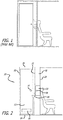
- Figure 1 illustrates a prior art version of an aircraft lavatory, juxtaposed with a passenger seat, such as might be found at the rear of a commercial aircraft.
- the lavatory includes a sink, with a recessed area above the sink to allow the passenger to wash their hands.
- the area below the sink is available for stowage, but there wall of the lavatory rests against the passenger seat, excluding any means by which further space could be utilized.
- the lavatory 10 includes a door 12 with a knob or handle 14 to gain ingress and egress into the lavatory 10, and a vent 16 at the lower portion of the door 12.
- the lavatory is formed by a first side wall 20 and a second side wall 22.
- a rear wall (not shown) cooperates with the floor 24 and ceiling 26 to form a standard lavatory compartment.
- an additional side wall 28 is located adjacent the second side wall 22, forming a volume between the additional side wall 28 and second side wall 22 below the ceiling.
- This newly created volume can be divided into two smaller volumes, a first volume forming an amenities area 30 for bathroom tissue, soap, paper towels, air sickness bags, and other items found in an aircraft bathroom.
- the remaining portion of the volume is used to create a stowage compartment 32, accessible from outside the lavatory 10 and preferably having locking means 34.
- the stowage compartment 32 can be accessed through a door, or it may be a drawer that slides into and out of the volume between the walls 22,28.
- a low profile sink 36 is shown in shadow illustrating its position within the lavatory. In this case, the sink 36 completely extends inwardly (relative to the compartment) from the plane of the wall 22, as compared with the prior art sink ( FIG.
- the sink is disposed behind the plane defined by the wall.
- the space is created to locate the stowage compartment 32.
- a commode would be positioned behind the door, but is omitted here for simplicity.
- the stowage compartment 32 does not need to be positioned directly over the sink, but this provides an efficient location for maximizing the space available between the walls.
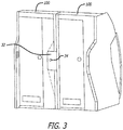
- United States Patent Publication No. 2011/0253835 illustrates an aircraft lavatory that is shaped to accommodate the seats or other structures that may be adjacent to the lavatory. As shown in Figure 3 , this type of lavatory can also be used in conjunction with the present invention.
- the adjacent walls create a space in between that can be used for the stowage compartment 32 of the present invention.
- one side wall of the lavatory on the right can serve as the outer wall, establishing the volume for the compartment 32 as shown. From the schematic, the contour of the right side of the lavatory is recessed to create a usable space that can accommodate both amenities that are typically located inside the lavatory, plus a separate compartment that can be accessed from the main cabin.
- the stowage compartment 32 of the present invention maximizes in an efficient manner the available space that is created by the recessed wall of the lavatory.
- This stowage compartment 32 can free up space in overhead bins, or provide additional space for galley or emergency equipment.
- This lavatory stowage compartment can be used with virtually any aircraft lavatory, and can be adapted for straight walls or recessed walls.
- One application of the present invention is the provision of a secure and separate location for aircraft equipment that is normally stowed in overhead bins or stow boxes.
- the present invention provides easy and convenient access to such equipment along with a designated location that eliminates hunting for certain equipment.
- the stowage compartment of the present invention also can provide storage space for passenger possessions that do not fit into the overhead bins, or can be overflow storage when the overhead bins are full.
Abstract
Description
- This application claims priority from U.S. Application No.
61/707,422, filed September 28, 2012 U.S. Application No. 14/036,273, filed September 25, 2013 , the contents of which are fully incorporated by reference in their entireties. - The present invention relates generally to aircraft enclosures, and more particularly relates to an aircraft cabin lavatory and compartment formed in a wall therein.
- Anyone who has used an aircraft lavatory can attest to the fact that there is a limited amount of space available for anything, much less stowage. Although the space inside the lavatory is minimal at best, in many aircraft fuselage arrangements the construction and position of the lavatory leaves certain unused space just outside the walls, space that end up serving no useful purpose. This is partly a result of the aircraft's need to allow passenger's seats to be reclined, or simply to accommodate the last row of seating adjacent the lavatory. Because utilization of available space is critical to the performance, comfort, and maintenance of an aircraft, the more unused space that can be converted to useful space like stowage compartments, the more efficient the aircraft will be. The inventors of the current invention have devised a novel way to increase the usable space on the aircraft without loss of useful space in a lavatory.
- In a commercial aircraft, a lavatory has a minimal footprint that is typically the width of a door, plus the area taken up by the sink and commode. A sink takes up a large portion of the space in a lavatory, as is necessary to capture a flow of water when washing of hands, etc. Above the sink is either a wall or a mirror, and a small drawer or cabinet may be provided for minimal supplies, tissue, soap, paper towels, and the like. In many cases, the area below the sink of an aircraft lavatory serves as a storage compartment in the aircraft, which may store life vests, emergency supplies, or other aircraft items used by the flight attendants. However, the present invention takes advantage of the area behind the wall to create a new storage area accessible adjacent the door of the lavatory.
- The present invention is a stowage compartment built into the lavatory and accessible from the main cabin. The stowage compartment is formed between a newly installed wall in the lavatory that extends generally the length of the lavatory and from the ceiling to a height just above a low profile sink. The newly created space can include a pull out drawer or a small door that provides access to the stowage compartment. The present invention increases the storage area in the aircraft without reducing the area for passenger legroom or the galley, depending upon the location of the lavatory with respect to the rest of the cabin.
- These and other aspects and advantages of the invention will become apparent from the following detailed description and the accompanying drawings, which illustrate by way of example the features of the invention.
-
-
FIG. 1 is a schematic diagram of a prior art lavatory arrangement juxtaposed with an aircraft passenger seat; -
FIG. 2 is a schematic diagram of an installation of a lavatory according to the present invention with new stowage compartment accessible from outside the lavatory; and -
FIG. 3 is a schematic diagram of dual lavatories of a recessed configuration incorporating the present invention. -
Figure 1 illustrates a prior art version of an aircraft lavatory, juxtaposed with a passenger seat, such as might be found at the rear of a commercial aircraft. The lavatory includes a sink, with a recessed area above the sink to allow the passenger to wash their hands. The area below the sink is available for stowage, but there wall of the lavatory rests against the passenger seat, excluding any means by which further space could be utilized. - Turning to
Figure 2 , a first embodiment of a lavatory of the present invention is disclosed. Thelavatory 10 includes adoor 12 with a knob or handle 14 to gain ingress and egress into thelavatory 10, and avent 16 at the lower portion of thedoor 12. The lavatory is formed by afirst side wall 20 and asecond side wall 22. A rear wall (not shown) cooperates with thefloor 24 andceiling 26 to form a standard lavatory compartment. In the present invention, anadditional side wall 28 is located adjacent thesecond side wall 22, forming a volume between theadditional side wall 28 andsecond side wall 22 below the ceiling. This newly created volume can be divided into two smaller volumes, a first volume forming anamenities area 30 for bathroom tissue, soap, paper towels, air sickness bags, and other items found in an aircraft bathroom. The remaining portion of the volume is used to create astowage compartment 32, accessible from outside thelavatory 10 and preferably having locking means 34. Thestowage compartment 32 can be accessed through a door, or it may be a drawer that slides into and out of the volume between thewalls low profile sink 36 is shown in shadow illustrating its position within the lavatory. In this case, thesink 36 completely extends inwardly (relative to the compartment) from the plane of thewall 22, as compared with the prior art sink (FIG. 1 ) in which the sink is disposed behind the plane defined by the wall. By extending the sink inward, the space is created to locate thestowage compartment 32. A commode would be positioned behind the door, but is omitted here for simplicity. Thestowage compartment 32 does not need to be positioned directly over the sink, but this provides an efficient location for maximizing the space available between the walls. - United States Patent Publication No.
2011/0253835 , incorporated by reference herein, illustrates an aircraft lavatory that is shaped to accommodate the seats or other structures that may be adjacent to the lavatory. As shown inFigure 3 , this type of lavatory can also be used in conjunction with the present invention. When twolavatories 100 are placed side-by-side as shown inFigure 3 , the adjacent walls create a space in between that can be used for thestowage compartment 32 of the present invention. Here, one side wall of the lavatory on the right can serve as the outer wall, establishing the volume for thecompartment 32 as shown. From the schematic, the contour of the right side of the lavatory is recessed to create a usable space that can accommodate both amenities that are typically located inside the lavatory, plus a separate compartment that can be accessed from the main cabin. - The
stowage compartment 32 of the present invention maximizes in an efficient manner the available space that is created by the recessed wall of the lavatory. Thisstowage compartment 32 can free up space in overhead bins, or provide additional space for galley or emergency equipment. This lavatory stowage compartment can be used with virtually any aircraft lavatory, and can be adapted for straight walls or recessed walls. - One application of the present invention is the provision of a secure and separate location for aircraft equipment that is normally stowed in overhead bins or stow boxes. The present invention provides easy and convenient access to such equipment along with a designated location that eliminates hunting for certain equipment. The stowage compartment of the present invention also can provide storage space for passenger possessions that do not fit into the overhead bins, or can be overflow storage when the overhead bins are full.
-
- 1. An aircraft lavatory with a stowage compartment comprising: an enclosure having a door, a first side wall, a rear wall, a ceiling and a second side wall, wherein the second side wall includes a sink, the second side wall defining a plane and wherein the sink in inwardly disposed from said plane, an additional side wall parallel to, and adjacent to, said second side wall creating a space therebetween and a stowage compartment accessible from outside said lavatory, the stowage compartment formed between said second side wall and said additional wall.
- 2. The aircraft lavatory with a stowage compartment of clause 1, wherein said stowage compartment includes locking means.
- 3. The aircraft lavatory with a stowage compartment of clause 1, wherein said stowage compartment comprises a slide out drawer.
- 4. The aircraft lavatory with a stowage compartment of clause 1, wherein the additional side wall is part of a second lavatory.
- 5. The aircraft lavatory with a stowage compartment of clause 4, wherein the second lavatory's wall is substantially not flat in a vertical plane.
Claims (6)
- An aircraft lavatory (10, 100), comprising:an enclosure having a first side wall (20), a ceiling (26), a second side wall, a door (12) between the first side wall (20) and the second side wall (22), and a rear wall opposite the door, the second side wall (22) defining a plane;a sink (36) inwardly disposed from the plane within the enclosure and with respect to the first side wall (20);an additional side wall (28) parallel to, adjacent to, and outwardly disposed from the second side wall (22), the additional side wall (28) and the second side wall (22) forming a space (30) therebetween;a stowage compartment (32) provided between the second side wall (22) and the additional wall (28) at a height above the sink (36), wherein the stowage compartment is accessible from outside the lavatory (10).
- The aircraft lavatory (10, 100) of claim 1, wherein the stowage compartment (32) includes a stowage compartment door.
- The aircraft lavatory (10, 100) of claim 1, wherein the stowage compartment (32) includes locking means (34).
- The aircraft lavatory (10, 100) of claim 1, wherein the stowage compartment (32) includes a slide out drawer.
- The aircraft lavatory (10, 100) of claim 1, wherein the space (30) is an amenity space, and wherein a volume between the first side wall (20) and the additional wall (28) includes the amenity space (30) and the stowage compartment (32).
- The aircraft lavatory (10, 100) of claim 1, wherein the sink (36) is provided on the second side wall (22).
Applications Claiming Priority (4)
| Application Number | Priority Date | Filing Date | Title |
|---|---|---|---|
| US201261707422P | 2012-09-28 | 2012-09-28 | |
| US14/036,273 US9321534B2 (en) | 2012-09-28 | 2013-09-25 | Lavatory with stowage compartment |
| EP13773564.3A EP2900554B1 (en) | 2012-09-28 | 2013-09-26 | Lavatory with stowage compartment |
| PCT/US2013/061939 WO2014052604A1 (en) | 2012-09-28 | 2013-09-26 | Lavatory with stowage compartment |
Related Parent Applications (1)
| Application Number | Title | Priority Date | Filing Date |
|---|---|---|---|
| EP13773564.3A Division EP2900554B1 (en) | 2012-09-28 | 2013-09-26 | Lavatory with stowage compartment |
Publications (1)
| Publication Number | Publication Date |
|---|---|
| EP3590837A1 true EP3590837A1 (en) | 2020-01-08 |
Family
ID=50384269
Family Applications (2)
| Application Number | Title | Priority Date | Filing Date |
|---|---|---|---|
| EP13773564.3A Active EP2900554B1 (en) | 2012-09-28 | 2013-09-26 | Lavatory with stowage compartment |
| EP19182716.1A Ceased EP3590837A1 (en) | 2012-09-28 | 2013-09-26 | Lavatory with stowage equipment |
Family Applications Before (1)
| Application Number | Title | Priority Date | Filing Date |
|---|---|---|---|
| EP13773564.3A Active EP2900554B1 (en) | 2012-09-28 | 2013-09-26 | Lavatory with stowage compartment |
Country Status (6)
| Country | Link |
|---|---|
| US (3) | US9321534B2 (en) |
| EP (2) | EP2900554B1 (en) |
| JP (1) | JP2015533718A (en) |
| CN (1) | CN104822591B (en) |
| CA (1) | CA2886877A1 (en) |
| WO (1) | WO2014052604A1 (en) |
Families Citing this family (3)
| Publication number | Priority date | Publication date | Assignee | Title |
|---|---|---|---|---|
| US8590838B2 (en) * | 2010-04-20 | 2013-11-26 | Be Intellectual Property, Inc. | Aircraft interior lavatory |
| US9862491B2 (en) | 2014-04-07 | 2018-01-09 | B/E Aerospace, Inc. | Modular lavatory system optimized for narrow body commercial aircraft |
| US10464677B2 (en) | 2014-04-07 | 2019-11-05 | B/E Aerospace, Inc. | Aircraft modular lavatory system |
Citations (4)
| Publication number | Priority date | Publication date | Assignee | Title |
|---|---|---|---|---|
| US4884767A (en) * | 1988-04-04 | 1989-12-05 | Jamco Corporation | Lavatory module for a passenger airplane |
| EP0850833A2 (en) * | 1996-12-23 | 1998-07-01 | The Boeing Company | Stowable module airplane lavatory |
| EP1433700A2 (en) * | 2002-12-25 | 2004-06-30 | Jamco Corporation | Lavatory unit for aircraft |
| US20110253835A1 (en) | 2010-04-20 | 2011-10-20 | Be Intellectual Property, Inc. | Aircraft interior lavatory |
Family Cites Families (12)
| Publication number | Priority date | Publication date | Assignee | Title |
|---|---|---|---|---|
| US3738497A (en) | 1971-06-01 | 1973-06-12 | Mc Donnell Douglas Corp | Silent drive coat hanger rack mechanism |
| DE3276160D1 (en) * | 1981-09-08 | 1987-06-04 | Robert A Nordskog | Method of fabricating an airline galley |
| JP3057092B2 (en) * | 1990-10-12 | 2000-06-26 | 株式会社ジャムコ | Laboratory unit for passenger aircraft |
| US6742840B2 (en) | 2001-05-25 | 2004-06-01 | Weber Aircraft Lp | Adjustable seats |
| WO2004076281A1 (en) * | 2003-02-21 | 2004-09-10 | The Boeing Company | Dual purpose lavatory |
| FR2860194B1 (en) | 2003-09-26 | 2007-02-09 | Airbus | CONVERTIBLE SEAT FOR RECEIVING AN AIRCRAFT PASSENGER |
| EP1720766B1 (en) * | 2004-02-20 | 2013-04-10 | Singapore Airlines Limited | An aircraft cabin |
| US7100872B2 (en) | 2004-04-15 | 2006-09-05 | The Boeing Company | Lavatory fast pack system and method |
| JP2008239036A (en) * | 2007-03-28 | 2008-10-09 | Yokohama Rubber Co Ltd:The | Structure of restroom and galley for aircraft |
| JP4862811B2 (en) * | 2007-12-10 | 2012-01-25 | 横浜ゴム株式会社 | Restroom unit |
| DE102009014601A1 (en) * | 2009-03-24 | 2010-09-30 | Airbus Deutschland Gmbh | Integrated monument |
| DE102012003713A1 (en) * | 2012-02-24 | 2013-08-29 | Airbus Operations Gmbh | Toilet module for a vehicle and a vehicle with a vehicle cabin and at least one toilet module |
-
2013
- 2013-09-25 US US14/036,273 patent/US9321534B2/en active Active
- 2013-09-26 WO PCT/US2013/061939 patent/WO2014052604A1/en active Application Filing
- 2013-09-26 EP EP13773564.3A patent/EP2900554B1/en active Active
- 2013-09-26 JP JP2015534659A patent/JP2015533718A/en active Pending
- 2013-09-26 EP EP19182716.1A patent/EP3590837A1/en not_active Ceased
- 2013-09-26 CA CA2886877A patent/CA2886877A1/en not_active Abandoned
- 2013-09-26 CN CN201380051099.1A patent/CN104822591B/en active Active
-
2016
- 2016-04-15 US US15/130,835 patent/US10392112B2/en active Active
-
2019
- 2019-08-23 US US16/549,882 patent/US11434008B2/en active Active
Patent Citations (4)
| Publication number | Priority date | Publication date | Assignee | Title |
|---|---|---|---|---|
| US4884767A (en) * | 1988-04-04 | 1989-12-05 | Jamco Corporation | Lavatory module for a passenger airplane |
| EP0850833A2 (en) * | 1996-12-23 | 1998-07-01 | The Boeing Company | Stowable module airplane lavatory |
| EP1433700A2 (en) * | 2002-12-25 | 2004-06-30 | Jamco Corporation | Lavatory unit for aircraft |
| US20110253835A1 (en) | 2010-04-20 | 2011-10-20 | Be Intellectual Property, Inc. | Aircraft interior lavatory |
Also Published As
| Publication number | Publication date |
|---|---|
| US20190375507A1 (en) | 2019-12-12 |
| EP2900554A1 (en) | 2015-08-05 |
| WO2014052604A1 (en) | 2014-04-03 |
| US10392112B2 (en) | 2019-08-27 |
| JP2015533718A (en) | 2015-11-26 |
| CN104822591B (en) | 2016-10-12 |
| EP2900554B1 (en) | 2019-07-03 |
| CN104822591A (en) | 2015-08-05 |
| US11434008B2 (en) | 2022-09-06 |
| US9321534B2 (en) | 2016-04-26 |
| US20140091178A1 (en) | 2014-04-03 |
| US20160257406A1 (en) | 2016-09-08 |
| CA2886877A1 (en) | 2014-04-03 |
Similar Documents
| Publication | Publication Date | Title |
|---|---|---|
| US9079668B2 (en) | Integrated lavatory galley monument | |
| US9981747B2 (en) | Lavatory with recessed flight attendant seat | |
| US11434008B2 (en) | Lavatory with stowage compartment | |
| EP2953850B1 (en) | Compact aircraft galley and lavatory arrangement | |
| EP2716545B1 (en) | Aircraft lavatory and galley separated by an internal wall having an intermediate notch that improves the lavatory environment | |
| EP2803577B1 (en) | Modifiable aircraft monument | |
| US11174028B2 (en) | Space efficient cabin segment for a vehicle as well as a passenger cabin having a plurality of seats and such a cabin segment | |
| US20150284085A1 (en) | Modular lavatory system optimized for narrow body commercial aircraft | |
| US20140332629A1 (en) | Wall mounted stowage compartment | |
| US9950792B2 (en) | Aircraft area with a storage cabinet for emergency equipment objects | |
| EP2848532A1 (en) | Aircraft galley configuration | |
| US20160101866A1 (en) | Galley module, cabin arrangement, and aircraft | |
| US11427324B2 (en) | Lavatory, first class, and business class seat integration | |
| CN108382600B (en) | Front interior space arrangement for an aircraft | |
| US11472556B2 (en) | Galley systems for an internal cabin of a vehicle |
Legal Events
| Date | Code | Title | Description |
|---|---|---|---|
| PUAI | Public reference made under article 153(3) epc to a published international application that has entered the european phase |
Free format text: ORIGINAL CODE: 0009012 |
|
| STAA | Information on the status of an ep patent application or granted ep patent |
Free format text: STATUS: THE APPLICATION HAS BEEN PUBLISHED |
|
| AC | Divisional application: reference to earlier application |
Ref document number: 2900554 Country of ref document: EP Kind code of ref document: P |
|
| AK | Designated contracting states |
Kind code of ref document: A1 Designated state(s): AL AT BE BG CH CY CZ DE DK EE ES FI FR GB GR HR HU IE IS IT LI LT LU LV MC MK MT NL NO PL PT RO RS SE SI SK SM TR |
|
| STAA | Information on the status of an ep patent application or granted ep patent |
Free format text: STATUS: REQUEST FOR EXAMINATION WAS MADE |
|
| 17P | Request for examination filed |
Effective date: 20200707 |
|
| RBV | Designated contracting states (corrected) |
Designated state(s): AL AT BE BG CH CY CZ DE DK EE ES FI FR GB GR HR HU IE IS IT LI LT LU LV MC MK MT NL NO PL PT RO RS SE SI SK SM TR |
|
| STAA | Information on the status of an ep patent application or granted ep patent |
Free format text: STATUS: EXAMINATION IS IN PROGRESS |
|
| STAA | Information on the status of an ep patent application or granted ep patent |
Free format text: STATUS: EXAMINATION IS IN PROGRESS |
|
| 17Q | First examination report despatched |
Effective date: 20201215 |
|
| STAA | Information on the status of an ep patent application or granted ep patent |
Free format text: STATUS: THE APPLICATION HAS BEEN REFUSED |
|
| 18R | Application refused |
Effective date: 20221008 |