EP3590569A2 - Device for dosed administration of a fluid product with decoupling for a container switch - Google Patents
Device for dosed administration of a fluid product with decoupling for a container switch Download PDFInfo
- Publication number
- EP3590569A2 EP3590569A2 EP19187017.9A EP19187017A EP3590569A2 EP 3590569 A2 EP3590569 A2 EP 3590569A2 EP 19187017 A EP19187017 A EP 19187017A EP 3590569 A2 EP3590569 A2 EP 3590569A2
- Authority
- EP
- European Patent Office
- Prior art keywords
- housing part
- clutch
- coupling
- movement
- piston rod
- Prior art date
- Legal status (The legal status is an assumption and is not a legal conclusion. Google has not performed a legal analysis and makes no representation as to the accuracy of the status listed.)
- Granted
Links
- 239000012530 fluid Substances 0.000 title claims description 7
- 238000000034 method Methods 0.000 claims description 8
- 230000008569 process Effects 0.000 claims description 8
- 230000004323 axial length Effects 0.000 claims description 3
- 230000008878 coupling Effects 0.000 description 176
- 238000010168 coupling process Methods 0.000 description 176
- 238000005859 coupling reaction Methods 0.000 description 176
- 238000002347 injection Methods 0.000 description 61
- 239000007924 injection Substances 0.000 description 61
- 238000009826 distribution Methods 0.000 description 9
- 230000000903 blocking effect Effects 0.000 description 6
- 238000012937 correction Methods 0.000 description 5
- 230000009471 action Effects 0.000 description 4
- 230000006835 compression Effects 0.000 description 4
- 238000007906 compression Methods 0.000 description 4
- 230000007246 mechanism Effects 0.000 description 4
- 230000000694 effects Effects 0.000 description 3
- 238000003780 insertion Methods 0.000 description 3
- 230000037431 insertion Effects 0.000 description 3
- 238000012986 modification Methods 0.000 description 3
- 230000004048 modification Effects 0.000 description 3
- 238000003825 pressing Methods 0.000 description 3
- 230000001681 protective effect Effects 0.000 description 3
- 210000002105 tongue Anatomy 0.000 description 3
- 230000001960 triggered effect Effects 0.000 description 3
- 238000004804 winding Methods 0.000 description 3
- 101000793686 Homo sapiens Azurocidin Proteins 0.000 description 2
- 208000001132 Osteoporosis Diseases 0.000 description 2
- 230000005540 biological transmission Effects 0.000 description 2
- 238000011161 development Methods 0.000 description 2
- 230000018109 developmental process Effects 0.000 description 2
- 239000003814 drug Substances 0.000 description 2
- 239000000122 growth hormone Substances 0.000 description 2
- 230000002401 inhibitory effect Effects 0.000 description 2
- NOESYZHRGYRDHS-UHFFFAOYSA-N insulin Chemical compound N1C(=O)C(NC(=O)C(CCC(N)=O)NC(=O)C(CCC(O)=O)NC(=O)C(C(C)C)NC(=O)C(NC(=O)CN)C(C)CC)CSSCC(C(NC(CO)C(=O)NC(CC(C)C)C(=O)NC(CC=2C=CC(O)=CC=2)C(=O)NC(CCC(N)=O)C(=O)NC(CC(C)C)C(=O)NC(CCC(O)=O)C(=O)NC(CC(N)=O)C(=O)NC(CC=2C=CC(O)=CC=2)C(=O)NC(CSSCC(NC(=O)C(C(C)C)NC(=O)C(CC(C)C)NC(=O)C(CC=2C=CC(O)=CC=2)NC(=O)C(CC(C)C)NC(=O)C(C)NC(=O)C(CCC(O)=O)NC(=O)C(C(C)C)NC(=O)C(CC(C)C)NC(=O)C(CC=2NC=NC=2)NC(=O)C(CO)NC(=O)CNC2=O)C(=O)NCC(=O)NC(CCC(O)=O)C(=O)NC(CCCNC(N)=N)C(=O)NCC(=O)NC(CC=3C=CC=CC=3)C(=O)NC(CC=3C=CC=CC=3)C(=O)NC(CC=3C=CC(O)=CC=3)C(=O)NC(C(C)O)C(=O)N3C(CCC3)C(=O)NC(CCCCN)C(=O)NC(C)C(O)=O)C(=O)NC(CC(N)=O)C(O)=O)=O)NC(=O)C(C(C)CC)NC(=O)C(CO)NC(=O)C(C(C)O)NC(=O)C1CSSCC2NC(=O)C(CC(C)C)NC(=O)C(NC(=O)C(CCC(N)=O)NC(=O)C(CC(N)=O)NC(=O)C(NC(=O)C(N)CC=1C=CC=CC=1)C(C)C)CC1=CN=CN1 NOESYZHRGYRDHS-UHFFFAOYSA-N 0.000 description 2
- 238000002360 preparation method Methods 0.000 description 2
- 230000037452 priming Effects 0.000 description 2
- 230000009467 reduction Effects 0.000 description 2
- 102000018997 Growth Hormone Human genes 0.000 description 1
- 108010051696 Growth Hormone Proteins 0.000 description 1
- 102000004877 Insulin Human genes 0.000 description 1
- 108090001061 Insulin Proteins 0.000 description 1
- 208000012266 Needlestick injury Diseases 0.000 description 1
- 239000003708 ampul Substances 0.000 description 1
- 230000008901 benefit Effects 0.000 description 1
- 230000015572 biosynthetic process Effects 0.000 description 1
- 230000003247 decreasing effect Effects 0.000 description 1
- 206010012601 diabetes mellitus Diseases 0.000 description 1
- 238000006073 displacement reaction Methods 0.000 description 1
- 229940079593 drug Drugs 0.000 description 1
- 210000003746 feather Anatomy 0.000 description 1
- 238000009434 installation Methods 0.000 description 1
- 229940125396 insulin Drugs 0.000 description 1
- 230000003993 interaction Effects 0.000 description 1
- 238000004519 manufacturing process Methods 0.000 description 1
- 230000003287 optical effect Effects 0.000 description 1
- 230000036961 partial effect Effects 0.000 description 1
- 238000012545 processing Methods 0.000 description 1
- 230000000750 progressive effect Effects 0.000 description 1
- 230000002829 reductive effect Effects 0.000 description 1
- 230000002441 reversible effect Effects 0.000 description 1
- 238000003860 storage Methods 0.000 description 1
- 238000010254 subcutaneous injection Methods 0.000 description 1
- 239000007929 subcutaneous injection Substances 0.000 description 1
- 238000002560 therapeutic procedure Methods 0.000 description 1
- 238000012549 training Methods 0.000 description 1
- 238000012546 transfer Methods 0.000 description 1
- 238000013519 translation Methods 0.000 description 1
Images


Classifications
-
- A—HUMAN NECESSITIES
- A61—MEDICAL OR VETERINARY SCIENCE; HYGIENE
- A61M—DEVICES FOR INTRODUCING MEDIA INTO, OR ONTO, THE BODY; DEVICES FOR TRANSDUCING BODY MEDIA OR FOR TAKING MEDIA FROM THE BODY; DEVICES FOR PRODUCING OR ENDING SLEEP OR STUPOR
- A61M5/00—Devices for bringing media into the body in a subcutaneous, intra-vascular or intramuscular way; Accessories therefor, e.g. filling or cleaning devices, arm-rests
- A61M5/178—Syringes
- A61M5/31—Details
- A61M5/32—Needles; Details of needles pertaining to their connection with syringe or hub; Accessories for bringing the needle into, or holding the needle on, the body; Devices for protection of needles
- A61M5/3202—Devices for protection of the needle before use, e.g. caps
- A61M5/3204—Needle cap remover, i.e. devices to dislodge protection cover from needle or needle hub, e.g. deshielding devices
-
- A—HUMAN NECESSITIES
- A61—MEDICAL OR VETERINARY SCIENCE; HYGIENE
- A61M—DEVICES FOR INTRODUCING MEDIA INTO, OR ONTO, THE BODY; DEVICES FOR TRANSDUCING BODY MEDIA OR FOR TAKING MEDIA FROM THE BODY; DEVICES FOR PRODUCING OR ENDING SLEEP OR STUPOR
- A61M5/00—Devices for bringing media into the body in a subcutaneous, intra-vascular or intramuscular way; Accessories therefor, e.g. filling or cleaning devices, arm-rests
- A61M5/178—Syringes
- A61M5/31—Details
- A61M5/315—Pistons; Piston-rods; Guiding, blocking or restricting the movement of the rod or piston; Appliances on the rod for facilitating dosing ; Dosing mechanisms
- A61M5/31533—Dosing mechanisms, i.e. setting a dose
- A61M5/31545—Setting modes for dosing
- A61M5/31548—Mechanically operated dose setting member
- A61M5/3155—Mechanically operated dose setting member by rotational movement of dose setting member, e.g. during setting or filling of a syringe
- A61M5/31553—Mechanically operated dose setting member by rotational movement of dose setting member, e.g. during setting or filling of a syringe without axial movement of dose setting member
-
- A—HUMAN NECESSITIES
- A61—MEDICAL OR VETERINARY SCIENCE; HYGIENE
- A61M—DEVICES FOR INTRODUCING MEDIA INTO, OR ONTO, THE BODY; DEVICES FOR TRANSDUCING BODY MEDIA OR FOR TAKING MEDIA FROM THE BODY; DEVICES FOR PRODUCING OR ENDING SLEEP OR STUPOR
- A61M5/00—Devices for bringing media into the body in a subcutaneous, intra-vascular or intramuscular way; Accessories therefor, e.g. filling or cleaning devices, arm-rests
- A61M5/178—Syringes
- A61M5/31—Details
- A61M5/315—Pistons; Piston-rods; Guiding, blocking or restricting the movement of the rod or piston; Appliances on the rod for facilitating dosing ; Dosing mechanisms
- A61M5/31533—Dosing mechanisms, i.e. setting a dose
- A61M5/31545—Setting modes for dosing
- A61M5/31548—Mechanically operated dose setting member
- A61M5/31555—Mechanically operated dose setting member by purely axial movement of dose setting member, e.g. during setting or filling of a syringe
-
- A—HUMAN NECESSITIES
- A61—MEDICAL OR VETERINARY SCIENCE; HYGIENE
- A61M—DEVICES FOR INTRODUCING MEDIA INTO, OR ONTO, THE BODY; DEVICES FOR TRANSDUCING BODY MEDIA OR FOR TAKING MEDIA FROM THE BODY; DEVICES FOR PRODUCING OR ENDING SLEEP OR STUPOR
- A61M5/00—Devices for bringing media into the body in a subcutaneous, intra-vascular or intramuscular way; Accessories therefor, e.g. filling or cleaning devices, arm-rests
- A61M5/178—Syringes
- A61M5/31—Details
- A61M5/315—Pistons; Piston-rods; Guiding, blocking or restricting the movement of the rod or piston; Appliances on the rod for facilitating dosing ; Dosing mechanisms
- A61M5/31565—Administration mechanisms, i.e. constructional features, modes of administering a dose
- A61M5/31576—Constructional features or modes of drive mechanisms for piston rods
- A61M5/31583—Constructional features or modes of drive mechanisms for piston rods based on rotational translation, i.e. movement of piston rod is caused by relative rotation between the user activated actuator and the piston rod
- A61M5/31585—Constructional features or modes of drive mechanisms for piston rods based on rotational translation, i.e. movement of piston rod is caused by relative rotation between the user activated actuator and the piston rod performed by axially moving actuator, e.g. an injection button
-
- A—HUMAN NECESSITIES
- A61—MEDICAL OR VETERINARY SCIENCE; HYGIENE
- A61M—DEVICES FOR INTRODUCING MEDIA INTO, OR ONTO, THE BODY; DEVICES FOR TRANSDUCING BODY MEDIA OR FOR TAKING MEDIA FROM THE BODY; DEVICES FOR PRODUCING OR ENDING SLEEP OR STUPOR
- A61M5/00—Devices for bringing media into the body in a subcutaneous, intra-vascular or intramuscular way; Accessories therefor, e.g. filling or cleaning devices, arm-rests
- A61M5/178—Syringes
- A61M5/31—Details
- A61M5/32—Needles; Details of needles pertaining to their connection with syringe or hub; Accessories for bringing the needle into, or holding the needle on, the body; Devices for protection of needles
- A61M5/3205—Apparatus for removing or disposing of used needles or syringes, e.g. containers; Means for protection against accidental injuries from used needles
- A61M5/321—Means for protection against accidental injuries by used needles
- A61M5/3243—Means for protection against accidental injuries by used needles being axially-extensible, e.g. protective sleeves coaxially slidable on the syringe barrel
- A61M5/3245—Constructional features thereof, e.g. to improve manipulation or functioning
-
- F—MECHANICAL ENGINEERING; LIGHTING; HEATING; WEAPONS; BLASTING
- F04—POSITIVE - DISPLACEMENT MACHINES FOR LIQUIDS; PUMPS FOR LIQUIDS OR ELASTIC FLUIDS
- F04B—POSITIVE-DISPLACEMENT MACHINES FOR LIQUIDS; PUMPS
- F04B49/00—Control, e.g. of pump delivery, or pump pressure of, or safety measures for, machines, pumps, or pumping installations, not otherwise provided for, or of interest apart from, groups F04B1/00 - F04B47/00
- F04B49/10—Other safety measures
- F04B49/106—Responsive to pumped volume
-
- A—HUMAN NECESSITIES
- A61—MEDICAL OR VETERINARY SCIENCE; HYGIENE
- A61M—DEVICES FOR INTRODUCING MEDIA INTO, OR ONTO, THE BODY; DEVICES FOR TRANSDUCING BODY MEDIA OR FOR TAKING MEDIA FROM THE BODY; DEVICES FOR PRODUCING OR ENDING SLEEP OR STUPOR
- A61M5/00—Devices for bringing media into the body in a subcutaneous, intra-vascular or intramuscular way; Accessories therefor, e.g. filling or cleaning devices, arm-rests
- A61M5/178—Syringes
- A61M5/20—Automatic syringes, e.g. with automatically actuated piston rod, with automatic needle injection, filling automatically
- A61M2005/2006—Having specific accessories
- A61M2005/202—Having specific accessories cocking means, e.g. to bias the main drive spring of an injector
-
- A—HUMAN NECESSITIES
- A61—MEDICAL OR VETERINARY SCIENCE; HYGIENE
- A61M—DEVICES FOR INTRODUCING MEDIA INTO, OR ONTO, THE BODY; DEVICES FOR TRANSDUCING BODY MEDIA OR FOR TAKING MEDIA FROM THE BODY; DEVICES FOR PRODUCING OR ENDING SLEEP OR STUPOR
- A61M5/00—Devices for bringing media into the body in a subcutaneous, intra-vascular or intramuscular way; Accessories therefor, e.g. filling or cleaning devices, arm-rests
- A61M5/178—Syringes
- A61M5/31—Details
- A61M2005/3125—Details specific display means, e.g. to indicate dose setting
- A61M2005/3126—Specific display means related to dosing
-
- A—HUMAN NECESSITIES
- A61—MEDICAL OR VETERINARY SCIENCE; HYGIENE
- A61M—DEVICES FOR INTRODUCING MEDIA INTO, OR ONTO, THE BODY; DEVICES FOR TRANSDUCING BODY MEDIA OR FOR TAKING MEDIA FROM THE BODY; DEVICES FOR PRODUCING OR ENDING SLEEP OR STUPOR
- A61M5/00—Devices for bringing media into the body in a subcutaneous, intra-vascular or intramuscular way; Accessories therefor, e.g. filling or cleaning devices, arm-rests
- A61M5/178—Syringes
- A61M5/31—Details
- A61M5/3129—Syringe barrels
- A61M2005/3142—Modular constructions, e.g. supplied in separate pieces to be assembled by end-user
-
- A—HUMAN NECESSITIES
- A61—MEDICAL OR VETERINARY SCIENCE; HYGIENE
- A61M—DEVICES FOR INTRODUCING MEDIA INTO, OR ONTO, THE BODY; DEVICES FOR TRANSDUCING BODY MEDIA OR FOR TAKING MEDIA FROM THE BODY; DEVICES FOR PRODUCING OR ENDING SLEEP OR STUPOR
- A61M5/00—Devices for bringing media into the body in a subcutaneous, intra-vascular or intramuscular way; Accessories therefor, e.g. filling or cleaning devices, arm-rests
- A61M5/178—Syringes
- A61M5/31—Details
- A61M5/32—Needles; Details of needles pertaining to their connection with syringe or hub; Accessories for bringing the needle into, or holding the needle on, the body; Devices for protection of needles
- A61M5/3205—Apparatus for removing or disposing of used needles or syringes, e.g. containers; Means for protection against accidental injuries from used needles
- A61M5/321—Means for protection against accidental injuries by used needles
- A61M5/3243—Means for protection against accidental injuries by used needles being axially-extensible, e.g. protective sleeves coaxially slidable on the syringe barrel
- A61M5/3245—Constructional features thereof, e.g. to improve manipulation or functioning
- A61M2005/3247—Means to impede repositioning of protection sleeve from needle covering to needle uncovering position
-
- A—HUMAN NECESSITIES
- A61—MEDICAL OR VETERINARY SCIENCE; HYGIENE
- A61M—DEVICES FOR INTRODUCING MEDIA INTO, OR ONTO, THE BODY; DEVICES FOR TRANSDUCING BODY MEDIA OR FOR TAKING MEDIA FROM THE BODY; DEVICES FOR PRODUCING OR ENDING SLEEP OR STUPOR
- A61M5/00—Devices for bringing media into the body in a subcutaneous, intra-vascular or intramuscular way; Accessories therefor, e.g. filling or cleaning devices, arm-rests
- A61M5/178—Syringes
- A61M5/20—Automatic syringes, e.g. with automatically actuated piston rod, with automatic needle injection, filling automatically
-
- A—HUMAN NECESSITIES
- A61—MEDICAL OR VETERINARY SCIENCE; HYGIENE
- A61M—DEVICES FOR INTRODUCING MEDIA INTO, OR ONTO, THE BODY; DEVICES FOR TRANSDUCING BODY MEDIA OR FOR TAKING MEDIA FROM THE BODY; DEVICES FOR PRODUCING OR ENDING SLEEP OR STUPOR
- A61M5/00—Devices for bringing media into the body in a subcutaneous, intra-vascular or intramuscular way; Accessories therefor, e.g. filling or cleaning devices, arm-rests
- A61M5/178—Syringes
- A61M5/24—Ampoule syringes, i.e. syringes with needle for use in combination with replaceable ampoules or carpules, e.g. automatic
-
- A—HUMAN NECESSITIES
- A61—MEDICAL OR VETERINARY SCIENCE; HYGIENE
- A61M—DEVICES FOR INTRODUCING MEDIA INTO, OR ONTO, THE BODY; DEVICES FOR TRANSDUCING BODY MEDIA OR FOR TAKING MEDIA FROM THE BODY; DEVICES FOR PRODUCING OR ENDING SLEEP OR STUPOR
- A61M5/00—Devices for bringing media into the body in a subcutaneous, intra-vascular or intramuscular way; Accessories therefor, e.g. filling or cleaning devices, arm-rests
- A61M5/178—Syringes
- A61M5/31—Details
- A61M5/315—Pistons; Piston-rods; Guiding, blocking or restricting the movement of the rod or piston; Appliances on the rod for facilitating dosing ; Dosing mechanisms
- A61M5/31533—Dosing mechanisms, i.e. setting a dose
- A61M5/31535—Means improving security or handling thereof, e.g. blocking means, means preventing insufficient dosing, means allowing correction of overset dose
- A61M5/31536—Blocking means to immobilize a selected dose, e.g. to administer equal doses
-
- A—HUMAN NECESSITIES
- A61—MEDICAL OR VETERINARY SCIENCE; HYGIENE
- A61M—DEVICES FOR INTRODUCING MEDIA INTO, OR ONTO, THE BODY; DEVICES FOR TRANSDUCING BODY MEDIA OR FOR TAKING MEDIA FROM THE BODY; DEVICES FOR PRODUCING OR ENDING SLEEP OR STUPOR
- A61M5/00—Devices for bringing media into the body in a subcutaneous, intra-vascular or intramuscular way; Accessories therefor, e.g. filling or cleaning devices, arm-rests
- A61M5/178—Syringes
- A61M5/31—Details
- A61M5/315—Pistons; Piston-rods; Guiding, blocking or restricting the movement of the rod or piston; Appliances on the rod for facilitating dosing ; Dosing mechanisms
- A61M5/31533—Dosing mechanisms, i.e. setting a dose
- A61M5/31535—Means improving security or handling thereof, e.g. blocking means, means preventing insufficient dosing, means allowing correction of overset dose
- A61M5/31543—Means improving security or handling thereof, e.g. blocking means, means preventing insufficient dosing, means allowing correction of overset dose piston rod reset means, i.e. means for causing or facilitating retraction of piston rod to its starting position during cartridge change
-
- A—HUMAN NECESSITIES
- A61—MEDICAL OR VETERINARY SCIENCE; HYGIENE
- A61M—DEVICES FOR INTRODUCING MEDIA INTO, OR ONTO, THE BODY; DEVICES FOR TRANSDUCING BODY MEDIA OR FOR TAKING MEDIA FROM THE BODY; DEVICES FOR PRODUCING OR ENDING SLEEP OR STUPOR
- A61M5/00—Devices for bringing media into the body in a subcutaneous, intra-vascular or intramuscular way; Accessories therefor, e.g. filling or cleaning devices, arm-rests
- A61M5/178—Syringes
- A61M5/31—Details
- A61M5/315—Pistons; Piston-rods; Guiding, blocking or restricting the movement of the rod or piston; Appliances on the rod for facilitating dosing ; Dosing mechanisms
- A61M5/31533—Dosing mechanisms, i.e. setting a dose
- A61M5/31545—Setting modes for dosing
- A61M5/31548—Mechanically operated dose setting member
- A61M5/31556—Accuracy improving means
- A61M5/31558—Accuracy improving means using scaling up or down transmissions, e.g. gearbox
-
- A—HUMAN NECESSITIES
- A61—MEDICAL OR VETERINARY SCIENCE; HYGIENE
- A61M—DEVICES FOR INTRODUCING MEDIA INTO, OR ONTO, THE BODY; DEVICES FOR TRANSDUCING BODY MEDIA OR FOR TAKING MEDIA FROM THE BODY; DEVICES FOR PRODUCING OR ENDING SLEEP OR STUPOR
- A61M5/00—Devices for bringing media into the body in a subcutaneous, intra-vascular or intramuscular way; Accessories therefor, e.g. filling or cleaning devices, arm-rests
- A61M5/178—Syringes
- A61M5/31—Details
- A61M5/315—Pistons; Piston-rods; Guiding, blocking or restricting the movement of the rod or piston; Appliances on the rod for facilitating dosing ; Dosing mechanisms
- A61M5/31533—Dosing mechanisms, i.e. setting a dose
- A61M5/31545—Setting modes for dosing
- A61M5/31548—Mechanically operated dose setting member
- A61M5/31561—Mechanically operated dose setting member using freely adjustable volume steps
-
- A—HUMAN NECESSITIES
- A61—MEDICAL OR VETERINARY SCIENCE; HYGIENE
- A61M—DEVICES FOR INTRODUCING MEDIA INTO, OR ONTO, THE BODY; DEVICES FOR TRANSDUCING BODY MEDIA OR FOR TAKING MEDIA FROM THE BODY; DEVICES FOR PRODUCING OR ENDING SLEEP OR STUPOR
- A61M5/00—Devices for bringing media into the body in a subcutaneous, intra-vascular or intramuscular way; Accessories therefor, e.g. filling or cleaning devices, arm-rests
- A61M5/178—Syringes
- A61M5/31—Details
- A61M5/315—Pistons; Piston-rods; Guiding, blocking or restricting the movement of the rod or piston; Appliances on the rod for facilitating dosing ; Dosing mechanisms
- A61M5/31565—Administration mechanisms, i.e. constructional features, modes of administering a dose
- A61M5/31566—Means improving security or handling thereof
- A61M5/31573—Accuracy improving means
- A61M5/31575—Accuracy improving means using scaling up or down transmissions, e.g. gearbox
-
- A—HUMAN NECESSITIES
- A61—MEDICAL OR VETERINARY SCIENCE; HYGIENE
- A61M—DEVICES FOR INTRODUCING MEDIA INTO, OR ONTO, THE BODY; DEVICES FOR TRANSDUCING BODY MEDIA OR FOR TAKING MEDIA FROM THE BODY; DEVICES FOR PRODUCING OR ENDING SLEEP OR STUPOR
- A61M5/00—Devices for bringing media into the body in a subcutaneous, intra-vascular or intramuscular way; Accessories therefor, e.g. filling or cleaning devices, arm-rests
- A61M5/178—Syringes
- A61M5/31—Details
- A61M5/315—Pistons; Piston-rods; Guiding, blocking or restricting the movement of the rod or piston; Appliances on the rod for facilitating dosing ; Dosing mechanisms
- A61M5/31565—Administration mechanisms, i.e. constructional features, modes of administering a dose
- A61M5/3159—Dose expelling manners
- A61M5/31593—Multi-dose, i.e. individually set dose repeatedly administered from the same medicament reservoir
-
- A—HUMAN NECESSITIES
- A61—MEDICAL OR VETERINARY SCIENCE; HYGIENE
- A61M—DEVICES FOR INTRODUCING MEDIA INTO, OR ONTO, THE BODY; DEVICES FOR TRANSDUCING BODY MEDIA OR FOR TAKING MEDIA FROM THE BODY; DEVICES FOR PRODUCING OR ENDING SLEEP OR STUPOR
- A61M5/00—Devices for bringing media into the body in a subcutaneous, intra-vascular or intramuscular way; Accessories therefor, e.g. filling or cleaning devices, arm-rests
- A61M5/178—Syringes
- A61M5/31—Details
- A61M5/32—Needles; Details of needles pertaining to their connection with syringe or hub; Accessories for bringing the needle into, or holding the needle on, the body; Devices for protection of needles
- A61M5/3205—Apparatus for removing or disposing of used needles or syringes, e.g. containers; Means for protection against accidental injuries from used needles
- A61M5/321—Means for protection against accidental injuries by used needles
- A61M5/3243—Means for protection against accidental injuries by used needles being axially-extensible, e.g. protective sleeves coaxially slidable on the syringe barrel
- A61M5/3257—Semi-automatic sleeve extension, i.e. in which triggering of the sleeve extension requires a deliberate action by the user, e.g. manual release of spring-biased extension means
-
- A—HUMAN NECESSITIES
- A61—MEDICAL OR VETERINARY SCIENCE; HYGIENE
- A61M—DEVICES FOR INTRODUCING MEDIA INTO, OR ONTO, THE BODY; DEVICES FOR TRANSDUCING BODY MEDIA OR FOR TAKING MEDIA FROM THE BODY; DEVICES FOR PRODUCING OR ENDING SLEEP OR STUPOR
- A61M5/00—Devices for bringing media into the body in a subcutaneous, intra-vascular or intramuscular way; Accessories therefor, e.g. filling or cleaning devices, arm-rests
- A61M5/178—Syringes
- A61M5/31—Details
- A61M5/32—Needles; Details of needles pertaining to their connection with syringe or hub; Accessories for bringing the needle into, or holding the needle on, the body; Devices for protection of needles
- A61M5/3205—Apparatus for removing or disposing of used needles or syringes, e.g. containers; Means for protection against accidental injuries from used needles
- A61M5/321—Means for protection against accidental injuries by used needles
- A61M5/3243—Means for protection against accidental injuries by used needles being axially-extensible, e.g. protective sleeves coaxially slidable on the syringe barrel
- A61M5/326—Fully automatic sleeve extension, i.e. in which triggering of the sleeve does not require a deliberate action by the user
Definitions
- the invention relates to a device for administering a fluid product.
- the device can in particular be an injection device, preferably an injection pen, preferably for self-processing.
- Injection devices are known, for example, from diabetes therapy, the administration of growth hormones or osteoporosis preparations. Such devices should on the one hand guarantee that the correct dose is administered, on the other hand the devices should be simple and convenient to use.
- One out of the WO 97/10865 known injection device has two screwed housing parts.
- a reservoir with a product to be administered is accommodated in one of the housing parts, and a conveying and dosing device in the other.
- the conveying and metering device comprises a piston accommodated in the reservoir and a piston rod which acts on the piston in order to dispense an adjustable dose in a direction of advance.
- the conveying and metering device further comprises a drive member which can be actuated by a user for setting the dose and dispensing it.
- the drive element is coupled to the piston rod via two spindle drives.
- the piston rod is guided linearly by the housing part receiving the reservoir. After the reservoir has been emptied, the user has to turn the piston rod back and use it with a full reservoir while simultaneously pressing on the drive element.
- An injection device with a mechanism comparable to the coupling of the piston rod and drive member is from the WO 99/38554 known.
- the invention relates to a device for administering a fluid product, which has at least two detachably connected housing parts, a first of which forms a reservoir for the product or preferably for a product container and a second forms a carrier for a conveying device.
- the conveying device is preferably developed into a conveying and metering device with which a dose of the product to be distributed can be set.
- the conveying device comprises a piston rod held by the second housing part and a drive member for the piston rod likewise held by the second housing part.
- the drive member is coupled to the piston rod, preferably purely mechanically, such that actuation or triggering of the drive member automatically causes the piston rod to be discharged, through which the product is discharged.
- the product can be, for example, insulin, a growth hormone, an osteoporosis preparation or another medicament or in principle also a non-medication which can be administered to humans or, if appropriate, to an animal.
- the conveying device further comprises a clutch which couples the drive member to the piston rod in a clutch engagement.
- a decoupling element for which the second housing part likewise forms the support and which, when the housing parts are connected, is coupled to the first housing part, preferably by one mechanical engagement that exists directly between the decoupling member and the first housing part.
- the coupling is formed in such a way that the decoupling member is moved relative to the second housing part into a decoupling position by a relative movement of the housing parts to one another, by means of which the housing parts are separated from one another, in which it decouples the piston rod from the drive member.
- the decoupling member keeps the clutch in a disengaged state, ie for the Discharge in coupling engagement coupling members are separated from each other by the decoupling member and the coupling engagement is prevented, if necessary released.
- the usually extended piston rod can be reset when changing the reservoir, i.e. be retracted without affecting the drive link.
- the drive member as is the case with preferred embodiments, is coupled to a dose indicator and / or a metering element
- the retracting piston rod preferably also does not react to the dose indicator and / or the metering element. Accordingly, the user does not have to make any corrections to the drive element or to a metering indicator or metering element, if any, after changing the reservoir.
- the adjustability can be designed such that it is carried out once by a doctor, for example, and the user then always selects the dose that has been set once per dispensing process administered.
- the dose is more preferably individually adjustable for each dispensing process, so that a user who administers the product himself can adjust the doses flexibly to suit the need.
- a device which allows the dose to be set comprises a metering member which can be formed by the drive member or, more preferably, is provided in addition to the drive member and is coupled to the drive member, preferably purely mechanically, in such a way that a metering movement of the metering member counteracts a metering movement of the drive member Consequence.
- a dose display is provided for displaying the set product dose.
- the display can be an acoustic and / or tactile and / or in particular an optical one.
- the dose indicator is coupled to the dosing member and preferably also to the drive member, if the drive member does not already form the dosing member, in such a way that a movement which the dosing member executes when the product dose is set changes the displayed product dose.
- the decoupling member advantageously decouples the dose indicator and / or the dosing member, if such is provided in addition to the drive member, from the piston rod, particularly preferably in the same way as it decouples the drive member from the conveying member.
- the decoupling can also be brought about at another point of a coupling existing between the conveying element and the metering element and / or the conveying element and the display, in that the further coupling in this case is kept in a disengaged state at the relevant interface.
- the drive member is preferably decoupled from the conveying member even when the housing parts are connected.
- the dose indicator and / or the dosing element for setting the dose is preferably also decoupled from the conveying element when the housing parts are connected to one another.
- a dose display and / or a dosing member for setting the dose can be decoupled from the delivery member, while the drive member is coupled to the delivery member during adjustment. The decoupling enables free dose selection, i.e. the dose can be increased or decreased without affecting the piston rod.
- the drive member for setting the dose is decoupled from the conveying member, it is coupled to the conveying member by means of a coupling movement in order to effect its dispensing movement.
- the driving force is applied manually in a first embodiment and in a second embodiment by means of a spring drive which forms the drive member in such an embodiment.
- a spring drive which forms the drive member in such an embodiment.
- the driving force can also be applied by motor.
- the drive member is coupled to the conveyor member and then drives the conveyor member via the discharge path section.
- the driving force is a spring force or possibly a motor force
- the Coupling movement preferably effected by actuating a trigger element.
- the drive member or, more preferably, a coupling member which effects the transmission of the drive movement is advantageously subjected to a restoring force which counteracts the clutch movement in order to automatically release the coupling between the drive member and the piston rod when the drive member is relieved.
- the user would alternatively also be conceivable for the user to open the clutch which is closed for driving the piston rod by means of a manually effected movement of the drive member or, alternatively, of a further decoupling member, ie releasing the clutch engagement.
- the part of the coupling on the output side connected to the piston rod is fixed on the second housing part in such a way that the piston rod cannot execute a dispensing movement, but must be released deliberately, for example directly in connection with a dispensing.
- the piston rod is advantageously fixed by means of the decoupling member. It is advantageous if the fixing on the housing part is released by the coupling movement.
- the clutch engagement is established in a first phase of the clutch travel section of the drive movement of the drive member or the clutch movement of a clutch member, and in a subsequent second phase the attachment to the housing is released, advantageously against the elastic restoring force already mentioned.
- the coupling comprises an intermediate coupling member which, on the one hand, engages with the second housing part, the decoupling member or another element in an engagement which causes fixing on the housing part, and on the other hand directly or via one or more further intermediate members with the piston rod in a further engagement is, in the idle state of the device, the coupling intermediate member is in both engagements and after the coupling engagement is made only in engagement with or to the piston rod.
- the decoupling member is movably held on the second housing part and preferably in a guide engagement with the first housing part or an adapter structure.
- the decoupling member or the first housing part forms a guide curve and the other forms an engagement element guided by the guide curve.
- an adapter structure is provided, the same applies accordingly to the guide engagement, in which the decoupling member is then preferably with the adapter structure.
- the guide curve is therefore shaped such that the relative movement of the housing parts which takes place when the housing parts are released is converted into the movement of the decoupling member relative to the second housing part in the form-fitting guide engagement.
- the formation of a guide engagement offers the possibility of relative to the distance traveled from the decoupling member to the decoupling position and thus the decoupling position to make the second housing part comparatively free.
- the decoupling element can be moved into the decoupling position counter to the direction in which the first housing part is detached from the second housing part.
- the decoupling member can advantageously be securely locked in the decoupling position and the locking connection can be reliably released by connecting the housing parts.
- the decoupling member can be moved into the decoupling position by releasing the housing parts against the direction of the coupling movement which produces the coupling engagement.
- the coupling comprises a clutch output element is coupled to the piston rod.
- the clutch output link is at Product distribution driven by the drive member and drives off on the piston rod.
- the decoupling member decouples the coupling output member from the drive member in the decoupling position, while the coupling with the piston rod remains.
- the clutch output member is preferably directly in engagement with the piston rod, which drives the piston rod.
- the engagement can be purely positive or purely frictional.
- It is preferably formed in a positive and non-positive manner. It can in particular be a thread engagement, the thread pitch in the thread engagement being so large that a forced translational movement of the piston rod in the direction of the thread axis is possible with the axially fixed coupling output member, ie the thread engagement is not self-inhibiting.
- the clutch includes a clutch input member that is coupled to the drive member, preferably in engagement directly with the drive member.
- the coupling can be purely positive or non-positive. It is preferably designed to be positive and non-positive and particularly preferably as a thread engagement.
- the thread engagement is preferably not self-inhibiting, so that the drive member is axially movable in the thread engagement by a driving force acting in the direction of the thread axis on the drive member.
- the two thread engagements advantageously form a reduction gear, that reduces the distance of the drive movement into a shorter distance of the dispensing movement.
- the reduction is preferably at least 2: 1, more preferably at least 3: 1.
- the coupling of the dose indicator and the drive member remains in the clutch engagement, so that a drive movement of the drive member that is opposite to the dosing movement is progressively reset in the same way with progressive distribution. If the administration is stopped prematurely, whether consciously or incorrectly, the dose display does not yet show the distributed rest of the set dose. This can be advantageous, for example, if the set dose is greater than the one still available.
- a metering element is preferably provided in addition to the drive element, the drive element and the metering element are advantageously decoupled from one another in the coupling engagement, so that no manipulations affecting the drive element can be carried out during the drive movement of the drive element on the metering element.
- a spiral spring can form the drive member.
- the spiral spring is wound around an axis of rotation of the rotational movement, at least one outer spring turn surrounding an inner one.
- the spring preferably has a zero slope everywhere with respect to the axis of rotation.
- the clutch input member forms a drum on which the coil spring is wound.
- the clutch input member is rotated about the axis of rotation, whereby the coil spring is tensioned.
- a suitable anti-rotation lock for example a ratchet, ensures that the clutch input element can only be turned in one direction.
- the anti-rotation lock can preferably be released in order to be able to correct an incorrectly set dose. If the anti-rotation lock is released, the coupling input element can, in the worst case, turn back too far under the action of the tensioned drive spring. Since the clutch engagement, which couples the clutch input member to the piston rod, has not yet been established when adjusting the dose, since the clutch input member is decoupled from the piston rod, such incorrect operations cannot affect the piston rod.
- the decoupling member decouples the clutch output member from the clutch input member in the decoupling position. If the coupling engagement exists directly between these two coupling members, they are held in a decoupled position by the decoupling member in the decoupling position.
- the clutch additionally comprises a clutch intermediate member, which is in engagement with the clutch input member on the input side and with the clutch output member on the output side and thus produces the clutch engagement.
- it is preferably sufficient to release only one of these two interventions of the coupling intermediate member.
- the decoupling member in the decoupling position releases or prevents both interventions of the coupling intermediate member.
- the intermediate coupling member can be that described in connection with the idle state.
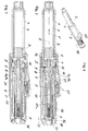
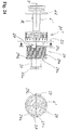
- Figure 1 shows an injection device of a first embodiment.
- the injection device has a first housing part 1 and a second housing part 4, which are detachably connected to one another.
- the housing parts 1 and 4 are screwed together.
- the injection device is designed as a slim injection pen.
- the housing part 1 serves to receive a container 2 filled with fluid product and in this sense forms a reservoir, and the housing part 4 serves as a carrier for a metering and drive device, of which a metering element 18 can be seen.
- the housing part 4 is perforated in the area of the metering element 18, so that a user has direct access to the metering element 18.
- the metering member 18 is rotatably mounted about a central longitudinal axis of the device and is formed as a sleeve which is grooved on its outer circumference in a user-friendly manner.
- a dose indicator 20 can also be seen, which is placed laterally through an opening in the casing of the housing part 4.
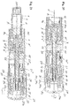
- Figure 2 shows the injection device of the first embodiment in a longitudinal section.
- the container 2 is accommodated in the housing part 1.
- a piston 3 is accommodated so that it can move in a direction of advance V.
- the piston 3 closes the container 2 in a liquid-tight manner at its proximal end.
- product is displaced and poured out through an outlet of the container 2, preferably through an injection needle that projects into the outlet and is attached to the distal end of the housing part 1 by means of a needle holder.
- the container 2 is formed in the manner of conventional ampoules.
- the housing part 1 directly forms a container holder, in the exemplary embodiment an ampoule holder.
- the proximal end of the housing part 1 projects into the housing part 4 and is screwed to the housing part 4.
- the housing part 4 receives a piston rod 15 and the metering and drive device, which is formed as a metering and drive mechanism.
- the metering and drive device comprises a drive member 5 and a clutch 6-11, which in a coupled state, ie in a clutch engagement, couples the drive member 5 to the piston rod 15.
- the Piston rod 15 forms a conveyor with the piston 3.
- coupling members 6-10 transmit a driving force exerted on the driving member 5 to the piston rod 15.
- there is no clutch engagement so that the piston rod 15 is decoupled from the drive member 5.
- the user can adjust the product dose to be administered by a dosing movement of the dosing member 18, in the exemplary embodiment a rotary movement.
- the drive member 5 is sleeve-shaped. It has on its outer surface a thread around a thread axis R pointing in the direction of advance V. With this thread, the drive member 5 is in threaded engagement with a clutch input member 6.
- the clutch input member 6 is also sleeve-shaped and provided with a corresponding internal thread for the thread engagement. The thread pitch in the thread engagement is so large that self-locking cannot occur.
- the dosing member 18 surrounds the clutch input member 6 and is secured against rotation with the clutch input member 6 and axially non-movably connected.
- the piston rod 15 projects into the drive member 5 and the clutch input member 6.
- the piston rod 15 is provided with an external thread over its axial length. With the external thread, it is in threaded engagement with a coupling output member 9, which is provided with a corresponding internal thread. These two threads also have a pitch that prevents self-locking in the thread engagement.
- the thread pitch is preferably less than the thread pitch in the thread engagement between the drive member 5 and the coupling input member 6.
- a coupling sleeve 8 is secured against rotation with the coupling output member 9 and is not axially movably connected.
- the coupling sleeve 8 and the coupling output member 9 can be regarded as a one-piece component with regard to the movements taking place between the drive member 5 and the piston rod 15; however, they are designed in two parts to accommodate a compensating spring 17 and are firmly connected to one another.
- the coupling output member 9 and the coupling sleeve 8 are rotatable about the threaded axis R of the coupling output member 9, but are not axially movable in the housing part 4.
- the piston rod 15 projects through the threaded engagement of the clutch output member 9 and projects into the clutch sleeve 8.
- the compensation spring 17 is clamped, which acts as a compression spring in the direction of advance V on the piston rod 15.
- the compensating spring 17 presses on the piston rod 15 via a plate 15 a which is rotatably supported on the piston rod 15 and forms a flange of a sleeve placed on the piston rod 15.
- the piston rod 15 is not rotatable in a linear guide 4a relative to the housing part 1 in and against the direction of advance V.
- the drive member 5 is also linearly movable relative to the housing part 4 in and against the direction of advance V, for which the housing part 4 directly forms a linear guide 4b.
- the threaded axis of the piston rod 15 forms the main axis of movement of the device.
- the threaded axis of the piston rod 15 forms an axis of movement R. It forms both thread axes. Furthermore, it forms the translation axis for the piston rod 15 and the drive member 5.
- the coupling 6-11 further comprises a coupling intermediate member 7 and a restoring member 10, which is designed as a compression spring, and acts on the coupling intermediate member 7 with an elastic force acting against the direction of advance V.
- the reset member 10 is clamped between the clutch output member 9 and the clutch intermediate member 7.
- Figure 3 shows the injection device in a coupled state.
- the clutch input member 6 and the clutch sleeve 8 form engagement elements which, in the clutch engagement, produce a rotation-proof connection of the two members 6 and 8 around the threaded axis R pointing in the direction of advance V.
- the engagement elements work together as grooves and tongues or toothings, which are formed parallel to the direction of advance V and evenly distributed around the thread axis R.
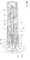
- Figures 4 and 5 show the area of the clutch engagement in detail.
- Figure 4 shows the device in the decoupled and Figure 5 in the coupled state.
- Figure 4 thus corresponds with Figure 2
- Figure 5 corresponds with Figure 3 ,
- the coupling input member 6 has moved away from the coupling sleeve 8 counter to the direction of advance V, so that the coupling input member 6 can be freely rotated relative to the coupling sleeve 8 and the coupling output member 9 firmly connected to it.
- the coupling output member 9 is connected to the housing part 4 in a rotationally secured manner via the coupling sleeve 8, the coupling intermediate member 7 and a decoupling member 11.
- the coupling intermediate member 7 is provided on an inner surface radially facing the coupling sleeve 8 with engaging elements 7b and the coupling sleeve 8 with corresponding engaging elements 8b.
- the coupling intermediate member 7 is provided on an outer circumferential surface with engaging elements 7a and the decoupling member 11 on an inner surface of the jacket with radially facing engaging elements 11a, which in the decoupled state like the engaging elements 7b and 8b in the manner of grooves and tongues or interlocking teeth that are parallel to the direction of advance V.
- the coupling intermediate member 7 is in its rotationally secured engagement with the coupling sleeve 8 and in its rotationally secured engagement with the decoupling member 11 axially movable in and against the direction of advance V, the engagement with the decoupling member 11 being released during a movement in the direction of advance V.
- the drive member 5 If the drive member 5 is actuated by exerting a compressive force on a release element 16 in the advancing direction V, the drive member 5 and the clutch input member 6 together perform an axial clutch stroke of length X. During this drive stroke movement or clutch movement, the clutch input member 6 abuts the intermediate coupling member 7 the restoring elastic force of the restoring member 10 in the direction of advance V. In the course of the lifting movement, the engagement elements 6a and 8a engage with one another, while the coupling intermediate member 7 simultaneously moves relative to the decoupling member 11 until it comes out of the non-rotatable engagement with the decoupling member 11. The intermediate coupling member 7 remains in the non-rotatable engagement with the coupling sleeve 8. The coupling movement is limited by a stop of the release element 16 on the coupling sleeve 8, in the exemplary embodiment on its proximal end face ( Figure 3 ).
- Figure 5 shows the injection device in the coupled state.
- the engagement elements 6a and 8a are in axial overlap, so that the clutch engagement is produced as an anti-rotation engagement between the clutch input member 6 and the clutch sleeve 8.
- the engagement between the coupling intermediate member 7 and the decoupling member 11 is released only after the coupling engagement has been established safely.
- the user rotates the dosing member 18, which locks in easily releasable locking positions.
- the dosing member 18 is secured against rotation and also axially immovably connected to the clutch input member 6 so that it rotates as well.
- the drive member 5 which is linearly guided in and against the advancing direction V at 4b, is moved in the proximal direction and then protrudes from the housing part 4.
- the axial metering path of the drive member 5 results from the angle of rotation by which the metering member 18 is rotated and the thread pitch in the thread engagement between the drive member 5 and the clutch input member 6, which is in the direction of advance V against the Coupling intermediate member 7 and against the direction of advance V against the housing part 4 is at a stop.
- Figure 6 shows the injection device with container 2 still completely full after setting a first dose.
- the user pierces the skin with the injection needle for a subcutaneous injection.
- the user actuates the drive member 5 by pressing it into the housing part 4 in the direction of advance V.
- the clutch movement or the clutch stroke X the drive member 5 takes the clutch input member 6 against the elastic restoring force of the return element 10 until the clutch engagement with the clutch sleeve 8 is established and the non-rotating engagement between the clutch intermediate member 7 and the decoupling member 11 are solved.
- the coupling stroke X is ended and a discharge stroke follows as the second section of the drive movement.
- the drive member 5 is pressed further in the direction of advance V. Since the clutch input element 6 cannot make any further movement in the direction of advance V via the axial stop against the coupling intermediate element 7, it rotates in the thread engagement with the non-rotatably guided drive element 5 around the common thread axis R.
- the clutch input element 6 takes the rotational movement in the clutch engagement Coupling sleeve 8 and this the clutch output member 9 with.
- the coupling sleeve 8 is held together with the coupling output member 9 so that it cannot move axially in the housing part 4.
- the rotary movement of the clutch output member 9 causes the propulsion and thus the discharge movement of the piston rod 15 and thus together the piston 3 via the threaded engagement with the piston rod 15 and its rotationally secured linear guide at 4a.
- the reset member 10 moves the clutch input member 6 back into the clutch intermediate member 7 the clutch engagement removed holding position, as in the Figures 2 and 4 is shown.
- the clutch input element 6 and thus jointly the drive element 5, the metering element 18 and the dose indicator 20 are decoupled from the clutch output element 9 and thus from the piston rod 15 by the disengagement movement of the clutch input element 6.
- the piston rod 15 is connected to the housing part 4 in a manner secured against rotation via the retracting coupling intermediate member 7 and the decoupling member 11.
- Figure 7 shows the injection device at the end of a last distribution with which the container 2 was emptied.
- the housing part 1 is detached from the housing part 4, in the exemplary embodiment by a screwing movement.
- the decoupling member 11 is automatically moved relative to the housing part 4 against the direction of the clutch movement of the clutch input member 6, in the exemplary embodiment against the direction of advance V.
- the housing part 4 supports the decoupling member 11 accordingly.
- the axial path covered by the decoupling member 11 relative to the housing part 4 is as long as the clutch stroke X, so that the decoupling member 11 after loosening the housing parts 1 and 4 blocks the clutch input member 6 axially opposite it and the clutch input member 6 no longer in the Direction of advance V can be moved, at least not in the clutch engagement with the clutch sleeve 8.
- the blocking of the clutch input member 6 in the disengaged position prevents the clutch output member 9 from being locked against rotation with the housing part 4 and thereby preventing the piston rod 15 from being pushed back. In other words, it is ensured that the piston rod 15 can be pushed back into the housing part 4 without blocking.
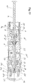
- Figure 8 shows the decoupling member 11 and the first housing part 1 in a perspective view.
- the decoupling member 11 is a sleeve part and has three engaging elements 12 projecting radially inwards in a distal section and a fixing element 13 projecting radially outwards in a proximal section.
- Figure 9 shows the housing part 1 and a connecting portion of the housing part 4, wherein the hidden decoupling member 11 is shown in dashed lines.
- the decoupling member 11 is rotatably and axially movably received in the connecting section of the housing part 4.
- the relative mobility is determined by an axial guide 4e and a circumferential guide 4c, along which the engaging element 13 moves in succession when the housing part 1 is detached from the housing part 4.
- the circumferential guide 4c extends at right angles to the axial guide 4e in the circumferential direction around the screw axis. It is formed as an opening or recess in the housing part 4.
- the decoupling member 11 is in a guide engagement with the housing part 1.
- a guiding curve 1a is formed on an outer jacket surface of the housing part 1 per engaging element 12, which guides the engaging element 12 and thus the decoupling member 11 when the housing parts 1 and 4 are released.
- a further spaced, parallel guide curve 1a guides the decoupling member 11 accordingly when the housing parts 1 and 4 are connected ( Fig. 10 ).
- the guide curve 1 a runs obliquely in a distal section, ie with an incline, to the screw axis of the screw connection of the housing parts 1 and 4, so that when the relative rotation between the housing parts 1 and 4 is required for loosening, the engagement element 12 slides along the guide curve 1 a executes an axial movement of the decoupling member 11 relative to the housing part 4 against the direction of advance V until the fixing element 13 reaches the axial height of the circumferential guide 4c.
- the slope is about 45 ° and is constant.
- the decoupling member against that to be carried out by the coupling input member for engaging Coupling movement X causes.
- a distal section of the guide curve 1a extends axially, so that when the housing parts 1 and 4 are screwed further apart, the fixing element 13 is moved along the circumferential guide 4c. The fixing element 13 slides in the course of this relative circumferential movement between the decoupling member 11 and the housing part 4 via a fixing element 4d in the area of the circumferential guide 4c.
- the fixing element 4d is formed as a cam on a strip section of the housing part 4.
- the strip section acts as a spiral spring firmly clamped on both sides, which yields resiliently when the fixing element 13 moves via the fixing element 4d, in order then to spring back again into its starting position and to form a releasable locking engagement for the decoupling element 11.
- the fixing element 13 In the latching position, the fixing element 13 is fixed in one circumferential direction on the fixing element 4d and in the other circumferential direction on a shoulder formed in the circumferential guide 4c and thereby in both circumferential directions.
- Figure 10 shows the two housing parts 1 and 4 and the decoupling member 11 after its fixing element 13 has been moved behind the fixing element 4d of the housing part 4.
- the decoupling member 11 is secured against rotation and axially fixed to the housing part 4 via the fixing elements 4d and 13 with the housing part 4 and in this way on the housing part 4.
- the decoupling member 11 blocks the clutch input member 6 and thereby ensures the decoupling of the drive member 5 and the piston rod 15.
- its engagement element 12 moves when the housing parts 1 and 4 are screwed further apart from the guide engagement with the guide curve 1a.
- the guide curve 1a is shaped accordingly.
- the dose indicator 20 of the first exemplary embodiment is coupled to the drive element 5 via a display coupling element 21 and the coupling input element 6.
- the display coupling member 21 is connected to the clutch input member 6 in such a way that it cannot rotate in the exemplary embodiment, in that it forms a ring on the clutch member 6 and can be moved relative to the latter in and against the direction of the clutch movement X.
- the display coupling member 21 can be rotated in the opposite direction to the housing part 4 about the axis of rotation R, but is held axially immovable relative to the housing part 4.
- the display coupling member 21 has all around a toothing, which is formed in the exemplary embodiment as a conical toothing with which it meshes with a gear of the dose indicator 20 in order to initiate the metering movement and also the drive movement in the gear.
- the Figures 11 to 18 show an injection device of a second embodiment.
- the injection device of the second exemplary embodiment has some modifications with respect to the coupling and decoupling of the drive member 5 and the piston rod 15 compared to the device of the first exemplary embodiment.
- the drive member 5 and the piston rod 15 itself and also the basic interaction when coupling and decoupling have remained the same.
- the components that are functionally the same are provided with the same reference numerals as in the first exemplary embodiment. In order to indicate modifications, the components in question are provided with the same, but apostrophied, reference numerals.
- Figure 11 shows the injection device in the idle state, in which the drive member 5 is decoupled from the piston rod 15.
- the first housing part 1 is covered with a protective cap 37 which is connected to the housing part 4 and which is removed for the product administration.
- the clutch engagement between the modified clutch input member 6 'and the modified clutch intermediate member 7' is established and released.
- Figure 12 shows the injection device of the second embodiment in the coupled state, which by the action of the trigger element 16 and thus the Drive member 5 and the clutch input member 6 'is produced by a driving force acting in the forward direction V.
- the protective cap 37 has been replaced by a housing part 38 which is placed on the housing part 4 and snapped with it.
- the housing part 38 supports a needle guard 39, preferably in the form of a needle guard sleeve, which is resiliently movable against the direction of advance V.
- the needle guard 39 springs into the housing part 38 against the direction of advance V; in reverse of this movement, the needle protrudes through a distal opening of the needle guard 39.
- the Figures 13 and 14 show the area of clutch engagement in detail, wherein Figure 13 for the decoupled state and Figure 14 the coupled state is.
- the engagement elements 6a and 7c between which the clutch engagement is established, have an inclination to the direction of advance V.
- the engaging elements 6a and 7c are each formed in the manner of a bevel gear ring running around the threaded axis of the piston rod 15.
- the coupling input member 6 ' forms its engaging elements 6a at its distal end as an inner cone
- the coupling intermediate member 7' forms the engaging elements 7c at its proximal end as an outer cone.
- the conical engagement surfaces are congruent to one another and lie axially facing one another with the clear distance X directly opposite. Instead of being conical, the coupling surfaces could also be congruently convex / concave.
- the coupling intermediate member 7 ′ can be moved axially and is locked against rotation in every axial position with the coupling output member 9 in engagement. It is again formed as a sleeve part and is axially slidably mounted on the coupling output member 9. For this purpose, it passes through the axially correspondingly slotted coupling sleeve 8 ', which, however, is not visible in the figures.
- the anti-rotation connection is created in a form-fitting manner by means of engagement elements which are formed as axially straight toothings.
- the restoring element 10 ' which is the same after training and installation, but reduced in function, is the same as in the first Embodiment between the coupling output member 9 and the coupling intermediate member 7 'stretched and acts on the latter against the direction of advance V with an elastic force.
- the restoring member 10' presses the coupling intermediate member 7 'into the rotationally secured engagement with the decoupling member 11'.
- the corresponding engaging elements are again designated 7a and 11a.
- the engaging elements 7a and 11a are also formed as conical ring gears.
- the engagement of coupling intermediate member 7 'and decoupling member 11' can alternatively be purely frictional. In this case, the engagement elements 7a and 11a have congruent friction surfaces facing one another, in the exemplary embodiment these would be the cone surfaces facing one another.
- the metering element 18 ' cannot be moved relative to the housing part 4 in the direction of the coupling movement X, in the exemplary embodiment the axial direction.
- the clutch input member 6 ' is again secured against rotation, but is connected to the metering member 18' in an axially movable manner.
- the anti-rotation engagement between the clutch input member 6 'and the metering member 18' is in the decoupled state of the drive member 5 and the piston rod 15 and is released in the course of the clutch stroke X, namely immediately before the anti-rotation connection between the clutch output member 9 and the housing part 4 is released.
- the coupling input member 6 'and the metering member 18' are provided with engagement elements 6b and 18a which are formed on radially facing lateral surfaces of the two members 6 'and 18' in the manner of grooves and tongues.
- FIG Figures 11 and 12 directed. In the in Figure 11 shown decoupled state is the anti-rotation connection, and in the in Figure 12 shown coupled state is solved.
- the reset member 10 'in the second embodiment has none Coupling members 6 'and 9 separating effect.
- the holding device of the second exemplary embodiment comprises a reset element 14, a support structure 6c and the metering element 18 '.
- the restoring member 14 acts on the clutch input member 6 'via the support structure 6c with an elastic restoring force which counteracts the clutch movement X of the clutch input member 6'.
- the restoring member 14 is supported on the metering member 18 ', which forms a support shoulder for this.
- the support structure 6c is immovably connected to the clutch input member 6 'in and against the direction of the clutch movement X. It is formed as a short sleeve with an outer flange on which the reset member 14 is supported. The support structure 6c lies against the direction of the coupling movement X with respect to the housing part 4. Due to the clutch movement X, the clutch input member 6 'is moved into the clutch engagement with the clutch intermediate member 7' against the elastic restoring force of the reset member 14. As in the first exemplary embodiment, the resetting member 14 is formed as a compression spring which is acted upon by a compressive force in the direction of the coupling movement X.
- the operation of the modified clutch 6'-11 ', 14' is the same as the clutch of the first embodiment.
- the coupling output member 9 is connected to the housing part 4 in a rotationally secured manner via the coupling sleeve 8 ', the coupling intermediate member 7' and the decoupling member 11 '.
- the injection button 16 By actuating the injection button 16 and thus the execution of the clutch stroke X ( Figure 11 ) the clutch engagement is established, in the second embodiment between the clutch input member 6 'and the clutch intermediate member 7'.
- the engagement elements 6a and 7c engage in one another, so that the clutch input element 6 'is connected to the clutch output element 9 in a rotationally secured manner via the clutch intermediate element 7' and the clutch sleeve 8 '. Only after production of the non-rotating engagement is the coupling member 7 'moved out of engagement with the decoupling member 11' by the clutch input member 6 'pushing in the forward direction V, so that the clutch output member 9 can rotate freely around the threaded axis R formed with the piston rod 15 and the Clutch engagement is fully established.
- Figure 14 shows the injection device in the coupled state, ie in the clutch engagement.
- the Figures 15 and 16 correspond to the Figures 6 and 7 of the first embodiment, so that it can be referred to.
- Figure 17 shows the injection device of the second embodiment during the exchange of the reservoir 2. After the reservoir 2, as in Figure 16 is shown, emptied, the housing part 1 is released from the housing part 4, whereby the decoupling member 11 'is moved into the decoupling position.
- This function corresponds entirely to that of the decoupling member 11 of the first embodiment, so that the explanations there and the Figures 8-10 can be referred.
- the housing part 1 already takes on the new reservoir 2.
- the housing part 1 can be moved towards the housing part 4 with the piston 3 closing the reservoir 2 proximally.
- the piston rod 15 projecting freely from the housing part 4 is moved back by the pressing piston 3 in threaded engagement with the freely rotatable but axially fixed clutch output member 9.
- the piston rod 15 performs an axial linear movement when pushed back, while the coupling output member 9 rotates freely together with the coupling sleeve 8 'about the common thread axis.
- the piston rod 15 can also be moved back directly onto its plunger by pressure.
- Figure 18 shows the coupling area with the decoupling member 11 'located in the decoupling position in detail.
- the function of the decoupling member 11 ' corresponds to that of the first exemplary embodiment, namely blocking the clutch input member 6' in the moved-off axial position.
- the metering movement and the drive movement are likewise initiated via a clutch input element 6 ′ and a display coupling element 22 into a gearbox of the dose display 20 ′.
- the display coupling member 22 is also secured against rotation with the clutch input member 6 'and is not movable relative to the housing part 4 in and against the direction of the clutch movement X.
- the Figures 19 to 24 show as a third embodiment an injection device in which the driving force for the product distribution is not applied manually but by a drive member 25, which is formed as a drive spring.
- the drive member 25 is tensioned by adjusting the dose to be administered.
- the spring energy absorbed during the dose setting is released when the device is triggered and converted into propulsion of the piston rod 15.
- Figure 19 shows the injection device of the third embodiment complete with the assembled housing part 38 and the needle guard 39 slidably received therein against the direction of advance V against the force of a return spring.
- FIGS. 20 and 21 show the housing part 4 with the components of the injection device accommodated therein, Figure 20 in an idle state comparable to the previous exemplary embodiments, in which the dose can be set, and Figure 21 in clutch engagement. Unless otherwise stated below, the Figures 20 and 21 referred to.
- the drive member 25 is a spiral spring acting as a torsion spring with spring windings which rotate around the thread axis R of the thread engagement between the clutch output member 9 and the piston rod 15.
- the spring windings are arranged one above the other radially to the thread axis R; they have a zero slope to the thread axis.
- An inner end of the spring windings is fastened to the clutch input member 6 ', and an outer end is fastened to a support structure 26 which is connected to the housing part 4 in the direction of the clutch movement X but is secured against rotation.
- the support structure 26, is connected to the clutch input element 6 ′ so that it cannot move in and against the direction of the clutch movement X.
- the Coupling input member 6 ' is rotatable about the threaded axis R relative to the support structure 26.
- Another support structure 6d is connected to the coupling input member 6 'so that it cannot be moved in and against the direction of the coupling movement X; in the exemplary embodiment, the clutch input member 6 'and the support structure 6d are formed in one piece.
- the drive member 25 is axially surrounded by the support structures 6d and 26.
- the function of the coupling corresponds to that of the second exemplary embodiment, so that the same reference numerals are used for the coupling elements 6'-10 'and the decoupling element 11'.
- the intermediate coupling member 7 ' is directly in engagement with the clutch output member 9 in an engagement which transmits the rotational drive movement of the clutch input member 6' to the clutch output member 9.
- a rotation lock is formed between the clutch housing 6' and the housing part 4.
- the rotation lock consists in the illustrated holding position of the coupling members 6 ', 7' and 9 between a first locking member 24 and a second locking member 34.
- the locking member 24 is connected to the clutch input member 6 'in a manner secured against rotation.
- the locking member 34 is secured against rotation with the housing part 4, but relative to the housing part 4 and the Coupling input member 6 'in and against the direction of the clutch movement X movable.
- the locking members 24 and 34 form with their end faces in contact with each other in locking engagement a ratchet which permits a rotational movement of the clutch input member 6 'exciting the drive member 25 and prevents a rotational movement in the opposite direction.
- Figure 24 shows the clutch input member 6 'with the locking member 24 mounted thereon in a rotationally secured manner, the display coupling member 23 secured against rotation with the coupling input member 6' and a connecting part 33 which is not movably connected to the input member 6 '.
- the display coupling member 23 forms and is a unit counter ring of the dose indicator 20 "
- the locking member 24 is provided on a proximal end face facing the locking member 34 with locking teeth 24a evenly arranged around the axis R, which interact with counter teeth of the locking member 34 in locking engagement
- the locking element 24 is provided with a thread 24b for a second function in connection with the metering and distribution on an outer surface of the jacket, the thread axis of which coincides with the thread axis R of the piston rod 15.
- the stop member 27 In the thread 24b engages a stop member 27.
- the stop member 27 is guided such that it can move linearly parallel to the thread axis R, in the exemplary embodiment in an axial groove on the inner circumferential surface of the housing part 4.
- the blocking member 24 forms a twist stop 24c for the stop member 27, which causes the drive movement of the clutch input member 6 which drives the piston rod 15 ' limited. It forms a further rotation stop 24d for the stop member 27, which determines the pourable and adjustable maximum dose.
- On the other side of the threaded axis R is the view in the Figure 23
- a recognizable stop member 27 is arranged opposite another stop member 27, which cooperates in the same way with two further rotation stops 24c and 24d.
- the 24d thread is double-threaded.
- the stop members 27 simultaneously come into abutment against the respectively assigned rotation stops 24c and 24d, as in the cross-sectional illustration of FIG Figure 23 for the twist stops 24c.
- the twist stops 24c determine a zero dose position and the twist stops 24d determine a maximum dose position.
- the holding device is formed in a third variant. It comprises a reset member 19, furthermore the display coupling member 23 and the locking member 24.
- the reset member 19 is supported in the direction of the coupling movement X via the display coupling member 23 on the housing part 4 and against the direction of the coupling movement X on the locking member 24.
- the restoring member 19 presses the locking member 24 against the connecting part 33.
- the resetting member 19 thus exercises via the locking member 24 and the connecting part 33 the clutch input member 6 'exerts an elastic restoring force which acts against the direction of the clutch movement X and which holds the clutch input member 6' in the holding position disengaged from the clutch engagement. It acts as a compression spring again.
- the locking member 24 is a sleeve part with an outer casing forming the thread 24b, an inner casing serving to secure it against rotation on the coupling input member 6 'and a bottom connecting the two casings on which the locking teeth 24a are formed.
- the reset member 19 protrudes into the cup-shaped locking member 24 and is supported on the bottom of the locking member 24.
- the restoring member 19 presses the locking member 24 not only against the stop against the connecting part 33, but also against a stop against the housing part 4. This further stop prevents the locking member 24 from over the in Figure 20 occupied stop position can be moved against the direction of the clutch movement X.
- the locking member 24 is thus movable relative to the clutch input member 6 'against the restoring elastic force of the restoring member 19 in the direction of the clutch movement X.
- the clutch input member 6 ' is movable relative to the locking member 24 lying against the housing part 4 against the direction of the clutch movement X.
- the compensating spring 17 tensioned between the piston rod 15 and the connecting part 33 supports the reset element 19 in its function of holding the clutch input element 6 'in the holding position.
- the compensating spring 17 could for the disengagement Coupling members 6 ', 7' and 9 basically replace the resetting member 19. However, it is preferably so weak that, at least after partial relaxation, it can no longer hold the coupling members 6'-9 in the holding position with sufficient certainty and thus the coupling in the disengaged state.
- a trigger element 28 is provided for triggering the drive member 25.
- the trigger element 28 is translatory relative to the housing part 4 in the direction of the coupling movement X, in the exemplary embodiment the forward direction V or the distal direction, and about the axis of rotation R of the clutch input member 6 ', which coincides with the threaded axis R of the piston rod 15 in the exemplary embodiment movable and is guided by the housing part 4 in these two movements.
- the translational movement in the distal direction creates the coupling engagement between the coupling input member 6 'and the coupling intermediate member 7' and the anti-rotation lock between the locking members 24 and 34 is released and the drive member 25, i.e. the distribution, thereby triggered.
- the translatory movement in the direction of advance V is therefore also referred to below as the triggering movement.
- the trigger element 28 forms the metering element of the third exemplary embodiment. Due to the rotational movement of the trigger element 28 relative to the housing part 4, the product dose that can be dispensed with the next dispensing process is set via several intermediate members. This movement is also referred to below as the dosing movement. From the zero dose position in Figure 20 and is determined by abutment of the stop members 27 on the rotation stops 29c of the locking member 24, which limit the drive movement of the clutch input member 6 ', the dose can be adjusted by turning the trigger element 28 in the direction of the arrow indicating the direction of rotation, the metering direction.
- the rotational metering movement of the trigger element 28 is transmitted via an inner part 29, which is connected to the trigger element 28 in a manner secured against rotation and displacement, or is formed integrally therewith, and the connecting part 33 is transmitted to the clutch input element 6 '.
- the inner part 29 and the connecting part 33 are in a rotationally secured engagement with one another, and the connecting part 33 is in engagement with the Coupling input member 6 'connected to prevent rotation.
- the inner part 29 and the connecting part 33 are provided with an internal toothing 29a and an external toothing 33a which engage in one another in the idle state of the device and are axially displaceable relative to one another.
- the trigger element 28 is arranged in a user-friendly manner in the proximal end region of the housing part 4. Its outer sleeve part surrounds the housing part 4. A bottom of the trigger element 28 forms a proximal end of the injection device.
- the trigger element 28 can be operated like a rotary knob and has a corrugation on its outer circumferential surface for this purpose. It can be operated like a push button for triggering.
- the triggering element 28 latches with the housing part 4 in accordance with the dose units in discrete rotational angle positions.
- a stop element 29b projects radially inward, facing a proximal end face of the connecting part 33.
- the connecting part 33 and the stop element 29b which is just large enough that the anti-rotation device between the inner part 29 and the connecting part 33 is released when the triggering element 28 is released, before the stop element 29b releases the relative movement of the Tripping element 28 terminated relative to the connecting part 33 by stop contact.
- the second locking member 34 is tensioned into locking engagement with the locking member 24 by means of a locking spring 31.
- the locking spring 31 is supported in the direction of the coupling movement X on the locking member 34 and the coupling movement X against a housing part 30 which is fixedly connected to the housing part 4.
- the locking member 34 is axially guided by the housing part 4 against rotation.
- the housing part 4 forms a distal and a proximal stop for the mobility of the locking member 34.
- the user adjusts the dose by rotating the trigger element 28 in the metering direction.
- the trigger element 28 takes along the connecting part 33 via the anti-rotation device 29a, 33a, which in turn takes the coupling input member 6 ', which thus carries out the same rotary dosing movement as the trigger element 28.
- the drive member 25 is tensioned by the rotation of the clutch input member 6 '.
- the stop member 27 moves in engagement with the thread 24b of the locking member 24 from the zero dose-determining stop 24c of the thread 24b in the direction of the maximum dose-determining stop 24d ( Fig. 24 ).
- the injection device also offers a convenient possibility of dose correction, as based on the comparison of the Figures 20 and 22 becomes clear. If the user has accidentally set a too high dose, he can correct the dose by turning back the coupling input member 6 '. For the dose correction, he pulls the trigger element 28 in the proximal direction. This disengagement movement of the trigger element 28 is shown in FIG Figure 22 indicated by an arrow, as well as the direction of rotation for the correction. The inner part 29 and the locking member 34 are in the idle state of the device with respect to movement in the proximal direction in a driving engagement. The corresponding drivers are designated 29c and 34a.
- the drivers 29c formed by the inner part 29 and the drivers 34a formed by the locking member 34 engage behind one another and form a hook for the disengagement movement of the release element 28.
- the locking member 34 is thus also moved in the proximal direction against the force of the locking spring 31 and thereby releases from the locking engagement with the locking member 24, which is against the housing part 4 against a stop.
- the user can correct the dose by means of a backward movement of the trigger element 28 and the still existing non-rotating engagement of the inner part 29 with the connecting part 33.
- the user As soon as the user releases the trigger element 28, it snaps back together with the locking element 34 under the action of the locking spring 31 in the distal direction and the locking element 34 thereby again engages in locking engagement with the locking element 24.
- the user expediently continues to hold the trigger element 28 fixed what by the rotational angular locking positions of the trigger element 28 is facilitated. In principle, however, he can also snap it back and, if necessary, dose it again.
- the device After setting the desired dose, the device is placed on the skin at the desired point of administration and the injection needle is inserted.
- the trigger element 28 takes on a further function for inserting the needle, for which purpose it is combined with the needle guard 39 ( Figure 19 ) is coupled.
- a first phase of the insertion the user presses the injection device against the skin, so that the needle guard 39 moves in the distal direction relative to the housing part 38.
- the injection needle is not yet exposed by this first part of the movement of the needle guard 39; rather, its tip is still behind the needle guard 39.
- the needle guard 39 comes to a stop against a resistance element, so that it cannot move any further in the distal direction relative to the housing part 38. If pressure is still exerted on the injection device in the direction of the skin, the user presses the trigger element 28 in the proximal direction.
- the release element 28 releases a stop contact between the needle guard 39 and the resistance element, so that the injection device and thus the injection needle are moved relative to the needle guard 39 in the direction of the skin and the injection needle sticks.
- the drive member 25 can be triggered by further pressure on the trigger element 28 and the distribution can be effected.
- the release element 28 and thus the inner part 29 are pressed further against the pressure of the spring 32 relative to the connecting part 33 in the distal direction, so that the anti-rotation device 29a , 33a triggers.
- the trigger element 28 can turn empty.
- the stop element 29b comes into stop contact with the connecting part 33.
- the release element 28 presses the connecting part 33 and thus the coupling input member 6 'in the direction of the stop element 29b Coupling movement X, in the exemplary embodiment in the direction of advance V.
- the locking member 34 follows this movement until it comes to a stop against the housing part 4.
- the clutch input member 6 ' engages with the clutch intermediate member 7'.
- the clutch input member 6 ' presses the clutch intermediate member 7' against the force of the reset member 10 'from the frictional locking engagement with the decoupling member 11'.
- the locking member 34 comes to a stop with the housing part 4.
- the trigger element 28 presses over the connecting part 33 the locking member 24 from locking engagement with the locking member 34.
- Figure 21 shows the injection device for the case of setting a zero dose or a low priming dose in the coupled state after releasing the anti-rotation lock 24, 34, ie after the trigger element 28 has carried out the trigger movement completely.
- the triggering sequence described above runs automatically, advantageously with the pressure exerted continuously on the triggering element 28, from the piercing to the complete delivery of the set dose.
- Figure 23 shows the injection device after emptying the container 2.
- the housing part 1 has already been removed from the housing part 4.
- the piston rod 15 assumes its most distal position.
- the decoupling member 11 ' blocks the clutch input member 6' in the position moved away from the coupling intermediate member 7 '.
- the functioning of the decoupling element 11 ' corresponds to that in the other exemplary embodiments. In contrast to the first two exemplary embodiments, however, the housing part 1 and the decoupling member 11 'are not directly in guide engagement with one another, but rather via an adapter structure 36.
- the adapter structure 36 is a sleeve which is located in the housing part 4 in which connecting section in and against the direction of Coupling movement X is fixed, but can rotate about the central longitudinal axis R of the housing part 4.
- the adapter structure 35 forms a guide curve 36a either as a recess or opening in its outer surface facing the decoupling member 11 '.
- the guide curve 35a has the course of a threaded section.
- the length measured over the circumference and the slope of the guide curve 35a measured with respect to the central longitudinal axis of the housing part 4 are dimensioned such that with a quarter to a half turn of the adapter structure 35 relative to the decoupling member 11 'into the in FIG Figure 21 shown decoupling position is moved.
- the decoupling member 11 ' engages with the engaging element 12 in the guide curve 35a.
- the adapter structure 35 forms a linear guide for the housing part 1.
- the housing part 1 is inserted into the adapter structure 35, preferably with a slight frictional engagement and accordingly a sliding guide for the housing part 1.
- the housing part 1 cannot be rotated relative to the adapter structure 35 about the central longitudinal axis of the housing part 4.
- the correspondingly non-rotating engagement is produced right at the beginning of the insertion of the housing part 1 into the adapter structure 35.
- the housing part 1 After the housing part 1 has been pushed in as far as it will go against the housing part 4, namely its coupling seat at 4a, the housing part 1 is rotated relative to the housing part 4 and takes the adapter structure 36 with it during this rotary movement until the engaging element 12 of the decoupling member 11 ' comes to a stop at the end of the guide curve 36a.
- the rotational movement of the housing part 1 is preferably only possible in its axial stop position, for which purpose an anti-rotation device that is effective into the stop position can also be formed between the housing parts 1 and 4.
- the movement of the decoupling member 11 'caused in the guide engagement has an axial length which is greater than the length X of the complete coupling movement.
- the decoupling member 11 presses the coupling input member 6' beyond its holding position assumed in the idle state and blocks it in this decoupling position.
- the clutch input member 6 takes the trigger element 28 with it via the stop element 29b.
- the locking member 34 is also taken against the force of the locking spring 31 and moved out of the locking engagement.
- the locking member 24 can not follow the locking member 34 because it is against the housing part 4 on the stop.
- the anti-rotation lock is thus released by means of the decoupling mechanism which the housing parts 1 and 4 form via the adapter structure 35 with the decoupling member 11 '. If the clutch input element 6 'is not yet in the zero dose position, the drive element 25 now rotates it into the zero dose position at the latest and the dose indicator 20 "is zeroed.
- the special advantage of the coupling between the dose indicator 20" and the clutch input element 6 should be repeated 'pointed out that with every distribution the dose display 20 "of the dose delivered is reset accordingly. If the set dose has not been distributed, for example because the injection process has been interrupted or the container 2 did not contain the set dose completely, the user can read this from the dose display 20 "which is only partially reset in this case.
Landscapes
- Health & Medical Sciences (AREA)
- Engineering & Computer Science (AREA)
- Hematology (AREA)
- Life Sciences & Earth Sciences (AREA)
- Vascular Medicine (AREA)
- Anesthesiology (AREA)
- Biomedical Technology (AREA)
- Heart & Thoracic Surgery (AREA)
- Veterinary Medicine (AREA)
- Public Health (AREA)
- Animal Behavior & Ethology (AREA)
- General Health & Medical Sciences (AREA)
- General Engineering & Computer Science (AREA)
- Mechanical Engineering (AREA)
- Environmental & Geological Engineering (AREA)
- Infusion, Injection, And Reservoir Apparatuses (AREA)
Abstract
Die Erfindung betrifft eine Förder- und Dosiereinrichtung zum Einstellen und Ausschütten einer auszuschüttenden Dosis aus einer Vorrichtung, umfassend ein Gehäuseteil (4) als Träger für eine Förder- und Dosiereinrichtung der Vorrichtung; eine vom Gehäuseteil (4) gehaltene Kolbenstange (15); ein vom Gehäuseteil (4) gehaltenes Antriebsglied (5), wobei das Antriebsglied (5) mit der Kolbenstange (15) so gekoppelt ist, dass eine Betätigung des Antriebsglieds (5) automatisch eine Ausschüttbewegung der Kolbenstange (15) bewirkt, durch die ein Produkt ausgeschüttet wird. Dabei umfasst die Förder- und Dosiereinrichtung weiter ein Dosierglied (18) umfasst, mit dem das Antriebsglied (5) so gekoppelt ist, dass eine Dosierbewegung des Dosierglieds (18) eine Dosierbewegung des Antriebsglieds (5) zur Folge hat, wobei das Antriebsglied (5) relativ zum Gehäuseteil (4) in und gegen eine Vortriebsrichtung bewegbar lineargeführt ist, wofür das Gehäuseteil (4) unmittelbar eine Linearführung (4b) bildet.

Description
Die Erfindung betrifft eine Vorrichtung zur Verabreichung eines fluiden Produkts. Die Vorrichtung kann insbesondere ein Injektionsgerät sein, vorzugsweise ein Injektionspen, bevorzugt für die Selbstverarbeitung. Injektionsgeräte sind beispielsweise aus der Diabetestherapie, der Verabreichung von Wachstumshormonen oder Osteoporosepräparaten bekannt. Derartige Geräte sollen einerseits die Gewähr dafür bieten, dass die richtige Dosis verabreicht wird, andererseits sollen die Geräte einfach und bequem bedienbar sein.The invention relates to a device for administering a fluid product. The device can in particular be an injection device, preferably an injection pen, preferably for self-processing. Injection devices are known, for example, from diabetes therapy, the administration of growth hormones or osteoporosis preparations. Such devices should on the one hand guarantee that the correct dose is administered, on the other hand the devices should be simple and convenient to use.
Ein aus der
Ein Injektionsgerät mit einer der Kopplung von Kolbenstange und Antriebsglied vergleichbaren Mechanik ist aus der
Es ist eine Aufgabe der Erfindung, eine Vorrichtung zur Verabreichung eines fluiden Produkts zu schaffen, die den Austausch eines entleerten Reservoirs auf einfache, aber dennoch sichere Weise gestattet.It is an object of the invention to provide a device for administering a fluid product, which allows the replacement of an emptied reservoir in a simple but nevertheless safe manner.
Die Erfindung betrifft eine Vorrichtung zur Verabreichung eines fluiden Produkts, die wenigstens zwei lösbar miteinander verbundene Gehäuseteile aufweist, von denen ein erstes ein Reservoir für das Produkt oder vorzugsweise für ein Produktbehältnis und ein zweites einen Träger für eine Fördereinrichtung bildet. Die Fördereinrichtung ist vorzugsweise zu einer Förder- und Dosiereinrichtung weitergebildet, mit der eine auszuschüttende Dosis des Produkts einstellbar ist. Die Fördereinrichtung umfasst eine von dem zweiten Gehäuseteil gehaltene Kolbenstange und ein ebenfalls von dem zweiten Gehäuseteil gehaltenes Antriebsglied für die Kolbenstange. Das Antriebsglied ist mit der Kolbenstange so gekoppelt, vorzugsweise rein mechanisch, dass eine Betätigung oder Auslösung des Antriebsglieds automatisch eine Ausschüttbewegung der Kolbenstange bewirkt, durch die das Produkt ausgeschüttet wird. Das Produkt kann beispielsweise Insulin, ein Wachstumshormon, ein Osteoporosepräparat oder ein anderes Medikament oder grundsätzlich auch ein Nichtmedikament sein, das dem Menschen oder gegebenenfalls einem Tier verabreichbar ist. Die Fördereinrichtung umfasst ferner eine Kupplung, die in einem Kupplungseingriff das Antriebsglied mit der Kolbenstange koppelt.The invention relates to a device for administering a fluid product, which has at least two detachably connected housing parts, a first of which forms a reservoir for the product or preferably for a product container and a second forms a carrier for a conveying device. The conveying device is preferably developed into a conveying and metering device with which a dose of the product to be distributed can be set. The conveying device comprises a piston rod held by the second housing part and a drive member for the piston rod likewise held by the second housing part. The drive member is coupled to the piston rod, preferably purely mechanically, such that actuation or triggering of the drive member automatically causes the piston rod to be discharged, through which the product is discharged. The product can be, for example, insulin, a growth hormone, an osteoporosis preparation or another medicament or in principle also a non-medication which can be administered to humans or, if appropriate, to an animal. The conveying device further comprises a clutch which couples the drive member to the piston rod in a clutch engagement.
Um das Reservoir beispielsweise im Falle der Entleerung möglichst einfach und rasch austauschen zu können, ist nach der Erfindung ein Entkopplungsglied vorgesehen, für das ebenfalls das zweite Gehäuseteil den Träger bildet und das im verbundenen Zustand der Gehäuseteile mit dem ersten Gehäuseteil gekoppelt ist, vorzugsweise durch einen mechanischen Eingriff, der unmittelbar zwischen dem Entkopplungsglied und dem ersten Gehäuseteil besteht. Die Kopplung ist so gebildet, dass das Entkopplungsglied durch eine Relativbewegung der Gehäuseteile zueinander, durch die die Gehäuseteile voneinander gelöst werden, relativ zu dem zweiten Gehäuseteil in eine Entkopplungsposition bewegt wird, in der es die Kolbenstange von dem Antriebsglied entkoppelt. Das Entkopplungsglied hält die Kupplung in einem ausgerückten Zustand, d.h. für die Ausschüttung im Kupplungseingriff befindliche Kupplungsglieder werden von dem Entkopplungsglied voneinander separiert und der Kupplungseingriff verhindert, falls nötig gelöst.In order to be able to replace the reservoir as easily and quickly as possible, for example in the event of emptying, a decoupling element is provided according to the invention, for which the second housing part likewise forms the support and which, when the housing parts are connected, is coupled to the first housing part, preferably by one mechanical engagement that exists directly between the decoupling member and the first housing part. The coupling is formed in such a way that the decoupling member is moved relative to the second housing part into a decoupling position by a relative movement of the housing parts to one another, by means of which the housing parts are separated from one another, in which it decouples the piston rod from the drive member. The decoupling member keeps the clutch in a disengaged state, ie for the Discharge in coupling engagement coupling members are separated from each other by the decoupling member and the coupling engagement is prevented, if necessary released.
Wegen der Entkopplung kann bei einem Reservoirwechsel die üblicherweise ausgefahrene Kolbenstange zurückgesetzt, d.h. eingefahren werden, ohne auf das Antriebsglied zu wirken. Falls das Antriebsglied, wie dies bevorzugten Ausführungen entspricht, mit einer Dosisanzeige und/oder einem Dosierglied gekoppelt ist, wirkt die einfahrende Kolbenstange vorzugsweise auch nicht auf die Dosisanzeige und/oder das Dosierglied zurück. Der Benutzer muss dementsprechend nach einem Reservoirwechsel weder bei dem Antriebsglied noch bei einer oder einem gegebenenfalls vorhandenen Dosieranzeige oder Dosierglied Korrekturen vornehmen.Because of the decoupling, the usually extended piston rod can be reset when changing the reservoir, i.e. be retracted without affecting the drive link. If the drive member, as is the case with preferred embodiments, is coupled to a dose indicator and / or a metering element, the retracting piston rod preferably also does not react to the dose indicator and / or the metering element. Accordingly, the user does not have to make any corrections to the drive element or to a metering indicator or metering element, if any, after changing the reservoir.
In bevorzugten Ausführungen, in denen die Vorrichtung mit der Fähigkeit ausgestattet ist, die mittels eines Ausschüttvorgangs ausschüttbare Dosis einzustellen, kann die Einstellbarkeit so gestaltet sein, dass sie einmalig beispielsweise von einem Arzt vorgenommen wird und der Benutzer sich dann pro Ausschüttvorgang stets die einmal eingestellte Dosis verabreicht. Bevorzugter ist die Dosis für jeden Ausschüttvorgang einzeln einstellbar, so dass ein Verwender, der sich das Produkt selbst verabreicht, die Dosen flexibel dem Bedarf angepasst einstellen kann. Eine Vorrichtung, die das Einstellen der Dosis gestattet, umfasst ein Dosierglied, das von dem Antriebsglied gebildet werden kann oder bevorzugter zusätzlich zu dem Antriebsglied vorgesehen und mit dem Antriebsglied so gekoppelt ist, vorzugsweise rein mechanisch, dass eine Dosierbewegung des Dosierglieds eine Dosierbewegung des Antriebsglieds zur Folge hat. In bevorzugter Ausführung ist eine Dosisanzeige zum Anzeigen der eingestellten Produktdosis vorgesehen. Die Anzeige kann eine akustische und/oder taktile und/oder insbesondere eine optische sein. Die Dosisanzeige ist mit dem Dosierglied und vorzugsweise auch mit dem Antriebsglied, falls das Antriebsglied nicht bereits das Dosierglied bildet, so gekoppelt, dass eine Bewegung, die das Dosierglied bei einer Einstellung der Produktdosis ausführt, eine Änderung der angezeigten Produktdosis bewirkt. Vorteilhafterweise entkoppelt das Entkopplungsglied in der Entkopplungsposition die Dosisanzeige und/oder das Dosierglied falls ein solches zusätzlich zum Antriebsglied vorgesehen ist, von der Kolbenstange, besonders bevorzugt auf die gleiche Weise wie es das Antriebsglied von dem Förderglied entkoppelt. Gegebenenfalls kann die Entkopplung jedoch auch an einer anderen Stelle einer zwischen dem Förderglied und dem Dosierglied und/oder dem Förderglied und der Anzeige bestehenden Kopplung herbeigeführt werden, indem die in diesem Fall weitere Kupplung an der betreffenden Schnittstelle in einem ausgerückten Zustand gehalten wird.In preferred embodiments, in which the device is equipped with the ability to set the dose that can be dispensed by means of a dispensing process, the adjustability can be designed such that it is carried out once by a doctor, for example, and the user then always selects the dose that has been set once per dispensing process administered. The dose is more preferably individually adjustable for each dispensing process, so that a user who administers the product himself can adjust the doses flexibly to suit the need. A device which allows the dose to be set comprises a metering member which can be formed by the drive member or, more preferably, is provided in addition to the drive member and is coupled to the drive member, preferably purely mechanically, in such a way that a metering movement of the metering member counteracts a metering movement of the drive member Consequence. In a preferred embodiment, a dose display is provided for displaying the set product dose. The display can be an acoustic and / or tactile and / or in particular an optical one. The dose indicator is coupled to the dosing member and preferably also to the drive member, if the drive member does not already form the dosing member, in such a way that a movement which the dosing member executes when the product dose is set changes the displayed product dose. In the decoupling position, the decoupling member advantageously decouples the dose indicator and / or the dosing member, if such is provided in addition to the drive member, from the piston rod, particularly preferably in the same way as it decouples the drive member from the conveying member. If necessary, however, the decoupling can also be brought about at another point of a coupling existing between the conveying element and the metering element and / or the conveying element and the display, in that the further coupling in this case is kept in a disengaged state at the relevant interface.
Für die Einstellung der Dosis ist das Antriebsglied vorzugsweise auch im verbundenen Zustand der Gehäuseteile von dem Förderglied entkoppelt. Falls die Vorrichtung zusätzlich mit einer Dosisanzeige und/oder einem Dosierglied ausgestattet ist, ist vorzugsweise auch die Dosisanzeige und/oder das Dosierglied für die Einstellung der Dosis von dem Förderglied entkoppelt, wenn die Gehäuseteile miteinander verbunden sind. In ebenfalls bevorzugter Ausführung kann eine Dosisanzeige und/oder ein Dosierglied für die Einstellung der Dosis von dem Förderglied entkoppelt sein, während das Antriebsglied während der Einstellung mit dem Förderglied gekoppelt ist. Die Entkopplung ermöglicht die freie Dosiswahl, d.h. die Dosis kann erhöht oder verringert werden ohne Rückwirkung auf die Kolbenstange.For setting the dose, the drive member is preferably decoupled from the conveying member even when the housing parts are connected. If the device is additionally equipped with a dose indicator and / or a dosing element, the dose indicator and / or the dosing element for setting the dose is preferably also decoupled from the conveying element when the housing parts are connected to one another. In a likewise preferred embodiment, a dose display and / or a dosing member for setting the dose can be decoupled from the delivery member, while the drive member is coupled to the delivery member during adjustment. The decoupling enables free dose selection, i.e. the dose can be increased or decreased without affecting the piston rod.
Falls das Antriebsglied für die Einstellung der Dosis von dem Förderglied entkoppelt ist, wird es durch eine Kupplungsbewegung mit dem Förderglied gekoppelt, um dessen Ausschüttbewegung zu bewirken.If the drive member for setting the dose is decoupled from the conveying member, it is coupled to the conveying member by means of a coupling movement in order to effect its dispensing movement.
Die Antriebskraft wird in einer ersten Ausführung manuell und in einer zweiten Ausführung mittels eines Federantriebs, der in solch einer Ausführung das Antriebsglied bildet, aufgebracht. Obgleich weniger bevorzugt, kann die Antriebskraft auch motorisch aufgebracht werden.The driving force is applied manually in a first embodiment and in a second embodiment by means of a spring drive which forms the drive member in such an embodiment. Although less preferred, the driving force can also be applied by motor.
Falls die Antriebskraft manuell aufgebracht wird, ist eine Wegstrecke der Antriebsbewegung in einen Kupplungswegabschnitt und einen sich anschließenden Ausschüttwegabschnitt unterteilt. Nach Zurücklegung des Kupplungswegabschnitts ist das Antriebsglied mit dem Förderglied gekoppelt und treibt danach über den Ausschüttwegabschnitt das Förderglied an. In der zweiten Ausführung, in der die Antriebskraft eine Federkraft oder gegebenenfalls eine Motorkraft ist, wird die Kupplungsbewegung vorzugsweise durch Betätigung eines Auslöseelements bewirkt. Sobald die Kupplung von einer für die Ausschüttung auf das Antriebsglied oder ein Auslöseelement auszuübenden Betätigungskraft oder einer motorischen oder einer gespeicherten Kraft, beispielsweise Federkraft, entlastet wird, löst sich die Kopplung vorzugsweise automatisch. Das Antriebsglied oder bevorzugter ein die Übertragung der Antriebsbewegung bewirkendes Kupplungsglied wird hierfür vorteilhafterweise mit einer der Kupplungsbewegung entgegenwirkenden Rückstellkraft beaufschlagt, um bei Entlastung des Antriebsglieds automatisch die Kopplung zwischen dem Antriebsglied und der Kolbenstange zu lösen. Denkbar wäre es alternativ auch, dass der Verwender die für den Antrieb der Kolbenstange geschlossene Kupplung durch eine manuell bewirkte Bewegung des Antriebsglieds oder alternativ eines weiteren Entkopplungsglieds öffnet, d.h. den Kupplungseingriff löst.If the driving force is applied manually, a distance of the driving movement is divided into a coupling path section and a subsequent discharge path section. After the coupling path section has been covered, the drive member is coupled to the conveyor member and then drives the conveyor member via the discharge path section. In the second embodiment, in which the driving force is a spring force or possibly a motor force, the Coupling movement preferably effected by actuating a trigger element. As soon as the coupling is relieved of an actuating force to be exerted on the drive member or a trigger element or a motor or a stored force, for example spring force, the coupling is preferably released automatically. For this purpose, the drive member or, more preferably, a coupling member which effects the transmission of the drive movement is advantageously subjected to a restoring force which counteracts the clutch movement in order to automatically release the coupling between the drive member and the piston rod when the drive member is relieved. It would alternatively also be conceivable for the user to open the clutch which is closed for driving the piston rod by means of a manually effected movement of the drive member or, alternatively, of a further decoupling member, ie releasing the clutch engagement.
In einer Weiterentwicklung wird in einem Ruhezustand der Vorrichtung der mit der Kolbenstange verbundene, ausgangsseitige Teil der Kupplung an dem zweiten Gehäuseteil so festgelegt, dass die Kolbenstange keine Ausschüttbewegung ausführen kann, sondern bewusst freigegeben werden muss, beispielsweise unmittelbar im Zusammenhang mit einer Ausschüttung. Vorteilhafterweise wird die Kolbenstange mittels des Entkopplungsglieds festgelegt. Vorteilhaft ist es, wenn die Festlegung an dem Gehäuseteil durch die Kupplungsbewegung gelöst wird. Vorzugsweise wird in einer ersten Phase des Kupplungswegabschnitts der Antriebsbewegung des Antriebsglieds oder der Kupplungsbewegung eines Kupplungsglieds der Kupplungseingriff hergestellt und in einer sich anschließenden zweiten Phase die Festlegung an dem Gehäuse gelöst, vorteilhafterweise gegen die bereits genannte elastische Rückstellkraft. In bevorzugter Ausführung umfasst die Kupplung ein Kupplungszwischenglied, das einerseits mit dem zweiten Gehäuseteil, dem Entkopplungsglied oder einem anderen Element in einem die Festlegung an dem Gehäuseteil bewirkenden Eingriff ist und andererseits unmittelbar selbst oder über ein oder mehrere weitere Zwischenglieder mit der Kolbenstange in einem weiteren Eingriff ist, wobei im Ruhezustand der Vorrichtung das Kupplungszwischenglied sich in beiden Eingriffen befindet und nach Herstellung des Kupplungseingriffs nur noch in dem Eingriff mit oder zu der Kolbenstange.In a further development, in an idle state of the device, the part of the coupling on the output side connected to the piston rod is fixed on the second housing part in such a way that the piston rod cannot execute a dispensing movement, but must be released deliberately, for example directly in connection with a dispensing. The piston rod is advantageously fixed by means of the decoupling member. It is advantageous if the fixing on the housing part is released by the coupling movement. Preferably, the clutch engagement is established in a first phase of the clutch travel section of the drive movement of the drive member or the clutch movement of a clutch member, and in a subsequent second phase the attachment to the housing is released, advantageously against the elastic restoring force already mentioned. In a preferred embodiment, the coupling comprises an intermediate coupling member which, on the one hand, engages with the second housing part, the decoupling member or another element in an engagement which causes fixing on the housing part, and on the other hand directly or via one or more further intermediate members with the piston rod in a further engagement is, in the idle state of the device, the coupling intermediate member is in both engagements and after the coupling engagement is made only in engagement with or to the piston rod.
Das Entkopplungsglied ist an dem zweiten Gehäuseteil bewegbar gehalten und mit dem ersten Gehäuseteil oder einer Adapterstruktur vorzugsweise in einem Führungseingriff. Für den Führungseingriff bildet entweder das Entkopplungsglied oder das erste Gehäuseteil eine Führungskurve und das andere ein von der Führungskurve geführtes Eingriffselement. Falls eine Adapterstruktur vorgesehen ist, gilt entsprechendes für den Führungseingriff, in dem dann das Entkopplungsglied vorzugsweise mit der Adapterstruktur ist. Bei dem Lösen der beiden Gehäuseteile wird das Entkopplungsglied durch den Führungseingriff relativ zu dem zweiten Gehäuseteil aus einer Ruheposition in die Entkopplungsposition und bei einem Verbinden der Gehäuseteile automatisch wieder in die Ruheposition bewegt. Die Führungskurve ist daher so geformt, dass die bei dem Lösen der Gehäuseteile stattfindende Relativbewegung der Gehäuseteile in dem formschlüssigen Führungseingriff in die Bewegung des Entkopplungsglieds relativ zu dem zweiten Gehäuseteil umgewandelt wird. Obgleich andere Mechanismen ebenfalls realisierbar wären, um das Entkopplungsglied bei dem Lösen der Gehäuseteile automatisch in die Entkopplungsposition zu überführen, beispielsweise mittels einer Federkraft, bietet die Ausbildung eines Führungseingriffs die Möglichkeit, den von dem Entkopplungsglied bis in die Entkopplungsposition zurückgelegten Weg und damit die Entkopplungsposition relativ zu dem zweiten Gehäuseteil vergleichsweise frei zu gestalten. Das Entkopplungsglied kann entgegen der Richtung, in die das erste Gehäuseteil von dem zweiten Gehäuseteil gelöst wird, in die Entkopplungsposition bewegt werden. Durch einen Führungseingriff kann das Entkopplungsglied vorteilhafterweise in der Entkopplungsposition sicher verrastet und die Rastverbindung durch das Verbinden der Gehäuseteile sicher gelöst werden. Insbesondere kann das Entkopplungsglied durch das Lösen der Gehäuseteile gegen die Richtung der Kupplungsbewegung, die den Kupplungseingriff herstellt, in die Entkopplungsposition bewegt werden.The decoupling member is movably held on the second housing part and preferably in a guide engagement with the first housing part or an adapter structure. For the guide engagement, either the decoupling member or the first housing part forms a guide curve and the other forms an engagement element guided by the guide curve. If an adapter structure is provided, the same applies accordingly to the guide engagement, in which the decoupling member is then preferably with the adapter structure. When the two housing parts are released, the decoupling member is automatically moved by the guide engagement relative to the second housing part from a rest position into the decoupling position and when the housing parts are connected again into the rest position. The guide curve is therefore shaped such that the relative movement of the housing parts which takes place when the housing parts are released is converted into the movement of the decoupling member relative to the second housing part in the form-fitting guide engagement. Although other mechanisms could also be implemented in order to automatically transfer the decoupling member into the decoupling position when the housing parts are released, for example by means of a spring force, the formation of a guide engagement offers the possibility of relative to the distance traveled from the decoupling member to the decoupling position and thus the decoupling position to make the second housing part comparatively free. The decoupling element can be moved into the decoupling position counter to the direction in which the first housing part is detached from the second housing part. By means of a guide engagement, the decoupling member can advantageously be securely locked in the decoupling position and the locking connection can be reliably released by connecting the housing parts. In particular, the decoupling member can be moved into the decoupling position by releasing the housing parts against the direction of the coupling movement which produces the coupling engagement.
Obgleich die Kupplung grundsätzlich unmittelbar zwischen dem Antriebsglied und der Kolbenstange gebildet sein kann, indem an den beiden Gliedern entsprechende Eingriffselemente geformt sind, die im Kupplungseingriff formschlüssig oder nur reibschlüssig oder form- und reibschlüssig miteinander verbunden sind, umfasst die Kupplung in bevorzugten Ausführungen ein Kupplungsausgangsglied das mit der Kolbenstange gekoppelt ist. Das Kupplungsausgangsglied wird bei der Produktausschüttung von dem Antriebsglied angetrieben und treibt auf die Kolbenstange ab. Das Entkopplungsglied entkoppelt in der Entkopplungsposition das Kupplungsausgangsglied von dem Antriebsglied, während die Kopplung mit der Kolbenstange bestehen bleibt. Das Kupplungsausgangsglied steht vorzugsweise unmittelbar mit der Kolbenstange in einem den Antrieb der Kolbenstange bewirkenden Eingriff. Der Eingriff kann rein formschlüssig oder rein kraftschlüssig sein. Vorzugsweise ist er form- und kraftschlüssig gebildet. Er kann insbesondere ein Gewindeeingriff sein, wobei die Gewindesteigung im Gewindeeingriff so groß ist, dass eine erzwungene Translationsbewegung der Kolbenstange in Richtung der Gewindeachse bei axial fixiertem Kupplungsausgangsglied möglich ist, d.h. der Gewindeeingriff ist nicht selbst hemmend.Although the clutch can in principle be formed directly between the drive member and the piston rod, by corresponding engagement elements being formed on the two links, which are connected to one another in the clutch engagement in a form-fitting manner or only in a friction-locking or form-locking and friction-locking manner, in preferred embodiments the coupling comprises a clutch output element is coupled to the piston rod. The clutch output link is at Product distribution driven by the drive member and drives off on the piston rod. The decoupling member decouples the coupling output member from the drive member in the decoupling position, while the coupling with the piston rod remains. The clutch output member is preferably directly in engagement with the piston rod, which drives the piston rod. The engagement can be purely positive or purely frictional. It is preferably formed in a positive and non-positive manner. It can in particular be a thread engagement, the thread pitch in the thread engagement being so large that a forced translational movement of the piston rod in the direction of the thread axis is possible with the axially fixed coupling output member, ie the thread engagement is not self-inhibiting.
Die Kupplung umfasst ein Kupplungseingangsglied, das mit dem Antriebsglied gekoppelt ist, vorzugsweise unmittelbar mit dem Antriebsglied in einem Eingriff steht. Die Kopplung kann rein formschlüssig oder rein kraftschlüssig sein. Vorzugsweise ist sie form- und kraftschlüssig und besonders bevorzugt als Gewindeeingriff gebildet. Der Gewindeeingriff ist vorzugsweise nicht selbst hemmend, so dass durch eine in Richtung der Gewindeachse auf das Antriebsglied wirkende Antriebskraft das Antriebsglied im Gewindeeingriff axial bewegbar ist.The clutch includes a clutch input member that is coupled to the drive member, preferably in engagement directly with the drive member. The coupling can be purely positive or non-positive. It is preferably designed to be positive and non-positive and particularly preferably as a thread engagement. The thread engagement is preferably not self-inhibiting, so that the drive member is axially movable in the thread engagement by a driving force acting in the direction of the thread axis on the drive member.
In Ausführungen, in denen das Kupplungseingangsglied in einem ersten Gewindeeingriff angetrieben wird, vorzugsweise rotatorisch, und das Kupplungsausgangsglied über einen weiteren, zweiten Gewindeeingriff oder vorzugsweise in einem zweiten Gewindeeingriff unmittelbar mit einem Förderglied dieses antreibt, vorzugsweise translatorisch, bilden die beiden Gewindeeingriffe vorteilhafterweise ein Untersetzungsgetriebe, das die Wegstrecke der Antriebsbewegung in eine kürzere Wegstrecke der Ausschüttbewegung untersetzt. Die Untersetzung beträgt vorzugsweise wenigstens 2:1, noch bevorzugter wenigstens 3:1.In versions in which the clutch input member is driven in a first thread engagement, preferably in a rotary manner, and the clutch output member drives a conveyor member via a further, second thread engagement or preferably in a second thread engagement, preferably translationally, the two thread engagements advantageously form a reduction gear, that reduces the distance of the drive movement into a shorter distance of the dispensing movement. The reduction is preferably at least 2: 1, more preferably at least 3: 1.
In bevorzugter Ausführung bleibt die Kopplung von Dosisanzeige und Antriebsglied im Kupplungseingriff bestehen, so dass eine der Dosierbewegung entgegengerichtete Antriebsbewegung des Antriebsglieds mit fortschreitender Ausschüttung in gleicher Weise fortschreitend zurückgestellt wird. Bei einem vorzeitigen Abbruch der Verabreichung, ob bewusst oder fehlerhaft unbewusst, zeigt die Dosisanzeige somit den noch nicht ausgeschütteten Rest der eingestellten Dosis an. Dies kann beispielsweise dann von Vorteil sein, wenn die eingestellte Dosis größer ist als die noch verfügbare.In a preferred embodiment, the coupling of the dose indicator and the drive member remains in the clutch engagement, so that a drive movement of the drive member that is opposite to the dosing movement is progressively reset in the same way with progressive distribution. If the administration is stopped prematurely, whether consciously or incorrectly, the dose display does not yet show the distributed rest of the set dose. This can be advantageous, for example, if the set dose is greater than the one still available.
Falls ein Dosierglied wie bevorzugt zusätzlich zu dem Antriebsglied vorgesehen ist, sind im Kupplungseingriff das Antriebsglied und das Dosierglied vorteilhafterweise voneinander entkoppelt, so dass während der Antriebsbewegung des Antriebsglieds an dem Dosierglied keine auf das Antriebsglied zurückwirkende Manipulationen vorgenommen werden können.If a metering element is preferably provided in addition to the drive element, the drive element and the metering element are advantageously decoupled from one another in the coupling engagement, so that no manipulations affecting the drive element can be carried out during the drive movement of the drive element on the metering element.
In Ausführungen, in denen das Antriebsglied das Kupplungseingangsglied wie bevorzugt rotatorisch antreibt, kann insbesondere eine Spiralfeder das Antriebsglied bilden. Die Spiralfeder ist um eine Rotationsachse der Rotationsbewegung gewunden, wobei wenigstens eine äußere Federwindung eine innere umgibt. Vorzugsweise weist die Feder bezüglich der Rotationsachse überall die Steigung Null auf. Durch die Verwendung der Spiralfeder kann axiale Baulänge eingespart werden, insbesondere im Vergleich zu Federn, deren Windungen axial nebeneinander angeordnet sind. Die Spiralfeder ist mit einem ihrer beiden Enden, vorzugsweise dem radial inneren Ende, verdrehgesichert mit dem Kupplungseingangsglied verbunden. Das andere Ende, vorzugsweise das radial äußere Ende ist verdrehgesichert mit dem zweiten Gehäuseteil verbunden. Vorteilhafterweise bildet das Kupplungseingangsglied eine Trommel, auf der die Spiralfeder aufgewickelt ist. Bei der Einstellung der Dosis wird das Kupplungseingangsglied um die Rotationsachse gedreht, wodurch die Spiralfeder gespannt wird. Durch eine geeignete Verdrehsperre, beispielsweise eine Ratsche, wird sichergestellt, dass das Kupplungseingangsglied nur in eine Richtung gedreht werden kann. Die Verdrehsperre ist vorzugsweise lösbar, um eine falsch eingestellte Dosis korrigieren zu können. Bei einem Lösen der Verdrehsperre kann sich bei fehlerhafter Bedienung schlimmstenfalls das Kupplungseingangsglied unter der Einwirkung der gespannten Antriebsfeder zu weit zurückdrehen. Da der Kupplungseingriff, der das Kupplungseingangsglied mit der Kolbenstange koppelt, bei der Einstellung der Dosis noch nicht hergestellt ist, da das Kupplungseingangsglied von der Kolbenstange entkoppelt ist, können derartige Fehlbedienungen sich nicht auf die Kolbenstange auswirken.In embodiments in which the drive member drives the clutch input member as preferably in a rotary manner, in particular a spiral spring can form the drive member. The spiral spring is wound around an axis of rotation of the rotational movement, at least one outer spring turn surrounding an inner one. The spring preferably has a zero slope everywhere with respect to the axis of rotation. By using the spiral spring, axial overall length can be saved, in particular in comparison to springs whose turns are arranged axially next to one another. The spiral spring is connected with one of its two ends, preferably the radially inner end, secured against rotation to the clutch input member. The other end, preferably the radially outer end, is connected to the second housing part in a manner secured against rotation. Advantageously, the clutch input member forms a drum on which the coil spring is wound. When adjusting the dose, the clutch input member is rotated about the axis of rotation, whereby the coil spring is tensioned. A suitable anti-rotation lock, for example a ratchet, ensures that the clutch input element can only be turned in one direction. The anti-rotation lock can preferably be released in order to be able to correct an incorrectly set dose. If the anti-rotation lock is released, the coupling input element can, in the worst case, turn back too far under the action of the tensioned drive spring. Since the clutch engagement, which couples the clutch input member to the piston rod, has not yet been established when adjusting the dose, since the clutch input member is decoupled from the piston rod, such incorrect operations cannot affect the piston rod.
In besonders bevorzugten Ausführungen, in denen die Kupplung das genannte Kupplungseingangsglied und das genannte Kupplungsausgangsglied umfasst, entkoppelt das Entkopplungsglied in der Entkopplungsposition das Kupplungsausgangsglied von dem Kupplungseingangsglied. Falls der Kupplungseingriff unmittelbar zwischen diesen beiden Kupplungsgliedern besteht, werden diese von dem Entkopplungsglied in der Entkopplungsposition in einer voneinander abgerückten Position gehalten. In bevorzugten Ausführungen umfasst die Kupplung jedoch zusätzlich ein Kupplungszwischenglied, das eingangsseitig mit dem Kupplungseingangsglied und ausgangsseitig mit dem Kupplungsausgangsglied in je einem Eingriff ist und so den Kupplungseingriff herstellt. Für die Entkopplung genügt es vorzugsweise, nur einen dieser beiden Eingriffe des Kupplungszwischenglieds zu lösen. Alternativ löst oder verhindert das Entkopplungsglied in der Entkopplungsposition beide Eingriffe des Kupplungszwischenglieds. Das Kupplungszwischenglied kann das im Zusammenhang mit dem Ruhezustand beschriebene sein.In particularly preferred embodiments, in which the clutch comprises said clutch input member and said clutch output member, the decoupling member decouples the clutch output member from the clutch input member in the decoupling position. If the coupling engagement exists directly between these two coupling members, they are held in a decoupled position by the decoupling member in the decoupling position. In preferred embodiments, however, the clutch additionally comprises a clutch intermediate member, which is in engagement with the clutch input member on the input side and with the clutch output member on the output side and thus produces the clutch engagement. For the decoupling, it is preferably sufficient to release only one of these two interventions of the coupling intermediate member. Alternatively, the decoupling member in the decoupling position releases or prevents both interventions of the coupling intermediate member. The intermediate coupling member can be that described in connection with the idle state.
Bevorzugte Merkmale werden auch in den Unteransprüchen und deren Kombinationen beschrieben.Preferred features are also described in the subclaims and their combinations.
Obgleich die vorstehend beschriebenen Weiterbildungen und die in den Unteransprüchen beschriebenen Merkmale besonders vorteilhaft den Gegenstand von Anspruch 1 weiterbilden, sind sie vorteilhaft auch für Injektionsgeräte, die zwar die erfmdungsgemäße Kupplung, nicht aber unbedingt das Merkmal der Entkopplung bei einem Wechsel des Behältnisses aufweisen. So kann beispielsweise die Sperrung der Kolbenstange im ausgekuppelten Zustand Gegenstand einer Teilungsanmeldung sein.Although the developments described above and the features described in the subclaims particularly advantageously develop the subject-matter of
Nachfolgend werden Ausführungsbeispiele der Erfindung anhand von Figuren erläutert. An den Ausführungsbeispielen offenbar werdende Merkmale bilden je einzeln und in jeder Merkmalskombination die Gegenstände der Ansprüche und auch die vorstehend beschriebenen Ausführungen vorteilhaft weiter. Es zeigen:
Figur 1- ein Injektionsgerät eines ersten Ausführungsbeispiels in einer perspektivischen Ansicht,
Figur 2- das Injektionsgerät mit einer geöffneten Kupplung in einem Längsschnitt,
Figur 3- das Injektionsgerät mit geschlossener Kupplung,
Figur 4- ein
Detail der Figur 2 , Figur 5- ein
Detail der Figur 3 , Figur 6- das Injektionsgerät nach Einstellung einer Dosis,
Figur 7- das Injektionsgerät nach Entleerung eines Reservoirs,
Figur 8- ein Entkopplungsglied und ein Gehäuseteil des Injektionsgeräts,
Figur 9- einen distalen Abschnitt des Injektionsgeräts mit verbundenen Gehäuseteilen,
Figur 10- den distalen Abschnitt während des Lösens der Gehäuseteile
Figur 11- ein Injektionsgerät eines zweiten Ausführungsbeispiels mit geöffneter Kupplung in einem Längsschnitt,
Figur 12- das Injektionsgerät des zweiten Ausführungsbeispiels mit geschlossener Kupplung in einem anderen Längsschnitt,
Figur 13- ein
Detail der Figur 11 , Figur 14- ein
Detail der Figur 12 , Figur 15- das Injektionsgerät des zweiten Ausführungsbeispiels nach Einstellung einer Dosis,
Figur 16- das Injektionsgerät des zweiten Ausführungsbeispiels nach Entleerung des Reservoirs,
Figur 17- das Injektionsgerät des zweiten Ausführungsbeispiels mit voneinander gelösten Gehäuseteilen,
Figur 18- ein
Detail der Figur 17 , Figur 19- ein Injektionsgerät eines dritten Ausführungsbeispiels
Figur 20- einen proximalen Teil des Injektionsgeräts des dritten Ausführungsbeispiels mit geöffneter Kupplung,
Figur 21- das Injektionsgerät des dritten Ausführungsbeispiels mit geschlossener Kupplung,
Figur 22- den proximalen Teil des Injektionsgeräts des dritten Ausführungsbeispiels bei einer Dosiskorrektur,
Figur 23- den proximalen Teil des Injektionsgeräts des dritten Ausführungsbeispiels nach Entleerung des Reservoirs,
Figur 24- ein Sperrglied und ein Stoppglied des dritten Ausführungsbeispiels.
- Figure 1
- an injection device of a first embodiment in a perspective view,
- Figure 2
- the injection device with an open clutch in a longitudinal section,
- Figure 3
- the injection device with the clutch closed,
- Figure 4
- a detail of the
Figure 2 . - Figure 5
- a detail of the
Figure 3 . - Figure 6
- the injection device after setting a dose,
- Figure 7
- the injection device after emptying a reservoir,
- Figure 8
- a decoupling member and a housing part of the injection device,
- Figure 9
- a distal section of the injection device with connected housing parts,
- Figure 10
- the distal section while releasing the housing parts
- Figure 11
- an injection device of a second embodiment with the clutch open in a longitudinal section,
- Figure 12
- the injection device of the second embodiment with the clutch closed in another longitudinal section,
- Figure 13
- a detail of the
Figure 11 . - Figure 14
- a detail of the
Figure 12 . - Figure 15
- the injection device of the second embodiment after setting a dose,
- Figure 16
- the injection device of the second embodiment after emptying the reservoir,
- Figure 17
- the injection device of the second embodiment with detached housing parts,
- Figure 18
- a detail of the
Figure 17 . - Figure 19
- an injection device of a third embodiment
- Figure 20
- a proximal part of the injection device of the third embodiment with the clutch open,
- Figure 21
- the injection device of the third embodiment with the clutch closed,
- Figure 22
- the proximal part of the injection device of the third exemplary embodiment during a dose correction,
- Figure 23
- the proximal part of the injection device of the third embodiment after emptying the reservoir,
- Figure 24
- a locking member and a stop member of the third embodiment.
Das Gehäuseteil 4 nimmt eine Kolbenstange 15 und die Dosier- und Antriebseinrichtung auf, die als Dosier- und Antriebsmechanik gebildet ist. Die Dosier- und Antriebseinrichtung umfasst in einem Dosier- und Antriebsstrang ein Antriebsglied 5 und eine Kupplung 6-11, die in einem eingekuppelten Zustand, d.h. in einem Kupplungseingriff, das Antriebsglied 5 mit der Kolbenstange 15 koppelt. Die Kolbenstange 15 bildet mit dem Kolben 3 eine Fördereinrichtung. Im eingekuppelten Zustand übertragen Kupplungsglieder 6-10 eine auf das Antriebsglied 5 ausgeübte Antriebskraft auf die Kolbenstange 15. In
Das Antriebsglied 5 ist hülsenförmig. Es weist an seiner Mantelaußenfläche ein Gewinde um eine in die Vortriebsrichtung V weisende Gewindeachse R auf. Mit diesem Gewinde steht das Antriebsglied 5 in einem Gewindeeingriff mit einem Kupplungseingangsglied 6. Das Kupplungseingangsglied 6 ist ebenfalls hülsenförmig und für den Gewindeeingriff mit einem korrespondierenden Innengewinde versehen. Die Gewindesteigung im Gewindeeingriff ist so groß, dass eine Selbsthemmung nicht eintreten kann. Das Dosierglied 18 umgibt das Kupplungseingangsglied 6 und ist mit dem Kupplungseingangsglied 6 verdrehgesichert und axial nicht beweglich verbunden. Die Kolbenstange 15 ragt in das Antriebsglied 5 und das Kupplungseingangsglied 6.The
Die Kolbenstange 15 ist über ihre axiale Länge mit einem Außengewinde versehen. Mit dem Außengewinde ist sie in einem Gewindeeingriff mit einem Kupplungsausgangsglied 9, das mit einem korrespondierenden Innengewinde versehen ist. Auch diese beiden Gewinde weisen eine Steigung auf, die eine Selbsthemmung im Gewindeeingriff verhindert. Die Gewindesteigung ist vorzugsweise geringer als die Gewindesteigung im Gewindeeingriff zwischen dem Antriebsglied 5 und dem Kupplungseingangsglied 6. Eine Kupplungshülse 8 ist mit dem Kupplungsausgangsglied 9 verdrehgesichert und axial nicht beweglich verbunden. Die Kupplungshülse 8 und das Kupplungsausgangsglied 9 können bezüglich der zwischen dem Antriebsglied 5 und der Kolbenstange 15 stattfindenden Bewegungen wie ein einstückiges Bauteil angesehen werden; sie sind zur Aufnahme einer Ausgleichsfeder 17 jedoch zweiteilig ausgeführt und fest miteinander verbunden. Das Kupplungsausgangsglied 9 und die Kupplungshülse 8 sind um die Gewindeachse R des Kupplungsausgangsglieds 9 drehbar, aber axial nicht bewegbar im Gehäuseteil 4 gelagert. Die Kolbenstange 15 durchragt im Gewindeeingriff des Kupplungsausgangsglied 9 und ragt in die Kupplungshülse 8 hinein. Zwischen einem proximalen Ende der Kupplungshülse 8 und einem proximalen Ende der Kolbenstange 15 ist die Ausgleichsfeder 17 eingespannt, die als Druckfeder in Vortriebsrichtung V auf die Kolbenstange 15 wirkt. Die Ausgleichsfeder 17 drückt über einen drehbar an der Kolbenstange 15 abgestützten Teller 15a, den ein Flansch einer auf die Kolbenstange 15 gesetzten Hülse bildet, auf die Kolbenstange 15.The
Die Kolbenstange 15 ist in einer Linearführung 4a relativ zu dem Gehäuseteil 1 nicht verdrehbar in und gegen die Vortriebsrichtung V linear geführt. Das Antriebsglied 5 ist relativ zu dem Gehäuseteil 4 ebenfalls in und gegen die Vortriebsrichtung V bewegbar lineargeführt, wofür das Gehäuseteil 4 unmittelbar eine Linearführung 4b bildet.The
Die Gewindeachse der Kolbenstange 15 bildet die Hauptbewegungsachse der Vorrichtung. Für die rotatorische Antriebsbewegung des Kupplungseingangsglieds 6 und über das Kupplungszwischenglied 7 auch des Kupplungsausgangsglieds 9 bildet sie eine Rotationsachse R. Sie bildet beide Gewindeachsen. Desweiteren bildet sie die Translationsachse für die Kolbenstange 15 und das Antriebsglied 5.The threaded axis of the
Die Kupplung 6-11 umfasst ferner ein Kupplungszwischenglied 7 und ein Rückstellglied 10, das als Druckfeder gebildet ist, und das Kupplungszwischenglied 7 mit einer gegen die Vortriebsrichtung V wirkenden Elastizitätskraft beaufschlagt. Das Rückstellglied 10 ist zwischen dem Kupplungsausgangsglied 9 und dem Kupplungszwischenglied 7 eingespannt.The coupling 6-11 further comprises a coupling
Falls auf das Antriebsglied 5 keine in die Vortriebsrichtung V wirkende Kraft ausgeübt wird, sorgt das Rückstellglied 10 über das Kupplungszwischenglied 7 dafür, dass der Kupplungseingriff gelöst ist. Diesen Zustand zeigt die
Die
Im entkoppelten Zustand ist das Kupplungseingangsglied 6 entgegen der Vortriebsrichtung V von der Kupplungshülse 8 abgerückt, so dass das Kupplungseingangsglied 6 relativ zu der Kupplungshülse 8 und dem damit fest verbundenen Kupplungsausgangsglied 9 frei drehbar ist. Gleichzeitig ist das Kupplungsausgangsglied 9 über die Kupplungshülse 8, das Kupplungszwischenglied 7 und ein Entkopplungsglied 11 verdrehgesichert mit dem Gehäuseteil 4 verbunden. Für diese verdrehsichere Kopplung sind das Kupplungszwischenglied 7 an einer der Kupplungshülse 8 radial zugewandten Innenfläche mit Eingriffselementen 7b und die Kupplungshülse 8 mit korrespondierenden Eingriffselementen 8b versehen. Für den verdrehgesicherten Eingriff mit dem Entkopplungsglied 11 sind das Kupplungszwischenglied 7 an einer äußeren Umfangsfläche mit Eingriffselementen 7a und das Entkopplungsglied 11 an einer Mantelinnenfläche mit radial zugewandten Eingriffselementen 11a versehen, die im entkoppelten Zustand wie die Eingriffselemente 7b und 8b in der Art von Nuten und Federn oder Verzahnungen, die zur Vortriebsrichtung V parallel sind, ineinander greifen. Das Kupplungszwischenglied 7 ist in seinem verdrehgesicherten Eingriff mit der Kupplungshülse 8 und seinem verdrehgesicherten Eingriff mit dem Entkopplungsglied 11 in und gegen die Vortriebsrichtung V axial bewegbar, wobei sich der Eingriff mit dem Entkopplungsglied 11 bei einer Bewegung in die Vortriebsrichtung V löst.In the decoupled state, the
Wird das Antriebsglied 5 betätigt, indem auf ein Auslöseelement 16 in die Vortriebsrichtung V eine Druckkraft ausgeübt wird, vollführen das Antriebsglied 5 und das Kupplungseingangsglied 6 gemeinsam einen axialen Kupplungshub der Länge X. Bei dieser Antriebshubbewegung bzw. Kupplungsbewegung stößt das Kupplungseingangsglied 6 das Kupplungszwischenglied 7 gegen die rückstellende Elastizitätskraft des Rückstellglieds 10 in die Vortriebsrichtung V. Im Verlaufe der Hubbewegung gelangen die Eingriffselemente 6a und 8a miteinander in Eingriff, während das Kupplungszwischenglied 7 sich gleichzeitig relativ zu dem Entkopplungsglied 11 bewegt bis es aus dem verdrehgesicherten Eingriff mit dem Entkopplungsglied 11 gelangt. Dabei bleibt das Kupplungszwischenglied 7 in dem verdrehgesicherten Eingriff mit der Kupplungshülse 8. Die Kupplungsbewegung wird durch einen Anschlag des Auslöseelements 16 an der Kupplungshülse 8, im Ausführungsbeispiel an deren proximalen Stirnfläche, begrenzt (
Für die Einstellung der Dosis verdreht der Verwender das Dosierglied 18, das dabei in leicht lösbaren Rastpositionen verrastet. Das Dosierglied 18 ist verdrehgesichert und auch axial unbeweglich mit dem Kupplungseingangsglied 6 verbunden, so dass dieses mitdreht. Durch diese Dosierbewegung des Kupplungseingangsglieds 6 wird das bei 4b in und gegen die Vortriebsrichtung V linear geführte Antriebsglied 5 in die proximale Richtung bewegt und ragt dann aus dem Gehäuseteil 4. Der axiale Dosierweg des Antriebsglieds 5 ergibt sich aus dem Drehwinkel, um den das Dosierglied 18 verdreht wird und der Gewindesteigung im Gewindeeingriff zwischen dem Antriebsglied 5 und dem Kupplungseingangsglied 6, das in die Vortriebsrichtung V gegen das Kupplungszwischenglied 7 und gegen die Vortriebsrichtung V gegen das Gehäuseteil 4 auf Anschlag ist.To set the dose, the user rotates the
Nimmt der Benutzer den Druck von dem Auslöseelement 16, so bewegt das Rückstellglied 10 über das Kupplungszwischenglied 7 das Kupplungseingangsglied 6 wieder in die aus dem Kupplungseingriff abgerückte Halteposition, wie sie in den
Für einen Austausch des entleerten Behältnisses 2 wird das Gehäuseteil 1 von dem Gehäuseteil 4 gelöst, im Ausführungsbeispiel durch eine Schraubbewegung. Bei dem Lösen der Gehäuseteile 1 und 2 wird das Entkopplungsglied 11 automatisch relativ zu dem Gehäuseteil 4 gegen die Richtung der Kupplungsbewegung des Kupplungseingangsglieds 6, im Ausführungsbeispiel gegen die Vortriebsrichtung V, bewegt. Das Gehäuseteil 4 lagert das Entkopplungsglied 11 entsprechend. Der von dem Entkopplungsglied 11 relativ zu dem Gehäuseteil 4 dabei zurückgelegte axiale Weg ist so lang wie der Kupplungshub X, so dass das Entkopplungsglied 11 nach dem Lösen der Gehäuseteile 1 und 4 dem Kupplungseingangsglied 6 axial gegenüberliegend dieses blockiert und das Kupplungseingangsglied 6 nicht mehr in die Vortriebsrichtung V bewegt werden kann, zumindest nicht in den Kupplungseingriff mit der Kupplungshülse 8. Die Blockierung des Kupplungseingangsglieds 6 in der ausgerückten Position verhindert, dass das Kupplungsausgangsglied 9 in eine verdrehgesicherte Verbindung mit dem Gehäuseteil 4 gelangen und dadurch ein Zurückschieben der Kolbenstange 15 verhindern kann. Es wird mit anderen Worten sichergestellt, dass die Kolbenstange 15 blockierfrei in das Gehäuseteil 4 zurückgeschoben werden kann.For an exchange of the emptied
Mit dem Gehäuseteil 1 ist das Entkopplungsglied 11 in einem Führungseingriff. Für den Führungseingriff ist an einer Mantelaußenfläche des Gehäuseteils 1 pro Eingriffselement 12 eine Führungskurve 1a gebildet, die das Eingriffselement 12 und somit das Entkopplungsglied 11 bei dem Lösen der Gehäuseteile 1 und 4 führt. Eine parallel beabstandete weitere Führungskurve 1a führt das Entkopplungsglied 11 bei einem Verbinden der Gehäuseteile 1 und 4 entsprechend (
Bei einem erneuten Zusammenschrauben der Gehäuseteile 1 und 4 zentrieren sich diese bezüglich der Umfangsrichtung mittels zusammenwirkender Zentrierelemente, so dass das Eingriffselement 12 des Entkopplungsglieds 11 wieder in Eingriff mit der Führungskurve 1a gelangt. Sobald der Führungseingriff hergestellt ist wird bei dem weiteren Zusammenschrauben das Entkopplungsglied 11 automatisch aus dem Rasteingriff der Fixierelemente 4d und 13 bewegt, bis es relativ zu dem Gehäuseteil 4 wieder die gleiche Position wie in
Bei oder vor dem Zusammenschrauben wird die Kolbenstange 15 einfach in das Gehäuseteil 4 zurückgeschoben, was wegen des gelösten Kupplungseingriffs eine Drehbewegung des Kupplungsausgangsglieds 9 bewirkt.When or before screwing together, the
Die Dosisanzeige 20 des ersten Ausführungsbeispiels ist über ein Anzeigekopplungsglied 21 und das Kupplungseingangsglied 6 mit dem Antriebsglied 5 gekoppelt. Das Anzeigekopplungsglied 21 ist mit dem Kupplungseingangsglied 6 verdrehgesichert verbunden, indem es im Ausführungsbeispiel einen Ring bildend auf dem Kupplungsglied 6 und relativ zu diesem in und gegen die Richtung der Kupplungsbewegung X bewegbar ist. Das Anzeigekopplungsglied 21 ist umgekehrt zu dem Gehäuseteil 4 um die Rotationsachse R drehbar, wird relativ zu dem Gehäuseteil 4 jedoch axial nicht bewegbar gehalten. Das Anzeigekopplungsglied 21 weist umlaufend eine Verzahnung auf, die im Ausführungsbeispiel als Kegelverzahnung gebildet ist, mit der es mit einem Getriebe der Dosisanzeige 20 in Zahneingriff ist, um die Dosierbewegung und auch die Antriebsbewegung in das Getriebe einzuleiten.The
Die
Die
Das Kupplungszwischenglied 7' ist im Unterschied zum ersten Ausführungsbeispiel axial bewegbar und in jeder Axialposition verdrehgesichert mit dem Kupplungsausgangsglied 9 in einem Eingriff. Es ist wieder als Hülsenteil gebildet und axial gleitverschiebbar auf dem Kupplungsausgangsglied 9 gelagert. Hierfür durchgreift es die axial entsprechend geschlitzte Kupplungshülse 8', was in den Figuren allerdings nicht sichtbar ist. Die verdrehgesicherte Verbindung wird formschlüssig über Eingriffselemente geschaffen, die als axial gerade Verzahnungen gebildet sind. Das nach Ausbildung und Einbau gleiche, hinsichtlich seiner Funktion jedoch reduzierte Rückstellglied 10' ist wie im ersten Ausführungsbeispiel zwischen dem Kupplungsausgangsglied 9 und dem Kupplungszwischenglied 7' gespannt und beaufschlagt letzteres gegen die Vortriebsrichtung V mit einer Elastizitätskraft. Im entkoppelten Zustand, in dem das Kupplungseingangsglied 6', wie in
Eine weitere Modifikation besteht bei dem Dosierglied 18'. Im Unterschied zu dem Dosierglied 18 des ersten Ausführungsbeispiels ist das Dosierglied 18' relativ zu dem Gehäuseteil 4 in Richtung der Kupplungsbewegung X, im Ausführungsbeispiel die axiale Richtung, nicht bewegbar. Stattdessen ist das Kupplungseingangsglied 6' zwar wieder verdrehgesichert, aber axial beweglich mit dem Dosierglied 18' verbunden. Der verdrehgesicherte Eingriff zwischen dem Kupplungseingangsglied 6' und dem Dosierglied 18' besteht im entkoppelten Zustand von Antriebsglied 5 und Kolbenstange 15 und wird im Verlaufe des Kupplungshubs X gelöst, nämlich unmittelbar bevor die verdrehgesicherte Verbindung zwischen dem Kupplungsausgangsglied 9 und dem Gehäuseteil 4 gelöst wird. Für diesen Eingriff sind das Kupplungseingangsglied 6' und das Dosierglied 18' mit Eingriffselementen 6b und 18a versehen, die an radial einander zugewandten Mantelflächen der beiden Glieder 6' und 18' in der Art von Nuten und Federn gebildet sind. Bezüglich der verdrehgesicherten Verbindung zwischen dem Kupplungseingangsglied 6' und dem Dosierglied 18' sei auch auf die
Noch ein Unterschied zum ersten Ausführungsbeispiel besteht hinsichtlich der Halteeinrichtung. Das Rückstellglied 10' hat im zweiten Ausführungsbeispiel keine, die Kupplungsglieder 6' und 9 voneinander trennende Wirkung. Die Halteeinrichtung des zweiten Ausführungsbeispiels umfasst ein Rückstellglied 14, ein Stützstruktur 6c und das Dosierglied 18'. Das Rückstellglied 14 beaufschlagt das Kupplungseingangsglied 6' über das Stützstruktur 6c mit einer elastischen Rückstellkraft, die der Kupplungsbewegung X des Kupplungseingangsglieds 6' entgegenwirkt. In Richtung der Kupplungsbewegung X, die in den Ausführungsbeispielen mit der Vortriebsrichtung V zusammenfällt, ist das Rückstellglied 14 an dem Dosierglied 18' abgestützt, das hierfür eine Abstützschulter bildet. Das Stützstruktur 6c ist in und gegen die Richtung der Kupplungsbewegung X unbeweglich mit dem Kupplungseingangsglied 6' verbunden. Es ist als kurze Hülse mit einem Außenflansch gebildet, an dem sich das Rückstellglied 14 abstützt. Gegen die Richtung der Kupplungsbewegung X liegt das Stützstruktur 6c in Bezug auf das Gehäuseteil 4 auf Anschlag. Durch die Kupplungsbewegung X wird das Kupplungseingangsglied 6' gegen die elastische Rückstellkraft des Rückstellglieds 14 in den Kupplungseingriff mit dem Kupplungszwischenglied 7' bewegt. Das Rückstellglied 14 ist wie im ersten Ausführungsbeispiel als eine in Richtung der Kupplungsbewegung X mit einer Druckkraft beaufschlagte Druckfeder gebildet.Another difference from the first exemplary embodiment is with regard to the holding device. The reset member 10 'in the second embodiment has
Die Arbeitsweise der modifizierten Kupplung 6'-11', 14' ist die gleiche wie die Kupplung des ersten Ausführungsbeispiels. So ist das Kupplungsausgangsglied 9 in dem entkoppelten Zustand über die Kupplungshülse 8', das Kupplungszwischenglied 7' und das Entkopplungsglied 11' verdrehgesichert mit dem Gehäuseteil 4 verbunden. Durch Betätigung des Injektionsknopfs 16 und damit einhergehend der Ausführung des Kupplungshubs X (
Die
In dem in
Im zweiten Ausführungsbeispiel werden die Dosierbewegung und die Antriebsbewegung ebenfalls über das Kupplungseingangsglied 6' und ein Anzeigekopplungsglied 22 in ein Getriebe der Dosisanzeige 20' eingeleitet. Auch das Anzeigekopplungsglied 22 ist verdrehgesichert mit dem Kupplungseingangsglied 6' verbunden und relativ zu dem Gehäuseteil 4 in und gegen die Richtung der Kupplungsbewegung X nicht beweglich.In the second exemplary embodiment, the metering movement and the drive movement are likewise initiated via a
Die
Die
Das Antriebsglied 25 ist eine als Drehfeder wirkende Spiralfeder mit Federwindungen, die um die Gewindeachse R des Gewindeeingriffs zwischen dem Kupplungsausgangsglied 9 und der Kolbenstange 15 umlaufen. Die Federwindungen sind radial zu der Gewindeachse R übereinander angeordnet; sie weisen zu der Gewindeachse die Steigung Null auf. Ein inneres Ende der Federwindungen ist an dem Kupplungseingangsglied 6' befestigt, und ein äußeres Ende ist an einer Stützstruktur 26 befestigt, die mit dem Gehäuseteil 4 in Richtung der Kupplungsbewegung X bewegbar, aber verdrehgesichert verbunden ist. Die Stützstruktur 26 ist andererseits in und gegen die Richtung der Kupplungsbewegung X nicht bewegbar mit dem Kupplungseingangsglied 6' verbunden. Das Kupplungseingangsglied 6' ist relativ zu der Stützstruktur 26 um die Gewindeachse R drehbar. Eine weitere Stützstruktur 6d ist mit dem Kopplungseingangsglied 6' in und gegen die Richtung der Kupplungsbewegung X nicht bewegbar verbunden; im Ausführungsbeispiel sind das Kupplungseingangsglied 6' und die Stützstruktur 6d in einem Stück gebildet. Das Antriebsglied 25 wird von den Stützstrukturen 6d und 26 axial eingefasst.The
Die Kupplung entspricht in ihrer Funktionsweise derjenigen des zweiten Ausführungsbeispiels, so dass für die Kupplungsglieder 6'-10' und das Entkopplungsglied 11' die gleichen Bezugszeichen verwendet werden. Im Unterschied zu der Kupplung des zweiten Ausführungsbeispiels ist allerdings die dortige Kupplungshülse 8' entfallen. Das Kupplungszwischenglied 7' ist unmittelbar mit dem Kupplungsausgangsglied 9 in einem die rotatorische Antriebsbewegung des Kupplungseingangsglieds 6' auf das Kupplungsausgangsglied 9 übertragenden Eingriff.The function of the coupling corresponds to that of the second exemplary embodiment, so that the same reference numerals are used for the coupling elements 6'-10 'and the decoupling element 11'. In contrast to the coupling of the second exemplary embodiment, the coupling sleeve 8 'there has been omitted. The intermediate coupling member 7 'is directly in engagement with the
Mit 20" ist eine Dosisanzeige bezeichnet, die über ein Anzeigekopplungsglied 23 mit dem Kupplungseingangsglied 6' gekoppelt ist, und wie bereits die Anzeigekopplungsglieder 21 und 22 der anderen Ausführungsbeispiele verdrehgesichert mit dem Kupplungseingangsglied 6' verbunden ist. In und gegen die Richtung der Kupplungsbewegung X ist das Anzeigekopplungsglied 23 relativ zu dem Gehäuseteil 4 nicht bewegbar. Wie bereits im ersten und zweiten Ausführungsbeispiel besteht die verdrehgesicherte Verbindung des Anzeigekopplungsglieds 23 sowohl im ausgekuppelten als auch im eingekuppelten Zustand der Vorrichtung.20 "denotes a dose indicator which is coupled to the clutch input member 6 'via a
Um das Kupplungseingangsglied 6' für die Einstellung der Dosis und während der Aufbewahrung an der rotatorischen Antriebsbewegung zu hindern und das Antriebsglied 25 im gespannten Zustand zu halten, ist zwischen dem Kupplungsgehäuse 6' und dem Gehäuseteil 4 eine Verdrehsperre gebildet. Die Verdrehsperre besteht in der dargestellten Halteposition der Kupplungsglieder 6', 7' und 9 zwischen einem ersten Sperrglied 24 und einem zweiten Sperrglied 34. Das Sperrglied 24 ist verdrehgesichert mit dem Kupplungseingangsglied 6' verbunden. Das Sperrglied 34 ist verdrehgesichert mit dem Gehäuseteil 4 verbunden, aber relativ zu dem Gehäuseteil 4 und dem Kupplungseingangsglied 6' in und gegen die Richtung der Kupplungsbewegung X bewegbar. Die Sperrglieder 24 und 34 bilden mit ihren im Sperreingriff einander kontaktierenden Stirnflächen eine Ratsche, die eine das Antriebsglied 25 spannende Rotationsbewegung des Kupplungseingangsglieds 6' zuläßt und eine Rotationsbewegung in die Gegenrichtung verhindert.In order to prevent the clutch input member 6 'for adjusting the dose and during storage from the rotary drive movement and to keep the
Die Halteeinrichtung ist im dritten Ausführungsbeispiel in einer dritten Variante gebildet. Sie umfasst ein Rückstellglied 19, ferner das Anzeigekopplungsglied 23 und das Sperrglied 24. Das Rückstellglied 19 ist in Richtung der Kupplungsbewegung X über das Anzeigekopplungsglied 23 an dem Gehäuseteil 4 und gegen die Richtung der Kupplungsbewegung X an dem Sperrglied 24 abgestützt. Das Rückstellglied 19 drückt das Sperrglied 24 auf Anschlag gegen das Verbindungsteil 33. Da das Verbindungsteil 33 in und gegen die Richtung der Kupplungsbewegung X nicht beweglich mit dem Kupplungseingangsglied 6' verbunden ist, übt das Rückstellglied 19 somit über das Sperrglied 24 und das Verbindungsteil 33 auf das Kupplungseingangsglied 6' eine gegen die Richtung der Kupplungsbewegung X wirkende elastische Rückstellkraft aus, die das Kupplungseingangsglied 6' in der aus dem Kupplungseingriff ausgerückten Halteposition hält. Es wirkt wieder als Druckfeder. Das Sperrglied 24 ist ein Hülsenteil mit einem das Gewinde 24b bildenden äußeren Mantel, einem der verdrehgesicherten Lagerung auf dem Kupplungseingangsglied 6' dienenden inneren Mantel und einem die beiden Mäntel verbindenden Boden, an dem die Sperrzähne 24a gebildet sind. In das derart topfförmige Sperrglied 24 ragt das Rückstellglied 19 und stützt sich an dem Boden des Sperrglieds 24 ab.In the third exemplary embodiment, the holding device is formed in a third variant. It comprises a
Das Rückstellglied 19 drückt das Sperrglied 24 nicht nur auf Anschlag gegen das Verbindungsteil 33, sondern auch auf einen Anschlag gegen das Gehäuseteil 4. Dieser weitere Anschlag verhindert, dass das Sperrglied 24 über die in
Die zwischen der Kolbenstange 15 und dem Verbindungsteil 33 gespannte Ausgleichsfeder 17 unterstützt das Rückstellglied 19 bei dessen Funktion, das Kupplungseingangsglied 6' in der Halteposition zu halten. Die Ausgleichsfeder 17 könnte für das Ausrücken der Kupplungsglieder 6', 7' und 9 im Grunde das Rückstellglied 19 ersetzen. Bevorzugt ist sie jedoch so schwach, dass sie zumindest nach einer teilweisen Entspannung die Kupplungsglieder 6'-9 nicht mehr mit ausreichender Sicherheit in der Halteposition und die Kupplung somit im ausgekuppelten Zustand halten kann.The compensating
Für die Auslösung des Antriebsglieds 25 ist ein Auslöseelement 28 vorgesehen. Das Auslöseelement 28 ist relativ zu dem Gehäuseteil 4 in Richtung der Kupplungsbewegung X, im Ausführungsbeispiel die Vortriebsrichtung V bzw. die distale Richtung, translatorisch und um die Rotationsachse R des Kupplungseingangsglieds 6', die im Ausführungsbeispiel mit der Gewindeachse R der Kolbenstange 15 zusammenfällt, rotatorisch bewegbar und wird bei diesen beiden Bewegungen von dem Gehäuseteil 4 geführt. Durch die translatorische Bewegung in die distale Richtung werden der Kupplungseingriff zwischen dem Kupplungseingangsglied 6' und dem Kupplungszwischenglied 7' hergestellt und die Verdrehsperre zwischen den Sperrgliedern 24 und 34 gelöst und das Antriebsglied 25, d.h. die Ausschüttung, hierdurch ausgelöst. Die translatorische Bewegung in die Vortriebsrichtung V wird im Folgenden daher auch als Auslösebewegung bezeichnet.A
Das Auslöseelement 28 bildet in einer weiteren Funktion das Dosierglied des dritten Ausführungsbeispiels. Durch die rotatorische Bewegung des Auslöseelements 28 relativ zu dem Gehäuseteil 4 wird über mehrere Zwischenglieder die mit dem nächsten Ausschüttvorgang ausschüttbare Produktdosis eingestellt. Diese Bewegung wird im Folgenden auch als Dosierbewegung bezeichnet. Aus der Nulldosisposition, die in
Das Auslöseelement 28 ist bedienerfreundlich im proximalen Endbereich des Gehäuseteils 4 angeordnet. Sein äußeres Hülsenteil umgibt das Gehäuseteil 4. Ein Boden des Auslöseelements 28 bildet ein proximales Ende des Injektionsgeräts. Für die Einstellung der Dosis ist das Auslöseelement 28 wie ein Drehknopf bedienbar und weist hierfür an seiner äußeren Mantelfläche eine Riffelung auf. Für die Auslösung ist es wie ein Druckknopf bedienbar. Bei der Dosierbewegung verrastet das Auslöseelement 28 den Dosiseinheiten entsprechend in diskreten Drehwinkelpositionen mit dem Gehäuseteil 4.The
Von dem Innenteil 29 ragt ein Anschlagelement 29b einer proximalen Stirnfläche des Verbindungsteils 33 zugewandt nach radial einwärts ab. Im Ruhezustand des Geräts verbleibt zwischen dem Verbindungsteil 33 und dem Anschlagelement 29b ein lichter Abstand, der gerade so groß ist, dass bei der Auslösebewegung des Auslöseelements 28 die Verdrehsicherung zwischen dem Innenteil 29 und dem Verbindungsteil 33 sich löst, bevor das Anschlagelement 29b die Relativbewegung des Auslöselements 28 relativ zu dem Verbindungsteil 33 durch Anschlagkontakt beendet.From the
Das zweite Sperrglied 34 wird mittels einer Sperrfeder 31 in den Sperreingriff mit dem Sperrglied 24 gespannt. Die Sperrfeder 31 stützt sich hierfür in Richtung der Kupplungsbewegung X an dem Sperrglied 34 und der Kupplungsbewegung X entgegen an einem Gehäuseteil 30 ab, das mit dem Gehäuseteil 4 fest verbunden ist. Eine zwischen dem Innenteil 29 und dem Sperrglied 34 angeordnete weitere Feder 32 spannt das Auslöseelement 28 relativ zu dem Sperrglied 34 in eine proximale Endposition. Das Sperrglied 34 wird von dem Gehäuseteil 4 verdrehgesichert axial geführt. Das Gehäuseteil 4 bildet für die Bewegbarkeit des Sperrglieds 34 einen distalen und einen proximalen Anschlag.The
In dem in
Das Injektionsgerät bietet auch eine bequeme Möglichkeit der Dosiskorrektur, wie anhand des Vergleichs der
Nach Einstellung der gewünschten Dosis wird das Gerät an der gewünschten Stelle der Verabreichung auf die Haut aufgesetzt, und die Injektionsnadel wird eingestochen. Das Auslöseelement 28 übernimmt für das Einstechen der Nadel eine weitere Funktion, wofür es mit dem Nadelschutz 39 (
In einer ersten Phase des Einstechens drückt der Benutzer das Injektionsgerät gegen die Haut, so dass sich der Nadelschutz 39 relativ zu dem Gehäuseteil 38 in die distale Richtung bewegt. Durch diesen ersten Teil der Bewegung des Nadelschutzes 39 wird die Injektionsnadel allerdings noch nicht freigelegt, ihre Spitze steht vielmehr weiterhin hinter dem Nadelschutz 39 zurück. Der Nadelschutz 39 gelangt in dieser ersten Phase des Einstechvorgangs auf Anschlag gegen ein Widerstandselement, so dass er sich relativ zu dem Gehäuseteil 38 nicht weiter in die distale Richtung bewegen kann. Bei weiterhin auf das Injektionsgerät in Richtung Haut ausgeübtem Druck drückt der Benutzer das Auslöseelement 28 in die proximale Richtung. Im Verlaufe dieser ersten Phase seiner Auslösebewegung löst das Auslöseelement 28 einen Anschlagkontakt zwischen dem Nadelschutz 39 und dem Widerstandselement, so dass das Injektionsgerät und damit zusammen die Injektionsnadel relativ zu dem Nadelschutz 39 in Richtung auf die Haut bewegt werden und die Injektionsnadel einsticht. Bezüglich der Funktion des Auslöseelements 28 für das Einstechen der Nadel wird die von der Anmelderin unter dem gleichen Anmeldedatum eingereichte Patentanmeldung "Aufsatzmodul für eine Injektionsvorrichtung mit einer Eingriffssteuerung für ein Nadelabdeckelement" in Bezug genommen.In a first phase of the insertion, the user presses the injection device against the skin, so that the
Sobald die Injektionsnadel subkutan platziert ist, kann durch weiteren Druck auf das Auslöseelement 28 das Antriebsglied 25 ausgelöst und die Ausschüttung bewirkt werden. In der zweiten Phase der Auslösebewegung des Auslöseelements 28, die sich an die Einstechphase anschließt, wird das Auslöseelement 28 und damit das Innenteil 29 gegen den Druck der Feder 32 relativ zu dem Verbindungsteil 33 weiter in die distale Richtung gedrückt, so dass sich die Verdrehsicherung 29a, 33a löst. Das Auslöseelement 28 kann leer drehen. Sobald die Verdrehsicherung 29a, 33a gelöst ist, gelangt das Anschlagelement 29b in Anschlagkontakt mit dem Verbindungsteil 33. In der sich nun anschließenden dritten Phase der Auslösebewegung drückt das Auslöseelement 28 über das Anschlagelement 29b das Verbindungsteil 33 und damit das Kupplungseingangsglied 6' in die Richtung der Kupplungsbewegung X, im Ausführungsbeispiel in die Vortriebsrichtung V. Unter der Einwirkung der Federkraft der Sperrfeder 31 folgt das Sperrglied 34 dieser Bewegung, bis es auf Anschlag gegen das Gehäuseteil 4 gelangt. Bevor das Sperrglied 34 die Anschlagposition erreicht, gelangt das Kupplungseingangsglied 6' in den Kupplungseingriff mit dem Kupplungszwischenglied 7'. Das Kupplungseingangsglied 6' drückt das Kupplungszwischenglied 7' gegen die Kraft des Rückstellglieds 10' aus dem reibschlüssigen Sperreingriff mit dem Entkopplungsglied 11'. Nachdem der Sperreingriff zwischen den Konusflächen der beiden Glieder 7' und 11' gelöst und damit der Kupplungseingriff vollständig hergestellt ist, gelangt das Sperrglied 34 auf Anschlag mit dem Gehäuseteil 4. In der sich nun anschließenden letzten Phase der Auslösebewegung drückt das Auslöseelement 28 über das Verbindungsteil 33 das Sperrglied 24 aus dem Sperreingriff mit dem Sperrglied 34.As soon as the injection needle is placed subcutaneously, the
Sobald die von den Sperrgliedern 24 und 34 gebildete Verdrehsperre gelöst ist, setzt aufgrund der Antriebskraft des Antriebsglieds 25 die rotatorische Antriebsbewegung des Kupplungseingangsglieds 6' ein und wird über den Kupplungseingriff auf das Kupplungsausgangsglied 9 übertragen. Wegen ihrer verdrehgesicherten Führung in der Linearführung 4a bewegt sich die Kolbenstange 15 im Gewindeeingriff mit dem Kupplungsausgangsglied 9 in die Vortriebsrichtung V, und es wird Produkt ausgeschüttet. Diese Ausschüttbewegung wird durch Anschlag des Stoppglieds 27 an dem die Nulldosis bestimmenden Anschlag 24c des Sperrglieds 24 beendet.As soon as the anti-rotation lock formed by the locking
Die Adapterstruktur 35 bildet bei dem Verbinden der Gehäuseteile 1 und 4 eine Linearführung für das Gehäuseteil 1. Das Gehäuseteil 1 wird in die Adapterstruktur 35 eingeschoben, wobei vorzugsweise ein leichter Reibschluss und dementsprechend eine Gleitführung für das Gehäuseteil 1 besteht. Das Gehäuseteil 1 ist relativ zu der Adapterstruktur 35 um die zentrale Längsachse des Gehäuseteils 4 nicht verdrehbar. Der entsprechend verdrehgesicherte Eingriff wird gleich zu Beginn des Einschiebens des Gehäuseteils 1 in die Adapterstruktur 35 hergestellt. Nachdem das Gehäuseteil 1 bis auf Anschlag gegen das Gehäuseteil 4, nämlich dessen Kupplungsaufnahme bei 4a, eingeschoben worden ist, wird das Gehäuseteil 1 relativ zu dem Gehäuseteil 4 verdreht und nimmt bei dieser Drehbewegung die Adapterstruktur 36 mit, bis das Eingriffselement 12 des Entkopplungsglieds 11' an dem Ende der Führungskurve 36a auf Anschlag gelangt. Die Drehbewegung des Gehäuseteils 1 ist vorzugsweise erst in dessen axialen Anschlagposition möglich, wofür eine bis in die Anschlagposition wirksame Verdrehsicherung auch zwischen den Gehäuseteilen 1 und 4 gebildet sein kann.When the
Die im Führungseingriff bewirkte Bewegung des Entkopplungsglieds 11' weist eine axiale Länge auf, die größer ist als die Länge X der vollständigen Kupplungsbewegung. Das Entkopplungsglied 11' drückt bei seiner Entkopplungsbewegung das Kupplungseingangsglied 6' über dessen im Ruhezustand eingenommene Halteposition hinaus und blockiert es in dieser Entkopplungsposition. Das Kupplungseingangsglied 6' nimmt bei dieser erzwungenen Entkopplungsbewegung über das Anschlagelement 29b das Auslöseelement 28 mit. Über die Verhakung der Mitnehmer 29c und 34a wird das Sperrglied 34 gegen die Kraft der Sperrfeder 31 ebenfalls mitgenommen und aus dem Sperreingriff bewegt. Das Sperrglied 24 kann dem Sperrglied 34 nicht folgen, da es gegen das Gehäuseteil 4 auf Anschlag ist. Durch das Lösen der Gehäuseteile 1 und 4 wird somit mittels des Entkopplungsmechanismus, den die Gehäuseteile 1 und 4 über die Adapterstruktur 35 mit dem Entkopplungsglied 11' bilden, die Verdrehsperre gelöst. Sollte das Kupplungseingangsglied 6' noch nicht die Nulldosisposition einnehmen, wird es von dem Antriebsglied 25 spätestens jetzt in die Nulldosisposition verdreht und die Dosisanzeige 20" genullt. In diesem Zusammenhang sei wiederholt auf den besonderen Vorteil der Kopplung zwischen der Dosisanzeige 20" und dem Kupplungseingangsglied 6' hingewiesen, dass nämlich bei jeder Ausschüttung die Dosisanzeige 20" der ausgeschütteten Dosis entsprechend zurückgesetzt wird. Sollte die eingestellte Dosis einmal nicht ausgeschüttet worden sein, weil beispielsweise der Injektionsvorgang abgebrochen wurde oder das Behältnis 2 nicht die eingestellte Dosis vollständig mehr enthielt, kann der Benutzer dies an der in diesem Fall nur teilweise zurückgesetzten Dosisanzeige 20" ablesen.The movement of the decoupling member 11 'caused in the guide engagement has an axial length which is greater than the length X of the complete coupling movement. During its decoupling movement, the decoupling member 11 'presses the coupling input member 6' beyond its holding position assumed in the idle state and blocks it in this decoupling position. During this forced decoupling movement, the clutch input member 6 'takes the
- 11
- erstes Gehäuseteilfirst housing part
- 1a1a
- Führungskurveguide curve
- 22
- Behältniscontainer
- 33
- Kolbenpiston
- 44
- zweites Gehäuseteilsecond housing part
- 4a4a
- Linearführunglinear guide
- 4b4b
- Linearführunglinear guide
- 4c4c
- Umfangsführungcircumferential guide
- 4d4d
- Fixierelementfixing
- 4e4e
- Axialführungaxial guidance
- 55
- Antriebsglieddrive member
- 6,6'6.6 '
- KupplungseingangsgliedClutch input member
- 6a6a
- Eingriffselementengaging member
- 6b6b
- Eingriffselementengaging member
- 6c6c
- Stützstruktursupport structure
- 6d6d
- Stützstruktursupport structure
- 7, 7'7, 7 '
- KupplungszwischengliedIntermediate coupling member
- 7a7a
- Eingriffselementengaging member
- 7b7b
- Eingriffselementengaging member
- 7c7c
- Eingriffselementengaging member
- 8, 8'8, 8 '
- Kupplungshülsecoupling sleeve
- 8a8a
- Eingriffselementengaging member
- 99
- KupplungsausgangsgliedClutch output member
- 1010
- Kupplungs-RückstellgliedClutch restoring member
- 11, 11'11, 11 '
- Entkopplungsglieddecoupling member
- 11a11a
- Eingriffselementengaging member
- 1212
- Eingriffselementengaging member
- 1313
- Fixierelementfixing
- 1414
- Kupplungs-RückstellgliedClutch restoring member
- 1515
- Kolbenstangepiston rod
- 15a15a
- TellerPlate
- 1616
- Auslöseelementtriggering element
- 1717
- Ausgleichsfederbalancing spring
- 18, 18'18, 18 '
- Dosierglieddosing
- 18a18a
- Eingriffselementengaging member
- 1919
- Kupplungs-RückstellgliedClutch restoring member
- 20, 20' 20"20, 20 '20 "
- Dosisanzeigedose display
- 2121
- AnzeigekopplungsgliedDisplay coupling member
- 2222
- AnzeigekopplungsgliedDisplay coupling member
- 2323
- AnzeigekopplungsgliedDisplay coupling member
- 2424
- erstes Sperrgliedfirst locking member
- 24a24a
- Sperrzähneratchets
- 24b24b
- Gewindethread
- 24c24c
- Verdrehanschlagrotation stop
- 24d24d
- Verdrehanschlagrotation stop
- 2525
- Antriebsglieddrive member
- 2626
- Stützstruktursupport structure
- 2727
- Stoppgliedstop member
- 2828
- Auslöseelementtriggering element
- 2929
- Innenteilinner part
- 29a29a
- Verzahnunggearing
- 29b29b
- Anschlagelementstop element
- 29c29c
- Mitnehmertakeaway
- 3030
- Gehäuseteilhousing part
- 3131
- Sperrfederlocking spring
- 3232
- Federfeather
- 3333
- Verbindungsteilconnecting part
- 33a33a
- Verzahnunggearing
- 3434
- zweites Sperrgliedsecond locking member
- 34a34a
- Mitnehmertakeaway
- 3535
- Adapterstrukturadapter structure
- 35a35a
- Führungskurveguide curve
- 3636
- --
- 3737
- Schutzkappeprotective cap
- 3838
- Gehäuseteilhousing part
- 3939
- Nadelschutzneedle guard
Claims (9)
ein Gehäuseteil (4) als Träger für die Förder- und Dosiereinrichtung;
eine vom Gehäuseteil (4) gehaltene Kolbenstange (15);
ein vom Gehäuseteil (4) gehaltenes Antriebsglied (5), wobei das Antriebsglied (5) mit der Kolbenstange (15) so gekoppelt ist, dass eine Betätigung des Antriebsglieds (5) automatisch eine Ausschüttbewegung der Kolbenstange (15) bewirkt, durch die ein Produkt ausgeschüttet wird; wobei die Förder- und Dosiereinrichtung weiter ein Dosierglied (18) umfasst, mit dem das Antriebsglied (5) so gekoppelt ist, dass eine Dosierbewegung des Dosierglieds (18) eine Dosierbewegung des Antriebsglieds (5) zur Folge hat,
wobei das Antriebsglied (5) relativ zum Gehäuseteil (4) in und gegen eine Vortriebsrichtung bewegbar lineargeführt ist, wofür das Gehäuseteil (4) unmittelbar eine Linearführung (4b) bildet und wobei die Linearführung (4b) in und gegen eine Vortriebsrichtung V eines Kolbens (3) ausgebildet ist, so dass der in einem Reservoir (2) bewegbar aufgenommene Kolben (3) durch Vortrieb in die Vortriebsrichtung V das Produkt durch einen Auslass des Reservoirs (2) verdrängen und ausschütten kann.A conveying and dosing device for setting and pouring out a dose to be dispensed from a device, comprising
a housing part (4) as a carrier for the conveying and metering device;
a piston rod (15) held by the housing part (4);
a drive member (5) held by the housing part (4), the drive member (5) being coupled to the piston rod (15) in such a way that actuation of the drive member (5) automatically brings about a dispensing movement of the piston rod (15) through which a product is distributed; wherein the conveying and metering device further comprises a metering element (18) to which the drive element (5) is coupled such that a metering movement of the metering element (18) results in a metering movement of the drive element (5),
The drive member (5) is linearly movable relative to the housing part (4) in and against a direction of advance, for which the housing part (4) directly forms a linear guide (4b) and the linear guide (4b) in and against a direction of advance V of a piston ( 3) is designed so that the piston (3) which is movably received in a reservoir (2) can displace and discharge the product through an outlet of the reservoir (2) by propulsion in the propulsion direction V.
Priority Applications (1)
| Application Number | Priority Date | Filing Date | Title |
|---|---|---|---|
| EP20208610.4A EP3811992A1 (en) | 2004-12-31 | 2005-11-30 | Injection device with spiral spring |
Applications Claiming Priority (6)
| Application Number | Priority Date | Filing Date | Title |
|---|---|---|---|
| DE102004063648A DE102004063648A1 (en) | 2004-12-31 | 2004-12-31 | Injection or infusion device with life-determining device |
| DE102004063647A DE102004063647A1 (en) | 2004-12-31 | 2004-12-31 | Device for metered administration of a fluid product with coupling |
| DE102004063645A DE102004063645A1 (en) | 2004-12-31 | 2004-12-31 | Device for metered administration of a fluid product with decoupling for a container change |
| DE102004063644A DE102004063644A1 (en) | 2004-12-31 | 2004-12-31 | Device for the dosed administration of a fluid product with torsion spring drive |
| PCT/CH2005/000710 WO2006069454A1 (en) | 2004-12-31 | 2005-11-30 | Device for the dosed administration of a fluid product, provided with decoupling means for the replacement of a container |
| EP05804205A EP1833533A1 (en) | 2004-12-31 | 2005-11-30 | Device for the dosed administration of a fluid product, provided with decoupling means for the replacement of a container |
Related Parent Applications (1)
| Application Number | Title | Priority Date | Filing Date |
|---|---|---|---|
| EP05804205A Division EP1833533A1 (en) | 2004-12-31 | 2005-11-30 | Device for the dosed administration of a fluid product, provided with decoupling means for the replacement of a container |
Related Child Applications (2)
| Application Number | Title | Priority Date | Filing Date |
|---|---|---|---|
| EP20208610.4A Division-Into EP3811992A1 (en) | 2004-12-31 | 2005-11-30 | Injection device with spiral spring |
| EP20208610.4A Division EP3811992A1 (en) | 2004-12-31 | 2005-11-30 | Injection device with spiral spring |
Publications (3)
| Publication Number | Publication Date |
|---|---|
| EP3590569A2 true EP3590569A2 (en) | 2020-01-08 |
| EP3590569A3 EP3590569A3 (en) | 2020-02-19 |
| EP3590569B1 EP3590569B1 (en) | 2021-01-06 |
Family
ID=40491053
Family Applications (5)
| Application Number | Title | Priority Date | Filing Date |
|---|---|---|---|
| EP05804205A Withdrawn EP1833533A1 (en) | 2004-12-31 | 2005-11-30 | Device for the dosed administration of a fluid product, provided with decoupling means for the replacement of a container |
| EP20208610.4A Pending EP3811992A1 (en) | 2004-12-31 | 2005-11-30 | Injection device with spiral spring |
| EP19187017.9A Active EP3590569B1 (en) | 2004-12-31 | 2005-11-30 | Device for dosed administration of a fluid product with decoupling for a container switch |
| EP05804303.5A Active EP1833535B1 (en) | 2004-12-31 | 2005-11-30 | Device for the dosed administration of a fluid product comprising a torsion spring drive |
| EP05804308.4A Active EP1833536B1 (en) | 2004-12-31 | 2005-11-30 | Device for the dosed administration of a fluid product, provided with a coupling |
Family Applications Before (2)
| Application Number | Title | Priority Date | Filing Date |
|---|---|---|---|
| EP05804205A Withdrawn EP1833533A1 (en) | 2004-12-31 | 2005-11-30 | Device for the dosed administration of a fluid product, provided with decoupling means for the replacement of a container |
| EP20208610.4A Pending EP3811992A1 (en) | 2004-12-31 | 2005-11-30 | Injection device with spiral spring |
Family Applications After (2)
| Application Number | Title | Priority Date | Filing Date |
|---|---|---|---|
| EP05804303.5A Active EP1833535B1 (en) | 2004-12-31 | 2005-11-30 | Device for the dosed administration of a fluid product comprising a torsion spring drive |
| EP05804308.4A Active EP1833536B1 (en) | 2004-12-31 | 2005-11-30 | Device for the dosed administration of a fluid product, provided with a coupling |
Country Status (8)
| Country | Link |
|---|---|
| US (7) | US20060153693A1 (en) |
| EP (5) | EP1833533A1 (en) |
| JP (2) | JP4709853B2 (en) |
| CN (3) | CN101094701B (en) |
| AU (3) | AU2005321731B2 (en) |
| DE (4) | DE102004063647A1 (en) |
| PL (1) | PL1833536T3 (en) |
| WO (3) | WO2006069457A1 (en) |
Families Citing this family (312)
| Publication number | Priority date | Publication date | Assignee | Title |
|---|---|---|---|---|
| US6663602B2 (en) | 2000-06-16 | 2003-12-16 | Novo Nordisk A/S | Injection device |
| CA2457949A1 (en) * | 2001-08-27 | 2003-03-06 | Novo-Nordisk A/S | A cartridge and a medical delivery system accommodating such a cartridge |
| JP3993169B2 (en) | 2002-02-11 | 2007-10-17 | アンタレス・ファーマ・インコーポレーテッド | Intradermal syringe |
| GB0304822D0 (en) | 2003-03-03 | 2003-04-09 | Dca Internat Ltd | Improvements in and relating to a pen-type injector |
| GB0304823D0 (en) | 2003-03-03 | 2003-04-09 | Dca Internat Ltd | Improvements in and relating to a pen-type injector |
| JP4922172B2 (en) | 2004-10-04 | 2012-04-25 | サノフィ−アベンティス・ドイチュラント・ゲゼルシャフト・ミット・ベシュレンクテル・ハフツング | Drive mechanism for drug delivery device |
| WO2006045526A1 (en) | 2004-10-21 | 2006-05-04 | Novo Nordisk A/S | Dial-down mechanism for wind-up pen |
| DK3590569T3 (en) | 2004-12-31 | 2021-04-06 | Ypsomed Ag | Device for dosed delivery of a liquid product with separation option for changing container |
| EP3495009B1 (en) | 2005-01-24 | 2021-12-08 | Antares Pharma, Inc. | An injector with prefilled syringe |
| WO2006114396A1 (en) | 2005-04-24 | 2006-11-02 | Novo Nordisk A/S | Injection device |
| EP1885415B1 (en) | 2005-06-01 | 2013-05-15 | SHL Group AB | Device for delivering medicament |
| WO2007131013A1 (en) | 2006-05-03 | 2007-11-15 | Antares Pharma, Inc. | Two-stage reconstituting injector |
| US9144648B2 (en) | 2006-05-03 | 2015-09-29 | Antares Pharma, Inc. | Injector with adjustable dosing |
| US8226618B2 (en) | 2006-05-16 | 2012-07-24 | Novo Nordisk A/S | Gearing mechanism for an injection device |
| CN101448536B (en) | 2006-05-18 | 2011-09-07 | 诺沃-诺迪斯克有限公司 | An injection device with mode locking means |
| JP2009540995A (en) | 2006-06-30 | 2009-11-26 | ノボ・ノルデイスク・エー/エス | Drug administration system with coding mechanism |
| EP2043709B2 (en) * | 2006-07-15 | 2017-11-01 | Novo Nordisk A/S | A medical delivery system with a rotatable coding element |
| ATE493161T1 (en) | 2006-07-15 | 2011-01-15 | Novo Nordisk As | MEDICAL DELIVERY SYSTEM WITH ASYMMETRIC CODING DEVICES |
| PL2051753T3 (en) * | 2006-08-18 | 2017-01-31 | Shl Medical Ab | Device for delivering medicament encompassing a pressure release mechanism |
| CN101511410B (en) * | 2006-08-28 | 2013-02-06 | 诺沃-诺迪斯克有限公司 | A medical delivery system adapted to be locked axially and unlocked rotationally |
| WO2008031236A1 (en) * | 2006-09-15 | 2008-03-20 | Tecpharma Licensing Ag | Splash-resistant injection device |
| RU2453343C2 (en) | 2006-09-29 | 2012-06-20 | Ново Нордиск А/С | Injection device with electronic dosimeter |
| DE102006048180A1 (en) * | 2006-10-10 | 2008-04-17 | Tecpharma Licensing Ag | Injection device with a trigger lock with not inserted product container |
| CN101557850A (en) * | 2006-11-17 | 2009-10-14 | 诺沃-诺迪斯克有限公司 | A medical delivery system comprising a coding mechanism between dosing assembly and medicament container |
| EP1923085A1 (en) | 2006-11-17 | 2008-05-21 | Sanofi-Aventis Deutschland GmbH | Dosing and drive mechanism for drug delivery device |
| WO2008062025A1 (en) | 2006-11-21 | 2008-05-29 | Novo Nordisk A/S | Medical delivery system comprising locking ring with l-shaped grooves |
| JP2010512817A (en) * | 2006-12-15 | 2010-04-30 | ノボ・ノルデイスク・エー/エス | Medical delivery system comprising a container and a dosing assembly having a radially moving fastening means |
| CN101600468B (en) | 2006-12-21 | 2012-12-12 | 诺沃-诺迪斯克有限公司 | A syringe device |
| EP2125081B1 (en) * | 2007-03-23 | 2017-12-20 | Novo Nordisk A/S | An injection device comprising a locking nut |
| JP4367663B2 (en) * | 2007-04-10 | 2009-11-18 | ソニー株式会社 | Image processing apparatus, image processing method, and program |
| DE102007018696A1 (en) | 2007-04-18 | 2008-10-23 | Sanofi-Aventis Deutschland Gmbh | Injection device for dispensing a medicament |
| US9108006B2 (en) | 2007-08-17 | 2015-08-18 | Novo Nordisk A/S | Medical device with value sensor |
| DE102007053742A1 (en) * | 2007-11-12 | 2009-05-20 | Tecpharma Licensing Ag | Rotatable guide sleeve with over-tensioned spring |
| DK2229201T3 (en) | 2007-12-31 | 2012-07-09 | Novo Nordisk As | Electronically monitored injection device |
| CA2718053C (en) | 2008-03-10 | 2016-09-27 | Antares Pharma, Inc. | Injector safety device |
| CN102006964B (en) | 2008-03-21 | 2016-05-25 | Imra美国公司 | Material processing method based on laser and system |
| SI2274030T2 (en) * | 2008-05-02 | 2020-07-31 | Sanofi-Aventis Deutschland Gmbh | Medication delivery device |
| SI2274029T1 (en) | 2008-05-02 | 2012-03-30 | Sanofi Aventis Deutschland | Medication delivery device |
| EP2123317A1 (en) | 2008-05-20 | 2009-11-25 | Sanofi-Aventis Deutschland GmbH | Drive assembly suitable for use in drug delivery device and drug delivery device |
| EP2318075B1 (en) | 2008-08-05 | 2019-05-22 | Antares Pharma, Inc. | Multiple dosage injector |
| JP5324654B2 (en) * | 2008-09-09 | 2013-10-23 | エス・ホー・エル・グループ・アクチボラゲット | Drug delivery device |
| ES2824839T3 (en) * | 2008-09-18 | 2021-05-13 | Becton Dickinson Co | Slide Sleeve Activation Medical Injector |
| ES2393173T5 (en) | 2008-10-13 | 2020-06-26 | Sanofi Aventis Deutschland | Drug delivery device and method of manufacturing a drug delivery device |
| JP5591820B2 (en) * | 2008-12-12 | 2014-09-17 | サノフィ−アベンティス・ドイチュラント・ゲゼルシャフト・ミット・ベシュレンクテル・ハフツング | Resettable drive mechanism for drug delivery device and drug delivery device |
| US8968258B2 (en) | 2008-12-12 | 2015-03-03 | Sanofi-Aventis Deutschland Gmbh | Resettable drive mechanism for a medication delivery device and medication delivery device |
| US8840591B2 (en) | 2008-12-12 | 2014-09-23 | Sanofi-Aventis Deutschland Gmbh | Drive mechanism for a medication delivery device and medication delivery device |
| US9089652B2 (en) | 2008-12-12 | 2015-07-28 | Sanofi-Aventis Deutschland Gmbh | Drive mechanism for a medication delivery device and medication delivery device |
| US8366680B2 (en) | 2008-12-12 | 2013-02-05 | Sanofi-Aventis Deutschland Gmbh | Resettable drive mechanism for a medication delivery device and medication delivery device |
| WO2010072229A1 (en) | 2008-12-22 | 2010-07-01 | Tecpharma Licensing Ag | Dosing device for an injection device |
| CA2748381A1 (en) | 2008-12-29 | 2010-07-08 | Sanofi-Aventis Deutschland Gmbh | Medical injection device with electric motor drive control |
| GB0823693D0 (en) | 2008-12-31 | 2009-02-04 | Owen Mumford Ltd | Autoinjector |
| EP2208503A1 (en) * | 2009-01-20 | 2010-07-21 | Sanofi-Aventis Deutschland GmbH | Drive assembly and medication delivery device |
| CH700473A1 (en) * | 2009-02-16 | 2010-08-31 | Tecpharma Licensing Ag | Administration device for administration of fluid product, has product container for fluid product, and automatic pouring drive for pouring fluid product from product container |
| CN102413856B (en) | 2009-02-27 | 2017-02-08 | 生命扫描有限公司 | Drug delivery system |
| AU2010233833B2 (en) | 2009-03-31 | 2014-11-27 | Sanofi-Aventis Deutschland Gmbh | Method for manufacturing a drug delivery device body using an adhesive and drug delivery device body |
| DK2414012T3 (en) | 2009-03-31 | 2015-04-27 | Sanofi Aventis Deutschland | Pen cap |
| WO2010115818A1 (en) | 2009-03-31 | 2010-10-14 | Sanofi-Aventis Deutschland Gmbh | Drug delivery device |
| CN102369028A (en) | 2009-03-31 | 2012-03-07 | 赛诺菲-安万特德国有限公司 | Dose button for a drug delivery device and method for manufacturing a dose button |
| AU2010233832B2 (en) | 2009-03-31 | 2014-08-28 | Sanofi-Aventis Deutschland Gmbh | Mounting arrangement and coupling assembly for a drug-delivery device |
| WO2010124961A1 (en) | 2009-04-30 | 2010-11-04 | Sanofi-Aventis Deutschland Gmbh | Axially adjustable connection of piston rod to piston for drive mechanism of a drug delivery device |
| GB0907534D0 (en) * | 2009-05-01 | 2009-06-10 | Owen Mumford Ltd | Injection devices |
| US9855389B2 (en) | 2009-05-20 | 2018-01-02 | Sanofi-Aventis Deutschland Gmbh | System comprising a drug delivery device and a cartridge provided with a bung and a method of identifying the cartridge |
| US9108007B2 (en) * | 2009-06-01 | 2015-08-18 | Sanofi-Aventis Deutschland Gmbh | Spindle and bearing combination and drug delivery device |
| US9125994B2 (en) * | 2009-06-01 | 2015-09-08 | Sanofi—Aventis Deutschland GmbH | Drug delivery device with dose dial sleeve rotational stop |
| US10034982B2 (en) * | 2009-06-01 | 2018-07-31 | Sanofi-Aventis Deutschland Gmbh | Spindle for a drug delivery device |
| US8672896B2 (en) | 2009-06-01 | 2014-03-18 | Sanofi-Aventis Deutschland Gmbh | Inner housing for a drug delivery device |
| US20110015576A1 (en) * | 2009-06-01 | 2011-01-20 | Sanofi-Aventis Deutschland Gmbh | Medicament identification system for multi-dose injection devices |
| US9463283B2 (en) * | 2009-06-01 | 2016-10-11 | Sanofi-Aventis Deutschland Gmbh | Dosing mechanism for a drug deliver device |
| US9238106B2 (en) | 2009-06-01 | 2016-01-19 | Sanofi-Aventis Deutschland Gmbh | Dose setting mechanism for priming a drug delivery device |
| US9199040B2 (en) * | 2009-06-01 | 2015-12-01 | Sanofi-Aventis Deutschland Gmbh | Drug delivery device last dose lock-out mechanism |
| US8728043B2 (en) * | 2009-06-01 | 2014-05-20 | Sanofi-Aventis Deutschland Gmbh | Drive mechanism for a drug delivery device |
| US9345840B2 (en) * | 2009-06-01 | 2016-05-24 | Sanofi-Aventis Deutschland Gmbh | Drug delivery dose setting mechanism with variable maximum dose |
| US8585656B2 (en) * | 2009-06-01 | 2013-11-19 | Sanofi-Aventis Deutschland Gmbh | Dose setting mechanism for priming a drug delivery device |
| US9950116B2 (en) | 2009-06-01 | 2018-04-24 | Sanofi-Aventis Deutschland Gmbh | Dose setting mechanism for priming a drug delivery device |
| US8974423B2 (en) * | 2009-06-01 | 2015-03-10 | Sanofi-Aventis Deutschland Gmbh | Resettable drug delivery device |
| US9457150B2 (en) * | 2009-06-01 | 2016-10-04 | Sanofi-Aventis Deutschland Gmbh | Biasing mechanism for a drug delivery device |
| US9623187B2 (en) | 2009-06-01 | 2017-04-18 | Sanofi-Aventis Deutschland Gmbh | Resettable drug delivery device |
| US8257319B2 (en) * | 2009-06-01 | 2012-09-04 | Sanofi-Aventis Deutschland Gmbh | Drug delivery device inner housing having helical spline |
| TWI530306B (en) | 2009-06-02 | 2016-04-21 | 賽諾菲阿凡提斯德意志有限公司 | Assembly for a drug delivery device and drug delivery device |
| EP2266647A1 (en) | 2009-06-25 | 2010-12-29 | Sanofi-Aventis Deutschland GmbH | Drive mechanism for drug delivery device |
| CA2766450C (en) * | 2009-06-26 | 2014-08-19 | Showa Yakuhin Kako Co., Ltd. | Linearly motorized dental syringe |
| TR201902455T4 (en) | 2009-07-14 | 2019-03-21 | Sanofi Aventis Deutschland | Pump chamber for a peristaltic pump. |
| US10232122B2 (en) | 2009-09-07 | 2019-03-19 | Sanofi-Aventis Deutschland Gmbh | Drive mechanism for drug delivery device |
| EP2292286A1 (en) | 2009-09-07 | 2011-03-09 | Sanofi-Aventis Deutschland GmbH | Drive mechanism for a medication delivery device and medication delivery device |
| CN102510761B (en) | 2009-09-23 | 2014-07-16 | 赛诺菲-安万特德国有限公司 | Assembly and indicator for a drug delivery device |
| JP5768052B2 (en) | 2009-09-30 | 2015-08-26 | サノフィ−アベンティス・ドイチュラント・ゲゼルシャフト・ミット・ベシュレンクテル・ハフツング | Reconfigurable drug delivery device |
| EP2482901B1 (en) | 2009-09-30 | 2019-10-23 | Sanofi-Aventis Deutschland GmbH | Injection device |
| GB0918145D0 (en) * | 2009-10-16 | 2009-12-02 | Owen Mumford Ltd | Injector apparatus |
| JP5706902B2 (en) | 2009-10-16 | 2015-04-22 | サノフィ−アベンティス・ドイチュラント・ゲゼルシャフト・ミット・ベシュレンクテル・ハフツング | Drug delivery device |
| EP2496290B1 (en) * | 2009-11-03 | 2017-01-04 | Sanofi-Aventis Deutschland GmbH | Assembly for a drug delivery device and drug delivery device |
| EP2335755A1 (en) | 2009-12-17 | 2011-06-22 | Sanofi-Aventis Deutschland GmbH | Device and method for delivery of two or more drug agents |
| DK3539595T3 (en) | 2010-01-22 | 2022-09-19 | Sanofi Aventis Deutschland | ENCODED CARTRIDGE HOLDER AND ATTACHMENT DEVICE ACTIVATED BY CARTRIDGE SIZE |
| EP2525764B1 (en) | 2010-01-22 | 2018-08-01 | Sanofi-Aventis Deutschland GmbH | Coded collapsible drug reservoir |
| JP6085479B2 (en) | 2010-01-22 | 2017-02-22 | サノフィ−アベンティス・ドイチュラント・ゲゼルシャフト・ミット・ベシュレンクテル・ハフツング | Method and system for identifying information about a drug reservoir |
| TW201138882A (en) | 2010-01-25 | 2011-11-16 | Sanofi Aventis Deutschland | Drive assembly for a drug delivery device and drug delivery device |
| CA2790193A1 (en) | 2010-02-18 | 2011-08-25 | Sanofi-Aventis Deutschland Gmbh | Auto-injector |
| CN102905839B (en) | 2010-03-30 | 2016-03-09 | Imra美国公司 | Based on the materials processing apparatus and method of laser |
| WO2011121003A1 (en) | 2010-03-31 | 2011-10-06 | Sanofi-Aventis Deutschland Gmbh | Set of drug delivery devices with tactile or visual enhancements |
| US9095657B2 (en) * | 2010-04-19 | 2015-08-04 | Shl Group Ab | Self-administration medicament delivery device |
| JP5768127B2 (en) | 2010-06-02 | 2015-08-26 | サノフィ−アベンティス・ドイチュラント・ゲゼルシャフト・ミット・ベシュレンクテル・ハフツング | Training cartridge for drug delivery device |
| WO2011154481A1 (en) * | 2010-06-11 | 2011-12-15 | Sanofi-Aventis Deutschland Gmbh | Medication delivery device |
| CA2801871A1 (en) * | 2010-06-11 | 2011-12-15 | Sanofi-Aventis Deutschland Gmbh | Drive mechanism for a drug delivery device |
| WO2011154484A1 (en) * | 2010-06-11 | 2011-12-15 | Sanofi-Aventis Deutschland Gmbh | Drive mechanism for a drug delivery device |
| US20130190719A1 (en) * | 2010-06-11 | 2013-07-25 | Sanofi-Aventis Deutschland Gmbh | Drug delivery device with drive member having indication elements |
| EP2579920B1 (en) * | 2010-06-11 | 2019-07-31 | Sanofi-Aventis Deutschland GmbH | Assembly for a drug delivery device and drug delivery device |
| US8834430B2 (en) * | 2010-06-11 | 2014-09-16 | Sanofi-Aventis Deutschland Gmbh | Medication delivery device |
| CA2801870A1 (en) * | 2010-06-11 | 2011-12-15 | Sanofi-Aventis Deutschland Gmbh | Drive mechanism for a drug delivery device and drug delivery device |
| US9555195B2 (en) * | 2010-06-11 | 2017-01-31 | Sanofi-Aventis Deutschland Gmbh | Drive assembly, drive component and drug delivery device |
| US8961473B2 (en) | 2010-06-11 | 2015-02-24 | Sanofi-Aventis Deutschland Gmbh | Drive mechanism for a drug delivery device and drug delivery device |
| US9597459B2 (en) | 2010-06-11 | 2017-03-21 | Sanofi-Aventis Deutschland Gmbh | Drive mechanism for a drug delivery device |
| EP2579927B1 (en) * | 2010-06-11 | 2018-02-21 | Sanofi-Aventis Deutschland GmbH | Drive mechanism for a drug delivery device and drug delivery device |
| EP2399635A1 (en) | 2010-06-28 | 2011-12-28 | Sanofi-Aventis Deutschland GmbH | Auto-injector |
| WO2012017035A1 (en) | 2010-08-06 | 2012-02-09 | Sanofi-Aventis Deutschland Gmbh | Cartridge holder and method for assembling a cartridge unit for a drug delivery device |
| DK2603258T3 (en) | 2010-08-13 | 2015-09-07 | Sanofi Aventis Deutschland | MECHANISM FOR PREVENTING THE SELECTION OF A DOSAGE |
| WO2012020087A1 (en) | 2010-08-13 | 2012-02-16 | Sanofi-Aventis Deutschland Gmbh | Coding system for a drug delivery device and drug delivery system |
| JP6104159B2 (en) | 2010-08-26 | 2017-03-29 | サノフィ−アベンティス・ドイチュラント・ゲゼルシャフト・ミット・ベシュレンクテル・ハフツング | Method and system for determining information relating to a drug reservoir |
| EP2438949A1 (en) | 2010-10-06 | 2012-04-11 | Sanofi-Aventis Deutschland GmbH | Drive mechanism for a drug delivery device and drug delivery device |
| CA2812754A1 (en) | 2010-10-13 | 2012-04-19 | Sanofi-Aventis Deutschland Gmbh | Dose setting mechanism and method of setting a dose |
| WO2012049142A1 (en) | 2010-10-13 | 2012-04-19 | Sanofi-Aventis Deutschland Gmbh | Dose setting mechanism for a drug delivery device |
| US9950113B2 (en) | 2010-11-03 | 2018-04-24 | Sanofi-Aventis Deutschland Gmbh | Needle assembly for the delivery of at least two medicaments |
| WO2012062843A1 (en) | 2010-11-12 | 2012-05-18 | Sanofi-Aventis Deutschland Gmbh | Drug delivery device and method for a drug delivery device |
| USRE48593E1 (en) | 2010-12-21 | 2021-06-15 | Sanofi-Aventis Deutschland Gmbh | Auto-injector |
| EP2468330A1 (en) | 2010-12-21 | 2012-06-27 | Sanofi-Aventis Deutschland GmbH | Auto-injector |
| EP2468333A1 (en) | 2010-12-21 | 2012-06-27 | Sanofi-Aventis Deutschland GmbH | Auto-injector |
| EP2468336A1 (en) * | 2010-12-21 | 2012-06-27 | Sanofi-Aventis Deutschland GmbH | Auto-injector |
| CA2821943A1 (en) | 2010-12-22 | 2012-06-28 | Sanofi-Aventis Deutschland Gmbh | Dedicated cartridge |
| EP2489381A1 (en) | 2011-02-18 | 2012-08-22 | Sanofi-Aventis Deutschland GmbH | Auto-injector |
| EP2489387A1 (en) | 2011-02-18 | 2012-08-22 | Sanofi-Aventis Deutschland GmbH | Auto-injector |
| EP2489385A1 (en) | 2011-02-18 | 2012-08-22 | Sanofi-Aventis Deutschland GmbH | Auto-injector |
| EP2489380A1 (en) | 2011-02-18 | 2012-08-22 | Sanofi-Aventis Deutschland GmbH | Injection device |
| EP2489384A1 (en) | 2011-02-18 | 2012-08-22 | Sanofi-Aventis Deutschland GmbH | Auto-injector |
| EP2489390A1 (en) | 2011-02-18 | 2012-08-22 | Sanofi-Aventis Deutschland GmbH | Detent mechanism |
| EP2489388A1 (en) * | 2011-02-18 | 2012-08-22 | Sanofi-Aventis Deutschland GmbH | Auto-injector |
| EP2489383A1 (en) * | 2011-02-18 | 2012-08-22 | Sanofi-Aventis Deutschland GmbH | Auto-injector |
| EP2489382A1 (en) | 2011-02-18 | 2012-08-22 | Sanofi-Aventis Deutschland GmbH | Auto-injector |
| EP2489389A1 (en) * | 2011-02-18 | 2012-08-22 | Sanofi-Aventis Deutschland GmbH | Detent mechanism |
| EP2489386A1 (en) | 2011-02-18 | 2012-08-22 | Sanofi-Aventis Deutschland GmbH | Auto-injector |
| DK2686043T3 (en) | 2011-03-17 | 2019-03-18 | Sanofi Aventis Deutschland | PHARMACEUTICAL ADMINISTRATION DEVICE WITH MANIPULATED CLOSURE |
| WO2012127046A2 (en) | 2011-03-24 | 2012-09-27 | Sanofi-Aventis Deutschland Gmbh | Device and method for detecting an actuation action performable with a medical device |
| WO2012143436A1 (en) * | 2011-04-21 | 2012-10-26 | Sanofi-Aventis Deutschland Gmbh | Medicated module with lock ring |
| CN103619379B (en) | 2011-04-28 | 2016-10-19 | 赛诺菲-安万特德国有限公司 | Z-shaped fluid passage configures |
| EP2701774B1 (en) | 2011-04-28 | 2016-03-02 | Sanofi-Aventis Deutschland GmbH | Valve arrangement for medical device |
| US9884156B2 (en) | 2011-04-28 | 2018-02-06 | Sanofi-Aventis Deutschland Gmbh | Lockout element for dispense interface |
| EP2701783B1 (en) | 2011-04-28 | 2021-03-24 | Sanofi-Aventis Deutschland GmbH | Connection for medical device |
| CN103764203B (en) | 2011-04-28 | 2017-04-05 | 赛诺菲-安万特德国有限公司 | The connection technology of distribution interface |
| AR086255A1 (en) | 2011-05-06 | 2013-11-27 | Sanofi Aventis Deutschland | ASSEMBLY FOR A DRUG ADMINISTRATION DEVICE AND DRUG ADMINISTRATION DEVICE |
| AR086257A1 (en) | 2011-05-06 | 2013-11-27 | Sanofi Aventis Deutschland | FARMACOS ADMINISTRATION DEVICE AND CARTRIDGE SUPPORT FOR A FARMACOS ADMINISTRATION DEVICE |
| US9572932B2 (en) | 2011-05-25 | 2017-02-21 | Sanofi-Aventis Deutschland Gmbh | Medicament delivery device and method of controlling the device |
| US9220660B2 (en) | 2011-07-15 | 2015-12-29 | Antares Pharma, Inc. | Liquid-transfer adapter beveled spike |
| US9440028B2 (en) | 2011-07-15 | 2016-09-13 | Sanofi-Aventis Deutschland Gmbh | Drug delivery device with electro-mechanic drive mechanism |
| US8496619B2 (en) | 2011-07-15 | 2013-07-30 | Antares Pharma, Inc. | Injection device with cammed ram assembly |
| CN105771039B (en) | 2011-07-15 | 2020-01-10 | 赛诺菲-安万特德国有限公司 | Drug delivery device |
| CA2845396A1 (en) | 2011-09-08 | 2013-03-14 | Sanofi-Aventis Deutschland Gmbh | Method and monitoring device for monitoring operation of a drug delivery device |
| US9586002B2 (en) | 2011-09-21 | 2017-03-07 | Sanofi-Aventis Deutschland Gmbh | Peristaltic pump |
| DK2764247T3 (en) | 2011-09-21 | 2017-07-10 | Sanofi Aventis Deutschland | PERISTALTIC PUMP |
| US9993598B2 (en) | 2011-10-06 | 2018-06-12 | Sanofi-Aventis Deutschland Gmbh | Display arrangement for a drug delivery device |
| JP6351507B2 (en) | 2011-10-27 | 2018-07-04 | サノフィ−アベンティス・ドイチュラント・ゲゼルシャフト・ミット・ベシュレンクテル・ハフツング | Component and assembly method of drug delivery device |
| EP2773397B1 (en) | 2011-11-02 | 2022-02-23 | Sanofi-Aventis Deutschland GmbH | Piston for a cartridge for use in a drug delivery device |
| IN2014CN03865A (en) | 2011-11-18 | 2015-10-16 | Sanofi Aventis Deutschland | |
| US9833581B2 (en) * | 2011-11-18 | 2017-12-05 | Sanofi-Aventis Deutschland Gmbh | Medical device and method for limiting the use of the medical device |
| CN107029319B (en) | 2011-11-22 | 2020-12-11 | 赛诺菲-安万特德国有限公司 | Pen type drug injection device with controller and time locking mechanism for its actuation |
| EP2785399B1 (en) | 2011-11-29 | 2019-07-31 | Sanofi-Aventis Deutschland GmbH | Welded housing components of a pen-type injector |
| JP6460795B2 (en) | 2011-12-22 | 2019-01-30 | サノフィ−アベンティス・ドイチュラント・ゲゼルシャフト・ミット・ベシュレンクテル・ハフツング | Drug delivery device and method for operating the drug delivery device |
| MX2014007375A (en) | 2011-12-29 | 2014-08-22 | Novo Nordisk As | Torsion- spring based wind-up autoinjector pen with dial - up/dial - down dosing mechanism. |
| TW201345578A (en) | 2012-01-31 | 2013-11-16 | Sanofi Aventis Deutschland | Limiting life time of dispense assembly |
| PL220720B1 (en) * | 2012-02-08 | 2015-12-31 | Copernicus Spółka Z Ograniczoną Odpowiedzialnością | Injection device with a reset mechanism of the dose |
| EP2814546B1 (en) | 2012-02-13 | 2020-06-03 | Sanofi-Aventis Deutschland GmbH | Pen-type injection device and electronic clip-on module therefor |
| WO2013120777A1 (en) | 2012-02-13 | 2013-08-22 | Sanofi-Aventis Deutschland Gmbh | Supplemental device for attachment to an injection device |
| WO2013120773A1 (en) | 2012-02-13 | 2013-08-22 | Sanofi-Aventis Deutschland Gmbh | A supplementary device for a manually operable injection device |
| KR20150003179A (en) | 2012-03-06 | 2015-01-08 | 안타레스 팔마, 인코퍼레이티드 | Prefilled syringe with breakaway force feature |
| JP6368703B2 (en) | 2012-03-15 | 2018-08-01 | ベクトン・ディキンソン・アンド・カンパニーBecton, Dickinson And Company | Multi-use disposable injection pen |
| EP2830682B1 (en) | 2012-03-28 | 2016-11-02 | Sanofi-Aventis Deutschland GmbH | Housing of a drug delivery device |
| EP2644217A1 (en) * | 2012-03-30 | 2013-10-02 | TecPharma Licensing AG | Injection device with dose display and clockwork drive |
| EP2830685B1 (en) * | 2012-03-30 | 2017-05-31 | Tecpharma Licensing AG | Injection device with a dose display element displaceable relative to a housing. |
| EP2644218B2 (en) | 2012-03-30 | 2022-11-02 | Tecpharma Licensing AG | Injection device with dose display and clockwork drive |
| KR102144138B1 (en) | 2012-04-05 | 2020-08-12 | 사노피-아벤티스 도이칠란트 게엠베하 | Pen-type injector |
| CN104203313B (en) | 2012-04-05 | 2017-06-09 | 赛诺菲-安万特德国有限公司 | Pen-type injector with window element |
| US9950125B2 (en) | 2012-04-06 | 2018-04-24 | Antares Pharma, Inc. | Needle assisted jet injection administration of testosterone compositions |
| RU2630597C2 (en) | 2012-04-11 | 2017-09-11 | Санофи-Авентис Дойчланд Гмбх | Cartridge holder and handle syringe |
| JP6235558B2 (en) | 2012-04-19 | 2017-11-22 | サノフィ−アベンティス・ドイチュラント・ゲゼルシャフト・ミット・ベシュレンクテル・ハフツング | Drug delivery device assembly and drug delivery device |
| CN104221276A (en) | 2012-04-25 | 2014-12-17 | 赛诺菲-安万特德国有限公司 | Apparatus comprising electromechanical device and motion detector and method for operating apparatus |
| JP6360038B2 (en) | 2012-05-04 | 2018-07-18 | サノフィ−アベンティス・ドイチュラント・ゲゼルシャフト・ミット・ベシュレンクテル・ハフツング | Drug delivery device |
| WO2013169804A1 (en) | 2012-05-07 | 2013-11-14 | Antares Pharma, Inc. | Needle assisted jet injection device having reduced trigger force |
| CH706567A2 (en) | 2012-05-16 | 2013-11-29 | Tecpharma Licensing Ag | Improved device to set a dose a limiting mechanism for an apparatus for administering a product. |
| CN104271177A (en) | 2012-05-16 | 2015-01-07 | 赛诺菲-安万特德国有限公司 | Dispense interface |
| JP2015516251A (en) | 2012-05-16 | 2015-06-11 | サノフィ−アベンティス・ドイチュラント・ゲゼルシャフト・ミット・ベシュレンクテル・ハフツング | Medication interface |
| CN108815645A (en) | 2012-05-30 | 2018-11-16 | 赛诺菲-安万特德国有限公司 | Bearing, piston rod assembly and the piston rod main body of piston rod main body for medicine delivery device |
| WO2014001309A1 (en) | 2012-06-27 | 2014-01-03 | Sanofi-Aventis Deutschland Gmbh | Linear actor arrangement |
| JP2015525583A (en) * | 2012-06-29 | 2015-09-07 | ノボ・ノルデイスク・エー/エス | Spring-driven injection device |
| US10166341B2 (en) | 2012-07-06 | 2019-01-01 | Carebay Europe Ltd | Medicament delivery device |
| WO2014005808A1 (en) | 2012-07-06 | 2014-01-09 | Carebay Europe Ltd | Medicament delivery device |
| WO2014009444A1 (en) | 2012-07-13 | 2014-01-16 | Sanofi-Aventis Deutschland Gmbh | Capillary channel structure for dispense interface |
| EP2692377B1 (en) * | 2012-08-01 | 2019-11-06 | TecPharma Licensing AG | Injection device with dose display element for signalling end of injection |
| JP6261579B2 (en) | 2012-08-03 | 2018-01-17 | サノフィ−アベンティス・ドイチュラント・ゲゼルシャフト・ミット・ベシュレンクテル・ハフツング | Pen-type drug injection device and electronic extension monitoring module for monitoring and logging dose setting and administration |
| DK3326672T3 (en) | 2012-08-03 | 2022-01-03 | Sanofi Aventis Deutschland | PENTYPE MEDICINE INJECTION DEVICE AND ELECTRONIC SUPPLEMENTARY MONITORING MODULE FOR MONITORING AND REGISTERING DOSAGE SETTING AND ADMINISTRATION |
| EP2882478A1 (en) | 2012-08-08 | 2015-06-17 | Sanofi-Aventis Deutschland GmbH | Drug delivery device with tamper-evident closure |
| CN104540535A (en) | 2012-08-20 | 2015-04-22 | 赛诺菲-安万特德国有限公司 | Drug delivery device and method for electrically detecting contact between piston rod and cartridge bung |
| WO2014029679A1 (en) | 2012-08-20 | 2014-02-27 | Sanofi-Aventis Deutschland Gmbh | Cap for a drug delivery device and drug delivery device |
| EP3639872B1 (en) | 2012-08-31 | 2023-01-25 | Sanofi-Aventis Deutschland GmbH | Drug delivery device |
| US9345838B2 (en) | 2012-08-31 | 2016-05-24 | Sanofi-Aventis Deutschland Gmbh | Drug delivery device |
| CN104640587B (en) | 2012-09-11 | 2017-11-21 | 赛诺菲-安万特德国有限公司 | Drive mechanism and delivery device for delivery device |
| US9999729B2 (en) | 2012-10-10 | 2018-06-19 | Sanofi-Aventis Deutschland Gmbh | Needle assembly attachable to an injection device, the needle assembly having a reservoir assembly with locking mechanism |
| CN104736188B (en) * | 2012-10-15 | 2017-09-01 | 诺和诺德股份有限公司 | Spring driven injection device |
| JP2015536164A (en) | 2012-10-23 | 2015-12-21 | サノフィ−アベンティス・ドイチュラント・ゲゼルシャフト・ミット・ベシュレンクテル・ハフツング | Counter system used in drug delivery devices |
| EP2911723B1 (en) | 2012-10-29 | 2017-11-22 | Sanofi-Aventis Deutschland GmbH | Drug delivery device with drug container comprising a sensor and optical data transmission system |
| DK2945668T3 (en) | 2013-01-15 | 2018-09-03 | Sanofi Aventis Deutschland | ASSEMBLY ASSEMBLY FOR A MEDICAL INJECTION DEVICE FOR GENERATION OF USE REPORTS ON THE USE OF THE DIGITAL IMAGE INJECTION DEVICE |
| WO2014111343A1 (en) | 2013-01-15 | 2014-07-24 | Sanofi-Aventis Deutschland Gmbh | Pen type drug injection device with absolute angular dose encoder mechanism |
| US9950122B2 (en) | 2013-01-15 | 2018-04-24 | Sanofi-Aventis Deutschland Gmbh | Pen type drug injection device with friction reducing dose encoder mechanism |
| JP6316313B2 (en) | 2013-01-15 | 2018-04-25 | サノフィ−アベンティス・ドイチュラント・ゲゼルシャフト・ミット・ベシュレンクテル・ハフツング | Pen-type drug injection device with dose encoder mechanism and dose setting / dose delivery mode switch |
| EP2945669B1 (en) | 2013-01-15 | 2018-03-14 | Sanofi-Aventis Deutschland GmbH | Pen type drug injection device with low friction dose encoder mechanism on thread |
| CN104936572B (en) | 2013-01-22 | 2018-01-12 | 赛诺菲-安万特德国有限公司 | Access component with pierceable containment member |
| CN104968380B (en) | 2013-01-29 | 2018-08-21 | 赛诺菲-安万特德国有限公司 | Assembly for detecting plunger position |
| WO2014118109A1 (en) | 2013-01-29 | 2014-08-07 | Sanofi-Aventis Deutschland Gmbh | Drug delivery device |
| US10064996B2 (en) | 2013-01-29 | 2018-09-04 | Sanofi-Aventis Deutschland Gmbh | Drug delivery device |
| WO2014118106A1 (en) | 2013-01-29 | 2014-08-07 | Sanofi-Aventis Deutschland Gmbh | Drug delivery device |
| CN110404140B (en) | 2013-01-29 | 2022-09-30 | 赛诺菲-安万特德国有限公司 | Electronic module and drug delivery device |
| EP2953672A1 (en) | 2013-02-08 | 2015-12-16 | Sanofi-Aventis Deutschland GmbH | Drug delivery device with needle protection |
| JP2016507305A (en) | 2013-02-11 | 2016-03-10 | アンタレス・ファーマ・インコーポレーテッド | Needle-assisted jet injection device with reduced trigger force |
| TW201507749A (en) | 2013-03-11 | 2015-03-01 | Sanofi Aventis Deutschland | Assembly for a drug delivery device |
| TWI653069B (en) | 2013-03-11 | 2019-03-11 | 德商賽諾菲阿凡提斯德意志有限公司 | "piston rod and drug delivery device comprising the piston rod" |
| TWI644693B (en) | 2013-03-11 | 2018-12-21 | 德商賽諾菲阿凡提斯德意志有限公司 | Assembly for a drug delivery device |
| JP6030803B2 (en) | 2013-03-11 | 2016-11-24 | アンタレス・ファーマ・インコーポレーテッド | Dose syringe with pinion system |
| WO2014139921A1 (en) | 2013-03-13 | 2014-09-18 | Sanofi-Aventis Deutschland Gmbh | Add-on grip- and actuation-sleeve for a pen-type drug injection device |
| EP2968783B1 (en) | 2013-03-13 | 2021-04-21 | Sanofi-Aventis Deutschland GmbH | Assembly for a drug delivery device comprising a feedback feature |
| CN105007965B (en) | 2013-03-13 | 2018-10-26 | 赛诺菲-安万特德国有限公司 | The method of the clearance of medicine delivery device and piston rod for eliminating medicine delivery device |
| EP2968777B1 (en) | 2013-03-13 | 2019-05-01 | Sanofi-Aventis Deutschland GmbH | Drive mechanism for a drug delivery device |
| CN105142700B (en) | 2013-03-13 | 2019-03-08 | 赛诺菲-安万特德国有限公司 | For the component of medicine delivery device and the medicine delivery device with this component |
| WO2014139915A1 (en) | 2013-03-13 | 2014-09-18 | Sanofi-Aventis Deutschland Gmbh | Drug injection device with particular optical window elements for unambiguous legibility of dose value |
| CN105188809B (en) | 2013-03-13 | 2019-02-15 | 赛诺菲-安万特德国有限公司 | The component including feedback arrangement for medicine delivery device |
| CN105102028B (en) | 2013-04-10 | 2019-02-01 | 赛诺菲 | Driving assembly for medicine delivery device |
| WO2014166887A1 (en) * | 2013-04-10 | 2014-10-16 | Sanofi | Automatic drug injection device with reverse wound flat spiral spring drive mechanism |
| EP2983742B1 (en) * | 2013-04-10 | 2019-06-12 | Sanofi | Hand-held drug injection device and dose setting limiter mechanism therefor |
| JP6465862B2 (en) * | 2013-04-10 | 2019-02-06 | サノフイSanofi | Drive mechanism for drug delivery device |
| WO2014166897A1 (en) * | 2013-04-10 | 2014-10-16 | Sanofi | Drive mechanism of a drug delivery device |
| CN105163778B (en) * | 2013-04-10 | 2019-03-15 | 赛诺菲 | Limiters mechanisms and injection device with the limiters mechanisms |
| US10124118B2 (en) * | 2013-04-10 | 2018-11-13 | Sanofi | Drive mechanism of a drug delivery device |
| EP2983743B1 (en) * | 2013-04-10 | 2019-05-22 | Sanofi | Drive mechanism for a drug delivery device |
| DK2988801T3 (en) | 2013-04-22 | 2019-05-06 | Sanofi Aventis Deutschland | SENSOR DEVICE FOR DETERMINING A PHARMACEUTICAL ADMINISTRATION DEVICE |
| EP2988800B1 (en) | 2013-04-22 | 2017-08-02 | Sanofi-Aventis Deutschland GmbH | Supplemental device for attachment to an injection device |
| DE102013007389A1 (en) * | 2013-04-30 | 2014-10-30 | Britannia Pharmaceuticals Ltd. | Drug delivery device |
| TR201808342T4 (en) | 2013-05-07 | 2018-07-23 | Sanofi Aventis Deutschland | A complementary device for connecting to an injection device. |
| DK3593843T3 (en) | 2013-05-07 | 2023-12-18 | Sanofi Aventis Deutschland | AUXILIARY DEVICE WITH MECHANICAL DOSAGE SWITCH |
| JP6602290B2 (en) | 2013-05-16 | 2019-11-06 | サノフィ−アベンティス・ドイチュラント・ゲゼルシャフト・ミット・ベシュレンクテル・ハフツング | Mechanisms for drug delivery devices |
| DK2996743T3 (en) | 2013-05-16 | 2019-04-01 | Sanofi Aventis Deutschland | DEVICE FOR A PHARMACEUTICAL ADMINISTRATION DEVICE AND PHARMACEUTICAL ADMINISTRATION DEVICE |
| EP2999504A1 (en) | 2013-05-21 | 2016-03-30 | Novo Nordisk A/S | Drug delivery device with piston rod coupling |
| CN105307712A (en) | 2013-05-21 | 2016-02-03 | 诺和诺德股份有限公司 | Frontloaded drug delivery device with dynamic axial stop feature |
| DK3003439T3 (en) | 2013-05-27 | 2021-09-13 | Sanofi Aventis Deutschland | UNIT FOR A Drug Administration |
| CN105283209B (en) | 2013-05-27 | 2019-01-25 | 赛诺菲-安万特德国有限公司 | Driving assembly and medicine delivery device for medicine delivery device |
| EP2823841A1 (en) | 2013-07-09 | 2015-01-14 | Sanofi-Aventis Deutschland GmbH | Autoinjector |
| USRE46814E1 (en) * | 2013-07-16 | 2018-05-01 | Sanofi-Aventis Deutschland Gmbh | Medication delivery device |
| US20160151582A1 (en) * | 2013-07-17 | 2016-06-02 | Sanofi | Indication assembly |
| CA2921927A1 (en) | 2013-08-19 | 2015-02-26 | Dr. Reddy's Laboratories, Ltd. | Selectable single dose auto-injector and methods of making and using same |
| WO2015024872A1 (en) | 2013-08-22 | 2015-02-26 | Sanofi-Aventis Deutschland Gmbh | Assembly for a drug delivery device and use of an attenuation member |
| JP6441352B2 (en) | 2013-08-29 | 2018-12-19 | サノフィ−アベンティス・ドイチュラント・ゲゼルシャフト・ミット・ベシュレンクテル・ハフツング | Cap assembly for drug delivery device and drug delivery device |
| HUE047773T2 (en) | 2013-08-29 | 2020-05-28 | Sanofi Aventis Deutschland | Cap for a drug delivery device |
| CA2921926A1 (en) | 2013-08-29 | 2015-03-05 | Sanofi-Aventis Deutschland Gmbh | Housing and cap for an injection device made of an outer metal part and an inner plastic part |
| US10583258B2 (en) | 2013-09-03 | 2020-03-10 | Sanofi | Mechanism for a drug delivery device and drug delivery device comprising the mechanism |
| CN105492044B (en) | 2013-09-03 | 2021-03-09 | 赛诺菲 | Drive mechanism and injection device with same |
| WO2015032455A1 (en) * | 2013-09-09 | 2015-03-12 | Tecpharma Licensing Ag | Injection device having an actuating knob, actuation of which effects a rotary movement |
| WO2015036347A1 (en) * | 2013-09-10 | 2015-03-19 | Sanofi | Drug delivery device |
| PL3049131T3 (en) | 2013-09-23 | 2021-04-19 | Sanofi-Aventis Deutschland Gmbh | Assembly for a drug delivery device and drug delivery device |
| WO2015071212A1 (en) | 2013-11-15 | 2015-05-21 | Sanofi-Aventis Deutschland Gmbh | Assembly for a drug delivery device and drug delivery device |
| DK3071264T3 (en) | 2013-11-22 | 2023-11-06 | Sanofi Aventis Deutschland | DEVICE FOR DRUG ADMINISTRATION DEVICE AND DRUG ADMINISTRATION DEVICE COMPRISING SUCH DEVICE |
| KR20160088317A (en) | 2013-11-22 | 2016-07-25 | 사노피-아벤티스 도이칠란트 게엠베하 | Spring assisted drug delivery device |
| JP6815198B2 (en) | 2013-11-22 | 2021-01-20 | サノフィ−アベンティス・ドイチュラント・ゲゼルシャフト・ミット・ベシュレンクテル・ハフツング | Drug delivery device with unidirectional coupling |
| US10525204B2 (en) * | 2013-11-22 | 2020-01-07 | Sanofi-Aventis Deutschland Gmbh | Drug delivery device |
| EP3071271A1 (en) | 2013-11-22 | 2016-09-28 | Sanofi-Aventis Deutschland GmbH | Drug delivery device with anti-counterfeit features |
| CN105744975B (en) | 2013-11-22 | 2021-08-24 | 赛诺菲-安万特德国有限公司 | Drug delivery device with dose knob clutch |
| WO2015074982A1 (en) | 2013-11-22 | 2015-05-28 | Sanofi-Aventis Deutschland Gmbh | Assembly for a drug delivery device |
| EP3071258A2 (en) | 2013-11-22 | 2016-09-28 | Sanofi-Aventis Deutschland GmbH | Drug delivery device with end of dose feedback |
| US10500345B2 (en) | 2013-11-22 | 2019-12-10 | Sanofi-Aventis Deutschland Gmbh | Spring assisted drug delivery device |
| WO2015091763A1 (en) | 2013-12-20 | 2015-06-25 | Sanofi-Aventis Deutschland Gmbh | Assembly for a drug delivery device and drug delivery device |
| US9884406B2 (en) | 2014-01-15 | 2018-02-06 | Flow International Corporation | High-pressure waterjet cutting head systems, components and related methods |
| TWI709569B (en) | 2014-01-17 | 2020-11-11 | 美商健臻公司 | Sterile chromatography resin and use thereof in manufacturing processes |
| USD782033S1 (en) * | 2014-03-03 | 2017-03-21 | Sanofi | Medicament injection device |
| USD739932S1 (en) * | 2014-03-03 | 2015-09-29 | Sanofi | Medicament injection device |
| EP2923714A1 (en) | 2014-03-28 | 2015-09-30 | Sanofi-Aventis Deutschland GmbH | Autoinjector triggered by skin contact |
| US20170143902A1 (en) * | 2014-06-27 | 2017-05-25 | Novo Nordisk A/S | Autoinjector having needle shield triggering |
| TW201603850A (en) * | 2014-07-01 | 2016-02-01 | 賽諾菲公司 | Drug delivery device and method for manufacturing same |
| AR102192A1 (en) * | 2014-10-09 | 2017-02-08 | Sanofi Sa | INSERTION PIECE AND DRUG ADMINISTRATION DEVICE WITH THE SAME |
| EP3006064A1 (en) | 2014-10-09 | 2016-04-13 | Sanofi | Dosing assembly for drug delivery device with different leads and multi-start thread section |
| EP3204079B1 (en) | 2014-10-09 | 2020-11-25 | Sanofi | Drive mechanism for an injection device |
| CN106924881B (en) * | 2015-01-01 | 2018-12-25 | 文文 | A kind of safe and practical osteoporosis treatment instrument |
| EP3058970A1 (en) | 2015-02-19 | 2016-08-24 | Sanofi-Aventis Deutschland GmbH | Data collection device for attachment to an injection device |
| EP3261689B1 (en) * | 2015-02-27 | 2019-04-10 | Novo Nordisk A/S | Drug delivery device with dose reset mechanism |
| US11400218B2 (en) | 2015-03-23 | 2022-08-02 | Sanofi-Aventis Deutschland Gmbh | Housing for an injection device and interconnection of housing components |
| EP4316552A3 (en) | 2015-06-09 | 2024-04-17 | Sanofi-Aventis Deutschland GmbH | Data collection apparatus for attachment to an injection device |
| US10596717B2 (en) | 2015-07-13 | 2020-03-24 | Flow International Corporation | Methods of cutting fiber reinforced polymer composite workpieces with a pure waterjet |
| CN108025138A (en) * | 2015-10-01 | 2018-05-11 | 诺和诺德股份有限公司 | Torque spring in automatic drug delivery apparatus is fixed |
| WO2017060426A1 (en) | 2015-10-09 | 2017-04-13 | Novo Nordisk A/S | Drug delivery device with slim drive mechanism |
| DE102016208635A1 (en) | 2016-05-19 | 2017-11-23 | Robert Bosch Gmbh | Method and device for determining an injection process of an injection device and injection device for injecting fluid |
| US10792432B2 (en) | 2016-06-09 | 2020-10-06 | Becton, Dickinson And Company | Drive assembly and spacer for drug delivery system |
| US10751476B2 (en) | 2016-06-09 | 2020-08-25 | Becton, Dickinson And Company | Actuator assembly for drug delivery system |
| US10549044B2 (en) | 2016-06-09 | 2020-02-04 | Becton, Dickinson And Company | Spacer assembly for drug delivery system |
| US10603445B2 (en) | 2016-06-09 | 2020-03-31 | Becton, Dickinson And Company | Needle actuator assembly for drug delivery system |
| GB201615453D0 (en) | 2016-09-12 | 2016-10-26 | Norton Healthcare Ltd | Dose display mechanism |
| GB201615455D0 (en) * | 2016-09-12 | 2016-10-26 | Norton Healthcare Ltd | Last dose protection |
| GB201615433D0 (en) * | 2016-09-12 | 2016-10-26 | Norton Healthcare Ltd | Dose setting and display mechanism |
| GB201615439D0 (en) * | 2016-09-12 | 2016-10-26 | Norton Healthcare Ltd | Dose setting mechanism |
| GB201615447D0 (en) | 2016-09-12 | 2016-10-26 | Norton Healthcare Ltd | Dose delivery mechanism |
| US20180110925A1 (en) * | 2016-10-21 | 2018-04-26 | Summit Street Medical LLC | Drug delivery |
| EP3532131A4 (en) | 2016-10-31 | 2020-06-17 | Summit Street Medical LLC | Wearable drug delivery device |
| US11904143B2 (en) | 2017-06-08 | 2024-02-20 | Amgen Inc. | Torque driven drug delivery device |
| JP6932836B2 (en) | 2017-08-21 | 2021-09-08 | イーライ リリー アンド カンパニー | Dose detection module for drug delivery device |
| JP7179825B2 (en) | 2017-08-21 | 2022-11-29 | イーライ リリー アンド カンパニー | Drug delivery device with sensing system |
| BR112020007533A2 (en) | 2017-10-16 | 2020-10-06 | Becton, Dickinson And Company | spacer set for drug delivery device |
| CA3083999A1 (en) | 2017-12-13 | 2019-06-20 | Regeneron Pharmaceuticals, Inc. | Devices and methods for precision dose delivery |
| EP3727516A1 (en) | 2017-12-19 | 2020-10-28 | Biocorp Production S.A. | Auto-injection drug delivery device |
| EP3727518A1 (en) * | 2017-12-20 | 2020-10-28 | Sanofi | A device for attachment to an injection device |
| US11110227B2 (en) * | 2018-11-09 | 2021-09-07 | Cheryl Muise | Method and apparatus for injecting fluids |
| JP2022535558A (en) | 2019-06-05 | 2022-08-09 | リジェネロン・ファーマシューティカルズ・インコーポレイテッド | Device for precise dose delivery |
| USD998788S1 (en) * | 2021-04-08 | 2023-09-12 | Medivena Sp. Z O.O. | Safety mechanism for hypodermic needle |
Citations (2)
| Publication number | Priority date | Publication date | Assignee | Title |
|---|---|---|---|---|
| WO1997010865A1 (en) | 1995-09-19 | 1997-03-27 | Becton Dickinson And Company | Medication delivery pen with cap actuated dose delivery clutch |
| WO1999038554A1 (en) | 1998-01-30 | 1999-08-05 | Novo Nordisk A/S | An injection syringe |
Family Cites Families (112)
| Publication number | Priority date | Publication date | Assignee | Title |
|---|---|---|---|---|
| US1893221A (en) * | 1933-01-03 | Habold bhckohs booth | ||
| US2605766A (en) * | 1943-08-10 | 1952-08-05 | Auguste Rooseboom | Automatic hypodermic needle |
| US4094318A (en) * | 1976-07-09 | 1978-06-13 | Burron Medical Products, Inc. | Electronic control means for a plurality of intravenous infusion sets |
| US4210138A (en) * | 1977-12-02 | 1980-07-01 | Baxter Travenol Laboratories, Inc. | Metering apparatus for a fluid infusion system with flow control station |
| US4202333A (en) * | 1978-11-08 | 1980-05-13 | Minnesota Mining And Manufacturing Company | Fluid dispensing device |
| DE2953494A1 (en) * | 1979-01-12 | 1982-02-04 | D Whitney | SELF-CONTAINED INJECTION SYSTEM |
| US4346705A (en) * | 1980-10-09 | 1982-08-31 | Baxter Travenol Laboratories, Inc. | Metering apparatus having rate compensation circuit |
| GB2109690B (en) * | 1981-02-12 | 1985-02-20 | Robert Charles Turner | Dose metering plunger devices for use with syringes |
| US4710178A (en) * | 1982-11-03 | 1987-12-01 | Micro-Mega S.A. | Precision injection system and method for intraligmental anesthesia |
| US4592745A (en) * | 1984-02-29 | 1986-06-03 | Novo Industri A/S | Dispenser |
| JPH0613052B2 (en) * | 1985-11-08 | 1994-02-23 | デイゼトロニツク アクチエンゲゼルシヤフト | Injection device |
| DE3638984C3 (en) * | 1986-11-14 | 1993-11-18 | Haselmeier Wilhelm Fa | Injection device |
| DE3715258C2 (en) * | 1987-05-08 | 1996-10-31 | Haselmeier Wilhelm Fa | Injection device |
| GB8713810D0 (en) * | 1987-06-12 | 1987-07-15 | Hypoguard Uk Ltd | Measured dose dispensing device |
| US4941880A (en) * | 1987-06-19 | 1990-07-17 | Bioject, Inc. | Pre-filled ampule and non-invasive hypodermic injection device assembly |
| US4893815A (en) * | 1987-08-27 | 1990-01-16 | Larry Rowan | Interactive transector device commercial and military grade |
| CH675078A5 (en) * | 1988-01-22 | 1990-08-31 | Nosta Ag | |
| GB8809115D0 (en) * | 1988-04-18 | 1988-05-18 | Turner R C | Syringes |
| US5569236A (en) * | 1989-06-16 | 1996-10-29 | Science Incorporated | Fluid delivery apparatus |
| US5374256A (en) * | 1989-06-16 | 1994-12-20 | Science Incorporated | Fluid container for use with a fluid delivery apparatus |
| JPH0451966A (en) * | 1990-06-19 | 1992-02-20 | Toichi Ishikawa | Medical fluid continuous injector |
| DE69203472T2 (en) * | 1991-02-07 | 1996-01-04 | Terumo Corp | Dosing device for injector. |
| DE4112259A1 (en) * | 1991-04-15 | 1992-10-22 | Medico Dev Investment Co | INJECTION DEVICE |
| DK175491D0 (en) * | 1991-10-18 | 1991-10-18 | Novo Nordisk As | APPARATUS |
| US5279585A (en) * | 1992-02-04 | 1994-01-18 | Becton, Dickinson And Company | Medication delivery pen having improved dose delivery features |
| CH682805A5 (en) * | 1992-02-24 | 1993-11-30 | Medimpex Ets | Display device for an injection device. |
| US5378233A (en) * | 1992-11-18 | 1995-01-03 | Habley Medical Technology Corporation | Selected dose pharmaceutical dispenser |
| GB9226423D0 (en) * | 1992-12-18 | 1993-02-10 | Sams Bernard | Incrementing mechanisms |
| US5383865A (en) * | 1993-03-15 | 1995-01-24 | Eli Lilly And Company | Medication dispensing device |
| US5584815A (en) * | 1993-04-02 | 1996-12-17 | Eli Lilly And Company | Multi-cartridge medication injection device |
| US5418362A (en) * | 1993-05-27 | 1995-05-23 | Lusby; Brett L. | Encoder for determining absolute linear and rotational positions |
| US5807075A (en) * | 1993-11-23 | 1998-09-15 | Sarcos, Inc. | Disposable ambulatory microprocessor controlled volumetric pump |
| US5478316A (en) * | 1994-02-02 | 1995-12-26 | Becton, Dickinson And Company | Automatic self-injection device |
| US5514097A (en) * | 1994-02-14 | 1996-05-07 | Genentech, Inc. | Self administered injection pen apparatus and method |
| US5536249A (en) * | 1994-03-09 | 1996-07-16 | Visionary Medical Products, Inc. | Pen-type injector with a microprocessor and blood characteristic monitor |
| US5827232A (en) * | 1994-06-22 | 1998-10-27 | Becton Dickinson And Company | Quick connect medication delivery pen |
| US5645534A (en) * | 1994-06-24 | 1997-07-08 | Becton Dickinson And Company | Time of last injection indicator for medication delivery pen |
| US5584671A (en) * | 1994-11-28 | 1996-12-17 | Sherwood Medical Company | Apparatus for delivering fluid to a patient |
| AU696439B2 (en) * | 1995-03-07 | 1998-09-10 | Eli Lilly And Company | Recyclable medication dispensing device |
| US20030028145A1 (en) * | 1995-04-20 | 2003-02-06 | Duchon Douglas J. | Angiographic injector system with multiple processor redundancy |
| SE9502285D0 (en) * | 1995-06-22 | 1995-06-22 | Pharmacia Ab | Improvements related to injections |
| AU1860697A (en) * | 1995-09-08 | 1997-07-28 | Visionary Medical Products Corporation | Pen-type injector drive mechanism |
| US5688251A (en) * | 1995-09-19 | 1997-11-18 | Becton Dickinson And Company | Cartridge loading and priming mechanism for a pen injector |
| US5634906A (en) * | 1995-12-27 | 1997-06-03 | Habley Medical Technology Corporation | Needle hiding shield for a dose metering syringe |
| US5704922A (en) * | 1996-01-25 | 1998-01-06 | Raya Systems, Inc. | Syringe having electrical contact points for metering doses |
| GB9700608D0 (en) * | 1997-01-14 | 1997-03-05 | Owen Mumford Ltd | Improvements relating to springs |
| DE19723647C1 (en) * | 1997-06-05 | 1998-12-24 | Disetronic Licensing Ag | Fluid dosing unit indicator for e.g. insulin or for pipetting laboratory fluids |
| DE19725462A1 (en) * | 1997-06-16 | 1998-12-24 | Storz Endoskop Gmbh | Medical gear pump for suction and rinsing |
| US5957896A (en) * | 1997-08-11 | 1999-09-28 | Becton, Dickinson And Company | Medication delivery pen |
| US5961495A (en) * | 1998-02-20 | 1999-10-05 | Becton, Dickinson And Company | Medication delivery pen having a priming mechanism |
| US6221053B1 (en) * | 1998-02-20 | 2001-04-24 | Becton, Dickinson And Company | Multi-featured medication delivery pen |
| DE19838760A1 (en) * | 1998-08-26 | 2000-04-20 | Bauer Jlona | Injection unit, especially for injecting medicines such as insulin, consists of a housing with a chamber for holding a needle, a cartridge and a release mechanism. |
| US6689108B2 (en) * | 1998-11-13 | 2004-02-10 | Elan Pharma International Limited | Device for measuring a volume of drug |
| DE29904864U1 (en) * | 1999-03-17 | 2000-08-03 | Braun Melsungen Ag | Injection device with a pen |
| DE19925904C1 (en) * | 1999-06-07 | 2001-02-01 | Disetronic Licensing Ag | Unit for subcutaneous application of an injectable product comprises a system which indicates whether the protection sleeve of the injection needle is in its fully retracted position |
| JP4290366B2 (en) * | 1999-08-05 | 2009-07-01 | ベクトン・ディキンソン・アンド・カンパニー | Drug delivery pen |
| US6277099B1 (en) * | 1999-08-06 | 2001-08-21 | Becton, Dickinson And Company | Medication delivery pen |
| JP2003516193A (en) | 1999-12-09 | 2003-05-13 | ノボ ノルディスク アクティーゼルスカブ | Injection device |
| DE10018924C2 (en) * | 2000-04-17 | 2002-07-18 | Disetronic Licensing Ag | Device for the dosed administration of an injectable product |
| US6607508B2 (en) * | 2000-04-27 | 2003-08-19 | Invivotech, Inc. | Vial injector device |
| US6547763B2 (en) * | 2000-05-18 | 2003-04-15 | Novo Nordisk A/S | Dose display for injection device |
| SE0001893D0 (en) * | 2000-05-22 | 2000-05-22 | Pharmacia & Upjohn Ab | Medical arrangement |
| US6547764B2 (en) * | 2000-05-31 | 2003-04-15 | Novo Nordisk A/S | Double pointed injection needle |
| US6663602B2 (en) * | 2000-06-16 | 2003-12-16 | Novo Nordisk A/S | Injection device |
| DE10046279A1 (en) | 2000-09-19 | 2002-04-04 | Disetronic Licensing Ag | Device for the dosed administration of an injectable product |
| CA2424015A1 (en) * | 2000-10-09 | 2002-04-18 | Eli Lilly And Company | Pen device for administration of parathyroid hormone |
| US6899699B2 (en) * | 2001-01-05 | 2005-05-31 | Novo Nordisk A/S | Automatic injection device with reset feature |
| DE10106367B4 (en) * | 2001-02-12 | 2009-11-19 | Tecpharma Licensing Ag | A reading aid for a device for administering an adjustable dose of an injectable product |
| US6673049B2 (en) * | 2001-02-15 | 2004-01-06 | Disetronic Licensing Ag | Injection device for injecting fluid |
| NZ509851A (en) * | 2001-02-26 | 2002-11-26 | Instr Supplies Ltd | Drench gun with variable speed pump and controller on handpiece |
| US6902546B2 (en) * | 2001-03-15 | 2005-06-07 | Specialized Health Products, Inc. | Safety shield for medical needles |
| GB0107607D0 (en) * | 2001-03-27 | 2001-05-16 | Dca Design Int Ltd | Improvements in and relating to an injection device |
| JP4283545B2 (en) * | 2001-05-16 | 2009-06-24 | イーライ リリー アンド カンパニー | Drug injection device with simplified reset drive assembly |
| US6585685B2 (en) * | 2001-06-08 | 2003-07-01 | Bioject Inc. | Jet injector apparatus and method |
| DE10163328B4 (en) | 2001-07-30 | 2005-08-11 | Tecpharma Licensing Ag | Administration device with anti-rotation device |
| DE10163325B4 (en) * | 2001-07-30 | 2005-07-28 | Tecpharma Licensing Ag | Locking lock for connection of housing sections of an administering device |
| DE10163327A1 (en) * | 2001-07-30 | 2003-02-27 | Disetronic Licensing Ag | Reservoir module with piston rod |
| US6796967B2 (en) * | 2001-10-22 | 2004-09-28 | Nps Pharmaceuticals, Inc. | Injection needle assembly |
| GB0200444D0 (en) * | 2002-01-10 | 2002-02-27 | Owen Mumford Ltd | Improvements relating to medical injection devices |
| EP1487520A1 (en) * | 2002-03-18 | 2004-12-22 | Eli Lilly And Company | Medication dispensing apparatus with gear set for mechanical advantage |
| US6676630B2 (en) * | 2002-06-04 | 2004-01-13 | Bioject Medical Technologies, Inc. | Needle-free injection system |
| DE10229138B4 (en) * | 2002-06-28 | 2008-01-31 | Tecpharma Licensing Ag | Product diverter with piston rod emergency reset |
| DE10232410B4 (en) * | 2002-07-17 | 2006-12-21 | Tecpharma Licensing Ag | Administration device with dose indicator |
| DE10237258B4 (en) * | 2002-08-14 | 2006-09-21 | Tecpharma Licensing Ag | injection device |
| DE10240166A1 (en) * | 2002-08-30 | 2004-03-18 | Disetronic Licensing Ag | Injection syringe for dispensing insulin to treat diabetes has piston operated by flexible belt which is moved by manually-operated wheel with teeth which cooperate with catches set to give predetermined dose |
| WO2004028598A1 (en) * | 2002-09-24 | 2004-04-08 | Shl Medical Ab | Injecting device |
| WO2004041331A1 (en) * | 2002-11-01 | 2004-05-21 | Antares Pharma, Inc. | Administration of insulin by jet injection |
| GB0304823D0 (en) * | 2003-03-03 | 2003-04-09 | Dca Internat Ltd | Improvements in and relating to a pen-type injector |
| GB0304822D0 (en) * | 2003-03-03 | 2003-04-09 | Dca Internat Ltd | Improvements in and relating to a pen-type injector |
| FR2853836B1 (en) * | 2003-04-16 | 2006-01-06 | Crossject | NEEDLELESS SYRINGE WITH OPTIMIZED INJECTOR-RECEPTACLE |
| DE10330984B4 (en) * | 2003-07-09 | 2009-12-10 | Tecpharma Licensing Ag | Injection device with position sensor |
| ES2721548T3 (en) * | 2003-08-12 | 2019-08-01 | Lilly Co Eli | Medication dispensing device with triple screw threads for a mechanical advantage |
| DE10343548B4 (en) * | 2003-09-19 | 2008-03-27 | Tecpharma Licensing Ag | Device for metered delivery of an injectable product |
| DE20317377U1 (en) * | 2003-11-03 | 2005-03-17 | B D Medico S A R L | injection device |
| US20050121025A1 (en) * | 2003-12-04 | 2005-06-09 | Gamard Stephan C.F. | Portable gas operating inhaler |
| ES2658068T3 (en) * | 2004-08-13 | 2018-03-08 | Becton, Dickinson And Company | Retractable needle syringe set |
| JP4964136B2 (en) * | 2004-10-14 | 2012-06-27 | ノボ・ノルデイスク・エー/エス | Syringe with dose setting mechanism |
| US20060089594A1 (en) * | 2004-10-26 | 2006-04-27 | Sergio Landau | Needle-free injection device |
| DE102004063650B4 (en) * | 2004-12-31 | 2022-10-20 | Ypsomed Ag | Lifetime indicator for a product metering device |
| DE102004063651A1 (en) * | 2004-12-31 | 2006-07-20 | Tecpharma Licensing Ag | Attachment module for an injection device with an intervention control for a Nadelabdeckelement |
| DE102004063664A1 (en) * | 2004-12-31 | 2006-07-20 | Tecpharma Licensing Ag | Real-time display of a device for metered administration of a product |
| DE102004063649B4 (en) * | 2004-12-31 | 2007-01-18 | Tecpharma Licensing Ag | Device for metered administration of a fluid product with dockable dose indicator |
| JP4903160B2 (en) * | 2005-01-18 | 2012-03-28 | ウォックハート アメリカズ インコーポレイテッド | Pen-type drug injection device |
| EP1912132B1 (en) * | 2005-04-06 | 2011-06-08 | Mallinckrodt, Inc. | Systems and methods for managing information relating to medical fluids and containers therefor |
| US7866964B2 (en) * | 2005-05-20 | 2011-01-11 | Emerson Climate Technologies, Inc. | Sensor for hermetic machine |
| DE102005023854B4 (en) * | 2005-05-24 | 2020-12-17 | Tecpharma Licensing Ag | Dosing device for an injection device |
| JP4453023B2 (en) * | 2005-06-20 | 2010-04-21 | Smc株式会社 | Fluid pressure cylinder with position detector |
| DE202005010389U1 (en) * | 2005-07-01 | 2005-09-08 | Tecpharma Licensing Ag | Injection unit capable of accommodating an ampule incorporates a fixed magnet and a counter-magnet on the movable piston rod of the unit |
| US20080033368A1 (en) * | 2006-04-04 | 2008-02-07 | Mallinckrodt Inc. | Systems and methods for managing information relating to medical fluids and containers therefor |
| TR201807257T4 (en) | 2009-02-26 | 2018-06-21 | Shl Group Ab | Dose adjustment mechanisms. |
| KR101543942B1 (en) | 2011-03-24 | 2015-08-11 | 에스에이치엘 그룹 에이비 | Medicament delivery device |
| WO2013085453A1 (en) | 2011-12-06 | 2013-06-13 | Shl Group Ab | Medicament delivery device |
-
2004
- 2004-12-31 DE DE102004063647A patent/DE102004063647A1/en not_active Withdrawn
- 2004-12-31 DE DE102004063644A patent/DE102004063644A1/en not_active Ceased
- 2004-12-31 DE DE102004063645A patent/DE102004063645A1/en not_active Withdrawn
- 2004-12-31 DE DE102004063648A patent/DE102004063648A1/en not_active Withdrawn
-
2005
- 2005-11-30 PL PL05804308T patent/PL1833536T3/en unknown
- 2005-11-30 CN CN2005800456013A patent/CN101094701B/en not_active Expired - Fee Related
- 2005-11-30 AU AU2005321731A patent/AU2005321731B2/en not_active Ceased
- 2005-11-30 WO PCT/CH2005/000713 patent/WO2006069457A1/en active Application Filing
- 2005-11-30 EP EP05804205A patent/EP1833533A1/en not_active Withdrawn
- 2005-11-30 WO PCT/CH2005/000712 patent/WO2006069456A1/en active Application Filing
- 2005-11-30 EP EP20208610.4A patent/EP3811992A1/en active Pending
- 2005-11-30 JP JP2007548656A patent/JP4709853B2/en active Active
- 2005-11-30 AU AU2005321733A patent/AU2005321733B2/en active Active
- 2005-11-30 EP EP19187017.9A patent/EP3590569B1/en active Active
- 2005-11-30 CN CN2005800455608A patent/CN101094700B/en active Active
- 2005-11-30 CN CN2005800453852A patent/CN101094699B/en active Active
- 2005-11-30 EP EP05804303.5A patent/EP1833535B1/en active Active
- 2005-11-30 EP EP05804308.4A patent/EP1833536B1/en active Active
- 2005-11-30 WO PCT/CH2005/000710 patent/WO2006069454A1/en active Application Filing
- 2005-11-30 AU AU2005321734A patent/AU2005321734B2/en active Active
- 2005-12-22 US US11/316,208 patent/US20060153693A1/en not_active Abandoned
-
2006
- 2006-01-04 JP JP2006000048A patent/JP2006187628A/en active Pending
-
2007
- 2007-06-27 US US11/769,496 patent/US7976494B2/en not_active Expired - Fee Related
- 2007-06-27 US US11/769,213 patent/US7951113B2/en active Active
- 2007-06-27 US US11/769,194 patent/US8409148B2/en active Active
-
2011
- 2011-07-08 US US13/178,893 patent/US9057369B2/en active Active
-
2015
- 2015-06-10 US US14/735,991 patent/US10099017B2/en active Active
-
2018
- 2018-09-11 US US16/127,951 patent/US11065393B2/en active Active
Patent Citations (2)
| Publication number | Priority date | Publication date | Assignee | Title |
|---|---|---|---|---|
| WO1997010865A1 (en) | 1995-09-19 | 1997-03-27 | Becton Dickinson And Company | Medication delivery pen with cap actuated dose delivery clutch |
| WO1999038554A1 (en) | 1998-01-30 | 1999-08-05 | Novo Nordisk A/S | An injection syringe |
Also Published As
Similar Documents
| Publication | Publication Date | Title |
|---|---|---|
| EP3590569B1 (en) | Device for dosed administration of a fluid product with decoupling for a container switch | |
| EP2829292B1 (en) | Drive and dosing device having a limiting element for preventing the adjustment of a dose higher than available | |
| EP2076303B1 (en) | Injection device comprising several coupling mechanisms | |
| EP1610848B2 (en) | Injection device | |
| EP1322355B1 (en) | Device for carrying out the dosed administration of an injectable product | |
| DE60204422T2 (en) | AUTOMATIC INJECTION UNIT WITH RESET PROPERTY | |
| EP0581788B1 (en) | Injection device | |
| EP0828527A1 (en) | Injection device | |
| WO2004007001A1 (en) | Administration device comprising an adjustable dosage stop | |
| EP1684831A2 (en) | Device for the administration of an injectable product | |
| DE202009019077U1 (en) | Drive mechanism for a drug delivery device and drug delivery device | |
| WO1995032749A2 (en) | Injection device | |
| EP3043840B1 (en) | Injection device having an actuating knob, actuation of which effects a rotary movement | |
| EP1838368B1 (en) | Injection device with a dosing mechanism | |
| DE102004063652B4 (en) | Device for the metered administration of a fluid product with coaxial dose indicator | |
| EP2692376B1 (en) | Injection device with helical or spiral dose scale | |
| EP2881132B1 (en) | Injection device with an improved metering member and a pre-tensioned ejection spring | |
| CH709878A2 (en) | Drive and metering with a limiting element for preventing the measurement of the dose. |
Legal Events
| Date | Code | Title | Description |
|---|---|---|---|
| PUAI | Public reference made under article 153(3) epc to a published international application that has entered the european phase |
Free format text: ORIGINAL CODE: 0009012 |
|
| STAA | Information on the status of an ep patent application or granted ep patent |
Free format text: STATUS: THE APPLICATION HAS BEEN PUBLISHED |
|
| AC | Divisional application: reference to earlier application |
Ref document number: 1833533 Country of ref document: EP Kind code of ref document: P |
|
| AK | Designated contracting states |
Kind code of ref document: A2 Designated state(s): AT BE BG CH CY CZ DE DK EE ES FI FR GB GR HU IE IS IT LI LT LU LV MC NL PL PT RO SE SI SK TR |
|
| PUAL | Search report despatched |
Free format text: ORIGINAL CODE: 0009013 |
|
| AK | Designated contracting states |
Kind code of ref document: A3 Designated state(s): AT BE BG CH CY CZ DE DK EE ES FI FR GB GR HU IE IS IT LI LT LU LV MC NL PL PT RO SE SI SK TR |
|
| RIC1 | Information provided on ipc code assigned before grant |
Ipc: A61M 5/315 20060101AFI20200113BHEP |
|
| STAA | Information on the status of an ep patent application or granted ep patent |
Free format text: STATUS: REQUEST FOR EXAMINATION WAS MADE |
|
| 17P | Request for examination filed |
Effective date: 20200305 |
|
| STAA | Information on the status of an ep patent application or granted ep patent |
Free format text: STATUS: EXAMINATION IS IN PROGRESS |
|
| 17Q | First examination report despatched |
Effective date: 20200707 |
|
| RBV | Designated contracting states (corrected) |
Designated state(s): AT BE BG CH CY CZ DE DK EE ES FI FR GB GR HU IE IS IT LI LT LU LV MC NL PL PT RO SE SI SK TR |
|
| GRAP | Despatch of communication of intention to grant a patent |
Free format text: ORIGINAL CODE: EPIDOSNIGR1 |
|
| STAA | Information on the status of an ep patent application or granted ep patent |
Free format text: STATUS: GRANT OF PATENT IS INTENDED |
|
| INTG | Intention to grant announced |
Effective date: 20201007 |
|
| RAP1 | Party data changed (applicant data changed or rights of an application transferred) |
Owner name: YPSOMED AG |
|
| GRAS | Grant fee paid |
Free format text: ORIGINAL CODE: EPIDOSNIGR3 |
|
| GRAA | (expected) grant |
Free format text: ORIGINAL CODE: 0009210 |
|
| STAA | Information on the status of an ep patent application or granted ep patent |
Free format text: STATUS: THE PATENT HAS BEEN GRANTED |
|
| AC | Divisional application: reference to earlier application |
Ref document number: 1833533 Country of ref document: EP Kind code of ref document: P |
|
| AK | Designated contracting states |
Kind code of ref document: B1 Designated state(s): AT BE BG CH CY CZ DE DK EE ES FI FR GB GR HU IE IS IT LI LT LU LV MC NL PL PT RO SE SI SK TR |
|
| REG | Reference to a national code |
Ref country code: GB Ref legal event code: FG4D Free format text: NOT ENGLISH |
|
| REG | Reference to a national code |
Ref country code: AT Ref legal event code: REF Ref document number: 1351666 Country of ref document: AT Kind code of ref document: T Effective date: 20210115 Ref country code: CH Ref legal event code: EP |
|
| REG | Reference to a national code |
Ref country code: DE Ref legal event code: R096 Ref document number: 502005016172 Country of ref document: DE |
|
| REG | Reference to a national code |
Ref country code: IE Ref legal event code: FG4D Free format text: LANGUAGE OF EP DOCUMENT: GERMAN |
|
| REG | Reference to a national code |
Ref country code: DK Ref legal event code: T3 Effective date: 20210331 |
|
| REG | Reference to a national code |
Ref country code: NL Ref legal event code: MP Effective date: 20210106 |
|
| REG | Reference to a national code |
Ref country code: LT Ref legal event code: MG9D |
|
| PG25 | Lapsed in a contracting state [announced via postgrant information from national office to epo] |
Ref country code: FI Free format text: LAPSE BECAUSE OF FAILURE TO SUBMIT A TRANSLATION OF THE DESCRIPTION OR TO PAY THE FEE WITHIN THE PRESCRIBED TIME-LIMIT Effective date: 20210106 Ref country code: GR Free format text: LAPSE BECAUSE OF FAILURE TO SUBMIT A TRANSLATION OF THE DESCRIPTION OR TO PAY THE FEE WITHIN THE PRESCRIBED TIME-LIMIT Effective date: 20210407 Ref country code: BG Free format text: LAPSE BECAUSE OF FAILURE TO SUBMIT A TRANSLATION OF THE DESCRIPTION OR TO PAY THE FEE WITHIN THE PRESCRIBED TIME-LIMIT Effective date: 20210406 Ref country code: PT Free format text: LAPSE BECAUSE OF FAILURE TO SUBMIT A TRANSLATION OF THE DESCRIPTION OR TO PAY THE FEE WITHIN THE PRESCRIBED TIME-LIMIT Effective date: 20210506 Ref country code: LT Free format text: LAPSE BECAUSE OF FAILURE TO SUBMIT A TRANSLATION OF THE DESCRIPTION OR TO PAY THE FEE WITHIN THE PRESCRIBED TIME-LIMIT Effective date: 20210106 |
|
| PG25 | Lapsed in a contracting state [announced via postgrant information from national office to epo] |
Ref country code: SE Free format text: LAPSE BECAUSE OF FAILURE TO SUBMIT A TRANSLATION OF THE DESCRIPTION OR TO PAY THE FEE WITHIN THE PRESCRIBED TIME-LIMIT Effective date: 20210106 Ref country code: LV Free format text: LAPSE BECAUSE OF FAILURE TO SUBMIT A TRANSLATION OF THE DESCRIPTION OR TO PAY THE FEE WITHIN THE PRESCRIBED TIME-LIMIT Effective date: 20210106 Ref country code: PL Free format text: LAPSE BECAUSE OF FAILURE TO SUBMIT A TRANSLATION OF THE DESCRIPTION OR TO PAY THE FEE WITHIN THE PRESCRIBED TIME-LIMIT Effective date: 20210106 |
|
| PG25 | Lapsed in a contracting state [announced via postgrant information from national office to epo] |
Ref country code: IS Free format text: LAPSE BECAUSE OF FAILURE TO SUBMIT A TRANSLATION OF THE DESCRIPTION OR TO PAY THE FEE WITHIN THE PRESCRIBED TIME-LIMIT Effective date: 20210506 |
|
| REG | Reference to a national code |
Ref country code: DE Ref legal event code: R097 Ref document number: 502005016172 Country of ref document: DE |
|
| PG25 | Lapsed in a contracting state [announced via postgrant information from national office to epo] |
Ref country code: CZ Free format text: LAPSE BECAUSE OF FAILURE TO SUBMIT A TRANSLATION OF THE DESCRIPTION OR TO PAY THE FEE WITHIN THE PRESCRIBED TIME-LIMIT Effective date: 20210106 Ref country code: EE Free format text: LAPSE BECAUSE OF FAILURE TO SUBMIT A TRANSLATION OF THE DESCRIPTION OR TO PAY THE FEE WITHIN THE PRESCRIBED TIME-LIMIT Effective date: 20210106 |
|
| PLBE | No opposition filed within time limit |
Free format text: ORIGINAL CODE: 0009261 |
|
| STAA | Information on the status of an ep patent application or granted ep patent |
Free format text: STATUS: NO OPPOSITION FILED WITHIN TIME LIMIT |
|
| PG25 | Lapsed in a contracting state [announced via postgrant information from national office to epo] |
Ref country code: SK Free format text: LAPSE BECAUSE OF FAILURE TO SUBMIT A TRANSLATION OF THE DESCRIPTION OR TO PAY THE FEE WITHIN THE PRESCRIBED TIME-LIMIT Effective date: 20210106 Ref country code: RO Free format text: LAPSE BECAUSE OF FAILURE TO SUBMIT A TRANSLATION OF THE DESCRIPTION OR TO PAY THE FEE WITHIN THE PRESCRIBED TIME-LIMIT Effective date: 20210106 |
|
| 26N | No opposition filed |
Effective date: 20211007 |
|
| PG25 | Lapsed in a contracting state [announced via postgrant information from national office to epo] |
Ref country code: ES Free format text: LAPSE BECAUSE OF FAILURE TO SUBMIT A TRANSLATION OF THE DESCRIPTION OR TO PAY THE FEE WITHIN THE PRESCRIBED TIME-LIMIT Effective date: 20210106 |
|
| PG25 | Lapsed in a contracting state [announced via postgrant information from national office to epo] |
Ref country code: SI Free format text: LAPSE BECAUSE OF FAILURE TO SUBMIT A TRANSLATION OF THE DESCRIPTION OR TO PAY THE FEE WITHIN THE PRESCRIBED TIME-LIMIT Effective date: 20210106 |
|
| PG25 | Lapsed in a contracting state [announced via postgrant information from national office to epo] |
Ref country code: IS Free format text: LAPSE BECAUSE OF FAILURE TO SUBMIT A TRANSLATION OF THE DESCRIPTION OR TO PAY THE FEE WITHIN THE PRESCRIBED TIME-LIMIT Effective date: 20210506 |
|
| PG25 | Lapsed in a contracting state [announced via postgrant information from national office to epo] |
Ref country code: MC Free format text: LAPSE BECAUSE OF FAILURE TO SUBMIT A TRANSLATION OF THE DESCRIPTION OR TO PAY THE FEE WITHIN THE PRESCRIBED TIME-LIMIT Effective date: 20210106 |
|
| PG25 | Lapsed in a contracting state [announced via postgrant information from national office to epo] |
Ref country code: LU Free format text: LAPSE BECAUSE OF NON-PAYMENT OF DUE FEES Effective date: 20211130 Ref country code: BE Free format text: LAPSE BECAUSE OF NON-PAYMENT OF DUE FEES Effective date: 20211130 |
|
| REG | Reference to a national code |
Ref country code: BE Ref legal event code: MM Effective date: 20211130 |
|
| PG25 | Lapsed in a contracting state [announced via postgrant information from national office to epo] |
Ref country code: IE Free format text: LAPSE BECAUSE OF NON-PAYMENT OF DUE FEES Effective date: 20211130 |
|
| REG | Reference to a national code |
Ref country code: AT Ref legal event code: MM01 Ref document number: 1351666 Country of ref document: AT Kind code of ref document: T Effective date: 20211130 |
|
| PG25 | Lapsed in a contracting state [announced via postgrant information from national office to epo] |
Ref country code: AT Free format text: LAPSE BECAUSE OF NON-PAYMENT OF DUE FEES Effective date: 20211130 |
|
| PG25 | Lapsed in a contracting state [announced via postgrant information from national office to epo] |
Ref country code: CY Free format text: LAPSE BECAUSE OF FAILURE TO SUBMIT A TRANSLATION OF THE DESCRIPTION OR TO PAY THE FEE WITHIN THE PRESCRIBED TIME-LIMIT Effective date: 20210106 |
|
| PG25 | Lapsed in a contracting state [announced via postgrant information from national office to epo] |
Ref country code: NL Free format text: LAPSE BECAUSE OF NON-PAYMENT OF DUE FEES Effective date: 20210206 |
|
| PG25 | Lapsed in a contracting state [announced via postgrant information from national office to epo] |
Ref country code: HU Free format text: LAPSE BECAUSE OF FAILURE TO SUBMIT A TRANSLATION OF THE DESCRIPTION OR TO PAY THE FEE WITHIN THE PRESCRIBED TIME-LIMIT; INVALID AB INITIO Effective date: 20051130 |
|
| PGFP | Annual fee paid to national office [announced via postgrant information from national office to epo] |
Ref country code: GB Payment date: 20231123 Year of fee payment: 19 |
|
| PGFP | Annual fee paid to national office [announced via postgrant information from national office to epo] |
Ref country code: IT Payment date: 20231130 Year of fee payment: 19 Ref country code: FR Payment date: 20231124 Year of fee payment: 19 Ref country code: DK Payment date: 20231122 Year of fee payment: 19 Ref country code: DE Payment date: 20231120 Year of fee payment: 19 Ref country code: CH Payment date: 20231201 Year of fee payment: 19 |