EP3584554A1 - Single-band distributed temperature sensing - Google Patents
Single-band distributed temperature sensing Download PDFInfo
- Publication number
- EP3584554A1 EP3584554A1 EP19154359.4A EP19154359A EP3584554A1 EP 3584554 A1 EP3584554 A1 EP 3584554A1 EP 19154359 A EP19154359 A EP 19154359A EP 3584554 A1 EP3584554 A1 EP 3584554A1
- Authority
- EP
- European Patent Office
- Prior art keywords
- dut
- temperature distribution
- laser
- processor
- laser beam
- Prior art date
- Legal status (The legal status is an assumption and is not a legal conclusion. Google has not performed a legal analysis and makes no representation as to the accuracy of the status listed.)
- Ceased
Links
Images


Classifications
-
- G—PHYSICS
- G01—MEASURING; TESTING
- G01K—MEASURING TEMPERATURE; MEASURING QUANTITY OF HEAT; THERMALLY-SENSITIVE ELEMENTS NOT OTHERWISE PROVIDED FOR
- G01K11/00—Measuring temperature based upon physical or chemical changes not covered by groups G01K3/00, G01K5/00, G01K7/00 or G01K9/00
- G01K11/32—Measuring temperature based upon physical or chemical changes not covered by groups G01K3/00, G01K5/00, G01K7/00 or G01K9/00 using changes in transmittance, scattering or luminescence in optical fibres
-
- G—PHYSICS
- G01—MEASURING; TESTING
- G01K—MEASURING TEMPERATURE; MEASURING QUANTITY OF HEAT; THERMALLY-SENSITIVE ELEMENTS NOT OTHERWISE PROVIDED FOR
- G01K1/00—Details of thermometers not specially adapted for particular types of thermometer
- G01K1/02—Means for indicating or recording specially adapted for thermometers
- G01K1/024—Means for indicating or recording specially adapted for thermometers for remote indication
-
- G—PHYSICS
- G01—MEASURING; TESTING
- G01K—MEASURING TEMPERATURE; MEASURING QUANTITY OF HEAT; THERMALLY-SENSITIVE ELEMENTS NOT OTHERWISE PROVIDED FOR
- G01K11/00—Measuring temperature based upon physical or chemical changes not covered by groups G01K3/00, G01K5/00, G01K7/00 or G01K9/00
- G01K11/32—Measuring temperature based upon physical or chemical changes not covered by groups G01K3/00, G01K5/00, G01K7/00 or G01K9/00 using changes in transmittance, scattering or luminescence in optical fibres
- G01K11/324—Measuring temperature based upon physical or chemical changes not covered by groups G01K3/00, G01K5/00, G01K7/00 or G01K9/00 using changes in transmittance, scattering or luminescence in optical fibres using Raman scattering
-
- G—PHYSICS
- G01—MEASURING; TESTING
- G01K—MEASURING TEMPERATURE; MEASURING QUANTITY OF HEAT; THERMALLY-SENSITIVE ELEMENTS NOT OTHERWISE PROVIDED FOR
- G01K13/00—Thermometers specially adapted for specific purposes
- G01K13/20—Clinical contact thermometers for use with humans or animals
- G01K13/223—Infrared clinical thermometers, e.g. tympanic
-
- G—PHYSICS
- G01—MEASURING; TESTING
- G01K—MEASURING TEMPERATURE; MEASURING QUANTITY OF HEAT; THERMALLY-SENSITIVE ELEMENTS NOT OTHERWISE PROVIDED FOR
- G01K3/00—Thermometers giving results other than momentary value of temperature
- G01K3/02—Thermometers giving results other than momentary value of temperature giving means values; giving integrated values
- G01K3/06—Thermometers giving results other than momentary value of temperature giving means values; giving integrated values in respect of space
Definitions
- Distributed temperature sensing may be described as the measurement of temperature by using optical fibers.
- an optical fiber may function as a sensor.
- a distributed temperature sensing system may provide temperature measurements at specified distances along the length of the optical fiber.
- the specified distances may include a spatial resolution of one meter.
- the temperature measurements may be made to a specified accuracy (e.g., ⁇ 0.5°C).
- a temperature distribution sensor comprising a laser source to emit a laser beam that is tunable over a wavelength range, wherein the wavelength range is less than a Raman bandwidth in a device under test (DUT), or of-the-order-of the Raman bandwidth in the DUT; a pulsed source to apply a pulse drive signal to the laser beam or to a modulator to modulate the laser beam that is to be injected into the DUT; a bandpass filter that is operatively disposed between the laser source and the DUT, wherein the bandpass filter is configured to an anti-Stokes wavelength that is narrower than the Raman bandwidth; and a photodiode that is operatively disposed between the bandpass filter and the DUT to acquire, from the DUT, anti-Stokes optical time-domain reflectometer traces for two preset wavelengths of the laser beam to determine a temperature distribution for the DUT.
- DUT device under test
- the DUT may include an optical fiber.
- the temperature distribution sensor may further comprise: a fiber amplifier to amplify the pulse drive signal applied to the laser beam or to the modulator to modulate the laser beam that is to be injected into the DUT.
- the temperature distribution sensor may further comprise: a further photodiode operatively disposed between the laser source and the bandpass filter to acquire Rayleigh optical time-domain reflectometer traces at the two preset wavelengths of the laser beam.
- the temperature distribution sensor may further comprise: a processor; and a memory storing machine readable instructions that when executed by the processor cause the processor to: correct a differential attenuation between the two preset wavelengths of the laser beam by determining a ratio of the Rayleigh optical time-domain reflectometer traces at the two preset wavelengths of the laser beam.
- the temperature distribution sensor may further comprise: a processor; and a memory storing machine readable instructions that when executed by the processor cause the processor to: determine the temperature distribution for the DUT by determining a ratio of the anti-Stokes optical time-domain reflectometer traces for the two preset wavelengths of the laser beam.
- the temperature distribution sensor may further comprise: a processor; and a memory storing machine readable instructions that when executed by the processor cause the processor to: correct, for the anti-Stokes optical time-domain reflectometer traces for the two preset wavelengths of the laser beam, a wavelength difference resulting from differing anti-Stokes spectral slices and a corresponding mean weighted average wavelength.
- the temperature distribution sensor wherein the laser may be a narrow linewidth tunable laser, may further comprise: a processor; and a memory storing machine readable instructions that when executed by the processor cause the processor to: operating, using the narrow linewidth tunable laser source, in a Rayleigh mode to record a distributed acoustic sensing signal over the DUT.
- a temperature distribution sensor comprising: a first laser source to emit a first laser beam; a second laser source to emit a second laser beam, wherein the first and second laser beams include wavelengths that differ by a quantity that is less than a Raman bandwidth in a device under test (DUT), or of-the-order-of the Raman bandwidth in the DUT; a pulsed source to apply a pulse drive signal to the first and second laser beams or to a modulator to modulate the first and second laser beams that are to be injected into the DUT; a bandpass filter that is operatively disposed between the first and second laser sources and the DUT, wherein the bandpass filter is configured to an anti-Stokes wavelength that is narrower than the Raman bandwidth; and a photodiode that is operatively disposed between the bandpass filter and the DUT to acquire, from the DUT, anti-Stokes optical time-domain reflectometer traces for two preset wavelengths of the first and second laser beams to
- the DUT may include an optical fiber.
- the temperature distribution may further comprise: a fiber amplifier to amplify the pulse drive signal applied to the first and second laser beams or to the modulator to modulate the first and second laser beams that are to be injected into the DUT.
- the temperature distribution may further comprise: a further photodiode operatively disposed between the first and second laser sources and the bandpass filter to acquire Rayleigh optical time-domain reflectometer traces at the two preset wavelengths of the first and second laser beams.
- the temperature distribution may further comprise: a processor; and a memory storing machine readable instructions that when executed by the processor cause the processor to: correct a differential attenuation between the two preset wavelengths of the first and second laser beams by determining a ratio of the Rayleigh optical time-domain reflectometer traces at the two preset wavelengths of the first and second laser beams.
- the temperature distribution may further comprise: a processor; and a memory storing machine readable instructions that when executed by the processor cause the processor to: determine the temperature distribution for the DUT by determining a ratio of the anti-Stokes optical time-domain reflectometer traces for the two preset wavelengths of the first and second laser beams.
- the temperature distribution may further comprise: a processor; and a memory storing machine readable instructions that when executed by the processor cause the processor to: correct, for the anti-Stokes optical time-domain reflectometer traces for the two preset wavelengths of the first and second laser beams, a wavelength difference resulting from differing anti-Stokes spectral slices and a corresponding mean weighted average wavelength.
- the temperature distribution wherein the first or second laser source may be a narrow linewidth tunable laser, may further comprise: a processor; and a memory storing machine readable instructions that when executed by the processor cause the processor to: operating, using the narrow linewidth tunable laser source, in a Rayleigh mode to record a distributed acoustic sensing signal over the DUT.
- a computer implemented method comprising: emitting, from a laser source, a laser beam that is tunable over a wavelength range, wherein the wavelength range is less than a Raman bandwidth in a device under test (DUT), or of-the-order-of the Raman bandwidth in the DUT; applying a pulse drive signal to the laser beam or to a modulator to modulate the laser beam that is to be injected into the DUT; configuring a bandpass filter that is operatively disposed between the laser source and the DUT to an anti-Stokes wavelength that is narrower than the Raman bandwidth; and determining a temperature distribution for the DUT by acquiring, from the DUT, anti-Stokes optical time-domain reflectometer traces for two preset wavelengths of the laser beam.
- DUT device under test
- the DUT may include an optical fiber.
- the method may further comprise: acquiring Rayleigh optical time-domain reflectometer traces at the two preset wavelengths of the laser beam; and correcting a differential attenuation between the two preset wavelengths of the laser beam by determining a ratio of the Rayleigh optical time-domain reflectometer traces at the two preset wavelengths of the laser beam.
- determining the temperature distribution for the DUT may acquire, from the DUT, the anti-Stokes optical time-domain reflectometer traces for the two preset wavelengths of the laser beam, may further comprise: determining the temperature distribution for the DUT by determining a ratio of the anti-Stokes optical time-domain reflectometer traces for the two preset wavelengths of the laser beam.
- the terms “a” and “an” are intended to denote at least one of a particular element.
- the term “includes” means includes but not limited to, the term “including” means including but not limited to.
- the term “based on” means based at least in part on.
- An optical time-domain reflectometer is an optoelectronic instrument used to characterize an optical fiber.
- the OTDR may inject a series of optical pulses into an optical fiber under test. Based on the injected optical pulses, the OTDR may extract, from the same end of the optical fiber in which the optical pulses are injected, light that is scattered or reflected back from points along the optical fiber.
- the scattered or reflected light that is gathered back may be used to characterize the optical fiber. For example, the scattered or reflected light that is gathered back may be used to detect, locate, and measure events at any location of the optical fiber.
- the events may include faults at any location of the optical fiber.
- OTDR OT-ray tracing spectroscopy
- Other types of features that may be measured by the OTDR include temperature distribution along a fiber, attenuation uniformity and attenuation rate, segment length, and location and insertion loss of connectors, splices, or any other optical components such as splitters or multiplexers.
- an OTDR may include distributed temperature sensing (DTS).
- DTS distributed temperature sensing
- Raman distributed temperature sensing may encounter different attenuations at different test wavelengths.
- the different test wavelengths may include the Anti-Stokes (AS) wavelength, the Rayleigh wavelength, the Stokes wavelength, etc.
- AS Anti-Stokes
- interrogation of an optical fiber may be performed by using several laser sources. Alternatively or additionally, the interrogation of the optical fiber may be dual-ended (e.g., on both ends of the optical fiber).
- the distributed temperature sensing results may include inconsistencies in that differing spectral shapes of the various test signals used may result in different mean-weighted-average wavelengths and non-matching attenuation compensations.
- the need to access both ends of an optical fiber may add additional technical complexities, for example, with respect to a downhole end of the optical fiber.
- Distributed temperature sensing may utilize the temperature sensitivity of an anti-Stokes Raman band in order to derive temperature. Since the transient Raman OTDR signal may also decay with attenuation, the signal may be normalized to the Stokes-OTDR trace. In this regard, a Rayleigh OTDR trace may also be utilized.
- a temperature distribution sensor as disclosed herein may utilize two spectral slices of the Anti-Stokes Raman to implement distributed temperature sensing.
- the coefficient of the Anti-Stokes power variation versus temperature depends on the exact wavelength. As disclosed herein, this dependency may be evident from the literal equation of the anti-Stokes power derived from Bose-Einstein statistics.
- the differential response at closely spaced wavelengths may be utilized as a new mechanism in distributed temperature sensing, with an inherently reduced differential loss, while also offering new means for differential losses compensation.
- FIG 1 illustrates an architecture of a temperature distribution sensor 100 (hereinafter referred to as "sensor 100"), according to an example of the present disclosure.
- the senor 100 which may be an OTDR, may include a laser source 102 to emit a laser beam that is tunable over a wavelength range.
- the wavelength range may be less than a Raman bandwidth in a device under test (DUT) 104, or of-the-order-of the Raman bandwidth in the DUT 104.
- the DUT 104 may include an optical fiber.
- a pulsed source 106 may apply a pulse drive signal to the laser beam or to a modulator to modulate the laser beam that is to be injected into the DUT 104.
- a bandpass filter 108 may be operatively disposed between the laser source 102 and the DUT 104.
- the bandpass filter 108 may be configured to an anti-Stokes wavelength that is narrower than the Raman bandwidth.
- a photodiode 110 may be operatively disposed between the bandpass filter 108 and the DUT 104 to acquire, from the DUT 104, anti-Stokes optical time-domain reflectometer traces for two preset wavelengths of the laser beam to determine (e.g., by a sensor controller) a temperature distribution 112 for the DUT 104.
- the temperature distribution 112 for the DUT 104 may be determined by determining a ratio of the anti-Stokes optical time-domain reflectometer traces for the two preset wavelengths of the laser beam.
- a wavelength difference resulting from differing anti-Stokes spectral slices and a corresponding mean weighted average wavelength may be corrected.
- a further photodiode 114 may be operatively disposed between the laser source 102 and the bandpass filter 108 to acquire Rayleigh optical time-domain reflectometer traces at the two preset wavelengths of the laser beam.
- a differential attenuation between the two preset wavelengths of the laser beam may be corrected by determining a ratio of the Rayleigh optical time-domain reflectometer traces at the two preset wavelengths of the laser beam.
- a fiber amplifier 116 may amplify the pulse drive signal applied to the laser beam or to the modulator to modulate the laser beam that is to be injected into the DUT 104.
- the amplifier 116 may comprise a temporal gating element that may suppress the amplified spontaneous emission and associated power fluctuations in between pulses.
- the sensor 100 may be operated, using the narrow linewidth tunable laser source, in a Rayleigh mode to record a distributed acoustic sensing signal over the DUT 104.
- the sensor 200 which may be an OTDR, may include a first laser source 202 to emit a first laser beam, and a second laser source 204 to emit a second laser beam.
- the first and second laser beams may include wavelengths that differ by a quantity that is less than a Raman bandwidth in a DUT 206, or of-the-order-of the Raman bandwidth in the DUT 206.
- a pulsed source 208 may apply a pulse drive signal to the first and second laser beams or to a modulator to modulate the first and second laser beams that are to be injected into the DUT 206.
- a bandpass filter 210 may be operatively disposed between the first laser source 202 and the second laser source 204 and the DUT 206.
- the bandpass filter 210 may be configured to an anti-Stokes wavelength that is narrower than the Raman bandwidth.
- a photodiode 212 may be operatively disposed between the bandpass filter 210 and the DUT 206 to acquire, from the DUT 206, anti-Stokes optical time-domain reflectometer traces for two preset wavelengths of the first and second laser beams to determine a temperature distribution 214 for the DUT 206.
- the photodiode 212 may be connected to the passing port of the bandpass filter 210.
- the first laser source 202 and the second laser source 204 may be connected to the reflective port of the bandpass filter 210 (complementary of the passband function), and the DUT 206 to the common port of the bandpass filter 210.
- a further photodiode 216 may be operatively disposed between the first laser source 202 and the second laser source 204 and the bandpass filter 210 to acquire Rayleigh optical time-domain reflectometer traces at the two pre-set wavelengths of the first and second laser beams.
- the sensor 100 may utilize two spectral slices of the Anti-Stokes Raman to implement distributed temperature sensing.
- the coefficient of the Anti-Stokes power variation versus temperature may depend on the exact wavelength. This dependency may be evident from the literal expression of the number of optical phonons ⁇ generated by thermal agitation and derived from Bose-Einstein statistics.
- ⁇ ⁇ T 1 exp h ⁇ kT ⁇ 1 Equation (1) represents the number of optical phonons generated by thermal agitation at frequency ⁇ , k represents the Boltzmann constant, and T represents the temperature of the DUT.
- the anti-Stokes power for each spectral component is directly proportional to this number of phonons.
- a single mean-weighted-average Raman frequency shift of about 13.2THz may be retained.
- Equation (2) may account for the potentially different losses at the Stokes and anti-Stokes wavelengths.
- Equation (2) R represents the power ratio of anti-Stokes and Stokes, z represents the position along the DUT, T represents the temperature, ⁇ S represents the mean-weighted average wavelength of the Stokes profile, ⁇ AS represents the mean-weighted average wavelength of the anti-Stokes profile, h represents the Planck's constant , k represents the Boltzmann constant, ⁇ AS represents the DUT attenuation coefficient at ⁇ AS , ⁇ S represents the DUT attenuation coefficient at ⁇ AS , ⁇ represents the position in the integral, and d ⁇ represents an increment on position in the integral
- the spectral dependency of the phonon population within a single Raman anti-Stokes band may be utilized as the core mechanism for sensing.
- Figure 3 illustrates the sensitivity as a function of wavelength, when the DUT is illuminated at 1550nm, according to an example of the present disclosure.
- the sensitivity may vary substantially across the useful range of the Raman profile. The mean value of 0.8%/K may be found at Raman resonance of 1450nm, but sensitivity may vary from 0.95 to 0.72%/K for spectral components of 1430 to 1470nm respectively.
- a 0.23%/K sensitivity may be expected. This lower sensitivity value may increase the sensitivity to detection noises and lower the dynamic range.
- a reduced spectral range e.g., 40nm instead of 200nm at 1550nm.
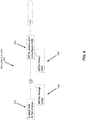
- Figures 4-6 illustrate examples of implementation of the temperature distribution sensors of Figures 1 and 2 , according to an example of the present disclosure.
- an implementation 400 of the sensor 100 may include the laser source 102 (or the first laser source 202 and the second laser source 204) at section 402 of the sensor 100.
- the bandpass filter 108 (or the bandpass filter 210) may be operatively disposed between the laser source 102 and the DUT 104, and may be configured to an anti-Stokes wavelength that is narrower than the Raman bandwidth.
- the photodiode 110 (or the photodiode 212), designated as an avalanche photodiode (APD), may be operatively disposed between the bandpass filter 108 and the DUT 104 to acquire, from the DUT 104, anti-Stokes optical time-domain reflectometer traces for two preset wavelengths of the laser beam to determine the temperature distribution 112 for the DUT 104.
- the further photodiode 114 (or the further photodiode 216) may be operatively disposed between the laser source 102 and the bandpass filter 108 to acquire Rayleigh optical time-domain reflectometer traces at the two preset wavelengths of the laser beam.
- a tunable laser and a fixed bandpass filter may be utilized.
- an implementation 500 of the sensor 100 may include the laser source 102 (or the first laser source 202 and the second laser source 204) at section 502 of the sensor 100.
- the bandpass filter 108 (or the bandpass filter 210) may be operatively disposed between the laser source 102 and the DUT 104, and may be configured to an anti-Stokes wavelength that is narrower than the Raman bandwidth.
- a single photodiode 110 (or the photodiode 212) may be operatively connected to a switch at section 508 of the sensor 100.
- the switch at section 508 of the sensor 100 may be operated so that the photodiode 110 (or the photodiode 212) is operatively disposed between the bandpass filter 108 and the DUT 104 to acquire, from the DUT 104, anti-Stokes optical time-domain reflectometer traces for two preset wavelengths of the laser beam to determine the temperature distribution 112 for the DUT 104. Further, the switch at section 508 of the sensor 100 may be operated so that the photodiode 110 (or the photodiode 212) is operatively disposed between the laser source 102 and the bandpass filter 108 to acquire Rayleigh optical time-domain reflectometer traces at the two preset wavelengths of the laser beam.
- an implementation 600 of the sensor 100 may include the laser source 102 at section 602 of the sensor 100.
- Laser pulses may be sent to the DUT.
- backscattered radiation may be directed towards bandpass filters linked via wavelength division multiplexing (WDM) to successively record the anti-Stokes Raman OTDR trace at two optical frequencies.
- WDM wavelength division multiplexing
- the switch and fixed filters may be replaced by a tunable filter.
- a differential attenuation between the two preset wavelengths of the laser beam may be corrected by determining a ratio of the Rayleigh optical time-domain reflectometer traces at the two preset wavelengths of the laser beam.
- a tunable laser e.g., 40nm at 1550nm
- a fixed bandpass filter implemented as shown in Figures 4 and 5 may be utilized.
- the two backward Raman wavelength losses may be virtually identical as they are selected by the same bandpass filter.
- the losses at forward pulse wavelengths e.g., forward losses
- the loss in sensitivity to temperature may be equivalent to a loss of dynamic range, for example, by 2.6dB. This value may represent a default value.
- the optics of the implementation may allow to spare approximately 1.4dB of dynamic range (e.g., 5 LOG).
- a wavelength difference resulting from differing anti-Stokes spectral slices and a corresponding mean weighted average wavelength may be corrected.
- a relatively small difference of a few nm may remain in the mean-weighted-average anti-Stokes wavelength due to the Raman spectral shape.
- Figure 7 illustrates a 30nm bandpass filtered anti-stokes Raman spectra with test wavelengths at min-max of Erbium/C-band, according to an example of the present disclosure.
- this aspect may be evaluated in the graphic of Figure 7 of the expected filtered spectra with two test wavelengths, for example, at 1529 and 1569nm, and a bandpass of 30nm.
- these curves may represent the two Raman spectra of backscattered radiation that is obtained when sending laser light at 1529 and 1569nm, respectively.
- the spectra for the example of Figure 7 may be windowed by the bandpass rectangular profile.
- the test wavelengths may be at the extremes of the C-band of fiber telecommunications, where sources and erbium doped fibers may be utilized.
- scaling may be based on the width of bandpass (e.g., 3nm for a 30nm bandwidth for the following example), so that the difference may be reduced, at the cost of a lower signal power and therefore a lower dynamic range.
- a differential loss may be extrapolated at those latter wavelengths to produce a further correction on the fiber losses.
- Reducing the bandwidth of the Stokes band by use of a bandpass filter may provide for the reduction of the chromatic dispersion induced spatial spread and associated loss of spatial resolution, for example, in monomode fiber applications.
- multimode applications may be primarily affected by modal dispersion.
- Figure 8 illustrates a table of various consequences of bandpass filter width, as a guideline for the determination of an optimal value, according to an example of the present disclosure.
- a lower bandwidth may improve the wavelength definition (remaining differential loss problem) and the potential to reach longer distances while maintaining spatial resolution (CD problem). Further, a larger bandwidth may be utilized to maintain the dynamic range of an instrument (e.g., proportionally higher power).
- the columns of Figure 8 may include bandpass filter width (nm), lambda error (nm), spread due to backward chromatic dispersion (CD) at 30 km (m), sensitivity, power, losses, and bill.
- the two anti-Stokes powers at the two spectral slices may follow Bose-Einstein statistics as follows: I AS T ⁇ ⁇ 1 , 2 ⁇ 1 exp h ⁇ ⁇ 1 , 2 kT ⁇ 1
- I AS represents the intensity detected
- T represents the temperature
- ⁇ ⁇ 1,2 represents the mean-weighted average frequency shift for the anti-Stokes spectral slice considered
- h represents the Planck's constant
- k represents the Boltzmann constant.
- the temperature distribution 112 (or the temperature distribution 214) for the DUT may be determined by determining a ratio of the anti-Stokes optical time-domain reflectometer traces for the two preset wavelengths of the laser beam.
- the ratio of the two Stokes may be derived from OTDR traces for every point of the link.
- the ratio may be normalized to the ratio measured in a reference section at a known temperature T 0 as follows (this may provide for elimination of the constants of proportionality disregarded in Equation (4)):
- R represents the anti-Stokes to Stokes ratio
- ⁇ ⁇ 1 represents the mean-weighted average frequency shift for spectral slice 1
- ⁇ ⁇ 2 represents the mean-weighted average frequency shift for spectral slice 2.
- Equation (5) may be solved numerically to derive T all along the fiber from a measured ratio.
- the temperature distribution sensor 100 as disclosed herein may include a single source or a single-band solution.
- the temperature distribution sensor 100 may include a relatively small tuning range or dual source, 20nm broad/apart at 1064nm, 40nm broad/apart at 1550nm.
- the temperature distribution sensor 100 as disclosed herein may include a single source as disclosed herein.
- C-Band components at 1550nm, C-Band components, fiber lasers, and fiber amplifiers based on Erbium dopant may be utilized.
- fiber lasers at 1550nm, C-Band components, fiber lasers, and fiber amplifiers based on Erbium dopant may be utilized.
- fiber amplifiers based on Erbium dopant may be utilized.
- Y-Band components and their capacity at producing 1040-1068nm light may be utilized.
- the temperature distribution sensor 100 as disclosed herein may provide for compensation of differential slope (e.g., with bending or bleaching). This may be associated with the same wavelength band in the anti-Stokes range (e.g., a power slope within band which create differing mean wavelengths anti-Stokes-1 (AS1) and anti-Stokes-2 (AS2), and two different probe wavelengths (e.g., 40nm compared to the 100nm of the dual-laser solution of Figure 2 ). Differential fiber losses may be measured in Rayleigh mode at these two test probe wavelengths.
- differential slope e.g., with bending or bleaching
- the four slopes may provide for the quantification of the whole link (e.g., Rayleigh 1 (lambda 1 forward and lambda 1 backward), Rayleigh 2 (lambda 2 forward and lambda 2 backward), AS1 (lambda 1 forward and AS1 backward) and AS2 (lambda 2 forward and AS2 backward).
- Rayleigh 1 (lambda 1 forward and lambda 1 backward)
- Rayleigh 2 (lambda 2 forward and lambda 2 backward)
- AS1 laambda 1 forward and AS1 backward
- AS2 laambda 2 forward and AS2 backward
- the temperature distribution sensor 100 as disclosed herein may provide for a single-ended test for temperature distribution.
- the temperature distribution sensor 100 as disclosed herein may eliminate the need for a dual-ended test, which may include installation constraints which may not be possible to implement.
- the temperature distribution sensor 100 as disclosed herein may provide for an intrinsic tolerance to nonlinearity.
- the two test probes and backscattered signals may be considered as equal with regard to non-linearity given the very similar wavelengths, power levels, and fiber attenuation profiles.
- the nonlinearity may affect each measure differently (e.g., Anti-Stokes retrofitting energy to forward pulse, Rayleigh depleted by co-propagating forward Stokes pulses, Stokes band increased by Rayleigh scattering of the same forward Stokes pulse, etc.).
- the laser source may include a narrow linewidth tunable laser.
- the sensor 100 may be operated using the narrow linewidth tunable laser source in a Rayleigh mode to record a distributed acoustic sensing signal over the DUT.
- use of a narrow linewidth laser may provide for compatibility with a distributed acoustic sensing option.
- the Rayleigh section of the new distributed temperature sensing scheme previously described may include a direct-detection acquisition line that is also compatible with an intensity based distributed acoustic sensing.
- a coherent detection scheme may provide a suitable mean for the differential slope compensations at source wavelengths, while also providing a higher sensitivity for an intelligent distributed acoustic sensor and the potential for a Phase-distributed acoustic sensing analysis.
- a distributed temperature sensing and a distributed acoustic sensing interrogator may be used alternatively and even simultaneously on the same sensing fiber with added value when crossing the respective information for these interrogators.
- Disposal of a tunable laser in the distributed acoustic sensing application with respect to wavelength diversity may provide for the reduction of the fading of the sensor response at locations of destructive interferences.
- the narrow linewidth laser and narrow-filtered Raman signal may reduce the chromatic dispersion effect, which may limit the spatial resolution in long-distance monomode applications.
- the temperature distribution sensor 100 as disclosed herein may be applicable to multimode applications.
- the temperature distribution sensor 100 may require limited tunability (e.g., 20nm @1064nm) and a narrower bandpass.
- a narrow bandpass filter may be used for the purpose of reducing the chromatic-dispersion-related loss of spatial resolution. This loss may be overcome with relatively large pulse power, and a higher power compared to all existing solutions that are affected by nonlinearity issues.
- the temperature distribution sensor 100 as disclosed herein may include a fiber amplifier and utilize larger peak powers than otherwise possible, which may result in a net gain on the dynamic range.
- Figure 9 shows a computer system 900 that may be used with the examples described herein.
- the computer system may represent a generic platform that includes components that may be in a server or another computer system.
- the computer system 900 may be used as part of a platform for the sensor controller of Figure 1 and/or Figure 2 .
- the computer system 900 may execute, by a processor (e.g., a single or multiple processors) or other hardware processing circuit, the methods, functions and other processes described herein.
- a processor e.g., a single or multiple processors
- a computer readable medium which may be non-transitory, such as hardware storage devices (e.g., RAM (random access memory), ROM (read only memory), EPROM (erasable, programmable ROM), EEPROM (electrically erasable, programmable ROM), hard drives, and flash memory).
- RAM random access memory
- ROM read only memory
- EPROM erasable, programmable ROM
- EEPROM electrically erasable, programmable ROM
- hard drives e.g., hard drives, and flash memory
- the computer system 900 may include a processor 902 that may implement or execute machine readable instructions performing some or all of the methods, functions and other processes described herein. Commands and data from the processor 902 may be communicated over a communication bus 904.
- the computer system may also include a main memory 906, such as a random access memory (RAM), where the machine readable instructions and data for the processor 902 may reside during runtime, and a secondary data storage 908, which may be non-volatile and stores machine readable instructions and data.
- the memory and data storage are examples of computer readable mediums.
- the memory 906 may include the sensor controller of Figure 1 and/or Figure 2 including machine readable instructions residing in the memory 906 during runtime and executed by the processor 902.
- the computer system 900 may include an I/O device 910, such as a keyboard, a mouse, a display, etc.
- the computer system may include a network interface 912 for connecting to a network.
- Other known electronic components may be added or substituted in the computer system.
- the processor 902 may be designated as a hardware processor.
- the processor 902 may execute operations associated with various components of the sensor 100.
- the processor 902 may execute operations associated with the sensor controller of Figure 1 and/or Figure 2 , etc.
Abstract
Description
- Distributed temperature sensing may be described as the measurement of temperature by using optical fibers. In distributed temperature sensing, an optical fiber may function as a sensor. A distributed temperature sensing system may provide temperature measurements at specified distances along the length of the optical fiber. For example, the specified distances may include a spatial resolution of one meter. The temperature measurements may be made to a specified accuracy (e.g., ± 0.5°C).
- According to a first aspect, there is provided a temperature distribution sensor comprising a laser source to emit a laser beam that is tunable over a wavelength range, wherein the wavelength range is less than a Raman bandwidth in a device under test (DUT), or of-the-order-of the Raman bandwidth in the DUT; a pulsed source to apply a pulse drive signal to the laser beam or to a modulator to modulate the laser beam that is to be injected into the DUT; a bandpass filter that is operatively disposed between the laser source and the DUT, wherein the bandpass filter is configured to an anti-Stokes wavelength that is narrower than the Raman bandwidth; and a photodiode that is operatively disposed between the bandpass filter and the DUT to acquire, from the DUT, anti-Stokes optical time-domain reflectometer traces for two preset wavelengths of the laser beam to determine a temperature distribution for the DUT.
- The DUT may include an optical fiber.
- The temperature distribution sensor may further comprise: a fiber amplifier to amplify the pulse drive signal applied to the laser beam or to the modulator to modulate the laser beam that is to be injected into the DUT.
- The temperature distribution sensor may further comprise: a further photodiode operatively disposed between the laser source and the bandpass filter to acquire Rayleigh optical time-domain reflectometer traces at the two preset wavelengths of the laser beam.
- The temperature distribution sensor may further comprise: a processor; and a memory storing machine readable instructions that when executed by the processor cause the processor to: correct a differential attenuation between the two preset wavelengths of the laser beam by determining a ratio of the Rayleigh optical time-domain reflectometer traces at the two preset wavelengths of the laser beam.
- The temperature distribution sensor may further comprise: a processor; and a memory storing machine readable instructions that when executed by the processor cause the processor to: determine the temperature distribution for the DUT by determining a ratio of the anti-Stokes optical time-domain reflectometer traces for the two preset wavelengths of the laser beam.
- The temperature distribution sensor may further comprise: a processor; and a memory storing machine readable instructions that when executed by the processor cause the processor to: correct, for the anti-Stokes optical time-domain reflectometer traces for the two preset wavelengths of the laser beam, a wavelength difference resulting from differing anti-Stokes spectral slices and a corresponding mean weighted average wavelength.
- The temperature distribution sensor, wherein the laser may be a narrow linewidth tunable laser, may further comprise: a processor; and a memory storing machine readable instructions that when executed by the processor cause the processor to: operating, using the narrow linewidth tunable laser source, in a Rayleigh mode to record a distributed acoustic sensing signal over the DUT.
- According to a second aspect, there is provided a temperature distribution sensor comprising: a first laser source to emit a first laser beam; a second laser source to emit a second laser beam, wherein the first and second laser beams include wavelengths that differ by a quantity that is less than a Raman bandwidth in a device under test (DUT), or of-the-order-of the Raman bandwidth in the DUT; a pulsed source to apply a pulse drive signal to the first and second laser beams or to a modulator to modulate the first and second laser beams that are to be injected into the DUT; a bandpass filter that is operatively disposed between the first and second laser sources and the DUT, wherein the bandpass filter is configured to an anti-Stokes wavelength that is narrower than the Raman bandwidth; and a photodiode that is operatively disposed between the bandpass filter and the DUT to acquire, from the DUT, anti-Stokes optical time-domain reflectometer traces for two preset wavelengths of the first and second laser beams to determine a temperature distribution for the DUT.
- The DUT may include an optical fiber.
- The temperature distribution may further comprise: a fiber amplifier to amplify the pulse drive signal applied to the first and second laser beams or to the modulator to modulate the first and second laser beams that are to be injected into the DUT.
- The temperature distribution may further comprise: a further photodiode operatively disposed between the first and second laser sources and the bandpass filter to acquire Rayleigh optical time-domain reflectometer traces at the two preset wavelengths of the first and second laser beams.
- The temperature distribution may further comprise: a processor; and a memory storing machine readable instructions that when executed by the processor cause the processor to: correct a differential attenuation between the two preset wavelengths of the first and second laser beams by determining a ratio of the Rayleigh optical time-domain reflectometer traces at the two preset wavelengths of the first and second laser beams.
- The temperature distribution may further comprise: a processor; and a memory storing machine readable instructions that when executed by the processor cause the processor to: determine the temperature distribution for the DUT by determining a ratio of the anti-Stokes optical time-domain reflectometer traces for the two preset wavelengths of the first and second laser beams.
- The temperature distribution may further comprise: a processor; and a memory storing machine readable instructions that when executed by the processor cause the processor to: correct, for the anti-Stokes optical time-domain reflectometer traces for the two preset wavelengths of the first and second laser beams, a wavelength difference resulting from differing anti-Stokes spectral slices and a corresponding mean weighted average wavelength.
- The temperature distribution, wherein the first or second laser source may be a narrow linewidth tunable laser, may further comprise: a processor; and a memory storing machine readable instructions that when executed by the processor cause the processor to: operating, using the narrow linewidth tunable laser source, in a Rayleigh mode to record a distributed acoustic sensing signal over the DUT.
- According to a third aspect, there is provided a computer implemented method comprising: emitting, from a laser source, a laser beam that is tunable over a wavelength range, wherein the wavelength range is less than a Raman bandwidth in a device under test (DUT), or of-the-order-of the Raman bandwidth in the DUT; applying a pulse drive signal to the laser beam or to a modulator to modulate the laser beam that is to be injected into the DUT; configuring a bandpass filter that is operatively disposed between the laser source and the DUT to an anti-Stokes wavelength that is narrower than the Raman bandwidth; and
determining a temperature distribution for the DUT by acquiring, from the DUT, anti-Stokes optical time-domain reflectometer traces for two preset wavelengths of the laser beam. - The DUT may include an optical fiber.
- The method may further comprise: acquiring Rayleigh optical time-domain reflectometer traces at the two preset wavelengths of the laser beam; and correcting a differential attenuation between the two preset wavelengths of the laser beam by determining a ratio of the Rayleigh optical time-domain reflectometer traces at the two preset wavelengths of the laser beam.
- The method, wherein determining the temperature distribution for the DUT may acquire, from the DUT, the anti-Stokes optical time-domain reflectometer traces for the two preset wavelengths of the laser beam, may further comprise: determining the temperature distribution for the DUT by determining a ratio of the anti-Stokes optical time-domain reflectometer traces for the two preset wavelengths of the laser beam.
- Features of the present disclosure are illustrated by way of examples shown in the following figures. In the following figures, like numerals indicate like elements, in which:
-
Figure 1 illustrates an architecture of a temperature distribution sensor, according to an example of the present disclosure; -
Figure 2 illustrates an architecture of the temperature distribution sensor, according to another example of the present disclosure; -
Figure 3 illustrates the sensitivity as a function of wavelength, when a device under test is illuminated at 1550nm, according to an example of the present disclosure; -
Figures 4-6 illustrate examples of implementation of the temperature distribution sensors ofFigures 1 and2 , according to an example of the present disclosure; -
Figure 7 illustrates a 30nm bandpass filtered anti-stokes Raman spectra with test wavelengths at min-max of Erbium/C-band, according to an example of the present disclosure; -
Figure 8 illustrates a table of various consequences of bandpass filter width, as a guideline for the determination of an optimal value, according to an example of the present disclosure; and -
Figure 9 illustrates a computer system, according to an example of the present disclosure. - For simplicity and illustrative purposes, the present disclosure is described by referring mainly to examples thereof. In the following description, details are set forth in order to provide an understanding of the present disclosure. It will be readily apparent however, that the present disclosure may be practiced without limitation to these details. In other instances, some methods and structures have not been described in detail so as not to unnecessarily obscure the present disclosure.
- Throughout the present disclosure, the terms "a" and "an" are intended to denote at least one of a particular element. As used herein, the term "includes" means includes but not limited to, the term "including" means including but not limited to. The term "based on" means based at least in part on.
- An optical time-domain reflectometer (OTDR) is an optoelectronic instrument used to characterize an optical fiber. The OTDR may inject a series of optical pulses into an optical fiber under test. Based on the injected optical pulses, the OTDR may extract, from the same end of the optical fiber in which the optical pulses are injected, light that is scattered or reflected back from points along the optical fiber. The scattered or reflected light that is gathered back may be used to characterize the optical fiber. For example, the scattered or reflected light that is gathered back may be used to detect, locate, and measure events at any location of the optical fiber. The events may include faults at any location of the optical fiber. Other types of features that may be measured by the OTDR include temperature distribution along a fiber, attenuation uniformity and attenuation rate, segment length, and location and insertion loss of connectors, splices, or any other optical components such as splitters or multiplexers.
- With respect to temperature distribution measurement by an OTDR, an OTDR may include distributed temperature sensing (DTS). For DTS, Raman distributed temperature sensing may encounter different attenuations at different test wavelengths. For example, the different test wavelengths may include the Anti-Stokes (AS) wavelength, the Rayleigh wavelength, the Stokes wavelength, etc. In order to implement distributed temperature sensing, interrogation of an optical fiber may be performed by using several laser sources. Alternatively or additionally, the interrogation of the optical fiber may be dual-ended (e.g., on both ends of the optical fiber). For an interrogation that includes several laser sources, the distributed temperature sensing results may include inconsistencies in that differing spectral shapes of the various test signals used may result in different mean-weighted-average wavelengths and non-matching attenuation compensations. For an interrogation that is dual-ended, the need to access both ends of an optical fiber may add additional technical complexities, for example, with respect to a downhole end of the optical fiber.
- Distributed temperature sensing may utilize the temperature sensitivity of an anti-Stokes Raman band in order to derive temperature. Since the transient Raman OTDR signal may also decay with attenuation, the signal may be normalized to the Stokes-OTDR trace. In this regard, a Rayleigh OTDR trace may also be utilized.
- In order address the aforementioned technical challenges, a temperature distribution sensor as disclosed herein may utilize two spectral slices of the Anti-Stokes Raman to implement distributed temperature sensing. In this regard, the coefficient of the Anti-Stokes power variation versus temperature depends on the exact wavelength. As disclosed herein, this dependency may be evident from the literal equation of the anti-Stokes power derived from Bose-Einstein statistics. Further, the differential response at closely spaced wavelengths may be utilized as a new mechanism in distributed temperature sensing, with an inherently reduced differential loss, while also offering new means for differential losses compensation.
-
Figure 1 illustrates an architecture of a temperature distribution sensor 100 (hereinafter referred to as "sensor 100"), according to an example of the present disclosure. - Referring to
Figure 1 , thesensor 100, which may be an OTDR, may include alaser source 102 to emit a laser beam that is tunable over a wavelength range. The wavelength range may be less than a Raman bandwidth in a device under test (DUT) 104, or of-the-order-of the Raman bandwidth in theDUT 104. According to examples, theDUT 104 may include an optical fiber. - A
pulsed source 106 may apply a pulse drive signal to the laser beam or to a modulator to modulate the laser beam that is to be injected into theDUT 104. - A
bandpass filter 108 may be operatively disposed between thelaser source 102 and theDUT 104. Thebandpass filter 108 may be configured to an anti-Stokes wavelength that is narrower than the Raman bandwidth. - A
photodiode 110 may be operatively disposed between thebandpass filter 108 and theDUT 104 to acquire, from theDUT 104, anti-Stokes optical time-domain reflectometer traces for two preset wavelengths of the laser beam to determine (e.g., by a sensor controller) atemperature distribution 112 for theDUT 104. In this regard, thetemperature distribution 112 for theDUT 104 may be determined by determining a ratio of the anti-Stokes optical time-domain reflectometer traces for the two preset wavelengths of the laser beam. Further, with respect to the anti-Stokes optical time-domain reflectometer traces for the two preset wavelengths of the laser beam, a wavelength difference resulting from differing anti-Stokes spectral slices and a corresponding mean weighted average wavelength may be corrected. - A
further photodiode 114 may be operatively disposed between thelaser source 102 and thebandpass filter 108 to acquire Rayleigh optical time-domain reflectometer traces at the two preset wavelengths of the laser beam. In this regard, a differential attenuation between the two preset wavelengths of the laser beam may be corrected by determining a ratio of the Rayleigh optical time-domain reflectometer traces at the two preset wavelengths of the laser beam. - A
fiber amplifier 116 may amplify the pulse drive signal applied to the laser beam or to the modulator to modulate the laser beam that is to be injected into theDUT 104. Theamplifier 116 may comprise a temporal gating element that may suppress the amplified spontaneous emission and associated power fluctuations in between pulses. - According to examples, for the
laser source 102 that includes a narrow linewidth tunable laser, thesensor 100 may be operated, using the narrow linewidth tunable laser source, in a Rayleigh mode to record a distributed acoustic sensing signal over theDUT 104. - Referring to
Figure 2 , an example of thesensor 100 that includes two laser sources may be designated assensor 200. In this regard, thesensor 200, which may be an OTDR, may include afirst laser source 202 to emit a first laser beam, and asecond laser source 204 to emit a second laser beam. The first and second laser beams may include wavelengths that differ by a quantity that is less than a Raman bandwidth in aDUT 206, or of-the-order-of the Raman bandwidth in theDUT 206. - A
pulsed source 208 may apply a pulse drive signal to the first and second laser beams or to a modulator to modulate the first and second laser beams that are to be injected into theDUT 206. - A
bandpass filter 210 may be operatively disposed between thefirst laser source 202 and thesecond laser source 204 and theDUT 206. Thebandpass filter 210 may be configured to an anti-Stokes wavelength that is narrower than the Raman bandwidth. - A
photodiode 212 may be operatively disposed between thebandpass filter 210 and theDUT 206 to acquire, from theDUT 206, anti-Stokes optical time-domain reflectometer traces for two preset wavelengths of the first and second laser beams to determine atemperature distribution 214 for theDUT 206. Thephotodiode 212 may be connected to the passing port of thebandpass filter 210. Thefirst laser source 202 and thesecond laser source 204 may be connected to the reflective port of the bandpass filter 210 (complementary of the passband function), and theDUT 206 to the common port of thebandpass filter 210. - A
further photodiode 216 may be operatively disposed between thefirst laser source 202 and thesecond laser source 204 and thebandpass filter 210 to acquire Rayleigh optical time-domain reflectometer traces at the two pre-set wavelengths of the first and second laser beams. - Operation of the sensor 100 (and the sensor 200) is described in further detail with reference to
Figures 3-8 . - As disclosed herein, the sensor 100 (and the sensor 200) may utilize two spectral slices of the Anti-Stokes Raman to implement distributed temperature sensing. In this regard, the coefficient of the Anti-Stokes power variation versus temperature may depend on the exact wavelength. This dependency may be evident from the literal expression of the number of optical phonons η generated by thermal agitation and derived from Bose-Einstein statistics.


- As disclosed herein, the spectral dependency of the phonon population within a single Raman anti-Stokes band may be utilized as the core mechanism for sensing. From Equation (1), the coefficient of variation of the Raman anti-Stokes power with temperature, as a function of frequency, may be determined. This coefficient may represent the derivative of the population with temperature, normalized to the population itself in order to express a sensitivity in %/K for Raman sensing, and may be expressed as follows:

-
Figure 3 illustrates the sensitivity as a function of wavelength, when the DUT is illuminated at 1550nm, according to an example of the present disclosure. The sensitivity may vary substantially across the useful range of the Raman profile. The mean value of 0.8%/K may be found at Raman resonance of 1450nm, but sensitivity may vary from 0.95 to 0.72%/K for spectral components of 1430 to 1470nm respectively. Thus, instead of making the ratio of the anti-Stokes to the Stokes and obtaining a final sensitivity of approximately 0.7%/K, by taking the ratio of two spectral components of the anti-Stokes which are 40nm apart, a 0.23%/K sensitivity may be expected. This lower sensitivity value may increase the sensitivity to detection noises and lower the dynamic range. However, as will be described hereafter, several key advantages arise from the use of a reduced spectral range (e.g., 40nm instead of 200nm at 1550nm). -
Figures 4-6 illustrate examples of implementation of the temperature distribution sensors ofFigures 1 and2 , according to an example of the present disclosure. - Referring to
Figure 4 , animplementation 400 of the sensor 100 (or the sensor 200) may include the laser source 102 (or thefirst laser source 202 and the second laser source 204) atsection 402 of thesensor 100. Atsection 404 of thesensor 100, the bandpass filter 108 (or the bandpass filter 210) may be operatively disposed between thelaser source 102 and theDUT 104, and may be configured to an anti-Stokes wavelength that is narrower than the Raman bandwidth. Atsection 406 of thesensor 100, the photodiode 110 (or the photodiode 212), designated as an avalanche photodiode (APD), may be operatively disposed between thebandpass filter 108 and theDUT 104 to acquire, from theDUT 104, anti-Stokes optical time-domain reflectometer traces for two preset wavelengths of the laser beam to determine thetemperature distribution 112 for theDUT 104. Atsection 408 of thesensor 100, the further photodiode 114 (or the further photodiode 216) may be operatively disposed between thelaser source 102 and thebandpass filter 108 to acquire Rayleigh optical time-domain reflectometer traces at the two preset wavelengths of the laser beam. - Referring to
Figure 5 , a tunable laser and a fixed bandpass filter may be utilized. - Referring to
Figure 5 , animplementation 500 of the sensor 100 (or the sensor 200) may include the laser source 102 (or thefirst laser source 202 and the second laser source 204) atsection 502 of thesensor 100. Atsection 504 of thesensor 100, the bandpass filter 108 (or the bandpass filter 210) may be operatively disposed between thelaser source 102 and theDUT 104, and may be configured to an anti-Stokes wavelength that is narrower than the Raman bandwidth. Atsection 506 of thesensor 100, a single photodiode 110 (or the photodiode 212) may be operatively connected to a switch atsection 508 of thesensor 100. In this regard, the switch atsection 508 of thesensor 100 may be operated so that the photodiode 110 (or the photodiode 212) is operatively disposed between thebandpass filter 108 and theDUT 104 to acquire, from theDUT 104, anti-Stokes optical time-domain reflectometer traces for two preset wavelengths of the laser beam to determine thetemperature distribution 112 for theDUT 104. Further, the switch atsection 508 of thesensor 100 may be operated so that the photodiode 110 (or the photodiode 212) is operatively disposed between thelaser source 102 and thebandpass filter 108 to acquire Rayleigh optical time-domain reflectometer traces at the two preset wavelengths of the laser beam. - Referring to
Figure 6 , animplementation 600 of thesensor 100 may include thelaser source 102 atsection 602 of thesensor 100. Laser pulses may be sent to the DUT. Atsection 604 of thesensor 100, backscattered radiation may be directed towards bandpass filters linked via wavelength division multiplexing (WDM) to successively record the anti-Stokes Raman OTDR trace at two optical frequencies. Alternatively, the switch and fixed filters may be replaced by a tunable filter. With respect to the aspect of "Lambda laser minus (Raman Shift - Δλ)" versus "Lambda laser minus (Raman Shift + Δλ)", in this implementation where two bandpass filters would be used, for an example with a single laser at 1550nm, the Raman shift is -100nm, and for the anti-Stokes at 1450, there may be a bandpass at 1450-15 and a bandpass at 1450+15nm. - As disclosed herein, a differential attenuation between the two preset wavelengths of the laser beam may be corrected by determining a ratio of the Rayleigh optical time-domain reflectometer traces at the two preset wavelengths of the laser beam. In this regard, in case of a high differential loss profile, it may be technically challenging to measure and account for the differential attenuation between the two anti-Stokes wavelengths, irrespective of how closely spaced they the anti-Stokes wavelengths are. In this regard, a tunable laser (e.g., 40nm at 1550nm) and a fixed bandpass filter, implemented as shown in
Figures 4 and5 may be utilized. With respect toFigures 4 and5 , the two backward Raman wavelength losses may be virtually identical as they are selected by the same bandpass filter. The losses at forward pulse wavelengths (e.g., forward losses), may now be different, and may be measured in the Rayleigh OTDR mode. - For a nominal case where the two test wavelengths are separated by approximately the Raman bandwidth, the loss in sensitivity to temperature may be equivalent to a loss of dynamic range, for example, by 2.6dB. This value may represent a default value. However, compared to a dual wavelength setup, the optics of the implementation may allow to spare approximately 1.4dB of dynamic range (e.g., 5 LOG).
- As disclosed herein, with respect to the anti-Stokes optical time-domain reflectometer traces for the two preset wavelengths of the laser beam, a wavelength difference resulting from differing anti-Stokes spectral slices and a corresponding mean weighted average wavelength may be corrected. In this regard, a relatively small difference of a few nm may remain in the mean-weighted-average anti-Stokes wavelength due to the Raman spectral shape. In this regard,
Figure 7 illustrates a 30nm bandpass filtered anti-stokes Raman spectra with test wavelengths at min-max of Erbium/C-band, according to an example of the present disclosure. Referring toFigure 7 , with respect to the relatively small difference of a few nm that may remain in the mean-weighted-average anti-Stokes wavelength, this aspect may be evaluated in the graphic ofFigure 7 of the expected filtered spectra with two test wavelengths, for example, at 1529 and 1569nm, and a bandpass of 30nm. With respect to the two curves at 700 and 702, these curves may represent the two Raman spectra of backscattered radiation that is obtained when sending laser light at 1529 and 1569nm, respectively. The spectra for the example ofFigure 7 may be windowed by the bandpass rectangular profile. The test wavelengths may be at the extremes of the C-band of fiber telecommunications, where sources and erbium doped fibers may be utilized. In order to mitigate any issues pertaining to the relatively small difference, scaling may be based on the width of bandpass (e.g., 3nm for a 30nm bandwidth for the following example), so that the difference may be reduced, at the cost of a lower signal power and therefore a lower dynamic range. Secondly from the knowledge of the origin of the losses (e.g., bending or darkening), the knowledge of the fiber attenuation at the two precisely defined laser wavelengths, and the knowledge of the test wavelengths including the two calibrated mean-weighted average anti-Stokes wavelengths, a differential loss may be extrapolated at those latter wavelengths to produce a further correction on the fiber losses. - Reducing the bandwidth of the Stokes band by use of a bandpass filter may provide for the reduction of the chromatic dispersion induced spatial spread and associated loss of spatial resolution, for example, in monomode fiber applications. In this regard, multimode applications may be primarily affected by modal dispersion.
-
Figure 8 illustrates a table of various consequences of bandpass filter width, as a guideline for the determination of an optimal value, according to an example of the present disclosure. - Referring to the table 800 of
Figure 8 , a lower bandwidth may improve the wavelength definition (remaining differential loss problem) and the potential to reach longer distances while maintaining spatial resolution (CD problem). Further, a larger bandwidth may be utilized to maintain the dynamic range of an instrument (e.g., proportionally higher power). The columns ofFigure 8 may include bandpass filter width (nm), lambda error (nm), spread due to backward chromatic dispersion (CD) at 30 km (m), sensitivity, power, losses, and bill. For the table 800, bill may represent the sum of the various contributions to dynamic range (e.g., for row 1, 2.6 + 4.4 - 1.4 = 5.6dB). With respect to the CD impact, the delay corresponding to the two extremes of the bandpass may be determined, for example, using 10ps/nm/km at 1450nm and 10ns/m correspondence on an OTDR curve. For example, for row 1, 10ps/nm/km x 30km x 10nm / 10ns/m=0.3m. - In order to recover the temperature information, the two anti-Stokes powers at the two spectral slices, centered at Δϑ1 and Δϑ2 respectively, may follow Bose-Einstein statistics as follows:

- As disclosed herein, the temperature distribution 112 (or the temperature distribution 214) for the DUT may be determined by determining a ratio of the anti-Stokes optical time-domain reflectometer traces for the two preset wavelengths of the laser beam. The ratio of the two Stokes may be derived from OTDR traces for every point of the link. Further, the ratio may be normalized to the ratio measured in a reference section at a known temperature T 0 as follows (this may provide for elimination of the constants of proportionality disregarded in Equation (4)):

spectral slice 2. Equation (5) may be solved numerically to derive T all along the fiber from a measured ratio. - The
temperature distribution sensor 100 as disclosed herein may include a single source or a single-band solution. In this regard, thetemperature distribution sensor 100 may include a relatively small tuning range or dual source, 20nm broad/apart at 1064nm, 40nm broad/apart at 1550nm. - The
temperature distribution sensor 100 as disclosed herein may include a single source as disclosed herein. In this regard, at 1550nm, C-Band components, fiber lasers, and fiber amplifiers based on Erbium dopant may be utilized. At 1064nm, for example, Y-Band components and their capacity at producing 1040-1068nm light may be utilized. - The
temperature distribution sensor 100 as disclosed herein may provide for compensation of differential slope (e.g., with bending or bleaching). This may be associated with the same wavelength band in the anti-Stokes range (e.g., a power slope within band which create differing mean wavelengths anti-Stokes-1 (AS1) and anti-Stokes-2 (AS2), and two different probe wavelengths (e.g., 40nm compared to the 100nm of the dual-laser solution ofFigure 2 ). Differential fiber losses may be measured in Rayleigh mode at these two test probe wavelengths. The four slopes may provide for the quantification of the whole link (e.g., Rayleigh 1 (lambda 1 forward and lambda 1 backward), Rayleigh 2 (lambda 2 forward andlambda 2 backward), AS1 (lambda 1 forward and AS1 backward) and AS2 (lambda 2 forward and AS2 backward). - The
temperature distribution sensor 100 as disclosed herein may provide for a single-ended test for temperature distribution. Thus, thetemperature distribution sensor 100 as disclosed herein may eliminate the need for a dual-ended test, which may include installation constraints which may not be possible to implement. - The
temperature distribution sensor 100 as disclosed herein may provide for an intrinsic tolerance to nonlinearity. The two test probes and backscattered signals may be considered as equal with regard to non-linearity given the very similar wavelengths, power levels, and fiber attenuation profiles. In other techniques with dual lasers or three bands, the nonlinearity may affect each measure differently (e.g., Anti-Stokes retrofitting energy to forward pulse, Rayleigh depleted by co-propagating forward Stokes pulses, Stokes band increased by Rayleigh scattering of the same forward Stokes pulse, etc.). - As disclosed herein, for the
temperature distribution sensor 100, the laser source may include a narrow linewidth tunable laser. Thus, thesensor 100 may be operated using the narrow linewidth tunable laser source in a Rayleigh mode to record a distributed acoustic sensing signal over the DUT. In this regard, use of a narrow linewidth laser may provide for compatibility with a distributed acoustic sensing option. The Rayleigh section of the new distributed temperature sensing scheme previously described may include a direct-detection acquisition line that is also compatible with an intensity based distributed acoustic sensing. In this regard, a coherent detection scheme may provide a suitable mean for the differential slope compensations at source wavelengths, while also providing a higher sensitivity for an intelligent distributed acoustic sensor and the potential for a Phase-distributed acoustic sensing analysis. For example, in oil and gas applications, a distributed temperature sensing and a distributed acoustic sensing interrogator may be used alternatively and even simultaneously on the same sensing fiber with added value when crossing the respective information for these interrogators. Disposal of a tunable laser in the distributed acoustic sensing application with respect to wavelength diversity may provide for the reduction of the fading of the sensor response at locations of destructive interferences. - For the
temperature distribution sensor 100 as disclosed herein, the narrow linewidth laser and narrow-filtered Raman signal may reduce the chromatic dispersion effect, which may limit the spatial resolution in long-distance monomode applications. - The
temperature distribution sensor 100 as disclosed herein may be applicable to multimode applications. In this regard, thetemperature distribution sensor 100 may require limited tunability (e.g., 20nm @1064nm) and a narrower bandpass. - For the
temperature distribution sensor 100 as disclosed herein, a narrow bandpass filter may be used for the purpose of reducing the chromatic-dispersion-related loss of spatial resolution. This loss may be overcome with relatively large pulse power, and a higher power compared to all existing solutions that are affected by nonlinearity issues. Thetemperature distribution sensor 100 as disclosed herein may include a fiber amplifier and utilize larger peak powers than otherwise possible, which may result in a net gain on the dynamic range. -
Figure 9 shows acomputer system 900 that may be used with the examples described herein. The computer system may represent a generic platform that includes components that may be in a server or another computer system. Thecomputer system 900 may be used as part of a platform for the sensor controller ofFigure 1 and/orFigure 2 . Thecomputer system 900 may execute, by a processor (e.g., a single or multiple processors) or other hardware processing circuit, the methods, functions and other processes described herein. These methods, functions and other processes may be embodied as machine readable instructions stored on a computer readable medium, which may be non-transitory, such as hardware storage devices (e.g., RAM (random access memory), ROM (read only memory), EPROM (erasable, programmable ROM), EEPROM (electrically erasable, programmable ROM), hard drives, and flash memory). - The
computer system 900 may include aprocessor 902 that may implement or execute machine readable instructions performing some or all of the methods, functions and other processes described herein. Commands and data from theprocessor 902 may be communicated over acommunication bus 904. The computer system may also include amain memory 906, such as a random access memory (RAM), where the machine readable instructions and data for theprocessor 902 may reside during runtime, and asecondary data storage 908, which may be non-volatile and stores machine readable instructions and data. The memory and data storage are examples of computer readable mediums. Thememory 906 may include the sensor controller ofFigure 1 and/orFigure 2 including machine readable instructions residing in thememory 906 during runtime and executed by theprocessor 902. - The
computer system 900 may include an I/O device 910, such as a keyboard, a mouse, a display, etc. The computer system may include anetwork interface 912 for connecting to a network. Other known electronic components may be added or substituted in the computer system. - The
processor 902 may be designated as a hardware processor. Theprocessor 902 may execute operations associated with various components of thesensor 100. For example, theprocessor 902 may execute operations associated with the sensor controller ofFigure 1 and/orFigure 2 , etc. - What has been described and illustrated herein is an example along with some of its variations. The terms, descriptions and figures used herein are set forth by way of illustration only and are not meant as limitations. Many variations are possible within the spirit and scope of the subject matter, which is intended to be defined by the following claims -- and their equivalents -- in which all terms are meant in their broadest reasonable sense unless otherwise indicated.
Claims (15)
- A temperature distribution sensor comprising:a laser source to emit a laser beam that is tunable over a wavelength range, wherein the wavelength range is
less than a Raman bandwidth in a device under test (DUT), or of-the-order-of the Raman bandwidth in the DUT;a pulsed source to apply a pulse drive signal to the laser beam or to a modulator to modulate the laser beam that is to be injected into the DUT;a bandpass filter that is operatively disposed between the laser source and the DUT, wherein the bandpass filter is configured to an anti-Stokes wavelength that is narrower than the Raman bandwidth; anda photodiode that is operatively disposed between the bandpass filter and the DUT to acquire, from the DUT, anti-Stokes optical time-domain reflectometer traces for two preset wavelengths of the laser beam to determine a temperature distribution for the DUT. - The temperature distribution sensor according to claim 1, wherein the DUT includes an optical fiber.
- The temperature distribution sensor according to claim 1, further comprising:
a fiber amplifier to amplify the pulse drive signal applied to the laser beam or to the modulator to modulate the laser beam that is to be injected into the DUT. - The temperature distribution sensor according to claim 1, further comprising:
a further photodiode operatively disposed between the laser source and the bandpass filter to acquire Rayleigh optical time-domain reflectometer traces at the two preset wavelengths of the laser beam. - The temperature distribution sensor according to claim 4, further comprising:a processor; anda memory storing machine readable instructions that when executed by the processor cause the processor to:
correct a differential attenuation between the two preset wavelengths of the laser beam by determining a ratio of the Rayleigh optical time-domain reflectometer traces at the two preset wavelengths of the laser beam. - The temperature distribution sensor according to claim 1, further comprising:a processor; anda memory storing machine readable instructions that when executed by the processor cause the processor to:
determine the temperature distribution for the DUT by determining a ratio of the anti-Stokes optical time-domain reflectometer traces for the two preset wavelengths of the laser beam. - The temperature distribution sensor according to claim 1, further comprising:a processor; anda memory storing machine readable instructions that when executed by the processor cause the processor to:
correct, for the anti-Stokes optical time-domain reflectometer traces for the two preset wavelengths of the laser beam, a wavelength difference resulting from differing anti-Stokes spectral slices and a corresponding mean weighted average wavelength. - The temperature distribution sensor according to claim 1, wherein the laser source is a narrow linewidth tunable laser, further comprising:a processor; anda memory storing machine readable instructions that when executed by the processor cause the processor to:
operating, using the narrow linewidth tunable laser source, in a Rayleigh mode to record a distributed acoustic sensing signal over the DUT. - A temperature distribution sensor comprising:a first laser source to emit a first laser beam;a second laser source to emit a second laser beam, wherein the first and second laser beams include wavelengths that differ by a quantity that is
less than a Raman bandwidth in a device under test (DUT), or of-the-order-of the Raman bandwidth in the DUT;a pulsed source to apply a pulse drive signal to the first and second laser beams or to a modulator to modulate the first and second laser beams that are to be injected into the DUT;a bandpass filter that is operatively disposed between the first and second laser sources and the DUT, wherein the bandpass filter is configured to an anti-Stokes wavelength that is narrower than the Raman bandwidth; anda photodiode that is operatively disposed between the bandpass filter and the DUT to acquire, from the DUT, anti-Stokes optical time-domain reflectometer traces for two preset wavelengths of the first and second laser beams to determine a temperature distribution for the DUT. - The temperature distribution sensor according to claim 9, further comprising:
a further photodiode operatively disposed between the first and second laser sources and the bandpass filter to acquire Rayleigh optical time-domain reflectometer traces at the two preset wavelengths of the first and second laser beams. - The temperature distribution sensor according to claim 10, further comprising:a processor; anda memory storing machine readable instructions that when executed by the processor cause the processor to:
correct a differential attenuation between the two preset wavelengths of the first and second laser beams by determining a ratio of the Rayleigh optical time-domain reflectometer traces at the two preset wavelengths of the first and second laser beams. - The temperature distribution sensor according to claim 9, further comprising:a processor; anda memory storing machine readable instructions that when executed by the processor cause the processor to:
determine the temperature distribution for the DUT by determining a ratio of the anti-Stokes optical time-domain reflectometer traces for the two preset wavelengths of the first and second laser beams. - The temperature distribution sensor according to claim 9, further comprising:a processor; anda memory storing machine readable instructions that when executed by the processor cause the processor to:
correct, for the anti-Stokes optical time-domain reflectometer traces for the two preset wavelengths of the first and second laser beams, a wavelength difference resulting from differing anti-Stokes spectral slices and a corresponding mean weighted average wavelength. - The temperature distribution sensor according to claim 9, wherein the first or second laser source is a narrow linewidth tunable laser, further comprising:a processor; anda memory storing machine readable instructions that when executed by the processor cause the processor to:
operating, using the narrow linewidth tunable laser source, in a Rayleigh mode to record a distributed acoustic sensing signal over the DUT. - A computer implemented method comprising:emitting, from a laser source, a laser beam that is tunable over a wavelength range, wherein the wavelength range is
less than a Raman bandwidth in a device under test (DUT), or of-the-order-of the Raman bandwidth in the DUT;applying a pulse drive signal to the laser beam or to a modulator to modulate the laser beam that is to be injected into the DUT;configuring a bandpass filter that is operatively disposed between the laser source and the DUT to an anti-Stokes wavelength that is narrower than the Raman bandwidth; anddetermining a temperature distribution for the DUT by acquiring, from the DUT, anti-Stokes optical time-domain reflectometer traces for two preset wavelengths of the laser beam.
Priority Applications (1)
| Application Number | Priority Date | Filing Date | Title |
|---|---|---|---|
| EP23183139.7A EP4239300A3 (en) | 2018-03-09 | 2019-01-29 | Single-band distributed temperature sensing |
Applications Claiming Priority (2)
| Application Number | Priority Date | Filing Date | Title |
|---|---|---|---|
| FR1852068 | 2018-03-09 | ||
| US15/945,501 US10775246B2 (en) | 2018-03-09 | 2018-04-04 | Single-band distributed temperature sensing |
Related Child Applications (1)
| Application Number | Title | Priority Date | Filing Date |
|---|---|---|---|
| EP23183139.7A Division EP4239300A3 (en) | 2018-03-09 | 2019-01-29 | Single-band distributed temperature sensing |
Publications (1)
| Publication Number | Publication Date |
|---|---|
| EP3584554A1 true EP3584554A1 (en) | 2019-12-25 |
Family
ID=67842441
Family Applications (2)
| Application Number | Title | Priority Date | Filing Date |
|---|---|---|---|
| EP23183139.7A Pending EP4239300A3 (en) | 2018-03-09 | 2019-01-29 | Single-band distributed temperature sensing |
| EP19154359.4A Ceased EP3584554A1 (en) | 2018-03-09 | 2019-01-29 | Single-band distributed temperature sensing |
Family Applications Before (1)
| Application Number | Title | Priority Date | Filing Date |
|---|---|---|---|
| EP23183139.7A Pending EP4239300A3 (en) | 2018-03-09 | 2019-01-29 | Single-band distributed temperature sensing |
Country Status (2)
| Country | Link |
|---|---|
| US (3) | US10775246B2 (en) |
| EP (2) | EP4239300A3 (en) |
Cited By (1)
| Publication number | Priority date | Publication date | Assignee | Title |
|---|---|---|---|---|
| CN113448363A (en) * | 2021-07-08 | 2021-09-28 | 中国科学院苏州生物医学工程技术研究所 | Automatic control system of Raman optical equipment |
Families Citing this family (4)
| Publication number | Priority date | Publication date | Assignee | Title |
|---|---|---|---|---|
| CN107532948B (en) * | 2015-05-13 | 2020-05-19 | 富士通株式会社 | Temperature measuring device, temperature measuring method, and storage medium |
| US11378443B2 (en) * | 2019-05-22 | 2022-07-05 | Nec Corporation | Performance of Rayleigh-based phase-OTDR with correlation-based diversity combining and bias removal |
| CN113091946B (en) * | 2021-04-19 | 2023-05-26 | 太原理工大学 | Chaotic distributed optical fiber Raman temperature sensing device and method |
| US11942986B2 (en) * | 2021-09-24 | 2024-03-26 | Viavi Solutions Inc. | Optical time-domain reflectometer (OTDR) including channel checker |
Citations (2)
| Publication number | Priority date | Publication date | Assignee | Title |
|---|---|---|---|---|
| WO2009011766A1 (en) * | 2007-07-18 | 2009-01-22 | Sensortran, Inc. | Dual source auto-correction in distributed temperature systems |
| WO2009092436A1 (en) * | 2008-01-21 | 2009-07-30 | Ap Sensing Gmbh | Distributed temperature sensing using two wavelengths differing by a raman shift of a waveguide |
Family Cites Families (22)
| Publication number | Priority date | Publication date | Assignee | Title |
|---|---|---|---|---|
| US5696863A (en) * | 1982-08-06 | 1997-12-09 | Kleinerman; Marcos Y. | Distributed fiber optic temperature sensors and systems |
| JP2575324B2 (en) * | 1991-03-02 | 1997-01-22 | 株式会社フジクラ | Optical fiber type temperature distribution measuring device |
| US20030234921A1 (en) * | 2002-06-21 | 2003-12-25 | Tsutomu Yamate | Method for measuring and calibrating measurements using optical fiber distributed sensor |
| GB2400906B (en) * | 2003-04-24 | 2006-09-20 | Sensor Highway Ltd | Distributed optical fibre measurements |
| JP4874254B2 (en) * | 2004-09-10 | 2012-02-15 | ライオス テヒノロギー ゲーエムベーハー | Calibration of optical FMCW backscattering measurement system |
| US7585107B2 (en) * | 2006-01-17 | 2009-09-08 | Weatherford/Lamb, Inc. | Corrected DTS measurements based on Raman-Stokes signals |
| KR100930342B1 (en) * | 2007-06-29 | 2009-12-10 | 주식회사 싸이트로닉 | Distribution fiber optic sensor system |
| DE102008017740A1 (en) * | 2008-04-07 | 2009-10-15 | Lios Technology Gmbh | Apparatus and method for calibrating a fiber optic temperature measuring system |
| EP2350587A2 (en) * | 2008-09-27 | 2011-08-03 | Sensortran, Inc. | Auto-correcting or self-calibrating dts temperature sensing sytems and methods |
| EP2362190B1 (en) * | 2008-11-27 | 2018-02-21 | Neubrex Co., Ltd. | Distributed optical fiber sensor |
| CN101825498B (en) * | 2010-04-13 | 2012-03-21 | 中国计量学院 | Distributed optical fiber Raman temperature sensor (DOFRTS) with self-correction of dispersion and loss spectra |
| KR101207345B1 (en) * | 2010-08-05 | 2012-12-05 | 한국표준과학연구원 | Optic fiber distributed temperature sensor system with self- correction function and temperature measuring method using thereof |
| WO2014146676A1 (en) * | 2013-03-18 | 2014-09-25 | Omnisens Sa | Brillouin optical distributed sensing device and method with improved tolerance to sensor failure |
| US9964453B2 (en) * | 2014-03-14 | 2018-05-08 | Optromix Company | Device and method for high precision fiber-optic temperature profile measurements in long length areas |
| JP6020521B2 (en) * | 2014-07-16 | 2016-11-02 | 横河電機株式会社 | Optical fiber temperature distribution measuring device |
| WO2016008662A1 (en) * | 2014-07-17 | 2016-01-21 | Infibra Technologies S.R.L. | Method and apparatus for measuring a distributed physical value of an optical device under test |
| CN105758433B (en) * | 2016-03-02 | 2018-04-03 | 南昌工程学院 | A kind of distribution type optical fiber sensing equipment based on Brillouin optical fiber laser |
| WO2018017112A1 (en) * | 2016-07-22 | 2018-01-25 | Halliburton Energy Services, Inc. | A fiber optic interrogation system for multiple distributed sensing systems |
| US9983094B2 (en) * | 2016-09-09 | 2018-05-29 | Viavi Solutions Inc. | Temperature or strain distribution sensor comprising a coherent receiver to determine a temperature or a strain associated with a device under test |
| CN106643544A (en) * | 2017-02-23 | 2017-05-10 | 鞍山睿科光电技术有限公司 | Temperature sensitivity enhanced type distributed Brillouin optical fiber sensor |
| IL254803B2 (en) * | 2017-09-29 | 2023-09-01 | Prisma Photonics Ltd | Tailor distributed amplification for fiber sensing |
| DE102017129637A1 (en) * | 2017-12-12 | 2019-06-13 | Westfälische Wilhelms-Universität Münster | Ultra-short pulse laser system with fast tunable central wavelength |
-
2018
- 2018-04-04 US US15/945,501 patent/US10775246B2/en active Active
-
2019
- 2019-01-29 EP EP23183139.7A patent/EP4239300A3/en active Pending
- 2019-01-29 EP EP19154359.4A patent/EP3584554A1/en not_active Ceased
-
2020
- 2020-08-17 US US16/995,498 patent/US11255734B2/en active Active
-
2022
- 2022-01-24 US US17/583,000 patent/US11703398B2/en active Active
Patent Citations (2)
| Publication number | Priority date | Publication date | Assignee | Title |
|---|---|---|---|---|
| WO2009011766A1 (en) * | 2007-07-18 | 2009-01-22 | Sensortran, Inc. | Dual source auto-correction in distributed temperature systems |
| WO2009092436A1 (en) * | 2008-01-21 | 2009-07-30 | Ap Sensing Gmbh | Distributed temperature sensing using two wavelengths differing by a raman shift of a waveguide |
Cited By (2)
| Publication number | Priority date | Publication date | Assignee | Title |
|---|---|---|---|---|
| CN113448363A (en) * | 2021-07-08 | 2021-09-28 | 中国科学院苏州生物医学工程技术研究所 | Automatic control system of Raman optical equipment |
| CN113448363B (en) * | 2021-07-08 | 2022-05-20 | 中国科学院苏州生物医学工程技术研究所 | Automatic control system of Raman optical equipment |
Also Published As
| Publication number | Publication date |
|---|---|
| EP4239300A3 (en) | 2023-11-15 |
| EP4239300A2 (en) | 2023-09-06 |
| US20200378842A1 (en) | 2020-12-03 |
| US20220146332A1 (en) | 2022-05-12 |
| US10775246B2 (en) | 2020-09-15 |
| US20190277707A1 (en) | 2019-09-12 |
| US11703398B2 (en) | 2023-07-18 |
| US11255734B2 (en) | 2022-02-22 |
Similar Documents
| Publication | Publication Date | Title |
|---|---|---|
| US11703398B2 (en) | Single-band distributed temperature sensing | |
| EP1616161B1 (en) | Distributed optical fibre measurements | |
| US10539476B2 (en) | Temperature or strain distribution sensor comprising a coherent receiver to determine a temperature or a strain associated with a device under test | |
| EP1338877B1 (en) | Optical time domain reflectometry | |
| EP2702353B1 (en) | Distributed brillouin sensing systems and methods using few-mode sensing optical fiber | |
| US7190442B1 (en) | Method of evaluating fiber PMD using POTDR trace | |
| US9958300B2 (en) | Time division multiplexing (TDM) and wavelength division multiplexing (WDM) fast-sweep interrogator | |
| CN101556193A (en) | Device and method for calibrating a fibre optic temperature measuring system | |
| EP0692705B1 (en) | Method for evaluating backscattered optical signals for determining a position depending measuring profile of a backscatting medium | |
| Leandro et al. | Remote (155 km) fiber bragg grating interrogation technique combining Raman, Brillouin, and erbium gain in a fiber laser | |
| Alahbabi et al. | Long-range distributed temperature and strain optical fibre sensor based on the coherent detection of spontaneous Brillouin scattering with in-line Raman amplification | |
| Jostmeier et al. | Long-distance botdr interrogator with polarization-diverse coherent detection and power evaluation | |
| JP4485236B2 (en) | FBG temperature or strain measurement device using ASE light source and Raman amplification | |
| US6417926B1 (en) | Wavelength measuring system | |
| JP2004361284A (en) | System for measuring reflected wavelength | |
| KR102644918B1 (en) | sensitiveness improvement type distributed acostic sensor | |
| EP3023747A1 (en) | Optical fiber sensing optical system and optical fiber sensing system | |
| EP3605048A1 (en) | Dual wavelength distributed temperature sensing with built-in fiber integrity monitoring | |
| Sudhan et al. | An Optimized Multiplexing System for Remote Sensing Optical Signals | |
| Magne et al. | Chirped Fiber Bragg gratings for distributed detonation velocity measurements | |
| CN117213659A (en) | Chaotic BOTDR device and method based on Brillouin scattering and Rayleigh scattering | |
| De Souza | Signal-to-noise enhancement ofa distributed fibre-optic temperature sensor using optical preamplification |
Legal Events
| Date | Code | Title | Description |
|---|---|---|---|
| PUAI | Public reference made under article 153(3) epc to a published international application that has entered the european phase |
Free format text: ORIGINAL CODE: 0009012 |
|
| STAA | Information on the status of an ep patent application or granted ep patent |
Free format text: STATUS: THE APPLICATION HAS BEEN PUBLISHED |
|
| AK | Designated contracting states |
Kind code of ref document: A1 Designated state(s): AL AT BE BG CH CY CZ DE DK EE ES FI FR GB GR HR HU IE IS IT LI LT LU LV MC MK MT NL NO PL PT RO RS SE SI SK SM TR |
|
| AX | Request for extension of the european patent |
Extension state: BA ME |
|
| STAA | Information on the status of an ep patent application or granted ep patent |
Free format text: STATUS: REQUEST FOR EXAMINATION WAS MADE |
|
| 17P | Request for examination filed |
Effective date: 20200624 |
|
| RBV | Designated contracting states (corrected) |
Designated state(s): AL AT BE BG CH CY CZ DE DK EE ES FI FR GB GR HR HU IE IS IT LI LT LU LV MC MK MT NL NO PL PT RO RS SE SI SK SM TR |
|
| STAA | Information on the status of an ep patent application or granted ep patent |
Free format text: STATUS: EXAMINATION IS IN PROGRESS |
|
| STAA | Information on the status of an ep patent application or granted ep patent |
Free format text: STATUS: EXAMINATION IS IN PROGRESS |
|
| 17Q | First examination report despatched |
Effective date: 20201218 |
|
| RAP3 | Party data changed (applicant data changed or rights of an application transferred) |
Owner name: VIAVI SOLUTIONS INC. |
|
| P01 | Opt-out of the competence of the unified patent court (upc) registered |
Effective date: 20230530 |
|
| STAA | Information on the status of an ep patent application or granted ep patent |
Free format text: STATUS: THE APPLICATION HAS BEEN REFUSED |
|
| 18R | Application refused |
Effective date: 20230418 |