EP3578320B1 - Configuring a hazardous area monitored by a 3d sensor - Google Patents
Configuring a hazardous area monitored by a 3d sensor Download PDFInfo
- Publication number
- EP3578320B1 EP3578320B1 EP18176458.0A EP18176458A EP3578320B1 EP 3578320 B1 EP3578320 B1 EP 3578320B1 EP 18176458 A EP18176458 A EP 18176458A EP 3578320 B1 EP3578320 B1 EP 3578320B1
- Authority
- EP
- European Patent Office
- Prior art keywords
- sensor
- hazardous zone
- danger
- machine
- hazardous
- Prior art date
- Legal status (The legal status is an assumption and is not a legal conclusion. Google has not performed a legal analysis and makes no representation as to the accuracy of the status listed.)
- Active
Links
- 231100001261 hazardous Toxicity 0.000 title claims description 29
- 238000000034 method Methods 0.000 claims description 30
- 238000012544 monitoring process Methods 0.000 claims description 28
- 238000011156 evaluation Methods 0.000 claims description 17
- 238000006243 chemical reaction Methods 0.000 claims description 10
- 238000005259 measurement Methods 0.000 claims description 6
- 230000001681 protective effect Effects 0.000 description 26
- 238000001514 detection method Methods 0.000 description 14
- 238000013459 approach Methods 0.000 description 10
- 230000000875 corresponding effect Effects 0.000 description 7
- 239000013598 vector Substances 0.000 description 7
- 230000008901 benefit Effects 0.000 description 6
- 230000008569 process Effects 0.000 description 6
- 230000006870 function Effects 0.000 description 5
- 238000005516 engineering process Methods 0.000 description 4
- 230000003287 optical effect Effects 0.000 description 4
- 230000003190 augmentative effect Effects 0.000 description 3
- 230000004888 barrier function Effects 0.000 description 3
- 230000000873 masking effect Effects 0.000 description 3
- 238000012545 processing Methods 0.000 description 3
- 238000004364 calculation method Methods 0.000 description 2
- 230000000295 complement effect Effects 0.000 description 2
- 230000002596 correlated effect Effects 0.000 description 2
- 230000009193 crawling Effects 0.000 description 2
- 230000001186 cumulative effect Effects 0.000 description 2
- 238000013461 design Methods 0.000 description 2
- 238000005286 illumination Methods 0.000 description 2
- 238000003384 imaging method Methods 0.000 description 2
- 230000002829 reductive effect Effects 0.000 description 2
- 238000000926 separation method Methods 0.000 description 2
- 230000003068 static effect Effects 0.000 description 2
- 230000009466 transformation Effects 0.000 description 2
- 235000004522 Pentaglottis sempervirens Nutrition 0.000 description 1
- 230000009471 action Effects 0.000 description 1
- 238000004458 analytical method Methods 0.000 description 1
- 230000008859 change Effects 0.000 description 1
- 238000004040 coloring Methods 0.000 description 1
- 238000011109 contamination Methods 0.000 description 1
- 238000012937 correction Methods 0.000 description 1
- 230000006735 deficit Effects 0.000 description 1
- 230000004069 differentiation Effects 0.000 description 1
- 238000005562 fading Methods 0.000 description 1
- 230000002349 favourable effect Effects 0.000 description 1
- 230000005484 gravity Effects 0.000 description 1
- 238000002156 mixing Methods 0.000 description 1
- 238000012806 monitoring device Methods 0.000 description 1
- 230000005693 optoelectronics Effects 0.000 description 1
- 230000036961 partial effect Effects 0.000 description 1
- 238000012805 post-processing Methods 0.000 description 1
- 238000007781 pre-processing Methods 0.000 description 1
- 238000002360 preparation method Methods 0.000 description 1
- 230000004044 response Effects 0.000 description 1
- 238000012502 risk assessment Methods 0.000 description 1
- 238000012360 testing method Methods 0.000 description 1
- 238000000844 transformation Methods 0.000 description 1
- 230000000007 visual effect Effects 0.000 description 1
Images


Classifications
-
- B—PERFORMING OPERATIONS; TRANSPORTING
- B25—HAND TOOLS; PORTABLE POWER-DRIVEN TOOLS; MANIPULATORS
- B25J—MANIPULATORS; CHAMBERS PROVIDED WITH MANIPULATION DEVICES
- B25J9/00—Programme-controlled manipulators
- B25J9/16—Programme controls
- B25J9/1674—Programme controls characterised by safety, monitoring, diagnostic
- B25J9/1676—Avoiding collision or forbidden zones
-
- G—PHYSICS
- G05—CONTROLLING; REGULATING
- G05B—CONTROL OR REGULATING SYSTEMS IN GENERAL; FUNCTIONAL ELEMENTS OF SUCH SYSTEMS; MONITORING OR TESTING ARRANGEMENTS FOR SUCH SYSTEMS OR ELEMENTS
- G05B19/00—Programme-control systems
- G05B19/02—Programme-control systems electric
- G05B19/18—Numerical control [NC], i.e. automatically operating machines, in particular machine tools, e.g. in a manufacturing environment, so as to execute positioning, movement or co-ordinated operations by means of programme data in numerical form
- G05B19/406—Numerical control [NC], i.e. automatically operating machines, in particular machine tools, e.g. in a manufacturing environment, so as to execute positioning, movement or co-ordinated operations by means of programme data in numerical form characterised by monitoring or safety
- G05B19/4061—Avoiding collision or forbidden zones
-
- G—PHYSICS
- G06—COMPUTING; CALCULATING OR COUNTING
- G06T—IMAGE DATA PROCESSING OR GENERATION, IN GENERAL
- G06T7/00—Image analysis
- G06T7/50—Depth or shape recovery
- G06T7/521—Depth or shape recovery from laser ranging, e.g. using interferometry; from the projection of structured light
-
- G—PHYSICS
- G06—COMPUTING; CALCULATING OR COUNTING
- G06T—IMAGE DATA PROCESSING OR GENERATION, IN GENERAL
- G06T7/00—Image analysis
- G06T7/50—Depth or shape recovery
- G06T7/55—Depth or shape recovery from multiple images
- G06T7/593—Depth or shape recovery from multiple images from stereo images
-
- G—PHYSICS
- G06—COMPUTING; CALCULATING OR COUNTING
- G06T—IMAGE DATA PROCESSING OR GENERATION, IN GENERAL
- G06T7/00—Image analysis
- G06T7/80—Analysis of captured images to determine intrinsic or extrinsic camera parameters, i.e. camera calibration
-
- H—ELECTRICITY
- H04—ELECTRIC COMMUNICATION TECHNIQUE
- H04N—PICTORIAL COMMUNICATION, e.g. TELEVISION
- H04N13/00—Stereoscopic video systems; Multi-view video systems; Details thereof
- H04N13/20—Image signal generators
- H04N13/204—Image signal generators using stereoscopic image cameras
- H04N13/239—Image signal generators using stereoscopic image cameras using two 2D image sensors having a relative position equal to or related to the interocular distance
-
- H—ELECTRICITY
- H04—ELECTRIC COMMUNICATION TECHNIQUE
- H04N—PICTORIAL COMMUNICATION, e.g. TELEVISION
- H04N7/00—Television systems
- H04N7/18—Closed-circuit television [CCTV] systems, i.e. systems in which the video signal is not broadcast
- H04N7/181—Closed-circuit television [CCTV] systems, i.e. systems in which the video signal is not broadcast for receiving images from a plurality of remote sources
-
- G—PHYSICS
- G05—CONTROLLING; REGULATING
- G05B—CONTROL OR REGULATING SYSTEMS IN GENERAL; FUNCTIONAL ELEMENTS OF SUCH SYSTEMS; MONITORING OR TESTING ARRANGEMENTS FOR SUCH SYSTEMS OR ELEMENTS
- G05B2219/00—Program-control systems
- G05B2219/30—Nc systems
- G05B2219/37—Measurements
- G05B2219/37631—Means detecting object in forbidden zone
-
- G—PHYSICS
- G05—CONTROLLING; REGULATING
- G05B—CONTROL OR REGULATING SYSTEMS IN GENERAL; FUNCTIONAL ELEMENTS OF SUCH SYSTEMS; MONITORING OR TESTING ARRANGEMENTS FOR SUCH SYSTEMS OR ELEMENTS
- G05B2219/00—Program-control systems
- G05B2219/30—Nc systems
- G05B2219/50—Machine tool, machine tool null till machine tool work handling
- G05B2219/50193—Safety in general
-
- G—PHYSICS
- G06—COMPUTING; CALCULATING OR COUNTING
- G06T—IMAGE DATA PROCESSING OR GENERATION, IN GENERAL
- G06T2207/00—Indexing scheme for image analysis or image enhancement
- G06T2207/30—Subject of image; Context of image processing
- G06T2207/30232—Surveillance
Definitions
- the invention relates to a method and a device for configuring a hazard point to be monitored by a 3D sensor according to the preamble of claims 1 and 14, respectively.
- the primary goal of safety technology is to protect people from sources of danger, such as those presented by machines in an industrial environment.
- the machine is monitored with the aid of sensors, and if there is a situation in which a person threatens to get dangerously close to the machine, a suitable safety measure is taken.
- 3D sensors are used for monitoring. This initially includes 3D cameras in different technologies, for example stereoscopy, triangulation, time of flight or evaluation of the disturbance of passive two-dimensional patterns or of projected lighting patterns. In contrast to a conventional two-dimensional camera, such 3D sensors record images that contain a distance value in their pixels. This depth-resolved or three-dimensional image data is also referred to as a depth map. Also known are laser scanners which scan in two or all three directions and which likewise acquire three-dimensional image data via the respective scanning angle and the measured distance. The higher equipment and evaluation effort for generating three-dimensional image data compared to two-dimensional image acquisition is justified in many applications by the additional information.
- Sensors used in safety technology or for personal protection must work particularly reliably and therefore meet high safety requirements, for example the EN13849 standard for machine safety and the Device standard IEC61496 or EN61496 for electro-sensitive protective equipment (ESPE).
- a number of measures must be taken to meet these safety standards, such as safe electronic evaluation through redundant, diverse electronics, function monitoring or, in particular, monitoring of the contamination of optical components.
- it is typically required that an object with a certain minimum size or certain minimum dimensions is reliably detected. This property is called detection capability.
- the current protection concept provides that protective fields are configured that are not allowed to be entered by the operating personnel while the machine is in operation. If the sensor detects an impermissible protective field interference, for example an operator's leg, it triggers a safety-related stop of the machine.
- speed and separation monitoring An evaluation of objects and machines with regard to speed and mutual distance is referred to as "speed and separation monitoring" in the robot standards mentioned.
- the distance to the machine itself is expediently not calculated. That would be too complex and dynamic, and there should also be a sufficient safety distance to future machine positions. It therefore makes sense to configure a hazard area that surrounds the machine.
- the setter is not supported in determining whether the configuration is safe.
- the safety function can suffer because objects cannot be seen from the perspective of the monitoring sensor or suddenly disappear in the danger zone.
- the setter is left with the responsibility to ensure that a configuration offers the desired level of security.
- the DE10 2005 063 217 B4 discloses a method for configuring protective fields for a stereo camera. For this purpose, a three-dimensional image of the spatial area is recorded and displayed, and volumes are defined therein in a kind of CAD environment, which are to be monitored as protective fields. However, there is then no automatic check as to whether the sensor can actually detect these protective fields. In addition, there are different requirements for the configuration, whether it should be recognized when an object has entered a room volume such as a protective field, or whether the distance to a room volume such as a danger point is to be determined.
- danger area In the DE 10 2012 007 242 A1 a danger area around a robot is monitored with a detection system.
- the term danger area actually refers to a protective field, because it is allowed to approach the danger area at will, but not to enter it. There is no configuration of the danger area, rather it adapts dynamically to the movements of the robot or a person in its environment. It is not automatically checked to what extent the danger area can be detected by the detection system.
- the EP 2 023 160 B1 discloses a three-dimensional space monitoring with a configuration mode for determining the protective fields on the basis of visual markers. Movement sequences of a source of danger are monitored and a protective field is automatically configured from this. As a result, this is also about protective fields, not danger spots, and there is no automatic check as to whether the protective fields can actually be monitored.
- the U.S. 6,829,371 B1 deals with an automatic setup of an optical safety curtain based on a boundary pattern for a protective field in the scenery. Apart from the fact that it is again about protective fields and not danger spots, the three-dimensional situation is not adequately assessed due to such two-dimensional boundaries.
- the EP 3 112 900 A1 discloses a security system which estimates the volume occupied by a detected object and uses it as the basis for a risk assessment. This affects the object to be detected, i.e. the person, and not the machine to be monitored.
- the US 2016/0207198 A1 presents a method for verifying security areas.
- the security areas are displayed in an augmented reality display on a mobile device. This can help the setter to assess the safety areas, but otherwise leaves the responsibility entirely with him. In addition, there is no explanation of the extent to which the safety areas can be monitored by a sensor.
- the EP 2 275 990 B1 deals with gaps in the depth map.
- a safety-related shutdown command is issued if there are gaps or contiguous pixel areas without gaps that are larger than the smallest object to be detected, where the worst case assumption is that the size of a gap is projected onto the edge. This is an additional safety measure, but it has nothing to do with the configuration of protective fields or danger zones.
- the EP 3 200 122 A1 discloses a 3D sensor with reliable detection of objects, in which the depth map is evaluated with a fine and a coarse detection capability. Finely recorded objects within the surroundings of a roughly recorded object are added to it, isolated finely recorded objects are ignored as a disturbance. This makes it possible to filter out certain small objects downstream as not safety-relevant, but also has no direct connection with the configuration of protective fields or danger spots.
- the EP 3 142 088 A1 discloses a method for setting multiple sub-areas of a desired protection area.
- a specified protective field is automatically divided up so that it is continuously monitored by several laser scanners from different perspectives.
- a danger point protects at least one machine and is monitored by the 3D sensor so that nobody is injured by the machine.
- the machine is preferably at least partially in the danger zone.
- a danger point is a volume determined by its outer surfaces, i.e. a 3D spatial area. Hazardous locations can also be composed of several overlapping or disjoint volumes.
- the configuration according to the invention defines the outer surfaces, preferably by creating a data record which describes the configured hazard point and which the 3D sensor or a higher-level system uses for monitoring.
- the outer surfaces are crucial because it is monitored during operation whether a person is approaching the machine dangerously, and this depends on the limit area.
- a 3D body can still be configured directly, which implies the definition of its outer surfaces. In particular, it is about the lateral side surfaces, which prevent crawling under and reaching over through adequate dimensioning.
- the 3D sensor is preferably mounted in a bird's eye view, without actually restricting the invention to this.
- the invention is based on the basic idea that the configuration ensures that the hazard point is suitable for safe monitoring. For this purpose, it is checked whether the outer surfaces can be seen by at least one 3D sensor. All outer surfaces can be checked, but preferably only a subset of them, for example the lateral side surfaces.
- monitored exterior areas can be defined as a subset of the exterior areas, be it by automation or user input, and the monitored exterior areas are those that are checked for visibility. Other external areas are, for example, mechanically secured and are therefore not monitored external areas.
- Visible means an unobstructed view in the sense of a full-area, direct monitoring option.
- an outer surface that is rearward from the perspective of the 3D sensor can in a certain sense also be observed through the danger point, but that is precisely not visible in the sense of the invention because the machine obstructs the view in a very unpredictable manner. It is therefore by no means sufficient if an external surface is somehow in the field of vision.
- the 3-D sensor or a combination of several 3-D sensors, which complement each other in the field of vision and / or perspective, can therefore reliably perform its task with hazard areas configured according to the invention.
- the invention has the advantage that with the danger spots configured in this way, security problems due to covering or shading are avoided from the outset.
- the setter is automatically supported and cannot configure any dangerous areas that are not permitted in this sense or at least receives a clear indication of possible safety problems.
- there remains a big one Flexibility of the configurable danger zones is guaranteed. This enables danger spots that are close to the actual danger, in which the availability of the system remains high and distances from objects are not too greatly underestimated.
- the method is also suitable for several danger points to protect complex machines and systems and / or several 3D sensors that complement each other
- the 3D sensor is preferably a 3D camera that can initially use any known technology, such as a light transit time principle with direct transit time measurement of light signals or phase measurement or a distance estimate from brightness or focus positions (DFF, Depth from Focus, DFD, Depth from Defocus).
- the 3D camera particularly preferably uses a triangulation principle in which two camera images from a moving camera or a stereo camera are correlated with one another, or alternatively an illumination pattern is correlated with a camera image in order to estimate disparities and determine distances from them.
- a laser scanner is also a 3D sensor because it generates 3D point clouds that are limited to one scanning plane in a classic laser scanner. By scanning moved in elevation or by several scanning beams offset in elevation, this restriction does not apply to a laser scanner. Hybrid arrangements with different 3D sensors or other sensors, such as a light grid, are also conceivable.
- At least one polygon course is preferably specified on a base area, in particular a closed polygon course, and a prism with perpendicular outer surfaces is generated therefrom.
- the specification of the polygon on the base is only a linguistic simplification, since the polygon is the same for a prism with vertical side surfaces at every height.
- a good compromise is found using a polygon or a prism that can be automatically generated from it, which at the same time allows flexible, sufficiently complex configuration options for danger spots and is much more controllable in terms of safety than any 3D volume. For the fitter, too, such danger spots described by prisms with vertical side surfaces are easier to understand and test.
- the prism is preferably not a cuboid and / or not a triangular column. It is true that such simple danger spots should be expressly configurable and by no means prohibited. It is only about an optional restricted understanding of the concept of a polygon and the prism defined by it, which actually makes use of the more flexible and complex design options power. Hazardous areas can be composed of several prisms, which are specified via several polygonal lines.
- An outer surface can be viewed by a 3D sensor if the 3D sensor is arranged on the other side of the danger point with respect to the plane in which the outer surface lies. This is an advantageous and easily verifiable condition for when an outer surface can be viewed. It is sufficient if a 3D sensor in a network of several 3D sensors fulfills this condition.
- the outer surface is expanded in all directions to form a plane. On one side of this level lies the danger point itself, which is, as it were, inside. If the 3D sensor is on the other side, i.e. outside, the entire outer surface can be viewed freely.
- the normal vector to the outer surface can be determined and compared with a vector from the position of the 3D sensor to the outer surface. They should be oriented opposite to one another, so for example the sign of their scalar product should be negative. This observation can also take place in only two dimensions in a perpendicular projection onto a plane parallel to the base area.
- Hazardous areas may preferably only be configured with contact with the ground. Contact with the floor is to be understood here preferably in the sense of the standards, so that crawling under and access from the floor are impossible. A small distance from the floor, in particular according to the detection capability of the 3D sensor, can remain, since this is not relevant from a safety point of view. A specific size for such a standard, harmless distance to the floor is 300 mm. In the case of danger spots with contact with the ground, even in the aforementioned extended sense, there is no need to consider shading downwards. If, as an alternative, floating hazard areas are permitted, the projective shadow area is preferably added to the hazard area. The projective shading area is the area that is shaded by the danger point for a 3D sensor from its central perspective.
- danger spots configured according to the invention are that distances can be determined without taking into account projective shadowing of the danger spot.
- this is only possible if the danger point is configured with contact to the ground; in the case of a floating danger point, safety must be restored by taking into account the projective shadow.
- An outer surface that is not viewed by at least one 3D sensor is preferably identified during configuration or not allowed at all. This makes his job considerably easier for the fitter, as there is no need to configure invalid hazard areas in the first place.
- Such security problems or gaps in monitoring can be detected immediately by the setter.
- an alternative outer surface is preferably automatically proposed. This is, for example, an outer surface that can be seen and is at a minimum distance from an impermissible, non-visible outer surface specified by the fitter. This enables the setter to arrive particularly quickly at an alternative, permissible configuration that comes close to his original plan.
- a changed perspective of a 3D sensor or a perspective of an additional 3D sensor is preferably automatically proposed so that the outer surface can then be viewed.
- the starting point is not the configuration of the danger point, but rather the 3D sensor arrangement. If it is conceivable to be compatible with all previously configured hazard areas, a new position and / or alignment of a 3D sensor that has already been configured is changed. Otherwise, an additional 3D sensor is added, with which the configuration would be possible. Functions such as the suggestion of an alternative outer surface or 3D sensor configuration are preferably requested separately by the setter or can be switched off, because otherwise they can become very disruptive, especially at the beginning of a configuration.
- the machine is preferably observed during its working movement in order to find spatial areas that are too extensive from the danger point. This provides output data that support the configuration of the danger zone. It is then known which areas of the room are at least temporarily occupied by the machine and which are not.
- the spatial areas that are too extensive are preferably shown as an aid to configuring the danger zone.
- Such a representation takes place, for example, by fading in a configuration software or by projection into the area actually monitored.
- the setter knows the areas that are occupied by the machine and can adapt the danger zone accordingly.
- a hazard point is preferably configured automatically on the basis of the spatial areas that are too extensive. For example, with the help of the 3D sensor, or alternatively another sensor, a cumulative 3D point cloud of the machine is generated via its working movement. The 3D measurement points are projected onto the floor, an enveloping polygon is formed and, if necessary, its sections are rotated towards one of the observing 3D sensors so that the corresponding outer surface can be seen. Depending on the position of the 3D sensors and the complexity of the machine and its working movement, external surfaces that cannot be seen remain. The setter has the option of further improving this in post-processing by changing the configuration and / or the 3D sensor network, but is in any case immediately aware of the remaining security gaps.
- the at least one configured hazard point is preferably monitored by the at least one 3D sensor, objects in the vicinity of the hazard point being recorded from measurement data from the 3D sensor, the shortest distance between the hazard point and objects being determined and the decision being made as to whether a safety-related one is used Reaction of the machine in the danger zone takes place.
- the danger point configured according to the invention is used in a safety application. If several danger spots are configured, the shortest distance to an object detected by the 3D sensor is preferably determined for each danger spot. Acquisition data are appropriately merged in a 3D sensor network. In particular, this can only happen at the processing stage of the shortest possible intervals; each 3D sensor then works largely independently up to a very late processing stage. Alternatively, the measurement data can already be combined and jointly evaluated.
- the control is superordinate to the 3D sensor and the monitored machine or machines, or it is the Control of the machine itself.
- the control evaluates the distances supplied by the 3D sensor and, if necessary, initiates a safety-related reaction. Examples of safeguarding are an emergency stop, braking, evasive action or moving to a safe position. It is conceivable to specify a fixed minimum distance that is determined, for example, under worst-case assumptions of speeds or from known or measured overtravel paths. Dynamic safety distances are also conceivable, depending on the current speed of the machine and the object, among other things. Data from the machine control can be included in the safety assessment.
- the shortest distance is preferably determined to the outer surfaces without taking into account the projective shading area of the danger point. That would generally not be safe.
- the projective shadow is precisely defined as the area in which the 3D sensor is blind from its central perspective due to the shadowing by the danger point. Thus, when an object enters the projective shadow, it could still be far enough from the danger point and then approach a critical distance unseen in the projective shadow.
- the configuration of the hazard point according to the invention precludes this safety-critical case from ever occurring.
- the projective shadow takes up a considerable amount of space and would have a corresponding influence on the availability, so that it is a great advantage if this does not have to be taken into account during monitoring.
- the danger point not only includes its projective shadow on the side facing away from the 3D sensor, but also a concealment area on the facing side between the 3D sensor and the danger point. If the danger point is masked out in a computationally advantageous manner in the sense that lines of sight into the danger point are ignored as a whole, then the 3D sensor is also blind in the concealment area. Surprisingly, however, this is not critical in the case of danger spots configured according to the invention, and the concealment area does not have to be treated separately. Rather, objects in the concealment area can be ignored without compromising security. An object that is approaching the danger point, depending on its height, touches the danger point through its own projective shadow below exactly when it touches the concealment area above. The dangerous approach is always noticed in good time.
- the control and evaluation unit is preferably designed to provide at least one piece of additional information at the output interface, the additional information at least one further shortest distance to other sections of the next object or other objects, an object position, a direction of movement, a speed, an object envelope or an object cloud having.
- This enables a control system connected to the 3D sensor to perform a differentiated evaluation. It is conceivable, for example, that the greatest danger is not a slow next object, but a fast, somewhat distant object.
- the at least one additional shortest distance should relate to another object or at least a clearly separated other object area, such as another arm, since otherwise only points immediately adjacent to the shortest distance would be considered, the additional information of which does not contribute much.
- Object positions are preferably representative here, for example an object center of gravity or that object point to which the shortest distance was calculated. However, it is also conceivable to output enveloping bodies for objects or the 3D point cloud of the object. All of this additional information is in each case intermediate results that were recorded when the shortest distance was found, or variables that can be derived very easily and that do not significantly increase the effort.
- the 3D sensor is preferably designed for a detection capability in which objects of a minimum size are reliably detected.
- the detection capability is a specified suitability of a sensor that is safe in the sense of the introductory or comparable standards to reliably detect objects of a minimum size in the entire monitoring area.
- the corresponding design of the 3D sensor relates to its structure, i.e. its optics, its light receiver and other possible, not yet mentioned components, such as lighting, as well as the reliable evaluation.
- the detection capability does not initially exclude that smaller objects are also detected. However, protection is not guaranteed for objects that are smaller than the minimum size, for example a finger is not reliably detected with a 3D sensor designed for arm protection. Therefore, objects smaller than the minimum size may be excluded from the analysis by means of filters.
- a device for configuring at least one hazard point to be monitored by at least one 3D sensor has an input device, a control and evaluation unit, and a display, the control and evaluation unit being designed to define and display outer surfaces of the hazard point based on inputs from the input device the display in order to configure the danger point with a method according to the invention.
- the configuration is carried out with the help of software that runs in a 3D sensor, a system connected to it or a configuration system for this purpose.
- the configuration can take place on a conventional screen, but also by means of virtual reality or by blending actual and virtual information (augmented reality).
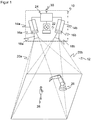
- Figure 1 shows in a schematic three-dimensional representation the general structure of a stereo camera 10 for recording a depth map.
- the stereo camera 10 is only one example of a 3D sensor according to the invention, on which the acquisition of 3D image data is explained.
- Other 3D cameras with acquisition principles such as correlation of image and projected lighting patterns or determination of the time of flight as well as laser scanners would also be conceivable.
- two camera modules 14a, 14b are mounted at a known fixed distance from one another and each record images of the spatial area 12.
- An image sensor 16a, 16b is provided in each camera, usually a matrix-shaped recording chip which records a rectangular pixel image, for example a CCD or a CMOS sensor.
- the two image sensors 16a, 16b together form a 3D image sensor for capturing a depth map.
- the image sensors 16a, 16b are each assigned an objective 18a, 18b with imaging optics, which in practice can be implemented as any known imaging objective.
- the maximum viewing angle of these optics is in Figure 1 represented by dashed lines, each forming a viewing pyramid 20a, 20b.
- An illumination unit 22 is provided between the two image sensors 16a, 16b in order to illuminate the spatial area 12 with a structured pattern.
- the stereo camera shown is accordingly designed for active stereoscopy, in which the pattern also impresses contrasts that can be evaluated everywhere on an inherently structureless scene.
- no or homogeneous lighting is provided in order to evaluate the natural object structures in the spatial region 12, which, however, regularly leads to additional image errors.
- a control and evaluation unit 24 is connected to the two image sensors 16a, 16b and the lighting unit 22.
- the control and evaluation unit 24 can be implemented in a wide variety of hardware, for example digital modules such as Microprocessors, ASICs (Application Specific Integrated Circuit), FPGAs (Field Programmable Gate Array), GPUs (Graphics Processing Unit) or mixed forms of these, which can be freely distributed to internal and external components, whereby external components can also be integrated via a network or a cloud as long as latencies can be controlled or tolerated. Since the generation of the depth map and its evaluation are very computationally intensive, an at least partially parallel architecture is preferably formed.
- the control and evaluation unit 24 generates the structured lighting pattern with the aid of the lighting unit 22 and receives image data from the image sensors 16a, 16b. From this image data, it calculates the 3D image data or the depth map of the spatial area 12 with the help of a stereoscopic disparity estimate.
- the stereo camera 10 is designed for the safe detection of an object in personal protection, preferably fail-safe in the sense of safety standards such as those mentioned in the introduction, in particular according to IEC 61496-4-3.
- the depth map in the control and evaluation unit 24 is preferably first subjected to some preprocessing steps, for example a masking out of the known background.
- the objects 28 in the spatial area 12 are then recognized, it being possible for requirements to be placed on relevant objects 28, for example a minimum size corresponding to a required detection capability. Filters based on a body model for more robustness are also conceivable, for example in the form that as in EP 3 200 122 A1 finely captured objects are only relevant if they are in the vicinity of a coarsely captured object.
- the shortest distance from the machine 26 to the next object is then calculated among the remaining objects 28.
- the projective shadow of the object 28 is taken into account, for example by assuming the shadowed area as a precaution as occupied by an object. This prevents a security-relevant object 28 from being overlooked in a shading area that is not visible from the central perspective of the stereo camera 10.
- the respective current shortest distance is provided cyclically or acyclically at a safe interface 30. Typical output rates are several times per second, but less frequent updating is also conceivable, depending on the required and possible response time of the stereo camera 10.
- a higher-level controller connected to the safe interface 30, in particular that of the machine 26, evaluates the shortest distance to fulfill a safety function, for example speed-and-separation monitoring according to ISO / TS 15066, and compares the shortest distance with a required safety distance according to ISO 13855, for example.
- a safety-related reaction is initiated, for example to stop the machine 26, to slow it down or to allow it to evade so that continuously the required safety distance between man and machine is maintained or the machine is put into a safe state.
- the reaction can depend on other conditions such as the speeds or the nature of object 28 and machine area 26 of the impending collision.
- the machine 26 itself is observed and the shortest distance to it is determined. In practice, however, this does not happen due to the very complex shape and dynamics. Instead, the machine 26 is modeled according to the invention as what are known as danger spots.
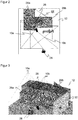
- the Figures 2 and 3 show an exemplary scenery in a plan view or three-dimensional representation.
- the monitoring is carried out here, for example, by means of a sensor network made up of two 3D sensors 10a-b, for example stereo cameras such as to Figure 1 explained, which are only represented by their respective field of view pyramids.
- the use of two 3-D sensors 10a-b is an example; instead, a single sensor or a larger 3-D sensor network can be used in order to expand the field of view or to gain additional perspectives.
- the 3D sensors 10a-b only secure towards the front, a physical barrier 32 prevents access from to the right. At the back and left, walls, other physical barriers, 3D sensors or, for example, light grids can complete the protection.
- Two danger spots 26a-b are configured around the machine 26 by way of example.
- the danger points 26a-b are spatial areas in which the machine 26 performs work movements in a respective time segment.
- the danger points 26a-b can surround the machine 26 with some distance in order to allow sufficient play for the working movements.
- several danger spots 26a-b surround several machines 26 and / or several movable subsections of a machine 26.
- Danger spots 26a-b can be rigid and include all conceivable work movements.
- danger points 26a-b are defined for partial sections of the work movement, which are used in a sequence corresponding to the process and which are smaller and better adapted.
- a danger point 26a-b itself is preferably viewed as being free of objects 28 to be detected, or rather as being blocked by the machine 26.
- the machine 26 itself naturally also forms an object 28, which is initially detected by the 3D sensors 10a-b.
- the differentiation between machine 26 and object 28 within danger point 26a-b would, however, be extremely difficult and prone to errors, with the result that the distance between machine 26 and itself is calculated and an unnecessary safety reaction then takes place. Since the danger point 26a-b together with the projective covering and shading areas are masked out for object recognition, the dynamics of the machine 26 within the danger point 26a are irrelevant. In terms of safety, this is not a problem, because each object 28 is recognized in good time when it approaches a danger point 26a-b.
- a hazard point 26a-b For efficient and safe monitoring, however, there are now some requirements for the configuration of a hazard point 26a-b.
- a hazard point 26a-b For example, for the left 3D sensor 10a on the right-hand side of the danger point 26a, denoted by an arrow, a non-visible area is created which is shaded by the danger point 26a.
- the configuration of the danger points 26a-b and the sensor network of the 3D sensors 10a-b must ensure that no object 28 goes undetected without timely safe reaction, got into a danger spot 26a-b. In the case of the critical point indicated by arrows, this is solved by the right 3D sensor 10b taking over the monitoring with a perspective that is more favorable for this.
- the 3D sensors 10a-b can work in their own coordinate system during operation, the configured danger spots 26a-b being converted using the transformations obtained during the registration.
- the 3D sensors 10a-b observe the scene from above, for example by mounting it on the ceiling. This is particularly advantageous, but not absolutely necessary. Different perspectives can also be used in the sensor network in order to effectively reduce shading areas.
- Figure 4 shows a schematic side view of the spatial area 12 detected by a 3D sensor 10 with two exemplary danger spots 26a-b.
- Different possible shortest distances from the danger points 26a-b and their projective covering and shading areas 34a-b resulting from masking out the danger points 26a-b are drawn in with dashed lines. If the projective shading area 34a-b is taken into account when calculating the distance, the distance is underestimated, which possibly leads to unnecessary safety reactions and thus an impairment of availability. For this reason, distances should preferably always be calculated directly from the danger point 26a-b itself. So that no security problem arises from this, it must then be ensured that an object 28 cannot disappear into the projective shading area 34a-b without approaching a minimum distance beforehand, noticed by the 3D sensor 10.
- danger points 26a-b may only be configured according to the invention in such a way that the outer surfaces of the danger point 26a-b are aligned with at least one 3D sensor 10 of the monitoring sensor network.
- this 3D sensor 10 it should be possible to see the entire outer surface directly, in particular without a line of sight through a danger point 26a-b. There is then no obscuration by the danger point 26a-b, and the 3D sensor 10 can use the shortest distance from the configured danger point 26a-b without a projective shadowing area 34a-b.
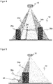
- Figure 6 shows a three-dimensional view of an example of a danger point 26a configured permissibly in this sense.
- the outer surfaces 36 of the danger point 26a are oriented towards at least one of the 3D sensors 10a-b or their respective optical center.
- the configuration according to the invention enforces such outer surfaces 36 or at least indicates which outer surfaces 36 are permissible, for example through coloring.
- Further outer surfaces 38 are marked as invalid, for example shown in red or gray. They cannot be safely monitored by the 3-D sensors 10a-b because they could create security-critical coverings or shadows.
- the setter can change the configuration so that the outer surfaces 38 can be seen, be it by adapting the outer surfaces 38, the position and / or perspective of one of the 3D sensors 10a-b or adding a further 3D sensor. Otherwise, the non-visible outer surfaces 38 are excluded from the monitoring and must be secured in some other way, for example with a fence or a light grille.
- Figure 7 illustrated in a similar view Figure 6 an exemplary correction step of a non-visible outer surface 38.
- a part 36a of the outer surface 38 is reoriented towards the front, making it visible to the 3D sensor 10a and thus permissible for monitoring.
- Figure 8 illustrated in a top view of the situation of the Figure 7 an embodiment of the configuration according to the invention.
- danger points 26a are configured as a polygon in the ground plane and provided with a height. This results in a prism with vertical side surfaces as outer surfaces.
- the polygon is initially not restricted, but should preferably not be self-intersecting and can include any number of support points, so that complex shapes are also possible. This means that there are more configuration options than with conceivable geometric primitives such as cuboids, cylinders or spheres. On the other hand, any meshes would be even more flexible, but difficult to handle both for their definition and for checking and tracing the admissibility in the sense of the mentioned visibility criterion. In general, i.e.
- an outer surface of the danger point 26a-b can be seen if the connecting line from the 3D sensor 10a-b to any point on the outer surface does not have a point of a danger point 26a -b cuts.
- the orientation of a flat outer surface towards the 3D sensor 10ab can be checked with a normal vector n of the outer surface.
- the normal vector n always points outwards from the danger point 26a-b.
- n ⁇ r 0 must apply to the scalar product.
- the connection vector r from the 3D sensor 10 to the surface therefore always points in the opposite direction to the normal vector n.
- danger spots 26a-b which are configured as a prism with vertical side surfaces from a polygon
- this check can be significantly simplified.
- n is perpendicular to the polygon segment under consideration
- r connects the projection of the optical center of the 3D sensor 10 to any point of the polygon segment, for example its start, end or center point.
- the condition for the scalar product remains n ⁇ r ⁇ 0, only that it is now a two-dimensional scalar product of the vectors projected onto the base area.
- the condition clearly means that the 3D sensor 10 with respect to a half-plane 40, which in FIG Figure 9 for example that of the outer surface 36a lies beyond the danger point 26a. This condition must be checked for each segment of the traverse using the corresponding half-planes 40.
- the check preferably takes place during the configuration or only valid polygons can be set up. This means that it is not possible to cover up behind danger spots 26a-b.
- This automatic control procedure has the advantage that only valid configurations can be created and released, at least with regard to the visibility of the side surfaces. The automatic check thus excludes these configuration errors.
- Figure 10 shows again an exemplary schematic side view of the field of view of a 3D sensor 10.
- a conceivable condition at danger spots 26a-b is that they may have any height, but always have to start on the base, which is preferably meant in a broader sense and allows a safe distance of, for example, 300 mm to the floor. This means that no relevant object 28 can disappear under a hazard point 26a-b.
- Floating danger spots 26a are therefore often not advantageous. In the situation of the Figure 10 For most applications, it would probably be better to pull the danger point 26a vertically downwards to the ground within the scope of the configuration than to actually project it obliquely over the shading area 34a.
- the shading areas 34a have mainly been viewed from the point of view of the 3D sensor 10 behind a danger point 26a. Due to the requirement of object-free danger points 26a and their masking out during the object detection, however, a concealment also arises between the danger point 26a and the 3D sensor 10 as part of the respective concealment and shadowing area 34a.
- Figure 12 again illustrates the advantage of the configuration according to the invention. Instead of paying attention to the visibility of the outer surfaces of a danger point 26a-b, it would always be possible to simply add projectively to the danger points 26a-b, that is to add the entire shading areas 34a-b to them.
- a comparison of Figure 6 and 12th shows impressively how much larger the volume occupied by danger spots 26a-b becomes. This also means that the shortest distances to objects 28 are systematically underestimated and thus availability is reduced.
- a hazard point 26a-b is difficult to understand for the fitter, and complex geometries result in the room during the subsequent calculation. Similar problems arise when hazard locations 26a-b are extracted directly from depth maps.
- danger points 26a-b using the work processes of the machine 26 or at least to support the setter in the configuration using the work processes.
- the machine 26 is monitored by one of the 3D sensors via one or more work steps. Monitoring by another 3D sensor that sees the machine 26 from a better or more complete perspective is also conceivable, or with completely different sensors, such as a robot's own sensor system as the machine 26 Machine 26 are at least temporarily occupied, and this information is used to automatically define hazard areas 26a-b, or the information is displayed to illustrate the approximately required hazard area 26a-b to the fitter. It is also conceivable to automatically predefine danger points 26a-b and then to rework them manually.
- the sequence could initially provide for the recording of 3D point clouds of the static scene as a reference and then during the work steps of the machine 26 to be monitored, possibly also several times. A kind of union is formed from this, and 3D points of the reference that are static and not part of a hazard may be ignored.
- a 3D model is created, in particular a convex envelope including projective obscuration from the sensor perspective.
- a 3D model is created for the work steps and the reference, and the 3D model is adjusted in this way.
- the resulting 3D model designates a spatial volume of all points occupied by moving parts of the machine 26. It is then automatically and / or manually reworked to form a permissible hazard point 26a-b, in which all outer surfaces can be viewed by at least one 3D sensor 10a-b.
- a permissible hazard point 26a-b in which all outer surfaces can be viewed by at least one 3D sensor 10a-b.
Landscapes
- Engineering & Computer Science (AREA)
- Physics & Mathematics (AREA)
- General Physics & Mathematics (AREA)
- Computer Vision & Pattern Recognition (AREA)
- Theoretical Computer Science (AREA)
- Multimedia (AREA)
- Signal Processing (AREA)
- Manufacturing & Machinery (AREA)
- Automation & Control Theory (AREA)
- Human Computer Interaction (AREA)
- Optics & Photonics (AREA)
- Robotics (AREA)
- Mechanical Engineering (AREA)
- Length Measuring Devices By Optical Means (AREA)
Description
Die Erfindung betrifft ein Verfahren und eine Vorrichtung zum Konfigurieren einer von einem 3D-Sensor zu überwachenden Gefahrenstelle nach dem Oberbegriff von Anspruch 1 beziehungsweise 14.The invention relates to a method and a device for configuring a hazard point to be monitored by a 3D sensor according to the preamble of claims 1 and 14, respectively.
Das primäre Ziel der Sicherheitstechnik ist, Personen vor Gefahrenquellen zu schützen, wie sie beispielsweise Maschinen im industriellen Umfeld darstellen. Die Maschine wird mit Hilfe von Sensoren überwacht, und wenn demnach eine Situation vorliegt, in der eine Person gefährlich nahe an die Maschine zu gelangen droht, wird eine geeignete Absicherungsmaßnahme ergriffen.The primary goal of safety technology is to protect people from sources of danger, such as those presented by machines in an industrial environment. The machine is monitored with the aid of sensors, and if there is a situation in which a person threatens to get dangerously close to the machine, a suitable safety measure is taken.
Für die Überwachung werden unter anderem 3D-Sensoren eingesetzt. Dazu zählen zunächst 3D-Kameras in unterschiedlichen Technologien, beispielsweise Stereoskopie, Triangulation, Lichtlaufzeit oder Auswertung der Störung passiver zweidimensionaler Muster oder von projizierten Beleuchtungsmustern. Solche 3D-Sensoren nehmen im Gegensatz zu einer üblichen zweidimensionalen Kamera Bilder auf, die in ihren Pixeln einen Abstandswert enthalten. Diese tiefenaufgelösten oder dreidimensionalen Bilddaten werden auch als Tiefenkarte bezeichnet. Weiterhin bekannt sind in zwei oder allen drei Richtungen abtastende Laserscanner, die über die jeweiligen Abtastwinkel und die gemessene Entfernung ebenfalls dreidimensionale Bilddaten erfassen. Der im Vergleich zu einer zweidimensionalen Bilderfassung höhere Geräte- und Auswertungsaufwand zur Erzeugung von dreidimensionalen Bilddaten wird in vielen Anwendungen durch die Zusatzinformationen gerechtfertigt.Among other things, 3D sensors are used for monitoring. This initially includes 3D cameras in different technologies, for example stereoscopy, triangulation, time of flight or evaluation of the disturbance of passive two-dimensional patterns or of projected lighting patterns. In contrast to a conventional two-dimensional camera, such 3D sensors record images that contain a distance value in their pixels. This depth-resolved or three-dimensional image data is also referred to as a depth map. Also known are laser scanners which scan in two or all three directions and which likewise acquire three-dimensional image data via the respective scanning angle and the measured distance. The higher equipment and evaluation effort for generating three-dimensional image data compared to two-dimensional image acquisition is justified in many applications by the additional information.
In der Sicherheitstechnik beziehungsweise für den Personenschutz eingesetzte Sensoren müssen besonders zuverlässig arbeiten und deshalb hohe Sicherheitsanforderungen erfüllen, beispielsweise die Norm EN13849 für Maschinensicherheit und die Gerätenorm IEC61496 oder EN61496 für berührungslos wirkende Schutzeinrichtungen (BWS). Zur Erfüllung dieser Sicherheitsnormen sind eine Reihe von Maßnahmen zu treffen, wie sichere elektronische Auswertung durch redundante, diversitäre Elektronik, Funktionsüberwachung oder speziell Überwachung der Verschmutzung optischer Bauteile. In sicherheitstechnischen Anwendungen wird typischerweise gefordert, dass ein Objekt mit bestimmter Mindestgröße beziehungsweise bestimmten Mindestabmessungen sicher erkannt wird. Diese Eigenschaft wird als Detektionsvermögen bezeichnet.Sensors used in safety technology or for personal protection must work particularly reliably and therefore meet high safety requirements, for example the EN13849 standard for machine safety and the Device standard IEC61496 or EN61496 for electro-sensitive protective equipment (ESPE). A number of measures must be taken to meet these safety standards, such as safe electronic evaluation through redundant, diverse electronics, function monitoring or, in particular, monitoring of the contamination of optical components. In safety-related applications, it is typically required that an object with a certain minimum size or certain minimum dimensions is reliably detected. This property is called detection capability.
Das gängige Absicherungskonzept sieht vor, dass Schutzfelder konfiguriert werden, die während des Betriebs der Maschine vom Bedienpersonal nicht betreten werden dürfen. Erkennt der Sensor einen unzulässigen Schutzfeldeingriff, etwa ein Bein einer Bedienperson, so löst er einen sicherheitsgerichteten Halt der Maschine aus.The current protection concept provides that protective fields are configured that are not allowed to be entered by the operating personnel while the machine is in operation. If the sensor detects an impermissible protective field interference, for example an operator's leg, it triggers a safety-related stop of the machine.
In der sicherheitstechnischen Überwachung von Robotern besteht ein zunehmender Wunsch nach engerer Zusammenarbeit mit Personen (MRK, Mensch-Roboter-Kollaboration). Relevante Normen in diesem Zusammenhang sind beispielsweise die ISO 10218 für Industrieroboter oder die ISO 15066 für kollaborierende Roboter. In der MRK sollten Schutzfelder und Sicherheitsabstände möglichst klein und eventuell sogar situationsangepasst konfiguriert werden, natürlich unter der Vorgabe, dass die Sicherheit gewährleistet bleibt. Die Normen ISO13854, ISO 13855, ISO 13857 befassen sich mit der Festlegung von Sicherheitsabständen.In the safety-related monitoring of robots, there is an increasing desire for closer cooperation with people (HRC, human-robot collaboration). Relevant standards in this context are, for example, ISO 10218 for industrial robots or ISO 15066 for collaborative robots. In the HRC, protective fields and safety distances should be configured as small as possible and possibly even adapted to the situation, of course with the stipulation that safety remains guaranteed. The standards ISO13854, ISO 13855, ISO 13857 deal with the definition of safety distances.
Eine Bewertung von Objekten und Maschinen bezüglich Geschwindigkeit und gegenseitiger Entfernung wird in den genannten Roboternormen als "Speed and Separation Monitoring" bezeichnet. Dabei wird zweckmäßigerweise nicht der Abstand zu der Maschine selbst berechnet. Das wäre zu komplex und dynamisch, und es soll auch ein ausreichender Sicherheitsabstand zu künftigen Maschinenpositionen eingehalten werden. Deshalb ist es sinnvoll, eine Gefahrenstelle zu konfigurieren, welche die Maschine umgibt.An evaluation of objects and machines with regard to speed and mutual distance is referred to as "speed and separation monitoring" in the robot standards mentioned. The distance to the machine itself is expediently not calculated. That would be too complex and dynamic, and there should also be a sufficient safety distance to future machine positions. It therefore makes sense to configure a hazard area that surrounds the machine.
Nach den dafür bekannten Verfahren wird aber der Einrichter nicht dahingehend unterstützt, ob die Konfiguration sicher ist. Werden jedoch Verdeckungen und Abschattungen ignoriert, die eine konfigurierte Gefahrenstelle verursacht, so kann darunter die Sicherheitsfunktion leiden, weil Objekte aus der Perspektive des überwachenden Sensors nicht zu sehen sind oder plötzlich in der Gefahrenstelle verschwinden. Der Einrichter wird mit der Verantwortung allein gelassen, dass eine Konfiguration die gewünschte Sicherheit bietet.According to the methods known for this, however, the setter is not supported in determining whether the configuration is safe. However, if coverings and shadows caused by a configured danger zone are ignored, the safety function can suffer because objects cannot be seen from the perspective of the monitoring sensor or suddenly disappear in the danger zone. The setter is left with the responsibility to ensure that a configuration offers the desired level of security.
Die
In der
Die
Bei einer Konfiguration eines optoelektronischen Sensors nach
Die
Nach der
Die
Die
In der
Die
Die
Die
Die
Aus der
Es ist daher Aufgabe der Erfindung, das Konfigurieren von Gefahrenstellen für deren 3D-Überwachung zu verbessern.It is therefore the object of the invention to improve the configuration of danger spots for their 3D monitoring.
Diese Aufgabe wird durch ein Verfahren und eine Vorrichtung zum Konfigurieren mindestens einer von mindestens einem 3D-Sensor zu überwachenden Gefahrenstelle nach Anspruch 1 beziehungsweise 14 gelöst. Die Gefahrenstelle sichert mindestens eine Maschine ab und wird von dem 3D-Sensor überwacht, damit niemand von der Maschine verletzt wird. Dazu liegt bevorzugt die Maschine zumindest teilweise in der Gefahrenstelle. Eine Gefahrenstelle ist ein durch seine Außenflächen bestimmtes Volumen, also ein 3D-Raumbereich. Gefahrenstellen können auch aus mehreren überlappenden oder disjunkten Volumina zusammengesetzt sein. Durch das erfindungsgemäße Konfigurieren werden die Außenflächen festgelegt, bevorzugt durch Erstellen eines Datensatzes, welcher die konfigurierte Gefahrenstelle beschreibt und welchen der 3D-Sensor oder ein übergeordnetes System für die Überwachung verwendet.This object is achieved by a method and a device for configuring at least one hazard point to be monitored by at least one 3D sensor according to claims 1 and 14, respectively. The danger point protects at least one machine and is monitored by the 3D sensor so that nobody is injured by the machine. For this purpose, the machine is preferably at least partially in the danger zone. A danger point is a volume determined by its outer surfaces, i.e. a 3D spatial area. Hazardous locations can also be composed of several overlapping or disjoint volumes. The configuration according to the invention defines the outer surfaces, preferably by creating a data record which describes the configured hazard point and which the 3D sensor or a higher-level system uses for monitoring.
Die Außenflächen sind deshalb entscheidend, weil im Betrieb überwacht wird, ob sich eine Person der Maschine gefährlich annähert, und dafür kommt es auf den Grenzbereich an. Selbstverständlich kann dennoch direkt ein 3D-Körper konfiguriert werden, der das Festlegen seiner Außenflächen impliziert. Insbesondere geht es um die lateralen Seitenflächen, die durch ausreichende Dimensionierung ein Unterkriechen und Übergreifen verhindern. Dabei wird sprachlich von einer bevorzugten Montage des 3D-Sensors in Vogelperspektive ausgegangen, ohne die Erfindung tatsächlich darauf zu beschränken.The outer surfaces are crucial because it is monitored during operation whether a person is approaching the machine dangerously, and this depends on the limit area. Of course, a 3D body can still be configured directly, which implies the definition of its outer surfaces. In particular, it is about the lateral side surfaces, which prevent crawling under and reaching over through adequate dimensioning. In terms of language, it is assumed that the 3D sensor is preferably mounted in a bird's eye view, without actually restricting the invention to this.
Die Erfindung geht von dem Grundgedanken aus, dass mit dem Konfigurieren sichergestellt wird, dass die Gefahrenstelle für eine sichere Überwachung geeignet ist. Dazu wird überprüft, ob Außenflächen von mindestens einem 3D-Sensor einsehbar sind. Es können alle Außenflächen geprüft werden, bevorzugt aber nur eine Teilmenge davon, beispielsweise die lateralen Seitenflächen. Allgemein können überwachte Außenflächen als Teilmenge der Außenflächen festgelegt werden, sei es durch Automatismus oder Benutzereingabe, und die überwachten Außenflächen sind diejenigen, die auf Einsehbarkeit geprüft werden. Andere Außenflächen werden beispielsweise mechanisch abgesichert und sind deshalb keine überwachten Außenflächen.The invention is based on the basic idea that the configuration ensures that the hazard point is suitable for safe monitoring. For this purpose, it is checked whether the outer surfaces can be seen by at least one 3D sensor. All outer surfaces can be checked, but preferably only a subset of them, for example the lateral side surfaces. In general, monitored exterior areas can be defined as a subset of the exterior areas, be it by automation or user input, and the monitored exterior areas are those that are checked for visibility. Other external areas are, for example, mechanically secured and are therefore not monitored external areas.
Dabei bedeutet einsehbar eine freie Sicht im Sinne einer vollflächigen, direkten Überwachungsmöglichkeit. Eine aus Perspektive des 3D-Sensors rückwärtige Außenfläche dagegen kann in gewissem Sinne durch die Gefahrenstelle hindurch auch beobachtet werden, aber das ist gerade nicht einsehbar im erfindungsgemäßen Sinne, weil die Maschine die Sicht in recht unvorhersehbarer Weise behindert. Es reicht folglich keineswegs aus, wenn sich eine Außenfläche irgendwie im Sichtfeld befindet. Der 3D-Sensor beziehungsweise ein Verbund aus mehreren 3D-Sensoren, die einander in Sichtbereich und/oder Perspektive ergänzen, kann also mit erfindungsgemäß konfigurierten Gefahrenstellen seine Aufgabe verlässlich wahrnehmen.Visible means an unobstructed view in the sense of a full-area, direct monitoring option. On the other hand, an outer surface that is rearward from the perspective of the 3D sensor can in a certain sense also be observed through the danger point, but that is precisely not visible in the sense of the invention because the machine obstructs the view in a very unpredictable manner. It is therefore by no means sufficient if an external surface is somehow in the field of vision. The 3-D sensor or a combination of several 3-D sensors, which complement each other in the field of vision and / or perspective, can therefore reliably perform its task with hazard areas configured according to the invention.
Die Erfindung hat den Vorteil, dass mit den so konfigurierten Gefahrenstellen Sicherheitsprobleme durch Verdeckung beziehungsweise Abschattung von vorneherein vermieden werden. Der Einrichter wird automatisch unterstützt und kann keine in diesem Sinne unzulässigen Gefahrenstellen konfigurieren oder erhält zumindest einen deutlichen Hinweis auf mögliche Sicherheitsprobleme. In diesem Rahmen bleibt eine große Flexibilität der konfigurierbaren Gefahrenstellen gewahrt. Dadurch sind eng an die eigentliche Gefahr anliegende Gefahrenstellen möglich, bei denen die Verfügbarkeit des Systems hoch bleibt und Abstände von Objekten nicht zu stark unterschätzt werden. Das Verfahren ist auch für mehrere Gefahrenstellen zur Absicherung komplexer Maschinen und Anlagen und/oder mehrere 3D-Sensoren geeignet, die einander im Verbund ergänzenThe invention has the advantage that with the danger spots configured in this way, security problems due to covering or shading are avoided from the outset. The setter is automatically supported and cannot configure any dangerous areas that are not permitted in this sense or at least receives a clear indication of possible safety problems. In this context, there remains a big one Flexibility of the configurable danger zones is guaranteed. This enables danger spots that are close to the actual danger, in which the availability of the system remains high and distances from objects are not too greatly underestimated. The method is also suitable for several danger points to protect complex machines and systems and / or several 3D sensors that complement each other
Der 3D-Sensor ist vorzugsweise eine 3D-Kamera, die zunächst jede bekannte Technik verwenden kann, wie ein Lichtlaufzeitprinzip mit direkter Laufzeitmessung von Lichtsignalen oder Phasenmessung oder eine Entfernungsschätzung aus Helligkeiten oder Fokuslagen (DFF, Depth from Focus, DFD, Depth from Defocus). Besonders bevorzugt nutzt die 3D-Kamera aber ein Triangulationsprinzip, bei dem zwei Kamerabilder einer bewegten Kamera oder einer Stereokamera untereinander korreliert werden, oder alternativ ein Beleuchtungsmuster mit einem Kamerabild korreliert wird, um so Disparitäten zu schätzen und daraus Abstände zu bestimmen. Auch ein Laserscanner ist ein 3D-Sensor, denn er erzeugt 3D-Punktwolken, die bei einem klassischen Laserscanner auf eine Abtastebene beschränkt sind. Durch in Elevation bewegte Abtastung oder mehrere in Elevation versetzte Abtaststrahlen entfällt diese Beschränkung bei einem Laserscanner. Hybridanordnungen mit unterschiedlichen 3D-Sensoren oder sonstigen Sensoren, wie einem Lichtgitter, sind ebenfalls denkbar.The 3D sensor is preferably a 3D camera that can initially use any known technology, such as a light transit time principle with direct transit time measurement of light signals or phase measurement or a distance estimate from brightness or focus positions (DFF, Depth from Focus, DFD, Depth from Defocus). However, the 3D camera particularly preferably uses a triangulation principle in which two camera images from a moving camera or a stereo camera are correlated with one another, or alternatively an illumination pattern is correlated with a camera image in order to estimate disparities and determine distances from them. A laser scanner is also a 3D sensor because it generates 3D point clouds that are limited to one scanning plane in a classic laser scanner. By scanning moved in elevation or by several scanning beams offset in elevation, this restriction does not apply to a laser scanner. Hybrid arrangements with different 3D sensors or other sensors, such as a light grid, are also conceivable.
Vorzugsweise wird zum Konfigurieren von Außenflächen mindestens ein Polygonzug auf einer Grundfläche vorgegeben, insbesondere ein geschlossener Polygonzug, und daraus ein Prisma mit senkrechten Außenflächen erzeugt. Die Vorgabe des Polygonzuges auf der Grundfläche ist nur eine sprachliche Vereinfachung, da der Polygonzug bei einem Prisma mit senkrechten Seitenflächen in jeder Höhe derselbe ist. Über einen Polygonzug beziehungsweise ein daraus automatisch erzeugbares Prisma wird ein guter Kompromiss gefunden, der zugleich flexible, ausreichend komplexen Konfigurationsmöglichkeiten für Gefahrenstellen erlaubt und dabei sicherheitstechnisch wesentlich besser beherrschbar ist als ein beliebiges 3D-Volumen. Auch für den Einrichter sind solche durch Prismen mit senkrechten Seitenflächen beschriebene Gefahrenstellen leichter nachvollziehbar und testbar. Das Prisma ist vorzugsweise kein Quader und/oder keine Dreieckssäule. Zwar sollen solche einfachen Gefahrenstellen ausdrücklich konfigurierbar und keineswegs verboten sein. Es geht nur um ein optionales eingeschränktes Begriffsverständnis eines Polygonzugs und des dadurch festgelegten Prismas, das tatsächlich von den flexibleren und komplexeren Gestaltungsmöglichkeiten Gebrauch macht. Gefahrenstellen können aus mehreren Prismen zusammengesetzt sein, die über mehrere Polygonzüge vorgegeben werden.In order to configure outer surfaces, at least one polygon course is preferably specified on a base area, in particular a closed polygon course, and a prism with perpendicular outer surfaces is generated therefrom. The specification of the polygon on the base is only a linguistic simplification, since the polygon is the same for a prism with vertical side surfaces at every height. A good compromise is found using a polygon or a prism that can be automatically generated from it, which at the same time allows flexible, sufficiently complex configuration options for danger spots and is much more controllable in terms of safety than any 3D volume. For the fitter, too, such danger spots described by prisms with vertical side surfaces are easier to understand and test. The prism is preferably not a cuboid and / or not a triangular column. It is true that such simple danger spots should be expressly configurable and by no means prohibited. It is only about an optional restricted understanding of the concept of a polygon and the prism defined by it, which actually makes use of the more flexible and complex design options power. Hazardous areas can be composed of several prisms, which are specified via several polygonal lines.
Eine Außenfläche kann von einem 3D-Sensor eingesehen werden, wenn der 3D-Sensor bezüglich der Ebene, in der die Außenfläche liegt, jenseits der Gefahrenstelle angeordnet ist. Dies ist eine vorteilhafte und einfach überprüfbare Bedingung, wann eine Außenfläche einsehbar ist. Es genügt, wenn ein 3D-Sensor in einem Verbund mehrerer 3D-Sensoren diese Bedingung erfüllt. Die Außenfläche wird in alle Richtungen ausgedehnt, um eine Ebene zu bilden. Auf der einen Seite dieser Ebene liegt die Gefahrenstelle selbst, das ist gleichsam innen. Befindet sich der 3D-Sensor auf der anderen Seite, also außen, so kann davon die gesamte Außenfläche frei eingesehen werden. Formal kann der Normalenvektor zu der Außenfläche bestimmt und mit einem Vektor von der Position des 3D-Sensors zu der Außenfläche verglichen werden. Sie sollten einander entgegengesetzt orientiert, also beispielsweise das Vorzeichen ihres Skalarprodukts negativ sein. Diese Betrachtung kann auch in nur zwei Dimensionen in einer senkrechten Projektion auf eine Ebene parallel zu der Grundfläche erfolgen.An outer surface can be viewed by a 3D sensor if the 3D sensor is arranged on the other side of the danger point with respect to the plane in which the outer surface lies. This is an advantageous and easily verifiable condition for when an outer surface can be viewed. It is sufficient if a 3D sensor in a network of several 3D sensors fulfills this condition. The outer surface is expanded in all directions to form a plane. On one side of this level lies the danger point itself, which is, as it were, inside. If the 3D sensor is on the other side, i.e. outside, the entire outer surface can be viewed freely. Formally, the normal vector to the outer surface can be determined and compared with a vector from the position of the 3D sensor to the outer surface. They should be oriented opposite to one another, so for example the sign of their scalar product should be negative. This observation can also take place in only two dimensions in a perpendicular projection onto a plane parallel to the base area.
Gefahrenstellen dürfen vorzugsweise nur mit Kontakt zum Boden konfiguriert werden. Kontakt zum Boden ist hier vorzugsweise im Sinne der Normen zu verstehen, so dass ein Unterkriechen und ein Zugang vom Boden her unmöglich sind. Ein kleiner Abstand zum Boden insbesondere entsprechend dem Detektionsvermögen des 3D-Sensors kann verbleiben, da dies sicherheitstechnisch nicht relevant ist. Eine konkrete Größe für einen derartigen normgerechten, unbedenklichen Abstand zum Boden ist 300 mm. Bei Gefahrenstellen mit Kontakt zum Boden, auch in dem genannten erweiterten Sinne, muss keine Abschattung nach unten berücksichtigt werden. Werden alternativ doch schwebende Gefahrenstellen zugelassen, so wird vorzugsweise der Gefahrenstelle deren projektiver Abschattungsbereich zugeschlagen. Der projektive Abschattungsbereich ist der Bereich, der für einen 3D-Sensor aus dessen Zentralperspektive durch die Gefahrenstelle abgeschattet ist. Wie später noch ausgeführt, ist ein großer Vorteil erfindungsgemäß konfigurierter Gefahrenstellen, dass Abstände ohne Berücksichtigung projektiver Abschattungen der Gefahrenstelle bestimmt werden können. Das geht aber nur, wenn die Gefahrenstelle mit Kontakt zum Boden konfiguriert ist, bei einer schwebenden Gefahrenstelle muss die Sicherheit durch Berücksichtigung des projektiven Schattens wiederhergestellt werden.Hazardous areas may preferably only be configured with contact with the ground. Contact with the floor is to be understood here preferably in the sense of the standards, so that crawling under and access from the floor are impossible. A small distance from the floor, in particular according to the detection capability of the 3D sensor, can remain, since this is not relevant from a safety point of view. A specific size for such a standard, harmless distance to the floor is 300 mm. In the case of danger spots with contact with the ground, even in the aforementioned extended sense, there is no need to consider shading downwards. If, as an alternative, floating hazard areas are permitted, the projective shadow area is preferably added to the hazard area. The projective shading area is the area that is shaded by the danger point for a 3D sensor from its central perspective. As will be explained later, a great advantage of danger spots configured according to the invention is that distances can be determined without taking into account projective shadowing of the danger spot. However, this is only possible if the danger point is configured with contact to the ground; in the case of a floating danger point, safety must be restored by taking into account the projective shadow.
Vorzugsweise wird eine Außenfläche, die nicht von mindestens einem 3D-Sensor eingesehen wird, während des Konfigurierens gekennzeichnet oder gar nicht zugelassen. Das erleichtert dem Einrichter seine Aufgabe erheblich, da es gar nicht erst zum Konfigurieren von ungültigen Gefahrenstellen kommt. Es kann aber die Möglichkeit nicht aktivierter Außenflächen einer Gefahrenstelle geben, d. h. von Außenflächen, für deren Absicherung ein zusätzlicher 3D-Sensor oder eine andere Maßnahme wie eine physische Absperrung oder ein Lichtgitter erforderlich ist. Solche Sicherheitsprobleme oder Lücken in der Überwachung sind für den Einrichter sofort erfassbar.An outer surface that is not viewed by at least one 3D sensor is preferably identified during configuration or not allowed at all. This makes his job considerably easier for the fitter, as there is no need to configure invalid hazard areas in the first place. However, there may be the possibility of non-activated outer surfaces of a hazard area, i.e. H. of external areas that require an additional 3D sensor or other measure such as a physical barrier or a light grille to secure them. Such security problems or gaps in monitoring can be detected immediately by the setter.
Beim Konfigurieren einer nicht von mindestens einem 3D-Sensor eingesehenen Außenfläche wird bevorzugt automatisch eine alternative Außenfläche vorgeschlagen. Das ist beispielsweise eine Außenfläche, die einsehbar ist, und minimalen Abstand zu einer unzulässigen, nicht einsehbaren Außenfläche hat, die der Einrichter vorgibt. Damit gelangt der Einrichter besonders schnell zu einer alternativen, zulässigen Konfiguration, die seinem ursprünglichen Plan nahe kommt.When configuring an outer surface that is not viewed by at least one 3D sensor, an alternative outer surface is preferably automatically proposed. This is, for example, an outer surface that can be seen and is at a minimum distance from an impermissible, non-visible outer surface specified by the fitter. This enables the setter to arrive particularly quickly at an alternative, permissible configuration that comes close to his original plan.
Beim Konfigurieren einer nicht von mindestens einem 3D-Sensor eingesehenen Außenfläche wird bevorzugt automatisch eine veränderte Perspektive eines 3D-Sensors oder eine Perspektive eines zusätzlichen 3D-Sensors vorgeschlagen, damit die Außenfläche dann eingesehen wird. In dieser Ausführungsform wird, um das Problem einer nicht einsehbaren Außenfläche zu beheben, nicht bei der Konfiguration der Gefahrenstelle angesetzt, sondern bei der 3D-Sensoranordnung. Sofern mit allen bisher konfigurierten Gefahrenstellen verträglich denkbar, wird eine neue Position und/oder Ausrichtung eines schon vorgesehenen 3D-Sensors verändert. Ansonsten wird ein zusätzlicher 3D-Sensor ergänzt, mit dessen Hilfe die Konfiguration möglich wäre. Funktionen wie der Vorschlag einer alternativen Außenfläche oder 3D-Sensor-Konfiguration werden vorzugsweise gesondert von dem Einrichter angefordert beziehungsweise sind abschaltbar, weil sie sonst vor allem zu Beginn einer Konfiguration sehr störend werden können.When configuring an outer surface that is not viewed by at least one 3D sensor, a changed perspective of a 3D sensor or a perspective of an additional 3D sensor is preferably automatically proposed so that the outer surface can then be viewed. In this embodiment, in order to remedy the problem of a non-visible outer surface, the starting point is not the configuration of the danger point, but rather the 3D sensor arrangement. If it is conceivable to be compatible with all previously configured hazard areas, a new position and / or alignment of a 3D sensor that has already been configured is changed. Otherwise, an additional 3D sensor is added, with which the configuration would be possible. Functions such as the suggestion of an alternative outer surface or 3D sensor configuration are preferably requested separately by the setter or can be switched off, because otherwise they can become very disruptive, especially at the beginning of a configuration.
Die Maschine wird vorzugsweise während ihrer Arbeitsbewegung beobachtet, um von der Gefahrenstelle zu umfassende Raumbereiche aufzufinden. Dadurch werden Ausgangsdaten bereitgestellt, die bei der Konfiguration der Gefahrenstelle unterstützen. Es ist danach bekannt, welche Raumbereiche von der Maschine mindestens zeitweise besetzt werden und welche nicht.The machine is preferably observed during its working movement in order to find spatial areas that are too extensive from the danger point. This provides output data that support the configuration of the danger zone. It is then known which areas of the room are at least temporarily occupied by the machine and which are not.
Die zu umfassenden Raumbereiche werden bevorzugt als Hilfestellung zum Konfigurieren der Gefahrenstelle dargestellt. Eine derartige Darstellung erfolgt beispielsweise durch Einblenden in einer Konfigurationssoftware oder durch Projektion in den tatsächlich überwachten Bereich. Der Einrichter kennt damit die Bereiche, die von der Maschine eingenommen werden, und kann die Gefahrenstelle daran anpassen.The spatial areas that are too extensive are preferably shown as an aid to configuring the danger zone. Such a representation takes place, for example, by fading in a configuration software or by projection into the area actually monitored. The setter knows the areas that are occupied by the machine and can adapt the danger zone accordingly.
Vorzugsweise wird anhand der zu umfassenden Raumbereiche automatisch eine Gefahrenstelle konfiguriert. Beispielsweise wird mit Hilfe des 3D-Sensors, alternativ eines anderen Sensors, eine kumulierte 3D-Punktwolke der Maschine über ihre Arbeitsbewegung erzeugt. Die 3D-Messpunkte werden auf den Boden projiziert, es wird ein umhüllender Polygonzug gebildet, und gegebenenfalls werden dessen Abschnitte noch zu einem der beobachtenden 3D-Sensoren hin gedreht, damit die entsprechende Außenfläche einsehbar wird. Je nach Position der 3D-Sensoren und Komplexität der Maschine und ihrer Arbeitsbewegung verbleiben dabei nicht einsehbare Außenflächen. Der Einrichter hat die Möglichkeit, dies in einer Nachbearbeitung durch Veränderungen der Konfiguration und/oder des 3D-Sensorverbundes weiter zu verbessern, ist sich aber jedenfalls sofort der noch bestehenden Sicherheitslücken bewusst.A hazard point is preferably configured automatically on the basis of the spatial areas that are too extensive. For example, with the help of the 3D sensor, or alternatively another sensor, a cumulative 3D point cloud of the machine is generated via its working movement. The 3D measurement points are projected onto the floor, an enveloping polygon is formed and, if necessary, its sections are rotated towards one of the observing 3D sensors so that the corresponding outer surface can be seen. Depending on the position of the 3D sensors and the complexity of the machine and its working movement, external surfaces that cannot be seen remain. The setter has the option of further improving this in post-processing by changing the configuration and / or the 3D sensor network, but is in any case immediately aware of the remaining security gaps.
Die mindestens eine konfigurierte Gefahrenstelle wird vorzugsweise von dem mindestens einen 3D-Sensor überwacht, wobei aus Messdaten des 3D-Sensors Objekte in einer Umgebung der Gefahrenstelle erfasst werden, der kürzeste Abstand zwischen Gefahrenstelle und Objekten bestimmt und mit dessen Hilfe entschieden wird, ob eine sicherheitsgerichtete Reaktion der Maschine in der Gefahrenstelle erfolgt. So wird die erfindungsgemäß konfigurierte Gefahrenstelle in einer Sicherheitsanwendung genutzt. Sind mehrere Gefahrenstellen konfiguriert, so wird vorzugsweise für jede Gefahrenstelle der kürzeste Abstand zu einem von dem 3D-Sensor erfassten Objekt bestimmt. In einem 3D-Sensor-Verbund werden Erfassungsdaten geeignet fusioniert. Das kann insbesondere erst auf der Verarbeitungsstufe kürzester Abstände geschehen, jeder 3D-Sensor arbeitet dann bis zu einem sehr späten Verarbeitungsstadium weitgehend autark. Alternativ können auch bereits die Messdaten vereinigt und gemeinsam ausgewertet werden.The at least one configured hazard point is preferably monitored by the at least one 3D sensor, objects in the vicinity of the hazard point being recorded from measurement data from the 3D sensor, the shortest distance between the hazard point and objects being determined and the decision being made as to whether a safety-related one is used Reaction of the machine in the danger zone takes place. The danger point configured according to the invention is used in a safety application. If several danger spots are configured, the shortest distance to an object detected by the 3D sensor is preferably determined for each danger spot. Acquisition data are appropriately merged in a 3D sensor network. In particular, this can only happen at the processing stage of the shortest possible intervals; each 3D sensor then works largely independently up to a very late processing stage. Alternatively, the measurement data can already be combined and jointly evaluated.
Vorzugsweise werden von dem 3D-Sensor nur die kürzesten Abstände sicherheitsgerichtet bereitgestellt, und die weitere Beurteilung erfolgt auf dieser Basis in einer angeschlossenen Steuerung. Die Steuerung ist dem 3D-Sensor und der überwachten Maschine oder den überwachten Maschinen übergeordnet, oder es handelt sich um die Steuerung der Maschine selbst. Die Steuerung wertet die von dem 3D-Sensor gelieferten Abstände aus und leitet gegebenenfalls eine sicherheitsgerichtete Reaktion ein. Beispiele für eine Absicherung sind ein Nothalt, ein Abbremsen, ein Ausweichen oder ein Verbringen in eine sichere Position. Es ist denkbar, einen festen Mindestabstand vorzugeben, der etwa unter worst-case-Annahmen an Geschwindigkeiten oder aus bekannten oder vermessenen Nachlaufwegen bestimmt ist. Es sind auch dynamische Sicherheitsabstände unter anderem in Abhängigkeit von der aktuellen Geschwindigkeit der Maschine und des Objekts denkbar. In die Sicherheitsbewertung können Daten der Steuerung der Maschine einfließen.Preferably, only the shortest distances are provided in a safety-oriented manner by the 3D sensor, and the further assessment is carried out on this basis in a connected controller. The control is superordinate to the 3D sensor and the monitored machine or machines, or it is the Control of the machine itself. The control evaluates the distances supplied by the 3D sensor and, if necessary, initiates a safety-related reaction. Examples of safeguarding are an emergency stop, braking, evasive action or moving to a safe position. It is conceivable to specify a fixed minimum distance that is determined, for example, under worst-case assumptions of speeds or from known or measured overtravel paths. Dynamic safety distances are also conceivable, depending on the current speed of the machine and the object, among other things. Data from the machine control can be included in the safety assessment.
Herkömmlich wird über eine solche Ausgabeschnittstelle nur ein binäres Signal ausgegeben, ob eine Schutzfeldverletzung vorliegt (OSSD, Output Signal Switching Device). Nach dieser bevorzugten Ausführungsform werden nicht mehr Schutzfelder überwacht und auch nicht mehr durch den Sensor selbst binäre Absicherungssignale erzeugt und ausgegeben. Stattdessen wird die dafür erforderliche Information sicher, sehr kompakt und leicht zugänglich bereitgestellt. Der jeweils aktuelle kürzeste Abstand wird anstelle des bisher üblichen binären Absicherungssignals an der folglich nicht mehr als OSSD ausgestalteten sicheren Ausgabeschnittstelle für eine angeschlossene Steuerung zur Verfügung gestellt. Diese Steuerung, etwa die übergeordnete Steuerung einer Roboterzelle oder auch die Steuerung des Roboters selbst, kann anhand des kürzesten Abstands sehr einfach feststellen, ob eine Gefahr besteht, und übernimmt die eigentliche Absicherungsfunktion selbst.Conventionally, only a binary signal is output via such an output interface as to whether a protective field has been violated (OSSD, Output Signal Switching Device). According to this preferred embodiment, protective fields are no longer monitored and binary protection signals are no longer generated and output by the sensor itself. Instead, the information required for this is provided in a secure, very compact and easily accessible manner. The respective current shortest distance is made available for a connected controller instead of the binary protection signal that was customary up to now at the safe output interface, which is consequently no longer designed as an OSSD. This control, such as the higher-level control of a robot cell or the control of the robot itself, can very easily determine whether there is a danger based on the shortest distance and takes on the actual safety function itself.
Dabei wird das Arbeiten beziehungsweise die Kooperation mit Maschinen wesentlich flexibler gestaltbar und eine rasche, individuelle Reaktion auf Menschen im Umfeld der Maschine ermöglicht. Ein Eingriff in ein Schutzfeld lässt in der Regel nur noch einen Nothalt zu, da Schutzfelder gerade so definiert sind, dass in einem solchen Fall eine aufgrund des binären Abschaltsignals nicht mehr differenzierte Unfallgefahr besteht. Durch Überwachung von kürzesten Abständen sind jedoch auch mildere Eingriffe in den Prozessablauf möglich, die einen zeitaufwändigen Nothalt samt Wiederanlauf vermeiden und den Prozessablauf nach Möglichkeit ungestört weiterlaufen lassen oder die Annährung eines Menschen in den Prozessablauf integrieren. Arbeitsschritte der Maschine können dabei rechtzeitig umgeplant werden.Work or cooperation with machines can be designed much more flexibly and a quick, individual reaction to people in the machine's environment is made possible. An intervention in a protective field usually only allows an emergency stop, since protective fields are defined in such a way that in such a case there is a risk of accident that is no longer differentiated due to the binary switch-off signal. By monitoring the shortest intervals, however, milder interventions in the process flow are also possible, which avoid a time-consuming emergency stop including restart and allow the process flow to continue undisturbed if possible or integrate the approach of a person into the process flow. Work steps of the machine can be rescheduled in good time.
Der kürzeste Abstand wird vorzugsweise zu den Außenflächen bestimmt, ohne den projektiven Abschattungsbereich der Gefahrenstelle zu berücksichtigen. Das wäre im Allgemeinen nicht sicher. Der projektive Schatten ist ja gerade definiert als der Bereich, in dem der 3D-Sensor aufgrund der Abschattung durch die Gefahrenstelle aus seiner Zentralperspektive blind ist. Somit könnte sich ein Objekt bei Eintritt in den projektiven Schatten noch weit genug von der Gefahrenstelle sein und sich dann im projektiven Schatten ungesehen auf eine kritische Entfernung nähern. Die erfindungsgemäße Konfiguration der Gefahrenstelle schließt aber aus, dass dieser sicherheitskritische Fall je auftritt. Der projektive Schatten nimmt ein erhebliches Raumvolumen ein und hätte entsprechenden Einfluss auf die Verfügbarkeit, so dass es ein großer Vorteil ist, wenn darauf bei der Überwachung keine Rücksicht genommen werden muss.The shortest distance is preferably determined to the outer surfaces without taking into account the projective shading area of the danger point. That would generally not be safe. The projective shadow is precisely defined as the area in which the 3D sensor is blind from its central perspective due to the shadowing by the danger point. Thus, when an object enters the projective shadow, it could still be far enough from the danger point and then approach a critical distance unseen in the projective shadow. The configuration of the hazard point according to the invention, however, precludes this safety-critical case from ever occurring. The projective shadow takes up a considerable amount of space and would have a corresponding influence on the availability, so that it is a great advantage if this does not have to be taken into account during monitoring.
Bei der Überwachung der Gefahrenstelle werden vorzugsweise Objekte in der Gefahrenstelle selbst ignoriert. Die Gefahrenstelle selbst wird also als frei von zu erfassenden Objekten angesehen, oder vielmehr als durch die Maschine blockiert. Tatsächlich wäre je nach Konfiguration durchaus Raum für solche Objekte. Auch bildet die Maschine natürlich selbst ein Objekt, das zunächst von dem 3D-Sensor erfasst wird. All das wird aber absichtlich ignoriert und die Gefahrenstelle als leerer, von Objekten freier Block modelliert. Das vereinfacht die Überwachung und die Bestimmung kürzester Abstände, denn die Dynamik der Maschine innerhalb der Gefahrenstelle spielt so keine Rolle. Sicherheitstechnisch ist dies auch unproblematisch, denn jedes Objekt wird rechtzeitig erkannt, wenn es sich der Gefahrenstelle nähert.When monitoring the hazard point, objects in the hazard point itself are preferably ignored. The danger point itself is therefore viewed as free of objects to be detected, or rather as blocked by the machine. In fact, depending on the configuration, there would be plenty of room for such objects. Of course, the machine itself also forms an object that is initially detected by the 3D sensor. However, all of this is deliberately ignored and the danger point is modeled as an empty block free of objects. This simplifies the monitoring and the determination of the shortest distances, because the dynamics of the machine within the danger point are irrelevant. In terms of safety, this is also unproblematic, because every object is recognized in good time when it approaches the danger zone.
Zu der Gefahrenstelle gehört nicht nur deren projektiver Schatten auf der dem 3D-Sensor abgewandten Seite, sondern auch ein Verdeckungsbereich auf der zugewandten Seite zwischen 3D-Sensor und Gefahrenstelle. Wird nämlich die Gefahrenstelle in dem Sinne rechentechnisch vorteilhaft ausmaskiert, dass Sichtstrahlen in die Gefahrenstelle insgesamt ignoriert werden, so ist der 3D-Sensor auch in dem Verdeckungsbereich blind. Überraschenderweise ist das aber bei erfindungsgemäß konfigurierten Gefahrenstellen unkritisch, der Verdeckungsbereich muss nicht gesondert behandelt werden. Objekte in dem Verdeckungsbereich können vielmehr ohne Sicherheitseinbuße ignoriert werden. Ein Objekt, das sich der Gefahrenstelle nähert, berührt nämlich, je nach Höhe, durch den eigenen projektiven Schatten unten die Gefahrenstelle genau dann, wenn es oben den Verdeckungsbereich berührt. Die gefährliche Annäherung wird also immer rechtzeitig bemerkt.The danger point not only includes its projective shadow on the side facing away from the 3D sensor, but also a concealment area on the facing side between the 3D sensor and the danger point. If the danger point is masked out in a computationally advantageous manner in the sense that lines of sight into the danger point are ignored as a whole, then the 3D sensor is also blind in the concealment area. Surprisingly, however, this is not critical in the case of danger spots configured according to the invention, and the concealment area does not have to be treated separately. Rather, objects in the concealment area can be ignored without compromising security. An object that is approaching the danger point, depending on its height, touches the danger point through its own projective shadow below exactly when it touches the concealment area above. The dangerous approach is always noticed in good time.
Die Steuer- und Auswertungseinheit ist bevorzugt dafür ausgebildet, mindestens eine Zusatzinformation an der Ausgabeschnittstelle bereitzustellen, wobei die Zusatzinformation mindestens einen weiteren kürzesten Abstand zu anderen Abschnitten des nächsten Objekts oder anderen Objekten, eine Objektposition, eine Bewegungsrichtung, eine Geschwindigkeit, eine Objekthülle oder eine Objektwolke aufweist. Damit wird einer an den 3D-Sensor angeschlossenen Steuerung eine differenzierte Auswertung ermöglicht. Es ist beispielsweise denkbar, dass nicht ein langsames nächstes Objekt, sondern ein schnelles etwas ferneres Objekt die größte Gefahr darstellt. Der mindestens eine zusätzliche kürzeste Abstand sollte ein anderes Objekt oder zumindest einen klar separierten anderen Objektbereich betreffen, wie einen anderen Arm, da sonst nur unmittelbare Nachbarpunkte zum kürzesten Abstand betrachtet würden, deren Zusatzinformation wenig Neues beiträgt. Objektpositionen sind hier vorzugsweise repräsentativ, etwa ein Objektschwerpunkt oder derjenige Objektpunkt, zu dem der kürzeste Abstand berechnet wurde. Es ist aber auch denkbar, Hüllkörper zu Objekten oder die 3D-Punktwolke des Objekts auszugeben. Bei allen diesen Zusatzinformationen handelt es sich jeweils um Zwischenergebnisse, die beim Auffinden des kürzesten Abstands ohnehin erfasst wurden, oder sehr leicht daraus ableitbare Größen, die den Aufwand nicht wesentlich erhöhen.The control and evaluation unit is preferably designed to provide at least one piece of additional information at the output interface, the additional information at least one further shortest distance to other sections of the next object or other objects, an object position, a direction of movement, a speed, an object envelope or an object cloud having. This enables a control system connected to the 3D sensor to perform a differentiated evaluation. It is conceivable, for example, that the greatest danger is not a slow next object, but a fast, somewhat distant object. The at least one additional shortest distance should relate to another object or at least a clearly separated other object area, such as another arm, since otherwise only points immediately adjacent to the shortest distance would be considered, the additional information of which does not contribute much. Object positions are preferably representative here, for example an object center of gravity or that object point to which the shortest distance was calculated. However, it is also conceivable to output enveloping bodies for objects or the 3D point cloud of the object. All of this additional information is in each case intermediate results that were recorded when the shortest distance was found, or variables that can be derived very easily and that do not significantly increase the effort.
Der 3D-Sensor ist bevorzugt für ein Detektionsvermögen ausgelegt, bei dem Objekte ab einer Mindestgröße sicher erfasst werden. Das Detektionsvermögen ist eine spezifizierte Eignung eines im Sinne der einleitenden oder vergleichbarer Normen sicheren Sensors, Objekte einer Mindestgröße im gesamten Überwachungsbereich sicher zu erfassen. Die entsprechende Auslegung des 3D-Sensors betrifft seinen Aufbau, also seine Optik, seinen Lichtempfänger und weitere mögliche, noch nicht genannte Komponenten, wie etwa eine Beleuchtung, sowie die sichere Auswertung. Das Detektionsvermögen schließt erst einmal nicht aus, dass auch kleinere Objekte erfasst werden. Für Objekte, die kleiner sind als die Mindestgröße, ist aber der Schutz nicht garantiert, beispielsweise wird ein Finger bei einem für Armschutz ausgelegten 3D-Sensor nicht sicher erfasst. Deshalb werden Objekte kleiner als die Mindestgröße möglicherweise mittels Filtern in der Auswertung ausgeschlossen. Es ist auch möglich, eine Mindestgröße oberhalb des Detektionsvermögens zu wählen, also eine an sich bereitgestellte Auflösung nicht auszunutzen. Als Zahlenbeispiele seien 14 mm für Fingerschutz oder im Bereich von 30-80 mm für den Schutz von Extremitäten genannt, insbesondere 55 mm für Oberarmschutz.The 3D sensor is preferably designed for a detection capability in which objects of a minimum size are reliably detected. The detection capability is a specified suitability of a sensor that is safe in the sense of the introductory or comparable standards to reliably detect objects of a minimum size in the entire monitoring area. The corresponding design of the 3D sensor relates to its structure, i.e. its optics, its light receiver and other possible, not yet mentioned components, such as lighting, as well as the reliable evaluation. The detection capability does not initially exclude that smaller objects are also detected. However, protection is not guaranteed for objects that are smaller than the minimum size, for example a finger is not reliably detected with a 3D sensor designed for arm protection. Therefore, objects smaller than the minimum size may be excluded from the analysis by means of filters. It is also possible to choose a minimum size above the detection capability, that is to say not to utilize a resolution that is provided per se. Numerical examples are 14 mm for finger protection or in the range of 30-80 mm for the protection of extremities, in particular 55 mm for upper arm protection.
Eine Vorrichtung zum Konfigurieren mindestens einer von mindestens einem 3D-Sensor zu überwachenden Gefahrenstelle weist eine Eingabeeinrichtung, eine Steuer- und Auswertungseinheit sowie eine Anzeige auf, wobei die Steuer- und Auswertungseinheit dafür ausgebildet ist, aufgrund von Eingaben der Eingabeeinrichtung Außenflächen der Gefahrenstelle festzulegen und auf der Anzeige darzustellen, um die Gefahrenstelle mit einem erfindungsgemäßen Verfahren zu konfigurieren. Die Konfiguration erfolgt mit Hilfe einer Software, die in einem 3D-Sensor, einem daran angeschlossenen System oder einem Konfigurationssystem dafür abläuft. Die Konfiguration kann auf einem üblichen Bildschirm, aber auch mittels virtueller Realität oder durch Überblenden von tatsächlicher und virtueller Information (augmented reality) erfolgen.A device for configuring at least one hazard point to be monitored by at least one 3D sensor has an input device, a control and evaluation unit, and a display, the control and evaluation unit being designed to define and display outer surfaces of the hazard point based on inputs from the input device the display in order to configure the danger point with a method according to the invention. The configuration is carried out with the help of software that runs in a 3D sensor, a system connected to it or a configuration system for this purpose. The configuration can take place on a conventional screen, but also by means of virtual reality or by blending actual and virtual information (augmented reality).
Die Erfindung wird nachstehend auch hinsichtlich weiterer Merkmale und Vorteile beispielhaft anhand von Ausführungsformen und unter Bezug auf die beigefügte Zeichnung näher erläutert. Die Abbildungen der Zeichnung zeigen in:
- Fig. 1
- eine schematische dreidimensionale Darstellung einer 3D-Kamera und ihres Überwachungsbereichs;
- Fig. 2
- eine beispielhafte Draufsicht auf Gefahrenstellen um abzusichernde Maschinen;
- Fig. 3
- eine dreidimensionale Ansicht für die Situation der
Figur 2 ; - Fig. 4
- eine schematische Seitenansicht des Sichtbereichs einer 3D-Kamera mit zwei beispielhaften Gefahrenstellen zur Erläuterung verschiedener Abstände zu einem Objekt;
- Fig. 5
- eine weitere schematische Seitenansicht des Sichtbereichs einer 3D-Kamera zur Erläuterung von Verdeckungen und Abschattungen;
- Fig. 6
- eine dreidimensionale Ansicht einer beispielhaften Konfiguration einer Gefahrenstelle mit den von einem 3D-Sensor einsehbaren Außenflächen;
- Fig. 7
- eine dreidimensionale Ansicht, in welcher die Konfiguration der Gefahrenstelle gemäß
Figur 6 verändert wurde, um einen zusätzlichen Teil einer Außenfläche einsehbar zu machen; - Fig. 8
- eine Draufsicht auf eine Konfiguration einer Gefahrenstelle mittels eines Polygonzugs auf einer Grundfläche;
- Fig. 9
- eine Draufsicht gemäß
Figur 8 mit einer zusätzlichen Halbebene, anhand derer die Einsehbarkeit einer Außenfläche geprüft wird; - Fig. 10
- eine weitere schematische Seitenansicht des Sichtbereichs einer 3D-Kamera zur Diskussion von schwebenden Gefahrenstellen;
- Fig. 11a-b
- schematische Seitenansichten des Sichtbereichs einer 3D-Kamera zur Diskussion eines Verdeckungsbereichs zwischen Gefahrenstelle und 3D-Kamera;
- Fig. 12
- eine dreidimensionale Ansicht auf Gefahrenstellen um abzusichernder Maschinen, die Verdeckungs- und Abschattungsbereiche einschließen.
- Fig. 1
- a schematic three-dimensional representation of a 3D camera and its surveillance area;
- Fig. 2
- an exemplary top view of danger spots around machines to be secured;
- Fig. 3
- a three-dimensional view of the situation of the
Figure 2 ; - Fig. 4
- a schematic side view of the field of view of a 3D camera with two exemplary danger spots to explain different distances to an object;
- Fig. 5
- a further schematic side view of the field of view of a 3D camera to explain occlusions and shadows;
- Fig. 6
- a three-dimensional view of an exemplary configuration of a danger point with the outer surfaces visible by a 3D sensor;
- Fig. 7
- a three-dimensional view in which the configuration of the hazard area according to
Figure 6 has been modified to make an additional part of an exterior surface visible; - Fig. 8
- a plan view of a configuration of a danger point by means of a polygon on a base;
- Fig. 9
- a plan view according to
Figure 8 with an additional half-plane, on the basis of which the visibility of an outer surface is checked; - Fig. 10
- a further schematic side view of the field of view of a 3D camera for discussing floating danger spots;
- Figures 11a-b
- schematic side views of the viewing area of a 3D camera to discuss a concealment area between the danger point and the 3D camera;
- Fig. 12
- a three-dimensional view of danger spots around machines to be secured, which include areas of obscuration and shadowing.
Zur Erfassung eines Raumbereichs 12 sind zwei Kameramodule 14a, 14b in einem bekannten festen Abstand zueinander montiert und nehmen jeweils Bilder des Raumbereichs 12 auf. In jeder Kamera ist ein Bildsensor 16a, 16b vorgesehen, üblicherweise ein matrixförmiger Aufnahmechip, der ein rechteckiges Pixelbild aufnimmt, beispielsweise ein CCD- oder ein CMOS-Sensor. Die beiden Bildsensoren 16a, 16b bilden gemeinsam einen 3D-Bildsensor zur Erfassung einer Tiefenkarte. Den Bildsensoren 16a, 16b ist je ein Objektiv 18a, 18b mit einer abbildenden Optik zugeordnet, welche in der Praxis als jedes bekannte Abbildungsobjektiv realisiert sein können. Der maximale Sichtwinkel dieser Optiken ist in
Zwischen den beiden Bildsensoren 16a, 16b ist eine Beleuchtungseinheit 22 vorgesehen, um den Raumbereich 12 mit einem strukturierten Muster auszuleuchten. Die dargestellte Stereokamera ist demnach für aktive Stereoskopie ausgebildet, bei der das Muster auch einer an sich strukturlosen Szenerie überall auswertbare Kontraste aufprägt. Alternativ ist keine oder eine homogene Beleuchtung vorgesehen, um die natürlichen Objektstrukturen im Raumbereich 12 auszuwerten, was aber regelmäßig zu zusätzlichen Bildfehlern führt.An
Mit den beiden Bildsensoren 16a, 16b und der Beleuchtungseinheit 22 ist eine Steuer- und Auswertungseinheit 24 verbunden. Die Steuer- und Auswertungseinheit 24 kann in verschiedenster Hardware implementiert sein, beispielsweise digitalen Bausteinen wie Mikroprozessoren, ASICs (Application Specific Integrated Circuit), FPGAs (Field Programmable Gate Array), GPUs (Graphics Processing Unit) oder Mischformen davon, die beliebig auf interne und externe Komponenten verteilbar sind, wobei externe Komponenten auch über Netzwerk oder eine Cloud eingebunden sein können, soweit Latenzen beherrscht oder toleriert werden können. Da das Erzeugen der Tiefenkarte und deren Auswertung sehr rechenintensiv sind, wird vorzugsweise eine zumindest teilweise parallele Architektur gebildet.A control and
Die Steuer- und Auswertungseinheit 24 erzeugt mit Hilfe der Beleuchtungseinheit 22 das strukturierte Beleuchtungsmuster und empfängt Bilddaten der Bildsensoren 16a, 16b. Aus diesen Bilddaten berechnet sie mit Hilfe einer stereoskopischen Disparitätsschätzung die 3D-Bilddaten beziehungsweise die Tiefenkarte des Raumbereichs 12. Der gesamte erfassbare Raumbereich 12 oder auch Arbeitsbereich kann über eine Konfiguration eingeschränkt werden, beispielsweise um störende oder nicht notwendige Bereiche auszublenden.The control and
Eine wichtige sicherheitstechnische Anwendung der Stereokamera 10 ist die Überwachung einer Maschine 26, die in der
Für die Auswertung, wo sich ein als Person dargestelltes Objekt 28 in Bezug auf die Maschine 26 befindet, wird die Tiefenkarte in der Steuer- und Auswertungseinheit 24 vorzugsweise zunächst einigen Vorverarbeitungsschritten unterzogen, beispielsweise eine Ausblendung des bekannten Hintergrunds. Dann wird eine Erkennung der Objekte 28 im Raumbereich 12 durchgeführt, wobei Forderungen an relevante Objekte 28 gestellt sein können, etwa eine Mindestgröße entsprechend einem geforderten Detektionsvermögen. Auch Filter anhand eines Körpermodells für mehr Robustheit sind denkbar, etwa in der Form, dass wie in
Anschließend wird unter den verbleibenden Objekten 28 der kürzeste Abstand von der Maschine 26 zum nächsten Objekt berechnet. Bei der Abstandsberechnung wird der projektive Schatten des Objekts 28 berücksichtigt, beispielsweise indem der abgeschattete Bereich vorsichtshalber als durch ein Objekt belegt angenommen wird. Damit wird verhindert, dass ein sicherheitsrelevantes Objekt 28 in einem aus der Zentralperspektive der Stereokamera 10 nicht sichtbaren Abschattungsbereich übersehen wird. Der jeweils aktuelle kürzeste Abstand wird zyklisch oder azyklisch an einer sicheren Schnittstelle 30 bereitgestellt. Typische Ausgaberaten sind mehrmals pro Sekunde, es ist aber auch eine seltenere Aktualisierung denkbar, je nach geforderter und möglicher Ansprechzeit der Stereokamera 10.The shortest distance from the
Eine nicht dargestellte, an der sicheren Schnittstelle 30 angeschlossene übergeordnete Steuerung, insbesondere diejenige der Maschine 26, wertet den kürzesten Abstand zur Erfüllung einer Sicherheitsfunktion aus, zum Beispiel eines Speed-and-Separation Monitoring nach ISO/TS 15066, und vergleicht dazu den kürzesten Abstand mit einem erforderlichen Sicherheitsabstand etwa nach ISO 13855. Es wird dann erforderlichenfalls abhängig von dem kürzesten Abstand der nächste Arbeitsschritt der Maschine 26 neu geplant oder im Gefährdungsfall eine sicherheitsgerichtete Reaktion eingeleitet, um beispielsweise die Maschine 26 anzuhalten, abzubremsen oder ausweichen zu lassen, so dass durchgehend der erforderliche Sicherheitsabstand zwischen Mensch und Maschine gewahrt bleibt oder die Maschine in einen sicheren Zustand versetzt wird. Die Reaktion kann neben dem kürzesten Abstand von weiteren Bedingungen wie den Geschwindigkeiten oder der Beschaffenheit von Objekt 28 und Maschinenbereich 26 der drohenden Kollision abhängen.A higher-level controller, not shown, connected to the
Nach der bisherigen Erläuterung wird die Maschine 26 selbst beobachtet und zu ihr der kürzeste Abstand bestimmt. Das geschieht aber in der Praxis aufgrund der unter Umständen sehr komplexen Gestalt und Dynamik nicht. Stattdessen wird die Maschine 26 erfindungsgemäß als sogenannte Gefahrenstellen modelliert.According to the explanation so far, the
Die
Um die Maschine 26 herum sind beispielhaft zwei Gefahrenstellen 26a-b konfiguriert. Die Gefahrenstellen 26a-b sind Raumbereiche, in denen die Maschine 26 in einem jeweiligen Zeitabschnitt Arbeitsbewegungen ausführt. Die Gefahrenstellen 26a-b können die Maschine 26 mit etwas Abstand umgeben, um den Arbeitsbewegungen ausreichend Spiel zu lassen. Außerdem ist es für die Berechnungen vorteilhaft, geometrisch einfache Gefahrenstellen 26a-b zu definieren, wofür dann gewisse Leerräume in Kauf genommen werden. Wie auch in den
Eine Gefahrenstelle 26a-b selbst wird vorzugsweise als frei von zu erfassenden Objekten 28 angesehen, oder vielmehr als durch die Maschine 26 blockiert. Tatsächlich wäre je nach Hüllkörper, der die Maschine 26 als Gefahrenstelle 26a-b modelliert, darin durchaus Raum für Objekte 28. Auch bildet die Maschine 26 natürlich selbst ein Objekt 28, das zunächst von den 3D-Sensoren 10a-b erfasst wird. Die Unterscheidung zwischen Maschine 26 und Objekt 28 innerhalb der Gefahrenstelle 26a-b wäre aber ausgesprochen schwierig und fehleranfällig, mit dem Ergebnis, dass der Abstand der Maschine 26 zu sich selbst berechnet wird und daraufhin eine unnötige Sicherheitsreaktion erfolgt. Indem vorzugsweise schon für die Objekterkennung die Gefahrenstelle 26a-b samt projektiven Verdeckungs- und Abschattungsbereichen ausmaskiert wird, spielt die Dynamik der Maschine 26 innerhalb der Gefahrenstelle 26a keine Rolle. Sicherheitstechnisch ist dies unproblematisch, denn jedes Objekt 28 wird rechtzeitig erkannt, wenn es sich einer Gefahrenstelle 26a-b nähert.A
Für eine effiziente und sichere Überwachung bestehen nun allerdings einige Anforderungen an die Konfiguration einer Gefahrenstelle 26a-b. Im Beispiel der
Nachfolgend wird nun unter Bezugnahme auf die
Die Gefahr durch Verdeckung wird in
Um das zu verhindern, dürfen erfindungsgemäß Gefahrenstellen 26a-b nur so konfiguriert werden, dass die Außenflächen der Gefahrenstelle 26a-b zu mindestens einem 3D-Sensor 10 des überwachenden Sensorverbunds hin ausgerichtet sind. Für diesen 3D-Sensor 10 soll die gesamte Außenfläche direkt einsehbar sein, insbesondere ohne Sichtstrahl durch eine Gefahrenstelle 26a-b hindurch. Es ergeben sich dann keine Verdeckungen durch die Gefahrenstelle 26a-b, und der 3D-Sensor 10 kann den kürzesten Abstand zur konfigurierten Gefahrenstelle 26a-b ohne projektiven Abschattungsbereich 34a-b verwenden.In order to prevent this, danger points 26a-b may only be configured according to the invention in such a way that the outer surfaces of the
Allgemein, also auch für Gefahrenstellen 26a-b, die nicht als Prisma aus einem Polygonzug entstehen, ist eine Außenfläche der Gefahrenstelle 26a-b dann einsehbar, wenn die Verbindungslinie vom 3D-Sensor 10a-b zu jedem Punkt der Außenfläche keinen Punkt einer Gefahrenstelle 26a-b schneidet. Die Orientierung einer ebenen Außenfläche hin zum 3D-Sensor 10ab lässt sich mit einem Normalenvektor n der Außenfläche prüfen. Der Normalenvektor n zeigt immer von der Gefahrenstelle 26a-b nach außen. Für jeden beliebigen Strahl r vom 3D-Sensor 10 zu einem Punkt auf der zu prüfenden Außenfläche muss für das Skalarprodukt n · r ≤ 0 gelten. Der Verbindungsvektor r vom 3D-Sensor 10 auf die Fläche zeigt also immer in die Gegenrichtung zum Normalenvektor n.
In general, i.e. also for
Für die bevorzugte Ausführungsform mit Gefahrenstellen 26a-b, die als Prisma mit senkrechten Seitenflächen aus einem Polygonzug konfiguriert werden, lässt sich diese Überprüfung deutlich vereinfachen. Zunächst genügt wegen der senkrechten Seitenflächen eine 2D-Betrachtung in senkrechter Projektion auf die Grundfläche, wie in
Die Überprüfung findet vorzugsweise bereits während der Konfiguration statt beziehungsweise es können nur gültige Polygonzüge eingerichtet werden. Damit ist keine Verdeckung hinter Gefahrenstellen 26a-b möglich. Diese Vorgehensweise der automatischen Kontrolle hat den Vorteil, dass nur gültige Konfigurationen erstellt werden und freigegeben werden können, zumindest in Hinsicht auf die Sichtbarkeit der Seitenflächen. Die automatische Überprüfung schließt somit diese Konfigurationsfehler aus.The check preferably takes place during the configuration or only valid polygons can be set up. This means that it is not possible to cover up behind
Soll dennoch eine schwebende Gefahrenstelle 26a konfigurierbar sein, wie in
Schwebende Gefahrenstellen 26a sind daher oft nicht vorteilhaft. In der Situation der
Bei diesen Überlegungen wird wie bisher von einer ebenen Grundfläche ausgegangen, in aller Regel dem Boden. Es ist aber auch denkbar, die Grundfläche auf eine andere Höhe zu legen beziehungsweise einen Referenzhintergrund zu bestimmen. Gefahrenstellen 26a-b beginnen dann nicht in der Bodenebene, sondern auf der jeweiligen Höhe des Referenzhintergrundes.As before, these considerations are based on a flat surface, usually the floor. However, it is also conceivable to place the base area at a different height or to determine a reference background. Danger points 26a-b then do not begin in the ground plane, but at the respective height of the reference background.
Bisher wurden die Abschattungsbereiche 34a hauptsächlich aus Sicht des 3D-Sensors 10 hinter einer Gefahrenstelle 26a betrachtet. Durch die Forderung objektfreier Gefahrenstellen 26a und deren Ausmaskieren bei der Objektdetektion entsteht aber auch zwischen Gefahrenstelle 26a und 3D-Sensor 10 eine Verdeckung als Teil des jeweiligen Verdeckungs- und Abschattungsbereichs 34a.So far, the
Bei senkrechten Seitenflächen einer Gefahrenstelle 26a, insbesondere einem Prisma mit senkrechten Seitenflächen, die zu mindestens einem 3D-Sensor 10a-b hin orientiert sind, ist das aber überraschenderweise nicht sicherheitskritisch, wie
Es ist denkbar, Gefahrenstellen 26a-b anhand der Arbeitsabläufe der Maschine 26 automatisch zu konfigurieren oder zumindest den Einrichter bei der Konfiguration anhand der Arbeitsabläufe zu unterstützen. Dazu wird die Maschine 26 über einen oder mehrere Arbeitsschritte von einem der 3D-Sensoren überwacht. Denkbar ist auch die Überwachung durch einen anderen 3D-Sensor, der die Maschine 26 aus einer besseren oder vollständigeren Perspektive sieht, oder mit ganz anderen Sensoren, etwa der eigenen Sensorik eines Roboters als Maschine 26. Danach sind dann die Raumbereiche bekannt, welche von der Maschine 26 zumindest zeitweise besetzt sind, und diese Information wird genutzt, um Gefahrenstellen 26a-b automatisch zu definieren, oder die Information wird eingeblendet, um dem Einrichter die ungefähr benötigte Gefahrenstelle 26a-b zu illustrieren. Es ist auch denkbar, Gefahrenstellen 26a-b automatisch vorzugeben und dann händisch nachzubearbeiten.It is conceivable to automatically configure
Konkret könnte der Ablauf zunächst die Aufnahme von 3D-Punktewolken der statischen Szene als Referenz und dann während der zu überwachenden Arbeitsschritte der Maschine 26 vorsehen, gegebenenfalls auch mehrfach. Daraus wird eine Art Vereinigungsmenge gebildet, und möglicherweise werden 3D-Punkte der Referenz ignoriert, die statisch und nicht Teil einer Gefahr sind. Auf Basis dieser 3D-Punktewolke wird ein 3D-Modell erstellt, insbesondere eine konvexe Hülle samt projektiver Verdeckung aus Sensorsicht. Alternativ oder kumulativ zu einer Berücksichtigung der Referenz schon auf Ebene der 3D-Punkte wird jeweils ein 3D-Modell für die Arbeitsschritte und die Referenz gebildet und das 3D-Modell so bereinigt.Specifically, the sequence could initially provide for the recording of 3D point clouds of the static scene as a reference and then during the work steps of the
Das entstehende 3D-Modell bezeichnet ein Raumvolumen sämtlicher von bewegten Teilen der Maschine 26 eingenommener Punkte. Es wird anschließend automatisch und/oder in händischer Nachbearbeitung zu einer zulässigen Gefahrenstelle 26a-b erweitert, in der alle Außenflächen durch mindestens einen 3D-Sensor 10a-b einsehbar sind. Insbesondere ist denkbar, dazu eine 2D-Projektion der 3D-Punktewolke zu betrachten und einen begrenzenden Polygonzug zu definieren, entsprechend der zu
Claims (14)
- A method for the configuration of at least one hazardous zone (26a-b) to be monitored by at least one 3D sensor (10, 10a-b), wherein the configuration is performed with the aid of software and wherein the hazardous zone (26a-b) is a volume defined by outer surfaces (36, 38) for safeguarding at least one machine (26) that models the machine (26), and wherein the outer surfaces (36, 38) are defined by the configuration,
characterized in that during the configuration or after the configuration it is automatically checked whether external surfaces (36, 38) are seen by at least one of the 3D sensors (10, 10a-b), so that with the configured hazardous zone (32) safety problems due to occlusion or shadowing are avoided from the outset in that the configuring user is automatically assisted and cannot configure hazardous zones (32) which are inadmissible in this sense or at least receives an indication of possible safety problems, wherein an outer surface can be seen by a 3D sensor (10, 10a-b) if the connecting line from the 3D sensor (10, 10a-b) to each point of the outer surface does not intersect a point of a hazardous zone (26a-b). - The method according to claim 1,
wherein for configuring outer surfaces (36, 38) at least one polygon is specified on a base surface and a prism with perpendicular outer surfaces (36, 38) is generated therefrom. - The method according to claim 1 or 2,
wherein an outer surface (36) can be seen by a 3D sensor (10, 10a-b) when the 3D sensor (10, 10a-b) is positioned beyond the hazardous zone (26a-b) with respect to the plane (40) in which the outer surface (36) lies. - The method according to any of the preceding claims,
wherein hazardous zones (26a-b) may only be configured with contact to the ground or, insofar as floating hazardous zones (26a-b) are nevertheless permitted, their projective shadowing area (34a-b) is added to the hazardous zone (26a-b). - The method according to any of the preceding claims,
wherein an outer surface (38) not seen by at least one 3D sensor (10, 10a-b) is flagged or not allowed at all during configuration. - The method according to any of the preceding claims,
wherein when configuring an outer surface (38) not seen by at least one 3D sensor (10, 10a-b), an alternative outer surface (36) is automatically proposed. - The method according to any of the preceding claims,
wherein when configuring an outer surface (38) not seen by at least one 3D sensor (10, 10a-b), a modified perspective of a 3D sensor (10, 10a-b) or a perspective of an additional 3D sensor (10, 10a-b) is automatically proposed so that the outer surface (36) is then seen. - The method according to any of the preceding claims,
wherein the machine (26) is observed during its working movement in order to locate spatial areas to be encompassed by the hazardous zone (26a-b). - The method according to claim 8,
wherein the spatial areas to be encompassed are shown to assist in configuring the hazardous zone (26a-b). - The method according to claim 8 or 9,
wherein a hazardous zone (26a-b) is automatically configured based on the spatial areas to be encompassed. - The method according to any of the preceding claims,
wherein the at least one configured hazardous zone (26a-b) is monitored by the at least one 3D sensor (10, 10a-b), wherein objects (28) in a vicinity of the hazardous zone (26a-b) are detected from measurement data of the 3D sensor (10, 10a-b), the shortest distance between hazardous zone (26a-b) and objects (28) is determined, and with the aid of this distance it is decided whether a safety-related reaction of the machine (26) in the hazardous zone (26a-b) takes place. - The method according to claim 11,
wherein the shortest distance to the outer surfaces (36) is determined without taking into account the projective shadowing area (34a-b) of the hazardous zone (26a-b). - The method according to claim 11 or 12,
wherein, when monitoring the hazardous zone (26a-b), objects in the hazardous zone (26a-b) itself and in an occlusion area (34a-b) between the hazardous zone (26a-b) and the 3D sensor (10, 10a-b) are ignored. - An apparatus for configuring at least one hazardous zone (26a-b) to be monitored by at least one 3D sensor (10, 10a-b),wherein the hazardous zone (26a-b) is a volume defined by outer surfaces (36, 38) for safeguarding at least one machine (26) that models the machine (26), and wherein the apparatus has an input device, a control and evaluation unit and a display, wherein the control and evaluation unit is configured to define outer surfaces (36, 38) of the hazardous zone (26a-b) on the basis of inputs from the input device and to display them on the display in order to configure the hazardous zone (26a-b) using a method according to any of claims 1 to 10.
Priority Applications (3)
| Application Number | Priority Date | Filing Date | Title |
|---|---|---|---|
| EP18176458.0A EP3578320B1 (en) | 2018-06-07 | 2018-06-07 | Configuring a hazardous area monitored by a 3d sensor |
| DE102019111641.4A DE102019111641A1 (en) | 2018-06-07 | 2019-05-06 | Configure a danger point monitored by a 3D sensor |
| US16/432,262 US10969762B2 (en) | 2018-06-07 | 2019-06-05 | Configuring a hazard zone monitored by a 3D sensor |
Applications Claiming Priority (1)
| Application Number | Priority Date | Filing Date | Title |
|---|---|---|---|
| EP18176458.0A EP3578320B1 (en) | 2018-06-07 | 2018-06-07 | Configuring a hazardous area monitored by a 3d sensor |
Publications (2)
| Publication Number | Publication Date |
|---|---|
| EP3578320A1 EP3578320A1 (en) | 2019-12-11 |
| EP3578320B1 true EP3578320B1 (en) | 2021-09-15 |
Family
ID=62563064
Family Applications (1)
| Application Number | Title | Priority Date | Filing Date |
|---|---|---|---|
| EP18176458.0A Active EP3578320B1 (en) | 2018-06-07 | 2018-06-07 | Configuring a hazardous area monitored by a 3d sensor |
Country Status (3)
| Country | Link |
|---|---|
| US (1) | US10969762B2 (en) |
| EP (1) | EP3578320B1 (en) |
| DE (1) | DE102019111641A1 (en) |
Families Citing this family (9)
| Publication number | Priority date | Publication date | Assignee | Title |
|---|---|---|---|---|
| DE102018116371B4 (en) * | 2018-07-06 | 2020-08-06 | Sick Ag | 3D sensor and method for monitoring a surveillance area |
| US10957109B2 (en) * | 2019-04-16 | 2021-03-23 | International Business Machines Corporation | Dynamic partition of augmented reality region |
| EP3893145B1 (en) | 2020-04-06 | 2022-03-16 | Sick Ag | Protection of hazardous location |
| US11801603B2 (en) * | 2020-05-12 | 2023-10-31 | Soremartec S.A. | Operating device |
| CN111650863B (en) * | 2020-06-09 | 2022-07-08 | 湖南城市学院 | Engineering safety monitoring instrument and monitoring method |
| US11950567B2 (en) | 2021-03-04 | 2024-04-09 | Sky View Environmental Service Llc | Condor monitoring systems and related methods |
| CN114296029B (en) * | 2021-12-24 | 2022-12-02 | 宁夏广天夏科技股份有限公司 | Method and system for positioning personnel on mining face |
| CN115272425B (en) * | 2022-08-29 | 2023-08-15 | 中铁云网信息科技有限公司 | Railway site area intrusion detection method and system based on three-dimensional point cloud |
| DE102023102837B3 (en) | 2023-02-06 | 2024-04-25 | K.A. Schmersal Holding Gmbh & Co. Kg | Procedure for defining a spatial boundary of a protection area |
Family Cites Families (19)
| Publication number | Priority date | Publication date | Assignee | Title |
|---|---|---|---|---|
| US6829371B1 (en) | 2000-04-29 | 2004-12-07 | Cognex Corporation | Auto-setup of a video safety curtain system |
| DE102005063217C5 (en) * | 2005-12-22 | 2022-08-18 | Pilz Gmbh & Co. Kg | Method for configuring a surveillance device for surveillance of an area of space and corresponding surveillance device |
| DE502007001694D1 (en) | 2007-08-02 | 2009-11-19 | Sick Ag | Three-dimensional room monitoring with configuration mode for determining the protective fields |
| EP2048557B1 (en) | 2007-10-11 | 2013-03-27 | Sick Ag | Optoelectronic sensor and mobile device and configuration method |
| EP2275990B1 (en) | 2009-07-06 | 2012-09-26 | Sick Ag | 3D sensor |
| WO2012068329A1 (en) * | 2010-11-17 | 2012-05-24 | Omron Scientific Technologies, Inc. | A method and apparatus for monitoring zones |
| JP6102930B2 (en) * | 2011-10-14 | 2017-03-29 | オムロン株式会社 | Method and apparatus for projective space monitoring |
| US9338409B2 (en) | 2012-01-17 | 2016-05-10 | Avigilon Fortress Corporation | System and method for home health care monitoring |
| DE102012007242A1 (en) | 2012-03-09 | 2013-09-12 | Fraunhofer-Gesellschaft zur Förderung der angewandten Forschung e.V. | Monitoring system for ensuring cooperation between worker and robot in human robot cooperation system, has control unit that controls robot using position of worker and region crossed by worker and robot in and/or from danger area |
| JP5924134B2 (en) * | 2012-05-30 | 2016-05-25 | セイコーエプソン株式会社 | Intrusion detection device, robot system, intrusion detection method, and intrusion detection program |
| JP2015526309A (en) | 2012-08-31 | 2015-09-10 | リシンク ロボティクス インコーポレイテッド | System and method for safe robot operation |
| DE102013104265A1 (en) * | 2013-04-26 | 2014-10-30 | Pilz Gmbh & Co. Kg | Device and method for securing an automated machine |
| WO2015051815A1 (en) | 2013-10-07 | 2015-04-16 | Abb Technology Ltd | A method and a device for verifying one or more safety volumes for a movable mechanical unit |
| US9452531B2 (en) | 2014-02-04 | 2016-09-27 | Microsoft Technology Licensing, Llc | Controlling a robot in the presence of a moving object |
| ITUB20151930A1 (en) | 2015-07-03 | 2017-01-03 | Soilmec Spa | SYSTEM AND SAFETY METHOD FOR DETECTION OF A RISK CONDITION IN A REGION NEAR A WORKING MACHINE, SUCH AS A DRILL OR LIKE. |
| EP3142088B1 (en) * | 2015-09-11 | 2017-11-08 | Sick Ag | Method for configuring multiple sub-areas of a desired protection area |
| EP3189947A1 (en) * | 2016-01-07 | 2017-07-12 | Sick Ag | Method for configuring and operating a monitored automated workcell and configuration device |
| EP3200122B1 (en) | 2016-01-26 | 2022-06-22 | Sick Ag | Optoelectronic sensor and method for secure detection of objects of at least a certain size |
| JP6416980B1 (en) * | 2017-05-17 | 2018-10-31 | ファナック株式会社 | Monitoring device for monitoring a spatial area obtained by dividing a monitoring area |
-
2018
- 2018-06-07 EP EP18176458.0A patent/EP3578320B1/en active Active
-
2019
- 2019-05-06 DE DE102019111641.4A patent/DE102019111641A1/en not_active Withdrawn
- 2019-06-05 US US16/432,262 patent/US10969762B2/en active Active
Also Published As
| Publication number | Publication date |
|---|---|
| EP3578320A1 (en) | 2019-12-11 |
| US20190377322A1 (en) | 2019-12-12 |
| US10969762B2 (en) | 2021-04-06 |
| DE102019111641A1 (en) | 2019-12-12 |
Similar Documents
| Publication | Publication Date | Title |
|---|---|---|
| EP3578320B1 (en) | Configuring a hazardous area monitored by a 3d sensor | |
| EP3578319B1 (en) | Method for securing a hazardous area | |
| EP3011225B1 (en) | Device and method for securing a machine that operates in an automated manner | |
| EP3421189B1 (en) | Method for monitoring a machine | |
| DE102007007576B4 (en) | Method and device for securing a working space | |
| EP2275990B1 (en) | 3D sensor | |
| DE102009031732B3 (en) | Distance measuring optoelectronic sensor e.g. laser scanner, for monitoring operating area, has illumination unit activated with increased power, when no impermissible object contact is recognized | |
| EP3200122B1 (en) | Optoelectronic sensor and method for secure detection of objects of at least a certain size | |
| DE102010037744B3 (en) | Optoelectronic sensor | |
| EP2048557B1 (en) | Optoelectronic sensor and mobile device and configuration method | |
| EP2558886B1 (en) | Device for monitoring at least one three-dimensional safety area | |
| EP2461181B1 (en) | Sensor assembly for recognising objects | |
| EP2275989B1 (en) | Stereoscopic 3D camera | |
| WO2004029502A1 (en) | Method and device for making a hazardous area safe | |
| EP3573021B1 (en) | Visualising 3d image data | |
| EP3611422A1 (en) | Sensor assembly and method for securing a supervised area | |
| EP2819109B1 (en) | Optoelectronic 3D-sensor and method for recognising objects | |
| EP3572971B1 (en) | Securing a surveillance area with at least one machine | |
| DE102016222245A1 (en) | Device and method for acting on objects | |
| EP3588365A1 (en) | Optoelectronic sensor and method for securely evaluating measurement data | |
| DE102018116371B4 (en) | 3D sensor and method for monitoring a surveillance area | |
| EP3893145B1 (en) | Protection of hazardous location | |
| DE102010036852C5 (en) | stereo camera | |
| EP2549431B1 (en) | Image fusion for surveillance of a hazardous area | |
| EP2818824B1 (en) | Apparatus comprising an optoelectronic 3D-sensor and method for recognising objects |
Legal Events
| Date | Code | Title | Description |
|---|---|---|---|
| PUAI | Public reference made under article 153(3) epc to a published international application that has entered the european phase |
Free format text: ORIGINAL CODE: 0009012 |
|
| STAA | Information on the status of an ep patent application or granted ep patent |
Free format text: STATUS: THE APPLICATION HAS BEEN PUBLISHED |
|
| AK | Designated contracting states |
Kind code of ref document: A1 Designated state(s): AL AT BE BG CH CY CZ DE DK EE ES FI FR GB GR HR HU IE IS IT LI LT LU LV MC MK MT NL NO PL PT RO RS SE SI SK SM TR |
|
| AX | Request for extension of the european patent |
Extension state: BA ME |
|
| RAP1 | Party data changed (applicant data changed or rights of an application transferred) |
Owner name: SICK AG |
|
| STAA | Information on the status of an ep patent application or granted ep patent |
Free format text: STATUS: REQUEST FOR EXAMINATION WAS MADE |
|
| 17P | Request for examination filed |
Effective date: 20200213 |
|
| RBV | Designated contracting states (corrected) |
Designated state(s): AL AT BE BG CH CY CZ DE DK EE ES FI FR GB GR HR HU IE IS IT LI LT LU LV MC MK MT NL NO PL PT RO RS SE SI SK SM TR |
|
| STAA | Information on the status of an ep patent application or granted ep patent |
Free format text: STATUS: EXAMINATION IS IN PROGRESS |
|
| 17Q | First examination report despatched |
Effective date: 20200430 |
|
| STAA | Information on the status of an ep patent application or granted ep patent |
Free format text: STATUS: EXAMINATION IS IN PROGRESS |
|
| GRAP | Despatch of communication of intention to grant a patent |
Free format text: ORIGINAL CODE: EPIDOSNIGR1 |
|
| STAA | Information on the status of an ep patent application or granted ep patent |
Free format text: STATUS: GRANT OF PATENT IS INTENDED |
|
| INTG | Intention to grant announced |
Effective date: 20210625 |
|
| GRAS | Grant fee paid |
Free format text: ORIGINAL CODE: EPIDOSNIGR3 |
|
| GRAA | (expected) grant |
Free format text: ORIGINAL CODE: 0009210 |
|
| STAA | Information on the status of an ep patent application or granted ep patent |
Free format text: STATUS: THE PATENT HAS BEEN GRANTED |
|
| AK | Designated contracting states |
Kind code of ref document: B1 Designated state(s): AL AT BE BG CH CY CZ DE DK EE ES FI FR GB GR HR HU IE IS IT LI LT LU LV MC MK MT NL NO PL PT RO RS SE SI SK SM TR |
|
| REG | Reference to a national code |
Ref country code: CH Ref legal event code: EP |
|
| REG | Reference to a national code |
Ref country code: DE Ref legal event code: R096 Ref document number: 502018007056 Country of ref document: DE |
|
| REG | Reference to a national code |
Ref country code: IE Ref legal event code: FG4D Free format text: LANGUAGE OF EP DOCUMENT: GERMAN |
|
| REG | Reference to a national code |
Ref country code: AT Ref legal event code: REF Ref document number: 1430170 Country of ref document: AT Kind code of ref document: T Effective date: 20211015 |
|
| REG | Reference to a national code |
Ref country code: LT Ref legal event code: MG9D |
|
| REG | Reference to a national code |
Ref country code: NL Ref legal event code: MP Effective date: 20210915 |
|
| PG25 | Lapsed in a contracting state [announced via postgrant information from national office to epo] |
Ref country code: NO Free format text: LAPSE BECAUSE OF FAILURE TO SUBMIT A TRANSLATION OF THE DESCRIPTION OR TO PAY THE FEE WITHIN THE PRESCRIBED TIME-LIMIT Effective date: 20211215 Ref country code: LT Free format text: LAPSE BECAUSE OF FAILURE TO SUBMIT A TRANSLATION OF THE DESCRIPTION OR TO PAY THE FEE WITHIN THE PRESCRIBED TIME-LIMIT Effective date: 20210915 Ref country code: BG Free format text: LAPSE BECAUSE OF FAILURE TO SUBMIT A TRANSLATION OF THE DESCRIPTION OR TO PAY THE FEE WITHIN THE PRESCRIBED TIME-LIMIT Effective date: 20211215 Ref country code: SE Free format text: LAPSE BECAUSE OF FAILURE TO SUBMIT A TRANSLATION OF THE DESCRIPTION OR TO PAY THE FEE WITHIN THE PRESCRIBED TIME-LIMIT Effective date: 20210915 Ref country code: RS Free format text: LAPSE BECAUSE OF FAILURE TO SUBMIT A TRANSLATION OF THE DESCRIPTION OR TO PAY THE FEE WITHIN THE PRESCRIBED TIME-LIMIT Effective date: 20210915 Ref country code: HR Free format text: LAPSE BECAUSE OF FAILURE TO SUBMIT A TRANSLATION OF THE DESCRIPTION OR TO PAY THE FEE WITHIN THE PRESCRIBED TIME-LIMIT Effective date: 20210915 Ref country code: FI Free format text: LAPSE BECAUSE OF FAILURE TO SUBMIT A TRANSLATION OF THE DESCRIPTION OR TO PAY THE FEE WITHIN THE PRESCRIBED TIME-LIMIT Effective date: 20210915 |
|
| PG25 | Lapsed in a contracting state [announced via postgrant information from national office to epo] |
Ref country code: LV Free format text: LAPSE BECAUSE OF FAILURE TO SUBMIT A TRANSLATION OF THE DESCRIPTION OR TO PAY THE FEE WITHIN THE PRESCRIBED TIME-LIMIT Effective date: 20210915 Ref country code: GR Free format text: LAPSE BECAUSE OF FAILURE TO SUBMIT A TRANSLATION OF THE DESCRIPTION OR TO PAY THE FEE WITHIN THE PRESCRIBED TIME-LIMIT Effective date: 20211216 |
|
| PG25 | Lapsed in a contracting state [announced via postgrant information from national office to epo] |
Ref country code: IS Free format text: LAPSE BECAUSE OF FAILURE TO SUBMIT A TRANSLATION OF THE DESCRIPTION OR TO PAY THE FEE WITHIN THE PRESCRIBED TIME-LIMIT Effective date: 20220115 Ref country code: SM Free format text: LAPSE BECAUSE OF FAILURE TO SUBMIT A TRANSLATION OF THE DESCRIPTION OR TO PAY THE FEE WITHIN THE PRESCRIBED TIME-LIMIT Effective date: 20210915 Ref country code: SK Free format text: LAPSE BECAUSE OF FAILURE TO SUBMIT A TRANSLATION OF THE DESCRIPTION OR TO PAY THE FEE WITHIN THE PRESCRIBED TIME-LIMIT Effective date: 20210915 Ref country code: RO Free format text: LAPSE BECAUSE OF FAILURE TO SUBMIT A TRANSLATION OF THE DESCRIPTION OR TO PAY THE FEE WITHIN THE PRESCRIBED TIME-LIMIT Effective date: 20210915 Ref country code: PT Free format text: LAPSE BECAUSE OF FAILURE TO SUBMIT A TRANSLATION OF THE DESCRIPTION OR TO PAY THE FEE WITHIN THE PRESCRIBED TIME-LIMIT Effective date: 20220117 Ref country code: PL Free format text: LAPSE BECAUSE OF FAILURE TO SUBMIT A TRANSLATION OF THE DESCRIPTION OR TO PAY THE FEE WITHIN THE PRESCRIBED TIME-LIMIT Effective date: 20210915 Ref country code: NL Free format text: LAPSE BECAUSE OF FAILURE TO SUBMIT A TRANSLATION OF THE DESCRIPTION OR TO PAY THE FEE WITHIN THE PRESCRIBED TIME-LIMIT Effective date: 20210915 Ref country code: ES Free format text: LAPSE BECAUSE OF FAILURE TO SUBMIT A TRANSLATION OF THE DESCRIPTION OR TO PAY THE FEE WITHIN THE PRESCRIBED TIME-LIMIT Effective date: 20210915 Ref country code: EE Free format text: LAPSE BECAUSE OF FAILURE TO SUBMIT A TRANSLATION OF THE DESCRIPTION OR TO PAY THE FEE WITHIN THE PRESCRIBED TIME-LIMIT Effective date: 20210915 Ref country code: CZ Free format text: LAPSE BECAUSE OF FAILURE TO SUBMIT A TRANSLATION OF THE DESCRIPTION OR TO PAY THE FEE WITHIN THE PRESCRIBED TIME-LIMIT Effective date: 20210915 Ref country code: AL Free format text: LAPSE BECAUSE OF FAILURE TO SUBMIT A TRANSLATION OF THE DESCRIPTION OR TO PAY THE FEE WITHIN THE PRESCRIBED TIME-LIMIT Effective date: 20210915 |
|
| REG | Reference to a national code |
Ref country code: DE Ref legal event code: R097 Ref document number: 502018007056 Country of ref document: DE |
|
| PLBE | No opposition filed within time limit |
Free format text: ORIGINAL CODE: 0009261 |
|
| STAA | Information on the status of an ep patent application or granted ep patent |
Free format text: STATUS: NO OPPOSITION FILED WITHIN TIME LIMIT |
|
| PG25 | Lapsed in a contracting state [announced via postgrant information from national office to epo] |
Ref country code: DK Free format text: LAPSE BECAUSE OF FAILURE TO SUBMIT A TRANSLATION OF THE DESCRIPTION OR TO PAY THE FEE WITHIN THE PRESCRIBED TIME-LIMIT Effective date: 20210915 |
|
| 26N | No opposition filed |
Effective date: 20220616 |
|
| PG25 | Lapsed in a contracting state [announced via postgrant information from national office to epo] |
Ref country code: SI Free format text: LAPSE BECAUSE OF FAILURE TO SUBMIT A TRANSLATION OF THE DESCRIPTION OR TO PAY THE FEE WITHIN THE PRESCRIBED TIME-LIMIT Effective date: 20210915 |
|
| PG25 | Lapsed in a contracting state [announced via postgrant information from national office to epo] |
Ref country code: MC Free format text: LAPSE BECAUSE OF FAILURE TO SUBMIT A TRANSLATION OF THE DESCRIPTION OR TO PAY THE FEE WITHIN THE PRESCRIBED TIME-LIMIT Effective date: 20210915 Ref country code: IT Free format text: LAPSE BECAUSE OF FAILURE TO SUBMIT A TRANSLATION OF THE DESCRIPTION OR TO PAY THE FEE WITHIN THE PRESCRIBED TIME-LIMIT Effective date: 20210915 |
|
| REG | Reference to a national code |
Ref country code: CH Ref legal event code: PL |
|
| REG | Reference to a national code |
Ref country code: BE Ref legal event code: MM Effective date: 20220630 |
|
| PG25 | Lapsed in a contracting state [announced via postgrant information from national office to epo] |
Ref country code: LU Free format text: LAPSE BECAUSE OF NON-PAYMENT OF DUE FEES Effective date: 20220607 Ref country code: LI Free format text: LAPSE BECAUSE OF NON-PAYMENT OF DUE FEES Effective date: 20220630 Ref country code: IE Free format text: LAPSE BECAUSE OF NON-PAYMENT OF DUE FEES Effective date: 20220607 Ref country code: CH Free format text: LAPSE BECAUSE OF NON-PAYMENT OF DUE FEES Effective date: 20220630 |
|
| PG25 | Lapsed in a contracting state [announced via postgrant information from national office to epo] |
Ref country code: BE Free format text: LAPSE BECAUSE OF NON-PAYMENT OF DUE FEES Effective date: 20220630 |
|
| PGFP | Annual fee paid to national office [announced via postgrant information from national office to epo] |
Ref country code: FR Payment date: 20230620 Year of fee payment: 6 Ref country code: DE Payment date: 20230620 Year of fee payment: 6 |
|
| PGFP | Annual fee paid to national office [announced via postgrant information from national office to epo] |
Ref country code: GB Payment date: 20230622 Year of fee payment: 6 |
|
| PG25 | Lapsed in a contracting state [announced via postgrant information from national office to epo] |
Ref country code: MK Free format text: LAPSE BECAUSE OF FAILURE TO SUBMIT A TRANSLATION OF THE DESCRIPTION OR TO PAY THE FEE WITHIN THE PRESCRIBED TIME-LIMIT Effective date: 20210915 Ref country code: CY Free format text: LAPSE BECAUSE OF FAILURE TO SUBMIT A TRANSLATION OF THE DESCRIPTION OR TO PAY THE FEE WITHIN THE PRESCRIBED TIME-LIMIT Effective date: 20210915 |