EP3577649B1 - Stereo audio signal encoder - Google Patents
Stereo audio signal encoder Download PDFInfo
- Publication number
- EP3577649B1 EP3577649B1 EP18747600.7A EP18747600A EP3577649B1 EP 3577649 B1 EP3577649 B1 EP 3577649B1 EP 18747600 A EP18747600 A EP 18747600A EP 3577649 B1 EP3577649 B1 EP 3577649B1
- Authority
- EP
- European Patent Office
- Prior art keywords
- index
- reordering
- reordered
- index values
- parameters
- Prior art date
- Legal status (The legal status is an assumption and is not a legal conclusion. Google has not performed a legal analysis and makes no representation as to the accuracy of the status listed.)
- Active
Links
- 230000005236 sound signal Effects 0.000 title claims description 53
- 238000000034 method Methods 0.000 claims description 24
- 230000001419 dependent effect Effects 0.000 claims description 6
- 230000006870 function Effects 0.000 description 14
- 238000013507 mapping Methods 0.000 description 12
- 230000003044 adaptive effect Effects 0.000 description 10
- 238000010586 diagram Methods 0.000 description 10
- 238000013461 design Methods 0.000 description 8
- 239000004065 semiconductor Substances 0.000 description 6
- 238000013139 quantization Methods 0.000 description 5
- 238000004458 analytical method Methods 0.000 description 4
- 238000004891 communication Methods 0.000 description 4
- 238000003491 array Methods 0.000 description 3
- 230000005540 biological transmission Effects 0.000 description 3
- 238000005192 partition Methods 0.000 description 3
- 238000012545 processing Methods 0.000 description 3
- 230000009466 transformation Effects 0.000 description 3
- 230000003111 delayed effect Effects 0.000 description 2
- 230000016507 interphase Effects 0.000 description 2
- 238000004519 manufacturing process Methods 0.000 description 2
- 238000003860 storage Methods 0.000 description 2
- 238000013459 approach Methods 0.000 description 1
- 230000001413 cellular effect Effects 0.000 description 1
- 230000006835 compression Effects 0.000 description 1
- 238000007906 compression Methods 0.000 description 1
- 239000004020 conductor Substances 0.000 description 1
- 239000012792 core layer Substances 0.000 description 1
- 238000013500 data storage Methods 0.000 description 1
- 238000009826 distribution Methods 0.000 description 1
- 230000009977 dual effect Effects 0.000 description 1
- 238000005516 engineering process Methods 0.000 description 1
- 239000010410 layer Substances 0.000 description 1
- 230000003287 optical effect Effects 0.000 description 1
- 239000000758 substrate Substances 0.000 description 1
- 238000012549 training Methods 0.000 description 1
- 230000001960 triggered effect Effects 0.000 description 1
Images


Classifications
-
- G—PHYSICS
- G10—MUSICAL INSTRUMENTS; ACOUSTICS
- G10L—SPEECH ANALYSIS TECHNIQUES OR SPEECH SYNTHESIS; SPEECH RECOGNITION; SPEECH OR VOICE PROCESSING TECHNIQUES; SPEECH OR AUDIO CODING OR DECODING
- G10L19/00—Speech or audio signals analysis-synthesis techniques for redundancy reduction, e.g. in vocoders; Coding or decoding of speech or audio signals, using source filter models or psychoacoustic analysis
- G10L19/008—Multichannel audio signal coding or decoding using interchannel correlation to reduce redundancy, e.g. joint-stereo, intensity-coding or matrixing
-
- G—PHYSICS
- G10—MUSICAL INSTRUMENTS; ACOUSTICS
- G10L—SPEECH ANALYSIS TECHNIQUES OR SPEECH SYNTHESIS; SPEECH RECOGNITION; SPEECH OR VOICE PROCESSING TECHNIQUES; SPEECH OR AUDIO CODING OR DECODING
- G10L19/00—Speech or audio signals analysis-synthesis techniques for redundancy reduction, e.g. in vocoders; Coding or decoding of speech or audio signals, using source filter models or psychoacoustic analysis
- G10L19/02—Speech or audio signals analysis-synthesis techniques for redundancy reduction, e.g. in vocoders; Coding or decoding of speech or audio signals, using source filter models or psychoacoustic analysis using spectral analysis, e.g. transform vocoders or subband vocoders
- G10L19/032—Quantisation or dequantisation of spectral components
- G10L19/035—Scalar quantisation
-
- G—PHYSICS
- G10—MUSICAL INSTRUMENTS; ACOUSTICS
- G10L—SPEECH ANALYSIS TECHNIQUES OR SPEECH SYNTHESIS; SPEECH RECOGNITION; SPEECH OR VOICE PROCESSING TECHNIQUES; SPEECH OR AUDIO CODING OR DECODING
- G10L19/00—Speech or audio signals analysis-synthesis techniques for redundancy reduction, e.g. in vocoders; Coding or decoding of speech or audio signals, using source filter models or psychoacoustic analysis
- G10L19/0017—Lossless audio signal coding; Perfect reconstruction of coded audio signal by transmission of coding error
-
- G—PHYSICS
- G10—MUSICAL INSTRUMENTS; ACOUSTICS
- G10L—SPEECH ANALYSIS TECHNIQUES OR SPEECH SYNTHESIS; SPEECH RECOGNITION; SPEECH OR VOICE PROCESSING TECHNIQUES; SPEECH OR AUDIO CODING OR DECODING
- G10L19/00—Speech or audio signals analysis-synthesis techniques for redundancy reduction, e.g. in vocoders; Coding or decoding of speech or audio signals, using source filter models or psychoacoustic analysis
- G10L19/04—Speech or audio signals analysis-synthesis techniques for redundancy reduction, e.g. in vocoders; Coding or decoding of speech or audio signals, using source filter models or psychoacoustic analysis using predictive techniques
- G10L19/16—Vocoder architecture
- G10L19/18—Vocoders using multiple modes
- G10L19/24—Variable rate codecs, e.g. for generating different qualities using a scalable representation such as hierarchical encoding or layered encoding
Definitions
- the present application relates to a stereo audio signal encoder, and in particular, but not exclusively to a stereo audio signal encoder for use in portable apparatus.
- Audio signals like speech or music, are encoded for example to enable efficient transmission or storage of the audio signals.
- Audio encoders and decoders are used to represent audio based signals, such as music and ambient sounds (which in speech coding terms can be called background noise). These types of coders typically do not utilise a speech model for the coding process, rather they use processes for representing all types of audio signals, including speech. Speech encoders and decoders (codecs) can be considered to be audio codecs which are optimised for speech signals, and can operate at either a fixed or variable bit rate.
- An audio codec can also be configured to operate with varying bit rates. At lower bit rates, such an audio codec may be optimized to work with speech signals at a coding rate equivalent to a pure speech codec. At higher bit rates, the audio codec may code any signal including music, background noise and speech, with higher quality and performance.
- a variable-rate audio codec can also implement an embedded scalable coding structure and bitstream, where additional bits (a specific amount of bits is often referred to as a layer) improve the coding upon lower rates, and where the bitstream of a higher rate may be truncated to obtain the bitstream of a lower rate coding. Such an audio codec may utilize a codec designed purely for speech signals as the core layer or lowest bit rate coding.
- An audio codec is designed to maintain a high (perceptual) quality while improving the compression ratio.
- waveform matching coding it is common to employ various parametric schemes to lower the bit rate.
- multichannel audio such as stereo signals
- the proposed stereo/binaural extension is composed of encoded stereo parameters. Increasing the coding efficiency for these parameters means reducing the bitrate of the extension and using the 'saved' bits for better encoding of the mono downmix. This is particularly useful at low bit rates where the quality of the encoded downmix is more sensitive to the bitrate.
- Coding efficiency of stereo parameters has involved quantization of the values (levels), followed by entropy encoding to reduce further the bitrate.
- a previously proposed method for encoding the stereo parameters disclosed in EP2856776 uses an adaptive version of the Golomb Rice coding.
- US2016/027445 presents an apparatus comprising a mapper configured to map an instance of a parameter according to a first mapping to generate a first mapped instance; a remapper configured to remap the first mapped instance dependent on the frequency distribution of mapped instances to generate a remapped instance with an associated order position; and an encoder configured to encode the remapped instance dependent on an order position of the remapped instance.
- US2015/194160 presents an audio encoder for encoding segments of coefficients, the segments of coefficients representing different time or frequency resolutions of a sampled audio signal.
- the audio encoder includes a processor for deriving a coding context for a currently encoded coefficient of a current segment based on a previously encoded coefficient of a previous segment, the previously encoded coefficient representing a different time or frequency resolution than the currently encoded coefficient.
- the audio encoder further includes an entropy encoder for entropy encoding the current coefficient based on the coding context to obtain an encoded audio stream.
- US2005/015249 presents an audio encoder which performs adaptive entropy encoding of audio data. For example, an audio encoder switches between variable dimension vector Huffman coding of direct levels of quantized audio data and run-level coding of run lengths and levels of quantized audio data.
- the encoder can use, for example, context-based arithmetic coding for coding run lengths and levels.
- the encoder can determine when to switch between coding modes by counting consecutive coefficients having a predominant value (e.g., zero).
- An audio decoder performs corresponding adaptive entropy decoding.
- WO2014/013294 presents an apparatus comprising: a channel analyser configured to determine at least one set of parameters defining a difference between at least two audio signal channels; a value analyser configured to analyse the at least one set of parameters to determine an initial trend; a mapper configured to map instances of the at least one set of parameters according to a first mapping to generate mapped instances with associated order position instances based on the initial trend; and an encoder configured to encode the mapped instances based on the order position of the mapped instances.
- the concept as expressed in the embodiments described hereafter is one which attempts to better capture and exploit intraframe value correlation and as a consequence further reduce bitrate consumption for encoding the stereo parameters.
- the embodiments explicitly store the order of first order probabilities of the symbols to be encoded (instead of having them adaptively sorted). In other words, for a single data frame, based on a previously encoded symbol, an array of integers keeps the order of probabilities for each symbol. In other words 0 if it is most probable, 1, if is the second most probable and so on. The probability order value is then encoded with an adaptive GR code.
- Figure 1 shows a schematic block diagram of an exemplary electronic device or apparatus 10, which may incorporate a codec according to an embodiment of the application.
- the apparatus 10 may for example be a mobile terminal or user equipment of a wireless communication system.
- the apparatus 10 may be an audio-video device such as video camera, a Television (TV) receiver, audio recorder or audio player such as a mp3 recorder/player, a media recorder (also known as a mp4 recorder/player), or any computer suitable for the processing of audio signals.
- an audio-video device such as video camera, a Television (TV) receiver, audio recorder or audio player such as a mp3 recorder/player, a media recorder (also known as a mp4 recorder/player), or any computer suitable for the processing of audio signals.
- TV Television
- mp3 recorder/player such as a mp3 recorder/player
- media recorder also known as a mp4 recorder/player
- the electronic device or apparatus 10 in some embodiments comprises a microphone 11, which is linked via an analogue-to-digital converter (ADC) 14 to a processor 21.
- the processor 21 is further linked via a digital-to-analogue (DAC) converter 32 to loudspeakers 33.
- the processor 21 is further linked to a transceiver (RX/TX) 13, to a user interface (UI) 15 and to a memory 22.
- the processor 21 can in some embodiments be configured to execute various program codes.
- the implemented program codes in some embodiments comprise a multichannel or stereo encoding or decoding code as described herein.
- the implemented program codes 23 can in some embodiments be stored for example in the memory 22 for retrieval by the processor 21 whenever needed.
- the memory 22 could further provide a section 24 for storing data, for example data that has been encoded in accordance with the application.
- the encoding and decoding code in embodiments can be implemented in hardware and/or firmware.
- the user interface 15 enables a user to input commands to the electronic device 10, for example via a keypad, and/or to obtain information from the electronic device 10, for example via a display.
- a touch screen may provide both input and output functions for the user interface.
- the apparatus 10 in some embodiments comprises a transceiver 13 suitable for enabling communication with other apparatus, for example via a wireless communication network.
- a user of the apparatus 10 for example can use the microphone 11 for inputting speech or other audio signals that are to be transmitted to some other apparatus or that are to be stored in the data section 24 of the memory 22.
- a corresponding application in some embodiments can be activated to this end by the user via the user interface 15. This application in these embodiments can be performed by the processor 21, causes the processor 21 to execute the encoding code stored in the memory 22.
- the analogue-to-digital converter (ADC) 14 in some embodiments converts the input analogue audio signal into a digital audio signal and provides the digital audio signal to the processor 21.
- the microphone 11 can comprise an integrated microphone and ADC function and provide digital audio signals directly to the processor for processing.
- the processor 21 in such embodiments then processes the digital audio signal in the same way as described with reference to the system shown in Figure 2 , the encoder shown in Figures 2 to 8 and the decoder as shown in Figures 9 and 10 .
- the resulting bit stream can in some embodiments be provided to the transceiver 13 for transmission to another apparatus.
- the coded audio data in some embodiments can be stored in the data section 24 of the memory 22, for instance for a later transmission or for a later presentation by the same apparatus 10.
- the apparatus 10 in some embodiments can also receive a bit stream with correspondingly encoded data from another apparatus via the transceiver 13.
- the processor 21 may execute the decoding program code stored in the memory 22.
- the processor 21 in such embodiments decodes the received data, and provides the decoded data to a digital-to-analogue converter 32.
- the digital-to-analogue converter 32 converts the digital decoded data into analogue audio data and can in some embodiments output the analogue audio via the loudspeakers 33.
- Execution of the decoding program code in some embodiments can be triggered as well by an application called by the user via the user interface 15.
- the received encoded data in some embodiment can also be stored instead of an immediate presentation via the loudspeakers 33 in the data section 24 of the memory 22, for instance for later decoding and presentation or decoding and forwarding to still another apparatus.
- FIG. 2 The general operation of audio codecs as employed by embodiments is shown in Figure 2 .
- General audio coding/decoding systems comprise both an encoder and a decoder, as illustrated schematically in Figure 2 . However, it would be understood that some embodiments can implement one of either the encoder or decoder, or both the encoder and decoder. Illustrated by Figure 2 is a system 102 with an encoder 104 and in particular a stereo encoder 151, a storage or media channel 106 and a decoder 108. It would be understood that as described above some embodiments can comprise or implement one of the encoder 104 or decoder 108 or both the encoder 104 and decoder 108.
- the encoder 104 compresses an input audio signal 110 producing a bit stream 112, which in some embodiments can be stored or transmitted through a media channel 106.
- the encoder 104 furthermore can comprise a stereo encoder 151 as part of the overall encoding operation. It is to be understood that the stereo encoder may be part of the overall encoder 104 or a separate encoding module.
- the encoder 104 can also comprise a multi-channel encoder that encodes more than two audio signals.
- the bit stream 112 can be received within the decoder 108.
- the decoder 108 decompresses the bit stream 112 and produces an output audio signal 114.
- the decoder 108 can comprise a stereo decoder as part of the overall decoding operation. It is to be understood that the stereo decoder may be part of the overall decoder 108 or a separate decoding module.
- the decoder 108 can also comprise a multi-channel decoder that decodes more than two audio signals.
- the bit rate of the bit stream 112 and the quality of the output audio signal 114 in relation to the input signal 110 are the main features which define the performance of the coding system 102.
- an example encoder 104 is shown according to some embodiments.
- the encoder 104 in some embodiments comprises a frame sectioner/transformer 201.
- the frame sectioner/transformer 201 is configured to receive the left and right (or more generally any multichannel audio representation) input audio signals and generate frequency domain representations of these audio signals to be analysed and encoded. These frequency domain representations can be passed to the channel parameter determiner 203.
- the frame sectioner/transformer 201 can be configured to section or segment the audio signal data into sections or frames suitable for frequency domain transformation.
- the frame sectioner/transformer 201 in some embodiments can further be configured to window these frames or sections of audio signal data according to any suitable windowing function.
- the frame sectioner/transformer 201 can be configured to generate frames of 20ms which overlap preceding and succeeding frames by 10ms each.
- the frame sectioner/transformer 201 can be configured to perform any suitable time to frequency domain transformation on the audio signal data.
- the time to frequency domain transformation can be a discrete Fourier transform (DFT), Fast Fourier transform (FFT), modified discrete cosine transform (MDCT).
- DFT discrete Fourier transform
- FFT Fast Fourier transform
- MDCT modified discrete cosine transform
- FFT Fast Fourier Transform
- the output of the time to frequency domain transformer can be further processed to generate separate frequency band domain representations (sub-band representations) of each input channel audio signal data. These bands can be arranged in any suitable manner. For example these bands can be linearly spaced, or be perceptual or psychoacoustically allocated.
- the frequency domain representations are passed to a channel analyser 203.
- the encoder 104 can comprise a channel analyser 203.
- the channel analyser 203 can be configured to receive the sub-band filtered representations of the multichannel or stereo input.
- the channel analyser 203 can furthermore in some embodiments be configured to analyse the frequency domain audio signals and determine parameters associated with each sub-band with respect to the stereo or multichannel audio signal differences. Furthermore the channel analyser 203 can use these parameters and generate a mono channel.
- the stereo parameters and the mono parameters/signal can then be output to a quantizer processor/mono encoder 205.
- the encoder 104 comprises a quantizer processor/mono encoder 205.
- the quantizer processor/mono encoder 205 can be configured to receive the stereo (difference) parameters determined by the channel analyser 203.
- the quantizer processor/mono encoder 205 can then in some embodiments be configured to perform a quantization on the parameters and furthermore encode the parameters so that they can be output (either to be stored on the apparatus or passed to a further apparatus).
- the quantizer processor/mono encoder 205 may furthermore be configured to receive the mono parameters/channel and furthermore encode the mono parameters/channel using any suitable encoding and furthermore based on the number of bits used to encode the stereo parameters.
- the stereo parameters are first encoded and then the downmixed signal is encoded.
- the bits that are saved by using entropy encoding for the stereo parameters may be used to encode the downmixed signal.
- the encoder comprises a signal output 207.
- the signal output as shown in Figure 3 represents an output configured to pass the encoded stereo parameters to be stored or transmitted to a further apparatus.
- step 501 The operation of generating audio frame band frequency domain representations is shown in Figure 4 by step 501.
- the channel analyser 203 comprises a channel difference parameter determiner 301.
- the channel difference parameter determiner 301 is configured to determine the various channel difference parameters.
- the input audio signals are left and right audio signals. In some embodiments this may be generalised as j'th and j+1'th audio channels from an multichannel audio system.
- the channel difference parameter determiner 301 may be configured to receive the following parameters from the frame sectioner/transformer 201,
- the channel difference determiner may be configured to generate channel energy parameters, for example:
- channel difference determiner may be configured to determine difference (stereo) parameters according to the following equations:
- the channel difference determiner may be configured to generate: - inter channel phase difference for sub-band b (for higher sub-bands this value may be set to 0).
- the difference parameters such as the interchannel phase difference, the side gain and the residual prediction gain parameter values can be passed to the mono channel generator and as stereo channel parameters to the quantizer processor.
- the encoder 104 (or as shown in Figure 5 , the channel analyser 203) comprises a mono channel generator 305.
- the mono channel generator is configured to receive the channel analyser values such as the side gains and inter channel phase differences from the channel difference determiner 301.
- the mono channel generator/encoder 305 can be configured to further receive the input multichannel audio signals.
- the mono channel generator 305 can in some embodiments be configured to generate an 'aligned' or downmixed channel which is representative of the audio signals. In other words the mono channel generator 305 can generate a mono (or downmixed) channel signal which represents an aligned multichannel audio signal.
- one of the left or right channel audio signals are delayed with respect to the other according to a determined delay difference and then the delayed channel and other channel audio signals are averaged to generate a mono channel signal.
- any suitable mono channel generating method can be implemented.
- the mono channel parameters/signal can then be output.
- the mono channel signal is output to the quantizer processor/mono encoder 205 to be encoded.
- FIG. 6 a summary of the analysis process (such as described in Figure 4 by steps 502 and 503) according to some embodiments and the operation of the channel analyser 203 shown in Figure 5 is shown as a flow diagram.
- step 552 The operation of determining intermediate parameters (e.g. Energy parameters for the audio signal channels) is shown in Figure 6 by step 552.
- step 553 The operation of determining the difference parameters (e.g. side gain, interphase difference, residual prediction gain) which are generated at least partially from the intermediate parameters is shown in Figure 6 by step 553.
- difference parameters e.g. side gain, interphase difference, residual prediction gain
- step 555 The operation of generating a mono (downmix) channel signal/parameters from a stereo (multichannel) signal is shown in Figure 6 by step 555.
- the quantizer processor/mono encoder 205 comprises a scalar quantizer 451.
- the scalar quantizer 451 is configured to receive the stereo parameters from the channel analyser 203.
- the scalar quantizer can be configured to perform a scalar quantization on these values.
- the scalar quantizer 451 can be configured to quantize the values with quantisation partition regions defined by the following array.
- Q ⁇ 10000.0 , ⁇ 8.0 , ⁇ 5.0 , ⁇ 3.0 , 0.0 , 3.0 , 5.0 , 8.0 , 100000.0
- the scalar quantizer 451 can thus output an index value symbol associated with the region within the quantization partition region the level difference value occurs within.
- an initial quantisation index value output can be as follows: Input difference range -100000.0 -8.0 -5.0 -3.0 0.0 3.0 5.0 8.0 -8.0 -5.0 -3.0 -0.0 3.0 5.0 8.0 100000 Output index 0 1 2 3 4 5 6 7
- the index values can in some embodiments be output to a remapper 453.
- the quantizer processor/mono encoder 205 comprises a remapper 453.
- the remapper 453 can in some embodiments be configured to receive the output of the scalar quantizer 451, in other words an index value associated with the quantization partition region within which the stereo or difference parameter is found and then the map or order the index value according to a defined mapping.
- the index (re)mapping is based on an adaptive map selected from a range of defined maps.
- the defined maps may be maps which are determined from training data or any other suitable manner which exploit intraframe correlation. For example these maps may exploit the correlation between adjacent symbols representing adjacent sub-band parameters.
- the first symbol within a frame may be mapped according to a default or defined map.
- the second symbol within a frame mapped according to a map which is selected based on the first symbol, and so on.
- a first symbol may be remapped according to the table Output index 0 1 2 3 4 5 6 7 Mapped to 6 3 1 0 2 4 5 7
- the next (second) symbol may then be remapped based on a map which depends on the previous (first) symbol.
- mappings may be stored as an array of mappings, such as for example
- each symbol may have a separate array of reordering or remapping functions.
- the array may be defined or selected from more than first order relationships.
- the array mapping function may be determined based on more than one previously determined symbol (sub-band) within the frame. This may also provide the ability to tune the coding efficiency at the cost of requiring additional arrays to be stored at the encoder and decoder.
- the array mapping function may be determined based on a time previous symbol.
- the mapping function may exploit any frame to frame correlation.
- the implementation of time and sub-band based adaptive mapping causes the table ROM to significantly increase.
- the table with the mapping will have 64 lines instead of 8 lines.
- interframe correlation is exploited by applying GR coding to the difference between the current and previous frame. The numbers 0,1,-1,2,-2,... are mapped to 0,1,2,3,4 ...and encoded then with GR of order 0 or 1, whichever is best.
- the output of the remapper 453, is then output to the Golomb-Rice encoder 455.
- the quantizer processor/mono encoder 205 may comprise a map selector (or next symbol map selector) 454.
- the map selector 454 or map determiner may be configured to select or determine the map or ordering which is to be applied by the remapper 453.
- the map selector 454 may therefore receive a symbol or parameter index value from the scalar quantizer and from this value determine the map.
- the selection or determination may be based on a look-up-table implementation. However in some embodiments the selection or determination may be made at least partially algorithmically.
- the quantizer processor/mono encoder 205 can in some embodiments comprise a Golomb-Rice encoder 455.
- the Golomb-Rice encoder (GR encoder) 455 is configured to receive the remapped index values or symbols generated by the remapper and encode the index values according to the Golomb-rice encoding method.
- the Golomb-Rice encoder 455 in such embodiments therefore outputs a codeword representing the current and previous index values.
- An example of a Golomb-Rice integer code for the first symbol is one where the output is as follows.
- the GR encoder 455 can then output the stereo codewords.
- the codewords are passed to a multiplexer to be mixed with the encoded mono channel audio signal.
- the stereo codewords can in some embodiments be passed to be stored or passed to further apparatus as a separate stream.
- the encoding method may be used for the DFT parameters within a parametric stereo audio encoder.
- the parameters to be encoded are side gains, residual prediction gains and interchannel phase differences.
- the values of all parameters may be scalarly quantized and their index is encoded with the adaptive GR.
- the maps arrays for the three parameters type may be: For the side gain
- the 'maps' table is relatively large compared with the other 'maps' table.
- the structure of the maps table is analysed and where there is any defined structure in the table that can be exploited then this can be used to compress the maps table.
- this can be used to compress the maps table.
- the analysis may enable the following data to be stored:
- This data may be used such that, in order to obtain for instance the 5 th line of 'maps' 16, 14, 8, 4, 2, 0, 1, 3, 5, 6, 7, 9, 10, 11, 12, 13, 15, 17, 18, 19, 20, 21, 22, 23, 24, 25, 26, 27, 28, 29, 30,
- the 4 th pseudo-line line of sg_data1 tells that its data (in bold and underlined in the above line taken as example) is part of the corresponding line in 'maps'.
- the data in sg_data2, 4 th pseudo-line states that there are 14 components in sg_data1 that should be copied in 'maps' (first parameter of sg_data2, line 4), and that starting with position 16 the corresponding 'maps' line will be automatically filled.
- the automatic filling is such that the first consecutive number after the last value from sg_data1 pseudo-line will be at the beginning of the string right before 8, i.e. the value 14, then 15 will be at the other end, 16 at the beginning and so on. If there is no possibility to continue at one end, then numbers are filled consecutively just on one side.
- the quantizer processor/mono encoder 205 further comprises a mono (downmix) channel encoder 456.
- the mono (downmix) channel encoder 456 may be configured to receive the mono (downmix) channel or parameters. Furthermore the mono (downmix) channel encoder 456 may be configured to receive an indication of the number of bits which have been used in the GR encoder for encoding the current frame. The mono (downmix) channel encoder 456 may then be configured to encode the mono (downmix) channel or parameters based on any suitable encoding method based on the knowledge of the number of bits used by the stereo parameter encoding.
- the mono channel generator/encoder 456 can encode the generated mono channel audio signal using any suitable encoding format.
- the mono channel audio signal can be encoded using an Enhanced Voice Service (EVS) mono channel encoded form, which may contain a bit stream interoperable version of the Adaptive Multi-Rate - Wide Band (AMR-WB) codec.
- EVS Enhanced Voice Service
- AMR-WB Adaptive Multi-Rate - Wide Band
- FIG 8 a summary of the encoding process (such as described in Figure 4 by steps 505) according to some embodiments and the operation of the quantizer processor/mono encoder 205 shown in Figure 7 is shown as a flow diagram.
- the decoder 108 comprises a mono channel decoder 801.
- the mono channel decoder 801 is configured in some embodiments to receive the encoded mono channel signal.
- the mono channel decoder 801 can be configured to decode the encoded mono channel audio signal using the inverse process to the mono channel coder shown in the encoder.
- the mono channel decoder 801 may be configured to receive an indicator from the stereo channel decoder 803 indicating the number of bits used for the stereo signal to assist the decoding of the mono channel.
- the mono channel decoder 801 can be configured to output the mono channel audio signal to the stereo channel generator 809.
- the decoder 108 can comprise a stereo channel decoder 803.
- the stereo channel decoder 803 is configured to receive the encoded stereo parameters.
- stereo channel decoder 803 can be configured to decode the stereo channel signal parameters from the entropy code to a symbol value.
- the stereo channel decoder 803 is further configured to output the decoded index values to a symbol reorderer (demapper) 807.
- the decoder comprises a symbol map selector 805 (or map determiner or order determiner or order selector).
- the symbol map selector 805 can be configured to receive the current frame stereo channel index values (decoded and reordered symbols) and select a symbol map to reverse the mapping used in the encoder.
- the symbol map selector 805 is configured to determine a map based on a previously determined symbol decoded within a frame.
- the (symbol) map can be output to the symbol reorderer 807.
- the decoder 108 comprises a symbol reorderer 807.
- the symbol or index reorderer in some embodiments is configured to receive the symbol map from the map selector 805 and reorder the decoded symbols received from the stereo channel decoder 803 according to the selected map.
- the symbol reorderer 807 is configured to re-order the index values to the original order output by the scaler quantizer within the encoder.
- the symbol reorderer 807 is configured to dequantize the demapped or re-ordered index value into a parameter (such as the interaural time difference/correlation value; and interaural level difference/energy difference value) using the inverse process to that defined within the quantizer section of the quantizer processor within the encoder.
- a parameter such as the interaural time difference/correlation value; and interaural level difference/energy difference value
- the decoder comprises a stereo channel generator 809 configured to receive the reordered decoded symbols (the stereo parameters) and the decoded mono channel and regenerate the stereo channels in other words applying the level differences to the mono channel to generate a second channel.
- step 907 The operation of selecting the map for a next symbol based on a current symbol value is shown in Figure 10 by step 907.
- the map is selected from a stored table it is understood that in some embodiments the map for the current symbol may be determined algorithmically based on a function which receives as an input a previously determined symbol.
- embodiments of the application operating within a codec within an apparatus 10, it would be appreciated that the invention as described below may be implemented as part of any audio (or speech) codec, including any variable rate/adaptive rate audio (or speech) codec.
- embodiments of the application may be implemented in an audio codec which may implement audio coding over fixed or wired communication paths.
- user equipment may comprise an audio codec such as those described in embodiments of the application above.
- user equipment is intended to cover any suitable type of wireless user equipment, such as mobile telephones, portable data processing devices or portable web browsers.
- PLMN public land mobile network
- elements of a public land mobile network may also comprise audio codecs as described above.
- the various embodiments of the application may be implemented in hardware or special purpose circuits, software, logic or any combination thereof.
- some aspects may be implemented in hardware, while other aspects may be implemented in firmware or software which may be executed by a controller, microprocessor or other computing device, although the invention is not limited thereto.
- firmware or software which may be executed by a controller, microprocessor or other computing device, although the invention is not limited thereto.
- While various aspects of the application may be illustrated and described as block diagrams, flow charts, or using some other pictorial representation, it is well understood that these blocks, apparatus, systems, techniques or methods described herein may be implemented in, as non-limiting examples, hardware, software, firmware, special purpose circuits or logic, general purpose hardware or controller or other computing devices, or some combination thereof.
- any blocks of the logic flow as in the Figures may represent program steps, or interconnected logic circuits, blocks and functions, or a combination of program steps and logic circuits, blocks and functions.
- the memory may be of any type suitable to the local technical environment and may be implemented using any suitable data storage technology, such as semiconductor-based memory devices, magnetic memory devices and systems, optical memory devices and systems, fixed memory and removable memory.
- the data processors may be of any type suitable to the local technical environment, and may include one or more of general purpose computers, special purpose computers, microprocessors, digital signal processors (DSPs), application specific integrated circuits (ASIC), gate level circuits and processors based on multi-core processor architecture, as non-limiting examples.
- Embodiments of the application may be practiced in various components such as integrated circuit modules.
- the design of integrated circuits is by and large a highly automated process. Complex and powerful software tools are available for converting a logic level design into a semiconductor circuit design ready to be etched and formed on a semiconductor substrate.
- Programs such as those provided by Synopsys, Inc. of Mountain View, California and Cadence Design, of San Jose, California automatically route conductors and locate components on a semiconductor chip using well established rules of design as well as libraries of pre-stored design modules.
- the resultant design in a standardized electronic format (e.g., Opus, GDSII, or the like) may be transmitted to a semiconductor fabrication facility or "fab" for fabrication.
- circuitry refers to all of the following:
- circuitry' applies to all uses of this term in this application, including any claims.
- the term 'circuitry' would also cover an implementation of merely a processor (or multiple processors) or portion of a processor and its (or their) accompanying software and/or firmware.
- the term 'circuitry' would also cover, for example and if applicable to the particular claim element, a baseband integrated circuit or applications processor integrated circuit for a mobile phone or similar integrated circuit in server, a cellular network device, or other network device.
Landscapes
- Engineering & Computer Science (AREA)
- Physics & Mathematics (AREA)
- Acoustics & Sound (AREA)
- Multimedia (AREA)
- Health & Medical Sciences (AREA)
- Audiology, Speech & Language Pathology (AREA)
- Human Computer Interaction (AREA)
- Computational Linguistics (AREA)
- Signal Processing (AREA)
- Spectroscopy & Molecular Physics (AREA)
- Quality & Reliability (AREA)
- Mathematical Physics (AREA)
- Compression, Expansion, Code Conversion, And Decoders (AREA)
- Signal Processing Not Specific To The Method Of Recording And Reproducing (AREA)
- Electrophonic Musical Instruments (AREA)
- Stereo-Broadcasting Methods (AREA)
Description
- The present application relates to a stereo audio signal encoder, and in particular, but not exclusively to a stereo audio signal encoder for use in portable apparatus.
- Audio signals, like speech or music, are encoded for example to enable efficient transmission or storage of the audio signals.
- Audio encoders and decoders (also known as codecs) are used to represent audio based signals, such as music and ambient sounds (which in speech coding terms can be called background noise). These types of coders typically do not utilise a speech model for the coding process, rather they use processes for representing all types of audio signals, including speech. Speech encoders and decoders (codecs) can be considered to be audio codecs which are optimised for speech signals, and can operate at either a fixed or variable bit rate.
- An audio codec can also be configured to operate with varying bit rates. At lower bit rates, such an audio codec may be optimized to work with speech signals at a coding rate equivalent to a pure speech codec. At higher bit rates, the audio codec may code any signal including music, background noise and speech, with higher quality and performance. A variable-rate audio codec can also implement an embedded scalable coding structure and bitstream, where additional bits (a specific amount of bits is often referred to as a layer) improve the coding upon lower rates, and where the bitstream of a higher rate may be truncated to obtain the bitstream of a lower rate coding. Such an audio codec may utilize a codec designed purely for speech signals as the core layer or lowest bit rate coding.
- An audio codec is designed to maintain a high (perceptual) quality while improving the compression ratio. Thus instead of waveform matching coding it is common to employ various parametric schemes to lower the bit rate. For multichannel audio, such as stereo signals, it is common to use a larger amount of the available bit rate on a mono channel representation and encode the stereo or multichannel information exploiting a parametric approach which uses relatively few bits.
- Current speech and audio standardization efforts at the 3rd Generation Partnership Project (3GPP) aim to increase the quality of the encoded signal through coding efficiency, bandwidth, as well as number of channels. A stereo/binaural extension is being prepared for the Enhanced Voice Services (EVS) speech and audio codec candidate. The coding efficiency for this proposal is of importance, especially for lower codec bitrates. As the addition of a large bitrate extension would diminish the benefits of having an extension, if the total bitrate equals or overpasses the bitrate of a dual mode.
- The proposed stereo/binaural extension is composed of encoded stereo parameters. Increasing the coding efficiency for these parameters means reducing the bitrate of the extension and using the 'saved' bits for better encoding of the mono downmix. This is particularly useful at low bit rates where the quality of the encoded downmix is more sensitive to the bitrate.
- In addressing the coding efficiency of the stereo parameters a significant saving of bits may be made. Coding efficiency of stereo parameters has involved quantization of the values (levels), followed by entropy encoding to reduce further the bitrate. A previously proposed method for encoding the stereo parameters disclosed in
EP2856776 uses an adaptive version of the Golomb Rice coding. -
US2016/027445 presents an apparatus comprising a mapper configured to map an instance of a parameter according to a first mapping to generate a first mapped instance; a remapper configured to remap the first mapped instance dependent on the frequency distribution of mapped instances to generate a remapped instance with an associated order position; and an encoder configured to encode the remapped instance dependent on an order position of the remapped instance. -
US2015/194160 presents an audio encoder for encoding segments of coefficients, the segments of coefficients representing different time or frequency resolutions of a sampled audio signal. The audio encoder includes a processor for deriving a coding context for a currently encoded coefficient of a current segment based on a previously encoded coefficient of a previous segment, the previously encoded coefficient representing a different time or frequency resolution than the currently encoded coefficient. The audio encoder further includes an entropy encoder for entropy encoding the current coefficient based on the coding context to obtain an encoded audio stream. -
US2005/015249 presents an audio encoder which performs adaptive entropy encoding of audio data. For example, an audio encoder switches between variable dimension vector Huffman coding of direct levels of quantized audio data and run-level coding of run lengths and levels of quantized audio data. The encoder can use, for example, context-based arithmetic coding for coding run lengths and levels. The encoder can determine when to switch between coding modes by counting consecutive coefficients having a predominant value (e.g., zero). An audio decoder performs corresponding adaptive entropy decoding. -
WO2014/013294 presents an apparatus comprising: a channel analyser configured to determine at least one set of parameters defining a difference between at least two audio signal channels; a value analyser configured to analyse the at least one set of parameters to determine an initial trend; a mapper configured to map instances of the at least one set of parameters according to a first mapping to generate mapped instances with associated order position instances based on the initial trend; and an encoder configured to encode the mapped instances based on the order position of the mapped instances. - There is provided according to a first aspect an apparatus as defined in claim 1.
- According to a second aspect there is provided an apparatus as featured in
claim 10. - According to a third aspect there is provided a method as defined in
claim 13. - According to a fourth aspect there is provided a method as defined in
claim 14. - For better understanding of the present invention, reference will now be made by way of example to the accompanying drawings in which:
-
Figure 1 shows schematically an electronic device employing some embodiments; -
Figure 2 shows schematically an audio codec system according to some embodiments; -
Figure 3 shows schematically an encoder as shown inFigure 2 according to some embodiments; -
Figure 4 shows schematically a channel analyser as shown inFigure 3 in further detail according to some embodiments; -
Figure 5 shows schematically a stereo channel encoder as shown inFigure 3 in further detail according to some embodiments; -
Figure 6 shows a flow diagram illustrating the operation of the encoder shown inFigure 2 according to some embodiments; -
Figure 7 shows a flow diagram illustrating the operation of the channel analyser as shown inFigure 4 according to some embodiments; -
Figure 8 shows a flow diagram illustrating the operation of the channel encoder as shown inFigure 5 according to some embodiments; -
Figure 9 shows schematically the decoder as shown inFigure 2 according to some embodiments; and -
Figure 10 shows a flow diagram illustrating the operation of the decoder as shown inFigure 9 according to some embodiments. - The following describes in more detail possible stereo and multichannel speech and audio codecs, including layered or scalable variable rate speech and audio codecs. As discussed above a previously proposed method for encoding the stereo parameters disclosed in
EP2856776 uses an adaptive version of the Golomb Rice coding. - The concept as expressed in the embodiments described hereafter is one which attempts to better capture and exploit intraframe value correlation and as a consequence further reduce bitrate consumption for encoding the stereo parameters.
- As such the embodiments explicitly store the order of first order probabilities of the symbols to be encoded (instead of having them adaptively sorted). In other words, for a single data frame, based on a previously encoded symbol, an array of integers keeps the order of probabilities for each symbol. In other words 0 if it is most probable, 1, if is the second most probable and so on. The probability order value is then encoded with an adaptive GR code.
- In this regard reference is first made to
Figure 1 which shows a schematic block diagram of an exemplary electronic device orapparatus 10, which may incorporate a codec according to an embodiment of the application. - The
apparatus 10 may for example be a mobile terminal or user equipment of a wireless communication system. In other embodiments theapparatus 10 may be an audio-video device such as video camera, a Television (TV) receiver, audio recorder or audio player such as a mp3 recorder/player, a media recorder (also known as a mp4 recorder/player), or any computer suitable for the processing of audio signals. - The electronic device or
apparatus 10 in some embodiments comprises amicrophone 11, which is linked via an analogue-to-digital converter (ADC) 14 to aprocessor 21. Theprocessor 21 is further linked via a digital-to-analogue (DAC)converter 32 toloudspeakers 33. Theprocessor 21 is further linked to a transceiver (RX/TX) 13, to a user interface (UI) 15 and to amemory 22. - The
processor 21 can in some embodiments be configured to execute various program codes. The implemented program codes in some embodiments comprise a multichannel or stereo encoding or decoding code as described herein. The implementedprogram codes 23 can in some embodiments be stored for example in thememory 22 for retrieval by theprocessor 21 whenever needed. Thememory 22 could further provide asection 24 for storing data, for example data that has been encoded in accordance with the application. - The encoding and decoding code in embodiments can be implemented in hardware and/or firmware.
- The
user interface 15 enables a user to input commands to theelectronic device 10, for example via a keypad, and/or to obtain information from theelectronic device 10, for example via a display. In some embodiments a touch screen may provide both input and output functions for the user interface. Theapparatus 10 in some embodiments comprises atransceiver 13 suitable for enabling communication with other apparatus, for example via a wireless communication network. - It is to be understood again that the structure of the
apparatus 10 could be supplemented and varied in many ways. - A user of the
apparatus 10 for example can use themicrophone 11 for inputting speech or other audio signals that are to be transmitted to some other apparatus or that are to be stored in thedata section 24 of thememory 22. A corresponding application in some embodiments can be activated to this end by the user via theuser interface 15. This application in these embodiments can be performed by theprocessor 21, causes theprocessor 21 to execute the encoding code stored in thememory 22. - The analogue-to-digital converter (ADC) 14 in some embodiments converts the input analogue audio signal into a digital audio signal and provides the digital audio signal to the
processor 21. In some embodiments themicrophone 11 can comprise an integrated microphone and ADC function and provide digital audio signals directly to the processor for processing. - The
processor 21 in such embodiments then processes the digital audio signal in the same way as described with reference to the system shown inFigure 2 , the encoder shown inFigures 2 to 8 and the decoder as shown inFigures 9 and10 . - The resulting bit stream can in some embodiments be provided to the
transceiver 13 for transmission to another apparatus. Alternatively, the coded audio data in some embodiments can be stored in thedata section 24 of thememory 22, for instance for a later transmission or for a later presentation by thesame apparatus 10. - The
apparatus 10 in some embodiments can also receive a bit stream with correspondingly encoded data from another apparatus via thetransceiver 13. In this example, theprocessor 21 may execute the decoding program code stored in thememory 22. Theprocessor 21 in such embodiments decodes the received data, and provides the decoded data to a digital-to-analogue converter 32. The digital-to-analogue converter 32 converts the digital decoded data into analogue audio data and can in some embodiments output the analogue audio via theloudspeakers 33. Execution of the decoding program code in some embodiments can be triggered as well by an application called by the user via theuser interface 15. - The received encoded data in some embodiment can also be stored instead of an immediate presentation via the
loudspeakers 33 in thedata section 24 of thememory 22, for instance for later decoding and presentation or decoding and forwarding to still another apparatus. - It would be appreciated that the schematic structures described in
Figures 3 ,5 ,7 and9 , and the method steps shown inFigures 4 ,6 ,8 and10 represent only a part of the operation of an audio codec and specifically part of a stereo encoder/decoder apparatus or method as exemplarily shown implemented in the apparatus shown inFigure 1 . - The general operation of audio codecs as employed by embodiments is shown in
Figure 2 . General audio coding/decoding systems comprise both an encoder and a decoder, as illustrated schematically inFigure 2 . However, it would be understood that some embodiments can implement one of either the encoder or decoder, or both the encoder and decoder. Illustrated byFigure 2 is asystem 102 with anencoder 104 and in particular astereo encoder 151, a storage ormedia channel 106 and adecoder 108. It would be understood that as described above some embodiments can comprise or implement one of theencoder 104 ordecoder 108 or both theencoder 104 anddecoder 108. - The
encoder 104 compresses aninput audio signal 110 producing abit stream 112, which in some embodiments can be stored or transmitted through amedia channel 106. Theencoder 104 furthermore can comprise astereo encoder 151 as part of the overall encoding operation. It is to be understood that the stereo encoder may be part of theoverall encoder 104 or a separate encoding module. Theencoder 104 can also comprise a multi-channel encoder that encodes more than two audio signals. - The
bit stream 112 can be received within thedecoder 108. Thedecoder 108 decompresses thebit stream 112 and produces anoutput audio signal 114. Thedecoder 108 can comprise a stereo decoder as part of the overall decoding operation. It is to be understood that the stereo decoder may be part of theoverall decoder 108 or a separate decoding module. Thedecoder 108 can also comprise a multi-channel decoder that decodes more than two audio signals. The bit rate of thebit stream 112 and the quality of theoutput audio signal 114 in relation to theinput signal 110 are the main features which define the performance of thecoding system 102. - With respect to
Figure 3 anexample encoder 104 is shown according to some embodiments. - The
encoder 104 in some embodiments comprises a frame sectioner/transformer 201. The frame sectioner/transformer 201 is configured to receive the left and right (or more generally any multichannel audio representation) input audio signals and generate frequency domain representations of these audio signals to be analysed and encoded. These frequency domain representations can be passed to thechannel parameter determiner 203. - In some embodiments the frame sectioner/
transformer 201 can be configured to section or segment the audio signal data into sections or frames suitable for frequency domain transformation. The frame sectioner/transformer 201 in some embodiments can further be configured to window these frames or sections of audio signal data according to any suitable windowing function. For example the frame sectioner/transformer 201 can be configured to generate frames of 20ms which overlap preceding and succeeding frames by 10ms each. - In some embodiments the frame sectioner/
transformer 201 can be configured to perform any suitable time to frequency domain transformation on the audio signal data. For example the time to frequency domain transformation can be a discrete Fourier transform (DFT), Fast Fourier transform (FFT), modified discrete cosine transform (MDCT). In the following examples a Fast Fourier Transform (FFT) is used. Furthermore the output of the time to frequency domain transformer can be further processed to generate separate frequency band domain representations (sub-band representations) of each input channel audio signal data. These bands can be arranged in any suitable manner. For example these bands can be linearly spaced, or be perceptual or psychoacoustically allocated. In some embodiments the frequency domain representations are passed to achannel analyser 203. - In some embodiments the
encoder 104 can comprise achannel analyser 203. Thechannel analyser 203 can be configured to receive the sub-band filtered representations of the multichannel or stereo input. Thechannel analyser 203 can furthermore in some embodiments be configured to analyse the frequency domain audio signals and determine parameters associated with each sub-band with respect to the stereo or multichannel audio signal differences. Furthermore thechannel analyser 203 can use these parameters and generate a mono channel. - The stereo parameters and the mono parameters/signal can then be output to a quantizer processor/
mono encoder 205. - In some embodiments the
encoder 104 comprises a quantizer processor/mono encoder 205. The quantizer processor/mono encoder 205 can be configured to receive the stereo (difference) parameters determined by thechannel analyser 203. The quantizer processor/mono encoder 205 can then in some embodiments be configured to perform a quantization on the parameters and furthermore encode the parameters so that they can be output (either to be stored on the apparatus or passed to a further apparatus). The quantizer processor/mono encoder 205 may furthermore be configured to receive the mono parameters/channel and furthermore encode the mono parameters/channel using any suitable encoding and furthermore based on the number of bits used to encode the stereo parameters. In other words the stereo parameters are first encoded and then the downmixed signal is encoded. The bits that are saved by using entropy encoding for the stereo parameters may be used to encode the downmixed signal. - In some embodiments the encoder comprises a
signal output 207. The signal output as shown inFigure 3 represents an output configured to pass the encoded stereo parameters to be stored or transmitted to a further apparatus. - With respect to
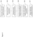
Figure 4 a summary of the encoding process according to some embodiments and the operation of theencoder 104 shown inFigure 3 is shown as a flow diagram. - The operation of generating audio frame band frequency domain representations is shown in
Figure 4 bystep 501. - The operation of determining the stereo parameters is shown in
Figure 4 bystep 502. - The operation of generating the mono (downmix) channel parameters is shown in
Figure 4 bystep 503. - The operation of quantizing the stereo (multichannel) parameters and encoding the quantized stereo (multichannel) parameters is shown in
Figure 4 bystep 504. - The operation of encoding the mono (downmix) channel parameters based on the bit usage of the optimised quantized stereo parameters is shown in
Figure 4 bystep 505. - The outputting of the encoded quantized stereo (multichannel) parameters and encoded mono (downmix) parameters/signal is shown in
Figure 4 bystep 507. - With respect to
Figure 5 anexample channel analyser 203 according to some embodiments is described in further detail. - In some embodiments the
channel analyser 203 comprises a channeldifference parameter determiner 301. The channeldifference parameter determiner 301 is configured to determine the various channel difference parameters. In the following examples the input audio signals are left and right audio signals. In some embodiments this may be generalised as j'th and j+1'th audio channels from an multichannel audio system. - For example the channel
difference parameter determiner 301 may be configured to receive the following parameters from the frame sectioner/transformer 201, -

-

- These may furthermore be represented as real and imaginary parts such as for the right channel and
-

-

- From these components the channel difference determiner may be configured to generate channel energy parameters, for example:
-

-

-

-

-

-

-


- Furthermore the channel difference determiner may be configured to determine difference (stereo) parameters according to the following equations:
-

-

-

- Furthermore in some embodiments the channel difference determiner may be configured to generate for non-speech signals further parameters such as:

- For speech signals and for the higher sub-bands the channel difference determiner may be configured to generate:


- The difference parameters such as the interchannel phase difference, the side gain and the residual prediction gain parameter values can be passed to the mono channel generator and as stereo channel parameters to the quantizer processor.
- In some embodiments the encoder 104 (or as shown in
Figure 5 , the channel analyser 203) comprises amono channel generator 305. The mono channel generator is configured to receive the channel analyser values such as the side gains and inter channel phase differences from thechannel difference determiner 301. Furthermore in some embodiments the mono channel generator/encoder 305 can be configured to further receive the input multichannel audio signals. Themono channel generator 305 can in some embodiments be configured to generate an 'aligned' or downmixed channel which is representative of the audio signals. In other words themono channel generator 305 can generate a mono (or downmixed) channel signal which represents an aligned multichannel audio signal. For example in some embodiments where there is a left channel audio signal and a right channel audio signal one of the left or right channel audio signals are delayed with respect to the other according to a determined delay difference and then the delayed channel and other channel audio signals are averaged to generate a mono channel signal. However it would be understood that in some embodiments any suitable mono channel generating method can be implemented. - The mono channel parameters/signal can then be output. In some embodiments the mono channel signal is output to the quantizer processor/
mono encoder 205 to be encoded. - With respect to
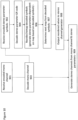
Figure 6 a summary of the analysis process (such as described inFigure 4 bysteps 502 and 503) according to some embodiments and the operation of thechannel analyser 203 shown inFigure 5 is shown as a flow diagram. - The operation of receiving the multichannel audio signal frequency components is shown in
Figure 6 bystep 551. - The operation of determining intermediate parameters (e.g. Energy parameters for the audio signal channels) is shown in
Figure 6 bystep 552. - The operation of determining the difference parameters (e.g. side gain, interphase difference, residual prediction gain) which are generated at least partially from the intermediate parameters is shown in
Figure 6 bystep 553. - The operation of generating a mono (downmix) channel signal/parameters from a stereo (multichannel) signal is shown in
Figure 6 bystep 555. - With respect to
Figure 7 an example quantizer processor/mono encoder 205 is shown in further detail. - In some embodiments the quantizer processor/
mono encoder 205 comprises ascalar quantizer 451. Thescalar quantizer 451 is configured to receive the stereo parameters from thechannel analyser 203. - The scalar quantizer can be configured to perform a scalar quantization on these values. For example the
scalar quantizer 451 can be configured to quantize the values with quantisation partition regions defined by the following array.
- The
scalar quantizer 451 can thus output an index value symbol associated with the region within the quantization partition region the level difference value occurs within. For example an initial quantisation index value output can be as follows:Input difference range -100000.0 -8.0 -5.0 -3.0 0.0 3.0 5.0 8.0 -8.0 -5.0 -3.0 -0.0 3.0 5.0 8.0 100000 Output index 0 1 2 3 4 5 6 7 - The index values can in some embodiments be output to a
remapper 453. - In some embodiments the quantizer processor/
mono encoder 205 comprises aremapper 453. Theremapper 453 can in some embodiments be configured to receive the output of thescalar quantizer 451, in other words an index value associated with the quantization partition region within which the stereo or difference parameter is found and then the map or order the index value according to a defined mapping. - In some embodiments the index (re)mapping (or reordering) is based on an adaptive map selected from a range of defined maps. The defined maps may be maps which are determined from training data or any other suitable manner which exploit intraframe correlation. For example these maps may exploit the correlation between adjacent symbols representing adjacent sub-band parameters.
- As such the first symbol within a frame may be mapped according to a default or defined map. The second symbol within a frame mapped according to a map which is selected based on the first symbol, and so on.
- For example a first symbol may be remapped according to the table
Output index 0 1 2 3 4 5 6 7 Mapped to 6 3 1 0 2 4 5 7 - The next (second) symbol may then be remapped based on a map which depends on the previous (first) symbol. For example the reordering or remapping of the second symbol may be defined as
Where previous (first) symbol =0Output index 0 1 2 3 4 5 6 7 Mapped to 7 6 4 3 1 0 2 5
Where previous (first) symbol =1Output index 0 1 2 3 4 5 6 7 Mapped to 7 6 4 3 1 0 2 5
Where previous (first) symbol =2Output index 0 1 2 3 4 5 6 7 Mapped to 7 5 3 1 0 2 4 6
Where previous (first) symbol =3Output index 0 1 2 3 4 5 6 7 Mapped to 7 5 3 1 0 2 4 6
Where previous (first) symbol =4Output index 0 1 2 3 4 5 6 7 Mapped to 7 6 4 1 0 2 3 5
Where previous (first) symbol =5Output index 0 1 2 3 4 5 6 7 Mapped 7 6 4 2 0 1 3 5 to
Where previous (first) symbol =6Output index 0 1 2 3 4 5 6 7 Mapped to 7 6 4 1 0 2 3 6
and where previous (first) symbol =7Output index 0 1 2 3 4 5 6 7 Mapped to 7 6 5 4 3 2 1 0 - These mappings may be stored as an array of mappings, such as for example
short maps[]=
 {
     7, 6, 4, 3, 1, 0, 2, 5,
     7, 6, 4, 3, 1, 0, 2, 5,
     7, 5, 3, 1, 0, 2, 4, 6,
     7, 5, 3, 1, 0, 2, 4, 6,
     7, 6, 4, 1, 0, 2, 3, 5,
     7, 6, 4, 2, 0, 1, 3, 5,
     7, 6, 4, 1, 0, 2, 3, 5,
     7, 6, 5, 4, 3, 2, 1, 0, };
Where if the previous symbol has been '0' then the first line from the above 2 dimensional array is used as map, if the previous symbol has been '1' then the second line and so on.
- the second symbol may have an array
short mapsSymbol2[]= {...}; - the third symbol may have an array
short mapsSymbol3[]= {...};
- and so on to the eighth symbol array
short mapsSymbol8[]= {...}; - where each array may be different.
| Output Symbol | Mapped Symbol | GR code 0 | GR code 1 |
| 0 | 6 | 1111110 | 11100 |
| 1 | 3 | 1110 | 101 |
| 2 | 1 | 10 | 01 |
| 3 | 0 | 0 | 00 |
| 4 | 2 | 110 | 100 |
| 5 | 4 | 11110 | 1100 |
| 6 | 5 | 1111110 | 1101 |
| 7 | 7 | 11111110 | 11101 |
- 12 side gain values that need to be transmitted, corresponding to the first 12 sub-bands;
- 5 residual prediction gains and
- 8 interchannel phase differences


For the side gain
short maps_sg[] =
 { 0, 1, 2, 3, 4, 5, 6, 7, 8, 9, 10, 11, 12, 13, 14, 15, 16,
 17, 18, 19, 20, 21, 22, 23, 24, 25, 26, 27, 28, 29, 30,
 1, 0, 2, 3, 4, 5, 6, 7, 8, 9, 10, 11, 12, 13, 14, 15, 16,
 17, 18, 19, 20, 21, 22, 23, 24, 25, 26, 27, 28, 29, 30,
 15, 4, 0, 1, 2, 3, 5, 6, 7, 8, 9, 10, 11, 12, 13, 14, 16,
 17, 18, 19, 20, 21, 22, 23, 24, 25, 26, 27, 28, 29, 30,
 12, 9, 4, 1, 0, 2, 3, 5, 6, 7, 8, 10, 11, 13, 14, 15, 16,
 17, 18, 19, 20, 21, 22, 23, 24, 25, 26, 27, 28, 29, 30,
 16, 14, 8, 4, 2, 0, 1, 3, 5, 6, 7, 9, 10, 11, 12, 13, 15,
 17, 18, 19, 20, 21, 22, 23, 24, 25, 26, 27, 28, 29, 30,
 18, 16, 14, 10, 5, 0, 1, 2, 3, 4, 6, 7, 8, 9, 11, 12, 13,
 15, 17, 19, 20, 21, 22, 23, 24, 25, 26, 27, 28, 29, 30,
 21, 19, 17, 15, 8, 4, 2, 0, 1, 3, 5, 6, 7, 9, 10, 11, 12,
 13, 14, 16, 18, 20, 22, 23, 24, 25, 26, 27, 28, 29, 30,
 21, 19, 17, 15, 12, 8, 4, 0, 1, 2, 3, 5, 6, 7, 9, 10, 11,
 13, 14, 16, 18, 20, 22, 23, 24, 25, 26, 27, 28, 29, 30,
 21, 19, 17, 15, 13, 11, 9, 3, 0, 1, 2, 4, 5, 6, 7, 8, 10,
 12, 14, 16, 18, 20, 22, 23, 24, 25, 26, 27, 28, 29, 30,
 24, 22, 20, 18, 16, 14, 12, 9, 6, 0, 1, 2, 3, 4, 5, 7, 8,
 10, 11, 13, 15, 17, 19, 21, 23, 25, 26, 27, 28, 29, 30,
 25, 23, 21, 19, 17, 15, 13, 11, 9, 6, 0, 1, 2, 3, 4, 5, 7,
 8, 10, 12, 14, 16, 18, 20, 22, 24, 26, 27, 28, 29, 30,
 27, 25, 23, 21, 19, 17, 15, 13, 11, 8, 5, 0, 1, 2, 3, 4, 6,
 7, 9, 10, 12, 14, 16, 18, 20, 22, 24, 26, 28, 29, 30,
 26, 24, 22, 20, 18, 16, 14, 12, 10, 8, 6, 4, 2, 1, 0, 3, 5,
 7, 9, 11, 13, 15, 17, 19, 21, 23, 25, 27, 28, 29, 30,
 28, 26, 24, 22, 20, 18, 16, 14, 12, 10, 8, 6, 4, 2, 0, 1, 3,
 5, 7, 9, 11, 13, 15, 17, 19, 21, 23, 25, 27, 29, 30,
 29, 27, 25, 23, 21, 19, 17, 15, 13, 11, 9, 7, 5, 3, 0, 1, 2,
 4, 6, 8, 10, 12, 14, 16, 18, 20, 22, 24, 26, 28, 30,
 30, 28, 26, 24, 22, 20, 18, 16, 14, 12, 10, 8, 6, 4, 2, 0,
 1, 3, 5, 7, 9, 11, 13, 15, 17, 19, 21, 23, 25, 27, 29,
 30, 28, 26, 24, 22, 20, 18, 16, 14, 12, 10, 8, 6, 4, 2, 1,
 0, 3, 5, 7, 9, 11, 13, 15, 17, 19, 21, 23, 25, 27, 29,
 30, 29, 27, 25, 23, 21, 19, 17, 15, 13, 11, 9, 7, 5, 3, 1,
 0, 2, 4, 6, 8, 10, 12, 14, 16, 18, 20, 22, 24, 26, 28,
 30, 29, 28, 27, 25, 23, 21, 19, 17, 15, 13, 11, 9, 7, 5, 3,
 0, 1, 2, 4, 6, 8, 10, 12, 14, 16, 18, 20, 22, 24, 26,
 30, 29, 28, 26, 24, 22, 20, 18, 16, 14, 12, 10, 9, 7, 6, 4,
 3, 2, 1, 0, 5, 8, 11, 13, 15, 17, 19, 21, 23, 25, 27,
 30, 29, 28, 27, 26, 24, 22, 20, 18, 16, 14, 12, 10, 8, 7, 5,
 4, 3, 2, 1, 0, 6, 9, 11, 13, 15, 17, 19, 21, 23, 25,
 30, 29, 28, 27, 26, 25, 23, 21, 19, 17, 15, 13, 11, 10, 8,
 7, 5, 4, 3, 2, 1, 0, 6, 9, 12, 14, 16, 18, 20, 22, 24,
 30, 29, 28, 27, 26, 25, 24, 23, 22, 20, 18, 16, 14, 12, 10,
 8, 7, 6, 5, 4, 2, 1, 0, 3, 9, 11, 13, 15, 17, 19, 21,
 30, 29, 28, 27, 26, 25, 24, 23, 22, 20, 18, 16, 14, 13, 11,
 10, 9, 7, 6, 5, 3, 2, 1, 0, 4, 8, 12, 15, 17, 19, 21,
 30, 29, 28, 27, 26, 25, 24, 23, 22, 20, 18, 16, 14, 13, 12,
 11, 10, 9, 7, 6, 5, 3, 1, 0, 2, 4, 8, 15, 17, 19, 21,
 30, 29, 28, 27, 26, 25, 24, 23, 22, 21, 20, 19, 17, 15, 13,
 12, 11, 9, 8, 7, 6, 4, 3, 2, 1, 0, 5, 10, 14, 16, 18,
 30, 29, 28, 27, 26, 25, 24, 23, 22, 21, 20, 19, 18, 17, 15,
 13, 12, 11, 10, 9, 7, 6, 5, 3, 1, 0, 2, 4, 8, 14, 16,
 30, 29, 28, 27, 26, 25, 24, 23, 22, 21, 20, 19, 18, 17, 16,
 15, 14, 13, 11, 10, 8, 7, 6, 5, 3, 2, 0, 1, 4, 9, 12,
 30, 29, 28, 27, 26, 25, 24, 23, 22, 21, 20, 19, 18, 17, 16,
 14, 13, 12, 11, 10, 9, 8, 7, 6, 5, 3, 2, 1, 0, 4, 15,
 30, 29, 28, 27, 26, 25, 24, 23, 22, 21, 20, 19, 18, 17, 16,
 15, 14, 13, 12, 11, 10, 9, 8, 7, 6, 5, 4, 3, 2, 0, 1,
 30, 29, 28, 27, 26, 25, 24, 23, 22, 21, 20, 19, 18, 17, 16,
 15, 14, 13, 12, 11, 10, 9, 8, 7, 6, 5, 4, 3, 2, 1, 0,
 };
 short maps_rpg[] = {
     0, 1, 2, 3, 4, 5, 6, 7,
     2, 0, 1, 3, 4, 5, 6, 7,
     6, 2, 0, 1, 3, 4, 5, 7,
     7, 5, 2, 0, 1, 3, 4, 6,
     7, 6, 4, 3, 1, 0, 2, 5,
     7, 6, 5, 3, 2, 1, 0, 4,
     7, 6, 5, 4, 3, 2, 0, 1,
     7, 6, 5, 4, 3, 2, 0, 1,
     6, 5, 4, 3, 1, 0, 2, 7,
 };
and for the interphase differences
 short maps_ipd[]=
 {
     7, 6, 4, 3, 1, 0, 2, 5,
     7, 6, 4, 3, 1, 0, 2, 5,
     7, 5, 3, 1, 0, 2, 4, 6,
     7, 5, 3, 1, 0, 2, 4, 6,
     7, 6, 4, 1, 0, 2, 3, 5,
     7, 6, 4, 2, 0, 1, 3, 5,
     7, 6, 4, 1, 0, 2, 3, 5,
     7, 6, 5, 4, 3, 2, 1, 0,
     6, 5, 4, 2, 0, 1, 3, 7
 };
 short sg_data1[] = {1,0,2,
 4, 0, 1, 2, 3, 5, 6, 7, 8, 9, 10, 11, 12, 13, 14,
 9, 4, 1, 0, 2, 3, 5, 6, 7, 8, 10, 11,
 8, 4, 2, 0, 1, 3, 5, 6, 7, 9, 10, 11, 12, 13,
 10, 5, 0, 1, 2, 3, 4, 6, 7, 8, 9, 11, 12, 13,
 8, 4, 2, 0, 1, 3, 5, 6, 7, 9, 10, 11, 12, 13, 14,
 12, 8, 4, 0, 1, 2, 3, 5, 6, 7, 9, 10, 11, 13, 14,
 3, 0, 1, 2, 4, 5, 6, 7, 8,
 9, 6, 0, 1, 2, 3, 4, 5, 7, 8, 10, 11,
 6, 0, 1, 2, 3, 4, 5, 7, 8,
 8, 5, 0, 1, 2, 3, 4, 6, 7, 9, 10,
 2, 1, 0, 3,
 0, 1,
 0, 1, 2,
 0};
 short sg_data2[] =
 {3,3,
 15,16,
 12, 13,
 14, 16,
 14, 17,
 15, 19,
 15, 19,
 9, 16,
 12, 19,
 9, 18,
 11,20,
 4, 16,
 2, 16,
 3, 17,
 1, 16};
16, 14, 8, 4, 2, 0, 1, 3, 5, 6, 7, 9, 10, 11, 12, 13, 15, 17, 18, 19, 20, 21, 22, 23, 24, 25, 26, 27, 28, 29, 30,


- (a) hardware-only circuit implementations (such as implementations in only analog and/or digital circuitry) and
- (b) to combinations of circuits and software (and/or firmware), such as: (i) to a combination of processor(s) or (ii) to portions of processor(s)/software (including digital signal processor(s)), software, and memory(ies) that work together to cause an apparatus, such as a mobile phone or server, to perform various functions and
- (c) to circuits, such as a microprocessor(s) or a portion of a microprocessor(s), that require software or firmware for operation, even if the software or firmware is not physically present.
Claims (14)
- An apparatus comprising:means for receiving at least two audio channel signals;means for determining (301), for a first frame, at least two parameters representing a difference between the at least two channel audio signals;means for scalar quantising (451) the at least two parameters to generate at least two index values;means for determining an initial index map for reordering one of the at least two index values, and means for determining at least one further index map for reordering at least one further of the at least two index values, wherein the at least one further index map is determined based on the one of the at least two index values;means for reordering the one of the at least two index values based on the initial index map;means for reordering the further of the at least two index values based on the at least one further index map;means for entropy encoding the reordered one of the at least two index values based on an order position of the reordered one of the at least two index values;means for entropy encoding the reordered further of the at least two index values based on an order position of the reordered further of the at least two index values;means for generating a single channel representation (305) of the at least two audio channel signals dependent on the at least two parameters; andmeans for encoding (456) the single channel representation.
- The apparatus as claimed in claim 1, wherein the means for scalar quantising further comprises ordering the scalar quantized output according to a predetermined map.
- The apparatus as claimed in any of claims 1 to 2, wherein the means for entropy encoding the reordered one and further index values based on an order position of the reordered index one and further index values comprises means (455) for applying a Golomb-Rice encoding to the reordered one and further index values based on an order position of the reordered index one and further index values.
- The apparatus as claimed in any of claims 1 to 3, wherein the means for determining, for a first frame, at least two parameters comprises means for determining at least three parameters;the means for scalar quantising (451) the at least two parameters comprises means for scalar quantising the at least three parameters to generate at least three index values, the at least three index values comprising a first index value, a first further index value and a second further index value; andthe means for determining at least one further index map comprises:means for determining a first further index map for reordering the first further index value, wherein the first further index map is determined dependent on the first index value; andmeans for determining a second further index map for reordering the second further index value, wherein the second further index map is determined dependent on the first further index value.
- The apparatus as claimed in claim 4, wherein the means for determining the first further index map for reordering the first further index value comprises means for selecting, from a first array of index maps, the first further index map based on the first index value.
- The apparatus as claimed in claim 5, wherein the means for determining the second further index map for reordering the second further index value comprises means for selecting, from a second array of index maps, the second further index map based on the first further index value.
- The apparatus as claimed in claim 6, wherein the second array of index maps is the first array of index maps.
- The apparatus as claimed in any of claims 1 to 4, wherein the means for determining the at least one further index map for reordering at least one further of the at least two index values comprises means for selecting, from an array of index maps, the at least one further index map based on the one of the at least two index values.
- The apparatus as claimed in claim 8, wherein the means for determining the at least one further index map for reordering at least one further of the at least two index values comprises means for generating, from a compressed array of index maps, the at least one further index map based on the one of the at least two index values.
- An apparatus comprising:means for entropy decoding (803) from a first part of a signal at least two parameter index values, wherein the parameters represent a difference between at least two channel audio signals, and wherein the signal is an encoded multichannel audio signal;means for reordering a first of the at least two parameter index values based on a first determined reordering to generate a first reordered index value;means for reordering a second of the at least two parameter index values based on a second determined reordering to generate a second reordered index value, wherein the second determined reordering is based on the first reordered index value;means for dequantizing the first and the second reordered index value to generate the at least two parameters;means for receiving from a further part of the signal an encoded single channel representation signal;means for determining a number of bits used in the first part of the signal;means for decoding the encoded single channel representation signal based on the number of bits used in the first part of the signal; andmeans for generating the multichannel audio signal based on applying the at least two parameters to the decoded encoded single channel representation signal to generate a second channel.
- The apparatus as claimed in claim 10, wherein the means for reordering a first of the at least two parameter index values based on a first determined reordering to generate a first reordered index value comprises:means for determining an inverse ordering; andmeans for applying the inverse ordering.
- The apparatus as claimed in claim 11, wherein the means for reordering a second of the at least two parameter index values based on a first determined reordering to generate a first reordered index value comprises:means for determining a second inverse ordering based on the first reordered index value; andmeans for applying the second inverse ordering.
- A method comprising:receiving at least two audio channel signals;determining (502), for a first frame, at least two parameters representing a difference between the at least two channel audio signals;scalar quantising (703) the at least two parameters to generate at least two index values;determining an initial index map for reordering one of the at least two index values, and determining (704) at least one further index map for reordering at least one further of the at least two index values, wherein the at least one further index map is determined based on the one of the at least two index values;reordering (705) the one of the at least two index values based on the initial index map;reordering (705) the further of the at least two index values based on the at least one further index map;entropy encoding (707) the reordered one of the at least two index values based on an order position of the reordered one of the at least two index values;entropy encoding (707) the reordered further of the at least two index values based on an order position of the reordered further of the at least two index values;generating a single channel representation (503) of the at least two audio channel signals dependent on the at least two parameters; andencoding (505) the single channel representation.
- A method comprising:entropy decoding (904) from a first part of a signal at least two parameter index values, wherein the parameters represent a difference between at least two channel audio signals, and wherein the signal is an encoded multichannel audio signal;reordering a first of the at least two parameter index values based on a first determined reordering to generate a first reordered index value;reordering a second of the at least two parameter index values based on a second determined reordering to generate a second reordered index value, wherein the second determined reordering is based on the first reordered index value;dequantizing the first and the second reordered index value to generate the at least two parameters.receiving (901) from a further part of the signal an encoded mono channel signal;determining a number of bits used in the first part of the signal;decoding (903) the encoded mono channel signal based on the number of bits used in the first part of the signal; andgenerating (909) the multichannel audio signal based on applying the at least two parameters to the decoded encoded mono channel to generate a second channel.
Applications Claiming Priority (2)
| Application Number | Priority Date | Filing Date | Title |
|---|---|---|---|
| GB1701594.2A GB2559199A (en) | 2017-01-31 | 2017-01-31 | Stereo audio signal encoder |
| PCT/FI2018/050018 WO2018142018A1 (en) | 2017-01-31 | 2018-01-11 | Stereo audio signal encoder |
Publications (3)
| Publication Number | Publication Date |
|---|---|
| EP3577649A1 EP3577649A1 (en) | 2019-12-11 |
| EP3577649A4 EP3577649A4 (en) | 2020-11-11 |
| EP3577649B1 true EP3577649B1 (en) | 2023-05-10 |
Family
ID=58462846
Family Applications (1)
| Application Number | Title | Priority Date | Filing Date |
|---|---|---|---|
| EP18747600.7A Active EP3577649B1 (en) | 2017-01-31 | 2018-01-11 | Stereo audio signal encoder |
Country Status (4)
| Country | Link |
|---|---|
| EP (1) | EP3577649B1 (en) |
| ES (1) | ES2946235T3 (en) |
| GB (1) | GB2559199A (en) |
| WO (1) | WO2018142018A1 (en) |
Families Citing this family (2)
| Publication number | Priority date | Publication date | Assignee | Title |
|---|---|---|---|---|
| WO2018086947A1 (en) * | 2016-11-08 | 2018-05-17 | Fraunhofer-Gesellschaft zur Förderung der angewandten Forschung e.V. | Apparatus and method for encoding or decoding a multichannel signal using a side gain and a residual gain |
| GB2580899A (en) * | 2019-01-22 | 2020-08-05 | Nokia Technologies Oy | Audio representation and associated rendering |
Family Cites Families (8)
| Publication number | Priority date | Publication date | Assignee | Title |
|---|---|---|---|---|
| AU2003281128A1 (en) * | 2002-07-16 | 2004-02-02 | Koninklijke Philips Electronics N.V. | Audio coding |
| US7433824B2 (en) * | 2002-09-04 | 2008-10-07 | Microsoft Corporation | Entropy coding by adapting coding between level and run-length/level modes |
| PL3300076T3 (en) * | 2008-07-11 | 2019-11-29 | Fraunhofer Ges Forschung | Audio encoder and audio decoder |
| WO2013179084A1 (en) * | 2012-05-29 | 2013-12-05 | Nokia Corporation | Stereo audio signal encoder |
| WO2013185857A1 (en) * | 2012-06-14 | 2013-12-19 | Telefonaktiebolaget L M Ericsson (Publ) | Method and arrangement for scalable low-complexity coding/decoding |
| EP2875510A4 (en) * | 2012-07-19 | 2016-04-13 | Nokia Technologies Oy | Stereo audio signal encoder |
| EP3014609B1 (en) * | 2013-06-27 | 2017-09-27 | Dolby Laboratories Licensing Corporation | Bitstream syntax for spatial voice coding |
| TWI579831B (en) * | 2013-09-12 | 2017-04-21 | 杜比國際公司 | Method for quantization of parameters, method for dequantization of quantized parameters and computer-readable medium, audio encoder, audio decoder and audio system thereof |
-
2017
- 2017-01-31 GB GB1701594.2A patent/GB2559199A/en not_active Withdrawn
-
2018
- 2018-01-11 ES ES18747600T patent/ES2946235T3/en active Active
- 2018-01-11 EP EP18747600.7A patent/EP3577649B1/en active Active
- 2018-01-11 WO PCT/FI2018/050018 patent/WO2018142018A1/en unknown
Also Published As
| Publication number | Publication date |
|---|---|
| ES2946235T3 (en) | 2023-07-14 |
| GB2559199A (en) | 2018-08-01 |
| EP3577649A4 (en) | 2020-11-11 |
| GB201701594D0 (en) | 2017-03-15 |
| WO2018142018A1 (en) | 2018-08-09 |
| EP3577649A1 (en) | 2019-12-11 |
Similar Documents
| Publication | Publication Date | Title |
|---|---|---|
| EP3120354B1 (en) | Methods, apparatuses for forming audio signal payload and audio signal payload | |
| EP2856776B1 (en) | Stereo audio signal encoder | |
| US9280976B2 (en) | Audio signal encoder | |
| US9865269B2 (en) | Stereo audio signal encoder | |
| US7610195B2 (en) | Decoding of predictively coded data using buffer adaptation | |
| US10199044B2 (en) | Audio signal encoder comprising a multi-channel parameter selector | |
| EP4365896A2 (en) | Determination of spatial audio parameter encoding and associated decoding | |
| US10770081B2 (en) | Stereo audio signal encoder | |
| EP3577649B1 (en) | Stereo audio signal encoder | |
| US20160111100A1 (en) | Audio signal encoder | |
| WO2017148526A1 (en) | Audio signal encoder, audio signal decoder, method for encoding and method for decoding | |
| Chen et al. | Scalefactor based bit shift FGS audio coding |
Legal Events
| Date | Code | Title | Description |
|---|---|---|---|
| STAA | Information on the status of an ep patent application or granted ep patent |
Free format text: STATUS: THE INTERNATIONAL PUBLICATION HAS BEEN MADE |
|
| PUAI | Public reference made under article 153(3) epc to a published international application that has entered the european phase |
Free format text: ORIGINAL CODE: 0009012 |
|
| STAA | Information on the status of an ep patent application or granted ep patent |
Free format text: STATUS: REQUEST FOR EXAMINATION WAS MADE |
|
| 17P | Request for examination filed |
Effective date: 20190902 |
|
| AK | Designated contracting states |
Kind code of ref document: A1 Designated state(s): AL AT BE BG CH CY CZ DE DK EE ES FI FR GB GR HR HU IE IS IT LI LT LU LV MC MK MT NL NO PL PT RO RS SE SI SK SM TR |
|
| AX | Request for extension of the european patent |
Extension state: BA ME |
|
| DAV | Request for validation of the european patent (deleted) | ||
| DAX | Request for extension of the european patent (deleted) | ||
| A4 | Supplementary search report drawn up and despatched |
Effective date: 20201014 |
|
| RIC1 | Information provided on ipc code assigned before grant |
Ipc: G10L 19/008 20130101AFI20201008BHEP Ipc: G10L 19/035 20130101ALN20201008BHEP Ipc: H03M 7/40 20060101ALI20201008BHEP Ipc: G10L 19/02 20130101ALI20201008BHEP |
|
| REG | Reference to a national code |
Ref country code: DE Ref legal event code: R079 Ref document number: 602018049621 Country of ref document: DE Free format text: PREVIOUS MAIN CLASS: G10L0019035000 Ipc: G10L0019008000 |
|
| GRAP | Despatch of communication of intention to grant a patent |
Free format text: ORIGINAL CODE: EPIDOSNIGR1 |
|
| STAA | Information on the status of an ep patent application or granted ep patent |
Free format text: STATUS: GRANT OF PATENT IS INTENDED |
|
| RIC1 | Information provided on ipc code assigned before grant |
Ipc: G10L 19/035 20130101ALN20221108BHEP Ipc: G10L 19/00 20130101ALI20221108BHEP Ipc: H03M 7/40 20060101ALI20221108BHEP Ipc: G10L 19/008 20130101AFI20221108BHEP |
|
| INTG | Intention to grant announced |
Effective date: 20221205 |
|
| RIC1 | Information provided on ipc code assigned before grant |
Ipc: G10L 19/035 20130101ALN20221125BHEP Ipc: G10L 19/00 20130101ALI20221125BHEP Ipc: H03M 7/40 20060101ALI20221125BHEP Ipc: G10L 19/008 20130101AFI20221125BHEP |
|
| GRAS | Grant fee paid |
Free format text: ORIGINAL CODE: EPIDOSNIGR3 |
|
| GRAA | (expected) grant |
Free format text: ORIGINAL CODE: 0009210 |
|
| STAA | Information on the status of an ep patent application or granted ep patent |
Free format text: STATUS: THE PATENT HAS BEEN GRANTED |
|
| AK | Designated contracting states |
Kind code of ref document: B1 Designated state(s): AL AT BE BG CH CY CZ DE DK EE ES FI FR GB GR HR HU IE IS IT LI LT LU LV MC MK MT NL NO PL PT RO RS SE SI SK SM TR |
|
| REG | Reference to a national code |
Ref country code: GB Ref legal event code: FG4D |
|
| REG | Reference to a national code |
Ref country code: AT Ref legal event code: REF Ref document number: 1567528 Country of ref document: AT Kind code of ref document: T Effective date: 20230515 Ref country code: CH Ref legal event code: EP |
|
| REG | Reference to a national code |
Ref country code: DE Ref legal event code: R096 Ref document number: 602018049621 Country of ref document: DE |
|
| REG | Reference to a national code |
Ref country code: IE Ref legal event code: FG4D |
|
| REG | Reference to a national code |
Ref country code: NL Ref legal event code: FP |
|
| REG | Reference to a national code |
Ref country code: SE Ref legal event code: TRGR |
|
| REG | Reference to a national code |
Ref country code: ES Ref legal event code: FG2A Ref document number: 2946235 Country of ref document: ES Kind code of ref document: T3 Effective date: 20230714 |
|
| REG | Reference to a national code |
Ref country code: LT Ref legal event code: MG9D |
|
| REG | Reference to a national code |
Ref country code: AT Ref legal event code: MK05 Ref document number: 1567528 Country of ref document: AT Kind code of ref document: T Effective date: 20230510 |
|
| PG25 | Lapsed in a contracting state [announced via postgrant information from national office to epo] |
Ref country code: PT Free format text: LAPSE BECAUSE OF FAILURE TO SUBMIT A TRANSLATION OF THE DESCRIPTION OR TO PAY THE FEE WITHIN THE PRESCRIBED TIME-LIMIT Effective date: 20230911 Ref country code: NO Free format text: LAPSE BECAUSE OF FAILURE TO SUBMIT A TRANSLATION OF THE DESCRIPTION OR TO PAY THE FEE WITHIN THE PRESCRIBED TIME-LIMIT Effective date: 20230810 Ref country code: AT Free format text: LAPSE BECAUSE OF FAILURE TO SUBMIT A TRANSLATION OF THE DESCRIPTION OR TO PAY THE FEE WITHIN THE PRESCRIBED TIME-LIMIT Effective date: 20230510 |
|
| PG25 | Lapsed in a contracting state [announced via postgrant information from national office to epo] |
Ref country code: RS Free format text: LAPSE BECAUSE OF FAILURE TO SUBMIT A TRANSLATION OF THE DESCRIPTION OR TO PAY THE FEE WITHIN THE PRESCRIBED TIME-LIMIT Effective date: 20230510 Ref country code: PL Free format text: LAPSE BECAUSE OF FAILURE TO SUBMIT A TRANSLATION OF THE DESCRIPTION OR TO PAY THE FEE WITHIN THE PRESCRIBED TIME-LIMIT Effective date: 20230510 Ref country code: LV Free format text: LAPSE BECAUSE OF FAILURE TO SUBMIT A TRANSLATION OF THE DESCRIPTION OR TO PAY THE FEE WITHIN THE PRESCRIBED TIME-LIMIT Effective date: 20230510 Ref country code: LT Free format text: LAPSE BECAUSE OF FAILURE TO SUBMIT A TRANSLATION OF THE DESCRIPTION OR TO PAY THE FEE WITHIN THE PRESCRIBED TIME-LIMIT Effective date: 20230510 Ref country code: IS Free format text: LAPSE BECAUSE OF FAILURE TO SUBMIT A TRANSLATION OF THE DESCRIPTION OR TO PAY THE FEE WITHIN THE PRESCRIBED TIME-LIMIT Effective date: 20230910 Ref country code: HR Free format text: LAPSE BECAUSE OF FAILURE TO SUBMIT A TRANSLATION OF THE DESCRIPTION OR TO PAY THE FEE WITHIN THE PRESCRIBED TIME-LIMIT Effective date: 20230510 Ref country code: GR Free format text: LAPSE BECAUSE OF FAILURE TO SUBMIT A TRANSLATION OF THE DESCRIPTION OR TO PAY THE FEE WITHIN THE PRESCRIBED TIME-LIMIT Effective date: 20230811 |
|
| PG25 | Lapsed in a contracting state [announced via postgrant information from national office to epo] |
Ref country code: FI Free format text: LAPSE BECAUSE OF FAILURE TO SUBMIT A TRANSLATION OF THE DESCRIPTION OR TO PAY THE FEE WITHIN THE PRESCRIBED TIME-LIMIT Effective date: 20230510 |
|
| PG25 | Lapsed in a contracting state [announced via postgrant information from national office to epo] |
Ref country code: SK Free format text: LAPSE BECAUSE OF FAILURE TO SUBMIT A TRANSLATION OF THE DESCRIPTION OR TO PAY THE FEE WITHIN THE PRESCRIBED TIME-LIMIT Effective date: 20230510 |
|
| PGFP | Annual fee paid to national office [announced via postgrant information from national office to epo] |
Ref country code: GB Payment date: 20231130 Year of fee payment: 7 |
|
| PG25 | Lapsed in a contracting state [announced via postgrant information from national office to epo] |
Ref country code: SM Free format text: LAPSE BECAUSE OF FAILURE TO SUBMIT A TRANSLATION OF THE DESCRIPTION OR TO PAY THE FEE WITHIN THE PRESCRIBED TIME-LIMIT Effective date: 20230510 Ref country code: SK Free format text: LAPSE BECAUSE OF FAILURE TO SUBMIT A TRANSLATION OF THE DESCRIPTION OR TO PAY THE FEE WITHIN THE PRESCRIBED TIME-LIMIT Effective date: 20230510 Ref country code: RO Free format text: LAPSE BECAUSE OF FAILURE TO SUBMIT A TRANSLATION OF THE DESCRIPTION OR TO PAY THE FEE WITHIN THE PRESCRIBED TIME-LIMIT Effective date: 20230510 Ref country code: EE Free format text: LAPSE BECAUSE OF FAILURE TO SUBMIT A TRANSLATION OF THE DESCRIPTION OR TO PAY THE FEE WITHIN THE PRESCRIBED TIME-LIMIT Effective date: 20230510 Ref country code: DK Free format text: LAPSE BECAUSE OF FAILURE TO SUBMIT A TRANSLATION OF THE DESCRIPTION OR TO PAY THE FEE WITHIN THE PRESCRIBED TIME-LIMIT Effective date: 20230510 Ref country code: CZ Free format text: LAPSE BECAUSE OF FAILURE TO SUBMIT A TRANSLATION OF THE DESCRIPTION OR TO PAY THE FEE WITHIN THE PRESCRIBED TIME-LIMIT Effective date: 20230510 |
|
| PGFP | Annual fee paid to national office [announced via postgrant information from national office to epo] |
Ref country code: SE Payment date: 20231213 Year of fee payment: 7 Ref country code: NL Payment date: 20231215 Year of fee payment: 7 Ref country code: FR Payment date: 20231212 Year of fee payment: 7 |
|
| REG | Reference to a national code |
Ref country code: DE Ref legal event code: R097 Ref document number: 602018049621 Country of ref document: DE |
|
| PLBE | No opposition filed within time limit |
Free format text: ORIGINAL CODE: 0009261 |
|
| STAA | Information on the status of an ep patent application or granted ep patent |
Free format text: STATUS: NO OPPOSITION FILED WITHIN TIME LIMIT |
|
| PGFP | Annual fee paid to national office [announced via postgrant information from national office to epo] |
Ref country code: ES Payment date: 20240206 Year of fee payment: 7 |
|
| 26N | No opposition filed |
Effective date: 20240213 |
|
| PGFP | Annual fee paid to national office [announced via postgrant information from national office to epo] |
Ref country code: DE Payment date: 20231205 Year of fee payment: 7 |
|
| PG25 | Lapsed in a contracting state [announced via postgrant information from national office to epo] |
Ref country code: SI Free format text: LAPSE BECAUSE OF FAILURE TO SUBMIT A TRANSLATION OF THE DESCRIPTION OR TO PAY THE FEE WITHIN THE PRESCRIBED TIME-LIMIT Effective date: 20230510 |