EP3575581A1 - Method for controlling a control valve - Google Patents
Method for controlling a control valve Download PDFInfo
- Publication number
- EP3575581A1 EP3575581A1 EP19176067.7A EP19176067A EP3575581A1 EP 3575581 A1 EP3575581 A1 EP 3575581A1 EP 19176067 A EP19176067 A EP 19176067A EP 3575581 A1 EP3575581 A1 EP 3575581A1
- Authority
- EP
- European Patent Office
- Prior art keywords
- control valve
- fluid
- fuel
- density
- determined
- Prior art date
- Legal status (The legal status is an assumption and is not a legal conclusion. Google has not performed a legal analysis and makes no representation as to the accuracy of the status listed.)
- Granted
Links
- 238000000034 method Methods 0.000 title claims abstract description 42
- 239000012530 fluid Substances 0.000 claims abstract description 45
- 238000011144 upstream manufacturing Methods 0.000 claims abstract description 14
- 230000001105 regulatory effect Effects 0.000 claims abstract description 7
- 230000001276 controlling effect Effects 0.000 claims abstract description 6
- 239000000446 fuel Substances 0.000 claims description 51
- 238000002485 combustion reaction Methods 0.000 claims description 39
- 238000009423 ventilation Methods 0.000 description 9
- 239000000203 mixture Substances 0.000 description 6
- OKTJSMMVPCPJKN-UHFFFAOYSA-N Carbon Chemical compound [C] OKTJSMMVPCPJKN-UHFFFAOYSA-N 0.000 description 4
- 230000001419 dependent effect Effects 0.000 description 3
- 238000005259 measurement Methods 0.000 description 3
- 238000010926 purge Methods 0.000 description 2
- 239000003463 adsorbent Substances 0.000 description 1
- TZCXTZWJZNENPQ-UHFFFAOYSA-L barium sulfate Chemical compound [Ba+2].[O-]S([O-])(=O)=O TZCXTZWJZNENPQ-UHFFFAOYSA-L 0.000 description 1
- 238000009530 blood pressure measurement Methods 0.000 description 1
- 230000001955 cumulated effect Effects 0.000 description 1
- 238000001514 detection method Methods 0.000 description 1
- 238000011161 development Methods 0.000 description 1
- 230000018109 developmental process Effects 0.000 description 1
- 238000010586 diagram Methods 0.000 description 1
- 230000000977 initiatory effect Effects 0.000 description 1
- 239000007788 liquid Substances 0.000 description 1
- 238000012545 processing Methods 0.000 description 1
- 239000000523 sample Substances 0.000 description 1
- 230000002000 scavenging effect Effects 0.000 description 1
- 230000001953 sensory effect Effects 0.000 description 1
- 230000007704 transition Effects 0.000 description 1
- 238000013022 venting Methods 0.000 description 1
Images
Classifications
-
- F—MECHANICAL ENGINEERING; LIGHTING; HEATING; WEAPONS; BLASTING
- F02—COMBUSTION ENGINES; HOT-GAS OR COMBUSTION-PRODUCT ENGINE PLANTS
- F02D—CONTROLLING COMBUSTION ENGINES
- F02D41/00—Electrical control of supply of combustible mixture or its constituents
- F02D41/0025—Controlling engines characterised by use of non-liquid fuels, pluralities of fuels, or non-fuel substances added to the combustible mixtures
- F02D41/003—Adding fuel vapours, e.g. drawn from engine fuel reservoir
- F02D41/0042—Controlling the combustible mixture as a function of the canister purging, e.g. control of injected fuel to compensate for deviation of air fuel ratio when purging
-
- F—MECHANICAL ENGINEERING; LIGHTING; HEATING; WEAPONS; BLASTING
- F02—COMBUSTION ENGINES; HOT-GAS OR COMBUSTION-PRODUCT ENGINE PLANTS
- F02M—SUPPLYING COMBUSTION ENGINES IN GENERAL WITH COMBUSTIBLE MIXTURES OR CONSTITUENTS THEREOF
- F02M25/00—Engine-pertinent apparatus for adding non-fuel substances or small quantities of secondary fuel to combustion-air, main fuel or fuel-air mixture
- F02M25/08—Engine-pertinent apparatus for adding non-fuel substances or small quantities of secondary fuel to combustion-air, main fuel or fuel-air mixture adding fuel vapours drawn from engine fuel reservoir
- F02M25/0836—Arrangement of valves controlling the admission of fuel vapour to an engine, e.g. valve being disposed between fuel tank or absorption canister and intake manifold
-
- F—MECHANICAL ENGINEERING; LIGHTING; HEATING; WEAPONS; BLASTING
- F02—COMBUSTION ENGINES; HOT-GAS OR COMBUSTION-PRODUCT ENGINE PLANTS
- F02D—CONTROLLING COMBUSTION ENGINES
- F02D41/00—Electrical control of supply of combustible mixture or its constituents
- F02D41/0025—Controlling engines characterised by use of non-liquid fuels, pluralities of fuels, or non-fuel substances added to the combustible mixtures
- F02D41/003—Adding fuel vapours, e.g. drawn from engine fuel reservoir
- F02D41/0032—Controlling the purging of the canister as a function of the engine operating conditions
- F02D41/004—Control of the valve or purge actuator, e.g. duty cycle, closed loop control of position
-
- F—MECHANICAL ENGINEERING; LIGHTING; HEATING; WEAPONS; BLASTING
- F02—COMBUSTION ENGINES; HOT-GAS OR COMBUSTION-PRODUCT ENGINE PLANTS
- F02D—CONTROLLING COMBUSTION ENGINES
- F02D41/00—Electrical control of supply of combustible mixture or its constituents
- F02D41/0025—Controlling engines characterised by use of non-liquid fuels, pluralities of fuels, or non-fuel substances added to the combustible mixtures
- F02D41/003—Adding fuel vapours, e.g. drawn from engine fuel reservoir
- F02D41/0045—Estimating, calculating or determining the purging rate, amount, flow or concentration
-
- F—MECHANICAL ENGINEERING; LIGHTING; HEATING; WEAPONS; BLASTING
- F02—COMBUSTION ENGINES; HOT-GAS OR COMBUSTION-PRODUCT ENGINE PLANTS
- F02D—CONTROLLING COMBUSTION ENGINES
- F02D41/00—Electrical control of supply of combustible mixture or its constituents
- F02D41/02—Circuit arrangements for generating control signals
- F02D41/04—Introducing corrections for particular operating conditions
-
- F—MECHANICAL ENGINEERING; LIGHTING; HEATING; WEAPONS; BLASTING
- F02—COMBUSTION ENGINES; HOT-GAS OR COMBUSTION-PRODUCT ENGINE PLANTS
- F02M—SUPPLYING COMBUSTION ENGINES IN GENERAL WITH COMBUSTIBLE MIXTURES OR CONSTITUENTS THEREOF
- F02M25/00—Engine-pertinent apparatus for adding non-fuel substances or small quantities of secondary fuel to combustion-air, main fuel or fuel-air mixture
- F02M25/08—Engine-pertinent apparatus for adding non-fuel substances or small quantities of secondary fuel to combustion-air, main fuel or fuel-air mixture adding fuel vapours drawn from engine fuel reservoir
- F02M25/089—Layout of the fuel vapour installation
-
- F—MECHANICAL ENGINEERING; LIGHTING; HEATING; WEAPONS; BLASTING
- F02—COMBUSTION ENGINES; HOT-GAS OR COMBUSTION-PRODUCT ENGINE PLANTS
- F02D—CONTROLLING COMBUSTION ENGINES
- F02D2200/00—Input parameters for engine control
- F02D2200/02—Input parameters for engine control the parameters being related to the engine
- F02D2200/06—Fuel or fuel supply system parameters
- F02D2200/0602—Fuel pressure
-
- F—MECHANICAL ENGINEERING; LIGHTING; HEATING; WEAPONS; BLASTING
- F02—COMBUSTION ENGINES; HOT-GAS OR COMBUSTION-PRODUCT ENGINE PLANTS
- F02D—CONTROLLING COMBUSTION ENGINES
- F02D2200/00—Input parameters for engine control
- F02D2200/02—Input parameters for engine control the parameters being related to the engine
- F02D2200/06—Fuel or fuel supply system parameters
- F02D2200/0606—Fuel temperature
Definitions
- the invention relates to a method for controlling a control valve, in particular a control valve of a tank ventilation system, preferably the tank ventilation system of a motor vehicle.
- Control valves in tank ventilation systems regulate a volume flow from a filter (an adsorbent) of a tank towards a suction pipe (or a connecting path between the filter and at least one combustion chamber) of an internal combustion engine.
- the filter is regularly an activated carbon filter which binds the components of the fluid (eg a fuel) stored in the tank, which have been degassed from the tank.
- the activated carbon filter can be fluidly connected to the intake manifold of the internal combustion engine via the control valve, so that the fluid bound or temporarily stored in the filter can be supplied to the combustion chamber in a regulated manner.
- the determination of the tank ventilation system supplied amount is currently z. B. allows via lambda probes.
- the control valve of the tank ventilation system is opened slowly and the deviation from a setpoint for lambda (fuel-air ratio, is determined by exhaust gas sensors) is monitored. It is assumed that this deviation results exclusively from the supply of fuel from the tank ventilation system.
- a signal downstream of the combustion chamber is evaluated, ie it must first occur a deviation from the desired value for lambda before a control can take place. This results in an increase in raw emissions. Further, all the mixture deviations are returned to the fuel supplied from the tank venting system.
- the calculated fuel fraction does not correspond to the actual fuel fraction.
- the tank ventilation must be very carefully controlled or severely limited so as not to produce too great an impact on the smoothness and the raw emissions of the internal combustion engine.
- the object of the present invention is at least partially to solve the problems mentioned with reference to the prior art.
- a method for controlling a control valve is to be proposed by which a more accurate control of the combustion chamber supplied proportion of fuel is made possible.
- the control valve regulates in particular a volume flow along a connecting path between the filter and the internal combustion engine. Possibly. the connection path is connected to the intake manifold via a discharge point.
- steps a) to c) are carried out in the order described.
- steps a) and b) are performed at least temporarily parallel to one another.
- the step c) takes place in particular taking into account the pressure curve, that is preferably temporally after step b).
- step b at least one minimum and one maximum of the pressure profile are detected in step b).
- a minimum of the pressure curve is detected, which is present in the pressure curve immediately before the closing of the control valve.
- a maximum of the pressure curve is detected, which is present in the pressure curve immediately after the closing of the control valve.
- Closing the control valve comprises, in particular, that in the closed state of the control valve, no volume flow can flow via the control valve.
- the measuring of the pressure curve is effected in particular by a continuous or intermittent sensory detection of a pressure condition. Concrete sensor readings can be cumulated. Single values of the pressure measurement can be averaged and / or stored.
- the pressure profile can be characterized or analyzed using the following pressure parameters: maximum values, minimum values, deviations from measured or predefinable measurement or threshold values, rate of change.
- the determination of the density of the fluid can be carried out on the basis of measured pressure states or pressure parameters derived therefrom, optionally with the inclusion of one of the abovementioned pressure parameters.
- the determination The density of the fluid can be determined in particular by evaluating (at least) the minimum and maximum of the pressure profile.
- the volumetric flow of the fluid flowing via the at least partially opened control valve can be determined (for example, detected by measurement via a hot-film sensor or the like).
- the volume flow can be determined immediately before initiating the closing operation according to step a).
- the volume flow can be determined in the process of opening the control valve following the closing operation in accordance with step a). The volume flow is detected in particular by measurement.
- At least a first portion of a first component of the fluid and a second portion of a second component of the fluid can be determined.
- the first component is air and the second component is a fuel.
- the fuel is at least partially, in particular completely gaseous. Possibly. the fuel may be present as a liquid.
- a temperature of the fluid can be determined. Knowing the temperature determines the density of the fluid (with a higher accuracy). In particular, the temperature is measured together with the pressure, z. B. by a combined sensor (pressure / temperature sensor).
- the control valve is clocked in particular with at least one frequency or opens and closes in frequency.
- a pulsed volume flow of the fluid can thus be provided via the control valve.
- the method in particular at least steps a) to c), optionally additionally at least one of steps i) and ii) (or both) is carried out at least in two, three, four or more consecutive closing operations, in particular during each closing operation.
- the density determined according to step c) can be verified by repeatedly performing the method. Possibly. it is possible to average the values determined for the density.
- the frequency is in particular between 5 and 50 hertz, preferably between 5 and 20 hertz.
- the control valve is controlled in particular by means of a (PWM) signal (pulse width modulation), whereby, in particular, a successive opening of the control valve occurs at a certain duty cycle.
- PWM pulse width modulation
- a volumetric flow flowing via the control valve can be controlled via the duty cycle.
- a control of a fuel addition of the internal combustion engine is performed depending on the specific density of the fluid.
- determining the density of the fuel fraction can be determined in the fluid, so that a more precise addition of a predetermined amount of fuel is possible via the controlled opening of the control valve.
- the pressure sensor is arranged between the filter and the control valve.
- the control valve is in particular designed so that a pulsed volume flow is passed through the control valve to the suction line.
- the control valve is controlled via a PWM signal.
- the density of the fluid can be determined. From the principle known single density values (density of the fuel used, and density of the air, possibly temperature-dependent determined) and the (total) density of the fluid, the proportions of air and fuel can be determined.
- the proportion of the fuel or the proportion of the fuel originating from the filter can be determined, this proportion being determined already upstream of the combustion chamber.
- the fuel addition of the internal combustion engine can be regulated before the combustion of the fuel.
- the determination of the density in the said frequency can be carried out, so that abrupt and / or surge-like changes in the composition of the fluid can be determined and these changes taking into account regulating the fuel addition can take place.
- an accuracy of the determination of the fuel fraction in the fluid is independent of a quality of the mixture precontrol.
- a motor vehicle at least comprising an internal combustion engine with at least one combustion chamber, a tank for a convertible in the internal combustion engine fuel with a filter, a suction tube, via which at least air and the fuel can be supplied to the combustion chamber, a control valve that a at least the fuel comprehensive Volume flow from the filter to the suction pipe (along the line, in particular the first line and the second line) regulates or according to the underlying control circuit controls and a pressure sensor for measuring a pressure profile upstream of the control valve.
- the control valve is openable and openable by a control unit.
- the control unit is designed or carried out for carrying out the method already described. The control unit can thus carry out the described method or execute it during operation of the motor vehicle.
- the method can also be used in internal combustion engines that are not used in motor vehicles.
- the method can also be used if portions of the fluid are to be generally determined in gas-carrying lines.
- the fluid does not need to be supplied to an internal combustion engine.
- the method can also be executed by a computer or with a processor of a control unit.
- a data processing system comprising a processor adapted / configured to perform the method or part of the steps of the proposed method.
- a computer-readable storage medium may be provided that includes instructions that, when executed by a computer / processor, cause it to perform the method or at least part of the steps of the proposed method.
- inventively determined density of the fluid comprising air and fuel for (direct or indirect) control proposed a fuel quantity addition to an internal combustion engine.
- Other particularly advantageous uses and possible uses of the determined fuel-air mixture for controlling the combustion processes, in particular in motor vehicles, will be apparent from the further explanations of the method specified here.
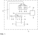
- Fig. 1 shows a motor vehicle 11.
- the motor vehicle 11 includes an internal combustion engine 7 with a plurality of combustion chambers 12, a tank 5 for a convertible in the internal combustion engine 7 fuel 10 with a filter 4, a suction pipe 6, on the at least air and the fuel 10 toward Combustion chamber 12 can be supplied, and a control valve 1, which comprises a at least the fuel 10 comprehensive volume flow 2 of the fluid 3 from the filter 4 via the lines 16, 17 to the suction pipe 4 controls.
- the control valve 1 can be controlled by a control unit 14 for opening and closing.
- the control unit 14 is designed or carried out for carrying out the method.
- the motor vehicle 11 further comprises a pressure sensor 13 immediately upstream of the control valve 1, via which the pressure 18 and the pressure curve 9 upstream of the control valve 1 can be measured.
- the fuel 10 is stored in a tank 5, wherein fuel vapors can reach the filter 4 via the first line 16.
- the temporarily stored in the filter 4 fuel 10 is transferred via the control valve 1 and via the second line 17 to the intake manifold 6.
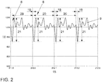
- Fig. 2 shows an embodiment of the method in a diagram.
- On the vertical axis of the pressure 18 is applied, which is measured via the pressure sensor 13 (immediately) upstream of the control valve 1.
- the time 15 is plotted on the horizontal axis.
- step a) a closing operation 8 of the control valve 1 is performed.
- step b) the pressure curve 9 upstream of the control valve 1 is measured.
- step c) a density of the fluid 3 is determined.
- the control valve 1 is clocked with a frequency and opens and closes in frequency (here, the frequency is 10 hertz).
- the method is performed here at four consecutive closing operations 8.
- a flow of the fluid 3 is formed. If the control valve 1 then closes (closing operation 8, transition to the closed phase 20), the volume flow 2 of the fluid 3 is interrupted abruptly. This leads to a measurable increase in pressure upstream of the control valve 1.
- the course of the pressure rise (ie the pressure curve 9) or the pressure change (or the measured pressure difference 21) depends on the flow velocity of the volume flow 2 during the open phase 19 and from the density of the fluid 3 from.
- the illustrated vibration of the pressure curve 9 represents the pressure change upstream of the control valve 1, which is caused by the closing operation 8.
- the density of the fluid 3 can be determined.
- the proportions of air and fuel 10 can be determined from the basically known single density values (density of the used fuel 10, and density of the air, possibly temperature-dependent) and the determined (total) density of the fluid 3.
- the proportion of the fuel 10 or the proportion of the fuel 10 originating from the filter 4 can be determined, this proportion being determined already upstream of the combustion chamber 12.
- the fuel addition of the internal combustion engine 7 can be regulated even before the combustion of the fuel 10.
Landscapes
- Engineering & Computer Science (AREA)
- Chemical & Material Sciences (AREA)
- Combustion & Propulsion (AREA)
- Mechanical Engineering (AREA)
- General Engineering & Computer Science (AREA)
- Electrical Control Of Air Or Fuel Supplied To Internal-Combustion Engine (AREA)
- Supplying Secondary Fuel Or The Like To Fuel, Air Or Fuel-Air Mixtures (AREA)
Abstract
Verfahren zur Ansteuerung eines Regelventils (1), wobei das Regelventil (1) einen Volumenstrom (2) eines Fluids (3) entlang einer Leitung (16, 17) regelt; wobei das Verfahren zumindest die folgenden Schritte umfasst:a) Durchführen eines Schließvorganges (8) des Regelventils (1);b) Messen eines Druckverlaufs (9) stromaufwärts des Regelventils (1);c) Bestimmen einer Dichte des Fluids (3).Method for controlling a control valve (1), the control valve (1) regulating a volume flow (2) of a fluid (3) along a line (16, 17); the method comprising at least the following steps: a) performing a closing process (8) of the control valve (1); b) measuring a pressure profile (9) upstream of the control valve (1); c) determining a density of the fluid (3).
Description
Die Erfindung betrifft ein Verfahren zur Ansteuerung eines Regelventils, insbesondere eines Regelventils eines Tankentlüftungssystems, bevorzugt das Tankentlüftungssystem eines Kraftfahrzeuges.The invention relates to a method for controlling a control valve, in particular a control valve of a tank ventilation system, preferably the tank ventilation system of a motor vehicle.
Regelventile in Tankentlüftungssystemen regeln einen Volumenstrom von einem Filter (einem Adsorptionsmittel) eines Tanks hin zu einem Saugrohr (bzw. einer Verbindungsstrecke zwischen Filter und mindestens einer Brennkammer) einer Verbrennungskraftmaschine.Control valves in tank ventilation systems regulate a volume flow from a filter (an adsorbent) of a tank towards a suction pipe (or a connecting path between the filter and at least one combustion chamber) of an internal combustion engine.
Der Filter ist regelmäßig ein Aktivkohlefilter, der die aus dem Tank ausgegasten Bestandteile des in dem Tank gelagerten Fluids (z. B. ein Kraftstoff) bindet. Der Aktivkohlefilter ist mit dem Saugrohr der Verbrennungskraftmaschine fluidtechnisch über das Regelventil verbindbar, so dass das in dem Filter gebundene bzw. zwischengespeicherte Fluid der Brennkammer geregelt zuführbar ist.The filter is regularly an activated carbon filter which binds the components of the fluid (eg a fuel) stored in the tank, which have been degassed from the tank. The activated carbon filter can be fluidly connected to the intake manifold of the internal combustion engine via the control valve, so that the fluid bound or temporarily stored in the filter can be supplied to the combustion chamber in a regulated manner.
Für die Berechnung der einzuspritzenden Kraftstoffmenge ist es erforderlich, die Menge des durch das Tankentlüftungssystem zugeführten Kraftstoffes zu kennen.For the calculation of the amount of fuel to be injected, it is necessary to know the amount of fuel supplied by the tank ventilation system.
Die Bestimmung der über das Tankentlüftungssystem zugeführten Menge wird bisher z. B. über Lambdasonden ermöglicht. Dazu wird das Regelventil des Tankentlüftungssystems langsam geöffnet und die Abweichung von einem Sollwert für Lambda (Kraftstoff-Luft Verhältnis; wird bestimmt über Abgassensorik) überwacht. Es wird dabei angenommen, dass diese Abweichung ausschließlich aus der Zuführung von Kraftstoff aus dem Tankentlüftungssystem resultiert. Dafür wird jedoch ein Signal stromabwärts des Brennraums ausgewertet, d. h. es muss zunächst eine Abweichung von dem Sollwert für Lambda auftreten, bevor eine Regelung erfolgen kann. Dies hat eine Steigerung der Rohemissionen zur Folge. Weiter werden sämtliche Gemischabweichungen auf den aus dem Tankentlüftungssystem zugeführten Kraftstoff zurückgeführt. Bei einer ungenauen Gemischvorsteuerung (und einer Abweichung von einem Sollwert für das Gemisch) entspricht der berechnete Kraftstoffanteil nicht dem wirklichen Kraftstoffanteil. Daraus resultierend muss die Tankentlüftung sehr vorsichtig gesteuert bzw. stark begrenzt werden, um keine zu großen Auswirkungen auf die Laufruhe und die Rohemissionen der Verbrennungskraftmaschine zu erzeugen.The determination of the tank ventilation system supplied amount is currently z. B. allows via lambda probes. For this purpose, the control valve of the tank ventilation system is opened slowly and the deviation from a setpoint for lambda (fuel-air ratio, is determined by exhaust gas sensors) is monitored. It is assumed that this deviation results exclusively from the supply of fuel from the tank ventilation system. For this purpose, however, a signal downstream of the combustion chamber is evaluated, ie it must first occur a deviation from the desired value for lambda before a control can take place. This results in an increase in raw emissions. Further, all the mixture deviations are returned to the fuel supplied from the tank venting system. In the case of an inaccurate mixture pilot control (and a deviation from a target value for the mixture), the calculated fuel fraction does not correspond to the actual fuel fraction. As a result, the tank ventilation must be very carefully controlled or severely limited so as not to produce too great an impact on the smoothness and the raw emissions of the internal combustion engine.
Aus der
Aufgabe der vorliegenden Erfindung ist es, die mit Bezug auf den Stand der Technik angeführten Probleme zumindest teilweise zu lösen. Insbesondere soll ein Verfahren zur Ansteuerung eines Regelventils vorgeschlagen werden, durch das eine genauere Regelung des der Brennkammer zugeführten Anteils an Kraftstoff ermöglicht wird.The object of the present invention is at least partially to solve the problems mentioned with reference to the prior art. In particular, a method for controlling a control valve is to be proposed by which a more accurate control of the combustion chamber supplied proportion of fuel is made possible.
Zur Lösung dieser Aufgaben trägt ein Verfahren mit den Merkmalen gemäß Patentanspruch 1 bei. Vorteilhafte Weiterbildungen sind Gegenstand der abhängigen Patentansprüche. Die in den Patentansprüchen einzeln aufgeführten Merkmale sind in technologisch sinnvoller Weise miteinander kombinierbar und können durch erläuternde Sachverhalte aus der Beschreibung und/oder Details aus den Figuren ergänzt werden, wobei weitere Ausführungsvarianten der Erfindung aufgezeigt werden.To solve these problems, a method with the features according to
Es wird ein Verfahren zur Ansteuerung eines Regelventils vorgeschlagen, wobei das Regelventil einen Volumenstrom eines Fluids entlang einer Leitung (erste Leitung, zweite Leitung; also durch die Leitung), insbesondere von einem Filter eines Tanks zu einem Saugrohr einer Verbrennungskraftmaschine, regelt. Das Verfahren weist zumindest die folgenden Schritte auf:
- a) Durchführen eines Schließvorganges des Regelventils; und
- b) Messen eines Druckverlaufs stromaufwärts des Regelventils;
- c) Bestimmen einer Dichte (Masse pro Volumen, also [Kilogramm/Kubikmeter]) des Fluids.
- a) performing a closing operation of the control valve; and
- b) measuring a pressure profile upstream of the control valve;
- c) Determining a density (mass per volume, ie [kilogram / cubic meter]) of the fluid.
Das Regelventil regelt insbesondere einen Volumenstrom entlang einer Verbindungsstrecke zwischen Filter und Verbrennungskraftmaschine. Ggf. ist die Verbindungsstrecke mit dem Saugrohr über eine Einleitstelle verbunden.The control valve regulates in particular a volume flow along a connecting path between the filter and the internal combustion engine. Possibly. the connection path is connected to the intake manifold via a discharge point.
Insbesondere werden die Schritte a) bis c) in der beschriebenen Reihenfolge durchgeführt. Insbesondere werden die Schritte a) und b) zumindest zeitweise parallel zueinander durchgeführt. Der Schritt c) erfolgt insbesondere unter Berücksichtigung des Druckverlaufs, also bevorzugt zeitlich nach Schritt b).In particular, steps a) to c) are carried out in the order described. In particular, steps a) and b) are performed at least temporarily parallel to one another. The step c) takes place in particular taking into account the pressure curve, that is preferably temporally after step b).
Insbesondere werden in Schritt b) zumindest ein Minimum und ein Maximum des Druckverlaufs erfasst. Insbesondere wird ein Minimum des Druckverlaufs erfasst, das im Druckverlauf unmittelbar vor dem Schließen des Regelventils vorliegt. Insbesondere wird ein Maximum des Druckverlaufs erfasst, das im Druckverlauf unmittelbar nach dem Schließen des Regelventils vorliegt.In particular, at least one minimum and one maximum of the pressure profile are detected in step b). In particular, a minimum of the pressure curve is detected, which is present in the pressure curve immediately before the closing of the control valve. In particular, a maximum of the pressure curve is detected, which is present in the pressure curve immediately after the closing of the control valve.
Ein Schließen des Regelventils umfasst insbesondere, dass im geschlossenen Zustand des Regelventils gerade kein Volumenstrom über das Regelventil strömen kann.Closing the control valve comprises, in particular, that in the closed state of the control valve, no volume flow can flow via the control valve.
Das Messen des Druckverlaufs erfolgt insbesondere durch ein kontinuierliches oder intermittierendes sensorisches Erfassen eines Druckzustandes. Konkrete Sensormesswerte können kumuliert werden. Einzelwerte der Druckmessung können gemittelt und/oder gespeichert werden. Der Druckverlauf kann anhand folgender Druckparameter charakterisiert oder analysiert werden: Maximumwerte, Minimumwerte, Abweichungen von gemessenen oder vorgebbaren Mess- oder Schwellwerten, Änderungsgeschwindigkeit.The measuring of the pressure curve is effected in particular by a continuous or intermittent sensory detection of a pressure condition. Concrete sensor readings can be cumulated. Single values of the pressure measurement can be averaged and / or stored. The pressure profile can be characterized or analyzed using the following pressure parameters: maximum values, minimum values, deviations from measured or predefinable measurement or threshold values, rate of change.
Die Bestimmung der Dichte des Fluids kann rechnerisch auf Basis gemessener Druckzustände oder davon abgeleiteten Druckparameter erfolgen, gegebenenfalls unter Einbezug eines der vorstehend genannten Druckparameter. Die Bestimmung der Dichte des Fluids kann insbesondere durch Auswertung (zumindest) von Minimum und Maximum des Druckverlaufs bestimmt werden.The determination of the density of the fluid can be carried out on the basis of measured pressure states or pressure parameters derived therefrom, optionally with the inclusion of one of the abovementioned pressure parameters. The determination The density of the fluid can be determined in particular by evaluating (at least) the minimum and maximum of the pressure profile.
Insbesondere kann in einem weiteren Schritt i) der über das zumindest teilweise geöffnete Regelventil strömende Volumenstrom des Fluids ermittelt werden (z. B. über einen Heißfilmsensor oder ähnliches messtechnisch erfasst). Insbesondere kann der Volumenstrom unmittelbar vor Einleiten des Schließvorganges gemäß Schritt a) ermittelt werden. Insbesondere kann der Volumenstrom bei dem auf den Schließvorgang gemäß Schritt a) folgenden Vorgang des Öffnens des Regelventils ermittelt werden. Der Volumenstrom wird insbesondere messtechnisch erfasst.In particular, in a further step i), the volumetric flow of the fluid flowing via the at least partially opened control valve can be determined (for example, detected by measurement via a hot-film sensor or the like). In particular, the volume flow can be determined immediately before initiating the closing operation according to step a). In particular, the volume flow can be determined in the process of opening the control valve following the closing operation in accordance with step a). The volume flow is detected in particular by measurement.
In Kenntnis von Dichte und Volumenstrom kann zumindest ein erster Anteil eines ersten Bestandteils des Fluids und ein zweiter Anteil eines zweiten Bestandteils des Fluids ermittelt werden.With knowledge of density and volume flow, at least a first portion of a first component of the fluid and a second portion of a second component of the fluid can be determined.
Insbesondere ist der erste Bestandteil Luft und der zweite Bestandteil ein Kraftstoff. Der Kraftstoff liegt zumindest teilweise, insbesondere vollständig gasförmig vor. Ggf. kann der Kraftstoff als Flüssigkeit vorliegen.In particular, the first component is air and the second component is a fuel. The fuel is at least partially, in particular completely gaseous. Possibly. the fuel may be present as a liquid.
In einem weiteren Schritt ii) kann eine Temperatur des Fluids ermittelt werden. In Kenntnis der Temperatur wird die Dichte des Fluids (mit einer höheren Genauigkeit) bestimmt. Insbesondere wird die Temperatur gemeinsam mit dem Druck gemessen, z. B. durch einen kombinierten Sensor (Druck-/ Temperatursensor).In a further step ii), a temperature of the fluid can be determined. Knowing the temperature determines the density of the fluid (with a higher accuracy). In particular, the temperature is measured together with the pressure, z. B. by a combined sensor (pressure / temperature sensor).
Das Regelventil wird insbesondere mit zumindest einer Frequenz getaktet bzw. öffnet und schließt in der Frequenz. Insbesondere kann so über das Regelventil ein gepulster Volumenstrom des Fluids bereitgestellt werden.The control valve is clocked in particular with at least one frequency or opens and closes in frequency. In particular, a pulsed volume flow of the fluid can thus be provided via the control valve.
Das Verfahren, insbesondere zumindest die Schritte a) bis c), ggf. zusätzlich zumindest einer der Schritte i) und ii) (oder jeweils beide) wird zumindest bei zwei, drei, vier oder mehr aufeinanderfolgenden Schließvorgängen durchgeführt, insbesondere bei jedem Schließvorgang.The method, in particular at least steps a) to c), optionally additionally at least one of steps i) and ii) (or both) is carried out at least in two, three, four or more consecutive closing operations, in particular during each closing operation.
Insbesondere kann die gemäß Schritt c) ermittelte Dichte über eine wiederholte Durchführung des Verfahrens verifiziert werden. Ggf. ist eine Mittelung der ermittelten Werte für die Dichte möglich.In particular, the density determined according to step c) can be verified by repeatedly performing the method. Possibly. it is possible to average the values determined for the density.
Die Frequenz beträgt insbesondere zwischen 5 und 50 Hertz, bevorzugt zwischen 5 und 20 Hertz.The frequency is in particular between 5 and 50 hertz, preferably between 5 and 20 hertz.
Das Regelventil wird insbesondere über ein (PWM-)Signal (Pulsweitenmodulation) angesteuert, wobei ab einem bestimmten Tastverhältnis ein insbesondere sukzessives Öffnen des Regelventils erfolgt. Über das Tastverhältnis kann insbesondere ein über das Regelventil strömender Volumenstrom gesteuert werden.The control valve is controlled in particular by means of a (PWM) signal (pulse width modulation), whereby, in particular, a successive opening of the control valve occurs at a certain duty cycle. In particular, a volumetric flow flowing via the control valve can be controlled via the duty cycle.
Insbesondere wird in Abhängigkeit von der bestimmten Dichte des Fluids eine Regelung einer Kraftstoffzugabe der Verbrennungskraftmaschine durchgeführt.In particular, a control of a fuel addition of the internal combustion engine is performed depending on the specific density of the fluid.
Über die Bestimmung der Dichte kann der Kraftstoffanteil im Fluid ermittelt werden, so dass über die gesteuerte Öffnung des Regelventils eine genauere Zugabe einer vorgebbaren Kraftstoffmenge möglich ist.By determining the density of the fuel fraction can be determined in the fluid, so that a more precise addition of a predetermined amount of fuel is possible via the controlled opening of the control valve.
Insbesondere ist der Drucksensor zwischen dem Filter und dem Regelventil angeordnet.In particular, the pressure sensor is arranged between the filter and the control valve.
Das Regelventil ist insbesondere so ausgeführt, dass ein gepulster Volumenstrom über das Regelventil hin zur Saugleitung geführt wird. Insbesondere wird das Regelventil über ein PWM-Signal angesteuert.The control valve is in particular designed so that a pulsed volume flow is passed through the control valve to the suction line. In particular, the control valve is controlled via a PWM signal.
Während der Offen-Phase des Regelventils bildet sich eine Strömung des Fluids aus. Schließt das Regelventil dann, wird der Volumenstrom des Fluids schlagartig unterbrochen. Dies führt zu einem messbaren Druckanstieg stromaufwärts des Regelventils. Der Verlauf des Druckanstiegs bzw. der Druckänderung hängt insbesondere von der Strömungsgeschwindigkeit des Volumenstroms während der Offen-Phase und von der Dichte des Fluids ab.During the open phase of the control valve, a flow of the fluid is formed. If the control valve then closes, the volume flow of the fluid is interrupted abruptly. This leads to a measurable increase in pressure upstream of the control valve. The course of the pressure increase or the pressure change depends in particular on the flow velocity of the volume flow during the open phase and on the density of the fluid.
Mit dem Drucksensor bzw. unter zusätzlicher Bestimmung der Temperatur kann die Dichte des Fluids bestimmt werden. Aus den grundsätzlich bekannten Einzeldichtewerten (Dichte des verwendeten Kraftstoffs, und Dichte der Luft, ggf. temperaturabhängig bestimmt) und der (Gesamt-)Dichte des Fluids können die Anteile von Luft und Kraftstoff bestimmt werden.With the pressure sensor or with additional determination of the temperature, the density of the fluid can be determined. From the principle known single density values (density of the fuel used, and density of the air, possibly temperature-dependent determined) and the (total) density of the fluid, the proportions of air and fuel can be determined.
Mit dem beschriebenen Verfahren kann der Anteil des Kraftstoffes, bzw. der aus dem Filter stammende Anteil des Kraftstoffes bestimmt werden, wobei dieser Anteil bereits stromaufwärts der Brennkammer ermittelt wird. Damit kann die Kraftstoffzugabe der Verbrennungskraftmaschine bereits vor der Verbrennung des Kraftstoffes geregelt werden.With the method described, the proportion of the fuel or the proportion of the fuel originating from the filter can be determined, this proportion being determined already upstream of the combustion chamber. Thus, the fuel addition of the internal combustion engine can be regulated before the combustion of the fuel.
Insbesondere kann die Bestimmung der Dichte in der genannten Frequenz erfolgen, so dass auch schlagartige und/oder schwallartige Änderungen der Zusammensetzung des Fluids bestimmbar sind und eine diese Änderungen berücksichtigende Regelung der Kraftstoffzugabe erfolgen kann.In particular, the determination of the density in the said frequency can be carried out, so that abrupt and / or surge-like changes in the composition of the fluid can be determined and these changes taking into account regulating the fuel addition can take place.
Weiter ist eine Genauigkeit der Bestimmung des Kraftstoffanteils im Fluid unabhängig von einer Qualität der Gemischvorsteuerung.Furthermore, an accuracy of the determination of the fuel fraction in the fluid is independent of a quality of the mixture precontrol.
Es ist somit möglich, die Kraftstoffzugabe vor der Verbrennung des Kraftstoffes zu regeln, so dass Rohemissionen gesenkt werden können.It is thus possible to control the fuel addition before the combustion of the fuel, so that raw emissions can be reduced.
Weiter ist ein schnelles Ansteuern der Tankentlüftung (bzw. ein schnelles Öffnen des Regelventils) möglich, so dass eine Erhöhung der Spülluftmenge erreicht werden kann. Die Erhöhung der Spülluftmenge führt dazu, dass der in dem Filter gespeicherte Kraftstoff besser aus dem Filter abgeführt werden kann.Furthermore, a fast triggering of the tank ventilation (or a rapid opening of the control valve) is possible, so that an increase in the amount of purging air can be achieved. The increase in the purge air volume causes the fuel stored in the filter can be better removed from the filter.
Es wird weiter ein Kraftfahrzeug vorgeschlagen, zumindest aufweisend eine Verbrennungskraftmaschine mit mindestens einer Brennkammer, einen Tank für einen in der Verbrennungskraftmaschine umsetzbaren Kraftstoff mit einem Filter, ein Saugrohr, über das zumindest Luft und der Kraftstoff hin zur Brennkammer zuführbar sind, ein Regelventil, dass einen zumindest den Kraftstoff umfassenden Volumenstrom von dem Filter zu dem Saugrohr (entlang der Leitung, insbesondere der ersten Leitung und der zweiten Leitung) regelt bzw. gemäß dem zugrunde liegenden Regelkreis steuert sowie einen Drucksensor zur Messung eines Druckverlaufs stromaufwärts des Regelventils. Das Regelventil ist zum Öffnen und Schließen von einer Steuereinheit ansteuerbar. Die Steuereinheit ist zur Durchführung des bereits beschriebenen Verfahrens eingerichtet bzw. geeignet ausgeführt. Die Steuereinheit kann das beschriebene Verfahren also ausführen bzw. führt es im Betrieb des Kraftfahrzeuges aus.It is further proposed a motor vehicle, at least comprising an internal combustion engine with at least one combustion chamber, a tank for a convertible in the internal combustion engine fuel with a filter, a suction tube, via which at least air and the fuel can be supplied to the combustion chamber, a control valve that a at least the fuel comprehensive Volume flow from the filter to the suction pipe (along the line, in particular the first line and the second line) regulates or according to the underlying control circuit controls and a pressure sensor for measuring a pressure profile upstream of the control valve. The control valve is openable and openable by a control unit. The control unit is designed or carried out for carrying out the method already described. The control unit can thus carry out the described method or execute it during operation of the motor vehicle.
Insbesondere kann das Verfahren auch bei Verbrennungskraftmaschinen eingesetzt werden, die nicht in Kraftfahrzeugen eingesetzt sind.In particular, the method can also be used in internal combustion engines that are not used in motor vehicles.
Das Verfahren kann auch eingesetzt werden, wenn Anteile des Fluids allgemein in gasführenden Leitungen bestimmt werden sollen. Dazu muss das Fluid keiner Verbrennungskraftmaschine zugeführt werden.The method can also be used if portions of the fluid are to be generally determined in gas-carrying lines. For this purpose, the fluid does not need to be supplied to an internal combustion engine.
Weiter kann das Verfahren auch von einem Computer bzw. mit einem Prozessor einer Steuereinheit ausgeführt werden.Furthermore, the method can also be executed by a computer or with a processor of a control unit.
Es wird demnach auch ein System zur Datenverarbeitung vorgeschlagen, das einen Prozessor umfasst, der so angepasst/konfiguriert ist, dass er das Verfahren bzw. einen Teil der Schritte des vorgeschlagenen Verfahrens ausführt.Accordingly, there is also proposed a data processing system comprising a processor adapted / configured to perform the method or part of the steps of the proposed method.
Es kann ein computerlesbares Speichermedium vorgesehen sein, das Befehle umfasst, die bei der Ausführung durch einen Computer/Prozessor diesen veranlassen, das Verfahren bzw. mindestens einen Teil der Schritte des vorgeschlagenen Verfahrens auszuführen.A computer-readable storage medium may be provided that includes instructions that, when executed by a computer / processor, cause it to perform the method or at least part of the steps of the proposed method.
Die Ausführungen zu dem Verfahren sind insbesondere auf das Kraftfahrzeug oder das computerimplementierte Verfahren übertragbar und umgekehrt.The statements relating to the method are transferable in particular to the motor vehicle or the computer-implemented method, and vice versa.
Zudem wird noch eine Verwendung der erfindungsgemäß bestimmten Dichte des Fluids umfassend Luft und Kraftstoff zur (direkten oder mittelbaren) Regelung einer Kraftstoffmengenzugabe hin zu einer Verbrennungskraftmaschine vorgeschlagen. Weitere besonders vorteilhafte Verwendungen und Einsatzmöglichkeiten des ermittelten Kraftstoff-Luft-Gemisches zur Regelung der Verbrennungsvorgänge, insbesondere bei Kraftfahrzeugen, ergeben sich aus den weiteren Erläuterungen zum hier angegebenen Verfahren.In addition, a use of the inventively determined density of the fluid comprising air and fuel for (direct or indirect) control proposed a fuel quantity addition to an internal combustion engine. Other particularly advantageous uses and possible uses of the determined fuel-air mixture for controlling the combustion processes, in particular in motor vehicles, will be apparent from the further explanations of the method specified here.
Vorsorglich sei angemerkt, dass die hier verwendeten Zahlwörter ("erste", "zweite", ...) vorrangig (nur) zur Unterscheidung von mehreren gleichartigen Gegenständen, Größen oder Prozessen dienen, also insbesondere keine Abhängigkeit und/oder Reihenfolge dieser Gegenstände, Größen oder Prozesse zueinander zwingend vorgeben. Sollte eine Abhängigkeit und/oder Reihenfolge erforderlich sein, ist dies hier explizit angegeben oder es ergibt sich offensichtlich für den Fachmann beim Studium der konkret beschriebenen Ausgestaltung.By way of precaution, it should be noted that the numerical terms used here ("first", "second",...) Primarily (only) serve to distinguish a plurality of similar objects, variables or processes, ie in particular no dependence and / or order of these objects, quantities or mandate processes to one another. If a dependency and / or order are required, this is explicitly stated here or it obviously results for the person skilled in the art when studying the concretely described embodiment.
Die Erfindung sowie das technische Umfeld werden nachfolgend anhand der beiliegenden Figuren näher erläutert. Es ist darauf hinzuweisen, dass die Erfindung durch die angeführten Ausführungsbeispiele nicht beschränkt werden soll. Insbesondere ist es, soweit nicht explizit anders dargestellt, auch möglich, Teilaspekte der in den Figuren erläuterten Sachverhalte zu extrahieren und mit anderen Bestandteilen und Erkenntnissen aus der vorliegenden Beschreibung zu kombinieren. Insbesondere ist darauf hinzuweisen, dass die Figuren und insbesondere die dargestellten Größenverhältnisse nur schematisch sind. Es zeigen:
- Fig. 1:
- ein Kraftfahrzeug; und
- Fig. 2:
- eine Ausführungsvariante des Verfahrens.
- Fig. 1:
- a motor vehicle; and
- Fig. 2:
- an embodiment of the method.
Das Kraftfahrzeug 11 umfasst weiter einen Drucksensor 13 unmittelbar stromaufwärts des Regelventils 1, über den der Druck 18 bzw. der Druckverlauf 9 stromaufwärts des Regelventils 1 messbar ist.The
Der Kraftstoff 10 wird in einem Tank 5 gelagert, wobei Kraftstoffdämpfe über die erste Leitung 16 in den Filter 4 gelangen können. Der im Filter 4 zwischengespeicherte Kraftstoff 10 wird über das Regelventil 1 und über die zweite Leitung 17 zum Saugrohr 6 überführt.The
Gemäß Schritt a) wird ein Schließvorgang 8 des Regelventils 1 durchgeführt. Gemäß Schritt b) wird der Druckverlauf 9 stromaufwärts des Regelventils 1 gemessen. Gemäß Schritt c) wird eine Dichte des Fluids 3 bestimmt.According to step a), a
Das Regelventil 1 wird mit einer Frequenz getaktet und öffnet und schließt in der Frequenz (hier beträgt die Frequenz 10 Hertz). Das Verfahren wird hier bei vier aufeinanderfolgenden Schließvorgängen 8 durchgeführt.The
Während der Offen-Phase 19 des Regelventils 1 bildet sich eine Strömung des Fluids 3 aus. Schließt das Regelventil 1 dann (Schließvorgang 8, Übergang zur geschlossenen Phase 20), wird der Volumenstrom 2 des Fluids 3 schlagartig unterbrochen. Dies führt zu einem messbaren Druckanstieg stromaufwärts des Regelventils 1. Der Verlauf des Druckanstiegs (also der Druckverlauf 9) bzw. die Druckänderung (bzw. die gemessene Druckdifferenz 21) hängt von der Strömungsgeschwindigkeit des Volumenstroms 2 während der Offen-Phase 19 und von der Dichte des Fluids 3 ab. Die abgebildete Schwingung des Druckverlaufs 9 stellt die Druckänderung stromaufwärts des Regelventils 1 dar, die durch den Schließvorgang 8 hervorgerufen wird.During the
Mit dem Drucksensor 13 bzw. unter zusätzlicher Bestimmung der Temperatur kann die Dichte des Fluids 3 bestimmt werden. Aus den grundsätzlich bekannten Einzeldichtewerten (Dichte des verwendeten Kraftstoffs 10, und Dichte der Luft, ggf. temperaturabhängig bestimmt) und der ermittelten (Gesamt-)Dichte des Fluids 3 können die Anteile von Luft und Kraftstoff 10 bestimmt werden.With the
Mit dem beschriebenen Verfahren kann der Anteil des Kraftstoffes 10, bzw. der aus dem Filter 4 stammende Anteil des Kraftstoffes 10 bestimmt werden, wobei dieser Anteil bereits stromaufwärts der Brennkammer 12 ermittelt wird. Damit kann die Kraftstoffzugabe der Verbrennungskraftmaschine 7 bereits vor der Verbrennung des Kraftstoffes 10 geregelt werden.With the method described, the proportion of the
- 11
- Regelventilcontrol valve
- 22
- Volumenstromflow
- 33
- Fluidfluid
- 44
- Filterfilter
- 55
- Tanktank
- 66
- Saugrohrsuction tube
- 77
- VerbrennungskraftmaschineInternal combustion engine
- 88th
- Schließvorgangclosing
- 99
- Druckverlaufpressure curve
- 1010
- Kraftstofffuel
- 1111
- Kraftfahrzeugmotor vehicle
- 1212
- Brennkammercombustion chamber
- 1313
- Drucksensorpressure sensor
- 1414
- Steuereinheitcontrol unit
- 1515
- ZeitTime
- 1616
- erste Leitungfirst line
- 1717
- zweite Leitungsecond line
- 1818
- Druckpressure
- 1919
- Offen-PhaseOpen phase
- 2020
- Geschlossen-PhaseClosed phase
- 2121
- Druckdifferenzpressure difference
Claims (10)
Applications Claiming Priority (1)
| Application Number | Priority Date | Filing Date | Title |
|---|---|---|---|
| DE102018112731.6A DE102018112731A1 (en) | 2018-05-28 | 2018-05-28 | Method for controlling a control valve |
Publications (2)
| Publication Number | Publication Date |
|---|---|
| EP3575581A1 true EP3575581A1 (en) | 2019-12-04 |
| EP3575581B1 EP3575581B1 (en) | 2021-07-07 |
Family
ID=66647049
Family Applications (1)
| Application Number | Title | Priority Date | Filing Date |
|---|---|---|---|
| EP19176067.7A Active EP3575581B1 (en) | 2018-05-28 | 2019-05-23 | Method for controlling a control valve |
Country Status (4)
| Country | Link |
|---|---|
| US (1) | US11261829B2 (en) |
| EP (1) | EP3575581B1 (en) |
| CN (1) | CN110541768B (en) |
| DE (1) | DE102018112731A1 (en) |
Families Citing this family (1)
| Publication number | Priority date | Publication date | Assignee | Title |
|---|---|---|---|---|
| AU2015376127B2 (en) * | 2015-01-07 | 2019-10-17 | Norgren Limited | Dual filter for moisture removal from a fluid flow |
Citations (4)
| Publication number | Priority date | Publication date | Assignee | Title |
|---|---|---|---|---|
| EP0533405A1 (en) * | 1991-09-16 | 1993-03-24 | Ford Motor Company Limited | An internal combustion engine |
| US20070251509A1 (en) * | 2006-04-26 | 2007-11-01 | Denso Corporation | Air-fuel ratio control apparatus of internal combustion engine |
| WO2012049219A1 (en) | 2010-10-14 | 2012-04-19 | Continental Automotive Gmbh | Method and apparatus for operating a tank ventilation system |
| DE102015117050A1 (en) * | 2014-10-31 | 2016-05-04 | GM Global Technology Operations LLC (n. d. Ges. d. Staates Delaware) | A system and method for controlling the amount of purge fluid supplied to a cylinder of an engine based on an operating parameter of a purge pump |
Family Cites Families (57)
| Publication number | Priority date | Publication date | Assignee | Title |
|---|---|---|---|---|
| DE3737822A1 (en) * | 1987-11-06 | 1989-05-18 | Schatz Oskar | CHARGING METHOD FOR OPERATING AN INTERNAL COMBUSTION ENGINE AND COMBUSTION ENGINE FOR IMPLEMENTING THE METHOD |
| DE3813220C2 (en) * | 1988-04-20 | 1997-03-20 | Bosch Gmbh Robert | Method and device for setting a tank ventilation valve |
| JPH04292542A (en) * | 1991-03-19 | 1992-10-16 | Honda Motor Co Ltd | Device for measuring component of air-fuel mixture to be sucked by internal combustion engine and air/fuel ratio control device for internal combustion engine |
| US5363832A (en) * | 1992-05-14 | 1994-11-15 | Nippondenso Co., Ltd. | Fuel vapor purging control system with air/fuel ratio compensating system for internal combustion engine |
| JPH06101534A (en) * | 1992-09-21 | 1994-04-12 | Nissan Motor Co Ltd | Device for processing evaporative fuel of engine |
| JPH0835452A (en) * | 1994-07-26 | 1996-02-06 | Hitachi Ltd | Diagnostic method for evaporation purge system |
| US5746187A (en) * | 1995-08-11 | 1998-05-05 | Mazda Motor Corporation | Automotive engine control system |
| DE19958465C2 (en) * | 1999-12-04 | 2001-12-06 | Bosch Gmbh Robert | Method for operating an internal combustion engine |
| JP4400003B2 (en) * | 2001-04-23 | 2010-01-20 | トヨタ自動車株式会社 | Engine air-fuel ratio control method |
| JP3703015B2 (en) * | 2001-05-31 | 2005-10-05 | 三菱電機株式会社 | Abnormality detection device for fuel transpiration prevention device |
| JP4241102B2 (en) * | 2003-03-10 | 2009-03-18 | 三菱電機株式会社 | Transpiration fuel gas leak detection device and vent valve device applied to the device |
| JP4322799B2 (en) * | 2004-03-25 | 2009-09-02 | 株式会社日本自動車部品総合研究所 | Evaporative fuel processing device for internal combustion engine |
| JP4260079B2 (en) * | 2004-08-06 | 2009-04-30 | 株式会社日本自動車部品総合研究所 | Fuel property measuring apparatus for internal combustion engine and internal combustion engine |
| JP4471370B2 (en) * | 2004-12-07 | 2010-06-02 | 株式会社デンソー | Fuel vapor treatment equipment |
| JP4570149B2 (en) * | 2005-04-05 | 2010-10-27 | 株式会社デンソー | Gas density ratio detection device, concentration detection device, and fuel vapor processing device |
| JP4562191B2 (en) * | 2005-04-08 | 2010-10-13 | 株式会社デンソー | Fuel vapor treatment equipment |
| JP4678729B2 (en) * | 2005-09-16 | 2011-04-27 | 株式会社デンソー | Evaporative fuel processing equipment |
| JP4598193B2 (en) * | 2005-10-21 | 2010-12-15 | 株式会社デンソー | Evaporative fuel processing equipment |
| DE102005054880B3 (en) * | 2005-11-17 | 2007-06-28 | Siemens Ag | Method for checking the tightness of a tank ventilation system without pressure sensor |
| JP2007170221A (en) * | 2005-12-20 | 2007-07-05 | Denso Corp | Evaporated fuel treatment device |
| JP4523555B2 (en) * | 2006-01-30 | 2010-08-11 | 株式会社日本自動車部品総合研究所 | Evaporative fuel processing device for internal combustion engine |
| JP4648295B2 (en) * | 2006-06-12 | 2011-03-09 | 株式会社日本自動車部品総合研究所 | Evaporative fuel processing equipment |
| JP4786515B2 (en) * | 2006-12-13 | 2011-10-05 | 株式会社デンソー | Evaporative fuel processing equipment |
| JP4379496B2 (en) * | 2007-06-25 | 2009-12-09 | 株式会社デンソー | Evaporative fuel processing equipment |
| JP2009062967A (en) * | 2007-09-10 | 2009-03-26 | Denso Corp | Controller for hybrid automobile |
| JP4506821B2 (en) * | 2007-11-22 | 2010-07-21 | 株式会社日本自動車部品総合研究所 | Fuel vapor treatment equipment |
| DE102008017160B3 (en) * | 2008-04-03 | 2009-07-09 | Continental Automotive Gmbh | Method for determining the effective compressibility module of an injection system |
| AU2008361260B2 (en) * | 2008-08-25 | 2015-07-09 | Walnab Pty Ltd | Pressure relief valve and vent assembly |
| EP2333290B1 (en) * | 2009-12-14 | 2013-05-15 | Volvo Car Corporation | Method and system to detect a leak in a vehicle fuel tank |
| DE102010019373A1 (en) * | 2010-05-05 | 2011-11-10 | Volkswagen Ag | Ventilation system for providing ventilation to fuel tank in internal combustion engine of vehicle, has vent pipes joined in combustion engine supply line, where engine supply line is connected with air intake of combustion engine |
| DE102011003095A1 (en) | 2011-01-25 | 2012-07-26 | Ford Global Technologies, Llc | Method for determining the oxygen concentration O 2 in a gas flow and oxygen sensor for carrying out the method |
| US8973558B2 (en) * | 2011-02-22 | 2015-03-10 | Ford Global Technologies, Llc | Method and system for fuel vapor control |
| DE102014213648B3 (en) | 2014-07-14 | 2015-10-08 | Mtu Friedrichshafen Gmbh | Method for operating an internal combustion engine, injection system for an internal combustion engine and internal combustion engine |
| JP6384164B2 (en) | 2014-07-15 | 2018-09-05 | 浜名湖電装株式会社 | Abnormality detection device for fuel evaporative gas purge system |
| AT515306B1 (en) | 2014-07-24 | 2015-08-15 | Avl List Gmbh | Fuel consumption measuring system and method for measuring a fuel consumption of an internal combustion engine |
| DE102015215683B4 (en) | 2015-08-18 | 2017-05-11 | Continental Automotive Gmbh | A driving method for driving an injector in a fuel injection system and fuel injection system |
| US10197017B2 (en) | 2015-12-01 | 2019-02-05 | GM Global Technology Operations LLC | Fuel vapor system diagnostic systems and methods |
| FR3044612B1 (en) * | 2015-12-07 | 2019-08-23 | Continental Automotive France | CONTROL OF DEPRESSURIZATION OF A FUEL TANK OF A MOTOR VEHICLE |
| JP6332836B2 (en) * | 2015-12-07 | 2018-05-30 | マツダ株式会社 | Evaporative fuel processing equipment |
| JP6619280B2 (en) * | 2016-03-30 | 2019-12-11 | 愛三工業株式会社 | Evaporative fuel processing equipment |
| JP6591336B2 (en) * | 2016-03-30 | 2019-10-16 | 愛三工業株式会社 | Evaporative fuel processing system |
| JP6587967B2 (en) * | 2016-03-30 | 2019-10-09 | 愛三工業株式会社 | Evaporative fuel processing equipment |
| JP6668145B2 (en) * | 2016-03-30 | 2020-03-18 | 愛三工業株式会社 | Evaporative fuel processing equipment |
| JP2017203415A (en) * | 2016-05-11 | 2017-11-16 | 愛三工業株式会社 | Evaporated fuel treatment device |
| JP6599284B2 (en) * | 2016-05-30 | 2019-10-30 | 愛三工業株式会社 | Evaporative fuel processing equipment |
| JP6742865B2 (en) * | 2016-09-06 | 2020-08-19 | 愛三工業株式会社 | Evaporative fuel processor |
| JP2018044544A (en) * | 2016-09-13 | 2018-03-22 | 愛三工業株式会社 | Evaporation fuel treatment device |
| JP6797724B2 (en) * | 2017-03-09 | 2020-12-09 | 愛三工業株式会社 | Evaporative fuel treatment device, purge gas concentration detection method, and control device for evaporative fuel treatment device |
| JP6728099B2 (en) * | 2017-04-28 | 2020-07-22 | 愛三工業株式会社 | Evaporative fuel processor |
| DE102017210768B4 (en) * | 2017-06-27 | 2019-11-21 | Continental Automotive Gmbh | Method and control device for operating a tank ventilation system of an internal combustion engine |
| JP6869150B2 (en) * | 2017-09-13 | 2021-05-12 | 日立Astemo株式会社 | Evaporative fuel processing device for internal combustion engine with supercharger |
| DE102017129769A1 (en) * | 2017-12-13 | 2019-06-13 | Volkswagen Aktiengesellschaft | Method for operating an internal combustion engine, internal combustion engine and motor vehicle |
| JP2019152169A (en) * | 2018-03-05 | 2019-09-12 | 愛三工業株式会社 | Evaporation fuel treatment device and fuel injection control device for engine with the same |
| JP6942665B2 (en) * | 2018-03-28 | 2021-09-29 | 愛三工業株式会社 | Evaporative fuel processing equipment |
| JP2019173674A (en) * | 2018-03-29 | 2019-10-10 | 愛三工業株式会社 | Evaporative fuel processing device |
| KR102484937B1 (en) * | 2018-05-15 | 2023-01-04 | 현대자동차주식회사 | Method for canister purge control of vehicle |
| DE102018112487A1 (en) * | 2018-05-24 | 2019-11-28 | Volkswagen Aktiengesellschaft | Method for operating a drive system of a motor vehicle, drive system and motor vehicle |
-
2018
- 2018-05-28 DE DE102018112731.6A patent/DE102018112731A1/en active Pending
-
2019
- 2019-05-23 EP EP19176067.7A patent/EP3575581B1/en active Active
- 2019-05-27 CN CN201910445689.1A patent/CN110541768B/en active Active
- 2019-05-28 US US16/423,458 patent/US11261829B2/en active Active
Patent Citations (4)
| Publication number | Priority date | Publication date | Assignee | Title |
|---|---|---|---|---|
| EP0533405A1 (en) * | 1991-09-16 | 1993-03-24 | Ford Motor Company Limited | An internal combustion engine |
| US20070251509A1 (en) * | 2006-04-26 | 2007-11-01 | Denso Corporation | Air-fuel ratio control apparatus of internal combustion engine |
| WO2012049219A1 (en) | 2010-10-14 | 2012-04-19 | Continental Automotive Gmbh | Method and apparatus for operating a tank ventilation system |
| DE102015117050A1 (en) * | 2014-10-31 | 2016-05-04 | GM Global Technology Operations LLC (n. d. Ges. d. Staates Delaware) | A system and method for controlling the amount of purge fluid supplied to a cylinder of an engine based on an operating parameter of a purge pump |
Also Published As
| Publication number | Publication date |
|---|---|
| DE102018112731A1 (en) | 2019-11-28 |
| CN110541768A (en) | 2019-12-06 |
| US20190360435A1 (en) | 2019-11-28 |
| US11261829B2 (en) | 2022-03-01 |
| CN110541768B (en) | 2022-08-30 |
| EP3575581B1 (en) | 2021-07-07 |
Similar Documents
| Publication | Publication Date | Title |
|---|---|---|
| DE102017223277B4 (en) | Device for operating a tank ventilation system of an internal combustion engine | |
| DE102010037650B4 (en) | O2 control system for an internal combustion engine and method for controlling the O2 concentration | |
| DE102011003095A1 (en) | Method for determining the oxygen concentration O 2 in a gas flow and oxygen sensor for carrying out the method | |
| DE102018106441A1 (en) | Method for operating an internal combustion engine and internal combustion engine | |
| WO2019057866A1 (en) | Method and device for controlling a tank ventilation valve connected via two flush lines to the intake tract of a turbocharged internal combustion engine | |
| DE102008041612B4 (en) | Method and device for controlling a dosing device | |
| DE102008007030B4 (en) | Method and device for checking the functionality of a tank ventilation device for an internal combustion engine | |
| DE102015216303B3 (en) | Correction of an injected fuel quantity | |
| EP1609970B1 (en) | Method and device to operate an internal combustion engine | |
| EP3575581B1 (en) | Method for controlling a control valve | |
| DE10256241A1 (en) | Method and device for controlling an internal combustion engine having exhaust gas recirculation | |
| DE102009055120B4 (en) | Method for checking a function of an actuator or a sensor, method for calibrating an actuator or a sensor and corresponding device | |
| DE102019205483B3 (en) | Method and device for determining the flow through a clock valve | |
| EP3533985A1 (en) | Combustion engine, motor vehicle and method for operating a combustion engine | |
| EP3430252A1 (en) | Method and controller for determining the quantity of filling components in a cylinder of an internal combustion engine | |
| DE102012004556A1 (en) | Method for determining mass flow of combustion air supplied to supercharged direct-injection diesel engine, involves determining combustion air mass flow rate as function of detected oxygen concentration of mass flow of combustion air | |
| DE10335399B4 (en) | Method and device for operating a drive unit with an internal combustion engine | |
| EP3783218A1 (en) | Method for determining the cylinder air charge of a combustion engine in unfired operation | |
| DE102008009033B3 (en) | Internal combustion engine operating method for motor vehicle, involves adapting unadapted lambda adaptation value such that unadapted value lies in nearest limit of validation value range when unadapted value lies outside of value ranges | |
| DE102007058234A1 (en) | Internal-combustion engine e.g. petrol engine, operating method for vehicle, involves adjusting supplied amount of air to combustion chamber of internal-combustion engine until measured value is adjusted to modeled value | |
| EP3572649A1 (en) | Drive system, motor vehicleand method for operating a drive system of a motor vehicle. | |
| EP1614881A2 (en) | Method and device for operating an internal combustion engine with turbocharger | |
| DE102019215472B4 (en) | Method and device for determining the flow through a clock valve | |
| DE19849272A1 (en) | Diagnosis of exhaust gas return system for combustion process involves evaluating speed and/or shape of variation with which lambda number follows air/fuel ratio change | |
| DE102007056729B4 (en) | Method for calculating the introduction of an air flow in a motor vehicle exhaust air injection system |
Legal Events
| Date | Code | Title | Description |
|---|---|---|---|
| PUAI | Public reference made under article 153(3) epc to a published international application that has entered the european phase |
Free format text: ORIGINAL CODE: 0009012 |
|
| STAA | Information on the status of an ep patent application or granted ep patent |
Free format text: STATUS: THE APPLICATION HAS BEEN PUBLISHED |
|
| AK | Designated contracting states |
Kind code of ref document: A1 Designated state(s): AL AT BE BG CH CY CZ DE DK EE ES FI FR GB GR HR HU IE IS IT LI LT LU LV MC MK MT NL NO PL PT RO RS SE SI SK SM TR |
|
| AX | Request for extension of the european patent |
Extension state: BA ME |
|
| STAA | Information on the status of an ep patent application or granted ep patent |
Free format text: STATUS: REQUEST FOR EXAMINATION WAS MADE |
|
| 17P | Request for examination filed |
Effective date: 20200604 |
|
| RBV | Designated contracting states (corrected) |
Designated state(s): AL AT BE BG CH CY CZ DE DK EE ES FI FR GB GR HR HU IE IS IT LI LT LU LV MC MK MT NL NO PL PT RO RS SE SI SK SM TR |
|
| GRAP | Despatch of communication of intention to grant a patent |
Free format text: ORIGINAL CODE: EPIDOSNIGR1 |
|
| STAA | Information on the status of an ep patent application or granted ep patent |
Free format text: STATUS: GRANT OF PATENT IS INTENDED |
|
| INTG | Intention to grant announced |
Effective date: 20210112 |
|
| GRAS | Grant fee paid |
Free format text: ORIGINAL CODE: EPIDOSNIGR3 |
|
| GRAA | (expected) grant |
Free format text: ORIGINAL CODE: 0009210 |
|
| STAA | Information on the status of an ep patent application or granted ep patent |
Free format text: STATUS: THE PATENT HAS BEEN GRANTED |
|
| AK | Designated contracting states |
Kind code of ref document: B1 Designated state(s): AL AT BE BG CH CY CZ DE DK EE ES FI FR GB GR HR HU IE IS IT LI LT LU LV MC MK MT NL NO PL PT RO RS SE SI SK SM TR |
|
| REG | Reference to a national code |
Ref country code: GB Ref legal event code: FG4D Free format text: NOT ENGLISH |
|
| REG | Reference to a national code |
Ref country code: AT Ref legal event code: REF Ref document number: 1408808 Country of ref document: AT Kind code of ref document: T Effective date: 20210715 |
|
| REG | Reference to a national code |
Ref country code: DE Ref legal event code: R096 Ref document number: 502019001759 Country of ref document: DE |
|
| REG | Reference to a national code |
Ref country code: IE Ref legal event code: FG4D Free format text: LANGUAGE OF EP DOCUMENT: GERMAN |
|
| REG | Reference to a national code |
Ref country code: LT Ref legal event code: MG9D |
|
| REG | Reference to a national code |
Ref country code: NL Ref legal event code: MP Effective date: 20210707 |
|
| PG25 | Lapsed in a contracting state [announced via postgrant information from national office to epo] |
Ref country code: BG Free format text: LAPSE BECAUSE OF FAILURE TO SUBMIT A TRANSLATION OF THE DESCRIPTION OR TO PAY THE FEE WITHIN THE PRESCRIBED TIME-LIMIT Effective date: 20211007 Ref country code: LT Free format text: LAPSE BECAUSE OF FAILURE TO SUBMIT A TRANSLATION OF THE DESCRIPTION OR TO PAY THE FEE WITHIN THE PRESCRIBED TIME-LIMIT Effective date: 20210707 Ref country code: PT Free format text: LAPSE BECAUSE OF FAILURE TO SUBMIT A TRANSLATION OF THE DESCRIPTION OR TO PAY THE FEE WITHIN THE PRESCRIBED TIME-LIMIT Effective date: 20211108 Ref country code: NO Free format text: LAPSE BECAUSE OF FAILURE TO SUBMIT A TRANSLATION OF THE DESCRIPTION OR TO PAY THE FEE WITHIN THE PRESCRIBED TIME-LIMIT Effective date: 20211007 Ref country code: NL Free format text: LAPSE BECAUSE OF FAILURE TO SUBMIT A TRANSLATION OF THE DESCRIPTION OR TO PAY THE FEE WITHIN THE PRESCRIBED TIME-LIMIT Effective date: 20210707 Ref country code: HR Free format text: LAPSE BECAUSE OF FAILURE TO SUBMIT A TRANSLATION OF THE DESCRIPTION OR TO PAY THE FEE WITHIN THE PRESCRIBED TIME-LIMIT Effective date: 20210707 Ref country code: SE Free format text: LAPSE BECAUSE OF FAILURE TO SUBMIT A TRANSLATION OF THE DESCRIPTION OR TO PAY THE FEE WITHIN THE PRESCRIBED TIME-LIMIT Effective date: 20210707 Ref country code: RS Free format text: LAPSE BECAUSE OF FAILURE TO SUBMIT A TRANSLATION OF THE DESCRIPTION OR TO PAY THE FEE WITHIN THE PRESCRIBED TIME-LIMIT Effective date: 20210707 Ref country code: FI Free format text: LAPSE BECAUSE OF FAILURE TO SUBMIT A TRANSLATION OF THE DESCRIPTION OR TO PAY THE FEE WITHIN THE PRESCRIBED TIME-LIMIT Effective date: 20210707 Ref country code: ES Free format text: LAPSE BECAUSE OF FAILURE TO SUBMIT A TRANSLATION OF THE DESCRIPTION OR TO PAY THE FEE WITHIN THE PRESCRIBED TIME-LIMIT Effective date: 20210707 |
|
| PG25 | Lapsed in a contracting state [announced via postgrant information from national office to epo] |
Ref country code: PL Free format text: LAPSE BECAUSE OF FAILURE TO SUBMIT A TRANSLATION OF THE DESCRIPTION OR TO PAY THE FEE WITHIN THE PRESCRIBED TIME-LIMIT Effective date: 20210707 Ref country code: LV Free format text: LAPSE BECAUSE OF FAILURE TO SUBMIT A TRANSLATION OF THE DESCRIPTION OR TO PAY THE FEE WITHIN THE PRESCRIBED TIME-LIMIT Effective date: 20210707 Ref country code: GR Free format text: LAPSE BECAUSE OF FAILURE TO SUBMIT A TRANSLATION OF THE DESCRIPTION OR TO PAY THE FEE WITHIN THE PRESCRIBED TIME-LIMIT Effective date: 20211008 |
|
| REG | Reference to a national code |
Ref country code: DE Ref legal event code: R097 Ref document number: 502019001759 Country of ref document: DE |
|
| PG25 | Lapsed in a contracting state [announced via postgrant information from national office to epo] |
Ref country code: DK Free format text: LAPSE BECAUSE OF FAILURE TO SUBMIT A TRANSLATION OF THE DESCRIPTION OR TO PAY THE FEE WITHIN THE PRESCRIBED TIME-LIMIT Effective date: 20210707 |
|
| PLBE | No opposition filed within time limit |
Free format text: ORIGINAL CODE: 0009261 |
|
| STAA | Information on the status of an ep patent application or granted ep patent |
Free format text: STATUS: NO OPPOSITION FILED WITHIN TIME LIMIT |
|
| PG25 | Lapsed in a contracting state [announced via postgrant information from national office to epo] |
Ref country code: SM Free format text: LAPSE BECAUSE OF FAILURE TO SUBMIT A TRANSLATION OF THE DESCRIPTION OR TO PAY THE FEE WITHIN THE PRESCRIBED TIME-LIMIT Effective date: 20210707 Ref country code: SK Free format text: LAPSE BECAUSE OF FAILURE TO SUBMIT A TRANSLATION OF THE DESCRIPTION OR TO PAY THE FEE WITHIN THE PRESCRIBED TIME-LIMIT Effective date: 20210707 Ref country code: RO Free format text: LAPSE BECAUSE OF FAILURE TO SUBMIT A TRANSLATION OF THE DESCRIPTION OR TO PAY THE FEE WITHIN THE PRESCRIBED TIME-LIMIT Effective date: 20210707 Ref country code: EE Free format text: LAPSE BECAUSE OF FAILURE TO SUBMIT A TRANSLATION OF THE DESCRIPTION OR TO PAY THE FEE WITHIN THE PRESCRIBED TIME-LIMIT Effective date: 20210707 Ref country code: CZ Free format text: LAPSE BECAUSE OF FAILURE TO SUBMIT A TRANSLATION OF THE DESCRIPTION OR TO PAY THE FEE WITHIN THE PRESCRIBED TIME-LIMIT Effective date: 20210707 Ref country code: AL Free format text: LAPSE BECAUSE OF FAILURE TO SUBMIT A TRANSLATION OF THE DESCRIPTION OR TO PAY THE FEE WITHIN THE PRESCRIBED TIME-LIMIT Effective date: 20210707 |
|
| 26N | No opposition filed |
Effective date: 20220408 |
|
| PG25 | Lapsed in a contracting state [announced via postgrant information from national office to epo] |
Ref country code: IT Free format text: LAPSE BECAUSE OF FAILURE TO SUBMIT A TRANSLATION OF THE DESCRIPTION OR TO PAY THE FEE WITHIN THE PRESCRIBED TIME-LIMIT Effective date: 20210707 |
|
| REG | Reference to a national code |
Ref country code: CH Ref legal event code: PL |
|
| REG | Reference to a national code |
Ref country code: BE Ref legal event code: MM Effective date: 20220531 |
|
| PG25 | Lapsed in a contracting state [announced via postgrant information from national office to epo] |
Ref country code: MC Free format text: LAPSE BECAUSE OF FAILURE TO SUBMIT A TRANSLATION OF THE DESCRIPTION OR TO PAY THE FEE WITHIN THE PRESCRIBED TIME-LIMIT Effective date: 20210707 Ref country code: LU Free format text: LAPSE BECAUSE OF NON-PAYMENT OF DUE FEES Effective date: 20220523 Ref country code: LI Free format text: LAPSE BECAUSE OF NON-PAYMENT OF DUE FEES Effective date: 20220531 Ref country code: CH Free format text: LAPSE BECAUSE OF NON-PAYMENT OF DUE FEES Effective date: 20220531 |
|
| PG25 | Lapsed in a contracting state [announced via postgrant information from national office to epo] |
Ref country code: IE Free format text: LAPSE BECAUSE OF NON-PAYMENT OF DUE FEES Effective date: 20220523 |
|
| PG25 | Lapsed in a contracting state [announced via postgrant information from national office to epo] |
Ref country code: BE Free format text: LAPSE BECAUSE OF NON-PAYMENT OF DUE FEES Effective date: 20220531 |
|
| PGFP | Annual fee paid to national office [announced via postgrant information from national office to epo] |
Ref country code: FR Payment date: 20230523 Year of fee payment: 5 Ref country code: DE Payment date: 20230531 Year of fee payment: 5 |
|
| PGFP | Annual fee paid to national office [announced via postgrant information from national office to epo] |
Ref country code: GB Payment date: 20230523 Year of fee payment: 5 |
|
| PG25 | Lapsed in a contracting state [announced via postgrant information from national office to epo] |
Ref country code: HU Free format text: LAPSE BECAUSE OF FAILURE TO SUBMIT A TRANSLATION OF THE DESCRIPTION OR TO PAY THE FEE WITHIN THE PRESCRIBED TIME-LIMIT; INVALID AB INITIO Effective date: 20190523 |
|
| PG25 | Lapsed in a contracting state [announced via postgrant information from national office to epo] |
Ref country code: MK Free format text: LAPSE BECAUSE OF FAILURE TO SUBMIT A TRANSLATION OF THE DESCRIPTION OR TO PAY THE FEE WITHIN THE PRESCRIBED TIME-LIMIT Effective date: 20210707 Ref country code: CY Free format text: LAPSE BECAUSE OF FAILURE TO SUBMIT A TRANSLATION OF THE DESCRIPTION OR TO PAY THE FEE WITHIN THE PRESCRIBED TIME-LIMIT Effective date: 20210707 |