EP3571087B1 - Battery system for a vehicle - Google Patents
Battery system for a vehicle Download PDFInfo
- Publication number
- EP3571087B1 EP3571087B1 EP17791638.4A EP17791638A EP3571087B1 EP 3571087 B1 EP3571087 B1 EP 3571087B1 EP 17791638 A EP17791638 A EP 17791638A EP 3571087 B1 EP3571087 B1 EP 3571087B1
- Authority
- EP
- European Patent Office
- Prior art keywords
- charging
- battery
- component
- connection
- vehicle
- Prior art date
- Legal status (The legal status is an assumption and is not a legal conclusion. Google has not performed a legal analysis and makes no representation as to the accuracy of the status listed.)
- Active
Links
- 238000000034 method Methods 0.000 claims description 35
- 230000033001 locomotion Effects 0.000 claims description 21
- 238000001514 detection method Methods 0.000 claims description 17
- 230000000977 initiatory effect Effects 0.000 claims description 8
- 230000000903 blocking effect Effects 0.000 claims description 5
- 230000013011 mating Effects 0.000 claims description 5
- 238000012546 transfer Methods 0.000 claims description 4
- 230000000295 complement effect Effects 0.000 claims description 3
- 230000000694 effects Effects 0.000 claims description 2
- 230000001960 triggered effect Effects 0.000 claims description 2
- 238000012544 monitoring process Methods 0.000 description 7
- 238000005259 measurement Methods 0.000 description 6
- 238000012545 processing Methods 0.000 description 5
- 239000004020 conductor Substances 0.000 description 4
- 239000004065 semiconductor Substances 0.000 description 4
- WHXSMMKQMYFTQS-UHFFFAOYSA-N Lithium Chemical compound [Li] WHXSMMKQMYFTQS-UHFFFAOYSA-N 0.000 description 3
- HBBGRARXTFLTSG-UHFFFAOYSA-N Lithium ion Chemical compound [Li+] HBBGRARXTFLTSG-UHFFFAOYSA-N 0.000 description 3
- 238000010586 diagram Methods 0.000 description 3
- 229910052744 lithium Inorganic materials 0.000 description 3
- 229910001416 lithium ion Inorganic materials 0.000 description 3
- 230000005540 biological transmission Effects 0.000 description 2
- 238000011161 development Methods 0.000 description 2
- 238000009434 installation Methods 0.000 description 2
- 238000011068 loading method Methods 0.000 description 2
- 230000006978 adaptation Effects 0.000 description 1
- 230000008878 coupling Effects 0.000 description 1
- 238000010168 coupling process Methods 0.000 description 1
- 238000005859 coupling reaction Methods 0.000 description 1
- 230000007547 defect Effects 0.000 description 1
- 230000001419 dependent effect Effects 0.000 description 1
- 238000013461 design Methods 0.000 description 1
- 238000007599 discharging Methods 0.000 description 1
- 238000011156 evaluation Methods 0.000 description 1
- 230000005669 field effect Effects 0.000 description 1
- 238000012432 intermediate storage Methods 0.000 description 1
- 230000002045 lasting effect Effects 0.000 description 1
- 230000007774 longterm Effects 0.000 description 1
- 229910052751 metal Inorganic materials 0.000 description 1
- 239000002184 metal Substances 0.000 description 1
- 210000002023 somite Anatomy 0.000 description 1
Images


Classifications
-
- B—PERFORMING OPERATIONS; TRANSPORTING
- B60—VEHICLES IN GENERAL
- B60L—PROPULSION OF ELECTRICALLY-PROPELLED VEHICLES; SUPPLYING ELECTRIC POWER FOR AUXILIARY EQUIPMENT OF ELECTRICALLY-PROPELLED VEHICLES; ELECTRODYNAMIC BRAKE SYSTEMS FOR VEHICLES IN GENERAL; MAGNETIC SUSPENSION OR LEVITATION FOR VEHICLES; MONITORING OPERATING VARIABLES OF ELECTRICALLY-PROPELLED VEHICLES; ELECTRIC SAFETY DEVICES FOR ELECTRICALLY-PROPELLED VEHICLES
- B60L3/00—Electric devices on electrically-propelled vehicles for safety purposes; Monitoring operating variables, e.g. speed, deceleration or energy consumption
- B60L3/04—Cutting off the power supply under fault conditions
-
- B—PERFORMING OPERATIONS; TRANSPORTING
- B60—VEHICLES IN GENERAL
- B60L—PROPULSION OF ELECTRICALLY-PROPELLED VEHICLES; SUPPLYING ELECTRIC POWER FOR AUXILIARY EQUIPMENT OF ELECTRICALLY-PROPELLED VEHICLES; ELECTRODYNAMIC BRAKE SYSTEMS FOR VEHICLES IN GENERAL; MAGNETIC SUSPENSION OR LEVITATION FOR VEHICLES; MONITORING OPERATING VARIABLES OF ELECTRICALLY-PROPELLED VEHICLES; ELECTRIC SAFETY DEVICES FOR ELECTRICALLY-PROPELLED VEHICLES
- B60L53/00—Methods of charging batteries, specially adapted for electric vehicles; Charging stations or on-board charging equipment therefor; Exchange of energy storage elements in electric vehicles
- B60L53/10—Methods of charging batteries, specially adapted for electric vehicles; Charging stations or on-board charging equipment therefor; Exchange of energy storage elements in electric vehicles characterised by the energy transfer between the charging station and the vehicle
- B60L53/14—Conductive energy transfer
- B60L53/16—Connectors, e.g. plugs or sockets, specially adapted for charging electric vehicles
-
- B—PERFORMING OPERATIONS; TRANSPORTING
- B60—VEHICLES IN GENERAL
- B60L—PROPULSION OF ELECTRICALLY-PROPELLED VEHICLES; SUPPLYING ELECTRIC POWER FOR AUXILIARY EQUIPMENT OF ELECTRICALLY-PROPELLED VEHICLES; ELECTRODYNAMIC BRAKE SYSTEMS FOR VEHICLES IN GENERAL; MAGNETIC SUSPENSION OR LEVITATION FOR VEHICLES; MONITORING OPERATING VARIABLES OF ELECTRICALLY-PROPELLED VEHICLES; ELECTRIC SAFETY DEVICES FOR ELECTRICALLY-PROPELLED VEHICLES
- B60L53/00—Methods of charging batteries, specially adapted for electric vehicles; Charging stations or on-board charging equipment therefor; Exchange of energy storage elements in electric vehicles
- B60L53/30—Constructional details of charging stations
- B60L53/32—Constructional details of charging stations by charging in short intervals along the itinerary, e.g. during short stops
-
- B—PERFORMING OPERATIONS; TRANSPORTING
- B60—VEHICLES IN GENERAL
- B60L—PROPULSION OF ELECTRICALLY-PROPELLED VEHICLES; SUPPLYING ELECTRIC POWER FOR AUXILIARY EQUIPMENT OF ELECTRICALLY-PROPELLED VEHICLES; ELECTRODYNAMIC BRAKE SYSTEMS FOR VEHICLES IN GENERAL; MAGNETIC SUSPENSION OR LEVITATION FOR VEHICLES; MONITORING OPERATING VARIABLES OF ELECTRICALLY-PROPELLED VEHICLES; ELECTRIC SAFETY DEVICES FOR ELECTRICALLY-PROPELLED VEHICLES
- B60L58/00—Methods or circuit arrangements for monitoring or controlling batteries or fuel cells, specially adapted for electric vehicles
- B60L58/10—Methods or circuit arrangements for monitoring or controlling batteries or fuel cells, specially adapted for electric vehicles for monitoring or controlling batteries
-
- H—ELECTRICITY
- H01—ELECTRIC ELEMENTS
- H01R—ELECTRICALLY-CONDUCTIVE CONNECTIONS; STRUCTURAL ASSOCIATIONS OF A PLURALITY OF MUTUALLY-INSULATED ELECTRICAL CONNECTING ELEMENTS; COUPLING DEVICES; CURRENT COLLECTORS
- H01R13/00—Details of coupling devices of the kinds covered by groups H01R12/70 or H01R24/00 - H01R33/00
- H01R13/62—Means for facilitating engagement or disengagement of coupling parts or for holding them in engagement
- H01R13/627—Snap or like fastening
- H01R13/6275—Latching arms not integral with the housing
-
- H—ELECTRICITY
- H01—ELECTRIC ELEMENTS
- H01R—ELECTRICALLY-CONDUCTIVE CONNECTIONS; STRUCTURAL ASSOCIATIONS OF A PLURALITY OF MUTUALLY-INSULATED ELECTRICAL CONNECTING ELEMENTS; COUPLING DEVICES; CURRENT COLLECTORS
- H01R13/00—Details of coupling devices of the kinds covered by groups H01R12/70 or H01R24/00 - H01R33/00
- H01R13/62—Means for facilitating engagement or disengagement of coupling parts or for holding them in engagement
- H01R13/639—Additional means for holding or locking coupling parts together, after engagement, e.g. separate keylock, retainer strap
- H01R13/6397—Additional means for holding or locking coupling parts together, after engagement, e.g. separate keylock, retainer strap with means for preventing unauthorised use
-
- B—PERFORMING OPERATIONS; TRANSPORTING
- B60—VEHICLES IN GENERAL
- B60L—PROPULSION OF ELECTRICALLY-PROPELLED VEHICLES; SUPPLYING ELECTRIC POWER FOR AUXILIARY EQUIPMENT OF ELECTRICALLY-PROPELLED VEHICLES; ELECTRODYNAMIC BRAKE SYSTEMS FOR VEHICLES IN GENERAL; MAGNETIC SUSPENSION OR LEVITATION FOR VEHICLES; MONITORING OPERATING VARIABLES OF ELECTRICALLY-PROPELLED VEHICLES; ELECTRIC SAFETY DEVICES FOR ELECTRICALLY-PROPELLED VEHICLES
- B60L2200/00—Type of vehicles
- B60L2200/40—Working vehicles
- B60L2200/42—Fork lift trucks
-
- B—PERFORMING OPERATIONS; TRANSPORTING
- B60—VEHICLES IN GENERAL
- B60L—PROPULSION OF ELECTRICALLY-PROPELLED VEHICLES; SUPPLYING ELECTRIC POWER FOR AUXILIARY EQUIPMENT OF ELECTRICALLY-PROPELLED VEHICLES; ELECTRODYNAMIC BRAKE SYSTEMS FOR VEHICLES IN GENERAL; MAGNETIC SUSPENSION OR LEVITATION FOR VEHICLES; MONITORING OPERATING VARIABLES OF ELECTRICALLY-PROPELLED VEHICLES; ELECTRIC SAFETY DEVICES FOR ELECTRICALLY-PROPELLED VEHICLES
- B60L2200/00—Type of vehicles
- B60L2200/40—Working vehicles
- B60L2200/44—Industrial trucks or floor conveyors
-
- H—ELECTRICITY
- H01—ELECTRIC ELEMENTS
- H01R—ELECTRICALLY-CONDUCTIVE CONNECTIONS; STRUCTURAL ASSOCIATIONS OF A PLURALITY OF MUTUALLY-INSULATED ELECTRICAL CONNECTING ELEMENTS; COUPLING DEVICES; CURRENT COLLECTORS
- H01R2201/00—Connectors or connections adapted for particular applications
- H01R2201/26—Connectors or connections adapted for particular applications for vehicles
-
- Y—GENERAL TAGGING OF NEW TECHNOLOGICAL DEVELOPMENTS; GENERAL TAGGING OF CROSS-SECTIONAL TECHNOLOGIES SPANNING OVER SEVERAL SECTIONS OF THE IPC; TECHNICAL SUBJECTS COVERED BY FORMER USPC CROSS-REFERENCE ART COLLECTIONS [XRACs] AND DIGESTS
- Y02—TECHNOLOGIES OR APPLICATIONS FOR MITIGATION OR ADAPTATION AGAINST CLIMATE CHANGE
- Y02P—CLIMATE CHANGE MITIGATION TECHNOLOGIES IN THE PRODUCTION OR PROCESSING OF GOODS
- Y02P90/00—Enabling technologies with a potential contribution to greenhouse gas [GHG] emissions mitigation
- Y02P90/60—Electric or hybrid propulsion means for production processes
-
- Y—GENERAL TAGGING OF NEW TECHNOLOGICAL DEVELOPMENTS; GENERAL TAGGING OF CROSS-SECTIONAL TECHNOLOGIES SPANNING OVER SEVERAL SECTIONS OF THE IPC; TECHNICAL SUBJECTS COVERED BY FORMER USPC CROSS-REFERENCE ART COLLECTIONS [XRACs] AND DIGESTS
- Y02—TECHNOLOGIES OR APPLICATIONS FOR MITIGATION OR ADAPTATION AGAINST CLIMATE CHANGE
- Y02T—CLIMATE CHANGE MITIGATION TECHNOLOGIES RELATED TO TRANSPORTATION
- Y02T10/00—Road transport of goods or passengers
- Y02T10/60—Other road transportation technologies with climate change mitigation effect
- Y02T10/70—Energy storage systems for electromobility, e.g. batteries
-
- Y—GENERAL TAGGING OF NEW TECHNOLOGICAL DEVELOPMENTS; GENERAL TAGGING OF CROSS-SECTIONAL TECHNOLOGIES SPANNING OVER SEVERAL SECTIONS OF THE IPC; TECHNICAL SUBJECTS COVERED BY FORMER USPC CROSS-REFERENCE ART COLLECTIONS [XRACs] AND DIGESTS
- Y02—TECHNOLOGIES OR APPLICATIONS FOR MITIGATION OR ADAPTATION AGAINST CLIMATE CHANGE
- Y02T—CLIMATE CHANGE MITIGATION TECHNOLOGIES RELATED TO TRANSPORTATION
- Y02T10/00—Road transport of goods or passengers
- Y02T10/60—Other road transportation technologies with climate change mitigation effect
- Y02T10/7072—Electromobility specific charging systems or methods for batteries, ultracapacitors, supercapacitors or double-layer capacitors
-
- Y—GENERAL TAGGING OF NEW TECHNOLOGICAL DEVELOPMENTS; GENERAL TAGGING OF CROSS-SECTIONAL TECHNOLOGIES SPANNING OVER SEVERAL SECTIONS OF THE IPC; TECHNICAL SUBJECTS COVERED BY FORMER USPC CROSS-REFERENCE ART COLLECTIONS [XRACs] AND DIGESTS
- Y02—TECHNOLOGIES OR APPLICATIONS FOR MITIGATION OR ADAPTATION AGAINST CLIMATE CHANGE
- Y02T—CLIMATE CHANGE MITIGATION TECHNOLOGIES RELATED TO TRANSPORTATION
- Y02T90/00—Enabling technologies or technologies with a potential or indirect contribution to GHG emissions mitigation
- Y02T90/10—Technologies relating to charging of electric vehicles
- Y02T90/12—Electric charging stations
-
- Y—GENERAL TAGGING OF NEW TECHNOLOGICAL DEVELOPMENTS; GENERAL TAGGING OF CROSS-SECTIONAL TECHNOLOGIES SPANNING OVER SEVERAL SECTIONS OF THE IPC; TECHNICAL SUBJECTS COVERED BY FORMER USPC CROSS-REFERENCE ART COLLECTIONS [XRACs] AND DIGESTS
- Y02—TECHNOLOGIES OR APPLICATIONS FOR MITIGATION OR ADAPTATION AGAINST CLIMATE CHANGE
- Y02T—CLIMATE CHANGE MITIGATION TECHNOLOGIES RELATED TO TRANSPORTATION
- Y02T90/00—Enabling technologies or technologies with a potential or indirect contribution to GHG emissions mitigation
- Y02T90/10—Technologies relating to charging of electric vehicles
- Y02T90/14—Plug-in electric vehicles
Definitions
- the present invention relates to a battery system for a vehicle. Furthermore, the invention relates to a charging system and a method.
- EP2799275A1 is a generic battery system for a vehicle with a safety interruption of the power supply to a vehicle component known.
- Out of DE102007028386A1 an electric industrial vehicle is known with a charging connection that can be released by an opening means, which opening means blocks the commissioning of the vehicle after an opening actuation.
- the rechargeable battery (accumulator) of the vehicle is designed, for example, as a lithium battery (in particular a lithium-ion battery) in order to be able to enable long-term operation of the vehicle even with short-term opportunity charging. Even short opportunity charges can often extend the operation (ie the service life) of the vehicle by hours.
- the vehicle or the battery is connected to a charging device in a simple and/or quick and/or ergonomic manner.
- the battery is conventionally connected to both the vehicle (e.g. the vehicle electrical system) and the charger via the same connection points.
- both the vehicle i.e. a vehicle electrical system or the vehicle component
- a charging plug of the charger make electrical contact with the battery. Accordingly, the vehicle can be operational during the charging process, since the energy supply from the battery is maintained.
- careless handling for example when driving off with the vehicle, must prevent damage to the charger that is still in contact and/or the vehicle.
- connection of the battery to the vehicle component is first disconnected manually and only then is the charger contacted for charging.
- this is not very ergonomic and time-consuming. The duration for an opportunity charge is thus drastically increased.
- Such a mechanical charging connection is, for example, a positive connection of a charging plug of the charging device with a charging socket of the charging component.
- a problem can thus also be at least reduced, which occurs when only the electrical charging connection is detected.
- an electrically conductive bridge or a switching component
- the charging plug charger plug
- This can then be detected as an electrical charging connection.
- This can also trigger the interruption of the power supply.
- it can be problematic if there is a defect in the bridge and/or the mechanical charging connection (such as a mechanical locking of the plug housing with the socket housing) is made before the electrical charging connection. In this case, the charging device or the charging plug is connected to the charging component, which, however, cannot be reliably detected.
- a further problem is that such a switching component must always be provided in the charging plug, which leads to additional costs and effort and possibly reduces installation space.
- the mechanical charging connection is recognized in order to carry out the safety interruption. Accordingly, the solution according to the invention can reduce costs and technical complexity and increase security.
- a mechanical charging connection is preferably understood to mean physical and/or non-electrical contacting of the charging device, in particular a housing of a charging plug of the charging device, with the charging component, in particular with a housing of a charging socket of the charging component.
- the charging connection is preferably a non-positive and/or positive and/or detachable connection between the charging device and the charging component.
- at least one elastic and/or resilient (housing) element and/or at least one latching means of at least one of the housings can be used for this purpose in order to produce such a positive and/or non-positive connection.
- At least one of the housings and/or the elements and/or the latching means can optionally be made from a plastic. This enables easy and safe contacting of the charging device for charging the battery.
- the charging component is designed to complement the charging device in order to produce the mechanical charging connection as a detachable non-positive and/or positive connection.
- the charging component can have a charging socket for this purpose, which is designed to complement a charging plug (plug) of the charging device (for example a charging device).
- Charging socket be designed in terms of geometry and / or the diameter of an opening of the charging socket and / or the length to accommodate a charging connector.
- the mechanical charging connection can then be established through this recording.
- at least one locking means is provided on the charging component and/or the charging device, for example, which creates a positive and/or non-positive connection when receiving it (e.g. inserting the plug). This ensures a safe and reliable mechanical connection.
- the electrical charging connection can be established by the electrical connections of the charging component and the charging device being in contact with one another.
- the safety device can preferably have an actuating element, which is arranged adjacent to the charging component, in particular a charging socket, in such a way that before and/or during the establishment of the (in particular mechanical) charging connection, a force is exerted by the charging device, in particular a charging plug, preferably a housing part of the charging plug takes place on the actuating element, so that the detection can be carried out by the actuating element.
- the actuating element can be designed to be movable and/or be mounted movably and/or pivotably on a housing of the safety device and/or the charging component.
- the actuating element is preferably designed as a rocker. This has the advantage that the mechanical charging connection can be detected easily and reliably. In particular, the actuating element is actuated exclusively mechanically (and thus not electrically as in the switchover component).
- the charging component housing in particular a housing part which carries a charging socket, is preferably shaped in such a way that a safety path of the safety device is opened before or when a positive connection is established between the charging plug and the charging socket.
- an actuating element is preferably provided on the housing part in order to detect the movement into the form fit.
- the actuating element is arranged on the housing part in such a way that it is arranged in a connection area (e.g. in front of latching means or the like for the form fit) in order to detect the movement into the form fit.
- a connection area e.g. in front of latching means or the like for the form fit
- the charging component is preferably arranged on a battery housing, preferably attached firmly and/or immovably to the battery housing, and in particular the safety device is arranged at least partially between the charging component and the battery housing, preferably attached. In this way, in particular, the necessary installation space can be reduced.
- the charging device is designed and/or arranged externally and/or separately and/or spatially at a distance from the charging component, and is preferably not part of the battery system according to the invention. This achieves the advantage that different charging devices can also be used as charging devices.
- an (in particular purely) mechanical actuating element of the safety device is arranged directly or adjacent to a housing of the charging component, namely in a connection area in which the charging device, in particular a charging plug, for the charging connection with the charging component, in particular a charging socket, can be introduced by a contacting movement, so that the actuating element can be actuated, in particular moved, by the contacting movement of the charging device.
- the charging device or the charging plug when the charging device or the charging plug is inserted into the charging component or the charging socket, a force is exerted on the actuating element by the charging device or the charging plug, since, for example, the actuating element is arranged in the connection area in which at full mechanical Charging connection extends the charging device or the charging plug.
- This has the advantage that simple and cost-effective detection is possible, which detects the mechanical charging connection particularly reliably due to the detection of the spatial presence of the charging device in the connection area.
- a mechanical actuating element of the safety device is arranged in the connection area of the charging component in such a way that force is exerted by the charging device in the course of establishing the mechanical charging connection before at least one electrical contact of the charging device makes contact with a respective mating contact the charging component takes place.
- the contact i. H. the electrical connection of the electrical contact to the counter-contact serves, for example, to transfer energy from the charging device to the battery.
- the charging device is designed here as a charging device that carries out a charging method for charging the battery. Reliable charging is thus possible.
- an electrical switching means of the safety device is provided and is integrated in particular in an electrical safety path of the battery system, preferably can be connected to a battery management system via the safety path in order to interrupt the safety path to detect the mechanical charging connection.
- the battery management system is electrically connected to the safety path via at least two electrical lines, which thus form a circuit with the switching means.
- this interruption can be determined by the battery management system for detecting the mechanical charging connection, for example by an evaluation and/or processing device (in particular as a monitoring and/or operating device) of the battery management system.
- the switching means is particularly preferably designed as a button which is actuated by the actuating element.
- the detection can thus be carried out reliably.
- the switching means interrupts the safety path for detection, and is therefore preferably designed as an opener. With that can ensure that the power supply to the vehicle components is cut off even in the event of a fault (if the power is interrupted).
- the power supply to the vehicle component can be established in the normal state and prevented in the charging state.
- the current flow is evaluated by a processing device (in particular as a monitoring and/or operating device) of the battery management system.
- a processing device in particular as a monitoring and/or operating device
- this has the advantage that the battery system is transferred to a safe state if the current flow is interrupted incorrectly.
- an actuating element in particular a mechanical rocker, is arranged adjacent to a switching means and is preferably movably mounted on a housing of the safety device and/or on a housing of the charging component, in order to, in particular, when a force is exerted on the Actuating element to actuate the switching means by an at least partially linear or rotary or tilting or pivoting movement of the actuating element.
- the mechanical movement due to the establishment of the mechanical charging connection can be used to generate an electrical signal (here in particular: interruption of the current flow).
- a battery management system can detect this signal in order to detect the mechanical charging connection and to interrupt the power supply to the vehicle component if the detection is positive.
- the switching means is in the form of an electronic or mechanical switch, in particular a button, for example a transistor, in order to prevent the flow of current.
- the actuating element is spring-loaded, e.g. B. by a spring element to im Normal state with an unconnected charging connection not to actuate or close the switching means.
- At least one electronic switching element is provided for establishing an electrical connection between the battery and the vehicle component, and a control path, in particular of a battery management system, is electrically connected to the electronic switching element, so that when the mechanical charging connection is detected, electronic switching element can be brought into a switched-off switching state via the control path in order to at least partially interrupt the electrical connection of the battery to the vehicle component.
- the switching element like the switching means, is designed as an electronic switch.
- a processing device preferably as a monitoring and/or operating device
- the vehicle component is designed as an electric drive component, in particular as an electric motor, of the vehicle.
- a charging connection point is provided, which is electrically (possibly fixed and/or non-detachable) connected to the battery independently of the (electronic) switching elements, and in particular for (possibly detachable) electrical connection to an (external ) Charging device is designed so that preferably a charging of the battery by the charging device independently of a switching state and / or in a switched-off switching state at least (or exactly) one of the (electronic) switching elements can be performed.
- the charging device is preferably designed as an external charging device, i. H. provided outside of the battery system and/or the vehicle.
- a switched-off switching state refers to a blocked or opened switching state for blocking a current flow at least in one current direction through the corresponding switching element
- a switched-on switching state relates in particular to a released or closed switching state for enabling the current flow
- the switched-off switching state of the switching elements preferably serves to interrupt the respective electrical connection, in particular to at least predominantly reduce an electrical current flow through the respective connection, so that the complete power supply to the vehicle component can be interrupted.
- the energy supply is interrupted in particular by the fact that energy transmission via the connection is blocked.
- the charging connection point is electrically connected to the battery independently of the (electronic) switching elements.
- the safety interruption of the energy supply to the vehicle component is thus carried out. This prevents energy from being completely transferred from the battery to the vehicle component, and the vehicle cannot therefore be moved or operated.
- the power supply or energy supply to the vehicle component ie to the vehicle
- the charging device or the charging plug e.g. the charging device or the charging plug
- Efficient anti-theft protection can be provided in this way.
- this can be implemented in a technically simple and cost-effective manner, since in particular no further adjustments to the vehicle are necessary.
- the immobilizer can be provided exclusively by the battery system.
- the battery may be charged by the charging device when the switching state is switched off (and/or independently of a switching state) at least or precisely one of the electronic switching elements, in particular the second electronic switching element, can be carried out and/or is carried out.
- the battery system includes a first electronic switching element in a first current path (possibly positive branch of the battery) and a second electronic switching element in a second current path (possibly negative branch of the battery).
- the two switching elements are preferably integrated into the current paths antiparallel, so that in particular two different directions of current can be blocked by the switching elements (e.g. from the battery towards the vehicle component and vice versa).
- a second connection point and a third connection point can be used to contact the battery with the vehicle (ie with the vehicle component).
- the third connection point is connected, for example, to the first electronic switching element and the second connection point is connected to the second electronic switching element (possibly directly).
- the second and third connection points could also be used to connect to the charger.
- a first connection point (charging connection point) can therefore be provided, which is electrically connected to the battery independently of the (first or second) switching state of the (first or second) electronic switching element. This makes it possible, for example, by switching the second electronic switching element to the off (second) switching state Energy transfer from the battery to the vehicle component can be blocked, and yet the charger can be connected to the battery for charging via the first connection point.
- a tap and/or contact for connecting to the charger (or the charging plug) can be provided and/or structurally provided.
- this tap or the first connection point is used exclusively for contacting the charger.
- the respective switching elements as semiconductors (switches) only block the current flow in one current direction.
- the first connection point is preferably connected directly to the ground of (at least) one of the battery cells of the battery.
- connection points in particular also the charging connection point
- the connection point does not necessarily have to be an element that stands out structurally from the rest of the conductor.
- at least one of the connection points in the broader sense can only refer to a position specification in the circuit. In the narrower sense, however, at least one of the connection points already has adaptations that enable contacting, such as a coupling element (for example a plug connector or a receptacle for a plug connector or the like).
- both switching elements in order to provide the energy supply from the battery to the vehicle component after charging, both switching elements must again be activated (into an switched-on or closed switching state) in such a way that both switching elements enable the flow of current. It may also be possible for the battery management system to activate the respective switching elements differently during normal operation, for example even when the switching state is switched off, in order to carry out various management functions.
- a management function is, for example, a current flow control. In order to reliably and completely block both directions of current flow, for example both switching elements connected anti-parallel must be switched to the switched-off switching state.
- the switching component is designed as a passive and/or electromechanical component, in particular an electronic component, for detecting the electrical charging connection.
- the switching component is designed as an auxiliary contact and/or bridge, which sends and/or causes an electrical control signal to the battery management system when contact is made with the charging plug.
- the auxiliary contact can bridge two signal lines when making contact, in order to generate the control signal.
- the control signal can then be read out by a (possibly passive) circuit (e.g. of the battery management system), whereupon the second electronic switching element can be forcibly switched to a switched-off (second) switching state if the control signal is positively detected.
- the circuit of the battery system can be designed in such a way that the control signal cannot be overridden by other components.
- the switching component fulfills another function, such as indicating successful electrical contact for the charging device.
- the switching component only fulfills a functionality for the charging device and is therefore not used for the battery system or by the battery management system. This enables particularly reliable operation in that both an electrical contact (the electrical charging connection, which is detected in particular by the switching component) and a mechanical contact (mechanical charging connection) can be detected.
- the switching component is preferably designed to be electrically conductive and/or planar and/or pin-shaped, and in particular firmly connected to the charging plug. Preferred When contacting the charging connector, the switching component contacts a corresponding mating contact of the battery system.
- the vehicle component is preferably designed as an on-board network or a drive or part of a drive or as an electric motor or the like of the vehicle.
- the vehicle component is used to drive, i. H. for locomotion of the vehicle.
- An interruption of this energy supply during a charging process has the advantage that movement is prevented and the risk of damage to the charging device can thus be reduced.
- the vehicle is designed as an electric vehicle and/or as an industrial truck (industrial truck) and/or as a motor vehicle.
- the industrial truck is designed as a means of transport that is designed to run on wheels with wheels and be freely steerable and/or set up for transporting, pulling and/or pushing loads and/or intended for internal use. It is also conceivable for the industrial truck to be designed for lifting, stacking and/or storing loads on shelves and/or being able to pick up and set down loads itself. This can be, for example, an electric walking device or an electric standing device or an electric driver's seat device.
- the battery system comprises at least one rechargeable battery, which preferably (respectively) has one or more battery cells (in particular galvanic cells).
- the battery cells can be connected to one another and/or combined, possibly as a battery module or cell stack or the like.
- the battery system comprises at least one battery management system, which is electrically connected to or associated with the battery (and/or one or more battery cells and/or battery modules and/or cell stacks), for example.
- the battery management system serves to control and/or monitor a discharging process of the battery (or the battery cells) and/or to control and/or monitor a charging process of the battery, ie to charge the battery system, in particular the battery cells of the battery.
- Battery management system for example, control the first electronic switching element and/or the second electronic switching element, in particular via a control path of the respective switching element.
- the battery management system can be electrically connected to the respective switching elements.
- the battery serves to supply energy to the at least one vehicle component of the vehicle, d. H. for operating the vehicle component, for example for driving or moving the vehicle.
- the battery can be electrically connected to an on-board network of the vehicle.
- the battery supplies an electrical voltage and/or an electrical voltage in the range from 10 V to 100 V, preferably 20 V to 80 V, preferably 40 V to 60 V is present at the vehicle component.
- the rechargeable battery is preferably designed as a lithium battery (in particular a lithium-ion battery).
- a lithium battery offers the advantage of being able to be recharged with a high charging rate.
- the battery can be fully charged within a maximum of one hour, and/or opportunity charging lasting a maximum of a few minutes can be carried out in order to extend the service life by hours.
- the advantage can thus be achieved that so-called intermediate storage is carried out in order to be able to operate the industrial truck for a short time.
- one, in particular a second, control path, in particular of a battery management system is electrically connected to at least one of the electronic switching elements (in particular to the second electronic switching element), so that when connected to the charging device, the at least one of the electronic Switching elements can be brought into a switched-off (second) switching state via the control path, in order in particular to at least partially interrupt the (second) electrical connection of the battery to the vehicle component.
- This allows the battery to automatically cut off the power supply to the vehicle component, so that already when contacting of the charger (ie the charging device) an immobilizer can be provided. This can further increase safety when charging.
- a (possibly at least partial or complete) interruption of an electrical connection and/or a current flow is also understood to mean a blocking of the current flow, in which only a very small current flow takes place (as is the case in the blocked state with holder circuit breakers is technically unavoidable).
- the flow of current is predominantly reduced in the switched-off switching state, so that effectively no energy supply for operating the vehicle component is possible.
- the first current path is designed as a positive current path, which is electrically connected to a positive pole of the battery
- the second current path is designed as a negative current path, which is electrically connected to a negative pole of the battery.
- the first connection point is electrically connected directly and/or immediately to the negative pole of the battery (i.e. in particular to at least one ground of at least one battery cell). This means that charging can be carried out reliably and safely.
- one of the electronic switching elements and the charging connection point are each electrically connected directly to the battery, in particular to a negative pole of the battery.
- An electrical connection to the battery can thus be established via the charging connection point, independently of the switching element, in order to carry out the charging process more safely and reliably.
- the electronic switching elements are integrated antiparallel to one another (i.e. in particular blocking in different current directions or in opposite directions with regard to the blocking direction) in a circuit for supplying energy to the vehicle component, with the electronic switching elements preferably being integrated in each case as semiconductor switches , Are preferably designed as a power semiconductor switch, in particular as a field effect transistor. This results in a large number of possible management functions that can modify the current flow in the battery system.
- the electronic switching elements are designed to block a current flow (of the battery or energy supply) in only one current direction in each switched-off (i.e. blocked) switching state.
- the battery system for supplying energy to the vehicle component is designed as an electrical drive component, in particular as an electric motor, of the vehicle.
- This serves the Vehicle component for moving the vehicle.
- the vehicle component in order to operate the vehicle component, ie to move the vehicle, it is necessary for the vehicle component to be supplied with energy by the battery. Provision can be made here for this energy supply to be prevented when the battery is being charged, in order to increase safety when operating the vehicle in the charging phase.
- the charging connection point is designed as a first connection point, with a second connection point for connecting the vehicle component to the battery via a second electronic switching element and a third connection point for connecting the vehicle component to the battery via a first electronic switching element , wherein the first connection point is integrated in the current path between the second electronic switching element and the battery, so that there is an electrical connection between the first connection point and the battery, preferably independently of a second switching state of the second electronic switching element and/or even when the second switching state is switched off.
- the third connection point can also be provided as a further connection point for charging with the charging device, the charging connection point (first connection point) and the third connection point being connected to different terminals or poles of the charger. This means that charging can take place in a structurally simple and safe manner.
- a charging connection point of the battery system is provided, which is electrically connected to the battery independently of the electronic switching elements, and is preferably designed for a detachable electrical connection to the charging device, so that energy can be transmitted through the charging device even when the switching state is switched off and/or at least one of the electronic switching elements can be carried out independently of a switching state.
- the charging device has a charging plug, wherein preferably at least a first connection of the charging plug is and/or can be connected electrically and/or detachably to at least the charging connection point for charging the battery, and at least a second connection of the
- Charging plug for charging the battery with at least one other (in particular a third) connection point is electrically and/or detachably connected and/or can be connected. This makes it possible to carry out charging easily and reliably.
- the charging device preferably a charging plug of the charging device, has at least one electrical switching component, in particular a passive and/or electromechanical component, which is preferably designed for electrical contact with the battery system, in particular with a connection of a Battery management system to initiate a switchover of at least one of the electronic switching elements in a switched-off switching state, so that preferably when contacting the charging plug to carry out the charging, the energy supply (of the battery) to the vehicle component, in particular a drive of the vehicle, is prevented.
- the switching component does not initiate the switching of the at least one electronic switching element, but only serves to evaluate and/or provide a further function, for example by the charging device.
- the invention also relates to a method for operating the battery system according to the invention or the charging system according to the invention, for charging a battery system of a vehicle, preferably an industrial truck, with at least one rechargeable battery of the battery system for supplying energy to at least one vehicle component of the vehicle, and preferably at least two electronic switching elements of the battery system in each case to establish an electrical connection between the battery and the vehicle component.
- the method according to the invention thus brings with it the same advantages as have been described in detail with reference to a battery system according to the invention and/or a charging system according to the invention.
- the battery system is transferred from a sleep mode to a charging state, with a first electronic switching element preferably being switched off in the sleep mode for a complete interruption (of the energy supply) to the vehicle component first switching state and a second electronic switching element is converted into an off second switching state.
- a first electronic switching element preferably being switched off in the sleep mode for a complete interruption (of the energy supply) to the vehicle component first switching state and a second electronic switching element is converted into an off second switching state.
- the switching mode (possibly also as a standby mode) is provided here, for example, to reduce power consumption in the battery system and/or to avoid deep discharge.
- the vehicle is designed as an industrial truck.
- the vehicle includes at least one rechargeable battery of the battery system for supplying energy to at least one vehicle component of the vehicle.
- At least two (electronic) switching elements of the battery system are preferably provided in each case for establishing an electrical connection (ie an electrically conductive connection or a connection suitable for current conduction) of the battery with the vehicle component.
- the initiation of switching off the at least one of the electronic switching elements is triggered by the connection of the charging device, in particular automatically by making an electrical contact when connecting by at least one switching component of a charging connector. With this, the safety during charging (the charging process) can be further increased.
- the battery system 200 includes a battery 210 which can be connected to a vehicle component 2 of a vehicle 1 for supplying energy.
- a battery 210 which can be connected to a vehicle component 2 of a vehicle 1 for supplying energy.
- an electrical connection between the battery 210 and an external charging device 310, ie in particular a charging device 310.
- a charging component 50 is provided which, for example, has a separate charging socket 51 for a charging plug 315 of the charging device 310 .
- the electrical connection ie the electrical charging connection
- the mechanical connection ie the mechanical charging connection
- the mechanical charging connection can also use a form fit or the like between the charging plug 315 and the charging socket 51 .
- two contacts 320 of the charging device 310 are shown, which are part of a charging plug 315.
- the charging plug 315 is moved in the direction of the contacting movement B into the connection area V, so that the charging plug 315 is inserted into the charging socket 51 .
- the mechanical charging connection is in particular a mechanical positive and/or non-positive connection of a charging component housing 52 to a connector housing 316 of the charging connector 315, for example by means of latching means (not shown).
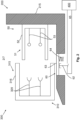
- a safety device 60 is provided at least partially in the area of charging component 50, e.g. in the immediate vicinity of it (e.g. arranged at most 1 mm or at most 5 mm or at most 1 cm or at most 4 cm from charging component 50).
- the safety device 60 is arranged directly on a battery housing 215 of the battery 210 .
- the safety device 60 preferably has at least one actuating element 63, in particular a rocker, which extends at least partially in the connection region V.
- the movement of the actuating element 63 can actuate a switching means 62, preferably an opener and/or button, which opens a safety path 65, for example.
- a switching means 62 preferably an opener and/or button
- a spring element 64 is also provided, which can be connected to the actuating element 63 .
- a spring-loaded actuating element 63 can thereby be provided in order to close the circuit in the normal state (with an open charging connection).
- FIG 3 the structure of the safety device 60 is shown in more detail.
- a charging plug 315 is shown in dashed lines to reflect the position of the charging plug 315 in the charging socket 51 .
- the design of the switching means 62 is shown as a button which is actuated by the (possibly spring-loaded) actuating element 63 .
- the arrangement of the components of the safety device 60 in the area of the charging socket 51 can also be seen, with the attachment of the shown parts of the safety device 60 to a battery housing 215 or to a housing 61 of the safety device 60 being recognizable.
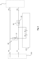
- FIG 4 the basic structure of a charging system 300 according to the invention and a battery system 200 according to the invention is shown schematically.
- a rechargeable battery 210 of the vehicle 1 is provided for operating, in particular for moving, a vehicle 1 .
- the battery 210 can have one or more battery cells 211, as is shown schematically.
- rechargeable battery 210 is connected to vehicle component 2 via a second and third connection point P2, P3.
- the Vehicle component 2 can optionally also include an electrical network and/or an on-board network of vehicle 1 (e.g. in addition to the electric motor).
- the energy supply of the vehicle component 2 is made possible in particular by a first current path 231 connecting the third connection point P3 to a positive pole 212 of the battery 210, and a second current path 232 connecting the second connection point P2 to a negative pole 213 of the battery.
- electronic switching elements 20 can be provided in the respective current paths 231, 232.
- the switching elements 20 make it possible to block the current flow in the switched-off switching state and to allow the current flow in the switched-on switching state.
- the electronic switching elements 20 are designed as semiconductor switches, so that the respective switching element 20 preferably blocks the flow of current in only one current direction in the switched-off switching state. This enables complex and flexible control of the current flow, in particular by a battery management system 400.
- the battery management system 400 can be electrically connected to the respective switching elements 20 and/or control them, for example via control paths S, in particular via a first and second control path S1, S2 .
- a further switching element 30 may be provided in at least one of the current paths, in particular in the first current path 231 . If necessary, this can also be controlled by the battery management system 400 via at least one corresponding further control path S3. It can be possible that a first electronic switching element 21 is connected directly to the positive pole 212 of the battery 210 and a second electronic switching element 22 is connected directly to the negative pole 213 of the battery 210 . It is also conceivable that a measurement M or a measurement path M is provided, which enables the battery 210 to be monitored by the battery management system 400 . In this case, electrical signals can preferably be output via the control paths S as a function of this measurement and/or monitoring, in order in this way to control the respective electronic switching elements 20 as a function of the monitoring and/or measurement.
- both the first electronic switching element 21 and the second electronic switching element 22 are switched on (and thus allow current to flow through the respective current paths 231, 232).
- the charging system 300 can have a charging device 310 for charging the battery 210 .
- the charging device 310 comprises, for example, at least one charging plug 315 and/or at least one electrical switching component 320 for detecting the electrical charging connection.
- connection points P1, P3 of the battery system 200 can be connected to corresponding connection points P1, P3 of the battery system 200.
- a connection point is used for a first of the connections of the charging device 310, with which the connection to the vehicle component 2 also takes place (for example the third connection point P3).
- a first connection point P1 is also provided as a charging connection point, which serves (in particular exclusively) for contacting a second connection of the connections of the charging device 310 .
- the first connection point P1 is integrated in the battery system 200 in such a way that an electrical connection between the battery 210 and the first connection point P1 is maintained even when the (second) switching state is switched off and/or independently of a (second) switching state of the second electronic Switching element 22 is possible.
- the safety when charging the battery 210 can be increased by the second electronic switching element 22 being switched to a switched-off switching state during the charging process (eg when a mechanical and/or electrical charging connection is detected). This causes a current flow to the vehicle component 2 to be blocked in such a way that a sufficient energy supply for operating the vehicle component 2 is prevented.
- At least one switching component 320 can be provided on the charging plug 315. So is in figure 6 shown schematically that, based on the at least one switching component 320, electrical contacting of the charging device 310 can be detected with the charging component 50 of the battery system 200 .
- the mechanical charging connection can be detected by the processing device 410 or another processing device 410, as in relation to FIG Figures 1 to 3 was explained, e.g. by monitoring a current flow through the safety path 65.
- a signal can then be output via at least one of the control paths S, for example, in order in particular to convert the second electronic switching element 22 into the switched-off switching state.
- the at least one switching component 320 is used to bridge two signal lines when contact is made (as in figure 6 you can see).
- the switching component 320 can be designed, for example, as an electrical (in particular electrically conductive) auxiliary contact, for example made of at least one metal.
- the switching component 320 is permanently connected to the charging plug 315 .
- the charging plug 315 can have a first connection A1 and a second connection A2.
- first connection A1 can be brought into contact with first connection point P1 and second connection A2 can be brought into contact with third connection point P3.
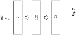
- a method 100 according to the invention is schematically visualized.
- a charging device 310 is connected to a charging component 50 of the battery system 200 in order to establish a mechanical and electrical charging connection.
- a second method step 102 switching off at least one electronic switching element 20 into a switched-off switching state is initiated when the mechanical charging connection is detected, so that the energy supply to the vehicle component 2 is predominantly reduced and/or completely interrupted.
- a third method step 103 a charging process for charging a battery 210 by the charging device 310 is initiated.
Landscapes
- Engineering & Computer Science (AREA)
- Power Engineering (AREA)
- Transportation (AREA)
- Mechanical Engineering (AREA)
- Life Sciences & Earth Sciences (AREA)
- Sustainable Development (AREA)
- Sustainable Energy (AREA)
- Computer Security & Cryptography (AREA)
- Charge And Discharge Circuits For Batteries Or The Like (AREA)
- Electric Propulsion And Braking For Vehicles (AREA)
Description
Die vorliegende Erfindung betrifft ein Batteriesystem für ein Fahrzeug. Ferner bezieht sich die Erfindung auf ein Ladesystem sowie ein Verfahren.The present invention relates to a battery system for a vehicle. Furthermore, the invention relates to a charging system and a method.
Aus
Aus
Aus dem Stand der Technik ist des Weiteren bekannt, dass Fahrzeuge, insbesondere Flurförderzeuge wie Gabelstapler, elektrisch betrieben und/oder angetrieben werden. Zur Energieversorgung einer Fahrzeugkomponente, bspw. eines Elektromotors, kommen dabei wiederaufladbare Batterien als Energiequelle zum Einsatz. Die wiederaufladbare Batterie (Akkumulator) des Fahrzeuges ist dabei bspw. als Lithiumbatterie (insbesondere Lithium-Ionen-Batterie) ausgeführt, um auch bei kurzzeitigen Zwischenladungen einen langen Betrieb des Fahrzeuges ermöglichen zu können. Bereits kurze Zwischenladungen können dabei oft den Betrieb (d. h. die Nutzungsdauer) des Fahrzeuges um Stunden verlängern.It is also known from the prior art that vehicles, in particular industrial trucks such as forklifts, are operated and/or driven electrically. To supply energy to a vehicle component, for example an electric motor, rechargeable batteries are used as an energy source. The rechargeable battery (accumulator) of the vehicle is designed, for example, as a lithium battery (in particular a lithium-ion battery) in order to be able to enable long-term operation of the vehicle even with short-term opportunity charging. Even short opportunity charges can often extend the operation (ie the service life) of the vehicle by hours.
Aus diesem Grunde werden in der Praxis Zwischenladungen der Batterie immer populärer, um bspw. das Fahrzeug kurzfristig in Betrieb nehmen zu können und die Nutzungsdauer zu verlängern. Daher ist es oft gewünscht, dass eine Kontaktierung des Fahrzeuges bzw. der Batterie an ein Ladegerät einfach und/oder schnell und/oder ergonomisch gestaltet wird. Herkömmlicherweise wird hierzu die Batterie über dieselben Verbindungspunkte sowohl mit dem Fahrzeug (bspw. dem Fahrzeugbordnetz) als auch mit dem Ladegerät verbunden.For this reason, opportunity charging of the battery is becoming more and more popular in practice, for example to be able to put the vehicle into operation at short notice and to extend the service life. It is therefore often desirable for the vehicle or the battery to be connected to a charging device in a simple and/or quick and/or ergonomic manner. For this purpose, the battery is conventionally connected to both the vehicle (e.g. the vehicle electrical system) and the charger via the same connection points.
Dabei kann es möglich sein, dass sowohl das Fahrzeug (d. h. ein Fahrzeugbordnetz bzw. die Fahrzeugkomponente) als auch ein Ladestecker des Ladegeräts elektrisch mit der Batterie kontaktiert. Entsprechend kann das Fahrzeug während des Ladevorgangs betriebsbereit sein, da die Energieversorgung durch die Batterie aufrecht erhalten bleibt. Hierbei muss allerdings vermieden werden, dass bei einer unachtsamen Handhabung, bspw. bei einem Losfahren mit dem Fahrzeug, das noch kontaktierte Ladegerät und/oder das Fahrzeug beschädigt wird.It may be possible that both the vehicle (i.e. a vehicle electrical system or the vehicle component) and a charging plug of the charger make electrical contact with the battery. Accordingly, the vehicle can be operational during the charging process, since the energy supply from the battery is maintained. However, careless handling, for example when driving off with the vehicle, must prevent damage to the charger that is still in contact and/or the vehicle.
Um dies zu verhindern, müssen technisch aufwendige und komplexe Maßnahmen getroffen werden. So kann bspw. vorgesehen sein, dass zunächst manuell die Verbindung der Batterie zur Fahrzeugkomponente (bzw. Fahrzeugbordnetz) getrennt wird und erst im Anschluss daran das Ladegerät zum Aufladen kontaktiert wird. Dies ist allerdings wenig ergonomisch und zeitaufwendig. Die Dauer für eine Zwischenladung wird damit drastisch erhöht.In order to prevent this, technically complicated and complex measures must be taken. For example, it can be provided that the connection of the battery to the vehicle component (or vehicle electrical system) is first disconnected manually and only then is the charger contacted for charging. However, this is not very ergonomic and time-consuming. The duration for an opportunity charge is thus drastically increased.
Es ist daher eine Aufgabe der vorliegenden Erfindung, die voranstehend beschriebenen Nachteile zumindest teilweise zu beheben. Insbesondere ist es eine Aufgabe der vorliegenden Erfindung, eine sicherere und/oder schnellere und/oder ergonomischere Möglichkeit zur Aufladung der Batterie bereitzustellen.It is therefore an object of the present invention to at least partially eliminate the disadvantages described above. In particular, it is an object of the present invention to provide a safer and/or faster and/or more ergonomic way of charging the battery.
Die voranstehende Aufgabe wird gelöst durch ein Batteriesystem mit den Merkmalen des unabhängigen Systemanspruchs 1, ein Ladesystem mit den Merkmalen des weiteren nebengeordneten Systemanspruchs sowie durch ein Verfahren mit den Merkmalen des unabhängigen Verfahrensanspruchs. Weitere Merkmale und Details der Erfindung ergeben sich aus den jeweiligen Unteransprüchen, der Beschreibung und den Zeichnungen. Dabei gelten Merkmale und Details, die im Zusammenhang mit dem erfindungsgemäßen Batteriesystem beschrieben sind, selbstverständlich auch im Zusammenhang mit dem erfindungsgemäßen Ladesystem sowie dem erfindungsgemäßen Verfahren, und jeweils umgekehrt, so dass bzgl. der Offenbarung zu den einzelnen Erfindungsaspekten stets wechselseitig Bezug genommen wird bzw. werden kann.The above object is achieved by a battery system having the features of the independent system claim 1, a charging system having the features of the further subordinate system claim and by a method having the features of the independent method claim. Further features and details of the invention result from the respective dependent claims, the description and the drawings. Features and details apply in connection with the invention Battery system are described, of course also in connection with the charging system according to the invention and the method according to the invention, and in each case vice versa, so that the disclosure of the individual aspects of the invention is always mutually referred to or can be referred to.
Die Aufgabe wird insbesondere gelöst durch ein Batteriesystem für ein Fahrzeug gemäß dem unabhängigen Vorrichtungsanspruch 1, vorzugsweise für ein Flurförderzeug, neben den weiteren Merkmalen des Anspruchs 1 aufweisend:
- wenigstens eine wiederaufladbare Batterie, insbesondere Lithium-Ionen Batterie, zur (elektrischen) Energieversorgung wenigstens einer Fahrzeugkomponente des Fahrzeuges,
- eine Ladekomponente zur mechanischen und elektrischen Ladeverbindung mit einer externen Ladevorrichtung, um in einem Ladezustand (des Batteriesystems) die Batterie durch die Ladevorrichtung aufzuladen, vorzugsweise durch eine Herstellung einer elektrischen Verbindung und/oder elektrischen Energieübertragung zwischen der Ladevorrichtung und der Batterie,
- eine Sicherheitsvorrichtung, welche zumindest teilweise (räumlich) im Bereich der Ladekomponente angeordnet ist, um die mechanische Ladeverbindung der Ladekomponente mit der Ladevorrichtung zu detektieren, vorzugsweise sodass eine Sicherheitsunterbrechung der Energieversorgung der Fahrzeugkomponente im Ladezustand durchführbar ist, bevorzugt dadurch dass eine elektrische Verbindung zwischen der Fahrzeugkomponente und der Batterie zumindest teilweise unterbrochen wird und/oder ein Stromfluss zwischen der Batterie und der Fahrzeugkomponente zumindest teilweise unterbunden wird und/oder ein Hauptstrom zum Fahrzeug zumindest teilweise unterbrochen wird.
- at least one rechargeable battery, in particular a lithium-ion battery, for supplying (electrical) energy to at least one vehicle component of the vehicle,
- a charging component for the mechanical and electrical charging connection with an external charging device in order to charge the battery by the charging device in a charging state (of the battery system), preferably by establishing an electrical connection and/or electrical energy transmission between the charging device and the battery,
- a safety device which is at least partially (spatially) arranged in the area of the charging component in order to detect the mechanical charging connection of the charging component to the charging device, preferably so that a safety interruption of the energy supply to the vehicle component can be carried out in the charging state, preferably by an electrical connection between the vehicle component and the battery is at least partially interrupted and/or a current flow between the battery and the vehicle component is at least partially prevented and/or a main current to the vehicle is at least partially interrupted.
Dies hat den Vorteil, dass bereits bei Detektion der mechanischen Ladeverbindung zwischen der Ladekomponente und der Ladevorrichtung die Energieversorgung der Fahrzeugkomponente verhindert wird, insbesondere ein Hauptstrom des Fahrzeuges unterbrochen wird. Eine solche mechanische Ladeverbindung ist bspw. ein Formschluss eines Ladesteckers der Ladevorrichtung mit einer Ladebuchse der Ladekomponente.This has the advantage that as soon as the mechanical charging connection between the charging component and the charging device is detected, the power supply to the vehicle component is prevented, in particular a main current of the vehicle is interrupted. Such a mechanical charging connection is, for example, a positive connection of a charging plug of the charging device with a charging socket of the charging component.
Es kann somit auch ein Problem zumindest reduziert werden, welches auftritt, wenn lediglich die elektrische Ladeverbindung detektiert wird. Um eine elektrische Ladeverbindung zu detektieren, kann bspw. eine elektrisch leitende Brücke (bzw. eine Umschaltkomponente) im Ladestecker (Ladegerätestecker) vorgesehen sein, welche beim Einstecken mit Leitern des Batteriesystems kontaktiert und somit einen Stromkreis schließt. Dies kann dann als elektrische Ladeverbindung detektiert werden. Hierdurch kann ferner die Unterbrechung der Energieversorgung ausgelöst werden. Allerdings kann es problematisch sein, wenn ein Defekt der Brücke vorliegt und/oder die mechanische Ladeverbindung (wie eine mechanische Verriegelung des Steckergehäuses mit dem Buchengehäuse) vor der elektrischen Ladeverbindung hergestellt wird. In diesem Fall ist die Ladevorrichtung bzw. der Ladestecker mit der Ladekomponente verbunden, was allerdings nicht zuverlässig detektiert werden kann. Ein weiteres Problem ist, dass stets eine solche Umschaltkomponente im Ladestecker vorgesehen sein muss, was zu zusätzlichen Kosten und Aufwand führt, sowie ggf. Bauraum reduziert. Bei dem erfindungsgemäßen Batteriesystem kann hingegen vorgesehen sein, dass die mechanische Ladeverbindung erkannt wird, um die Sicherheitsunterbrechung durchzuführen. Entsprechend kann die erfindungsgemäße Lösung Kosten und technischen Aufwand reduzieren sowie die Sicherheit erhöhen.A problem can thus also be at least reduced, which occurs when only the electrical charging connection is detected. In order to have an electrical charging connection For example, an electrically conductive bridge (or a switching component) can be provided in the charging plug (charger plug), which makes contact with the conductors of the battery system when it is plugged in and thus closes a circuit. This can then be detected as an electrical charging connection. This can also trigger the interruption of the power supply. However, it can be problematic if there is a defect in the bridge and/or the mechanical charging connection (such as a mechanical locking of the plug housing with the socket housing) is made before the electrical charging connection. In this case, the charging device or the charging plug is connected to the charging component, which, however, cannot be reliably detected. A further problem is that such a switching component must always be provided in the charging plug, which leads to additional costs and effort and possibly reduces installation space. In the battery system according to the invention, on the other hand, it can be provided that the mechanical charging connection is recognized in order to carry out the safety interruption. Accordingly, the solution according to the invention can reduce costs and technical complexity and increase security.
Vorzugsweise wird dabei unter einer mechanischen Ladeverbindung eine physikalische und/oder nicht-elektrische Kontaktierung der Ladevorrichtung, insbesondere eines Gehäuses eines Ladesteckers der Ladevorrichtung, mit der Ladekomponente, insbesondere mit einem Gehäuse einer Ladebuchse der Ladekomponente, verstanden. Bevorzugt ist dabei die Ladeverbindung eine kraft- und/oder formschlüssige und/oder lösbare Verbindung zwischen der Ladevorrichtung und der Ladekomponente. Bspw. können hierzu wenigstens ein elastisches und/oder federndes (Gehäuse-) element und/oder wenigstens ein Rastmittel wenigstens eines der Gehäuse zum Einsatz kommen, um einen solchen Form- und/oder Kraftschluss herzustellen. Wenigstens eines der Gehäuse und/oder der Elemente und/oder der Rastmittel können dabei ggf. aus einem Kunststoff hergestellt sein. Dies ermöglicht eine einfache und sichere Kontaktierung der Ladevorrichtung zum Aufladen der Batterie.A mechanical charging connection is preferably understood to mean physical and/or non-electrical contacting of the charging device, in particular a housing of a charging plug of the charging device, with the charging component, in particular with a housing of a charging socket of the charging component. The charging connection is preferably a non-positive and/or positive and/or detachable connection between the charging device and the charging component. For example, at least one elastic and/or resilient (housing) element and/or at least one latching means of at least one of the housings can be used for this purpose in order to produce such a positive and/or non-positive connection. At least one of the housings and/or the elements and/or the latching means can optionally be made from a plastic. This enables easy and safe contacting of the charging device for charging the battery.
Von weiterem Vorteil kann vorgesehen sein, dass die Ladekomponente komplementär zur Ladevorrichtung ausgebildet ist, um die mechanische Ladeverbindung als eine lösbare kraft-und/oder formschlüssige Verbindung herzustellen. Bspw. kann hierzu die Ladekomponente eine Ladebuchse aufweisen, welche komplementär zu einem Ladestecker (Stecker) der Ladevorrichtung (bspw. eines Ladegeräts) ausgebildet ist. In anderen Worten kann die Ladebuchse hinsichtlich der Geometrie und/oder des Durchmessers einer Öffnung der Ladebuchse und/oder der Länge dazu ausgeführt sein, einen Ladestecker aufzunehmen. Durch diese Aufnahme kann dann die mechanische Ladeverbindung hergestellt werden. Zur form- und/oder kraftschlüssigen Verbindung ist bspw. wenigstens ein Rastmittel bei der Ladekomponente und/oder der Ladevorrichtung vorgesehen, welche(s) bei der Aufnahme (also z. B. dem Einführen des Steckers) einen Formschluss und/oder Kraftschluss herstellt. Somit wird eine sichere und zuverlässige mechanische Verbindung gewährleistet. Gleichzeitig kann durch die Kontaktierung von elektrischen Anschlüssen der Ladekomponente und der Ladevorrichtung miteinander die elektrische Ladeverbindung hergestellt werden.A further advantage can be that the charging component is designed to complement the charging device in order to produce the mechanical charging connection as a detachable non-positive and/or positive connection. For example, the charging component can have a charging socket for this purpose, which is designed to complement a charging plug (plug) of the charging device (for example a charging device). In other words, it can Charging socket be designed in terms of geometry and / or the diameter of an opening of the charging socket and / or the length to accommodate a charging connector. The mechanical charging connection can then be established through this recording. For the positive and/or non-positive connection, at least one locking means is provided on the charging component and/or the charging device, for example, which creates a positive and/or non-positive connection when receiving it (e.g. inserting the plug). This ensures a safe and reliable mechanical connection. At the same time, the electrical charging connection can be established by the electrical connections of the charging component and the charging device being in contact with one another.
Vorzugsweise kann die Sicherheitsvorrichtung ein Betätigungselement aufweisen, welches derart angrenzend zur Ladekomponente, insbesondere einer Ladebuchse, angeordnet ist, dass vor und/oder bei der Herstellung der (insbesondere mechanischen) Ladeverbindung eine Kraftausübung durch die Ladevorrichtung, insbesondere einem Ladestecker, vorzugsweise eines Gehäuseteils des Ladesteckers auf das Betätigungselement erfolgt, sodass durch das Betätigungselement die Detektion durchführbar ist. Bspw. kann das Betätigungselement hierbei beweglich ausgeführt sein und/oder beweglich und/oder schwenkbar an einem Gehäuse der Sicherheitsvorrichtung und/oder der Ladekomponente gelagert sein. Vorzugsweise ist das Betätigungselement als Wippe ausgebildet. Dies hat den Vorteil, dass eine einfache und zuverlässige Detektion der mechanischen Ladeverbindung erfolgen kann. Insbesondere erfolgt dabei die Betätigung des Betätigungselements ausschließlich mechanisch (und damit nicht elektrisch wie bei der Umschaltkomponente).The safety device can preferably have an actuating element, which is arranged adjacent to the charging component, in particular a charging socket, in such a way that before and/or during the establishment of the (in particular mechanical) charging connection, a force is exerted by the charging device, in particular a charging plug, preferably a housing part of the charging plug takes place on the actuating element, so that the detection can be carried out by the actuating element. For example, the actuating element can be designed to be movable and/or be mounted movably and/or pivotably on a housing of the safety device and/or the charging component. The actuating element is preferably designed as a rocker. This has the advantage that the mechanical charging connection can be detected easily and reliably. In particular, the actuating element is actuated exclusively mechanically (and thus not electrically as in the switchover component).
Vorzugsweise ist das Ladekomponentengehäuse, insbesondere ein Gehäuseteil, welches eine Ladebuchse trägt, derart geformt, dass ein Sicherheitspfad der Sicherheitsvorrichtung geöffnet wird, bevor oder wenn ein Formschluss zwischen dem Ladestecker und der Ladebuche hergestellt ist. Bevorzugt ist hierzu ein Betätigungselement am Gehäuseteil vorgesehen, um die Bewegung in den Formschluss zu erfassen. Bspw. erfolgt hierzu eine Anordnung des Betätigungselements derart am Gehäuseteil, dass dieses in einen Verbindungsbereich (z. B. vor Rastmitteln oder dergleichen zum Formschluss) angeordnet ist, um die Bewegung in den Formschluss zu erfassen. Damit kann der gefahrbringende Formschluss bereits erkannt werden, wenn sich der Ladestecker der endgültigen Position in der Ladebuchse nähert. Es wird dabei der (eingeleitete) Formschluss erkannt und nicht der elektrische Kontakt (also die elektrische Ladeverbindung), was die Sicherheit deutlich erhöhen kann. Auch ein fehlerhafter elektrischer Kontakt führt damit nicht zu einem Sicherheitsrisiko.The charging component housing, in particular a housing part which carries a charging socket, is preferably shaped in such a way that a safety path of the safety device is opened before or when a positive connection is established between the charging plug and the charging socket. For this purpose, an actuating element is preferably provided on the housing part in order to detect the movement into the form fit. For example, the actuating element is arranged on the housing part in such a way that it is arranged in a connection area (e.g. in front of latching means or the like for the form fit) in order to detect the movement into the form fit. This means that the dangerous form closure can already be detected when the charging connector is in its final position approaching the charging socket. The (initiated) form fit is recognized and not the electrical contact (i.e. the electrical charging connection), which can significantly increase safety. Even a faulty electrical contact does not lead to a safety risk.
Optional kann es möglich sein, dass ausschließlich die mechanische Ladeverbindung, und damit nicht die elektrische Ladeverbindung, detektiert wird. Dies hat den Vorteil, dass der technische Aufwand sowie die Kosten für die Detektion, insbesondere für eine elektrische Umschaltkomponente, reduziert werden können.Optionally, it can be possible that only the mechanical charging connection, and thus not the electrical charging connection, is detected. This has the advantage that the technical outlay and the costs for the detection, in particular for an electrical switching component, can be reduced.
Vorzugsweise ist die Ladekomponente an einem Batteriegehäuse angeordnet, bevorzugt fest und/oder unbeweglich am Batteriegehäuse befestigt, und insbesondere die Sicherheitsvorrichtung zumindest teilweise zwischen der Ladekomponente und dem Batteriegehäuse angeordnet, vorzugsweise befestigt. Hierdurch kann insbesondere der notwendige Bauraum reduziert werden.The charging component is preferably arranged on a battery housing, preferably attached firmly and/or immovably to the battery housing, and in particular the safety device is arranged at least partially between the charging component and the battery housing, preferably attached. In this way, in particular, the necessary installation space can be reduced.
Optional kann bei dem erfindungsgemäßen Batteriesystem vorgesehen sein, dass die Ladevorrichtung extern und/oder separat und/oder räumlich beabstandet von der Ladekomponente ausgeführt und/oder angeordnet ist, und bevorzugt nicht Teil des erfindungsgemäßen Batteriesystems ist. Damit wird der Vorteil erzielt, dass auch unterschiedliche Ladevorrichtungen als Ladegerät zum Einsatz kommen können.In the battery system according to the invention, it can optionally be provided that the charging device is designed and/or arranged externally and/or separately and/or spatially at a distance from the charging component, and is preferably not part of the battery system according to the invention. This achieves the advantage that different charging devices can also be used as charging devices.
Erfindungsgemäß ist es vorgesehen, dass ein (insbesondere rein) mechanisches Betätigungselement der Sicherheitsvorrichtung unmittelbar oder benachbart an einem Gehäuse der Ladekomponente angeordnet ist, nämlich in einem Verbindungsbereich, in welchem die Ladevorrichtung, insbesondere ein Ladestecker, zur Ladeverbindung mit der Ladekomponente, insbesondere einer Ladebuchse, durch eine Kontaktierungsbewegung einbringbar ist, sodass das Betätigungselement durch die Kontaktierungsbewegung der Ladevorrichtung betätigbar, insbesondere bewegbar, ausgeführt ist. Entsprechend kann es möglich sein, dass bei dem Einbringen der Ladevorrichtung bzw. des Ladesteckers in die Ladekomponente bzw. die Ladebuchse eine Kraftausübung auf das Betätigungselement durch die Ladevorrichtung bzw. den Ladestecker erfolgt, da bspw. das Betätigungselement in dem Verbindungsbereich angeordnet ist, in welchem bei vollständiger mechanischer Ladeverbindung sich die Ladevorrichtung bzw. der Ladestecker erstreckt. Dies hat den Vorteil, dass eine einfache und kostengünstige Detektion möglich ist, welche aufgrund der Erfassung der räumlichen Präsenz der Ladevorrichtung im Verbindungsbereich besonders zuverlässig die mechanische Ladeverbindung erkennt.According to the invention, it is provided that an (in particular purely) mechanical actuating element of the safety device is arranged directly or adjacent to a housing of the charging component, namely in a connection area in which the charging device, in particular a charging plug, for the charging connection with the charging component, in particular a charging socket, can be introduced by a contacting movement, so that the actuating element can be actuated, in particular moved, by the contacting movement of the charging device. Accordingly, it may be possible that when the charging device or the charging plug is inserted into the charging component or the charging socket, a force is exerted on the actuating element by the charging device or the charging plug, since, for example, the actuating element is arranged in the connection area in which at full mechanical Charging connection extends the charging device or the charging plug. This has the advantage that simple and cost-effective detection is possible, which detects the mechanical charging connection particularly reliably due to the detection of the spatial presence of the charging device in the connection area.
Es ist im Rahmen der Erfindung vorgesehen, dass ein mechanisches Betätigungselement der Sicherheitsvorrichtung derart in dem Verbindungsbereich der Ladekomponente angeordnet ist, dass eine Kraftausübung durch die Ladevorrichtung im Zuge einer Herstellung der mechanischen Ladeverbindung zeitlich vor einer Kontaktierung wenigstens eines elektrischen Kontakts der Ladevorrichtung mit einem jeweiligen Gegenkontakt der Ladekomponente erfolgt. Die Kontaktierung, d. h. die elektrische Verbindung des elektrischen Kontakts mit dem Gegenkontakt, dient dabei bspw. zur Energieübertragung von der Ladevorrichtung zur Batterie. Bspw. ist hier die Ladevorrichtung als ein Ladegerät ausgeführt, welches ein Ladeverfahren zur Aufladung der Batterie durchführt. Somit ist eine zuverlässige Aufladung möglich.It is provided within the scope of the invention that a mechanical actuating element of the safety device is arranged in the connection area of the charging component in such a way that force is exerted by the charging device in the course of establishing the mechanical charging connection before at least one electrical contact of the charging device makes contact with a respective mating contact the charging component takes place. The contact, i. H. the electrical connection of the electrical contact to the counter-contact serves, for example, to transfer energy from the charging device to the battery. For example, the charging device is designed here as a charging device that carries out a charging method for charging the battery. Reliable charging is thus possible.
Von weiterem Vorteil kann vorgesehen sein, dass ein elektrisches Schaltmittel der Sicherheitsvorrichtung vorgesehen ist, und insbesondere in einen elektrischen Sicherheitspfad des Batteriesystems integriert ist, vorzugsweise über den Sicherheitspfad mit einem Batteriemanagementsystem verbindbar ist, um zur Detektion der mechanischen Ladeverbindung den Sicherheitspfad zu unterbrechen. Bspw. ist das Batteriemanagementsystem mit dem Sicherheitspfad elektrisch über wenigstens zwei elektrische Leitungen verbunden, welche somit mit dem Schaltmittel einen Stromkreis bilden. Bei einer Unterbrechung durch das Schaltmittel kann daher ein Stromfluss durch den Stromkreis unterbunden werden. insbesondere kann diese Unterbrechung durch das Batteriemanagementsystem zur Detektion der mechanischen Ladeverbindung ermittelt werden, bspw. durch eine Auswerte- und/oder Verarbeitungsvorrichtung (insbesondere als eine Überwachungs- und/oder Betriebsvorrichtung) des Batteriemanagementsystems. Besonders bevorzugt ist dabei das Schaltmittel als Taster ausgeführt, welcher durch das Betätigungselement betätigt wird. Somit kann zuverlässig die Detektion erfolgen. insbesondere bietet es dabei einen Vorteil, wenn das Schaltmittel den Sicherheitspfad zur Detektion unterbricht, und somit vorzugsweise als Öffner ausgeführt ist. Damit kann gewährleistet werden, dass auch im Fehlerfall (bei unterbrochenem Strom) die Energieversorgung der Fahrzeugkomponente unterbunden wird.Another advantage can be that an electrical switching means of the safety device is provided and is integrated in particular in an electrical safety path of the battery system, preferably can be connected to a battery management system via the safety path in order to interrupt the safety path to detect the mechanical charging connection. For example, the battery management system is electrically connected to the safety path via at least two electrical lines, which thus form a circuit with the switching means. In the event of an interruption by the switching means, a current flow through the circuit can therefore be prevented. In particular, this interruption can be determined by the battery management system for detecting the mechanical charging connection, for example by an evaluation and/or processing device (in particular as a monitoring and/or operating device) of the battery management system. The switching means is particularly preferably designed as a button which is actuated by the actuating element. The detection can thus be carried out reliably. In particular, it offers an advantage if the switching means interrupts the safety path for detection, and is therefore preferably designed as an opener. With that can ensure that the power supply to the vehicle components is cut off even in the event of a fault (if the power is interrupted).
Des Weiteren kann vorgesehen sein, dass
- - in einem Normalzustand (des Batteriesystems) das Schaltmittel den Sicherheitspfad schließt, sodass ein Stromfluss durch den Sicherheitspfad erfolgt, um eine mechanisch mit der Ladevorrichtung unverbundene Ladekomponente zu detektieren, und
- - im Ladezustand (des Batteriesystems) das Schaltmittel den Sicherheitspfad öffnet, sodass der Stromfluss vollständig oder im Wesentlichen verhindert ist, um eine mechanisch mit der Ladevorrichtung verbundene Ladekomponente zu detektieren.
- - In a normal state (of the battery system), the switching means closes the safety path, so that a current flows through the safety path in order to detect a charging component that is mechanically unconnected to the charging device, and
- - In the state of charge (of the battery system), the switching means opens the safety path, so that the flow of current is completely or essentially prevented in order to detect a charging component mechanically connected to the charging device.
Bspw. kann hierbei im Normalzustand die Energieversorgung zur Fahrzeugkomponente hergestellt sein, und im Ladezustand unterbunden sein. Bspw. erfolgt eine Auswertung des Stromflusses durch eine Verarbeitungsvorrichtung (insbesondere als eine Überwachungs-und/oder Betriebsvorrichtung) des Batteriemanagementsystems. Insbesondere hat dies den Vorteil, dass bei einem fehlerhaft unterbrochenen Stromfluss das Batteriesystem in einen sicheren Zustand überführt wird.For example, the power supply to the vehicle component can be established in the normal state and prevented in the charging state. For example, the current flow is evaluated by a processing device (in particular as a monitoring and/or operating device) of the battery management system. In particular, this has the advantage that the battery system is transferred to a safe state if the current flow is interrupted incorrectly.
Nach einer weiteren Möglichkeit kann vorgesehen sein, dass ein Betätigungselement, insbesondere eine mechanische Wippe, benachbart zu einem Schaltmittel angeordnet ist, und vorzugsweise beweglich an einem Gehäuse der Sicherheitsvorrichtung und/oder an einem Gehäuse der Ladekomponente gelagert ist, um insbesondere bei einer Kraftausübung auf das Betätigungselement das Schaltmittel durch eine zumindest teilweise lineare oder Dreh- oder Kipp- oder Schwenkbewegung des Betätigungselements zu betätigen. Damit kann die mechanische Bewegung aufgrund der Herstellung der mechanischen Ladeverbindung genutzt werden, um ein elektrisches Signal zu erzeugen (hier insbesondere: Unterbrechung des Stromflusses). Insbesondere kann ein Batteriemanagementsystem dieses Signal erfassen, um die mechanische Ladeverbindung zu detektieren, und bei positiver Detektion die Energieversorgung der Fahrzeugkomponente zu unterbrechen. Bspw. ist dabei das Schaltmittel als elektronischer oder mechanischer Schalter, insbesondere Taster, bspw. als Transistor, ausgeführt, um den Stromfluss zu unterbinden. Insbesondere ist das Betätigungselement federbelastet ausgeführt, z. B. durch ein Federelement, um im Normalzustand bei unverbundener Ladeverbindung das Schaltmittel nicht zu betätigen bzw. zu schließen.According to a further possibility, it can be provided that an actuating element, in particular a mechanical rocker, is arranged adjacent to a switching means and is preferably movably mounted on a housing of the safety device and/or on a housing of the charging component, in order to, in particular, when a force is exerted on the Actuating element to actuate the switching means by an at least partially linear or rotary or tilting or pivoting movement of the actuating element. This means that the mechanical movement due to the establishment of the mechanical charging connection can be used to generate an electrical signal (here in particular: interruption of the current flow). In particular, a battery management system can detect this signal in order to detect the mechanical charging connection and to interrupt the power supply to the vehicle component if the detection is positive. For example, the switching means is in the form of an electronic or mechanical switch, in particular a button, for example a transistor, in order to prevent the flow of current. In particular, the actuating element is spring-loaded, e.g. B. by a spring element to im Normal state with an unconnected charging connection not to actuate or close the switching means.
Weiter ist im Rahmen der Erfindung denkbar, dass wenigstens ein elektronisches Schaltelement zur Herstellung einer elektrischen Verbindung der Batterie mit der Fahrzeugkomponente vorgesehen ist, und ein Steuerungspfad, insbesondere eines Batteriemanagementsystems, elektrisch mit dem elektronischen Schaltelement verbunden ist, sodass bei der Detektion der mechanischen Ladeverbindung das elektronische Schaltelement über den Steuerungspfad in einen ausgeschalteten Schaltzustand bringbar ist, um die elektrische Verbindung der Batterie mit der Fahrzeugkomponente zumindest teilweise zu unterbrechen. Hierdurch kann zuverlässig die Energieversorgung der Fahrzeugkomponente bei Detektion der mechanischen Ladeverbindung unterbrochen werden, also die Sicherheitsunterbrechung initiiert werden. Bspw. ist hierbei das Schaltelement wie das Schaltmittel als elektronischer Schalter ausgeführt. Insbesondere ist dabei eine Verarbeitungsvorrichtung (vorzugsweise als eine Überwachungs- und/oder Betriebsvorrichtung) vorgesehen, um die Ansteuerung des Schaltelements über den Steuerungspfad durchzuführen.It is also conceivable within the scope of the invention that at least one electronic switching element is provided for establishing an electrical connection between the battery and the vehicle component, and a control path, in particular of a battery management system, is electrically connected to the electronic switching element, so that when the mechanical charging connection is detected, electronic switching element can be brought into a switched-off switching state via the control path in order to at least partially interrupt the electrical connection of the battery to the vehicle component. As a result, the energy supply to the vehicle component can be reliably interrupted when the mechanical charging connection is detected, ie the safety interruption can be initiated. For example, the switching element, like the switching means, is designed as an electronic switch. In particular, a processing device (preferably as a monitoring and/or operating device) is provided in order to trigger the switching element via the control path.
Des Weiteren kann vorgesehen sein, dass ein Batteriemanagementsystem vorgesehen ist, welches vorzugsweise elektrisch mit wenigstens einem Schaltelement über wenigstens einen oder jeweilige Steuerungspfade verbunden ist, sodass in Abhängigkeit von der Detektion der mechanischen Ladeverbindung:
- für einen Aufladevorgang (im Ladezustand) bei positiver Detektion ein erstes elektronisches Schaltelement in einen eingeschalteten ersten Schaltzustand und ein zweites elektronisches Schaltelement in einen ausgeschalteten zweiten Schaltzustand bringbar ist, und/oder
- für eine bereitgestellte Energieversorgung zur Fahrzeugkomponente bei negativer Detektion (im Normalzustand) das erste elektronische Schaltelement in einen eingeschalteten ersten Schaltzustand und das zweite elektronische Schaltelement in einen eingeschalteten zweiten Schaltzustand bringbar ist.
- for a charging process (in the charging state) in the event of positive detection, a first electronic switching element can be brought into a switched-on first switching state and a second electronic switching element can be brought into a switched-off second switching state, and/or
- for a provided energy supply to the vehicle component in the event of negative detection (in the normal state), the first electronic switching element can be brought into a switched-on first switching state and the second electronic switching element can be brought into a switched-on second switching state.
Ferner ist es denkbar, dass die Fahrzeugkomponente als elektrische Antriebskomponente, insbesondere als Elektromotor, des Fahrzeuges ausgeführt ist.Furthermore, it is conceivable that the vehicle component is designed as an electric drive component, in particular as an electric motor, of the vehicle.
Es kann möglich sein, dass beim erfindungsgemäßen Batteriesystem vorgesehen ist:
- wenigstens zwei (elektrische und/oder elektronische) Schaltelemente jeweils zur Herstellung und/oder Unterbrechung einer elektrischen Verbindung der Batterie mit der Fahrzeugkomponente, insbesondere zur Herstellung und/oder Unterbrechung der Energieversorgung der Fahrzeugkomponente.
- at least two (electrical and/or electronic) switching elements each for establishing and/or interrupting an electrical connection between the battery and the vehicle component, in particular for establishing and/or interrupting the power supply to the vehicle component.
Des Weiteren ist denkbar, dass ein Ladeverbindungspunkt vorgesehen ist, welcher elektrisch unabhängig von den (elektronischen) Schaltelementen elektrisch (ggf. fest und/oder unlösbar) mit der Batterie verbunden ist, und insbesondere zur (ggf. lösbaren) elektrischen Verbindung mit einer (externen) Ladevorrichtung ausgeführt ist, sodass vorzugsweise eine Aufladung der Batterie durch die Ladevorrichtung unabhängig von einem Schaltzustand und/oder bei einem ausgeschalteten Schaltzustand wenigstens (oder genau) eines der (elektronischen) Schaltelemente durchführbar ist. Damit wird der Vorteil erzielt, dass auch bei einer Aufladung die Energieversorgung zu der Fahrzeugkomponente unterbrochen werden kann, und damit die Sicherheitsunterbrechung der Energieversorgung der Fahrzeugkomponente bereitgestellt werden kann.It is also conceivable that a charging connection point is provided, which is electrically (possibly fixed and/or non-detachable) connected to the battery independently of the (electronic) switching elements, and in particular for (possibly detachable) electrical connection to an (external ) Charging device is designed so that preferably a charging of the battery by the charging device independently of a switching state and / or in a switched-off switching state at least (or exactly) one of the (electronic) switching elements can be performed. This achieves the advantage that the energy supply to the vehicle component can also be interrupted during charging, and the safety interruption of the energy supply to the vehicle component can thus be provided.
Bevorzugt ist dabei die Ladevorrichtung als eine externe Ladevorrichtung ausgeführt, d. h. außerhalb des Batteriesystems und/oder des Fahrzeuges vorgesehen.The charging device is preferably designed as an external charging device, i. H. provided outside of the battery system and/or the vehicle.
Insbesondere bezieht sich ein ausgeschalteter Schaltzustand auf einen gesperrten bzw. geöffneten Schaltzustand zum Sperren eines Stromflusses zumindest in eine Stromrichtung durch das entsprechende Schaltelement, wohingegen insbesondere ein eingeschalteter Schaltzustand sich auf einen freigegebenen bzw. geschlossenen Schaltzustand bezieht zur Freigabe des Stromflusses bezieht.In particular, a switched-off switching state refers to a blocked or opened switching state for blocking a current flow at least in one current direction through the corresponding switching element, whereas a switched-on switching state relates in particular to a released or closed switching state for enabling the current flow.
Vorzugsweise dient der ausgeschaltete Schaltzustand der Schaltelemente dazu, die jeweilige elektrische Verbindung zu unterbrechen, insbesondere einen elektrischen Stromfluss durch die jeweilige Verbindung zumindest überwiegend zu reduzieren, sodass die vollständige Energieversorgung der Fahrzeugkomponente unterbrochen werden kann. Die Energieversorgung wird dabei insbesondere dadurch unterbrochen, dass eine Energieübertragung über die Verbindung gesperrt wird.The switched-off switching state of the switching elements preferably serves to interrupt the respective electrical connection, in particular to at least predominantly reduce an electrical current flow through the respective connection, so that the complete power supply to the vehicle component can be interrupted. In this case, the energy supply is interrupted in particular by the fact that energy transmission via the connection is blocked.
Insbesondere ergibt sich ein Vorteil dadurch, dass der Ladeverbindungspunkt elektrisch unabhängig von den (elektronischen) Schaltelementen elektrisch mit der Batterie verbunden ist. Dies ermöglicht es, dass wenigstens einer der elektronischen Schaltelemente für das Aufladen in einen ausgeschalteten (d. h. geöffneten und/oder gesperrten) Schaltzustand überführt werden kann (d. h. in einen Sperrzustand gebracht wird), sodass insbesondere eine elektrische Verbindung der Fahrzeugkomponente mit der Batterie durch das Schaltelement gesperrt wird. In anderen Worten wird damit die Sicherheitsunterbrechung der Energieversorgung der Fahrzeugkomponente durchgeführt. Damit wird verhindert, dass eine Energieübertragung von der Batterie zur Fahrzeugkomponente vollständig erfolgt, und das Fahrzeug kann somit nicht fortbewegt bzw. betrieben werden. Mit anderen Worten kann trotz des angesteckten Ladegeräts (d. h. bspw. der Ladevorrichtung bzw. des Ladesteckers) und/oder trotz des Ladevorgangs die Energiezufuhr bzw. Energieversorgung zur Fahrzeugkomponente (d. h. zum Fahrzeug) unterbunden werden. Auf diese Weise kann ein effizienter Wegfahrschutz bereitgestellt werden. Dieser kann zudem technisch einfach und kostengünstig realisiert werden, da insbesondere keine weiteren Anpassungen am Fahrzeug notwendig sind. Insbesondere kann der Wegfahrschutz ausschließlich durch das Batteriesystem bereitgestellt sein.In particular, there is an advantage in that the charging connection point is electrically connected to the battery independently of the (electronic) switching elements. This makes it possible for at least one of the electronic switching elements for charging to be switched to a switched-off (i.e. open and/or blocked) switching state (i.e. brought into a blocked state), so that in particular an electrical connection between the vehicle component and the battery can be established by the switching element is blocked. In other words, the safety interruption of the energy supply to the vehicle component is thus carried out. This prevents energy from being completely transferred from the battery to the vehicle component, and the vehicle cannot therefore be moved or operated. In other words, the power supply or energy supply to the vehicle component (ie to the vehicle) can be prevented despite the plugged-in charger (i.e. e.g. the charging device or the charging plug) and/or despite the charging process. Efficient anti-theft protection can be provided in this way. In addition, this can be implemented in a technically simple and cost-effective manner, since in particular no further adjustments to the vehicle are necessary. In particular, the immobilizer can be provided exclusively by the battery system.
Gemäß einer vorteilhaften Weiterbildung der Erfindung kann vorgesehen sein, dass wenigstens (oder genau) ein erstes und zweites (elektronisches) Schaltelement vorgesehen sind, wobei vorzugsweise
- das erste (elektronische) Schaltelement in einen ersten Strompfad integriert ist, und in einen eingeschalteten ersten Schaltzustand bringbar ist, sodass eine erste elektrische Verbindung der Batterie mit der Fahrzeugkomponente und/oder mit der Ladevorrichtung im ersten Strompfad herstellbar ist,
- das zweite (elektronische) Schaltelement in einen zweiten Strompfad integriert ist, und in einen eingeschalteten zweiten Schaltzustand bringbar ist, sodass eine zweite elektrische Verbindung der Batterie mit der Fahrzeugkomponente im zweiten Strompfad herstellbar ist,
- the first (electronic) switching element is integrated into a first current path and can be brought into an activated first switching state, so that a first electrical connection of the battery to the vehicle component and/or to the charging device can be established in the first current path,
- the second (electronic) switching element is integrated into a second current path and can be brought into an activated second switching state, so that a second electrical connection of the battery to the vehicle component can be established in the second current path,
Es kann dabei insbesondere möglich sein, dass die Aufladung der Batterie durch die Ladevorrichtung bei einem ausgeschalteten Schaltzustand (und/oder unabhängig von einem Schaltzustand) wenigstens oder genau eines der elektronischen Schaltelemente, insbesondere des zweiten elektronischen Schaltelements, durchführbar ist und/oder durchgeführt wird. Insbesondere umfasst dabei das Batteriesystem ein erstes elektronisches Schaltelement in einem ersten Strompfad (ggf. Pluszweig der Batterie) und ein zweites elektronisches Schaltelement in einem zweiten Strompfad (ggf. Minuszweig der Batterie). Vorzugsweise sind dabei die beiden Schaltelemente (bezogen auf die zu sperrende Stromrichtung) antiparallel in die Strompfade integriert, sodass insbesondere zwei unterschiedliche Stromrichtungen durch die Schaltelemente gesperrt werden können (z. B. von der Batterie in Richtung Fahrzeugkomponente und umgekehrt). Insbesondere kann zur Kontaktierung der Batterie mit dem Fahrzeug (d. h. mit der Fahrzeugkomponente) ein zweiter Verbindungspunkt und ein dritter Verbindungspunkt dienen. Der dritte Verbindungspunkt ist dabei bspw. mit dem ersten elektronischen Schaltelement und der zweite Verbindungspunkt mit dem zweiten elektronischen Schaltelement (ggf. direkt bzw. unmittelbar) verbunden.In particular, it may be possible for the battery to be charged by the charging device when the switching state is switched off (and/or independently of a switching state) at least or precisely one of the electronic switching elements, in particular the second electronic switching element, can be carried out and/or is carried out. In particular, the battery system includes a first electronic switching element in a first current path (possibly positive branch of the battery) and a second electronic switching element in a second current path (possibly negative branch of the battery). The two switching elements (relative to the direction of current to be blocked) are preferably integrated into the current paths antiparallel, so that in particular two different directions of current can be blocked by the switching elements (e.g. from the battery towards the vehicle component and vice versa). In particular, a second connection point and a third connection point can be used to contact the battery with the vehicle (ie with the vehicle component). The third connection point is connected, for example, to the first electronic switching element and the second connection point is connected to the second electronic switching element (possibly directly).
Grundsätzlich könnten dabei der zweite und dritte Verbindungspunkt auch zur Verbindung mit dem Ladegerät dienen. Dies hat allerdings den Nachteil, dass dann zum Aufladen beide Schaltelemente geschlossen bleiben müssen, sodass auch die Fahrzeugkomponente weiter mit Energie durch die Batterie versorgt wird. Es kann daher ein erster Verbindungspunkt (Ladeverbindungspunkt) vorgesehen sein, welcher unabhängig von dem (ersten oder zweiten) Schaltzustand des (ersten oder zweiten) elektronischen Schaltelements elektrisch mit der Batterie verbunden ist. Dies ermöglicht es, dass bspw. durch das Umschalten des zweiten elektronischen Schaltelements in den ausgeschalteten (zweiten) Schaltzustand die Energieübertragung der Batterie zur Fahrzeugkomponente gesperrt werden kann, und dennoch das Ladegerät über den ersten Verbindungspunkt mit der Batterie zum Aufladen verbunden werden kann. Am ersten Verbindungspunkt kann entsprechend ein Abgriff und/oder Kontakt zum Verbinden mit dem Ladegerät (bzw. dem Ladestecker) vorgesehen sein und/oder konstruktiv bereitgestellt werden. Insbesondere wird dieser Abgriff bzw. der erste Verbindungspunkt ausschließlich zur Kontaktierung mit dem Ladegerät verwendet. Insbesondere wird dabei der Umstand genutzt, dass die jeweiligen Schaltelemente als Halbleiter(schalter) nur in eine Stromrichtung den Stromfluss sperren. Bevorzugt ist dabei der erste Verbindungspunkt direkt mit der Masse (wenigstens) einer der Batteriezellen der Batterie verbunden.In principle, the second and third connection points could also be used to connect to the charger. However, this has the disadvantage that both switching elements then have to remain closed for charging, so that the vehicle component continues to be supplied with energy by the battery. A first connection point (charging connection point) can therefore be provided, which is electrically connected to the battery independently of the (first or second) switching state of the (first or second) electronic switching element. This makes it possible, for example, by switching the second electronic switching element to the off (second) switching state Energy transfer from the battery to the vehicle component can be blocked, and yet the charger can be connected to the battery for charging via the first connection point. At the first connection point, a tap and/or contact for connecting to the charger (or the charging plug) can be provided and/or structurally provided. In particular, this tap or the first connection point is used exclusively for contacting the charger. In particular, use is made here of the fact that the respective switching elements as semiconductors (switches) only block the current flow in one current direction. In this case, the first connection point is preferably connected directly to the ground of (at least) one of the battery cells of the battery.
Insbesondere können die Verbindungspunkte (insbesondere auch der Ladeverbindungspunkt) dabei Positionen und/oder (bspw. gleiche bzw. gemeinsame) elektrische Potentiale an/bei einem elektrischen Leiter betreffen, und bevorzugt auch elektrische Anschlüsse oder dergleichen am Leiter umfassen. Allerdings muss der Verbindungspunkt nicht zwangsläufig ein Element sein, welches sich konstruktiv vom übrigen Leiter hervorhebt. Somit kann wenigstens einer der Verbindungspunkte (im weiteren Sinne) sich auch lediglich auf eine Positionsangabe im Schaltkreis beziehen. Im engeren Sinne weist wenigstens einer der Verbindungspunkte dagegen bereits Anpassungen auf, welche eine Kontaktierung ermöglichen, wie ein Kopplungselement (bspw. einen Steckverbinder oder eine Aufnahme für einen Steckverbinder oder dergleichen).In particular, the connection points (in particular also the charging connection point) can relate to positions and/or (e.g. identical or common) electrical potentials on/near an electrical conductor, and preferably also include electrical connections or the like on the conductor. However, the connection point does not necessarily have to be an element that stands out structurally from the rest of the conductor. Thus, at least one of the connection points (in the broader sense) can only refer to a position specification in the circuit. In the narrower sense, however, at least one of the connection points already has adaptations that enable contacting, such as a coupling element (for example a plug connector or a receptacle for a plug connector or the like).
Insbesondere müssen zur Bereitstellung der Energieversorgung von der Batterie an die Fahrzeugkomponente nach dem Aufladen wieder beide Schaltelemente derart (in einen eingeschalteten bzw. geschlossenen Schaltzustand) angesteuert werden, dass beide Schaltelemente den Stromfluss ermöglichen. Auch kann es möglich sein, dass im Normalbetrieb das Batteriemanagementsystem die jeweiligen Schaltelemente unterschiedlich ansteuert, bspw. auch im ausgeschalteten Schaltzustand, um diverse Managementfunktionen durchzuführen. Eine solche Managementfunktion ist bspw. eine Stromflusssteuerung. Um zuverlässig und vollständig beide Stromflussrichtungen zu sperren, müssen dabei bspw. beide antiparallel geschaltete Schaltelemente in den ausgeschalteten Schaltzustand überführt werden.In particular, in order to provide the energy supply from the battery to the vehicle component after charging, both switching elements must again be activated (into an switched-on or closed switching state) in such a way that both switching elements enable the flow of current. It may also be possible for the battery management system to activate the respective switching elements differently during normal operation, for example even when the switching state is switched off, in order to carry out various management functions. Such a management function is, for example, a current flow control. In order to reliably and completely block both directions of current flow, for example both switching elements connected anti-parallel must be switched to the switched-off switching state.
Es ist weiter denkbar, dass beim Kontaktieren des Ladesteckers bzw. des Ladegeräts, insbesondere durch wenigstens eine Umschaltkomponente, wenigstens ein (elektrisches) Signal erzeugt wird, welches ein Umschalten des zweiten elektronischen Schaltelements in den ausgeschalteten (zweiten) Schaltzustand bewirkt (und damit ein Sperren des Stromflusses in zumindest eine Stromrichtung durch das zweite elektronische Schaltelement). Damit kann die Fahrzeugkomponente nicht mehr durch die Batterie (ausreichend) mit Energie versorgt werden, sodass ein Losfahren zuverlässig verhindert wird.It is also conceivable that when contact is made with the charging plug or the charging device, in particular by at least one switching component, at least one (electrical) signal is generated which causes the second electronic switching element to switch to the switched-off (second) switching state (and thus blocks it of the current flow in at least one current direction through the second electronic switching element). This means that the vehicle component can no longer be supplied (sufficiently) with energy by the battery, so that driving off is reliably prevented.
Insbesondere ist die Umschaltkomponente als eine passive und/oder elektromechanische Komponente, insbesondere Elektronikkomponente, zur Detektion der elektrischen Ladeverbindung ausgeführt. Bspw. ist die Umschaltkomponente als Hilfskontakt und/oder Brücke ausgeführt, welcher beim Kontaktieren des Ladesteckers ein elektrisches Steuersignal an das Batteriemanagementsystem sendet und/oder dieses bewirkt. So kann es bspw. vorgesehen sein, dass der Hilfskontakt beim Kontaktieren zwei Signalleitungen brückt, um das Steuersignal zu erzeugen. Das Steuersignal kann dann bspw. von einer (ggf. passiven) Schaltung (bspw. des Batteriemanagementsystems) ausgelesen werden, woraufhin bei positiver Detektion des Steuersignals das zweite elektronische Schaltelement zwangsweise in einen ausgeschalteten (zweiten) Schaltzustand überführt werden kann. Insbesondere kann dabei die Schaltung des Batteriesystems derart ausgelegt sein, dass das Steuersignal durch andere Komponenten nicht übersteuert werden kann. Alternativ oder zusätzlich ist es denkbar, dass die Umschaltkomponente eine weitere Funktion erfüllt, wie bspw. eine erfolgreiche elektrische Kontaktierung für die Ladevorrichtung indiziert. Ggf. erfüllt die Umschaltkomponente ausschließlich eine Funktionalität für die Ladevorrichtung, und wird daher nicht für das Batteriesystem bzw. durch das Batteriemanagementsystem genutzt. Dies ermöglicht einen besonders zuverlässigen Betrieb dadurch, dass sowohl eine elektrische Kontaktierung (die elektrische Ladeverbindung, welche insbesondere durch die Umschaltkomponente detektiert wird) als auch eine mechanische Kontaktierung (mechanische Ladeverbindung) detektiert werden kann.In particular, the switching component is designed as a passive and/or electromechanical component, in particular an electronic component, for detecting the electrical charging connection. For example, the switching component is designed as an auxiliary contact and/or bridge, which sends and/or causes an electrical control signal to the battery management system when contact is made with the charging plug. For example, provision can be made for the auxiliary contact to bridge two signal lines when making contact, in order to generate the control signal. The control signal can then be read out by a (possibly passive) circuit (e.g. of the battery management system), whereupon the second electronic switching element can be forcibly switched to a switched-off (second) switching state if the control signal is positively detected. In particular, the circuit of the battery system can be designed in such a way that the control signal cannot be overridden by other components. Alternatively or additionally, it is conceivable that the switching component fulfills another function, such as indicating successful electrical contact for the charging device. Possibly. The switching component only fulfills a functionality for the charging device and is therefore not used for the battery system or by the battery management system. This enables particularly reliable operation in that both an electrical contact (the electrical charging connection, which is detected in particular by the switching component) and a mechanical contact (mechanical charging connection) can be detected.
Bevorzugt ist die Umschaltkomponente elektrisch leitfähig und/oder flächenförmig und/oder stiftförmig ausgeführt, und insbesondere fest mit dem Ladestecker verbunden. Bevorzugt kontaktiert dabei beim Kontaktieren des Ladesteckers die Umschaltkomponente einen entsprechenden Gegenkontakt des Batteriesystems.The switching component is preferably designed to be electrically conductive and/or planar and/or pin-shaped, and in particular firmly connected to the charging plug. Preferred When contacting the charging connector, the switching component contacts a corresponding mating contact of the battery system.
Vorzugsweise ist dabei die Fahrzeugkomponente als ein Bordnetz oder ein Antrieb oder Teil eines Antriebs oder als ein Elektromotor oder dergleichen des Fahrzeuges ausgeführt. Insbesondere dient die Fahrzeugkomponente zum Antrieb, d. h. zur Fortbewegung, des Fahrzeuges. Mit anderen Worten kann es möglich sein, dass durch eine Energieversorgung der Fahrzeugkomponente bzw. durch ein Bereitstellen von Energie von der Batterie für die Fahrzeugkomponente eine Fortbewegung des Fahrzeuges ermöglicht wird. Dabei hat eine Unterbrechung dieser Energieversorgung bei einem Ladevorgang den Vorteil, dass die Fortbewegung verhindert wird und somit die Gefahr für eine Beschädigung der Ladevorrichtung reduzierbar ist.The vehicle component is preferably designed as an on-board network or a drive or part of a drive or as an electric motor or the like of the vehicle. In particular, the vehicle component is used to drive, i. H. for locomotion of the vehicle. In other words, it may be possible for the vehicle to move by supplying energy to the vehicle component or by providing energy from the battery for the vehicle component. An interruption of this energy supply during a charging process has the advantage that movement is prevented and the risk of damage to the charging device can thus be reduced.
Insbesondere ist dabei das Fahrzeug als ein Elektrofahrzeug und/oder als ein Flurförderzeug (Flurfördergerät) und/oder als ein Kraftfahrzeug ausgeführt. Bspw. ist das Flurförderzeug als ein Fördermittel ausgeführt, das seiner Bauart nach mit Rädern auf Flur laufen und frei lenkbar und/oder zum Befördern, Ziehen und/oder Schieben von Lasten eingerichtet und/oder zur innerbetrieblichen Verwendung bestimmt ist. Weiter ist es denkbar, dass das Flurförderzeug zum Heben, Stapeln und/oder In-Regale-Einlagern von Lasten ausgeführt ist und/oder Lasten selbst aufnehmen und absetzen kann. Es kann sich dabei bspw. um ein Elektro-Geh-Gerät oder Elektro-Stand-Gerät oder Elektro-Fahrersitz-Gerät handeln.In particular, the vehicle is designed as an electric vehicle and/or as an industrial truck (industrial truck) and/or as a motor vehicle. For example, the industrial truck is designed as a means of transport that is designed to run on wheels with wheels and be freely steerable and/or set up for transporting, pulling and/or pushing loads and/or intended for internal use. It is also conceivable for the industrial truck to be designed for lifting, stacking and/or storing loads on shelves and/or being able to pick up and set down loads itself. This can be, for example, an electric walking device or an electric standing device or an electric driver's seat device.
Das Batteriesystem umfasst wenigstens eine wiederaufladbare Batterie, welche bevorzugt (jeweils) eine oder mehrere Batteriezellen (insbesondere galvanische Zellen) aufweist. Bspw. können die Batteriezellen, ggf. als Batteriemodul oder Zellstack oder dergleichen, miteinander verbunden und/oder zusammengefasst sein. Des Weiteren kann es vorgesehen sein, dass das Batteriesystem wenigstens ein Batteriemanagementsystem umfasst, das bspw. mit der Batterie (und/oder einem oder mehreren Batteriezellen und/oder Batteriemodulen und/oder Zellstacks) elektrisch verbunden oder dieser zugeordnet ist. Insbesondere dient dabei das Batteriemanagementsystem zur Steuerung und/oder Überwachung eines Entladevorgangs der Batterie (bzw. der Batteriezellen) und/oder zur Steuerung und/oder Überwachung eines Ladevorgangs der Batterie, d. h. zur Aufladung bei dem Batteriesystem, insbesondere der Batteriezellen der Batterie. Hierzu kann das Batteriemanagementsystem bspw. das erste elektronische Schaltelement und/oder das zweite elektronische Schaltelement ansteuern, insbesondere über einen Steuerungspfad des jeweiligen Schaltelements. Somit kann das Batteriemanagementsystem elektrisch mit den jeweiligen Schaltelementen verbunden sein.The battery system comprises at least one rechargeable battery, which preferably (respectively) has one or more battery cells (in particular galvanic cells). For example, the battery cells can be connected to one another and/or combined, possibly as a battery module or cell stack or the like. Furthermore, it can be provided that the battery system comprises at least one battery management system, which is electrically connected to or associated with the battery (and/or one or more battery cells and/or battery modules and/or cell stacks), for example. In particular, the battery management system serves to control and/or monitor a discharging process of the battery (or the battery cells) and/or to control and/or monitor a charging process of the battery, ie to charge the battery system, in particular the battery cells of the battery. For this it can Battery management system, for example, control the first electronic switching element and/or the second electronic switching element, in particular via a control path of the respective switching element. Thus, the battery management system can be electrically connected to the respective switching elements.
Insbesondere dient dabei die Batterie zur Energieversorgung der wenigstens einen Fahrzeugkomponente des Fahrzeuges, d. h. zum Betreiben der Fahrzeugkomponente, bspw. zum Antreiben bzw. Fortbewegen des Fahrzeuges. Bspw. kann die Batterie dazu mit einem Bordnetz des Fahrzeuges elektrisch verbunden sein. Insbesondere liefert dabei die Batterie eine elektrische Spannung und/oder liegt an der Fahrzeugkomponente eine elektrische Spannung an im Bereich von 10 V bis 100 V, vorzugsweise 20 V bis 80 V, bevorzugt 40 V bis 60 V.In particular, the battery serves to supply energy to the at least one vehicle component of the vehicle, d. H. for operating the vehicle component, for example for driving or moving the vehicle. For example, the battery can be electrically connected to an on-board network of the vehicle. In particular, the battery supplies an electrical voltage and/or an electrical voltage in the range from 10 V to 100 V, preferably 20 V to 80 V, preferably 40 V to 60 V is present at the vehicle component.
Bevorzugt ist die wiederaufladbare Batterie als eine Lithiumbatterie (insbesondere Lithium-Ionen-Batterie) ausgeführt. Eine solche Lithiumbatterie bietet dabei den Vorteil, mit hoher Laderate wieder aufgeladen werden zu können. So kann die Batterie bspw. innerhalb maximal einer Stunde vollständig aufgeladen werden, und/oder es können Zwischenladungen mit einer Dauer von höchstens einigen Minuten durchgeführt werden um die Nutzungsdauer um Stunden zu verlängern. Insbesondere bei der Verwendung mit Flurförderzeugen kann somit der Vorteil erzielt werden, dass sogenannte Zwischenlagerungen durchgeführt werden, um das Flurförderzeug kurzfristig betreiben zu können.The rechargeable battery is preferably designed as a lithium battery (in particular a lithium-ion battery). Such a lithium battery offers the advantage of being able to be recharged with a high charging rate. For example, the battery can be fully charged within a maximum of one hour, and/or opportunity charging lasting a maximum of a few minutes can be carried out in order to extend the service life by hours. In particular when used with industrial trucks, the advantage can thus be achieved that so-called intermediate storage is carried out in order to be able to operate the industrial truck for a short time.
Nach einer weiteren Möglichkeit kann vorgesehen sein, dass ein, insbesondere zweiter, Steuerungspfad, insbesondere eines Batteriemanagementsystems, elektrisch mit wenigstens einem der elektronischen Schaltelemente (insbesondere mit dem zweiten elektronischen Schaltelement) verbunden ist, sodass bei der Verbindung mit der Ladevorrichtung das wenigstens eine der elektronischen Schaltelemente über den Steuerungspfad in einen ausgeschalteten (zweiten) Schaltzustand bringbar ist, um insbesondere die (zweite) elektrische Verbindung der Batterie mit der Fahrzeugkomponente zumindest teilweise zu unterbrechen. Dies ermöglicht eine automatische Unterbindung der Energieversorgung der Batterie zur Fahrzeugkomponente, sodass bereits beim Kontaktieren des Ladegeräts (d. h. der Ladevorrichtung) eine Wegfahrsperre bereitgestellt werden kann. Dadurch kann die Sicherheit beim Aufladen weiter erhöht werden.According to a further possibility, it can be provided that one, in particular a second, control path, in particular of a battery management system, is electrically connected to at least one of the electronic switching elements (in particular to the second electronic switching element), so that when connected to the charging device, the at least one of the electronic Switching elements can be brought into a switched-off (second) switching state via the control path, in order in particular to at least partially interrupt the (second) electrical connection of the battery to the vehicle component. This allows the battery to automatically cut off the power supply to the vehicle component, so that already when contacting of the charger (ie the charging device) an immobilizer can be provided. This can further increase safety when charging.
Insbesondere wird dabei in Bezug auf die elektronischen Schaltelemente unter einer (ggf. zumindest teilweisen oder vollständigen) Unterbrechung einer elektrischen Verbindung und/oder eines Stromflusses auch ein Sperren des Stromflusses verstanden, bei der nur noch ein sehr geringer Stromfluss erfolgt (wie dies im Sperrzustand bei Halterleiterschaltern technisch unvermeidbar ist). Mit anderen Worten wird im ausgeschalteten Schaltzustand der Stromfluss überwiegend reduziert, sodass effektiv keine Energieversorgung zum Betrieb der Fahrzeugkomponente möglich ist.In particular, with regard to the electronic switching elements, a (possibly at least partial or complete) interruption of an electrical connection and/or a current flow is also understood to mean a blocking of the current flow, in which only a very small current flow takes place (as is the case in the blocked state with holder circuit breakers is technically unavoidable). In other words, the flow of current is predominantly reduced in the switched-off switching state, so that effectively no energy supply for operating the vehicle component is possible.
Bevorzugt kann im Rahmen der Erfindung vorgesehen sein, dass der erste Strompfad als positiver Strompfad ausgeführt ist, welcher elektrisch mit einem Pluspol der Batterie verbunden ist, und der zweite Strompfad als negativer Strompfad ausgeführt ist, welcher elektrisch mit einem Minuspol der Batterie verbunden ist. Insbesondere ist dabei der erste Verbindungspunkt direkt und/oder unmittelbar mit dem Minuspol der Batterie (d. h. insbesondere mit wenigstens einer Masse wenigstens einer Batteriezelle) elektrisch verbunden. Somit kann die Aufladung zuverlässig und sicher erfolgen.It can preferably be provided within the scope of the invention that the first current path is designed as a positive current path, which is electrically connected to a positive pole of the battery, and the second current path is designed as a negative current path, which is electrically connected to a negative pole of the battery. In particular, the first connection point is electrically connected directly and/or immediately to the negative pole of the battery (i.e. in particular to at least one ground of at least one battery cell). This means that charging can be carried out reliably and safely.
Optional kann es vorgesehen sein, dass ein Batteriemanagementsystem vorgesehen ist, welches elektrisch mit den Schaltelementen über jeweilige Steuerungspfade verbunden ist, sodass vorzugsweise
- für einen Aufladevorgang ein erstes elektronisches Schaltelement in einen eingeschalteten ersten Schaltzustand und ein zweites elektronisches Schaltelement in einen ausgeschalteten zweiten Schaltzustand bringbar ist, und/oder
- für eine vollständig bereitgestellte Energieversorgung zur Fahrzeugkomponente das erste elektronische Schaltelement in einen eingeschalteten ersten Schaltzustand und das zweite elektronische Schaltelement in einen eingeschalteten zweiten Schaltzustand bringbar ist, und/oder
- für eine vollständige Unterbrechung und/oder beidpolig unterbrochene Energieversorgung zur Fahrzeugkomponente das erste elektronische Schaltelement in einen ausgeschalteten ersten Schaltzustand und das zweite elektronische Schaltelement in einen ausgeschalteten zweiten Schaltzustand bringbar ist, sodass vorzugsweise sowohl die Energieversorgung als auch eine Aufladung verhindert ist.
- for a charging process, a first electronic switching element can be brought into a switched-on first switching state and a second electronic switching element can be brought into a switched-off second switching state, and/or
- for a fully provided energy supply to the vehicle component, the first electronic switching element can be brought into an activated first switching state and the second electronic switching element can be brought into an activated second switching state, and/or
- for a complete interruption and/or power supply to the vehicle component that is interrupted at both poles, the first electronic switching element is in a switched-off first switching state and the second electronic one Switching element can be brought into an off second switching state, so preferably both the power supply and charging is prevented.
Dabei kann es auch möglich sein, dass es neben der vollständig bereitgestellten bzw. vollständig unterbrochenen Energieversorgung noch weitere Energieversorgungszustände gibt, welche sich durch unterschiedliche Schaltzustände der Schaltelemente ergeben. Diese können bspw. durch das Batteriemanagementsystem gesteuert werden, um verschiedene Managementfunktionen für das Batteriesystem bereitzustellen (bspw. eine Stromflusskontrolle und dergleichen). Damit ist ein flexibler und anpassbarer Betrieb des Batteriesystems möglich.In this case, it can also be possible that, in addition to the fully provided or fully interrupted power supply, there are other power supply states which result from different switching states of the switching elements. These can be controlled, for example, by the battery management system in order to provide various management functions for the battery system (e.g. current flow control and the like). This enables flexible and adaptable operation of the battery system.
Vorteilhaft ist es darüber hinaus, wenn im Rahmen der Erfindung eines der elektronischen Schaltelemente und der Ladeverbindungspunkt (erste Verbindungspunkt) jeweils direkt mit der Batterie, insbesondere mit einem Minuspol der Batterie, elektrisch verbunden sind. Damit kann über den Ladeverbindungspunkt unabhängig vom Schaltelement eine elektrische Verbindung mit der Batterie hergestellt werden, um so den Aufladevorgang sicherer und zuverlässiger durchzuführen.It is also advantageous if, within the scope of the invention, one of the electronic switching elements and the charging connection point (first connection point) are each electrically connected directly to the battery, in particular to a negative pole of the battery. An electrical connection to the battery can thus be established via the charging connection point, independently of the switching element, in order to carry out the charging process more safely and reliably.
Gemäß einer vorteilhaften Weiterbildung der Erfindung kann vorgesehen sein, dass die elektronischen Schaltelemente antiparallel zueinander (d. h. insbesondere in unterschiedlichen Stromrichtungen sperrend bzw. in Bezug auf die Sperrrichtung gegenläufig) in einem Schaltkreis zur Energieversorgung der Fahrzeugkomponente integriert sind, wobei vorzugsweise die elektronischen Schaltelemente jeweils als Halbleiterschalter, vorzugsweise als Leistungs-Halbleiterschalter, insbesondere als Feldeffekttransistor, ausgeführt sind. Damit ergeben sich eine Vielzahl an möglichen Managementfunktionen, welche den Stromfluss bei dem Batteriesystem modifizieren können. Alternativ oder zusätzlich kann vorgesehen sein, dass die elektronischen Schaltelemente dazu ausgeführt sind, im jeweils ausgeschalteten (d. h. gesperrten) Schaltzustand jeweils nur in einer Stromrichtung einen Stromfluss (der Batterie bzw. Energieversorgung) zu sperren.According to an advantageous development of the invention, it can be provided that the electronic switching elements are integrated antiparallel to one another (i.e. in particular blocking in different current directions or in opposite directions with regard to the blocking direction) in a circuit for supplying energy to the vehicle component, with the electronic switching elements preferably being integrated in each case as semiconductor switches , Are preferably designed as a power semiconductor switch, in particular as a field effect transistor. This results in a large number of possible management functions that can modify the current flow in the battery system. Alternatively or additionally, it can be provided that the electronic switching elements are designed to block a current flow (of the battery or energy supply) in only one current direction in each switched-off (i.e. blocked) switching state.
Es kann von Vorteil sein, wenn im Rahmen der Erfindung das Batteriesystem zur Energieversorgung der Fahrzeugkomponente als elektrische Antriebskomponente, insbesondere als Elektromotor, des Fahrzeuges ausgeführt ist. Damit dient die Fahrzeugkomponente zur Fortbewegung des Fahrzeuges. Insbesondere ist es zum Betrieb der Fahrzeugkomponente, d. h. zum Fortbewegen des Fahrzeuges, notwendig, dass eine Energieversorgung durch die Batterie für die Fahrzeugkomponente bereitgestellt wird. Es kann hierbei vorgesehen sein, dass bei einer Aufladung der Batterie diese Energieversorgung verhindert wird, um die Sicherheit beim Betrieb des Fahrzeuges in der Aufladephase zu erhöhen.It can be advantageous if, within the scope of the invention, the battery system for supplying energy to the vehicle component is designed as an electrical drive component, in particular as an electric motor, of the vehicle. This serves the Vehicle component for moving the vehicle. In particular, in order to operate the vehicle component, ie to move the vehicle, it is necessary for the vehicle component to be supplied with energy by the battery. Provision can be made here for this energy supply to be prevented when the battery is being charged, in order to increase safety when operating the vehicle in the charging phase.
Es kann optional möglich sein, dass der Ladeverbindungspunkt als ein erster Verbindungspunkt ausgeführt ist, wobei ein zweiter Verbindungspunkt zur Verbindung der Fahrzeugkomponente mit der Batterie über ein zweites elektronisches Schaltelement und ein dritter Verbindungspunkt zur Verbindung der Fahrzeugkomponente mit der Batterie über ein erstes elektronisches Schaltelement vorgesehen ist, wobei der erste Verbindungspunkt im Strompfad zwischen dem zweiten elektronischen Schaltelement und der Batterie integriert ist, sodass vorzugsweise unabhängig von einem zweiten Schaltzustand des zweiten elektronischen Schaltelements und/oder auch bei einem ausgeschalteten zweiten Schaltzustand eine elektrische Verbindung zwischen dem ersten Verbindungspunkt und der Batterie besteht. Insbesondere kann dabei der dritte Verbindungspunkt ebenfalls als weiterer Verbindungspunkt zum Aufladen mit der Ladevorrichtung vorgesehen sein, wobei der Ladeverbindungspunkt (erster Verbindungspunkt) und der dritte Verbindungspunkt mit unterschiedlichen Anschlüssen bzw. Polen des Ladegeräts verbunden werden. Damit kann die Aufladung konstruktiv einfach und sicher erfolgen.It can optionally be possible that the charging connection point is designed as a first connection point, with a second connection point for connecting the vehicle component to the battery via a second electronic switching element and a third connection point for connecting the vehicle component to the battery via a first electronic switching element , wherein the first connection point is integrated in the current path between the second electronic switching element and the battery, so that there is an electrical connection between the first connection point and the battery, preferably independently of a second switching state of the second electronic switching element and/or even when the second switching state is switched off. In particular, the third connection point can also be provided as a further connection point for charging with the charging device, the charging connection point (first connection point) and the third connection point being connected to different terminals or poles of the charger. This means that charging can take place in a structurally simple and safe manner.
Ebenfalls Gegenstand der Erfindung ist ein Ladesystem zur Aufladung wenigstens einer Batterie eines Batteriesystems eines Fahrzeuges, vorzugsweise eines Flurförderzeuges. Hierbei ist vorgesehen, dass das Ladesystem folgendes aufweist:
- eine Batterie zur Energieversorgung wenigstens einer Fahrzeugkomponente des Fahrzeuges,
- wenigstens eine separat von dem Batteriesystem ausgeführte Ladevorrichtung zur Energieübertragung an die Batterie,
- eine Ladekomponente des Batteriesystems zur lösbaren mechanischen und elektrischen Ladeverbindung mit der Ladevorrichtung, um die Energieübertragung zu bewirken,
- eine Sicherheitsvorrichtung, welche zumindest teilweise im Bereich der Ladekomponente angeordnet ist, um die mechanische Ladeverbindung zu detektieren, sodass eine Sicherheitsunterbrechung der Energieversorgung der Fahrzeugkomponente durchführbar ist, wobei ein mechanisches Betätigungselement der Sicherheitsvorrichtung unmittelbar oder benachbart an einem Gehäuse der Ladekomponente angeordnet ist, nämlich in einem Verbindungsbereich (V), in welchem die Ladevorrichtung zur Ladeverbindung mit der Ladekomponente durch eine Kontaktierungsbewegung (B) einbringbar ist, sodass das Betätigungselement durch die Kontaktierungsbewegung (B) der Ladevorrichtung betätigbar ausgeführt ist, und wobei das mechanische Betätigungselement derart in dem Verbindungsbereich (V) der Ladekomponente angeordnet ist, dass eine Kraftausübung durch die Ladevorrichtung im Zuge einer Herstellung der mechanischen Ladeverbindung zeitlich vor einer Kontaktierung wenigstens eines elektrischen
- a battery for supplying energy to at least one vehicle component of the vehicle,
- at least one charging device designed separately from the battery system for transferring energy to the battery,
- a charging component of the battery system for the detachable mechanical and electrical charging connection with the charging device in order to effect the energy transfer,
- a safety device which is arranged at least partially in the area of the charging component in order to detect the mechanical charging connection, so that a safety interruption of the energy supply to the vehicle component can be carried out, with a mechanical actuating element of the safety device being arranged directly or adjacent to a housing of the charging component, namely in a Connection area (V), in which the charging device for the charging connection with the charging component can be introduced by a contacting movement (B), so that the actuating element can be actuated by the contacting movement (B) of the charging device, and wherein the mechanical actuating element is in the connection area (V) the charging component is arranged in such a way that force is exerted by the charging device in the course of establishing the mechanical charging connection before contact is made with at least one electrical
Kontakts der Ladevorrichtung mit einem jeweiligen Gegenkontakt der Ladekomponente erfolgt.Contact of the charging device takes place with a respective mating contact of the charging component.
Damit bringt das erfindungsgemäße Ladesystem die gleichen Vorteile mit sich, wie sie ausführlich mit Bezug auf ein erfindungsgemäßes Batteriesystem beschrieben worden sind. Hierbei ist insbesondere denkbar, dass ein Ladeverbindungspunkt des Batteriesystems vorgesehen ist, welcher elektrisch unabhängig von den elektronischen Schaltelementen elektrisch mit der Batterie verbunden ist, und vorzugsweise zur lösbaren elektrischen Verbindung mit der Ladevorrichtung ausgeführt ist, sodass die Energieübertragung durch die Ladevorrichtung auch bei einem ausgeschalteten Schaltzustand und/oder unabhängig von einem Schaltzustand wenigstens eines der elektronischen Schaltelemente durchführbar ist. Von weiterem Vorteil kann vorgesehen sein, dass die Ladevorrichtung einen Ladestecker aufweist, wobei vorzugsweise wenigstens ein erster Anschluss des Ladesteckers zur Aufladung der Batterie mit wenigstens dem Ladeverbindungspunkt elektrisch und/oder lösbar verbunden ist und/oder verbindbar ist, und wenigstens ein zweiter Anschluss desThe charging system according to the invention thus brings with it the same advantages as have been described in detail with reference to a battery system according to the invention. In particular, it is conceivable that a charging connection point of the battery system is provided, which is electrically connected to the battery independently of the electronic switching elements, and is preferably designed for a detachable electrical connection to the charging device, so that energy can be transmitted through the charging device even when the switching state is switched off and/or at least one of the electronic switching elements can be carried out independently of a switching state. Another advantage can be that the charging device has a charging plug, wherein preferably at least a first connection of the charging plug is and/or can be connected electrically and/or detachably to at least the charging connection point for charging the battery, and at least a second connection of the
Ladesteckers zur Aufladung der Batterie mit wenigstens einem weiteren (insbesondere einem dritten) Verbindungspunkt elektrisch und/oder lösbar verbunden ist und/ode verbindbar ist. Dies ermöglicht es, einfach und zuverlässig die Aufladung durchzuführen.Charging plug for charging the battery with at least one other (in particular a third) connection point is electrically and/or detachably connected and/or can be connected. This makes it possible to carry out charging easily and reliably.
Des Weiteren kann vorgesehen sein, dass die Ladevorrichtung, vorzugsweise ein Ladestecker der Ladevorrichtung, wenigstens eine elektrische Umschaltkomponente, insbesondere eine passive und/oder elektromechanische Komponente, aufweist, welche bevorzugt dazu ausgeführt ist, bei elektrischer Kontaktierung mit dem Batteriesystem, insbesondere mit einem Anschluss eines Batteriemanagementsystems, eine Umschaltung wenigstens einer der elektronischen Schaltelemente in einen ausgeschalteten Schaltzustand zu initiieren, sodass vorzugsweise bei der Kontaktierung des Ladesteckers zur Durchführung der Aufladung die Energieversorgung (der Batterie) zur Fahrzeugkomponente, insbesondere ein Antrieb des Fahrzeuges, verhindert ist. Damit kann die sichere Trennung der Batterie von der Fahrzeugkomponente beim Kontaktieren der Ladevorrichtung mit dem Batteriesystem gewährleistet werden. Alternativ ist es denkbar, dass die Umschaltkomponente nicht die Umschaltung des wenigstens einen elektronischen Schaltelements initiiert, sondern lediglich zur Auswertung und/oder Bereitstellung einer weiteren Funktion, bspw. durch die Ladevorrichtung, dient.Furthermore, it can be provided that the charging device, preferably a charging plug of the charging device, has at least one electrical switching component, in particular a passive and/or electromechanical component, which is preferably designed for electrical contact with the battery system, in particular with a connection of a Battery management system to initiate a switchover of at least one of the electronic switching elements in a switched-off switching state, so that preferably when contacting the charging plug to carry out the charging, the energy supply (of the battery) to the vehicle component, in particular a drive of the vehicle, is prevented. This can ensure that the battery is safely separated from the vehicle component when the charging device makes contact with the battery system. Alternatively, it is conceivable that the switching component does not initiate the switching of the at least one electronic switching element, but only serves to evaluate and/or provide a further function, for example by the charging device.
Ebenfalls Gegenstand der Erfindung ist ein Verfahren zum Betrieb des erfindungsgemäßen Batteriesystems oder des erfindungsgemäßen Ladesystems, zur Aufladung bei einem Batteriesystem eines Fahrzeuges, vorzugsweise eines Flurförderzeuges, mit wenigstens einer wiederaufladbaren Batterie des Batteriesystems zur Energieversorgung wenigstens einer Fahrzeugkomponente des Fahrzeuges, und vorzugsweise wenigstens zwei elektronischen Schaltelementen des Batteriesystems jeweils zur Herstellung einer elektrischen Verbindung der Batterie mit der Fahrzeugkomponente.The invention also relates to a method for operating the battery system according to the invention or the charging system according to the invention, for charging a battery system of a vehicle, preferably an industrial truck, with at least one rechargeable battery of the battery system for supplying energy to at least one vehicle component of the vehicle, and preferably at least two electronic switching elements of the battery system in each case to establish an electrical connection between the battery and the vehicle component.
Erfindungsgemäß werden dabei die nachfolgenden Schritte ausgeführt, wobei bevorzugt die Schritte nacheinander oder in beliebiger Reihenfolge durchgeführt werden, und besonders bevorzugt auch einzelne Schritte wiederholt ausgeführt werden können:
- Verbinden einer (externen) Ladevorrichtung mit einer Ladekomponente des Batteriesystems, um eine mechanische und elektrische Ladeverbindung herzustellen,
- Initiieren eines Ausschaltens wenigstens eines der elektronischen Schaltelemente in einen ausgeschalteten Schaltzustand, wenn (insbesondere ausschließlich) die mechanische Ladeverbindung (insbesondere zwischen Gehäuseteilen der Ladevorrichtung und der Ladekomponente) detektiert wird, sodass die Energieversorgung der Fahrzeugkomponente überwiegend reduziert und/oder vollständig unterbrochen wird,
- Initiieren eines Aufladevorgangs zur Aufladung der Batterie durch die Ladevorrichtung.
- Connecting an (external) charging device to a charging component of the battery system in order to establish a mechanical and electrical charging connection,
- Initiating a switch-off of at least one of the electronic switching elements in a switched-off switching state if (in particular exclusively) the mechanical charging connection (in particular between housing parts of the Charging device and the charging component) is detected, so that the energy supply to the vehicle component is predominantly reduced and/or completely interrupted,
- Initiating a charging process for charging the battery through the charging device.
Damit bringt das erfindungsgemäße Verfahren die gleichen Vorteile mit sich, wie sie ausführlich mit Bezug auf ein erfindungsgemäßes Batteriesystem und/oder erfindungsgemäßes Ladesystem beschrieben worden sind.The method according to the invention thus brings with it the same advantages as have been described in detail with reference to a battery system according to the invention and/or a charging system according to the invention.
Vorteilhafterweise kann im Rahmen der Erfindung vorgesehen sein, dass anhand der Detektion (der mechanischen Ladeverbindung) das Batteriesystem von einem Schlafmodus in einen Ladezustand überführt wird, wobei vorzugsweise im Schlafmodus für eine vollständige Unterbrechung (der Energieversorgung) zur Fahrzeugkomponente ein erstes elektronisches Schaltelement in einen ausgeschalteten ersten Schaltzustand und ein zweites elektronisches Schaltelement in einen ausgeschalteten zweiten Schaltzustand überführt ist. Dies hat den Vorteil, dass durch die Herstellung der mechanischen Ladeverbindung das Batteriesystem in einfacher Weise von dem Schlafmodus in den Normalzustand überführt werden kann. Der Schaltmodus (ggf. auch als Standby-Modus) ist dabei bspw. dazu vorgesehen, einen Leistungsverbrauch bei dem Batteriesystem zu reduzieren und/oder eine Tiefenentladung zu vermeiden.Advantageously, it can be provided within the scope of the invention that based on the detection (of the mechanical charging connection), the battery system is transferred from a sleep mode to a charging state, with a first electronic switching element preferably being switched off in the sleep mode for a complete interruption (of the energy supply) to the vehicle component first switching state and a second electronic switching element is converted into an off second switching state. This has the advantage that the battery system can be transferred from the sleep mode to the normal state in a simple manner by establishing the mechanical charging connection. The switching mode (possibly also as a standby mode) is provided here, for example, to reduce power consumption in the battery system and/or to avoid deep discharge.
Vorzugsweise ist im Rahmen des erfindungsgemäßen Verfahrens, vorzugsweise Ladeverfahrens, vorgesehen, dass das Fahrzeug als ein Flurförderzeug ausgeführt ist. Insbesondere umfasst das Fahrzeug wenigstens eine wiederaufladbare Batterie des Batteriesystems zur Energieversorgung wenigstens einer Fahrzeugkomponente des Fahrzeuges. Bevorzugt sind dabei wenigstens zwei (elektronische) Schaltelemente des Batteriesystems jeweils zur Herstellung einer elektrischen Verbindung (d. h. elektrisch leitenden bzw. zur Stromführung geeigneten Verbindung) der Batterie mit der Fahrzeugkomponente vorgesehen.In the context of the method according to the invention, preferably the loading method, it is preferably provided that the vehicle is designed as an industrial truck. In particular, the vehicle includes at least one rechargeable battery of the battery system for supplying energy to at least one vehicle component of the vehicle. At least two (electronic) switching elements of the battery system are preferably provided in each case for establishing an electrical connection (ie an electrically conductive connection or a connection suitable for current conduction) of the battery with the vehicle component.
Es ist bevorzugt bei dem erfindungsgemäßen Verfahren vorgesehen, dass dass neben den vorstehend festgeschriebenen Schritten auch einer der nachfolgenden Schritte durchgeführt wird, wobei vorzugsweise die Schritte nacheinander oder in beliebiger Reihenfolge durchgeführt werden, wobei einzelne Schritte auch wiederholt durchgeführt werden können:
- Verbinden einer Ladevorrichtung mit einem Ladeverbindungspunkt des Batteriesystems, welcher elektrisch unabhängig von den elektronischen Schaltelementen elektrisch mit der Batterie verbunden ist,
- Initiieren eines Ausschaltens wenigstens eines der elektronischen Schaltelemente in einen ausgeschalteten Schaltzustand, sodass die Energieversorgung der Fahrzeugkomponente unterbrochen wird, d. h. zumindest überwiegend reduziert und/oder vollständig unterbrochen wird, d. h. insbesondere eine vollständige bzw. ausreichende Energieversorgung der Fahrzeugkomponente und/oder eine Fortbewegung des Fahrzeuges durch die Fahrzeugkomponente verhindert wird,
- Initiieren eines Aufladevorgangs zur Aufladung der Batterie durch die Ladevorrichtung.
- Connecting a charging device to a charging connection point of the battery system, which is electrically connected to the battery independently of the electronic switching elements,
- Initiating switching off of at least one of the electronic switching elements into a switched-off switching state, so that the energy supply to the vehicle component is interrupted, ie at least predominantly reduced and/or completely interrupted, ie in particular a complete or sufficient energy supply to the vehicle component and/or movement of the vehicle the vehicle component is prevented
- Initiating a charging process for charging the battery through the charging device.
Zudem ist es im Rahmen der Erfindung denkbar, dass das Initiieren des Ausschaltens des wenigstens einen der elektronischen Schaltelemente ausgelöst durch das Verbinden der Ladevorrichtung erfolgt, insbesondere automatisch durch eine Herstellung eines elektrischen Kontakts beim Verbinden durch wenigstens eine Umschaltkomponente eines Ladesteckers. Damit kann die Sicherheit bei der Aufladung (des Aufladevorgangs) weiter erhöht werden.It is also conceivable within the scope of the invention that the initiation of switching off the at least one of the electronic switching elements is triggered by the connection of the charging device, in particular automatically by making an electrical contact when connecting by at least one switching component of a charging connector. With this, the safety during charging (the charging process) can be further increased.
Ebenfalls unter Schutz gestellt ist ein Fahrzeug mit einem erfindungsgemäßen Batteriesystem sowie einer Fahrzeugkomponente, vorzugsweise zur Durchführung eines erfindungsgemäßen Verfahrens.A vehicle with a battery system according to the invention and a vehicle component, preferably for carrying out a method according to the invention, is also protected.
Weitere Vorteile, Merkmale und Einzelheiten der Erfindung ergeben sich aus der nachfolgenden Beschreibung, in der unter Bezugnahme auf die Zeichnungen Ausführungsbeispiele der Erfindung im Einzelnen beschrieben sind.Further advantages, features and details of the invention result from the following description, in which exemplary embodiments of the invention are described in detail with reference to the drawings.
Es zeigen jeweils schematisch:
- Fig. 1
- eine Darstellung von Teilen eines erfindungsgemäßen Batteriesystems, bei einem offenen Zustand der mechanischen Ladeverbindung,
- Fig. 2
- eine weitere Darstellung von Teilen eines erfindungsgemäßen Batteriesystems, bei einem teilweise geschlossenen Zustand der mechanischen Ladeverbindung,
- Fig. 3
- eine weitere Darstellung von Teilen eines erfindungsgemäßen Batteriesystems, insbesondere einer Sicherheitsvorrichtung,
- Fig. 4
- eine Darstellung eines erfindungsgemäßen Ladesystems bzw. eines erfindungsgemäßen Batteriesystems durch ein Prinzipschaltbild,
- Fig. 5
- ein weiteres Prinzipschaltbild von Teilen eines erfindungsgemäßen Batteriesystems sowie eines erfindungsgemäßen Ladesystems,
- Fig. 6
- ein weiteres Prinzipschaltbild eines erfindungsgemäßen Ladesystems sowie eines erfindungsgemäßen Batteriesystems,
- Fig. 7
- eine Darstellung zur Visualisierung eines erfindungsgemäßen Verfahrens.
- 1
- a representation of parts of a battery system according to the invention, with an open state of the mechanical charging connection,
- 2
- a further representation of parts of a battery system according to the invention, with a partially closed state of the mechanical charging connection,
- 3
- a further representation of parts of a battery system according to the invention, in particular a safety device,
- 4
- a representation of a charging system according to the invention or a battery system according to the invention by means of a basic circuit diagram,
- figure 5
- another block diagram of parts of a battery system according to the invention and a charging system according to the invention,
- 6
- another block diagram of a charging system according to the invention and a battery system according to the invention,
- 7
- an illustration for visualizing a method according to the invention.
In den nachfolgenden Figuren werden für die gleichen technischen Merkmale auch von unterschiedlichen Ausführungsbeispielen die identischen Bezugszeichen verwendet.In the following figures, the same reference numbers are used for the same technical features of different exemplary embodiments.
In
Des Weiteren sind in
Damit eine sichere und zuverlässige Aufladung erfolgen kann, ist es sinnvoll, bei verbundener Ladevorrichtung 310 die Energieversorgung der Fahrzeugkomponente 2 zu unterbinden. Hierzu kann grundsätzlich die elektrische Ladeverbindung erfasst werden, um die Unterbrechung der Energieversorgung durchzuführen. Um eine weitergehende Sicherheit zu erzielen, ist es erfindungsgemäß vorgesehen, die mechanische Ladeverbindung zu detektieren, insbesondere einen Formschluss zu detektieren, um die Unterbrechung zu initiieren. Hierzu ist eine Sicherheitsvorrichtung 60 zumindest teilweise im Bereich der Ladekomponente 50 vorgesehen, bspw. in unmittelbarer Nähe dazu (z. B. maximal 1 mm oder maximal 5 mm oder maximal 1 cm oder maximal 4 cm von der Ladekomponente 50 entfernt angeordnet). Insbesondere ist die Sicherheitsvorrichtung 60 direkt an einem Batteriegehäuse 215 der Batterie 210 angeordnet. Vorzugsweise weist die Sicherheitsvorrichtung 60 wenigstens ein Betätigungselement 63, insbesondere eine Wippe, auf, welches sich zumindest teilweise in dem Verbindungsbereich V erstreckt. Hierdurch ist es möglich, dass bei der Bewegung der Ladevorrichtung 310, d. h. insbesondere des Ladesteckers 315, in den Verbindungsbereich V das Betätigungselement 63 betätigt wird, insbesondere bewegt wird. Dies ist in
Insbesondere ist ferner ein Federelement 64 vorgesehen, welches mit dem Betätigungselement 63 verbunden sein kann. Dadurch kann ein federbelastetes Betätigungselement 63 bereitgestellt werden, um im Normalzustand (bei offener Ladeverbindung) den Stromkreis zu schließen.In particular, a
In
In
Die Energieversorgung der Fahrzeugkomponente 2 wird insbesondere dadurch ermöglicht, dass ein erster Strompfad 231 den dritten Verbindungspunkt P3 mit einem Pluspol 212 der Batterie 210 verbindet, und ein zweiter Strompfad 232 den zweiten Verbindungspunkt P2 mit einem Minuspol 213 der Batterie verbindet. Des Weiteren können in den jeweiligen Strompfaden 231, 232 elektronische Schaltelemente 20 vorgesehen sein. Die Schaltelemente 20 ermöglichen es, im ausgeschalteten Schaltzustand den Stromfluss zu sperren und im eingeschalteten Schaltzustand den Stromfluss zuzulassen. Insbesondere sind dabei die elektronischen Schaltelemente 20 als Halbleiterschalter ausgeführt, sodass bevorzugt im ausgeschalteten Schaltzustand das jeweilige Schaltelement 20 den Stromfluss nur in einer Stromrichtung sperrt. Dies ermöglicht eine komplexe und flexible Steuerung des Stromflusses, insbesondere durch ein Batteriemanagementsystem 400. Hierzu kann das Batteriemanagementsystem 400 beispielsweise über Steuerungspfade S, insbesondere über einen ersten und zweiten Steuerungspfad S1, S2, elektrisch mit den jeweiligen Schaltelementen 20 verbunden sein und/oder diese ansteuern.The energy supply of the
Optional kann es möglich sein, dass in wenigstens einem der Strompfade, insbesondere im ersten Strompfad 231, ein weiteres Schaltelement 30 vorgesehen ist. Auch dieses kann gegebenenfalls durch das Batteriemanagementsystem 400 über wenigstens einen entsprechenden weiteren Steuerungspfad S3 angesteuert werden. Es kann dabei möglich sein, dass ein erstes elektronisches Schaltelement 21 direkt mit dem Pluspol 212 der Batterie 210 verbunden ist, und ein zweites elektronisches Schaltelement 22 direkt mit dem Minuspol 213 der Batterie 210 verbunden ist. Außerdem ist es denkbar, dass eine Messung M bzw. ein Messpfad M vorgesehen ist, welcher eine Überwachung der Batterie 210 durch das Batteriemanagementsystem 400 ermöglicht. Bevorzugt können dabei elektrische Signale über die Steuerungspfade S in Abhängigkeit von dieser Messung und/oder Überwachung ausgegeben werden, um so die jeweiligen elektronischen Schaltelemente 20 in Abhängigkeit von der Überwachung und/oder Messung anzusteuern.It may optionally be possible for a
Um nun die Energieversorgung für die Fahrzeugkomponente 2 vollständig herzustellen, ist es erforderlich, dass sowohl das erste elektronische Schaltelement 21 als auch das zweite elektronische Schaltelement 22 eingeschaltet werden (und damit einen Stromfluss durch die jeweiligen Strompfade 231, 232 ermöglichen).Now in order to fully produce the power supply for the
Für ein Aufladen der Batterie 210 kann ferner das Ladesystem 300 eine Ladevorrichtung 310 aufweisen. Die Ladevorrichtung 310 umfasst beispielsweise wenigstens einen Ladestecker 315 und/oder wenigstens eine elektrische Umschaltkomponente 320 zur Detektion der elektrischen Ladeverbindung.Furthermore, the
Wie in
Auf diese Weise kann die Sicherheit beim Aufladen der Batterie 210 erhöht werden, indem während des Aufladevorgangs (z. B. bei detektierter mechanischer und/oder elektrischer Ladeverbindung) das zweite elektronische Schaltelement 22 in einen ausgeschalteten Schaltzustand überführt wird. Dies bewirkt eine Sperrung eines Stromflusses zur Fahrzeugkomponente 2 derart, dass eine ausreichende Energieversorgung zum Betrieb der Fahrzeugkomponente 2 verhindert wird.In this way, the safety when charging the
Um die Sicherheit weiter zu erhöhen, kann wenigstens eine Umschaltkomponente 320 am Ladestecker 315 vorgesehen sein. So ist in
Ferner ist in
In
Die voranstehende Erläuterung der Ausführungsformen beschreibt die vorliegende Erfindung ausschließlich im Rahmen von Beispielen.The above explanation of the embodiments describes the present invention exclusively in the context of examples.
Abweichungen von den Beispielen sind möglich, solange sie unter die beigefügten Ansprüche fallen.Deviations from the examples are possible as long as they fall within the scope of the appended claims.
- 11
- Fahrzeugvehicle
- 22
- Fahrzeugkomponentevehicle component
- 2020
- elektronisches Schaltelementelectronic switching element
- 2121
- erstes elektronisches Schaltelementfirst electronic switching element
- 2222
- zweites elektronisches Schaltelementsecond electronic switching element
- 3030
- weiteres Schaltelementanother switching element
- 5050
- Ladekomponentecharging component
- 5151
- Ladebuchsecharging socket
- 5252
- Ladekomponentengehäuse, BuchsengehäuseCharging component housing, socket housing
- 5353
- Gegenkontaktmating contact
- 6060
- Sicherheitsvorrichtungsafety device
- 6161
- GehäuseHousing
- 6262
- Schaltmittel, Öffner, TasterSwitching means, openers, buttons
- 6363
- Betätigungselement, Wippeoperating element, rocker
- 6464
- Federelementspring element
- 6565
- Sicherheitspfadsecurity path
- 100100
- VerfahrenProceedings
- 101101
- erster Verfahrensschrittfirst step in the process
- 102102
- zweiter Verfahrensschrittsecond process step
- 103103
- dritter Verfahrensschrittthird step
- 200200
- Batteriesystembattery system
- 210210
- Batteriebattery
- 211211
- Batteriezellebattery cell
- 212212
- Pluspolpositive pole
- 213213
- Minuspolnegative pole
- 215215
- Batteriegehäusebattery case
- 231231
- erster Strompfad, positiver Strompfad, Pluszweigfirst current path, positive current path, plus branch
- 232232
- zweiter Strompfad, negativer Strompfad, Minuszweigsecond current path, negative current path, minus branch
- 300300
- Ladesystemcharging system
- 310310
- Ladevorrichtungloading device
- 315315
- Ladesteckercharging plug
- 316316
- Steckergehäuse, LadevorrichtungsgehäuseConnector housing, charger housing
- 320320
- Kontakt, Umschaltkomponente, Brücke, SteckerkontakteContact, switching component, bridge, plug contacts
- 400400
- Batteriemanagementsystembattery management system
- 410410
- Überwachungs- und/oder BetriebsvorrichtungMonitoring and/or operating device
- A1A1
- erster Anschlussfirst connection
- A2A2
- zweiter Anschlusssecond connection
- BB
- Bewegungsrichtung, KontaktierungsbewegungDirection of movement, contacting movement
- MM
- Messung, Messpfadmeasurement, measurement path
- P1P1
- erster Verbindungspunkt, Ladeverbindungspunktfirst connection point, charging connection point
- P2p2
- zweiter Verbindungspunktsecond connection point
- P3P3
- dritter Verbindungspunktthird connection point
- SS
- Steuerungspfadcontrol path
- S1S1
- erster Steuerungspfadfirst control path
- S2S2
- zweiter Steuerungspfadsecond control path
- S3S3
- weiterer Steuerungspfadanother control path
- VV
- Verbindungsbereichconnection area
Claims (14)
- Battery system (200) for a vehicle (1), preferably for an industrial truck, comprising:- at least one rechargeable battery (210) for supplying energy to at least one vehicle component (2) of the vehicle (1),- a charging component (50) for mechanical (52) and electrical (53) charging connection with an external charging device (310) to charge, in a charging state, the battery (210) by the charging device (310),- a safety device (60), which is arranged at least partially in the region of the charging component (50), for detecting the mechanical charging connection of the charging component (50) to the charging device (310), so that a safety interruption of the power supply to the vehicle component (2) in the charging state can be implemented,characterized in that
a mechanical actuating element (63) of the safety device (60) is arranged directly or adjacent to a housing (52) of the charging component (50), namely in a connecting region (V), in which the charging device (310) can be introduced for charging connection with the charging component (50) by a contacting movement (B), so that the actuating element (63) is designed to be actuable by the contacting movement (B) of the charging device (310), and wherein the mechanical actuating element (63) is arranged in the connecting region (V) of the charging component (50) in such a way that a force is exerted by the charging device (310) in the course of establishing the mechanical charging connection in time before at least one electrical contact (320) of the charging device (310) makes contact with a respective mating contact (53) of the charging component (50). - Battery system (200) according to claim 1,
characterized in that
the charging component (50) is designed to be complementary to the charging device (310) in order to produce the mechanical charging connection as a releasable nonpositive and/or positive connection, the safety device (60) having an actuating element (63) which is arranged adjacent to the charging component (50), in particular a charging socket (51), in such a way that, before and/or during the establishment of the charging connection, a force is exerted on the actuating element (63) by the charging device (310), in particular a charging plug (315), so that the detection can be carried out by the actuating element (63). - Battery system (200) according to claim 1 or 2,
characterized in that
the mechanical actuating element (63) of the safety device (60) is arranged directly or adjacent to a housing (52) of the charging component (50), namely in the connecting region (V) in which the charging device (310), namely a charging plug (315), for charging connection with the charging component (50), namely a charging socket (51), is insertable by a contacting movement (B), so that the actuating element (63) is designed to be actuable, namely movable, by the contacting movement (B) of the charging device (310). - Battery system (200) according to any one of the preceding claims,
characterized in that
an electrical switching means (62) of the safety device (60) is provided and integrated in an electrical safety path (65) of the battery system (200), preferably connectable to a battery management system (400) via the safety path (65), in order to interrupt the safety path (65) for detecting the mechanical charging connection. - Battery system (200) according to claim 4,
characterized in that,- in a normal state, the switching means (62) closes the safety path (65) so that current flows through the safety path (65) to detect a charging component (50) mechanically unconnected to the charging device (310), and- in the charging state, the switching means (62) opens the safety path (65) so that current flow is completely or substantially prevented to detect a charging component (50) mechanically connected to the charging device (310). - Battery system (200) according to any one of the preceding claims,
characterized in that,
an actuating element (63), in particular a mechanical rocker, is arranged adjacent to a switching means (62) and is preferably mounted movably on a housing (61) of the safety device (60) and/or on a housing (52) of the charging component (50) in order, when force is exerted on the actuating element (63), to actuate the switching means (62) by means of an at least partially linear or rotary or tilting or pivoting movement of the actuating element (63). - Battery system (200) according to any one of the preceding claims,characterized in that,at least one electronic switching element (20) is provided for establishing an electrical connection of the battery (210) to the vehicle component (2), anda control path (S), in particular of a battery management system (400), is electrically connected to the electronic switching element (20), so that, when the mechanical charging connection is detected, the electronic switching element (20) can be brought into a switched-off switching state via the control path (S) in order to interrupt the electrical connection of the battery (210) to the vehicle component (2).
- Battery system (200) according to any one of the preceding claims,
characterized in that,
a battery management system (400) is provided which is electrically connected to at least one switching element (20) via respective control paths (S) so that, depending on the detection of the mechanical charging connection:- for a charging process in the case of positive detection, a first electronic switching element (21) can be brought into a switched-on first switching state and a second electronic switching element (22) can be brought into a switched-off second switching state, and- for a provided power supply to the vehicle component (2) in the event of negative detection, the first electronic switching element (21) can be brought into an activated first switching state and the second electronic switching element (22) can be brought into an activated second switching state. - Battery system (200) according to any one of the preceding claims,
characterized in that,
the vehicle component (2) is designed as an electric drive component, in particular as an electric motor, of the vehicle (1). - Charging system (300) for charging at least one battery (210) of a battery system (200) of a vehicle (1), preferably an industrial truck, the charging system (300) further comprising- the battery system (200) according to any one of claims 1 to 9,- at least one charging device (310) separate from the battery system (200) for transferring energy to the battery (210), wherein the charging component (50) of the battery system (200) is adapted for releasable mechanical and electrical charging connection with the charging device (310) to effect the energy transfer.
- A charging system (300) according to claim 10,
characterized in that,
the charging device (310), preferably a charging plug (315) of the charging device (310), has at least one electrical switching component (320), in particular a passive and/or electromechanical component, which is designed to initiate a switchover of at least one electronic switching element (21, 22) to a switched-off switching state when electrical contact is made with the battery system (200), in particular with a connection of a battery management system (400), so that the power supply of the battery (210) to the vehicle component (2) is preferably prevented when the charging plug is contacted in order to carry out charging. - Method (100) for charging in a battery system (200) of a vehicle (1), preferably an industrial truck, having at least one rechargeable battery (210) of the battery system (200) for supplying energy to at least one vehicle component (2) of the vehicle (1), and at least two electronic switching elements (20) of the battery system (200) in each case for producing an electrical connection of the battery (210) to the vehicle component (2), characterized by the following steps:- connecting a charging device (310) to a charging component (50) of the battery system (200) to provide a mechanical and electrical charging connection,- initiating a switch-off of at least one of the electronic switching elements (22) into a switched-off switching state when the mechanical charging connection is detected, so that the power supply of the vehicle component (2) is predominantly reduced and/or completely interrupted,- initiating a charging process to charge the battery (210) by the charging device (310), whereina battery system (200) according to any one of claims 1 to 9 and/or a charging system (300) according to any one of claims 10 to 11 is operated
- The method of claim 12,
characterized in that,
the battery system (200) is transferred from a sleep mode to a charging state on the basis of the detection, preferably a first electronic switching element (21) being transferred to a switched-off first switching state and a second electronic switching element (22) being transferred to a switched-off second switching state in the sleep mode for a complete interruption to the vehicle component (2), the initiation of the switching-off of the at least one of the electronic switching elements (22) being triggered by the connection of the charging device (310), automatically by establishing an electrical contact upon connection by at least one switching component (320) of a charging plug (315) of the charging device (310), wherein upon contacting the charging plug (315) the switching component (320) generates at least one electrical signal which causes a switchover of the second electronic switching element (22) into the switched-off second switching state, and thus a blocking of the current flow in at least one current direction through the second electronic switching element (22), so that the vehicle component (2) is no longer supplied with sufficient energy by the battery (210) to prevent driving off. - Vehicle (1), preferably an industrial truck, comprising:- a battery system (200) according to any one of claims 1 to 9.- A vehicle component, preferably for carrying out a method according to any one of claims 12 to 13.
Applications Claiming Priority (2)
| Application Number | Priority Date | Filing Date | Title |
|---|---|---|---|
| DE102017100771.7A DE102017100771A1 (en) | 2017-01-17 | 2017-01-17 | Battery system for a vehicle |
| PCT/EP2017/076512 WO2018133960A1 (en) | 2017-01-17 | 2017-10-17 | Battery system for a vehicle |
Publications (3)
| Publication Number | Publication Date |
|---|---|
| EP3571087A1 EP3571087A1 (en) | 2019-11-27 |
| EP3571087C0 EP3571087C0 (en) | 2023-06-07 |
| EP3571087B1 true EP3571087B1 (en) | 2023-06-07 |
Family
ID=60191361
Family Applications (2)
| Application Number | Title | Priority Date | Filing Date |
|---|---|---|---|
| EP17791638.4A Active EP3571087B1 (en) | 2017-01-17 | 2017-10-17 | Battery system for a vehicle |
| EP18700750.5A Active EP3571088B1 (en) | 2017-01-17 | 2018-01-16 | Battery system, charging system and method for charging a vehicle |
Family Applications After (1)
| Application Number | Title | Priority Date | Filing Date |
|---|---|---|---|
| EP18700750.5A Active EP3571088B1 (en) | 2017-01-17 | 2018-01-16 | Battery system, charging system and method for charging a vehicle |
Country Status (7)
| Country | Link |
|---|---|
| US (1) | US10953752B2 (en) |
| EP (2) | EP3571087B1 (en) |
| CN (1) | CN110520327B (en) |
| DE (1) | DE102017100771A1 (en) |
| ES (1) | ES2873103T3 (en) |
| PL (1) | PL3571088T3 (en) |
| WO (2) | WO2018133960A1 (en) |
Families Citing this family (3)
| Publication number | Priority date | Publication date | Assignee | Title |
|---|---|---|---|---|
| DE102019104136A1 (en) * | 2019-02-19 | 2020-08-20 | Intilion Gmbh | Arrangement for a vehicle |
| CN111439640B (en) * | 2020-03-30 | 2021-09-24 | 抚州振邦汽车服务有限公司 | Automatic recovery unit of new energy automobile charging wire based on intelligent chip |
| DE102020210880A1 (en) | 2020-08-28 | 2022-03-03 | Volkswagen Aktiengesellschaft | A plug assembly, a socket assembly and a charging system |
Family Cites Families (17)
| Publication number | Priority date | Publication date | Assignee | Title |
|---|---|---|---|---|
| DE3151287A1 (en) * | 1981-12-24 | 1983-07-07 | Brown, Boveri & Cie Ag, 6800 Mannheim | LOS DRIVING PROTECTION FOR AN ELECTRIC VEHICLE |
| JP3225595B2 (en) * | 1992-05-13 | 2001-11-05 | 株式会社タツノ・メカトロニクス | Suspended charging machine |
| US7022943B1 (en) | 2003-12-01 | 2006-04-04 | Barta Justin M | Engine block heater system and method of operation |
| CN2692882Y (en) * | 2004-01-20 | 2005-04-13 | 拓洋实业股份有限公司 | Electric connector |
| DE102007028386B4 (en) | 2007-06-20 | 2010-07-08 | Erler Mobile Gmbh | Electric vehicle or floor vehicle |
| WO2010061465A1 (en) | 2008-11-28 | 2010-06-03 | トヨタ自動車株式会社 | Vehicular charging system |
| JP5340046B2 (en) | 2009-06-12 | 2013-11-13 | 富士重工業株式会社 | Charging device and charging structure |
| JP5513153B2 (en) * | 2010-02-12 | 2014-06-04 | 株式会社東海理化電機製作所 | Connector lock structure for battery charging power receiving connector |
| DE102010027006B4 (en) | 2010-07-13 | 2013-11-14 | Industrie Elektronik Brilon Gmbh | A method of charging a battery connected to an electrical charge source |
| DE102011080456A1 (en) * | 2011-08-04 | 2013-02-07 | Siemens Ag | Arrangement for supporting establishment of plug connection for e.g. blind user for terminal of computer, has detection unit for detection of proper setting or insertion of plug into component, and output unit outputting information to user |
| US9051886B2 (en) * | 2011-11-08 | 2015-06-09 | Toyota Jidosha Kabushiki Kaisha | Hybrid vehicle |
| JP5378488B2 (en) * | 2011-11-18 | 2013-12-25 | 富士重工業株式会社 | Charging system and electric vehicle |
| WO2013098902A1 (en) * | 2011-12-28 | 2013-07-04 | 川崎重工業株式会社 | Electric vehicle, and method for operating control device for same |
| DE102012017673A1 (en) | 2012-09-07 | 2013-06-06 | Daimler Ag | Circuit device for coupling high voltage (HV) battery with vehicle network e.g. hybrid vehicle network, has power electronic switch that is connected in series with relay for power interruption between HV battery and vehicle network |
| KR20140047201A (en) * | 2012-10-08 | 2014-04-22 | 삼성전자주식회사 | Device and method for detecting insertion of ear-mic phone in terminal |
| JP2015050033A (en) * | 2013-09-02 | 2015-03-16 | 株式会社島野製作所 | Socket plug mechanism |
| WO2015112355A1 (en) * | 2014-01-24 | 2015-07-30 | Dunger Mark S | Coupling assembly for transferring electrical energy |
-
2017
- 2017-01-17 DE DE102017100771.7A patent/DE102017100771A1/en not_active Withdrawn
- 2017-10-17 US US16/477,821 patent/US10953752B2/en active Active
- 2017-10-17 EP EP17791638.4A patent/EP3571087B1/en active Active
- 2017-10-17 CN CN201780083862.7A patent/CN110520327B/en active Active
- 2017-10-17 WO PCT/EP2017/076512 patent/WO2018133960A1/en active Search and Examination
-
2018
- 2018-01-16 PL PL18700750T patent/PL3571088T3/en unknown
- 2018-01-16 ES ES18700750T patent/ES2873103T3/en active Active
- 2018-01-16 WO PCT/EP2018/051026 patent/WO2018134208A1/en active Search and Examination
- 2018-01-16 EP EP18700750.5A patent/EP3571088B1/en active Active
Also Published As
| Publication number | Publication date |
|---|---|
| CN110520327A (en) | 2019-11-29 |
| EP3571087A1 (en) | 2019-11-27 |
| WO2018134208A1 (en) | 2018-07-26 |
| US20190366859A1 (en) | 2019-12-05 |
| DE102017100771A1 (en) | 2018-07-19 |
| CN110520327B (en) | 2023-07-28 |
| ES2873103T3 (en) | 2021-11-03 |
| EP3571088B1 (en) | 2021-03-10 |
| EP3571087C0 (en) | 2023-06-07 |
| EP3571088A1 (en) | 2019-11-27 |
| US10953752B2 (en) | 2021-03-23 |
| WO2018133960A1 (en) | 2018-07-26 |
| PL3571088T3 (en) | 2021-08-30 |
Similar Documents
| Publication | Publication Date | Title |
|---|---|---|
| EP2670622B1 (en) | Method for protecting a charging cable, and charging device | |
| EP3571087B1 (en) | Battery system for a vehicle | |
| DE102011086495A1 (en) | Energy storage system for vehicle, has structural unit having electrical terminals for connecting structural unit with energy store and on-board network | |
| EP2632760B1 (en) | Power supply device, method for disconnecting a battery from a connection device and motor vehicle | |
| DE102017201023A1 (en) | An energy storage device and method for detecting misuse of an energy storage device | |
| DE102013017409A1 (en) | Battery system for electromotive drivable vehicle i.e. hybrid vehicle, has battery management system providing signal for triggering safety device when pole of battery of high voltage electrical system and/or motor drivers is disconnected | |
| DE102012015523B4 (en) | High-voltage battery with discharge option after a crash | |
| DE102016225143B4 (en) | Motor vehicle and charging device with this motor vehicle | |
| EP2323197A2 (en) | Battery with holder device | |
| DE102012213926A1 (en) | Battery module, battery management system, system for supplying a drive of a machine suitable for generating torque with electrical energy and motor vehicle | |
| DE102010030732B4 (en) | Device for controlling the electrical charging process of an energy store in a vehicle | |
| DE102018004625A1 (en) | A charging method and charging device for charging a first and a second electrically powered vehicle | |
| DE102011115908A1 (en) | Circuit arrangement of battery management system (BMS) for energy storage device used in electric bicycle, transmits information of current and temperature of battery to component within electric drive through communication line | |
| EP2820740B2 (en) | Control module for an electrical energy accumulator, energy accumulator unit having such a control module, uninterruptible power supply unit and method for operating a control module | |
| EP3032694B1 (en) | Battery pack with switchable total capacity | |
| EP1052662B1 (en) | Switch for vehicles | |
| DE102014208543A1 (en) | Battery cell device with a battery cell and a monitoring electronics for monitoring the battery cell and corresponding method for operating and monitoring a battery cell | |
| DE102019217783A1 (en) | Apparatus and method for charging a number of electrically powered motor vehicles | |
| DE102016222271B4 (en) | Circuit arrangement for controlling a charging socket of an electric or hybrid vehicle and charging plug | |
| EP2421083B1 (en) | Method and device for charging a rechargeable battery | |
| EP2611645B1 (en) | Method and arrangement for supplying voltage to an electrical contact-forming means | |
| DE10152701A1 (en) | Electric accumulator | |
| DE102012200750B4 (en) | Functional unit for an electrical energy storage system with a movable protective cover, electric energy storage system and electromobile motor vehicle | |
| DE19937491B4 (en) | Safety device for the electrical system of a vehicle | |
| WO2023041413A1 (en) | Switching and protecting device for a high-voltage vehicle electrical system |
Legal Events
| Date | Code | Title | Description |
|---|---|---|---|
| STAA | Information on the status of an ep patent application or granted ep patent |
Free format text: STATUS: UNKNOWN |
|
| STAA | Information on the status of an ep patent application or granted ep patent |
Free format text: STATUS: THE INTERNATIONAL PUBLICATION HAS BEEN MADE |
|
| PUAI | Public reference made under article 153(3) epc to a published international application that has entered the european phase |
Free format text: ORIGINAL CODE: 0009012 |
|
| STAA | Information on the status of an ep patent application or granted ep patent |
Free format text: STATUS: REQUEST FOR EXAMINATION WAS MADE |
|
| 17P | Request for examination filed |
Effective date: 20190819 |
|
| AK | Designated contracting states |
Kind code of ref document: A1 Designated state(s): AL AT BE BG CH CY CZ DE DK EE ES FI FR GB GR HR HU IE IS IT LI LT LU LV MC MK MT NL NO PL PT RO RS SE SI SK SM TR |
|
| AX | Request for extension of the european patent |
Extension state: BA ME |
|
| DAV | Request for validation of the european patent (deleted) | ||
| DAX | Request for extension of the european patent (deleted) | ||
| STAA | Information on the status of an ep patent application or granted ep patent |
Free format text: STATUS: EXAMINATION IS IN PROGRESS |
|
| 17Q | First examination report despatched |
Effective date: 20200910 |
|
| STAA | Information on the status of an ep patent application or granted ep patent |
Free format text: STATUS: EXAMINATION IS IN PROGRESS |
|
| REG | Reference to a national code |
Ref country code: DE Ref legal event code: R079 Ref document number: 502017014883 Country of ref document: DE Free format text: PREVIOUS MAIN CLASS: B60L0011180000 Ipc: B60L0053160000 |
|
| GRAP | Despatch of communication of intention to grant a patent |
Free format text: ORIGINAL CODE: EPIDOSNIGR1 |
|
| STAA | Information on the status of an ep patent application or granted ep patent |
Free format text: STATUS: GRANT OF PATENT IS INTENDED |
|
| RIC1 | Information provided on ipc code assigned before grant |
Ipc: B60L 53/30 20190101ALI20211209BHEP Ipc: B60L 3/04 20060101ALI20211209BHEP Ipc: B60L 3/00 20190101ALI20211209BHEP Ipc: B60L 58/10 20190101ALI20211209BHEP Ipc: B60L 53/16 20190101AFI20211209BHEP |
|
| INTG | Intention to grant announced |
Effective date: 20220105 |
|
| GRAJ | Information related to disapproval of communication of intention to grant by the applicant or resumption of examination proceedings by the epo deleted |
Free format text: ORIGINAL CODE: EPIDOSDIGR1 |
|
| STAA | Information on the status of an ep patent application or granted ep patent |
Free format text: STATUS: EXAMINATION IS IN PROGRESS |
|
| INTC | Intention to grant announced (deleted) | ||
| GRAP | Despatch of communication of intention to grant a patent |
Free format text: ORIGINAL CODE: EPIDOSNIGR1 |
|
| STAA | Information on the status of an ep patent application or granted ep patent |
Free format text: STATUS: GRANT OF PATENT IS INTENDED |
|
| INTG | Intention to grant announced |
Effective date: 20220511 |
|
| GRAJ | Information related to disapproval of communication of intention to grant by the applicant or resumption of examination proceedings by the epo deleted |
Free format text: ORIGINAL CODE: EPIDOSDIGR1 |
|
| STAA | Information on the status of an ep patent application or granted ep patent |
Free format text: STATUS: EXAMINATION IS IN PROGRESS |
|
| INTC | Intention to grant announced (deleted) | ||
| GRAP | Despatch of communication of intention to grant a patent |
Free format text: ORIGINAL CODE: EPIDOSNIGR1 |
|
| STAA | Information on the status of an ep patent application or granted ep patent |
Free format text: STATUS: GRANT OF PATENT IS INTENDED |
|
| INTG | Intention to grant announced |
Effective date: 20221026 |
|
| GRAS | Grant fee paid |
Free format text: ORIGINAL CODE: EPIDOSNIGR3 |
|
| GRAA | (expected) grant |
Free format text: ORIGINAL CODE: 0009210 |
|
| STAA | Information on the status of an ep patent application or granted ep patent |
Free format text: STATUS: THE PATENT HAS BEEN GRANTED |
|
| AK | Designated contracting states |
Kind code of ref document: B1 Designated state(s): AL AT BE BG CH CY CZ DE DK EE ES FI FR GB GR HR HU IE IS IT LI LT LU LV MC MK MT NL NO PL PT RO RS SE SI SK SM TR |
|
| REG | Reference to a national code |
Ref country code: GB Ref legal event code: FG4D Free format text: NOT ENGLISH |
|
| REG | Reference to a national code |
Ref country code: CH Ref legal event code: EP Ref country code: AT Ref legal event code: REF Ref document number: 1574017 Country of ref document: AT Kind code of ref document: T Effective date: 20230615 Ref country code: DE Ref legal event code: R096 Ref document number: 502017014883 Country of ref document: DE |
|
| U01 | Request for unitary effect filed |
Effective date: 20230706 |
|
| U07 | Unitary effect registered |
Designated state(s): AT BE BG DE DK EE FI FR IT LT LU LV MT NL PT SE SI Effective date: 20230718 |
|
| REG | Reference to a national code |
Ref country code: LT Ref legal event code: MG9D |
|
| PG25 | Lapsed in a contracting state [announced via postgrant information from national office to epo] |
Ref country code: NO Free format text: LAPSE BECAUSE OF FAILURE TO SUBMIT A TRANSLATION OF THE DESCRIPTION OR TO PAY THE FEE WITHIN THE PRESCRIBED TIME-LIMIT Effective date: 20230907 Ref country code: ES Free format text: LAPSE BECAUSE OF FAILURE TO SUBMIT A TRANSLATION OF THE DESCRIPTION OR TO PAY THE FEE WITHIN THE PRESCRIBED TIME-LIMIT Effective date: 20230607 |
|
| PG25 | Lapsed in a contracting state [announced via postgrant information from national office to epo] |
Ref country code: RS Free format text: LAPSE BECAUSE OF FAILURE TO SUBMIT A TRANSLATION OF THE DESCRIPTION OR TO PAY THE FEE WITHIN THE PRESCRIBED TIME-LIMIT Effective date: 20230607 Ref country code: HR Free format text: LAPSE BECAUSE OF FAILURE TO SUBMIT A TRANSLATION OF THE DESCRIPTION OR TO PAY THE FEE WITHIN THE PRESCRIBED TIME-LIMIT Effective date: 20230607 Ref country code: GR Free format text: LAPSE BECAUSE OF FAILURE TO SUBMIT A TRANSLATION OF THE DESCRIPTION OR TO PAY THE FEE WITHIN THE PRESCRIBED TIME-LIMIT Effective date: 20230908 |
|
| PG25 | Lapsed in a contracting state [announced via postgrant information from national office to epo] |
Ref country code: SK Free format text: LAPSE BECAUSE OF FAILURE TO SUBMIT A TRANSLATION OF THE DESCRIPTION OR TO PAY THE FEE WITHIN THE PRESCRIBED TIME-LIMIT Effective date: 20230607 |
|
| PG25 | Lapsed in a contracting state [announced via postgrant information from national office to epo] |
Ref country code: IS Free format text: LAPSE BECAUSE OF FAILURE TO SUBMIT A TRANSLATION OF THE DESCRIPTION OR TO PAY THE FEE WITHIN THE PRESCRIBED TIME-LIMIT Effective date: 20231007 |
|
| PG25 | Lapsed in a contracting state [announced via postgrant information from national office to epo] |
Ref country code: SM Free format text: LAPSE BECAUSE OF FAILURE TO SUBMIT A TRANSLATION OF THE DESCRIPTION OR TO PAY THE FEE WITHIN THE PRESCRIBED TIME-LIMIT Effective date: 20230607 Ref country code: SK Free format text: LAPSE BECAUSE OF FAILURE TO SUBMIT A TRANSLATION OF THE DESCRIPTION OR TO PAY THE FEE WITHIN THE PRESCRIBED TIME-LIMIT Effective date: 20230607 Ref country code: RO Free format text: LAPSE BECAUSE OF FAILURE TO SUBMIT A TRANSLATION OF THE DESCRIPTION OR TO PAY THE FEE WITHIN THE PRESCRIBED TIME-LIMIT Effective date: 20230607 Ref country code: IS Free format text: LAPSE BECAUSE OF FAILURE TO SUBMIT A TRANSLATION OF THE DESCRIPTION OR TO PAY THE FEE WITHIN THE PRESCRIBED TIME-LIMIT Effective date: 20231007 Ref country code: CZ Free format text: LAPSE BECAUSE OF FAILURE TO SUBMIT A TRANSLATION OF THE DESCRIPTION OR TO PAY THE FEE WITHIN THE PRESCRIBED TIME-LIMIT Effective date: 20230607 |
|
| PG25 | Lapsed in a contracting state [announced via postgrant information from national office to epo] |
Ref country code: PL Free format text: LAPSE BECAUSE OF FAILURE TO SUBMIT A TRANSLATION OF THE DESCRIPTION OR TO PAY THE FEE WITHIN THE PRESCRIBED TIME-LIMIT Effective date: 20230607 |
|
| REG | Reference to a national code |
Ref country code: DE Ref legal event code: R097 Ref document number: 502017014883 Country of ref document: DE |
|
| PLBE | No opposition filed within time limit |
Free format text: ORIGINAL CODE: 0009261 |
|
| STAA | Information on the status of an ep patent application or granted ep patent |
Free format text: STATUS: NO OPPOSITION FILED WITHIN TIME LIMIT |
|
| U1K | Transfer of rights of the unitary patent after the registration of the unitary effect |
Owner name: HOPPECKE BATTERIEN GMBH & CO. KG.; DE |
|
| REG | Reference to a national code |
Ref country code: CH Ref legal event code: PK Free format text: DIE PUBLIKATION VOM 27.03.2024 WURDE AM 24.04.2024 IRRTUEMLICHERWEISE ERNEUT PUBLIZIERT. LA PUBLICATION DU 27.03.2024 A ETE REPUBLIEE PAR ERREUR LE 24.04.2024. LA PUBBLICAZIONE DEL 27.03.2024 E STATA ERRONEAMENTE RIPUBBLICATA IL 24.04.2024. |
|
| 26N | No opposition filed |
Effective date: 20240308 |
|
| U1K | Transfer of rights of the unitary patent after the registration of the unitary effect |
Owner name: HOPPECKE BATTERIEN GMBH & CO. KG; DE |