EP3563787A1 - Ablation catheter with selective radial energy delivery - Google Patents
Ablation catheter with selective radial energy delivery Download PDFInfo
- Publication number
- EP3563787A1 EP3563787A1 EP19172110.9A EP19172110A EP3563787A1 EP 3563787 A1 EP3563787 A1 EP 3563787A1 EP 19172110 A EP19172110 A EP 19172110A EP 3563787 A1 EP3563787 A1 EP 3563787A1
- Authority
- EP
- European Patent Office
- Prior art keywords
- electrode assembly
- ablation
- electrode
- catheter
- ablation electrodes
- Prior art date
- Legal status (The legal status is an assumption and is not a legal conclusion. Google has not performed a legal analysis and makes no representation as to the accuracy of the status listed.)
- Pending
Links
- 238000002679 ablation Methods 0.000 title claims abstract description 106
- 238000000034 method Methods 0.000 claims abstract description 39
- 239000000758 substrate Substances 0.000 claims description 23
- 239000012530 fluid Substances 0.000 claims description 11
- 230000000712 assembly Effects 0.000 claims description 9
- 238000000429 assembly Methods 0.000 claims description 9
- 230000002262 irrigation Effects 0.000 claims description 9
- 238000003973 irrigation Methods 0.000 claims description 9
- 238000005304 joining Methods 0.000 claims description 2
- 210000001519 tissue Anatomy 0.000 description 34
- 210000002216 heart Anatomy 0.000 description 13
- 210000003516 pericardium Anatomy 0.000 description 8
- BASFCYQUMIYNBI-UHFFFAOYSA-N platinum Chemical compound [Pt] BASFCYQUMIYNBI-UHFFFAOYSA-N 0.000 description 8
- 238000009826 distribution Methods 0.000 description 7
- 239000010410 layer Substances 0.000 description 7
- 210000003105 phrenic nerve Anatomy 0.000 description 6
- KDLHZDBZIXYQEI-UHFFFAOYSA-N Palladium Chemical compound [Pd] KDLHZDBZIXYQEI-UHFFFAOYSA-N 0.000 description 5
- 230000015572 biosynthetic process Effects 0.000 description 5
- 230000006378 damage Effects 0.000 description 5
- 230000003902 lesion Effects 0.000 description 5
- 238000013507 mapping Methods 0.000 description 5
- 239000000463 material Substances 0.000 description 4
- 229920006267 polyester film Polymers 0.000 description 4
- 206010003119 arrhythmia Diseases 0.000 description 3
- 238000010276 construction Methods 0.000 description 3
- 230000000694 effects Effects 0.000 description 3
- 238000005516 engineering process Methods 0.000 description 3
- 210000004072 lung Anatomy 0.000 description 3
- 229910052697 platinum Inorganic materials 0.000 description 3
- 229920000106 Liquid crystal polymer Polymers 0.000 description 2
- 239000004977 Liquid-crystal polymers (LCPs) Substances 0.000 description 2
- 229920002614 Polyether block amide Polymers 0.000 description 2
- FAPWRFPIFSIZLT-UHFFFAOYSA-M Sodium chloride Chemical compound [Na+].[Cl-] FAPWRFPIFSIZLT-UHFFFAOYSA-M 0.000 description 2
- 230000006793 arrhythmia Effects 0.000 description 2
- 210000004369 blood Anatomy 0.000 description 2
- 239000008280 blood Substances 0.000 description 2
- 239000004020 conductor Substances 0.000 description 2
- 239000012809 cooling fluid Substances 0.000 description 2
- 239000000835 fiber Substances 0.000 description 2
- 210000005003 heart tissue Anatomy 0.000 description 2
- 229910052741 iridium Inorganic materials 0.000 description 2
- GKOZUEZYRPOHIO-UHFFFAOYSA-N iridium atom Chemical compound [Ir] GKOZUEZYRPOHIO-UHFFFAOYSA-N 0.000 description 2
- 230000001788 irregular Effects 0.000 description 2
- 238000005259 measurement Methods 0.000 description 2
- 229910052751 metal Inorganic materials 0.000 description 2
- 239000002184 metal Substances 0.000 description 2
- 210000000056 organ Anatomy 0.000 description 2
- 229910052763 palladium Inorganic materials 0.000 description 2
- 230000037361 pathway Effects 0.000 description 2
- 210000004224 pleura Anatomy 0.000 description 2
- 230000008569 process Effects 0.000 description 2
- 230000001953 sensory effect Effects 0.000 description 2
- 230000001225 therapeutic effect Effects 0.000 description 2
- 206010047302 ventricular tachycardia Diseases 0.000 description 2
- 206010003658 Atrial Fibrillation Diseases 0.000 description 1
- 102000004506 Blood Proteins Human genes 0.000 description 1
- 108010017384 Blood Proteins Proteins 0.000 description 1
- 208000032544 Cicatrix Diseases 0.000 description 1
- 229910001006 Constantan Inorganic materials 0.000 description 1
- RYGMFSIKBFXOCR-UHFFFAOYSA-N Copper Chemical compound [Cu] RYGMFSIKBFXOCR-UHFFFAOYSA-N 0.000 description 1
- HTTJABKRGRZYRN-UHFFFAOYSA-N Heparin Chemical compound OC1C(NC(=O)C)C(O)OC(COS(O)(=O)=O)C1OC1C(OS(O)(=O)=O)C(O)C(OC2C(C(OS(O)(=O)=O)C(OC3C(C(O)C(O)C(O3)C(O)=O)OS(O)(=O)=O)C(CO)O2)NS(O)(=O)=O)C(C(O)=O)O1 HTTJABKRGRZYRN-UHFFFAOYSA-N 0.000 description 1
- 206010061216 Infarction Diseases 0.000 description 1
- 239000004696 Poly ether ether ketone Substances 0.000 description 1
- 239000004642 Polyimide Substances 0.000 description 1
- BQCADISMDOOEFD-UHFFFAOYSA-N Silver Chemical compound [Ag] BQCADISMDOOEFD-UHFFFAOYSA-N 0.000 description 1
- 210000001015 abdomen Anatomy 0.000 description 1
- 230000004913 activation Effects 0.000 description 1
- 239000000853 adhesive Substances 0.000 description 1
- 230000001070 adhesive effect Effects 0.000 description 1
- 229910045601 alloy Inorganic materials 0.000 description 1
- 239000000956 alloy Substances 0.000 description 1
- 230000004075 alteration Effects 0.000 description 1
- JUPQTSLXMOCDHR-UHFFFAOYSA-N benzene-1,4-diol;bis(4-fluorophenyl)methanone Chemical compound OC1=CC=C(O)C=C1.C1=CC(F)=CC=C1C(=O)C1=CC=C(F)C=C1 JUPQTSLXMOCDHR-UHFFFAOYSA-N 0.000 description 1
- 239000012620 biological material Substances 0.000 description 1
- 230000000903 blocking effect Effects 0.000 description 1
- 210000005242 cardiac chamber Anatomy 0.000 description 1
- 230000000747 cardiac effect Effects 0.000 description 1
- 230000001413 cellular effect Effects 0.000 description 1
- 230000015271 coagulation Effects 0.000 description 1
- 238000005345 coagulation Methods 0.000 description 1
- 239000012141 concentrate Substances 0.000 description 1
- 230000008602 contraction Effects 0.000 description 1
- 229910052802 copper Inorganic materials 0.000 description 1
- 239000010949 copper Substances 0.000 description 1
- 238000004925 denaturation Methods 0.000 description 1
- 230000036425 denaturation Effects 0.000 description 1
- 238000010586 diagram Methods 0.000 description 1
- 229910003460 diamond Inorganic materials 0.000 description 1
- 239000010432 diamond Substances 0.000 description 1
- 210000001174 endocardium Anatomy 0.000 description 1
- 229920002457 flexible plastic Polymers 0.000 description 1
- 239000011888 foil Substances 0.000 description 1
- 210000000232 gallbladder Anatomy 0.000 description 1
- PCHJSUWPFVWCPO-UHFFFAOYSA-N gold Chemical compound [Au] PCHJSUWPFVWCPO-UHFFFAOYSA-N 0.000 description 1
- 229910052737 gold Inorganic materials 0.000 description 1
- 239000010931 gold Substances 0.000 description 1
- 238000010438 heat treatment Methods 0.000 description 1
- -1 heparin Chemical compound 0.000 description 1
- 229960002897 heparin Drugs 0.000 description 1
- 229920000669 heparin Polymers 0.000 description 1
- 230000007574 infarction Effects 0.000 description 1
- 230000030214 innervation Effects 0.000 description 1
- 238000003780 insertion Methods 0.000 description 1
- 230000037431 insertion Effects 0.000 description 1
- 238000002955 isolation Methods 0.000 description 1
- 238000010030 laminating Methods 0.000 description 1
- 238000003475 lamination Methods 0.000 description 1
- 210000005240 left ventricle Anatomy 0.000 description 1
- 210000004185 liver Anatomy 0.000 description 1
- 210000001370 mediastinum Anatomy 0.000 description 1
- 230000004118 muscle contraction Effects 0.000 description 1
- 230000002107 myocardial effect Effects 0.000 description 1
- 210000004165 myocardium Anatomy 0.000 description 1
- 210000005036 nerve Anatomy 0.000 description 1
- 210000004126 nerve fiber Anatomy 0.000 description 1
- 210000000653 nervous system Anatomy 0.000 description 1
- 230000003287 optical effect Effects 0.000 description 1
- 238000013021 overheating Methods 0.000 description 1
- 230000010412 perfusion Effects 0.000 description 1
- 210000004303 peritoneum Anatomy 0.000 description 1
- 229920000728 polyester Polymers 0.000 description 1
- 229920002530 polyetherether ketone Polymers 0.000 description 1
- 229920001721 polyimide Polymers 0.000 description 1
- 229920000642 polymer Polymers 0.000 description 1
- 229920002635 polyurethane Polymers 0.000 description 1
- 239000004814 polyurethane Substances 0.000 description 1
- 239000011241 protective layer Substances 0.000 description 1
- 230000008439 repair process Effects 0.000 description 1
- 230000029058 respiratory gaseous exchange Effects 0.000 description 1
- 230000033764 rhythmic process Effects 0.000 description 1
- 210000005245 right atrium Anatomy 0.000 description 1
- 231100000241 scar Toxicity 0.000 description 1
- 230000037387 scars Effects 0.000 description 1
- 229910052709 silver Inorganic materials 0.000 description 1
- 239000004332 silver Substances 0.000 description 1
- 239000011780 sodium chloride Substances 0.000 description 1
- 238000005476 soldering Methods 0.000 description 1
- 230000007480 spreading Effects 0.000 description 1
- 238000003892 spreading Methods 0.000 description 1
- 239000010935 stainless steel Substances 0.000 description 1
- 229910001220 stainless steel Inorganic materials 0.000 description 1
- 238000003860 storage Methods 0.000 description 1
- 238000002560 therapeutic procedure Methods 0.000 description 1
- 229920001187 thermosetting polymer Polymers 0.000 description 1
- 230000000451 tissue damage Effects 0.000 description 1
- 231100000827 tissue damage Toxicity 0.000 description 1
Images


Classifications
-
- A—HUMAN NECESSITIES
- A61—MEDICAL OR VETERINARY SCIENCE; HYGIENE
- A61B—DIAGNOSIS; SURGERY; IDENTIFICATION
- A61B18/00—Surgical instruments, devices or methods for transferring non-mechanical forms of energy to or from the body
- A61B18/04—Surgical instruments, devices or methods for transferring non-mechanical forms of energy to or from the body by heating
- A61B18/12—Surgical instruments, devices or methods for transferring non-mechanical forms of energy to or from the body by heating by passing a current through the tissue to be heated, e.g. high-frequency current
- A61B18/14—Probes or electrodes therefor
- A61B18/1492—Probes or electrodes therefor having a flexible, catheter-like structure, e.g. for heart ablation
-
- A—HUMAN NECESSITIES
- A61—MEDICAL OR VETERINARY SCIENCE; HYGIENE
- A61B—DIAGNOSIS; SURGERY; IDENTIFICATION
- A61B18/00—Surgical instruments, devices or methods for transferring non-mechanical forms of energy to or from the body
- A61B18/04—Surgical instruments, devices or methods for transferring non-mechanical forms of energy to or from the body by heating
- A61B18/12—Surgical instruments, devices or methods for transferring non-mechanical forms of energy to or from the body by heating by passing a current through the tissue to be heated, e.g. high-frequency current
- A61B18/14—Probes or electrodes therefor
-
- A—HUMAN NECESSITIES
- A61—MEDICAL OR VETERINARY SCIENCE; HYGIENE
- A61B—DIAGNOSIS; SURGERY; IDENTIFICATION
- A61B18/00—Surgical instruments, devices or methods for transferring non-mechanical forms of energy to or from the body
- A61B2018/00005—Cooling or heating of the probe or tissue immediately surrounding the probe
- A61B2018/00011—Cooling or heating of the probe or tissue immediately surrounding the probe with fluids
- A61B2018/00029—Cooling or heating of the probe or tissue immediately surrounding the probe with fluids open
-
- A—HUMAN NECESSITIES
- A61—MEDICAL OR VETERINARY SCIENCE; HYGIENE
- A61B—DIAGNOSIS; SURGERY; IDENTIFICATION
- A61B18/00—Surgical instruments, devices or methods for transferring non-mechanical forms of energy to or from the body
- A61B2018/00053—Mechanical features of the instrument of device
- A61B2018/0016—Energy applicators arranged in a two- or three dimensional array
-
- A—HUMAN NECESSITIES
- A61—MEDICAL OR VETERINARY SCIENCE; HYGIENE
- A61B—DIAGNOSIS; SURGERY; IDENTIFICATION
- A61B18/00—Surgical instruments, devices or methods for transferring non-mechanical forms of energy to or from the body
- A61B2018/00315—Surgical instruments, devices or methods for transferring non-mechanical forms of energy to or from the body for treatment of particular body parts
- A61B2018/00345—Vascular system
- A61B2018/00351—Heart
-
- A—HUMAN NECESSITIES
- A61—MEDICAL OR VETERINARY SCIENCE; HYGIENE
- A61B—DIAGNOSIS; SURGERY; IDENTIFICATION
- A61B18/00—Surgical instruments, devices or methods for transferring non-mechanical forms of energy to or from the body
- A61B2018/00571—Surgical instruments, devices or methods for transferring non-mechanical forms of energy to or from the body for achieving a particular surgical effect
- A61B2018/00577—Ablation
-
- A—HUMAN NECESSITIES
- A61—MEDICAL OR VETERINARY SCIENCE; HYGIENE
- A61B—DIAGNOSIS; SURGERY; IDENTIFICATION
- A61B18/00—Surgical instruments, devices or methods for transferring non-mechanical forms of energy to or from the body
- A61B2018/00636—Sensing and controlling the application of energy
-
- A—HUMAN NECESSITIES
- A61—MEDICAL OR VETERINARY SCIENCE; HYGIENE
- A61B—DIAGNOSIS; SURGERY; IDENTIFICATION
- A61B18/00—Surgical instruments, devices or methods for transferring non-mechanical forms of energy to or from the body
- A61B2018/00636—Sensing and controlling the application of energy
- A61B2018/00696—Controlled or regulated parameters
- A61B2018/00702—Power or energy
-
- A—HUMAN NECESSITIES
- A61—MEDICAL OR VETERINARY SCIENCE; HYGIENE
- A61B—DIAGNOSIS; SURGERY; IDENTIFICATION
- A61B18/00—Surgical instruments, devices or methods for transferring non-mechanical forms of energy to or from the body
- A61B2018/00636—Sensing and controlling the application of energy
- A61B2018/00773—Sensed parameters
- A61B2018/00791—Temperature
-
- A—HUMAN NECESSITIES
- A61—MEDICAL OR VETERINARY SCIENCE; HYGIENE
- A61B—DIAGNOSIS; SURGERY; IDENTIFICATION
- A61B18/00—Surgical instruments, devices or methods for transferring non-mechanical forms of energy to or from the body
- A61B2018/00636—Sensing and controlling the application of energy
- A61B2018/00773—Sensed parameters
- A61B2018/00839—Bioelectrical parameters, e.g. ECG, EEG
-
- A—HUMAN NECESSITIES
- A61—MEDICAL OR VETERINARY SCIENCE; HYGIENE
- A61B—DIAGNOSIS; SURGERY; IDENTIFICATION
- A61B18/00—Surgical instruments, devices or methods for transferring non-mechanical forms of energy to or from the body
- A61B2018/00636—Sensing and controlling the application of energy
- A61B2018/00773—Sensed parameters
- A61B2018/00875—Resistance or impedance
-
- A—HUMAN NECESSITIES
- A61—MEDICAL OR VETERINARY SCIENCE; HYGIENE
- A61B—DIAGNOSIS; SURGERY; IDENTIFICATION
- A61B18/00—Surgical instruments, devices or methods for transferring non-mechanical forms of energy to or from the body
- A61B18/04—Surgical instruments, devices or methods for transferring non-mechanical forms of energy to or from the body by heating
- A61B18/12—Surgical instruments, devices or methods for transferring non-mechanical forms of energy to or from the body by heating by passing a current through the tissue to be heated, e.g. high-frequency current
- A61B18/1206—Generators therefor
- A61B2018/124—Generators therefor switching the output to different electrodes, e.g. sequentially
-
- A—HUMAN NECESSITIES
- A61—MEDICAL OR VETERINARY SCIENCE; HYGIENE
- A61B—DIAGNOSIS; SURGERY; IDENTIFICATION
- A61B18/00—Surgical instruments, devices or methods for transferring non-mechanical forms of energy to or from the body
- A61B18/04—Surgical instruments, devices or methods for transferring non-mechanical forms of energy to or from the body by heating
- A61B18/12—Surgical instruments, devices or methods for transferring non-mechanical forms of energy to or from the body by heating by passing a current through the tissue to be heated, e.g. high-frequency current
- A61B18/14—Probes or electrodes therefor
- A61B2018/1467—Probes or electrodes therefor using more than two electrodes on a single probe
-
- A—HUMAN NECESSITIES
- A61—MEDICAL OR VETERINARY SCIENCE; HYGIENE
- A61B—DIAGNOSIS; SURGERY; IDENTIFICATION
- A61B18/00—Surgical instruments, devices or methods for transferring non-mechanical forms of energy to or from the body
- A61B18/04—Surgical instruments, devices or methods for transferring non-mechanical forms of energy to or from the body by heating
- A61B18/12—Surgical instruments, devices or methods for transferring non-mechanical forms of energy to or from the body by heating by passing a current through the tissue to be heated, e.g. high-frequency current
- A61B18/14—Probes or electrodes therefor
- A61B2018/1497—Electrodes covering only part of the probe circumference
-
- A—HUMAN NECESSITIES
- A61—MEDICAL OR VETERINARY SCIENCE; HYGIENE
- A61B—DIAGNOSIS; SURGERY; IDENTIFICATION
- A61B2218/00—Details of surgical instruments, devices or methods for transferring non-mechanical forms of energy to or from the body
- A61B2218/001—Details of surgical instruments, devices or methods for transferring non-mechanical forms of energy to or from the body having means for irrigation and/or aspiration of substances to and/or from the surgical site
- A61B2218/002—Irrigation
Definitions
- This invention relates to electrode assemblies for use with electrophysiologic (EP) catheters and related devices for mapping and/or ablation of locations within a patient, such as the heart, in particular, to an ablation catheter having selective radial control over delivery of radio frequency (RF) energy.
- EP electrophysiologic
- RF radio frequency
- Cardiac arrhythmia such as atrial fibrillation, occurs when regions of cardiac tissue abnormally conduct electric signals to adjacent tissue, thereby disrupting the normal cardiac cycle and causing asynchronous rhythm.
- Procedures for treating arrhythmia include surgically disrupting the origin of the signals causing the arrhythmia, as well as disrupting the conducting pathway for such signals. More recently, it has been found that by mapping the electrical properties of the heart and selectively ablating cardiac tissue by application of energy, it is sometimes possible to cease or modify the propagation of unwanted electrical signals from one portion of the heart to another. The ablation process destroys the unwanted electrical pathways by formation of nonconducting lesions. The resulting lesion(s) may isolate irregular electrical signals originating in the one area from spreading and disrupting the patient's heart beat.
- a reference electrode is typically provided and may be attached to the skin of the patient or by means of a second catheter.
- Radio frequency (RF) current is applied to the tip electrode of the ablating catheter, and current flows through the media that surrounds it, i.e., blood and tissue, toward the reference electrode.
- the distribution of current depends on the amount of electrode surface in contact with the tissue as compared to blood, which has a higher conductivity than the tissue. Heating of the tissue occurs due to its electrical resistance. The tissue is heated sufficiently to cause cellular destruction in the target tissue resulting in formation of a lesion which is electrically non-conductive.
- the technique involves introducing a catheter into the pericardial space, such as by using a subxiphoid pericardial puncture technique.
- the parietal pericardium is the outer protective layer or sac that encloses the heart which comprises three layers: epicardium, myocardium and endocardium.
- a pericardial cavity or space separates the parietal pericardium and the epicardium.
- a small amount of fluid is secreted by tissues of the parietal pericardium to lubricate surfaces so that heart can move freely inside the parietal pericardium.
- adhesion between the parietal pericardium and the epicardium caused by misdirected ablation energy may interfere with muscular contractions of the heart.
- the phrenic nerve is made up mostly of motor nerve fibers for producing contractions of the diaphragm. In addition, it provides sensory innervation for many components of the mediastinum and pleura, as well as the upper abdomen, especially the liver, and the gall bladder.
- the right phrenic nerve passes over the right atrium and the left phrenic nerve passes over the left ventricle and pierces the diaphragm separately. Both these nerves supply motor fibers to the diaphragm and sensory fibers to the fibrous pericardium, mediastinal pleura and diaphragmatic peritoneum.
- the lung itself is another organ that is susceptible to damage when ablating the epicardium, although the tissue of the lung can more readily repair itself if burned.
- ablation catheters have primarily been designed for endocardial uses and do not exhibit optimal delivery of energy for epicardial applications. While such catheters are particularly useful for mapping and ablating in cavities and other tubular regions of or near the heart, the omnidirectional delivery of energy in the epicardium may significantly increase the risk of harmful and unwanted ablation, such as of the parietal pericardium, the phrenic nerve, the lungs and/or other surrounding structures.
- ring electrodes positioned along a distal portion of the catheter emit energy from their entire circumference, with only a portion being directed at the intended treatment area.
- a distal dome electrode primarily emits energy along the longitudinal axis of the catheter rather than being directed towards the epicardial tissue surface.
- a catheter it would be desirable for a catheter to be adapted for the epicardium such that the ablation energy is directed in a radially selective manner to reduce exposure of unwanted regions as well as optimize the ablation by directing energy only to desired locations.
- the present disclosure is directed to an electrode assembly configured to be disposed over a distal portion of a catheter body, wherein the electrode assembly has a flexible substrate and a plurality of independently controlled ablation electrodes distributed radially around the electrode assembly.
- two ablation electrodes may be positioned in opposition to each other.
- the electrode assembly may have more than two ablation electrodes.
- the electrode assembly may be configured as a cylinder.
- the ablation electrodes may be applied to an outer surface of the substrate.
- At least one microelectrode may be associated with each ablation electrode. At least some of the microelectrodes may be configured to sense tissue contact. Alternatively or in addition, at least some of the microelectrodes may be configured to sense temperature. Further, at least some of the microelectrodes may be positioned within a perimeter of at least one of the ablation electrodes.
- each ablation electrode may have a plurality of apertures configured to perfuse irrigation fluid.
- This disclosure is also directed to a catheter with an elongated catheter body having proximal and distal ends and an electrode assembly, wherein the electrode assembly is disposed over a distal portion of the catheter body and wherein the electrode assembly has a flexible substrate with a plurality of independently controlled ablation electrodes distributed radially around the electrode assembly.
- a plurality of electrode assemblies may be distributed longitudinally along the catheter body. Each electrode assembly may have two ablation electrodes positioned in opposition to each other.
- This disclosure also includes a method for constructing an electrode assembly to be disposed over a catheter body.
- the method may include providing a flexible substrate having opposing edges, applying a plurality of independently controlled ablation electrodes to a surface of the flexible substrate, and joining the opposing edges of the substrate to form a cylinder, wherein the ablation electrodes are distributed radially around the cylinder.
- the electrode assembly comprises two ablation electrodes positioned in opposition to each other.
- the method may also include applying at least one microelectrode associated with each ablation electrode to the surface of the substrate. Further, a plurality of apertures configured to perfuse irrigation fluid may be formed in the substrate and the applied ablation electrodes.
- This disclosure further includes a method for the ablation of a portion of tissue of a patient by an operator.
- the method may involve inserting a catheter into the patient, wherein the catheter has an elongated body and an electrode assembly disposed over a distal portion of the elongated body, wherein the electrode assembly comprises a plurality of independently controlled ablation electrodes distributed radially around the electrode assembly.
- the catheter may be connected to a system controller capable of selectively delivering power at least one of the ablation electrodes and power to the at least one ablation electrode may be controlled to ablate tissue.
- controlling the power to the at least one ablation electrode may cause the electrode assembly to preferentially emit energy in a radial direction.
- signals may be received from a plurality of microelectrodes of the electrode assembly, wherein at least one microelectrode is associated with each ablation electrode and is configured to sense tissue.
- the power may be controlled to the at least one ablation electrode is based at least in part on the received signals.
- ventricular tachycardia originating in scars in the wall of the ventricle may be a result of infarcts.
- Such electrical activity is random from beat to beat.
- RF energy may be delivered to selected treatment areas of the epicardial tissue for ablation based therapies, including for example, isolation of a source of irregular electrical signals by blocking electrical conduction.
- one or more electrode assemblies each with a plurality of electrodes, may be used to deliver ablation energy in a radially selective manner. Further, each electrode assembly may have microelectrodes for tissue sensing, measurement of temperature during the ablation temperature, as well as other suitable purposes.
- FIG. 1 is a schematic illustration of an invasive medical procedure using system 12, according to an embodiment of the present invention.
- the procedure is performed by a medical professional, operator 14, and, by way of example, the procedure in the description hereinbelow is assumed to comprise ablation of a portion of a tissue 16 of the heart of a human patient 18, such as at an area of the epicardial surface from within the pericardial cavity as discussed above.
- embodiments of the present invention are not applicable to this specific procedure alone and may include substantially any procedure on biological tissue or on non-biological material.
- Distal end 24 comprises at least an electrode assembly 26 for delivering ablation energy to intended locations of the heart in a radially controlled manner.
- Catheter 20 has a proximal end 28 for connection to associated equipment as described below. Distal end 24 and in particular, electrode assembly 26, of the catheter is described in more detail with reference to FIGs. 3, 4 and 5 .
- System 12 is controlled by a system processor 30, which is located in an operating console 32 of the system.
- Console 32 comprises controls 34 which are used by professional 14 to communicate with the processor.
- processor 30 typically tracks a location and an orientation of distal end 24 of the catheter, using any method known in the art.
- processor 30 may use a magnetic tracking method, wherein magnetic transmitters external to patient 18 generate signals in coils positioned in the distal end.
- the CARTO® system referenced above uses such a tracking method and additional details may be found in U.S. Patent Nos.
- the software for processor 30 may be downloaded to the processor in electronic form, over a network, for example. Alternatively or additionally, the software may be provided on non-transitory tangible media, such as optical, magnetic, or electronic storage media.
- the track of distal end 24 is typically displayed on a three-dimensional representation 36 of the heart 16 of patient 18 on a screen 38.
- processor 30 communicates with a memory 40, which has a number of modules used by the processor to operate the apparatus.
- memory 40 comprises a temperature module 42 and an ablation module 44, for example, and typically comprises other modules, such as a force module for measuring the force on end 24, a tracking module for operating the tracking method used by processor 30, and an irrigation module allowing the processor to control irrigation provided for distal end 24.
- a temperature distribution map 46 for example, and typically comprises other modules, such as a force module for measuring the force on end 24, a tracking module for operating the tracking method used by processor 30, and an irrigation module allowing the processor to control irrigation provided for distal end 24.
- Processor 30 typically uses results of
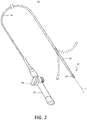
- FIG. 2 A schematic elevational view of catheter 20 is illustrated in FIG. 2 , showing an elongated body that includes an insertion shaft or catheter body 50 having a longitudinal axis "L,” and an intermediate section 52 distal of the catheter body that optionally may be uni- or bi-directionally deflectable off-axis from the catheter body as indicated.
- Proximal of catheter body 50 is control handle 22 that allows an operator to maneuver the catheter as disclosed above, such as by deflecting intermediate section 52 when a steerable embodiment is employed.
- control handle 22 may include deflection knob 54 that is pivoted in a clockwise or counterclockwise direction for deflection in the respective direction.
- steerable designs may be employed, such as the control handles for manipulating multiple control wires as described, for example, in U.S. Patent Nos. 6,468,262 , 6,500,167 , 6,522,933 and 8,617,087 , the entire disclosures of which are incorporated herein by reference.
- Catheter body 50 is flexible, i.e., bendable, but substantially non-compressible along its length and may be of any suitable construction and made of any suitable material.
- an outer wall made of polyurethane or PEBAX® may have an imbedded braided mesh of stainless steel or the like, as is generally known in the art, to increase torsional stiffness of catheter body 50 so that, when the control handle 22 is rotated, the intermediate section 52 will rotate in a corresponding manner.
- the outer diameter of catheter body 50 may be approximately 8 french, and in some embodiments, may be 7 french.
- the thickness of the outer wall of catheter body 50 may be thin enough so that a central lumen may accommodate any desired wires, cables and/or tubes.
- An example of a catheter body construction suitable for use in connection with the present invention is described and depicted in U.S. Patent No. 6,064,905 , the entire disclosure of which is incorporated herein by reference.
- the useful length of the catheter i.e., that portion that can be inserted into the body may vary as desired. In exemplary embodiments, the useful length may range from about 110 cm to about 120 cm.
- the length of the intermediate section 52 may correspond to a relatively small portion of the useful length, such as from about 3.5 cm to about 10 cm, and in some embodiments, from about 5 cm to about 6.5 cm.
- electrode assembly 26 is configured as a generally cylindrical portion that may be disposed over catheter body 50.
- electrode assembly 26 is positioned the distal end 24 of catheter 20 which features a non-conductive, atraumatic tip 54.
- Electrode assembly 26 may be implemented using any suitable flexible circuit architecture, using a non-conductive substrate 56 upon which functional components and their respective leads may be printed, layered or otherwise applied as desired.
- electrode assembly 26 may be formed from a sheet of substrate 56 by bonding opposing edges together to form a single seam 58 as shown in FIG. 4 and create a cylindrical structure to be disposed over catheter body 50.
- each ablation electrode 60 may have a length in the range of 1 mm to 8 mm.
- the length of the electrode is 3 mm.
- the ablation electrode 26 most directly oriented towards the desired treatment area may be energized to form the lesion, while the other ablation electrode 60 is not used, thereby reducing exposure of surrounding areas to RF energy.
- using only one of the two ablation electrodes 60 may allow delivery of energy towards the epicardial surface while minimizing the delivery of energy towards the pericardium, other organs, the nervous system, or other unintended areas. It should be appreciated that the techniques of this disclosure are not limited to the use of two ablation electrodes and any suitable number and radial distribution of electrodes may be employed as discussed below.
- electrode assembly 26 may also comprise microelectrodes 62 positioned within the perimeter of ablation electrodes 60 as shown, or in other embodiments, at locations proximate to the ablation electrodes.
- Microelectrodes 62 may be configured to sense tissue contact, such as by comparing measured electrical characteristics including impedance. Feedback from microelectrodes 62 may be analyzed to determine which ablation electrode 60 should be energized to control the radial delivery of RF energy. In embodiments having more than two ablation electrodes, it may be desirable to energize more than one of the electrodes as warranted.
- Microelectrodes 62 may also be configured as thermocouples or other suitable temperature sensors in order to monitor conditions during ablation.
- Microelectrodes 62 configured as temperature sensors may typically be copper-constantan thermocouples, but other techniques may be used, and may be arrayed at locations around electrode assembly 26, both axially and circumferentially. Any suitable number of microelectrodes 62 may be configured as thermocouples in order to achieve the desired resolution of sensing. As yet another example, microelectrodes 62 may also be configured to record signals for mapping electrical activity of the heart, such as to identify treatment areas to be ablated. Microelectrodes 62 are connected by leads (not shown in these views) running through the length of catheter body 50 to provide their signals to respective components of console 32, such as temperature module 42 and ablation module 44.
- distal end 24 contains other functional components, which are outside the scope of the present disclosure and are therefore omitted for the sake of simplicity.
- the distal end of the catheter may contain steering wires, as well as sensors of other types, such as a position sensor and a force sensor.
- Catheters containing components of these kinds are described, for example, in U.S. Patent No. 8,437,832 and U.S. Patent Publication No. 2011/0130648 , which are incorporated herein by reference.
- FIG. 5 shows a cross sectional view through electrode assembly 26 at one of the ablation electrodes 60 as indicated by line "A" in FIG. 4 .
- This figure shows additional details of the construction of electrode assembly 26 and its flexible electronic circuits.
- Such flex circuits or flexible electronics involve a technology for assembling electronic circuits by mounting electronic devices on flexible plastic substrates, such as polyimide, Liquid Crystal Polymer (LCP), PEEK or transparent conductive polyester film (PET). Additionally, flex circuits can be screen printed silver circuits on polyester. Flexible printed circuits (FPC) may be made with a photolithographic technology.
- FFCs flexible foil circuits or flexible flat cables
- PET layers typically approximately 0.05 mm thick
- an adhesive which is thermosetting, and will be activated during the lamination process.
- Single-sided flexible circuits have a single conductor layer made of either a metal or conductive (metal filled) polymer on a flexible dielectric film.
- Component termination features may be accessible only from one side and holes may be formed in the base film to allow component leads to pass through for interconnection, normally by soldering.
- FIG. 5 One exemplary architecture is shown in FIG. 5 , but any suitable implementation may be employed.
- Substrate 56 may have a first conducting layer from which ablation electrode 60 and microelectrodes 62a, 62b and 62c are formed.
- the electrode layer may be made of any suitable electrically-conductive material, such as palladium, platinum, gold, iridium and combinations and alloys thereof, including, Pd/Pt (e.g., 80% Palladium/20% Platinum) and Pt/Ir (e.g., 90% Platinum/10% Iridium), or the like.
- Lead 64 connects the ablating electrode 60 and runs through catheter body 50 to couple with console 32, for delivery of RF energy supplied by ablation module 44.
- a second conducting layer on the other side of substrate 56 may be used to provide connection to microsensors 62a, 62b and 62c via respective traces 66a, 66b and 66c.
- leads 68a For clarity, only lead 68a is shown, but each trace may be connected to a lead to transmit signals through catheter body 50.
- Each respective trace may be connected to its associated microelectrode through plated holes 70a, 70b and 70c (sometimes referred to as "vias") or other electrically-conductive interconnection through substrate 56.
- depicted lead 64 and a corresponding lead that is also not shown for clarity may convey RF electrical energy from ablation module 44 of console 32, which may control the level of power dissipated, to electrode assembly 26 through catheter body 50.
- microelectrodes 62 are connected by leads 68 running through the length of catheter body 50 to provide their signals to respective components of console 32, such as temperature module 42 and ablation module 44.
- ablation electrode 60 may be selectively energized to ablate myocardial tissue, depending on which electrode is chosen. As discussed above, this may involve using the signals from microelectrodes 62 to determine which ablation electrode 60 is oriented more desirably with respect to the intended treatment area.
- control over the radial delivery of energy may involve energizing a single electrode or a subset of adjacent electrodes. Still further, any desired pattern of electrode activation may be employed in other applications.
- Module 44 may control the level of RF power dissipated via electrode assembly 26.
- electrode assembly 80 may be extended to employ any desired number of ablation electrodes.
- FIG. 6 an alternative embodiment is shown in FIG. 6 , with electrode assembly 80 similarly disposed over catheter body 50.
- electrode assembly 80 features 10 individually controlled ablation electrodes 60 (although only four are visible in this view).
- this embodiment features a pair of microelectrodes 62 for each ablation electrode that are positioned proximally and distally, rather than being within the perimeter of the ablation electrode. Regardless of the exact location of the microelectrodes, it will be appreciated that by associating at least one microelectrode with each ablation electrode, the conditions and characteristics of that ablation electrode may be determined.
- any suitable number of ablation electrodes may be employed with any desired radial distribution.
- four ablation electrodes may be used to provide coverage of quadrants around the circumference of catheter body 50.
- any number of microelectrodes may also be used, depending on the desired sensing resolution or other suitable criteria.
- other distributions may be employed to concentrate a greater number of ablation electrodes in one or more radial areas.
- the ablation electrodes may vary in either size or configuration in other embodiments as desired.
- FIG. 7 schematically depicts an embodiment in which at least two electrode assemblies 90 are positioned relatively proximally and distally along the length of catheter body 50, although still generally towards distal end 24.
- each electrode assembly 90 may have two ablation electrodes 60, oriented approximately 180° with respect to each other in a manner similar to electrode assembly 26.
- each ablation electrode has three microelectrodes 62 in this embodiment, but again, any suitable number may be used as desired. Any number of electrode assemblies 90 may be distributed longitudinally along catheter body 50.
- FIG. 7 Another aspect of this disclosure as depicted in FIG. 7 involves providing electrode assemblies 90 with a plurality of apertures 92 for the perfusion of irrigation fluid, delivered via a lumen (not shown) in catheter 20. Cooling fluid may exit through apertures 92 to help control temperature of the tissue during ablation. When the electrode reaches critical temperatures, denaturation of blood proteins causes coagulum formation. Impedance can then rise and limit current delivery. Moreover, overheating within tissue can cause steam bubble formation (steam "pops") with risk of uncontrolled tissue destruction or undesirable perforation of bodily structures. Thus, the ablation catheters of this disclosure may be irrigated to provide greater control over the temperature of catheter components and the surrounding tissue. As an example of similar techniques, Biosense Webster Inc.
- saline solution or other suitable fluid through the catheter lumen to distal end 24 so that it may flow through apertures 92 during the procedure in order to cool the catheter tip and the tissue.
- other fluids such as heparin, can be transported to the ablation site to cool tissue, reduce coagulation and/or facilitate the formation of deeper lesions. It is understood that other fluids can be delivered, as well, including any diagnostic and therapeutic fluids, such as neuroinhibitors and neuroexcitors for altering the state of ganglionated plexi. Representative details concerning irrigated ablation catheters may be found in commonly-owned U.S. Patent No. 9,675,411 , whose disclosure is incorporated herein by reference in its entirety.
- microelectrodes 62 may be positioned at different locations to measure temperature at the corresponding outer surfaces of electrode assembly 90. As discussed above, such microelectrodes may be within the perimeter of the ablation electrodes or otherwise in proximity, but generally are positioned on the surface of electrode assembly 90 and may be spaced apart from apertures 92. Microelectrodes 62 may thus provide multiple temperature readings that are substantially independent of the cooling fluid temperature, at different locations on electrode assembly 90. The sensor that gives the highest temperature reading may be the one that is in contact with the tissue being ablated, and the temperature measured by this sensor varies linearly with the actual tissue temperature.
- Flow of the irrigation fluid may be generally lower in areas that are in firm contact with the tissue, and the sensors in these areas typically give the highest temperature readings.
- the reading from the "hottest" sensor may thus be used in particular to monitor the tissue temperature and control the applied power and duration of the ablation procedure in order to obtain the desired therapeutic result without excessive tissue damage.
- the temperature readings of the multiple sensors can be combined and interpolated to give a map of temperature over the area of the catheter tip.
Landscapes
- Health & Medical Sciences (AREA)
- Life Sciences & Earth Sciences (AREA)
- Surgery (AREA)
- Engineering & Computer Science (AREA)
- Plasma & Fusion (AREA)
- General Health & Medical Sciences (AREA)
- Otolaryngology (AREA)
- Physics & Mathematics (AREA)
- Veterinary Medicine (AREA)
- Biomedical Technology (AREA)
- Heart & Thoracic Surgery (AREA)
- Medical Informatics (AREA)
- Molecular Biology (AREA)
- Animal Behavior & Ethology (AREA)
- Nuclear Medicine, Radiotherapy & Molecular Imaging (AREA)
- Public Health (AREA)
- Cardiology (AREA)
- Surgical Instruments (AREA)
Abstract
Description
- This invention relates to electrode assemblies for use with electrophysiologic (EP) catheters and related devices for mapping and/or ablation of locations within a patient, such as the heart, in particular, to an ablation catheter having selective radial control over delivery of radio frequency (RF) energy.
- Cardiac arrhythmia, such as atrial fibrillation, occurs when regions of cardiac tissue abnormally conduct electric signals to adjacent tissue, thereby disrupting the normal cardiac cycle and causing asynchronous rhythm. Procedures for treating arrhythmia include surgically disrupting the origin of the signals causing the arrhythmia, as well as disrupting the conducting pathway for such signals. More recently, it has been found that by mapping the electrical properties of the heart and selectively ablating cardiac tissue by application of energy, it is sometimes possible to cease or modify the propagation of unwanted electrical signals from one portion of the heart to another. The ablation process destroys the unwanted electrical pathways by formation of nonconducting lesions. The resulting lesion(s) may isolate irregular electrical signals originating in the one area from spreading and disrupting the patient's heart beat.
- In such procedures, a reference electrode is typically provided and may be attached to the skin of the patient or by means of a second catheter. Radio frequency (RF) current is applied to the tip electrode of the ablating catheter, and current flows through the media that surrounds it, i.e., blood and tissue, toward the reference electrode. The distribution of current depends on the amount of electrode surface in contact with the tissue as compared to blood, which has a higher conductivity than the tissue. Heating of the tissue occurs due to its electrical resistance. The tissue is heated sufficiently to cause cellular destruction in the target tissue resulting in formation of a lesion which is electrically non-conductive.
- As an example of such applications, recent techniques have employed ablation to treat ventricular tachycardia. The technique involves introducing a catheter into the pericardial space, such as by using a subxiphoid pericardial puncture technique. The parietal pericardium is the outer protective layer or sac that encloses the heart which comprises three layers: epicardium, myocardium and endocardium. A pericardial cavity or space separates the parietal pericardium and the epicardium. A small amount of fluid is secreted by tissues of the parietal pericardium to lubricate surfaces so that heart can move freely inside the parietal pericardium. Clearly, adhesion between the parietal pericardium and the epicardium caused by misdirected ablation energy may interfere with muscular contractions of the heart.
- Another potential complication in accessing the epicardium is posed by the phrenic nerve. The phrenic nerve is made up mostly of motor nerve fibers for producing contractions of the diaphragm. In addition, it provides sensory innervation for many components of the mediastinum and pleura, as well as the upper abdomen, especially the liver, and the gall bladder. The right phrenic nerve passes over the right atrium and the left phrenic nerve passes over the left ventricle and pierces the diaphragm separately. Both these nerves supply motor fibers to the diaphragm and sensory fibers to the fibrous pericardium, mediastinal pleura and diaphragmatic peritoneum. Any damage to the phrenic nerve, particularly for senior patients, can cause serious breathing difficulties, especially if the damage is permanent. The lung itself is another organ that is susceptible to damage when ablating the epicardium, although the tissue of the lung can more readily repair itself if burned.
- Conventional ablation catheters have primarily been designed for endocardial uses and do not exhibit optimal delivery of energy for epicardial applications. While such catheters are particularly useful for mapping and ablating in cavities and other tubular regions of or near the heart, the omnidirectional delivery of energy in the epicardium may significantly increase the risk of harmful and unwanted ablation, such as of the parietal pericardium, the phrenic nerve, the lungs and/or other surrounding structures. For example, ring electrodes positioned along a distal portion of the catheter emit energy from their entire circumference, with only a portion being directed at the intended treatment area. Likewise, a distal dome electrode primarily emits energy along the longitudinal axis of the catheter rather than being directed towards the epicardial tissue surface.
- Accordingly, it would be desirable for a catheter to be adapted for the epicardium such that the ablation energy is directed in a radially selective manner to reduce exposure of unwanted regions as well as optimize the ablation by directing energy only to desired locations. Likewise, it would be desirable sense tissue contact or proximity so as to preferentially direct energy towards the intended treatment area. As will be described in the following materials, this disclosure satisfies these and other needs.
- The present disclosure is directed to an electrode assembly configured to be disposed over a distal portion of a catheter body, wherein the electrode assembly has a flexible substrate and a plurality of independently controlled ablation electrodes distributed radially around the electrode assembly.
- In one aspect, two ablation electrodes may be positioned in opposition to each other. Alternatively, the electrode assembly may have more than two ablation electrodes.
- In one aspect, the electrode assembly may be configured as a cylinder. The ablation electrodes may be applied to an outer surface of the substrate.
- In one aspect, at least one microelectrode may be associated with each ablation electrode. At least some of the microelectrodes may be configured to sense tissue contact. Alternatively or in addition, at least some of the microelectrodes may be configured to sense temperature. Further, at least some of the microelectrodes may be positioned within a perimeter of at least one of the ablation electrodes.
- In one aspect, each ablation electrode may have a plurality of apertures configured to perfuse irrigation fluid.
- This disclosure is also directed to a catheter with an elongated catheter body having proximal and distal ends and an electrode assembly, wherein the electrode assembly is disposed over a distal portion of the catheter body and wherein the electrode assembly has a flexible substrate with a plurality of independently controlled ablation electrodes distributed radially around the electrode assembly. In one aspect, a plurality of electrode assemblies may be distributed longitudinally along the catheter body. Each electrode assembly may have two ablation electrodes positioned in opposition to each other.
- This disclosure also includes a method for constructing an electrode assembly to be disposed over a catheter body. The method may include providing a flexible substrate having opposing edges, applying a plurality of independently controlled ablation electrodes to a surface of the flexible substrate, and joining the opposing edges of the substrate to form a cylinder, wherein the ablation electrodes are distributed radially around the cylinder.
- In one aspect, the electrode assembly comprises two ablation electrodes positioned in opposition to each other. The method may also include applying at least one microelectrode associated with each ablation electrode to the surface of the substrate. Further, a plurality of apertures configured to perfuse irrigation fluid may be formed in the substrate and the applied ablation electrodes.
- This disclosure further includes a method for the ablation of a portion of tissue of a patient by an operator. The method may involve inserting a catheter into the patient, wherein the catheter has an elongated body and an electrode assembly disposed over a distal portion of the elongated body, wherein the electrode assembly comprises a plurality of independently controlled ablation electrodes distributed radially around the electrode assembly. The catheter may be connected to a system controller capable of selectively delivering power at least one of the ablation electrodes and power to the at least one ablation electrode may be controlled to ablate tissue.
- In one aspect, controlling the power to the at least one ablation electrode may cause the electrode assembly to preferentially emit energy in a radial direction.
- In one aspect, signals may be received from a plurality of microelectrodes of the electrode assembly, wherein at least one microelectrode is associated with each ablation electrode and is configured to sense tissue. The power may be controlled to the at least one ablation electrode is based at least in part on the received signals.
- Further features and advantages will become apparent from the following and more particular description of the preferred embodiments of the disclosure, as illustrated in the accompanying drawings, and in which like referenced characters generally refer to the same parts or elements throughout the views, and in which:
-
FIG. 1 is a schematic view of an ablation system in accordance with an embodiment of the present invention. -
FIG. 2 is a perspective view of a catheter having selective radial energy delivery in accordance with an embodiment of the present invention. -
FIG. 3 is a schematic, elevational view of a distal end of the catheter ofFIG. 2 , showing an electrode assembly with radially distributed ablation electrodes in accordance with an embodiment of the present invention. -
FIG. 4 is a schematic, elevational view rotated 90° from the view shown inFIG. 3 . -
FIG. 5 is a partial, schematic cross section of an electrode assembly formed from a flexible substrate in accordance with an embodiment of the present invention. -
FIG. 6 is a schematic, elevational view of a distal end of a catheter having an alternative electrode assembly with radially distributed ablation electrodes in accordance with an embodiment of the present invention. -
FIG. 7 is a schematic, elevational view of a distal end of a catheter having an multiple electrode assemblies distributed longitudinally along the catheter body in accordance with an embodiment of the present invention. - At the outset, it is to be understood that this disclosure is not limited to particularly exemplified materials, architectures, routines, methods or structures as such may vary. Thus, although a number of such options, similar or equivalent to those described herein, can be used in the practice or embodiments of this disclosure, the preferred materials and methods are described herein.
- It is also to be understood that the terminology used herein is for the purpose of describing particular embodiments of this disclosure only and is not intended to be limiting.
- The detailed description set forth below in connection with the appended drawings is intended as a description of exemplary embodiments of the present disclosure and is not intended to represent the only exemplary embodiments in which the present disclosure can be practiced. The term "exemplary" used throughout this description means "serving as an example, instance, or illustration," and should not necessarily be construed as preferred or advantageous over other exemplary embodiments. The detailed description includes specific details for the purpose of providing a thorough understanding of the exemplary embodiments of the specification. It will be apparent to those skilled in the art that the exemplary embodiments of the specification may be practiced without these specific details. In some instances, well known structures and devices are shown in block diagram form in order to avoid obscuring the novelty of the exemplary embodiments presented herein.
- For purposes of convenience and clarity only, directional terms, such as top, bottom, left, right, up, down, over, above, below, beneath, rear, back, and front, may be used with respect to the accompanying drawings. These and similar directional terms should not be construed to limit the scope of the disclosure in any manner.
- Unless defined otherwise, all technical and scientific terms used herein have the same meaning as commonly understood by one having ordinary skill in the art to which the disclosure pertains.
- Finally, as used in this specification and the appended claims, the singular forms "a", "an" and "the" include plural referents unless the content clearly dictates otherwise.
- As noted above, certain types of electrical activity within the heart chamber may not be cyclical. For example, ventricular tachycardia originating in scars in the wall of the ventricle may be a result of infarcts. Such electrical activity is random from beat to beat. RF energy may be delivered to selected treatment areas of the epicardial tissue for ablation based therapies, including for example, isolation of a source of irregular electrical signals by blocking electrical conduction. Correspondingly, one or more electrode assemblies, each with a plurality of electrodes, may be used to deliver ablation energy in a radially selective manner. Further, each electrode assembly may have microelectrodes for tissue sensing, measurement of temperature during the ablation temperature, as well as other suitable purposes.
-
FIG. 1 is a schematic illustration of an invasive medicalprocedure using system 12, according to an embodiment of the present invention. The procedure is performed by a medical professional,operator 14, and, by way of example, the procedure in the description hereinbelow is assumed to comprise ablation of a portion of atissue 16 of the heart of ahuman patient 18, such as at an area of the epicardial surface from within the pericardial cavity as discussed above. However, it will be understood that embodiments of the present invention are not applicable to this specific procedure alone and may include substantially any procedure on biological tissue or on non-biological material. - In order to perform the ablation,
operator 14 inserts acatheter 20 into a lumen of the patient, usinghandle 22, so that adistal end 24 of the catheter enters the heart of the patient.Distal end 24 comprises at least anelectrode assembly 26 for delivering ablation energy to intended locations of the heart in a radially controlled manner.Catheter 20 has aproximal end 28 for connection to associated equipment as described below.Distal end 24 and in particular,electrode assembly 26, of the catheter is described in more detail with reference toFIGs. 3, 4 and5 . -
System 12 is controlled by asystem processor 30, which is located in an operatingconsole 32 of the system.Console 32 comprisescontrols 34 which are used by professional 14 to communicate with the processor. During the procedure,processor 30 typically tracks a location and an orientation ofdistal end 24 of the catheter, using any method known in the art. For example,processor 30 may use a magnetic tracking method, wherein magnetic transmitters external topatient 18 generate signals in coils positioned in the distal end. The CARTO® system referenced above uses such a tracking method and additional details may be found inU.S. Patent Nos. 5,391,199 ,6,690,963 ,6,484,118 ,6,239,724 ,6,618,612 ,6,332,089 ,6,690,963 ,7,729,742 , inPCT Patent Publication WO 96/05768 U.S. Patent Publication No. 2004/0068178 A1 , whose disclosures are all incorporated herein by reference. - The software for
processor 30 may be downloaded to the processor in electronic form, over a network, for example. Alternatively or additionally, the software may be provided on non-transitory tangible media, such as optical, magnetic, or electronic storage media. The track ofdistal end 24 is typically displayed on a three-dimensional representation 36 of theheart 16 ofpatient 18 on ascreen 38. In order to operatesystem 12,processor 30 communicates with amemory 40, which has a number of modules used by the processor to operate the apparatus. Thus,memory 40 comprises atemperature module 42 and anablation module 44, for example, and typically comprises other modules, such as a force module for measuring the force onend 24, a tracking module for operating the tracking method used byprocessor 30, and an irrigation module allowing the processor to control irrigation provided fordistal end 24. For simplicity, such other modules, which may comprise hardware as well as software elements, are not illustrated inFIG. 1 .Processor 30 typically uses results of measurements of temperature acquired bymodule 42 to display on screen 38 atemperature distribution map 46. - A schematic elevational view of
catheter 20 is illustrated inFIG. 2 , showing an elongated body that includes an insertion shaft orcatheter body 50 having a longitudinal axis "L," and anintermediate section 52 distal of the catheter body that optionally may be uni- or bi-directionally deflectable off-axis from the catheter body as indicated. Proximal ofcatheter body 50 iscontrol handle 22 that allows an operator to maneuver the catheter as disclosed above, such as by deflectingintermediate section 52 when a steerable embodiment is employed. For example, control handle 22 may includedeflection knob 54 that is pivoted in a clockwise or counterclockwise direction for deflection in the respective direction. In other embodiments, other steerable designs may be employed, such as the control handles for manipulating multiple control wires as described, for example, inU.S. Patent Nos. 6,468,262 ,6,500,167 ,6,522,933 and8,617,087 , the entire disclosures of which are incorporated herein by reference. -
Catheter body 50 is flexible, i.e., bendable, but substantially non-compressible along its length and may be of any suitable construction and made of any suitable material. In one aspect, an outer wall made of polyurethane or PEBAX® (polyether block amide) may have an imbedded braided mesh of stainless steel or the like, as is generally known in the art, to increase torsional stiffness ofcatheter body 50 so that, when the control handle 22 is rotated, theintermediate section 52 will rotate in a corresponding manner. Depending upon the intended use, the outer diameter ofcatheter body 50 may be approximately 8 french, and in some embodiments, may be 7 french. Likewise, the thickness of the outer wall ofcatheter body 50 may be thin enough so that a central lumen may accommodate any desired wires, cables and/or tubes. An example of a catheter body construction suitable for use in connection with the present invention is described and depicted inU.S. Patent No. 6,064,905 , the entire disclosure of which is incorporated herein by reference. The useful length of the catheter, i.e., that portion that can be inserted into the body may vary as desired. In exemplary embodiments, the useful length may range from about 110 cm to about 120 cm. The length of theintermediate section 52 may correspond to a relatively small portion of the useful length, such as from about 3.5 cm to about 10 cm, and in some embodiments, from about 5 cm to about 6.5 cm. - Details regarding one embodiment of the
distal end 24 ofcatheter 20 are illustrated inFIGs. 3, 4 and5 . As indicated,electrode assembly 26 is configured as a generally cylindrical portion that may be disposed overcatheter body 50. In this embodiment,electrode assembly 26 is positioned thedistal end 24 ofcatheter 20 which features a non-conductive,atraumatic tip 54.Electrode assembly 26 may be implemented using any suitable flexible circuit architecture, using anon-conductive substrate 56 upon which functional components and their respective leads may be printed, layered or otherwise applied as desired. For example,electrode assembly 26 may be formed from a sheet ofsubstrate 56 by bonding opposing edges together to form asingle seam 58 as shown inFIG. 4 and create a cylindrical structure to be disposed overcatheter body 50. - The two elevational views shown in
FIGs. 3 and 4 are rotated 90° with respect to each other about the longitudinal axis "L," to illustrate the radial distribution of twoablation electrodes 60 representative of this embodiment. As may be seen, theablation electrodes 60 are positioned in opposition to each other on either side ofelectrode assembly 26, in an approximately 180° orientation. It will also be appreciated thatdistal end 24 may have a non-linear configuration during use, either due to directional steering control or due to a pre-shaped end. The positioning of ablation electrodes may correspondingly follow the bias of the catheter representing the deflection curve so that one of the ablation electrodes may preferentially orient towards the desired treatment area. Generally, eachablation electrode 60 may have a length in the range of 1 mm to 8 mm. In an embodiment, the length of the electrode is 3 mm. With this configuration, theablation electrode 26 most directly oriented towards the desired treatment area may be energized to form the lesion, while theother ablation electrode 60 is not used, thereby reducing exposure of surrounding areas to RF energy. In the context of an epicardial procedure similar to that described above, using only one of the twoablation electrodes 60 may allow delivery of energy towards the epicardial surface while minimizing the delivery of energy towards the pericardium, other organs, the nervous system, or other unintended areas. It should be appreciated that the techniques of this disclosure are not limited to the use of two ablation electrodes and any suitable number and radial distribution of electrodes may be employed as discussed below. - As shown,
electrode assembly 26 may also comprisemicroelectrodes 62 positioned within the perimeter ofablation electrodes 60 as shown, or in other embodiments, at locations proximate to the ablation electrodes.Microelectrodes 62 may be configured to sense tissue contact, such as by comparing measured electrical characteristics including impedance. Feedback frommicroelectrodes 62 may be analyzed to determine whichablation electrode 60 should be energized to control the radial delivery of RF energy. In embodiments having more than two ablation electrodes, it may be desirable to energize more than one of the electrodes as warranted.Microelectrodes 62 may also be configured as thermocouples or other suitable temperature sensors in order to monitor conditions during ablation.Microelectrodes 62 configured as temperature sensors may typically be copper-constantan thermocouples, but other techniques may be used, and may be arrayed at locations aroundelectrode assembly 26, both axially and circumferentially. Any suitable number ofmicroelectrodes 62 may be configured as thermocouples in order to achieve the desired resolution of sensing. As yet another example, microelectrodes 62 may also be configured to record signals for mapping electrical activity of the heart, such as to identify treatment areas to be ablated.Microelectrodes 62 are connected by leads (not shown in these views) running through the length ofcatheter body 50 to provide their signals to respective components ofconsole 32, such astemperature module 42 andablation module 44. - Typically,
distal end 24 contains other functional components, which are outside the scope of the present disclosure and are therefore omitted for the sake of simplicity. For example, the distal end of the catheter may contain steering wires, as well as sensors of other types, such as a position sensor and a force sensor. Catheters containing components of these kinds are described, for example, inU.S. Patent No. 8,437,832 andU.S. Patent Publication No. 2011/0130648 , which are incorporated herein by reference. - Reference is now additionally made to
FIG. 5 , which shows a cross sectional view throughelectrode assembly 26 at one of theablation electrodes 60 as indicated by line "A" inFIG. 4 . This figure shows additional details of the construction ofelectrode assembly 26 and its flexible electronic circuits. Such flex circuits or flexible electronics involve a technology for assembling electronic circuits by mounting electronic devices on flexible plastic substrates, such as polyimide, Liquid Crystal Polymer (LCP), PEEK or transparent conductive polyester film (PET). Additionally, flex circuits can be screen printed silver circuits on polyester. Flexible printed circuits (FPC) may be made with a photolithographic technology. An alternative way of making flexible foil circuits or flexible flat cables (FFCs) is laminating very thin (approximately 0.07 mm) copper strips in between two layers of PET. These PET layers, typically approximately 0.05 mm thick, are coated with an adhesive which is thermosetting, and will be activated during the lamination process. Single-sided flexible circuits have a single conductor layer made of either a metal or conductive (metal filled) polymer on a flexible dielectric film. Component termination features may be accessible only from one side and holes may be formed in the base film to allow component leads to pass through for interconnection, normally by soldering. One exemplary architecture is shown inFIG. 5 , but any suitable implementation may be employed.Substrate 56 may have a first conducting layer from whichablation electrode 60 andmicroelectrodes Lead 64 connects the ablatingelectrode 60 and runs throughcatheter body 50 to couple withconsole 32, for delivery of RF energy supplied byablation module 44. A second conducting layer on the other side ofsubstrate 56 may be used to provide connection tomicrosensors respective traces catheter body 50. Each respective trace may be connected to its associated microelectrode through platedholes substrate 56. Thus, depictedlead 64 and a corresponding lead that is also not shown for clarity may convey RF electrical energy fromablation module 44 ofconsole 32, which may control the level of power dissipated, toelectrode assembly 26 throughcatheter body 50. Similarly, microelectrodes 62 are connected by leads 68 running through the length ofcatheter body 50 to provide their signals to respective components ofconsole 32, such astemperature module 42 andablation module 44. Correspondingly, eitherablation electrode 60 may be selectively energized to ablate myocardial tissue, depending on which electrode is chosen. As discussed above, this may involve using the signals frommicroelectrodes 62 to determine whichablation electrode 60 is oriented more desirably with respect to the intended treatment area. Once again, in embodiments having more than two ablation electrodes, control over the radial delivery of energy may involve energizing a single electrode or a subset of adjacent electrodes. Still further, any desired pattern of electrode activation may be employed in other applications.Module 44 may control the level of RF power dissipated viaelectrode assembly 26. - As noted above, the techniques of this disclosure may be extended to employ any desired number of ablation electrodes. For example, an alternative embodiment is shown in
FIG. 6 , withelectrode assembly 80 similarly disposed overcatheter body 50. In the depicted embodiment,electrode assembly 80 features 10 individually controlled ablation electrodes 60 (although only four are visible in this view). Further, this embodiment features a pair ofmicroelectrodes 62 for each ablation electrode that are positioned proximally and distally, rather than being within the perimeter of the ablation electrode. Regardless of the exact location of the microelectrodes, it will be appreciated that by associating at least one microelectrode with each ablation electrode, the conditions and characteristics of that ablation electrode may be determined. In other embodiments, any suitable number of ablation electrodes may be employed with any desired radial distribution. For example, four ablation electrodes may be used to provide coverage of quadrants around the circumference ofcatheter body 50. Equally, any number of microelectrodes may also be used, depending on the desired sensing resolution or other suitable criteria. Similarly, although the embodiments depicted in this disclosure have generally even radial distribution, other distributions may be employed to concentrate a greater number of ablation electrodes in one or more radial areas. Likewise, even though the depicted ablation electrodes have generally the same size and configuration, the ablation electrodes may vary in either size or configuration in other embodiments as desired. - In another aspect, multiple electrode assemblies may be employed as well. For example,
FIG. 7 schematically depicts an embodiment in which at least twoelectrode assemblies 90 are positioned relatively proximally and distally along the length ofcatheter body 50, although still generally towardsdistal end 24. As shown, eachelectrode assembly 90 may have twoablation electrodes 60, oriented approximately 180° with respect to each other in a manner similar toelectrode assembly 26. Likewise, each ablation electrode has threemicroelectrodes 62 in this embodiment, but again, any suitable number may be used as desired. Any number ofelectrode assemblies 90 may be distributed longitudinally alongcatheter body 50. - Another aspect of this disclosure as depicted in
FIG. 7 involves providingelectrode assemblies 90 with a plurality ofapertures 92 for the perfusion of irrigation fluid, delivered via a lumen (not shown) incatheter 20. Cooling fluid may exit throughapertures 92 to help control temperature of the tissue during ablation. When the electrode reaches critical temperatures, denaturation of blood proteins causes coagulum formation. Impedance can then rise and limit current delivery. Moreover, overheating within tissue can cause steam bubble formation (steam "pops") with risk of uncontrolled tissue destruction or undesirable perforation of bodily structures. Thus, the ablation catheters of this disclosure may be irrigated to provide greater control over the temperature of catheter components and the surrounding tissue. As an example of similar techniques, Biosense Webster Inc. (Diamond Bar, Calif.) offers the ThermoCool® irrigated-tip catheter for use with its CARTO® integrated mapping and ablation system. A pump coupled to the catheter delivers saline solution or other suitable fluid through the catheter lumen todistal end 24 so that it may flow throughapertures 92 during the procedure in order to cool the catheter tip and the tissue. In addition to saline, other fluids such as heparin, can be transported to the ablation site to cool tissue, reduce coagulation and/or facilitate the formation of deeper lesions. It is understood that other fluids can be delivered, as well, including any diagnostic and therapeutic fluids, such as neuroinhibitors and neuroexcitors for altering the state of ganglionated plexi. Representative details concerning irrigated ablation catheters may be found in commonly-ownedU.S. Patent No. 9,675,411 - Likewise, it may also be desirable to accurately monitor temperature to help control the rate of irrigation. Notably, microelectrodes 62, configured as temperature sensors, may be positioned at different locations to measure temperature at the corresponding outer surfaces of
electrode assembly 90. As discussed above, such microelectrodes may be within the perimeter of the ablation electrodes or otherwise in proximity, but generally are positioned on the surface ofelectrode assembly 90 and may be spaced apart fromapertures 92.Microelectrodes 62 may thus provide multiple temperature readings that are substantially independent of the cooling fluid temperature, at different locations onelectrode assembly 90. The sensor that gives the highest temperature reading may be the one that is in contact with the tissue being ablated, and the temperature measured by this sensor varies linearly with the actual tissue temperature. Flow of the irrigation fluid may be generally lower in areas that are in firm contact with the tissue, and the sensors in these areas typically give the highest temperature readings. In some applications, the reading from the "hottest" sensor may thus be used in particular to monitor the tissue temperature and control the applied power and duration of the ablation procedure in order to obtain the desired therapeutic result without excessive tissue damage. Alternatively or additionally, the temperature readings of the multiple sensors can be combined and interpolated to give a map of temperature over the area of the catheter tip. - The preceding description has been presented with reference to presently disclosed embodiments of the invention. Workers skilled in the art and technology to which this invention pertains will appreciate that alterations and changes in the described structure may be practiced without meaningfully departing from the principal, spirit and scope of this invention. As understood by one of ordinary skill in the art, the drawings are not necessarily to scale. Accordingly, the foregoing description should not be read as pertaining only to the precise structures described and illustrated in the accompanying drawings, but rather should be read consistent with and as support to the following claims which are to have their fullest and fair scope.
-
- 1. A method for the ablation of a portion of tissue of a patient by an operator comprising:
- inserting a catheter into the patient, wherein the catheter comprises:
- an elongated body; and
- an electrode assembly disposed over a distal portion of the elongated body, wherein the electrode assembly comprises a plurality of independently controlled ablation electrodes distributed radially around the electrode assembly;
- connecting the catheter to a system controller capable of selectively delivering power at least one of the ablation electrodes; and
- controlling the power to the at least one ablation electrode to ablate tissue.
- inserting a catheter into the patient, wherein the catheter comprises:
- 2. The method of aspect 1, wherein controlling the power to the at least one ablation electrode causes the electrode assembly to preferentially emit energy in a radial direction.
- 3. The method of aspect 1, further comprising receiving signals from a plurality of microelectrodes of the electrode assembly, wherein at least one microelectrode is associated with each ablation electrode and is configured to sense tissue and wherein controlling the power to the at least one ablation electrode is based at least in part on the received signals.
Claims (15)
- An electrode assembly configured to be disposed over a distal portion of a catheter body, wherein the electrode assembly comprises a flexible substrate and a plurality of independently controlled ablation electrodes distributed radially around the electrode assembly.
- The electrode assembly of claim 1, comprising more than two ablation electrodes.
- The electrode assembly of claim 1, wherein the electrode assembly is configured as a cylinder.
- The electrode assembly of claim 3, wherein the ablation electrodes are applied to an outer surface of the substrate.
- The electrode assembly of claim 1, further comprising at least one microelectrode associated with each ablation electrode.
- The electrode assembly of claim 5, wherein at least some of the microelectrodes are configured to sense tissue contact, or to sense temperature.
- The electrode assembly of claim 5, wherein at least some of the microelectrodes are positioned within a perimeter of at least one of the ablation electrodes.
- The electrode assembly of claim 1, wherein each ablation electrode has a plurality of apertures configured to perfuse irrigation fluid.
- A catheter comprising an elongated catheter body having proximal and distal ends and an electrode assembly, wherein the electrode assembly is disposed over a distal portion of the catheter body and wherein the electrode assembly comprises a flexible substrate and a plurality of independently controlled ablation electrodes distributed radially around the electrode assembly.
- The catheter of claim 9, further comprising a plurality of electrode assemblies distributed longitudinally along the catheter body.
- The electrode assembly of claim 1 or the catheter of claim 10, wherein each electrode assembly comprises two ablation electrodes positioned in opposition to each other.
- A method for constructing an electrode assembly to be disposed over a catheter body, comprising providing a flexible substrate having opposing edges, applying a plurality of independently controlled ablation electrodes to a surface of the flexible substrate, and joining the opposing edges of the substrate to form a cylinder, wherein the ablation electrodes are distributed radially around the cylinder.
- The method of claim 12, wherein the electrode assembly comprises two ablation electrodes positioned in opposition to each other.
- The method of claim 12, further comprising applying at least one microelectrode associated with each ablation electrode to the surface of the substrate.
- The method of claim 12, further comprising forming a plurality of apertures configured to perfuse irrigation fluid in the substrate and the applied ablation electrodes.
Applications Claiming Priority (1)
| Application Number | Priority Date | Filing Date | Title |
|---|---|---|---|
| US15/969,579 US11864825B2 (en) | 2018-05-02 | 2018-05-02 | Ablation catheter with selective radial energy delivery |
Publications (1)
| Publication Number | Publication Date |
|---|---|
| EP3563787A1 true EP3563787A1 (en) | 2019-11-06 |
Family
ID=66349448
Family Applications (1)
| Application Number | Title | Priority Date | Filing Date |
|---|---|---|---|
| EP19172110.9A Pending EP3563787A1 (en) | 2018-05-02 | 2019-05-01 | Ablation catheter with selective radial energy delivery |
Country Status (7)
| Country | Link |
|---|---|
| US (1) | US11864825B2 (en) |
| EP (1) | EP3563787A1 (en) |
| JP (1) | JP7387284B2 (en) |
| CN (1) | CN110432976A (en) |
| AU (1) | AU2019202883A1 (en) |
| CA (1) | CA3041485A1 (en) |
| IL (1) | IL266110B1 (en) |
Families Citing this family (4)
| Publication number | Priority date | Publication date | Assignee | Title |
|---|---|---|---|---|
| US11903639B2 (en) * | 2020-04-17 | 2024-02-20 | Biosense Webster (Israel) Ltd. | Flexible distal-end assembly with double-sided electrode array and irrigation |
| WO2021229876A1 (en) * | 2020-05-14 | 2021-11-18 | 株式会社カネカ | Balloon catheter and balloon catheter system having same |
| CN113616325B (en) * | 2021-09-13 | 2023-03-24 | 心航路医学科技(广州)有限公司 | Miniature pulse ablation device |
| US20240164834A1 (en) * | 2022-11-18 | 2024-05-23 | St. Jude Medical, Cardiology Division, Inc. | Systems and methods for catheters having combined mapping and ablation capabilities |
Citations (19)
| Publication number | Priority date | Publication date | Assignee | Title |
|---|---|---|---|---|
| US5391199A (en) | 1993-07-20 | 1995-02-21 | Biosense, Inc. | Apparatus and method for treating cardiac arrhythmias |
| WO1996005768A1 (en) | 1994-08-19 | 1996-02-29 | Biosense, Inc. | Medical diagnosis, treatment and imaging systems |
| US6064905A (en) | 1998-06-18 | 2000-05-16 | Cordis Webster, Inc. | Multi-element tip electrode mapping catheter |
| US6239724B1 (en) | 1997-12-30 | 2001-05-29 | Remon Medical Technologies, Ltd. | System and method for telemetrically providing intrabody spatial position |
| US6332089B1 (en) | 1996-02-15 | 2001-12-18 | Biosense, Inc. | Medical procedures and apparatus using intrabody probes |
| US6468262B1 (en) | 1999-12-02 | 2002-10-22 | Embol-X, Inc. | Buoyant tip aspiration catheter and methods of use |
| US6484118B1 (en) | 2000-07-20 | 2002-11-19 | Biosense, Inc. | Electromagnetic position single axis system |
| US6500167B1 (en) | 1997-09-05 | 2002-12-31 | Biosense Webster, Inc. | Omni-directional steerable catheter |
| US6522933B2 (en) | 2001-03-30 | 2003-02-18 | Biosense, Webster, Inc. | Steerable catheter with a control handle having a pulley mechanism |
| US6618612B1 (en) | 1996-02-15 | 2003-09-09 | Biosense, Inc. | Independently positionable transducers for location system |
| US6690963B2 (en) | 1995-01-24 | 2004-02-10 | Biosense, Inc. | System for determining the location and orientation of an invasive medical instrument |
| US20040068178A1 (en) | 2002-09-17 | 2004-04-08 | Assaf Govari | High-gradient recursive locating system |
| US20070219551A1 (en) * | 2003-09-22 | 2007-09-20 | Honour Kirk S | Medical device with flexible printed circuit |
| US7729742B2 (en) | 2001-12-21 | 2010-06-01 | Biosense, Inc. | Wireless position sensor |
| US20110130648A1 (en) | 2009-11-30 | 2011-06-02 | Christopher Thomas Beeckler | Catheter with pressure measuring tip |
| US8437832B2 (en) | 2008-06-06 | 2013-05-07 | Biosense Webster, Inc. | Catheter with bendable tip |
| US8617087B2 (en) | 2010-12-03 | 2013-12-31 | Biosense Webster, Inc. | Control handle with rotational cam mechanism for contraction/deflection of medical device |
| US9675411B2 (en) | 2008-07-15 | 2017-06-13 | Biosense Webster, Inc. | Catheter with perforated tip |
| US20170312022A1 (en) * | 2016-04-28 | 2017-11-02 | Biosense Webster (Israel) Ltd. | Irrigated balloon catheter with flexible circuit electrode assembly |
Family Cites Families (20)
| Publication number | Priority date | Publication date | Assignee | Title |
|---|---|---|---|---|
| WO1995010978A1 (en) * | 1993-10-19 | 1995-04-27 | Ep Technologies, Inc. | Segmented electrode assemblies for ablation of tissue |
| US5462545A (en) * | 1994-01-31 | 1995-10-31 | New England Medical Center Hospitals, Inc. | Catheter electrodes |
| US8496653B2 (en) | 2007-04-23 | 2013-07-30 | Boston Scientific Scimed, Inc. | Thrombus removal |
| US8103327B2 (en) | 2007-12-28 | 2012-01-24 | Rhythmia Medical, Inc. | Cardiac mapping catheter |
| US8954161B2 (en) | 2012-06-01 | 2015-02-10 | Advanced Cardiac Therapeutics, Inc. | Systems and methods for radiometrically measuring temperature and detecting tissue contact prior to and during tissue ablation |
| US9655677B2 (en) | 2010-05-12 | 2017-05-23 | Shifamed Holdings, Llc | Ablation catheters including a balloon and electrodes |
| US10517667B2 (en) * | 2014-05-16 | 2019-12-31 | Biosense Webster (Israel) Ltd. | Catheter tip with microelectrodes |
| US8900228B2 (en) * | 2011-09-01 | 2014-12-02 | Biosense Webster (Israel) Ltd. | Catheter adapted for direct tissue contact and pressure sensing |
| JP5898336B2 (en) | 2011-12-23 | 2016-04-06 | べシックス・バスキュラー・インコーポレイテッド | Device comprising an electrode pad with an expandable balloon and a heat sensing device |
| US9023036B2 (en) | 2012-12-07 | 2015-05-05 | Biosense Webster (Israel) Ltd. | Lasso catheter with tip electrode |
| EP3777703B1 (en) | 2013-02-08 | 2023-04-05 | Acutus Medical Inc. | Expandable catheter assembly with flexible printed circuit board |
| CN105658163B (en) * | 2013-10-25 | 2020-08-18 | 波士顿科学国际有限公司 | Embedded thermocouple in denervation flexible circuit |
| US9743981B2 (en) | 2013-10-25 | 2017-08-29 | Covidien Lp | Unfurling electrode devices with spring |
| EP3091922B1 (en) | 2014-01-06 | 2018-10-17 | Boston Scientific Scimed, Inc. | Tear resistant flex circuit assembly |
| US9956035B2 (en) * | 2014-03-27 | 2018-05-01 | Biosense Webster (Israel) Ltd. | Temperature measurement in catheter |
| US10111623B2 (en) | 2014-09-12 | 2018-10-30 | X-Rhythm, Llc | Multi-electrode mapping catheter |
| US20160228061A1 (en) * | 2015-02-10 | 2016-08-11 | Cathprint Ab | Low profile medical device with integrated flexible circuit and methods of making the same |
| US9636164B2 (en) | 2015-03-25 | 2017-05-02 | Advanced Cardiac Therapeutics, Inc. | Contact sensing systems and methods |
| JP2018535739A (en) | 2015-11-16 | 2018-12-06 | アパマ・メディカル・インコーポレーテッド | Energy delivery device |
| US20170156791A1 (en) | 2015-12-08 | 2017-06-08 | Biosense Webster (Israel) Ltd. | Ablating and sensing electrodes |
-
2018
- 2018-05-02 US US15/969,579 patent/US11864825B2/en active Active
-
2019
- 2019-04-17 IL IL266110A patent/IL266110B1/en unknown
- 2019-04-24 AU AU2019202883A patent/AU2019202883A1/en not_active Abandoned
- 2019-04-26 JP JP2019085218A patent/JP7387284B2/en active Active
- 2019-04-26 CA CA3041485A patent/CA3041485A1/en not_active Abandoned
- 2019-04-30 CN CN201910362146.3A patent/CN110432976A/en active Pending
- 2019-05-01 EP EP19172110.9A patent/EP3563787A1/en active Pending
Patent Citations (19)
| Publication number | Priority date | Publication date | Assignee | Title |
|---|---|---|---|---|
| US5391199A (en) | 1993-07-20 | 1995-02-21 | Biosense, Inc. | Apparatus and method for treating cardiac arrhythmias |
| WO1996005768A1 (en) | 1994-08-19 | 1996-02-29 | Biosense, Inc. | Medical diagnosis, treatment and imaging systems |
| US6690963B2 (en) | 1995-01-24 | 2004-02-10 | Biosense, Inc. | System for determining the location and orientation of an invasive medical instrument |
| US6332089B1 (en) | 1996-02-15 | 2001-12-18 | Biosense, Inc. | Medical procedures and apparatus using intrabody probes |
| US6618612B1 (en) | 1996-02-15 | 2003-09-09 | Biosense, Inc. | Independently positionable transducers for location system |
| US6500167B1 (en) | 1997-09-05 | 2002-12-31 | Biosense Webster, Inc. | Omni-directional steerable catheter |
| US6239724B1 (en) | 1997-12-30 | 2001-05-29 | Remon Medical Technologies, Ltd. | System and method for telemetrically providing intrabody spatial position |
| US6064905A (en) | 1998-06-18 | 2000-05-16 | Cordis Webster, Inc. | Multi-element tip electrode mapping catheter |
| US6468262B1 (en) | 1999-12-02 | 2002-10-22 | Embol-X, Inc. | Buoyant tip aspiration catheter and methods of use |
| US6484118B1 (en) | 2000-07-20 | 2002-11-19 | Biosense, Inc. | Electromagnetic position single axis system |
| US6522933B2 (en) | 2001-03-30 | 2003-02-18 | Biosense, Webster, Inc. | Steerable catheter with a control handle having a pulley mechanism |
| US7729742B2 (en) | 2001-12-21 | 2010-06-01 | Biosense, Inc. | Wireless position sensor |
| US20040068178A1 (en) | 2002-09-17 | 2004-04-08 | Assaf Govari | High-gradient recursive locating system |
| US20070219551A1 (en) * | 2003-09-22 | 2007-09-20 | Honour Kirk S | Medical device with flexible printed circuit |
| US8437832B2 (en) | 2008-06-06 | 2013-05-07 | Biosense Webster, Inc. | Catheter with bendable tip |
| US9675411B2 (en) | 2008-07-15 | 2017-06-13 | Biosense Webster, Inc. | Catheter with perforated tip |
| US20110130648A1 (en) | 2009-11-30 | 2011-06-02 | Christopher Thomas Beeckler | Catheter with pressure measuring tip |
| US8617087B2 (en) | 2010-12-03 | 2013-12-31 | Biosense Webster, Inc. | Control handle with rotational cam mechanism for contraction/deflection of medical device |
| US20170312022A1 (en) * | 2016-04-28 | 2017-11-02 | Biosense Webster (Israel) Ltd. | Irrigated balloon catheter with flexible circuit electrode assembly |
Also Published As
| Publication number | Publication date |
|---|---|
| AU2019202883A1 (en) | 2019-11-21 |
| JP2019193790A (en) | 2019-11-07 |
| CN110432976A (en) | 2019-11-12 |
| US11864825B2 (en) | 2024-01-09 |
| IL266110A (en) | 2019-07-31 |
| CA3041485A1 (en) | 2019-11-02 |
| JP7387284B2 (en) | 2023-11-28 |
| IL266110B1 (en) | 2024-04-01 |
| US20190336205A1 (en) | 2019-11-07 |
Similar Documents
| Publication | Publication Date | Title |
|---|---|---|
| US20200261152A1 (en) | Irrigated balloon catheter with flexible circuit electrode assembly | |
| US10987163B2 (en) | Treatment of atrial fibrillation using high-frequency pacing and ablation of renal nerves | |
| EP3563787A1 (en) | Ablation catheter with selective radial energy delivery | |
| EP2380518B1 (en) | Dual-purpose lasso catheter with irrigation using circumferentially arranged ring bump electrodes | |
| CN107468329B (en) | Electrode washing device using micro-jet | |
| CN106852708B (en) | Ablation catheter with light-based contact sensor | |
| EP3494916B1 (en) | Catheter with means for detecting loss of contact of ablation electrode | |
| CA2948339A1 (en) | Ablation catheter with radial force detection | |
| EP3241516A1 (en) | Catheter with shunting electrode | |
| EP3838206B1 (en) | A flexible circuit for use with a catheter |
Legal Events
| Date | Code | Title | Description |
|---|---|---|---|
| PUAI | Public reference made under article 153(3) epc to a published international application that has entered the european phase |
Free format text: ORIGINAL CODE: 0009012 |
|
| STAA | Information on the status of an ep patent application or granted ep patent |
Free format text: STATUS: THE APPLICATION HAS BEEN PUBLISHED |
|
| AK | Designated contracting states |
Kind code of ref document: A1 Designated state(s): AL AT BE BG CH CY CZ DE DK EE ES FI FR GB GR HR HU IE IS IT LI LT LU LV MC MK MT NL NO PL PT RO RS SE SI SK SM TR |
|
| AX | Request for extension of the european patent |
Extension state: BA ME |
|
| STAA | Information on the status of an ep patent application or granted ep patent |
Free format text: STATUS: REQUEST FOR EXAMINATION WAS MADE |
|
| 17P | Request for examination filed |
Effective date: 20200430 |
|
| RBV | Designated contracting states (corrected) |
Designated state(s): AL AT BE BG CH CY CZ DE DK EE ES FI FR GB GR HR HU IE IS IT LI LT LU LV MC MK MT NL NO PL PT RO RS SE SI SK SM TR |
|
| STAA | Information on the status of an ep patent application or granted ep patent |
Free format text: STATUS: EXAMINATION IS IN PROGRESS |
|
| 17Q | First examination report despatched |
Effective date: 20200923 |
|
| STAA | Information on the status of an ep patent application or granted ep patent |
Free format text: STATUS: EXAMINATION IS IN PROGRESS |