EP3561713A1 - Retrieval device for authentication information, system and method for secure authentication - Google Patents
Retrieval device for authentication information, system and method for secure authentication Download PDFInfo
- Publication number
- EP3561713A1 EP3561713A1 EP18169254.2A EP18169254A EP3561713A1 EP 3561713 A1 EP3561713 A1 EP 3561713A1 EP 18169254 A EP18169254 A EP 18169254A EP 3561713 A1 EP3561713 A1 EP 3561713A1
- Authority
- EP
- European Patent Office
- Prior art keywords
- retrieval
- light
- housing
- retrieval device
- light source
- Prior art date
- Legal status (The legal status is an assumption and is not a legal conclusion. Google has not performed a legal analysis and makes no representation as to the accuracy of the status listed.)
- Granted
Links
- 238000000034 method Methods 0.000 title claims description 22
- 230000003287 optical effect Effects 0.000 claims abstract description 27
- 239000000463 material Substances 0.000 claims abstract description 14
- 238000012546 transfer Methods 0.000 claims abstract description 5
- 239000013307 optical fiber Substances 0.000 claims description 6
- 239000005060 rubber Substances 0.000 claims description 6
- 238000004891 communication Methods 0.000 description 11
- 230000008901 benefit Effects 0.000 description 7
- 238000001514 detection method Methods 0.000 description 6
- 230000008878 coupling Effects 0.000 description 4
- 238000010168 coupling process Methods 0.000 description 4
- 238000005859 coupling reaction Methods 0.000 description 4
- 238000012549 training Methods 0.000 description 3
- 230000004913 activation Effects 0.000 description 2
- 238000002591 computed tomography Methods 0.000 description 2
- 230000000694 effects Effects 0.000 description 2
- 230000007613 environmental effect Effects 0.000 description 2
- 230000005294 ferromagnetic effect Effects 0.000 description 2
- 239000003302 ferromagnetic material Substances 0.000 description 2
- 239000000835 fiber Substances 0.000 description 2
- 238000012544 monitoring process Methods 0.000 description 2
- 230000008569 process Effects 0.000 description 2
- 229910000831 Steel Inorganic materials 0.000 description 1
- 230000001133 acceleration Effects 0.000 description 1
- 239000011111 cardboard Chemical class 0.000 description 1
- 230000001413 cellular effect Effects 0.000 description 1
- 239000000919 ceramic Chemical class 0.000 description 1
- 239000002131 composite material Substances 0.000 description 1
- 230000001419 dependent effect Effects 0.000 description 1
- 238000013461 design Methods 0.000 description 1
- 238000002059 diagnostic imaging Methods 0.000 description 1
- 238000005516 engineering process Methods 0.000 description 1
- 230000006870 function Effects 0.000 description 1
- 238000005286 illumination Methods 0.000 description 1
- 238000003384 imaging method Methods 0.000 description 1
- 238000002955 isolation Methods 0.000 description 1
- 230000005291 magnetic effect Effects 0.000 description 1
- 238000002595 magnetic resonance imaging Methods 0.000 description 1
- 238000004519 manufacturing process Methods 0.000 description 1
- 239000002184 metal Substances 0.000 description 1
- 229910052751 metal Inorganic materials 0.000 description 1
- 150000002739 metals Chemical class 0.000 description 1
- 238000010295 mobile communication Methods 0.000 description 1
- 239000004033 plastic Substances 0.000 description 1
- 230000008092 positive effect Effects 0.000 description 1
- 238000001228 spectrum Methods 0.000 description 1
- 239000010959 steel Substances 0.000 description 1
- 238000012795 verification Methods 0.000 description 1
- 239000002023 wood Chemical class 0.000 description 1
Images


Classifications
-
- G—PHYSICS
- G06—COMPUTING; CALCULATING OR COUNTING
- G06F—ELECTRIC DIGITAL DATA PROCESSING
- G06F21/00—Security arrangements for protecting computers, components thereof, programs or data against unauthorised activity
- G06F21/70—Protecting specific internal or peripheral components, in which the protection of a component leads to protection of the entire computer
- G06F21/82—Protecting input, output or interconnection devices
- G06F21/83—Protecting input, output or interconnection devices input devices, e.g. keyboards, mice or controllers thereof
-
- H—ELECTRICITY
- H04—ELECTRIC COMMUNICATION TECHNIQUE
- H04L—TRANSMISSION OF DIGITAL INFORMATION, e.g. TELEGRAPHIC COMMUNICATION
- H04L63/00—Network architectures or network communication protocols for network security
- H04L63/08—Network architectures or network communication protocols for network security for authentication of entities
- H04L63/0853—Network architectures or network communication protocols for network security for authentication of entities using an additional device, e.g. smartcard, SIM or a different communication terminal
-
- G—PHYSICS
- G06—COMPUTING; CALCULATING OR COUNTING
- G06F—ELECTRIC DIGITAL DATA PROCESSING
- G06F21/00—Security arrangements for protecting computers, components thereof, programs or data against unauthorised activity
- G06F21/70—Protecting specific internal or peripheral components, in which the protection of a component leads to protection of the entire computer
- G06F21/82—Protecting input, output or interconnection devices
- G06F21/84—Protecting input, output or interconnection devices output devices, e.g. displays or monitors
-
- G—PHYSICS
- G06—COMPUTING; CALCULATING OR COUNTING
- G06F—ELECTRIC DIGITAL DATA PROCESSING
- G06F21/00—Security arrangements for protecting computers, components thereof, programs or data against unauthorised activity
- G06F21/70—Protecting specific internal or peripheral components, in which the protection of a component leads to protection of the entire computer
- G06F21/86—Secure or tamper-resistant housings
-
- H—ELECTRICITY
- H04—ELECTRIC COMMUNICATION TECHNIQUE
- H04B—TRANSMISSION
- H04B10/00—Transmission systems employing electromagnetic waves other than radio-waves, e.g. infrared, visible or ultraviolet light, or employing corpuscular radiation, e.g. quantum communication
- H04B10/11—Arrangements specific to free-space transmission, i.e. transmission through air or vacuum
- H04B10/114—Indoor or close-range type systems
- H04B10/116—Visible light communication
-
- H—ELECTRICITY
- H04—ELECTRIC COMMUNICATION TECHNIQUE
- H04B—TRANSMISSION
- H04B10/00—Transmission systems employing electromagnetic waves other than radio-waves, e.g. infrared, visible or ultraviolet light, or employing corpuscular radiation, e.g. quantum communication
- H04B10/80—Optical aspects relating to the use of optical transmission for specific applications, not provided for in groups H04B10/03 - H04B10/70, e.g. optical power feeding or optical transmission through water
- H04B10/85—Protection from unauthorised access, e.g. eavesdrop protection
-
- H—ELECTRICITY
- H04—ELECTRIC COMMUNICATION TECHNIQUE
- H04W—WIRELESS COMMUNICATION NETWORKS
- H04W12/00—Security arrangements; Authentication; Protecting privacy or anonymity
- H04W12/60—Context-dependent security
- H04W12/65—Environment-dependent, e.g. using captured environmental data
-
- G—PHYSICS
- G06—COMPUTING; CALCULATING OR COUNTING
- G06F—ELECTRIC DIGITAL DATA PROCESSING
- G06F2221/00—Indexing scheme relating to security arrangements for protecting computers, components thereof, programs or data against unauthorised activity
- G06F2221/21—Indexing scheme relating to G06F21/00 and subgroups addressing additional information or applications relating to security arrangements for protecting computers, components thereof, programs or data against unauthorised activity
- G06F2221/2107—File encryption
Definitions
- Various examples of the invention generally relate to secure authentication and retrieval devices for the retrieval of authentication information.
- Encryption devices are used to send and receive data communication via open networks and to secure this communication against manipulation, monitoring, and/or interception.
- An encryption device may protect the data communication against manipulation by using cryptographic check sums (message authentication code, digital signatures) or by using an authenticated encryption mode, protecting the integrity of sent and received data communication and ensuring the authenticity of communication peers.
- An encryption device may cryptographically protect only the integrity of data communication by using an integrity-only ciphersuite. It may protect the confidentiality of data communication by encrypting/decrypting the data.
- An encryption device may protect both the integrity and the confidentiality of data communication.
- Many industrial field devices require a security configuration, for example for connection to a remote entity, for example a remote network, like a virtual private network (VPN) access device. In other field devices an authentication of a user can be required, for example for service access to a medical imaging device.
- VPN virtual private network
- Establishment and/or activation of such a security configuration and/or authentication of a user is known to be possible by several means, for example: explicit configuration by an administration interface, loading of a configuration from a configuration memory module, loading of a configuration from a configuration server, auto-configuration (so-called "plug and work").
- training is known from methods such as pairing, teach-in, Wi-Fi Protected Setup (WPS) from application fields such as Bluetooth and Wi-Fi connections.
- WPS Wi-Fi Protected Setup
- the security configuration is trained for example upon a first activation of a device or upon a keypress. Training can be protected by different methods. For example, training can be only possible in a short time interval following a keypress of a device. Protection can also be provided by other technical measures. For example, a personal identification number (PIN) or password has to be entered by user or a PIN is checked by the device in another form.
- PIN personal identification number
- password has to be entered by user or a PIN is
- flicker-codes In the field of on-line banking services, so-called “flicker-codes" are known.
- An example for such a flicker-code based system may be found here: https://agses.net/the-agses-technology/three-basic-components/flicker-code-generator/, retrieved April 12, 2018, https://agses.net/how-agses-works-simple-and-secure/ , retrieved April 12, 2018.
- security code is optically modulated and displayed on a screen. Displaying on the screen can be achieved by using images on a web page, which are displayed by screen. A receiving device is then used to receive flicker code and decode it. To this end the receiving device must be held by a user against the screen displaying the flicker code at a given angle.
- PINs with a larger number of digits provide an elevated level of security (at least when different digits are used), the length of PINs is limited in practice, as longer PINs increase the risk of wrong input by the user and are inconvenient for a user to enter.
- a password or another authentication code may be used. String passwords or authentication codes, e.g., a hexadecimal authentication code, are tedious to enter, in particular on devices without an alphanumeric keyboard.
- flicker codes may be recorded by an attacker by observing the screen on which they are displayed, giving a possibility for attacks.
- the correct detection of the flicker code by the receiving device may depend upon environmental conditions, e.g. the illumination of the screen by other light sources.
- holding the receiving device at the required angle for detection requires the attention of the user and may be cumbersome or even impractical in some applications, for example if field devices have a screen in inconvenient location for authentication or no screen at all.
- the document US 8,531,247 B2 , the document the document US 8,892,616 B2 , the document US 8,300,811 B2 , the document US 9,147,088 B2 , the document US 9584311 B2 , the document EP 2976707 B1 , the document EP 2 605 445 B1 , the document EP 2 870 565 A1 , the document EP 2 891 102 A1 , the document WO 2017137256 A1 , the document EP 2870565 B1 , the document EP 3028140 B1 , the document EP 17175275 , and the document US 8 843 761 B2 are known from prior art.
- suction cups as attaching means to detachably attach mechanical hooks, for example towel holders, to tiles, or GPS navigation systems to windshields in cars.
- a retrieval device for secure retrieval of optical information for a first device from a light source of a second device, comprising: A housing, made from at least one material, which is opaque for the light, emitted from the light source, wherein the housing is arranged to contain the light from at least a part of the light source.
- the retrieval device comprises an attaching means adapted to detachably attach the housing to the second device.
- the retrieval device further comprises a light receiver arranged to receive optical information from the light source, said light receiver located inside the housing.
- the retrieval device further comprises a connection means, arranged to transfer an optical and/or electrical signal from the light receiver (100c) to the first device.
- a method of secure authentication at a first device comprises: Detecting, by a second device, that a retrieval device is connected to a light source and controlling, by the second device, an emission of light encoding information, wherein the information comprises an authentication code for the first device.
- a system comprising a retrieval device according to one of the embodiments described above or below, a first device and a second device.
- the techniques described herein may find application in various kinds and types of security-critical or safety-critical systems.
- the techniques described herein may find application in the user access control for field device, for example a medical device in a hospital, like an Magnetic resonance imaging (MRI) or Computed tomography (CT) device or for a network connection node, for example VPN access unit which allows the access of the local network in a manufacturing plant in a first country to a private network in central location of the company, for example the headquarters in a second country, or an automation device.
- field device for example a medical device in a hospital, like an Magnetic resonance imaging (MRI) or Computed tomography (CT) device
- CT Computed tomography
- VPN access unit which allows the access of the local network in a manufacturing plant in a first country to a private network in central location of the company, for example the headquarters in a second country, or an automation device.
- FIG. 1 schematically illustrates a retrieval device according to various examples.
- FIG. 2 and FIG. 3 schematically illustrate retrieval devices according to various examples.
- FIG. 1 An embodiment of the retrieval device 100a-e for secure retrieval of optical information for a first device is shown in FIG. 1 . Further embodiments of the retrieval device 100 are shown in FIG. 2 and FIG. 3 , wherein identical reference signs denote identical or functionally equivalent or related elements.
- the retrieval device 100 retrieves optical information from a light source 102a, 102b of a second device 102.
- the second device 102 is a mobile phone, which has the following controllable light sources: a touchscreen 102a, an LED 102b and a flashlight (on the backside, not shown).
- controllable light sources a touchscreen 102a, an LED 102b and a flashlight (on the backside, not shown).
- other light sources may be used.
- the second device 102 can be any kind of mobile entity used by a person for his or her personal communication, e.g. a cellular phone, a mobile station, a PDA type of device like laptop, notebook, notepad, tablet, etc.
- the retrieval device 100a-e comprises a housing 100a, which is made from at least one material, which is opaque for the light emitted from the light source 102a, 102b.
- the housing has a box-like shape and in some embodiments is made of plastic.
- many other materials, which are opaque for the light spectrum emitted from the light source for example light in the visible range, are conceivable, for example metals, cardboard, wood, ceramics, rubber and material composites.
- the housing 100a is arranged to contain the light from at least a part of the light source 102a, 102b.
- the housing has a flat shape, which allows the housing to have a light-tight fit with the screen 102a, so that no light emitted in the region of the screen 102a which is covered by the housing 100a may escape.
- optical information which can be used for secure authentication, may be contained within the housing, protecting against monitoring of the light by an attacker.
- the retrieval device further comprises an attaching means 100b adapted to detachably attach the housing 100a to the second device 102.
- the attaching means are arranged to detachably attach to the display screen 102a.
- the attaching means 100b is a rubber band, which may be wrapped around phone to securely fasten the housing 100a in a fixed position on the display 102a.
- FIG. 2 and FIG. 3 show various other examples for attaching means; however, many other attaching means are conceivable. In the example of FIG.
- a magnet 102c, a ferromagnetic material 102c, or a hook and loop fastener 102c is provided by the mobile phone or by a case of the mobile phone.
- the retrieval device 100 comprises attaching means.
- a ferromagnetic plate for example made from ferromagnetic steel, to attach to the magnet 102c.
- the magnet 102c can be a magnet provided at a plug of the mobile phone for a magnetic connection of a charging device.
- the retrieval device 100 itself may also comprise a magnet to attach to a ferromagnetic material 102c, which is part of the mobile device or the casing of the mobile device.
- 102c is a hook and loop fastener and the attaching means of the retrieval device comprise a matching hook and loop fastener.
- FIG. 3 shows three different retrieval devices 100.
- the retrieval devices are shown simultaneously attached to the mobile phone 102.
- attaching means 100b which includes a suction means, for example a suction cup, an elastic element which snaps onto the shape of the mobile phone 102 as for example known from mobile phone covers, and a clamping element which comprises a spring element.
- the attaching means may have the effect that the connection point between the housing 100a and light source 102a, 102b allows no light or just minuscule amount of light to escape, thereby contributing to the protection against unauthorized retrieval of optical information and the robustness of the authentication against environmental influences, e.g. direct sunshine or flashing of laser flash lamps in a laboratory environment.
- the housing 100a and the attaching means 100b is made of a flexible material.
- This may have the positive effect that an even tighter seal, suppressing the release of light to the outside of the housing 100a may be achieved by deformation of the flexible material.
- the housing 100a in FIG. 1 may comprise a rim that acts like a gasket, for example made of rubber. This may have the further advantage to securely attach the retrieval device 100 in place, so that it does not move even as acceleration forces, for example due to vibrations, occur. It also contributes to no or only miniscule amounts of light escaping from the housing.
- At least a part of the attaching means is made of a material that is detectable by a touchscreen upon contact.
- This may have the advantage, that the second device 102, for example the mobile phone 102, can detect the presence of the retrieval device. The detection of the presence of the retrieval device may be used to control the authentication as will be explained further below.
- the retrieval device further comprises a light receiver 100c.
- the light receiver is arranged to receive optical information from the light source 102a, 102b.
- the light receiver may for example consist of a simple element like a coupling element for on optical fiber, or just be an optical fiber. It may also comprise electronic elements, like a photodetector, for example a photodiode. It may also comprise more complex arrangements, like a fiber array, an imaging fiber array, an array of photodiodes, or camera.
- the light receiver 100c is located inside the housing 100a, so that the optical information may be received by the light receiver 100c while no light is released to the surrounding environment.
- the retrieval device further comprises a connection means (100d, 100e) arranged to transfer an optical and/or electrical signal from the light receiver (100c) to the first device (101) .
- connection means 100d, 100e comprise an optical fiber 100d comprising a first end and a second end, where the first end is the light receiver and the second end 100e is adapted to be coupled to the first device.
- the second end comprises a connector for the optical fiber 100e, for example a SubMiniature Assembly SMA905 connector, or a different connector.
- 100d may comprise electrically conducting wires and 100e may be any type of connector, including a custom-made connector.
- the connection means may also comprise a combination of optical and electronic components, for example wires to provide electrical power for a detection circuit placed inside the housing 100a, as well as an optical fiber to transfer an optical signal from the detection circuit.
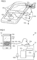
- FIG. 4 schematically illustrates a system according to various examples.
- the system 400 comprises a retrieval device 100 as described above.
- the system 400 further comprises a first device 101, and a second device 102.
- the second device can be the second device 102 described above.
- the second device can be a different mobile device, for example an authentication device built for the purpose of authentication, a tablet computer or a laptop. Many of the devices suited to act as the second device 102 are conceivable and known to the person skilled in the art.
- the second device 102 is a mobile phone.
- the first device 101 is a virtual private network gateway (VPN gateway) which comprises a connector 101a which is coupled to a security configuration entity SE 101b, an encryption/decryption unit 101c and an internal Ethernet connection 101e and an external Ethernet connection 100d.
- the first device 101 may provide a virtual access to a protected network via an external network connected at 100d for an internal network connected at 101e if a successful authentication is provided to the security configuration entity SE 101b via the connector 101a.
- VPN gateway virtual private network gateway
- the system 400 may have the advantage that the secure authentication of the first device 101 may be performed by the second device 102 and the information may be securely transferred without the need of manual input by the retrieval device 100.
- this may have the further advantage that no input means for a user, like a keyboard, is required at the VPN gateway.
- the security is increased as the attack surface is reduced, as the user has no access to the secure information used to authenticate the VPN gateway 101 to the VPN network.
- the comfort for the user may be increased, as the need to type-in the secure information is eliminated from the authentication process.
- the VPN gateway 101 may be placed in a remote location, as no direct access to the VPN gateway is required for authentication.
- the housing of the retrieval device 100 and/or the attaching means of the retrieval device 100 is adapted to cover a portion 105 of a housing of the second device 102, wherein said portion 105 of the second device 102 comprises at least one of a flash lamp and/or a light emitting diode 102b and/or a lamp and/or a screen and/or a touchscreen 102a.
- FIG. 5 is a flowchart of a method of secure authentication at a first device according to various examples.
- a second device for example the mobile phone 102 in FIG. 4 , detects that a retrieval device 100, 100a-c is connected to a light source 102.
- the light source is the touchscreen 102a of the mobile phone 102.
- the detection is enabled by the touchscreen 102a.
- the detecting 1001 comprises a determining of a contact region of the second device to which the retrieval device is connected.
- a possible contact region 104 is indicated to the user via the touchscreen. The area of this possible contact region 104 is smaller than the useable area of the touchscreen 102a, leaving an area 103 available to display instructions to the user.
- the contact region 105 is then detected according to a touchscreen signal.
- the design of the attaching means is designed according to the specifications of touchscreens to use. For example, some touchscreens can detect up to 10 touch points simultaneously. For those touchscreens, the resolution of the touchscreen and the number of touch points can be taken into consideration when designing which part of the attaching means should be made of a material that is detectable by the touchscreen upon contact. For example if the housing 100a has a box-like shape like the housing 100a shown in FIG. 1 , the four corners in contact with the screen could be made of touch-detectable material, while the edges of the housing could be made of non-touch-detectable material. In this case, the pattern of the four contact points can be recognized by a software running on the second device 102. Many other arrangements are conceivable which take into consideration at least one of the minimum size for an element to be detectable and the required spacing between two detectable elements to be separately detectable by the touchscreen.
- the second device 102 controls an emission of light encoding information, wherein the information comprises an authentication code for the first device.
- the controlling 1002 comprises an emission of light by the second device 102 in at least a part of the contact region 105.
- FIG. 6 is a flowchart of a method according to various examples.
- the method shown in FIG. 6 may be used for secure authentication at a first device, for example the VPN gateway 101 of FIG. 4 , a field device like a medical device or any other device, which requires authentication.
- a first device for example the VPN gateway 101 of FIG. 4
- a field device like a medical device or any other device, which requires authentication.
- a retrieval device is physically connected to a second device.
- the second device has light emission capabilities.
- the retrieval device may be an embodiment of the retrieval devices 100 as described above.
- the second device may be a second device 102 as described above, for example a mobile phone or any other suited device as described above.
- optical information is submitted by a light source of the second device.
- the optical information is received by a light receiver of the retrieval device.
- the light receiver is a light receiver 100c as described above.
- a signal indicative of the optical information is transferred via a connection means of the retrieval device to the first device.
- the connection means are the connection means 100d, 100e described above.
- step 1014 the user is authenticated on the first device based on the signal.
- This method may have the advantage to make the authentication process easier and faster for the user, more secure, and more reliable.
- the validity of the received authentication code may be verified on the first device using verification information stored on the first device, or by accessing a user authentication server over a communication network.
- the received authentication code is used by the first device as parameter in a cryptographic authentication and key agreement protocol, e.g. IKEv2 (Internet Key Exchange version 2), PAKE (password authenticated key agreement) or TLS AKA (transport layer security authentication and key agreement).
- the first device runs the authentication and key agreement protocol to establish a cryptographic security parameter with a peer device over a communication network (e.g., Internet, mobile communications network).
- the authentication code may be a bitstring, a numeric PIN code, a password, a JSON web token, a cryptographic key, a key generation parameter or any other type of authentication code and/or its representation, for example a bar-code, a QR code or the like.
Abstract
Description
- Various examples of the invention generally relate to secure authentication and retrieval devices for the retrieval of authentication information.
- Encryption devices are used to send and receive data communication via open networks and to secure this communication against manipulation, monitoring, and/or interception. An encryption device may protect the data communication against manipulation by using cryptographic check sums (message authentication code, digital signatures) or by using an authenticated encryption mode, protecting the integrity of sent and received data communication and ensuring the authenticity of communication peers. An encryption device may cryptographically protect only the integrity of data communication by using an integrity-only ciphersuite. It may protect the confidentiality of data communication by encrypting/decrypting the data. An encryption device may protect both the integrity and the confidentiality of data communication. Many industrial field devices require a security configuration, for example for connection to a remote entity, for example a remote network, like a virtual private network (VPN) access device. In other field devices an authentication of a user can be required, for example for service access to a medical imaging device.
- Establishment and/or activation of such a security configuration and/or authentication of a user is known to be possible by several means, for example: explicit configuration by an administration interface, loading of a configuration from a configuration memory module, loading of a configuration from a configuration server, auto-configuration (so-called "plug and work"). Furthermore, training is known from methods such as pairing, teach-in, Wi-Fi Protected Setup (WPS) from application fields such as Bluetooth and Wi-Fi connections. In such cases, the security configuration is trained for example upon a first activation of a device or upon a keypress. Training can be protected by different methods. For example, training can be only possible in a short time interval following a keypress of a device. Protection can also be provided by other technical measures. For example, a personal identification number (PIN) or password has to be entered by user or a PIN is checked by the device in another form.
- In the field of on-line banking services, so-called "flicker-codes" are known. An example for such a flicker-code based system may be found here: https://agses.net/the-agses-technology/three-basic-components/flicker-code-generator/, retrieved April 12, 2018, https://agses.net/how-agses-works-simple-and-secure/, retrieved April 12, 2018.
- In a flicker-code based authentication procedure, security code is optically modulated and displayed on a screen. Displaying on the screen can be achieved by using images on a web page, which are displayed by screen. A receiving device is then used to receive flicker code and decode it. To this end the receiving device must be held by a user against the screen displaying the flicker code at a given angle.
- Entering a PIN can be a cumbersome task, requiring at least one hand of the user. While PINs with a larger number of digits provide an elevated level of security (at least when different digits are used), the length of PINs is limited in practice, as longer PINs increase the risk of wrong input by the user and are inconvenient for a user to enter. Similar to PINs, also a password or another authentication code may be used. String passwords or authentication codes, e.g., a hexadecimal authentication code, are tedious to enter, in particular on devices without an alphanumeric keyboard.
- On the other hand, flicker codes may be recorded by an attacker by observing the screen on which they are displayed, giving a possibility for attacks. The correct detection of the flicker code by the receiving device may depend upon environmental conditions, e.g. the illumination of the screen by other light sources. Also, holding the receiving device at the required angle for detection requires the attention of the user and may be cumbersome or even impractical in some applications, for example if field devices have a screen in inconvenient location for authentication or no screen at all.
- The document
US 8,531,247 B2 , the document the documentUS 8,892,616 B2 , the documentUS 8,300,811 B2 , the documentUS 9,147,088 B2 US 9584311 B2 EP 2976707 B1 , the documentEP 2 605 445 B1 , the documentEP 2 870 565 A1 , the documentEP 2 891 102 A1 , the documentWO 2017137256 A1 , the documentEP 2870565 B1 , the documentEP 3028140 B1 , the documentEP 17175275 US 8 843 761 B2 are known from prior art. - From different field it is known to use suction cups as attaching means to detachably attach mechanical hooks, for example towel holders, to tiles, or GPS navigation systems to windshields in cars.
- Therefore, there is a need to make a required security configuration for a first device easier and faster for the user, more secure, and more reliable.
- This need is met by the features of the independent claims. Features of the dependent claims define further embodiments.
- According to an embodiment, a retrieval device for secure retrieval of optical information for a first device from a light source of a second device is provided, comprising:
A housing, made from at least one material, which is opaque for the light, emitted from the light source, wherein the housing is arranged to contain the light from at least a part of the light source. - In addition, the retrieval device comprises an attaching means adapted to detachably attach the housing to the second device.
- The retrieval device further comprises a light receiver arranged to receive optical information from the light source, said light receiver located inside the housing.
- The retrieval device further comprises a connection means, arranged to transfer an optical and/or electrical signal from the light receiver (100c) to the first device.
- According to an embodiment, a method of secure authentication at a first device is provided. The method comprises:
Detecting, by a second device, that a retrieval device is connected to a light source and controlling, by the second device, an emission of light encoding information, wherein the information comprises an authentication code for the first device. - According to an embodiment, a system is provided. The system comprises a retrieval device according to one of the embodiments described above or below, a first device and a second device.
- It is to be understood that the features mentioned above and features yet to be explained below can be used not only in the respective combinations indicated, but also in other combinations or in isolation, without departing from the scope of the present invention. Features of the above-mentioned aspects and embodiments may be combined with each other in other embodiments.
-
-
FIG. 1 schematically illustrates a retrieval device according to various examples. -
FIG. 2 andFIG. 3 schematically illustrate retrieval devices according to various examples. -
FIG. 4 schematically illustrates a system according to various examples. -
FIG. 5 is a flowchart of a method of secure authentication at a first device according to various examples. -
FIG. 6 is a flowchart of a method according to various examples - In the following, embodiments of the invention will be described in detail with reference to the accompanying drawings. It is to be understood that the following description of embodiments is not to be taken in a limiting sense. The scope of the invention is not intended to be limited by the embodiments described hereinafter or by the drawings, which are taken to be illustrative only.
- The drawings are to be regarded as being schematic representations and elements illustrated in the drawings are not necessarily shown to scale. Rather, the various elements are represented such that their function and general purpose become apparent to a person skilled in the art. Any connection or coupling between functional blocks, devices, components, or other physical or functional units shown in the drawings or described herein may also be implemented by an indirect connection or coupling. A coupling between components may also be established over a wireless connection. Functional blocks may be implemented in hardware, firmware, software, or a combination thereof.
- Generally, the techniques described herein may find application in various kinds and types of security-critical or safety-critical systems. For example, the techniques described herein may find application in the user access control for field device, for example a medical device in a hospital, like an Magnetic resonance imaging (MRI) or Computed tomography (CT) device or for a network connection node, for example VPN access unit which allows the access of the local network in a manufacturing plant in a first country to a private network in central location of the company, for example the headquarters in a second country, or an automation device.
-
FIG. 1 schematically illustrates a retrieval device according to various examples.FIG. 2 andFIG. 3 schematically illustrate retrieval devices according to various examples. - An embodiment of the
retrieval device 100a-e for secure retrieval of optical information for a first device is shown inFIG. 1 . Further embodiments of theretrieval device 100 are shown inFIG. 2 andFIG. 3 , wherein identical reference signs denote identical or functionally equivalent or related elements. - The
retrieval device 100 retrieves optical information from alight source second device 102. In the embodiment shown inFIGs. 1, 2 , and3 , thesecond device 102 is a mobile phone, which has the following controllable light sources: atouchscreen 102a, anLED 102b and a flashlight (on the backside, not shown). However, other light sources may be used. - The
second device 102 can be any kind of mobile entity used by a person for his or her personal communication, e.g. a cellular phone, a mobile station, a PDA type of device like laptop, notebook, notepad, tablet, etc. - The
retrieval device 100a-e comprises ahousing 100a, which is made from at least one material, which is opaque for the light emitted from thelight source FIG. 1 , the housing has a box-like shape and in some embodiments is made of plastic. However, many other materials, which are opaque for the light spectrum emitted from the light source, for example light in the visible range, are conceivable, for example metals, cardboard, wood, ceramics, rubber and material composites. Thehousing 100a is arranged to contain the light from at least a part of thelight source FIG. 1 , the housing has a flat shape, which allows the housing to have a light-tight fit with thescreen 102a, so that no light emitted in the region of thescreen 102a which is covered by thehousing 100a may escape. - This can have the effect that the optical information, which can be used for secure authentication, may be contained within the housing, protecting against monitoring of the light by an attacker.
- The retrieval device further comprises an attaching
means 100b adapted to detachably attach thehousing 100a to thesecond device 102. The attaching means are arranged to detachably attach to thedisplay screen 102a. In the embodiment ofFIG. 1 , the attachingmeans 100b is a rubber band, which may be wrapped around phone to securely fasten thehousing 100a in a fixed position on thedisplay 102a. Many embodiments using rubber elements in various shapes are conceivable.FIG. 2 andFIG. 3 show various other examples for attaching means; however, many other attaching means are conceivable. In the example ofFIG. 2 , amagnet 102c, aferromagnetic material 102c, or a hook andloop fastener 102c is provided by the mobile phone or by a case of the mobile phone. Theretrieval device 100 comprises attaching means. For example a ferromagnetic plate, for example made from ferromagnetic steel, to attach to themagnet 102c. Themagnet 102c can be a magnet provided at a plug of the mobile phone for a magnetic connection of a charging device. - The
retrieval device 100 itself may also comprise a magnet to attach to aferromagnetic material 102c, which is part of the mobile device or the casing of the mobile device. In further embodiments, 102c is a hook and loop fastener and the attaching means of the retrieval device comprise a matching hook and loop fastener. -
FIG. 3 shows threedifferent retrieval devices 100. InFIG. 3 , the retrieval devices are shown simultaneously attached to themobile phone 102. However, as inFIG. 1 and FIG. 2 , only one retrieval device is in use at one point in time and/or through the authentication. InFIG. 3 , various different examples of attachingmeans 100b can be seen, which includes a suction means, for example a suction cup, an elastic element which snaps onto the shape of themobile phone 102 as for example known from mobile phone covers, and a clamping element which comprises a spring element. - The attaching means may have the effect that the connection point between the
housing 100a andlight source - It is possible, that at least a part of at least one of the
housing 100a and the attachingmeans 100b is made of a flexible material. This may have the positive effect that an even tighter seal, suppressing the release of light to the outside of thehousing 100a may be achieved by deformation of the flexible material. For example, thehousing 100a inFIG. 1 may comprise a rim that acts like a gasket, for example made of rubber. This may have the further advantage to securely attach theretrieval device 100 in place, so that it does not move even as acceleration forces, for example due to vibrations, occur. It also contributes to no or only miniscule amounts of light escaping from the housing. - At least a part of the attaching means is made of a material that is detectable by a touchscreen upon contact. This may have the advantage, that the
second device 102, for example themobile phone 102, can detect the presence of the retrieval device. The detection of the presence of the retrieval device may be used to control the authentication as will be explained further below. - The retrieval device further comprises a
light receiver 100c. The light receiver is arranged to receive optical information from thelight source - The
light receiver 100c is located inside thehousing 100a, so that the optical information may be received by thelight receiver 100c while no light is released to the surrounding environment. - The retrieval device further comprises a connection means (100d, 100e) arranged to transfer an optical and/or electrical signal from the light receiver (100c) to the first device (101) .
- The connection means 100d, 100e comprise an
optical fiber 100d comprising a first end and a second end, where the first end is the light receiver and thesecond end 100e is adapted to be coupled to the first device. The second end comprises a connector for theoptical fiber 100e, for example a SubMiniature Assembly SMA905 connector, or a different connector. - In case an electronic signal is transferred, 100d may comprise electrically conducting wires and 100e may be any type of connector, including a custom-made connector. The connection means may also comprise a combination of optical and electronic components, for example wires to provide electrical power for a detection circuit placed inside the
housing 100a, as well as an optical fiber to transfer an optical signal from the detection circuit. -
FIG. 4 schematically illustrates a system according to various examples. - The
system 400 comprises aretrieval device 100 as described above. Thesystem 400 further comprises afirst device 101, and asecond device 102. - The second device can be the
second device 102 described above. The second device can be a different mobile device, for example an authentication device built for the purpose of authentication, a tablet computer or a laptop. Many of the devices suited to act as thesecond device 102 are conceivable and known to the person skilled in the art. - In the example of
FIG. 4 , thesecond device 102 is a mobile phone. - The example of
FIG. 4 , thefirst device 101 is a virtual private network gateway (VPN gateway) which comprises aconnector 101a which is coupled to a securityconfiguration entity SE 101b, an encryption/decryption unit 101c and aninternal Ethernet connection 101e and anexternal Ethernet connection 100d. Thefirst device 101 may provide a virtual access to a protected network via an external network connected at 100d for an internal network connected at 101e if a successful authentication is provided to the securityconfiguration entity SE 101b via theconnector 101a. - The
system 400 may have the advantage that the secure authentication of thefirst device 101 may be performed by thesecond device 102 and the information may be securely transferred without the need of manual input by theretrieval device 100. In the example shown inFIG. 4 this may have the further advantage that no input means for a user, like a keyboard, is required at the VPN gateway. In addition, the security is increased as the attack surface is reduced, as the user has no access to the secure information used to authenticate theVPN gateway 101 to the VPN network. In addition, the comfort for the user may be increased, as the need to type-in the secure information is eliminated from the authentication process. In addition, theVPN gateway 101 may be placed in a remote location, as no direct access to the VPN gateway is required for authentication. - In the
system 400 the housing of theretrieval device 100 and/or the attaching means of theretrieval device 100 is adapted to cover aportion 105 of a housing of thesecond device 102, wherein saidportion 105 of thesecond device 102 comprises at least one of a flash lamp and/or alight emitting diode 102b and/or a lamp and/or a screen and/or atouchscreen 102a. -
FIG. 5 is a flowchart of a method of secure authentication at a first device according to various examples. - The method comprises the following steps:
At step 1001 a second device, for example themobile phone 102 inFIG. 4 , detects that aretrieval device light source 102. In the example ofFIG. 4 , the light source is thetouchscreen 102a of themobile phone 102. In the example ofFIG. 4 , the detection is enabled by thetouchscreen 102a. The detecting 1001 comprises a determining of a contact region of the second device to which the retrieval device is connected. In the example ofFIG. 4 , apossible contact region 104 is indicated to the user via the touchscreen. The area of thispossible contact region 104 is smaller than the useable area of thetouchscreen 102a, leaving anarea 103 available to display instructions to the user. Thecontact region 105 is then detected according to a touchscreen signal. The design of the attaching means is designed according to the specifications of touchscreens to use. For example, some touchscreens can detect up to 10 touch points simultaneously. For those touchscreens, the resolution of the touchscreen and the number of touch points can be taken into consideration when designing which part of the attaching means should be made of a material that is detectable by the touchscreen upon contact. For example if thehousing 100a has a box-like shape like thehousing 100a shown inFIG. 1 , the four corners in contact with the screen could be made of touch-detectable material, while the edges of the housing could be made of non-touch-detectable material. In this case, the pattern of the four contact points can be recognized by a software running on thesecond device 102. Many other arrangements are conceivable which take into consideration at least one of the minimum size for an element to be detectable and the required spacing between two detectable elements to be separately detectable by the touchscreen. - In
step 1002, thesecond device 102 controls an emission of light encoding information, wherein the information comprises an authentication code for the first device. - The controlling 1002 comprises an emission of light by the
second device 102 in at least a part of thecontact region 105. - This may have the advantage that the second device only emits light encoding information when the
retrieval device 100 is securely attached. This can have the benefit that the security configuration is easier, as no manual entry of a password or a PIN is required. It can also make the configuration faster for the user, as the time required is no longer limited by the typing speed of the user at an interface. In addition, it can make the authentication more secure, as more complex authentication information, for example longer PIN codes, may be used. In addition, the user does not learn the PIN, thereby eliminating the risk that it is written down or memorized by the user or by an observer. It can also make the authentication more reliable, as typing mistakes by the user can be eliminated. -
FIG. 6 is a flowchart of a method according to various examples. - The method shown in
FIG. 6 may be used for secure authentication at a first device, for example theVPN gateway 101 ofFIG. 4 , a field device like a medical device or any other device, which requires authentication. - The method comprises the following steps:
Atstep 1010, a retrieval device is physically connected to a second device. The second device has light emission capabilities. The retrieval device may be an embodiment of theretrieval devices 100 as described above. The second device may be asecond device 102 as described above, for example a mobile phone or any other suited device as described above. - At
step 1011, optical information is submitted by a light source of the second device. - At
step 1012, the optical information is received by a light receiver of the retrieval device. The light receiver is alight receiver 100c as described above. - At
step 1013, a signal indicative of the optical information is transferred via a connection means of the retrieval device to the first device. The connection means are the connection means 100d, 100e described above. - In
step 1014, the user is authenticated on the first device based on the signal. - This method may have the advantage to make the authentication process easier and faster for the user, more secure, and more reliable.
- The validity of the received authentication code may be verified on the first device using verification information stored on the first device, or by accessing a user authentication server over a communication network. In another embodiment (not shown), the received authentication code is used by the first device as parameter in a cryptographic authentication and key agreement protocol, e.g. IKEv2 (Internet Key Exchange version 2), PAKE (password authenticated key agreement) or TLS AKA (transport layer security authentication and key agreement). In some examples, the first device runs the authentication and key agreement protocol to establish a cryptographic security parameter with a peer device over a communication network (e.g., Internet, mobile communications network). The authentication code may be a bitstring, a numeric PIN code, a password, a JSON web token, a cryptographic key, a key generation parameter or any other type of authentication code and/or its representation, for example a bar-code, a QR code or the like.
Claims (15)
- A retrieval device (100) for secure retrieval of optical information for a first device (101) from a light source (102a, 102b) of a second device (102), the second device providing the optical information by the light source (102a, 102b), the device comprising:- a housing (100a) made from at least one material which is opaque for the light emitted from the light source (102a, 102b), wherein the housing (100a) is arranged to contain the light from at least a part of the light source (102a, 102b),- an attaching means (100b) arranged to detachably attach the housing (100a) to the second device (102),- a light receiver (100c) arranged to receive the optical information from the light source (102a,
102b), said light receiver (100c) located inside the housing (100a),- a connection means (100d, 100e) arranged to transfer an optical and/or electrical signal from the light receiver (100c) to the first device (101). - The retrieval device (100) of claim 1, in which the attaching means (100b) comprises at least one of
a suction means, a magnet, a hook-and-loop fastener, an elastic element, a rubber band, a rubber element a spring element, a clamping element. - The retrieval device (100) of one of the above claims, in which at least a part of at least one of the housing (100a) and the attaching means (100b) is made of a flexible material.
- The retrieval device (100) of one of the above claims, in which at least a part of the attaching means is made of a material that is detectable by a touchscreen upon contact.
- The retrieval device (100) of one of the above claims, in which the connection means comprise an optical fiber comprising a first end and a second end, where the first end is the light receiver and the second end is adapted to be coupled to the first device.
- The retrieval device (100) of one of the above claims, in which the connection means comprises an electrical connection and the light receiver comprises at least one light sensor.
- The retrieval device (100) of one of the above claims, in which the attaching means are arranged to detachably attach to a display screen.
- A method of secure authentication at a first device, comprising:- detecting (1001), by a second device (102), that a retrieval device (100) is connected to a light source,- controlling (1002), by the second device (102), an emission of light encoding information, wherein the information comprises an authentication code for the first device.
- A method according to claim 8, in which- the detecting (1001) comprises a determining of a contact region of the second device to which the retrieval device is connected and- wherein the controlling (1002) comprises an emission of light by the second device in at least a part of the contact region.
- A method for secure authentication at a first device comprising:- physically connecting (1010) a retrieval device according to one of the above claims 1-10 to a second device, wherein the second device has light emission capabilities,- emitting (1011) optical information by a light source of the second device,- receiving (1012) of the optical information by a light receiver of the retrieval device,- transferring (1013) a signal indicative of the optical information via a connection means of the retrieval device to the first device,- authenticating (1014) the user on the first device based on the signal.
- The method of claim 10, in which the optical information is a flicker code.
- A system, comprising:- a retrieval device (100) according to any one of claims 1-7,- a first device (101),- a second device (102).
- The system of claim 12, in which the second device (102) is a mobile device and/or a mobile phone and/or a tablet and/or a laptop, and/or in which the first device (101) is a virtual private network gateway and/or a field device.
- The system of claims 12 or 13, in which the housing of the retrieval device (100) and/or the attaching means of the retrieval device (100) is adapted to cover a portion (105) of a housing of the second device (102), wherein said portion (105) of the second device (102) comprises at least one of a flash lamp and/or a light emitting diode (102b) and/or a lamp and/or a screen and/or a touchscreen (102a).
- The system of any one of claims 12 - 13,
wherein the first device (101) further comprises:- a further connection means (101a) adapted to connect to the connection means (100e) of the retrieval device (100),- a decoding means (101b) to receive information transmitted by the optical and/or electrical signal from the retrieval device,- an authentication means (101c) to allow access to said device in reaction to the information.
Priority Applications (3)
| Application Number | Priority Date | Filing Date | Title |
|---|---|---|---|
| EP18169254.2A EP3561713B1 (en) | 2018-04-25 | 2018-04-25 | Retrieval device for authentication information, system and method for secure authentication |
| US16/388,417 US10715517B2 (en) | 2018-04-25 | 2019-04-18 | Retrieval device for authentication information, system and method for secure authentication |
| CN201910338361.XA CN110401495B (en) | 2018-04-25 | 2019-04-25 | Retrieval device, system for authentication information and method for security authentication |
Applications Claiming Priority (1)
| Application Number | Priority Date | Filing Date | Title |
|---|---|---|---|
| EP18169254.2A EP3561713B1 (en) | 2018-04-25 | 2018-04-25 | Retrieval device for authentication information, system and method for secure authentication |
Publications (2)
| Publication Number | Publication Date |
|---|---|
| EP3561713A1 true EP3561713A1 (en) | 2019-10-30 |
| EP3561713B1 EP3561713B1 (en) | 2022-07-13 |
Family
ID=62196299
Family Applications (1)
| Application Number | Title | Priority Date | Filing Date |
|---|---|---|---|
| EP18169254.2A Active EP3561713B1 (en) | 2018-04-25 | 2018-04-25 | Retrieval device for authentication information, system and method for secure authentication |
Country Status (3)
| Country | Link |
|---|---|
| US (1) | US10715517B2 (en) |
| EP (1) | EP3561713B1 (en) |
| CN (1) | CN110401495B (en) |
Cited By (1)
| Publication number | Priority date | Publication date | Assignee | Title |
|---|---|---|---|---|
| US11882447B2 (en) | 2018-08-09 | 2024-01-23 | Siemens Aktiengesellschaft | Computer-implemented method and network access server for connecting a network component to a network with an extended network access identifier |
Citations (17)
| Publication number | Priority date | Publication date | Assignee | Title |
|---|---|---|---|---|
| EP0175275A2 (en) | 1984-09-12 | 1986-03-26 | Matsushita Electric Industrial Co., Ltd. | Non-linear signal processing apparatus |
| EP2239919A1 (en) * | 2009-04-08 | 2010-10-13 | Research In Motion Limited | Systems, devices and methods for securely transmitting a security parameter to a computing device |
| EP2493230A1 (en) * | 2011-02-23 | 2012-08-29 | Samsung Electronics Co., Ltd. | Method for authenticating mobile device and display apparatus using the same, and mobile device authentication system |
| US8300811B2 (en) | 2008-12-10 | 2012-10-30 | Siemens Aktiengesellschaft | Method and device for processing data |
| US8531247B2 (en) | 2008-04-14 | 2013-09-10 | Siemens Aktiengesellschaft | Device and method for generating a random bit sequence |
| US20140122884A1 (en) * | 2012-10-25 | 2014-05-01 | International Business Machines Corporation | Decoupled cryptographic schemes using a visual channel |
| US8843761B2 (en) | 2007-08-16 | 2014-09-23 | Siemens Aktiengesellschaft | Method and apparatus for protection of a program against monitoring flow manipulation and against incorrect program running |
| US8892616B2 (en) | 2007-08-27 | 2014-11-18 | Siemens Aktiengesellschaft | Device and method for generating a random bit sequence |
| US20150071438A1 (en) * | 2013-09-10 | 2015-03-12 | Marvell World Trade Ltd. | Secure device bootstrap identity |
| EP2870565A1 (en) | 2012-09-28 | 2015-05-13 | Siemens Aktiengesellschaft | Testing integrity of property data of a device using a testing device |
| EP2891102A1 (en) | 2013-01-02 | 2015-07-08 | Siemens Aktiengesellschaft | Rfid tag and method for operating an rfid tag |
| US9147088B2 (en) | 2011-04-18 | 2015-09-29 | Siemens Aktiengesellschaft | Method for monitoring a tamper protection and monitoring system for a field device having tamper protection |
| EP2605445B1 (en) | 2011-12-14 | 2015-09-30 | Siemens Aktiengesellschaft | Method and apparatus for securing block ciphers against template attacks |
| EP2976707B1 (en) | 2013-05-03 | 2017-02-01 | Siemens Aktiengesellschaft | System and method for generating random bits |
| US9584311B2 (en) | 2011-12-06 | 2017-02-28 | Siemens Aktiengesellschaft | Decrypting data |
| EP3028140B1 (en) | 2013-10-31 | 2017-08-02 | Siemens Aktiengesellschaft | Design of a circuit suitable for generating random bits and circuit for generating random bits |
| WO2017137256A1 (en) | 2016-02-09 | 2017-08-17 | Siemens Aktiengesellschaft | Method and execution environment for the secure execution of program instructions |
Family Cites Families (29)
| Publication number | Priority date | Publication date | Assignee | Title |
|---|---|---|---|---|
| US6450677B1 (en) * | 2000-09-21 | 2002-09-17 | Robert M. Knauer | Fiberoptic lighting system |
| US7224910B2 (en) * | 2002-10-25 | 2007-05-29 | Gennum Corporation | Direct attach optical receiver module and method of testing |
| EP1678940A1 (en) * | 2003-10-21 | 2006-07-12 | Koninklijke Philips Electronics N.V. | Screen image authentication |
| CA2606052A1 (en) * | 2005-04-25 | 2006-11-02 | Mobiqa Limited | Mobile ticket authentication |
| CN101652782B (en) * | 2007-04-05 | 2014-04-02 | 英特尔移动通信有限责任公司 | Communication terminal device, communication device, electronic card, method for a communication terminal device and method for a communication device for providing a verification |
| US11978079B2 (en) * | 2008-09-04 | 2024-05-07 | Tara Chand Singhal | Systems and methods for an electronic coupon system |
| DE102009012518A1 (en) * | 2009-03-10 | 2010-09-16 | Fujitsu Siemens Computers Gmbh | Transmission unit for transmitting data in an optical data network and method for aligning such a transmission unit |
| DE102010033230A1 (en) * | 2010-08-03 | 2012-02-09 | Siemens Aktiengesellschaft | Method and device for integrating a device in a network |
| CA2817823C (en) * | 2011-06-22 | 2019-05-07 | International Business Machines Corporation | Mobile touch-generating device and communication with a touchscreen |
| US9277401B2 (en) * | 2013-01-22 | 2016-03-01 | Qualcomm Incorporated | Device utilizing an optical signal to access an access point |
| DE102013201027A1 (en) * | 2013-01-23 | 2014-07-24 | Bundesdruckerei Gmbh | Method for authenticating a user to a vending machine |
| DE102013002231A1 (en) * | 2013-02-11 | 2014-08-14 | Fresenius Medical Care Deutschland Gmbh | Apparatus and method for generating and displaying graphics encodings specific to medical devices and medical treatments |
| US10841289B2 (en) * | 2013-03-18 | 2020-11-17 | Digimarc Corporation | Mobile devices as security tokens |
| WO2015039037A2 (en) * | 2013-09-13 | 2015-03-19 | Cooper Technologies Company | Artificial light source based messaging platform |
| EP3049838A4 (en) * | 2013-09-24 | 2017-07-26 | CommScope Technologies LLC | Pluggable active optical module with managed connectivity support and simulated memory table |
| GB201321262D0 (en) * | 2013-12-02 | 2014-01-15 | Univ Edinburgh | Receiver for communications stytems |
| US9179493B1 (en) * | 2014-04-17 | 2015-11-03 | Huntingdon Telemed, LLC | Medical cart system |
| US9843385B2 (en) * | 2014-06-13 | 2017-12-12 | Verily Life Sciences Llc | Optical communication for body mountable devices |
| US20160087726A1 (en) * | 2014-09-19 | 2016-03-24 | L3 Communications Corporation | Free space fiber-optic connector |
| DE102014220808B4 (en) * | 2014-10-14 | 2016-05-19 | Siemens Aktiengesellschaft | Method and device for logging in medical devices |
| US9853730B2 (en) * | 2015-02-27 | 2017-12-26 | Xicato, Inc. | Lighting based authentication of a mobile electronic device |
| US9564027B2 (en) * | 2015-03-24 | 2017-02-07 | Lenovo Enterprise Solutions (Singapore) Pte. Ltd. | Modulating brightness of optical element conveying human-discernible information to also convey machine-discernible information |
| KR102043091B1 (en) * | 2015-03-25 | 2019-12-02 | 쿠앙치 인텔리전트 포토닉 테크놀로지 리미티드 | Optical signal receiver |
| JP2016224535A (en) * | 2015-05-27 | 2016-12-28 | ミネベア株式会社 | Authentication system, authentication method, server device, and client device |
| US9941965B2 (en) * | 2015-07-15 | 2018-04-10 | Flextronics Ap, Llc | Laser and optical charging and communications device and method of use |
| US20170048953A1 (en) * | 2015-08-11 | 2017-02-16 | Federal Law Enforcement Development Services, Inc. | Programmable switch and system |
| US9847020B2 (en) * | 2015-10-10 | 2017-12-19 | Videx, Inc. | Visible light communication of an access credential in an access control system |
| US10270528B1 (en) * | 2016-06-30 | 2019-04-23 | Google Llc | Serial communication to device through lighting control |
| CN107291224B (en) * | 2017-06-07 | 2021-01-29 | 驭势(上海)汽车科技有限公司 | Equipment control method and equipment control device |
-
2018
- 2018-04-25 EP EP18169254.2A patent/EP3561713B1/en active Active
-
2019
- 2019-04-18 US US16/388,417 patent/US10715517B2/en active Active
- 2019-04-25 CN CN201910338361.XA patent/CN110401495B/en not_active Expired - Fee Related
Patent Citations (18)
| Publication number | Priority date | Publication date | Assignee | Title |
|---|---|---|---|---|
| EP0175275A2 (en) | 1984-09-12 | 1986-03-26 | Matsushita Electric Industrial Co., Ltd. | Non-linear signal processing apparatus |
| US8843761B2 (en) | 2007-08-16 | 2014-09-23 | Siemens Aktiengesellschaft | Method and apparatus for protection of a program against monitoring flow manipulation and against incorrect program running |
| US8892616B2 (en) | 2007-08-27 | 2014-11-18 | Siemens Aktiengesellschaft | Device and method for generating a random bit sequence |
| US8531247B2 (en) | 2008-04-14 | 2013-09-10 | Siemens Aktiengesellschaft | Device and method for generating a random bit sequence |
| US8300811B2 (en) | 2008-12-10 | 2012-10-30 | Siemens Aktiengesellschaft | Method and device for processing data |
| EP2239919A1 (en) * | 2009-04-08 | 2010-10-13 | Research In Motion Limited | Systems, devices and methods for securely transmitting a security parameter to a computing device |
| EP2493230A1 (en) * | 2011-02-23 | 2012-08-29 | Samsung Electronics Co., Ltd. | Method for authenticating mobile device and display apparatus using the same, and mobile device authentication system |
| US9147088B2 (en) | 2011-04-18 | 2015-09-29 | Siemens Aktiengesellschaft | Method for monitoring a tamper protection and monitoring system for a field device having tamper protection |
| US9584311B2 (en) | 2011-12-06 | 2017-02-28 | Siemens Aktiengesellschaft | Decrypting data |
| EP2605445B1 (en) | 2011-12-14 | 2015-09-30 | Siemens Aktiengesellschaft | Method and apparatus for securing block ciphers against template attacks |
| EP2870565A1 (en) | 2012-09-28 | 2015-05-13 | Siemens Aktiengesellschaft | Testing integrity of property data of a device using a testing device |
| EP2870565B1 (en) | 2012-09-28 | 2017-09-27 | Siemens Aktiengesellschaft | Testing integrity of property data of a device using a testing device |
| US20140122884A1 (en) * | 2012-10-25 | 2014-05-01 | International Business Machines Corporation | Decoupled cryptographic schemes using a visual channel |
| EP2891102A1 (en) | 2013-01-02 | 2015-07-08 | Siemens Aktiengesellschaft | Rfid tag and method for operating an rfid tag |
| EP2976707B1 (en) | 2013-05-03 | 2017-02-01 | Siemens Aktiengesellschaft | System and method for generating random bits |
| US20150071438A1 (en) * | 2013-09-10 | 2015-03-12 | Marvell World Trade Ltd. | Secure device bootstrap identity |
| EP3028140B1 (en) | 2013-10-31 | 2017-08-02 | Siemens Aktiengesellschaft | Design of a circuit suitable for generating random bits and circuit for generating random bits |
| WO2017137256A1 (en) | 2016-02-09 | 2017-08-17 | Siemens Aktiengesellschaft | Method and execution environment for the secure execution of program instructions |
Cited By (1)
| Publication number | Priority date | Publication date | Assignee | Title |
|---|---|---|---|---|
| US11882447B2 (en) | 2018-08-09 | 2024-01-23 | Siemens Aktiengesellschaft | Computer-implemented method and network access server for connecting a network component to a network with an extended network access identifier |
Also Published As
| Publication number | Publication date |
|---|---|
| CN110401495B (en) | 2022-11-22 |
| CN110401495A (en) | 2019-11-01 |
| US20190334891A1 (en) | 2019-10-31 |
| EP3561713B1 (en) | 2022-07-13 |
| US10715517B2 (en) | 2020-07-14 |
Similar Documents
| Publication | Publication Date | Title |
|---|---|---|
| US9954871B2 (en) | Method and system to protect software-based network-connected devices from advanced persistent threat | |
| US11665524B2 (en) | Apparatus and method for registering and associating internet of things (IoT) devices with anonymous IoT device accounts | |
| CN105392134B (en) | The method of at least one first unit is authenticated at least one second unit | |
| Filkins et al. | Privacy and security in the era of digital health: what should translational researchers know and do about it? | |
| US11494754B2 (en) | Methods for locating an antenna within an electronic device | |
| AU2014258980B2 (en) | Providing digital certificates | |
| WO2017106222A1 (en) | Internet of things (iot) apparatus and method for coin operated devices | |
| US10856146B2 (en) | Electronic device verification | |
| US11694149B2 (en) | Apparatus and method for secure transport using internet of things (IoT) devices | |
| US20190182049A1 (en) | System and method for tamper-resistant device usage metering | |
| WO2020116975A1 (en) | Access security system using security card and mobile terminal, and security method for same | |
| US11284257B2 (en) | Validation engine | |
| US20210152359A1 (en) | Authentication device based on biometric information, control server and application server, and operation method thereof | |
| US10715517B2 (en) | Retrieval device for authentication information, system and method for secure authentication | |
| CN107835162B (en) | Software digital permit server gives the method and software digital permit server that permission is signed and issued in the license of software developer's software digital | |
| WO2016064040A1 (en) | User terminal using signature information to detect whether application program has been tampered and method for tamper detection using the user terminal | |
| US20210345106A1 (en) | Communication control device and communication control system | |
| JP2020123786A (en) | Communication control unit | |
| Jansen et al. | Smart Cards and Mobile Device Authentication: An Overview and Implementation | |
| ES2954418T3 (en) | Network access management method of a device and device | |
| WO2024086858A1 (en) | Ledger environment threat detection protocol system and method | |
| WO2023224749A1 (en) | Touchless identity card emulator systems and methods | |
| WO2023224766A1 (en) | System and method for machine learning (ml)-based iot device provisioning | |
| Evaldsson et al. | Evaluate Techniques For Wireless Communication From a Network Device To a Smartphone | |
| WO2019028493A1 (en) | Method, system and computer readable medium for user authentication |
Legal Events
| Date | Code | Title | Description |
|---|---|---|---|
| PUAI | Public reference made under article 153(3) epc to a published international application that has entered the european phase |
Free format text: ORIGINAL CODE: 0009012 |
|
| STAA | Information on the status of an ep patent application or granted ep patent |
Free format text: STATUS: THE APPLICATION HAS BEEN PUBLISHED |
|
| AK | Designated contracting states |
Kind code of ref document: A1 Designated state(s): AL AT BE BG CH CY CZ DE DK EE ES FI FR GB GR HR HU IE IS IT LI LT LU LV MC MK MT NL NO PL PT RO RS SE SI SK SM TR |
|
| AX | Request for extension of the european patent |
Extension state: BA ME |
|
| STAA | Information on the status of an ep patent application or granted ep patent |
Free format text: STATUS: REQUEST FOR EXAMINATION WAS MADE |
|
| 17P | Request for examination filed |
Effective date: 20200429 |
|
| RBV | Designated contracting states (corrected) |
Designated state(s): AL AT BE BG CH CY CZ DE DK EE ES FI FR GB GR HR HU IE IS IT LI LT LU LV MC MK MT NL NO PL PT RO RS SE SI SK SM TR |
|
| STAA | Information on the status of an ep patent application or granted ep patent |
Free format text: STATUS: EXAMINATION IS IN PROGRESS |
|
| STAA | Information on the status of an ep patent application or granted ep patent |
Free format text: STATUS: EXAMINATION IS IN PROGRESS |
|
| 17Q | First examination report despatched |
Effective date: 20201207 |
|
| STAA | Information on the status of an ep patent application or granted ep patent |
Free format text: STATUS: EXAMINATION IS IN PROGRESS |
|
| REG | Reference to a national code |
Ref country code: DE Ref legal event code: R079 Ref document number: 602018037816 Country of ref document: DE Free format text: PREVIOUS MAIN CLASS: G06F0021720000 Ipc: G06F0021830000 |
|
| GRAP | Despatch of communication of intention to grant a patent |
Free format text: ORIGINAL CODE: EPIDOSNIGR1 |
|
| STAA | Information on the status of an ep patent application or granted ep patent |
Free format text: STATUS: GRANT OF PATENT IS INTENDED |
|
| RIC1 | Information provided on ipc code assigned before grant |
Ipc: G06F 21/86 20130101ALI20220208BHEP Ipc: G06F 21/84 20130101ALI20220208BHEP Ipc: G06F 21/83 20130101AFI20220208BHEP |
|
| RIN1 | Information on inventor provided before grant (corrected) |
Inventor name: ZWANZGER, JOHANNES DR. Inventor name: TRUMMER, GEORG Inventor name: SPERL, FRANZ Inventor name: PFAU, AXEL Inventor name: KLASEN, WOLFGANG DR. Inventor name: HEINTEL, MARKUS Inventor name: FRIES, STEFFEN Inventor name: FALK, RAINER DR. Inventor name: ASCHAUER, HANS DR. |
|
| INTG | Intention to grant announced |
Effective date: 20220301 |
|
| GRAS | Grant fee paid |
Free format text: ORIGINAL CODE: EPIDOSNIGR3 |
|
| GRAA | (expected) grant |
Free format text: ORIGINAL CODE: 0009210 |
|
| STAA | Information on the status of an ep patent application or granted ep patent |
Free format text: STATUS: THE PATENT HAS BEEN GRANTED |
|
| AK | Designated contracting states |
Kind code of ref document: B1 Designated state(s): AL AT BE BG CH CY CZ DE DK EE ES FI FR GB GR HR HU IE IS IT LI LT LU LV MC MK MT NL NO PL PT RO RS SE SI SK SM TR |
|
| REG | Reference to a national code |
Ref country code: CH Ref legal event code: EP |
|
| REG | Reference to a national code |
Ref country code: DE Ref legal event code: R096 Ref document number: 602018037816 Country of ref document: DE |
|
| REG | Reference to a national code |
Ref country code: AT Ref legal event code: REF Ref document number: 1504643 Country of ref document: AT Kind code of ref document: T Effective date: 20220815 |
|
| REG | Reference to a national code |
Ref country code: IE Ref legal event code: FG4D |
|
| REG | Reference to a national code |
Ref country code: LT Ref legal event code: MG9D |
|
| REG | Reference to a national code |
Ref country code: NL Ref legal event code: MP Effective date: 20220713 |
|
| PG25 | Lapsed in a contracting state [announced via postgrant information from national office to epo] |
Ref country code: SE Free format text: LAPSE BECAUSE OF FAILURE TO SUBMIT A TRANSLATION OF THE DESCRIPTION OR TO PAY THE FEE WITHIN THE PRESCRIBED TIME-LIMIT Effective date: 20220713 Ref country code: RS Free format text: LAPSE BECAUSE OF FAILURE TO SUBMIT A TRANSLATION OF THE DESCRIPTION OR TO PAY THE FEE WITHIN THE PRESCRIBED TIME-LIMIT Effective date: 20220713 Ref country code: PT Free format text: LAPSE BECAUSE OF FAILURE TO SUBMIT A TRANSLATION OF THE DESCRIPTION OR TO PAY THE FEE WITHIN THE PRESCRIBED TIME-LIMIT Effective date: 20221114 Ref country code: NO Free format text: LAPSE BECAUSE OF FAILURE TO SUBMIT A TRANSLATION OF THE DESCRIPTION OR TO PAY THE FEE WITHIN THE PRESCRIBED TIME-LIMIT Effective date: 20221013 Ref country code: NL Free format text: LAPSE BECAUSE OF FAILURE TO SUBMIT A TRANSLATION OF THE DESCRIPTION OR TO PAY THE FEE WITHIN THE PRESCRIBED TIME-LIMIT Effective date: 20220713 Ref country code: LV Free format text: LAPSE BECAUSE OF FAILURE TO SUBMIT A TRANSLATION OF THE DESCRIPTION OR TO PAY THE FEE WITHIN THE PRESCRIBED TIME-LIMIT Effective date: 20220713 Ref country code: LT Free format text: LAPSE BECAUSE OF FAILURE TO SUBMIT A TRANSLATION OF THE DESCRIPTION OR TO PAY THE FEE WITHIN THE PRESCRIBED TIME-LIMIT Effective date: 20220713 Ref country code: FI Free format text: LAPSE BECAUSE OF FAILURE TO SUBMIT A TRANSLATION OF THE DESCRIPTION OR TO PAY THE FEE WITHIN THE PRESCRIBED TIME-LIMIT Effective date: 20220713 Ref country code: ES Free format text: LAPSE BECAUSE OF FAILURE TO SUBMIT A TRANSLATION OF THE DESCRIPTION OR TO PAY THE FEE WITHIN THE PRESCRIBED TIME-LIMIT Effective date: 20220713 |
|
| REG | Reference to a national code |
Ref country code: AT Ref legal event code: MK05 Ref document number: 1504643 Country of ref document: AT Kind code of ref document: T Effective date: 20220713 |
|
| PG25 | Lapsed in a contracting state [announced via postgrant information from national office to epo] |
Ref country code: PL Free format text: LAPSE BECAUSE OF FAILURE TO SUBMIT A TRANSLATION OF THE DESCRIPTION OR TO PAY THE FEE WITHIN THE PRESCRIBED TIME-LIMIT Effective date: 20220713 Ref country code: IS Free format text: LAPSE BECAUSE OF FAILURE TO SUBMIT A TRANSLATION OF THE DESCRIPTION OR TO PAY THE FEE WITHIN THE PRESCRIBED TIME-LIMIT Effective date: 20221113 Ref country code: HR Free format text: LAPSE BECAUSE OF FAILURE TO SUBMIT A TRANSLATION OF THE DESCRIPTION OR TO PAY THE FEE WITHIN THE PRESCRIBED TIME-LIMIT Effective date: 20220713 Ref country code: GR Free format text: LAPSE BECAUSE OF FAILURE TO SUBMIT A TRANSLATION OF THE DESCRIPTION OR TO PAY THE FEE WITHIN THE PRESCRIBED TIME-LIMIT Effective date: 20221014 |
|
| REG | Reference to a national code |
Ref country code: DE Ref legal event code: R097 Ref document number: 602018037816 Country of ref document: DE |
|
| PG25 | Lapsed in a contracting state [announced via postgrant information from national office to epo] |
Ref country code: SM Free format text: LAPSE BECAUSE OF FAILURE TO SUBMIT A TRANSLATION OF THE DESCRIPTION OR TO PAY THE FEE WITHIN THE PRESCRIBED TIME-LIMIT Effective date: 20220713 Ref country code: RO Free format text: LAPSE BECAUSE OF FAILURE TO SUBMIT A TRANSLATION OF THE DESCRIPTION OR TO PAY THE FEE WITHIN THE PRESCRIBED TIME-LIMIT Effective date: 20220713 Ref country code: DK Free format text: LAPSE BECAUSE OF FAILURE TO SUBMIT A TRANSLATION OF THE DESCRIPTION OR TO PAY THE FEE WITHIN THE PRESCRIBED TIME-LIMIT Effective date: 20220713 Ref country code: CZ Free format text: LAPSE BECAUSE OF FAILURE TO SUBMIT A TRANSLATION OF THE DESCRIPTION OR TO PAY THE FEE WITHIN THE PRESCRIBED TIME-LIMIT Effective date: 20220713 Ref country code: AT Free format text: LAPSE BECAUSE OF FAILURE TO SUBMIT A TRANSLATION OF THE DESCRIPTION OR TO PAY THE FEE WITHIN THE PRESCRIBED TIME-LIMIT Effective date: 20220713 |
|
| PLBE | No opposition filed within time limit |
Free format text: ORIGINAL CODE: 0009261 |
|
| STAA | Information on the status of an ep patent application or granted ep patent |
Free format text: STATUS: NO OPPOSITION FILED WITHIN TIME LIMIT |
|
| PG25 | Lapsed in a contracting state [announced via postgrant information from national office to epo] |
Ref country code: SK Free format text: LAPSE BECAUSE OF FAILURE TO SUBMIT A TRANSLATION OF THE DESCRIPTION OR TO PAY THE FEE WITHIN THE PRESCRIBED TIME-LIMIT Effective date: 20220713 Ref country code: EE Free format text: LAPSE BECAUSE OF FAILURE TO SUBMIT A TRANSLATION OF THE DESCRIPTION OR TO PAY THE FEE WITHIN THE PRESCRIBED TIME-LIMIT Effective date: 20220713 |
|
| 26N | No opposition filed |
Effective date: 20230414 |
|
| PG25 | Lapsed in a contracting state [announced via postgrant information from national office to epo] |
Ref country code: AL Free format text: LAPSE BECAUSE OF FAILURE TO SUBMIT A TRANSLATION OF THE DESCRIPTION OR TO PAY THE FEE WITHIN THE PRESCRIBED TIME-LIMIT Effective date: 20220713 |
|
| PG25 | Lapsed in a contracting state [announced via postgrant information from national office to epo] |
Ref country code: SI Free format text: LAPSE BECAUSE OF FAILURE TO SUBMIT A TRANSLATION OF THE DESCRIPTION OR TO PAY THE FEE WITHIN THE PRESCRIBED TIME-LIMIT Effective date: 20220713 |
|
| REG | Reference to a national code |
Ref country code: DE Ref legal event code: R119 Ref document number: 602018037816 Country of ref document: DE |
|
| REG | Reference to a national code |
Ref country code: CH Ref legal event code: PL |
|
| GBPC | Gb: european patent ceased through non-payment of renewal fee |
Effective date: 20230425 |
|
| PG25 | Lapsed in a contracting state [announced via postgrant information from national office to epo] |
Ref country code: LU Free format text: LAPSE BECAUSE OF NON-PAYMENT OF DUE FEES Effective date: 20230425 |
|
| REG | Reference to a national code |
Ref country code: BE Ref legal event code: MM Effective date: 20230430 |
|
| PG25 | Lapsed in a contracting state [announced via postgrant information from national office to epo] |
Ref country code: MC Free format text: LAPSE BECAUSE OF FAILURE TO SUBMIT A TRANSLATION OF THE DESCRIPTION OR TO PAY THE FEE WITHIN THE PRESCRIBED TIME-LIMIT Effective date: 20220713 |
|
| PG25 | Lapsed in a contracting state [announced via postgrant information from national office to epo] |
Ref country code: GB Free format text: LAPSE BECAUSE OF NON-PAYMENT OF DUE FEES Effective date: 20230425 |
|
| PG25 | Lapsed in a contracting state [announced via postgrant information from national office to epo] |
Ref country code: MC Free format text: LAPSE BECAUSE OF FAILURE TO SUBMIT A TRANSLATION OF THE DESCRIPTION OR TO PAY THE FEE WITHIN THE PRESCRIBED TIME-LIMIT Effective date: 20220713 Ref country code: LI Free format text: LAPSE BECAUSE OF NON-PAYMENT OF DUE FEES Effective date: 20230430 Ref country code: GB Free format text: LAPSE BECAUSE OF NON-PAYMENT OF DUE FEES Effective date: 20230425 Ref country code: FR Free format text: LAPSE BECAUSE OF NON-PAYMENT OF DUE FEES Effective date: 20230430 Ref country code: DE Free format text: LAPSE BECAUSE OF NON-PAYMENT OF DUE FEES Effective date: 20231103 Ref country code: CH Free format text: LAPSE BECAUSE OF NON-PAYMENT OF DUE FEES Effective date: 20230430 |
|
| REG | Reference to a national code |
Ref country code: IE Ref legal event code: MM4A |
|
| PG25 | Lapsed in a contracting state [announced via postgrant information from national office to epo] |
Ref country code: BE Free format text: LAPSE BECAUSE OF NON-PAYMENT OF DUE FEES Effective date: 20230430 |
|
| PG25 | Lapsed in a contracting state [announced via postgrant information from national office to epo] |
Ref country code: IE Free format text: LAPSE BECAUSE OF NON-PAYMENT OF DUE FEES Effective date: 20230425 |
|
| PG25 | Lapsed in a contracting state [announced via postgrant information from national office to epo] |
Ref country code: IT Free format text: LAPSE BECAUSE OF NON-PAYMENT OF DUE FEES Effective date: 20230425 Ref country code: IE Free format text: LAPSE BECAUSE OF NON-PAYMENT OF DUE FEES Effective date: 20230425 |