EP3558879B1 - Method for producing a thin glass substrate - Google Patents
Method for producing a thin glass substrate Download PDFInfo
- Publication number
- EP3558879B1 EP3558879B1 EP17816868.8A EP17816868A EP3558879B1 EP 3558879 B1 EP3558879 B1 EP 3558879B1 EP 17816868 A EP17816868 A EP 17816868A EP 3558879 B1 EP3558879 B1 EP 3558879B1
- Authority
- EP
- European Patent Office
- Prior art keywords
- glass substrate
- thin glass
- viscosity
- thickness
- glass
- Prior art date
- Legal status (The legal status is an assumption and is not a legal conclusion. Google has not performed a legal analysis and makes no representation as to the accuracy of the status listed.)
- Active
Links
- 239000011521 glass Substances 0.000 title claims description 381
- 239000000758 substrate Substances 0.000 title claims description 227
- 238000004519 manufacturing process Methods 0.000 title claims description 33
- 238000000034 method Methods 0.000 claims description 46
- 238000004458 analytical method Methods 0.000 claims description 33
- 238000002844 melting Methods 0.000 claims description 31
- 230000008018 melting Effects 0.000 claims description 31
- PNEYBMLMFCGWSK-UHFFFAOYSA-N aluminium oxide Inorganic materials [O-2].[O-2].[O-2].[Al+3].[Al+3] PNEYBMLMFCGWSK-UHFFFAOYSA-N 0.000 claims description 13
- 229910052593 corundum Inorganic materials 0.000 claims description 13
- 229910001845 yogo sapphire Inorganic materials 0.000 claims description 13
- FUJCRWPEOMXPAD-UHFFFAOYSA-N Li2O Inorganic materials [Li+].[Li+].[O-2] FUJCRWPEOMXPAD-UHFFFAOYSA-N 0.000 claims description 12
- XUCJHNOBJLKZNU-UHFFFAOYSA-M dilithium;hydroxide Chemical compound [Li+].[Li+].[OH-] XUCJHNOBJLKZNU-UHFFFAOYSA-M 0.000 claims description 12
- 238000012935 Averaging Methods 0.000 claims description 11
- 238000001816 cooling Methods 0.000 claims description 11
- KKCBUQHMOMHUOY-UHFFFAOYSA-N Na2O Inorganic materials [O-2].[Na+].[Na+] KKCBUQHMOMHUOY-UHFFFAOYSA-N 0.000 claims description 9
- 229910052751 metal Inorganic materials 0.000 claims description 9
- 239000002184 metal Substances 0.000 claims description 9
- 239000005388 borosilicate glass Substances 0.000 claims description 8
- 230000008569 process Effects 0.000 claims description 8
- 229910018125 Al-Si Inorganic materials 0.000 claims description 7
- 229910018520 Al—Si Inorganic materials 0.000 claims description 7
- 238000003280 down draw process Methods 0.000 claims description 5
- 238000006124 Pilkington process Methods 0.000 claims description 4
- 238000011144 upstream manufacturing Methods 0.000 claims description 4
- 229910014106 Na-Si Inorganic materials 0.000 claims description 3
- 230000004927 fusion Effects 0.000 claims description 3
- 238000007499 fusion processing Methods 0.000 claims 1
- 230000000630 rising effect Effects 0.000 claims 1
- 238000005259 measurement Methods 0.000 description 72
- 230000003287 optical effect Effects 0.000 description 47
- 239000005340 laminated glass Substances 0.000 description 26
- 230000008859 change Effects 0.000 description 22
- 239000000203 mixture Substances 0.000 description 19
- ATJFFYVFTNAWJD-UHFFFAOYSA-N Tin Chemical compound [Sn] ATJFFYVFTNAWJD-UHFFFAOYSA-N 0.000 description 15
- 230000001953 sensory effect Effects 0.000 description 12
- 229910004298 SiO 2 Inorganic materials 0.000 description 11
- 239000010410 layer Substances 0.000 description 11
- 230000009467 reduction Effects 0.000 description 9
- 229910018072 Al 2 O 3 Inorganic materials 0.000 description 8
- 229910018068 Li 2 O Inorganic materials 0.000 description 8
- VYPSYNLAJGMNEJ-UHFFFAOYSA-N Silicium dioxide Chemical compound O=[Si]=O VYPSYNLAJGMNEJ-UHFFFAOYSA-N 0.000 description 8
- MCMNRKCIXSYSNV-UHFFFAOYSA-N Zirconium dioxide Chemical compound O=[Zr]=O MCMNRKCIXSYSNV-UHFFFAOYSA-N 0.000 description 8
- 239000011734 sodium Substances 0.000 description 8
- 229910006404 SnO 2 Inorganic materials 0.000 description 7
- 239000006060 molten glass Substances 0.000 description 7
- 239000013047 polymeric layer Substances 0.000 description 7
- JFBZPFYRPYOZCQ-UHFFFAOYSA-N [Li].[Al] Chemical compound [Li].[Al] JFBZPFYRPYOZCQ-UHFFFAOYSA-N 0.000 description 5
- 239000005368 silicate glass Substances 0.000 description 5
- XLYOFNOQVPJJNP-UHFFFAOYSA-N water Substances O XLYOFNOQVPJJNP-UHFFFAOYSA-N 0.000 description 5
- 239000006018 Li-aluminosilicate Substances 0.000 description 4
- HBBGRARXTFLTSG-UHFFFAOYSA-N Lithium ion Chemical compound [Li+] HBBGRARXTFLTSG-UHFFFAOYSA-N 0.000 description 4
- 229910052681 coesite Inorganic materials 0.000 description 4
- 229910052906 cristobalite Inorganic materials 0.000 description 4
- 238000009795 derivation Methods 0.000 description 4
- 230000000694 effects Effects 0.000 description 4
- 239000012530 fluid Substances 0.000 description 4
- 239000000156 glass melt Substances 0.000 description 4
- 229910001416 lithium ion Inorganic materials 0.000 description 4
- 238000000691 measurement method Methods 0.000 description 4
- 238000012545 processing Methods 0.000 description 4
- 230000001105 regulatory effect Effects 0.000 description 4
- 239000000377 silicon dioxide Substances 0.000 description 4
- 229910052708 sodium Inorganic materials 0.000 description 4
- 229910001415 sodium ion Inorganic materials 0.000 description 4
- 229910052682 stishovite Inorganic materials 0.000 description 4
- 229910052905 tridymite Inorganic materials 0.000 description 4
- 206010040925 Skin striae Diseases 0.000 description 3
- 208000031439 Striae Distensae Diseases 0.000 description 3
- 238000010521 absorption reaction Methods 0.000 description 3
- 230000008901 benefit Effects 0.000 description 3
- 238000005266 casting Methods 0.000 description 3
- CETPSERCERDGAM-UHFFFAOYSA-N ceric oxide Chemical compound O=[Ce]=O CETPSERCERDGAM-UHFFFAOYSA-N 0.000 description 3
- 229910000422 cerium(IV) oxide Inorganic materials 0.000 description 3
- 238000005516 engineering process Methods 0.000 description 3
- 238000001914 filtration Methods 0.000 description 3
- 239000005329 float glass Substances 0.000 description 3
- 238000005305 interferometry Methods 0.000 description 3
- 230000010363 phase shift Effects 0.000 description 3
- 235000019353 potassium silicate Nutrition 0.000 description 3
- 238000007493 shaping process Methods 0.000 description 3
- 239000004575 stone Substances 0.000 description 3
- 230000009466 transformation Effects 0.000 description 3
- 102100035767 Adrenocortical dysplasia protein homolog Human genes 0.000 description 2
- 241000283070 Equus zebra Species 0.000 description 2
- 101000929940 Homo sapiens Adrenocortical dysplasia protein homolog Proteins 0.000 description 2
- GWEVSGVZZGPLCZ-UHFFFAOYSA-N Titan oxide Chemical compound O=[Ti]=O GWEVSGVZZGPLCZ-UHFFFAOYSA-N 0.000 description 2
- 239000005354 aluminosilicate glass Substances 0.000 description 2
- 238000000137 annealing Methods 0.000 description 2
- 238000005452 bending Methods 0.000 description 2
- 238000010924 continuous production Methods 0.000 description 2
- 238000007796 conventional method Methods 0.000 description 2
- 238000011161 development Methods 0.000 description 2
- 230000018109 developmental process Effects 0.000 description 2
- 238000011156 evaluation Methods 0.000 description 2
- 238000003286 fusion draw glass process Methods 0.000 description 2
- 239000006066 glass batch Substances 0.000 description 2
- 230000009477 glass transition Effects 0.000 description 2
- 230000005484 gravity Effects 0.000 description 2
- JEIPFZHSYJVQDO-UHFFFAOYSA-N iron(III) oxide Inorganic materials O=[Fe]O[Fe]=O JEIPFZHSYJVQDO-UHFFFAOYSA-N 0.000 description 2
- 229910001338 liquidmetal Inorganic materials 0.000 description 2
- 239000000463 material Substances 0.000 description 2
- BASFCYQUMIYNBI-UHFFFAOYSA-N platinum Chemical compound [Pt] BASFCYQUMIYNBI-UHFFFAOYSA-N 0.000 description 2
- 230000005855 radiation Effects 0.000 description 2
- VWDWKYIASSYTQR-UHFFFAOYSA-N sodium nitrate Chemical compound [Na+].[O-][N+]([O-])=O VWDWKYIASSYTQR-UHFFFAOYSA-N 0.000 description 2
- 238000001228 spectrum Methods 0.000 description 2
- 230000009471 action Effects 0.000 description 1
- 239000003513 alkali Substances 0.000 description 1
- 230000000712 assembly Effects 0.000 description 1
- 238000000429 assembly Methods 0.000 description 1
- 239000002585 base Substances 0.000 description 1
- 230000033228 biological regulation Effects 0.000 description 1
- 230000005540 biological transmission Effects 0.000 description 1
- 238000009529 body temperature measurement Methods 0.000 description 1
- 238000006243 chemical reaction Methods 0.000 description 1
- 239000011248 coating agent Substances 0.000 description 1
- 238000000576 coating method Methods 0.000 description 1
- 239000002131 composite material Substances 0.000 description 1
- 230000006378 damage Effects 0.000 description 1
- 230000003247 decreasing effect Effects 0.000 description 1
- 230000007547 defect Effects 0.000 description 1
- 230000001419 dependent effect Effects 0.000 description 1
- 238000013461 design Methods 0.000 description 1
- 238000001514 detection method Methods 0.000 description 1
- 230000006866 deterioration Effects 0.000 description 1
- 238000009826 distribution Methods 0.000 description 1
- 239000005357 flat glass Substances 0.000 description 1
- 239000011888 foil Substances 0.000 description 1
- 230000017525 heat dissipation Effects 0.000 description 1
- 238000010438 heat treatment Methods 0.000 description 1
- 238000000265 homogenisation Methods 0.000 description 1
- 238000011065 in-situ storage Methods 0.000 description 1
- 238000010348 incorporation Methods 0.000 description 1
- 229910052500 inorganic mineral Inorganic materials 0.000 description 1
- 230000003993 interaction Effects 0.000 description 1
- 239000007788 liquid Substances 0.000 description 1
- 238000013178 mathematical model Methods 0.000 description 1
- 239000000155 melt Substances 0.000 description 1
- 239000011707 mineral Substances 0.000 description 1
- 239000000178 monomer Substances 0.000 description 1
- 238000007500 overflow downdraw method Methods 0.000 description 1
- 239000003973 paint Substances 0.000 description 1
- 230000000704 physical effect Effects 0.000 description 1
- 229910052697 platinum Inorganic materials 0.000 description 1
- 229920002037 poly(vinyl butyral) polymer Polymers 0.000 description 1
- 238000006116 polymerization reaction Methods 0.000 description 1
- MCXBMLBTPQEQJP-UHFFFAOYSA-N potassium;sodium;dinitrate Chemical compound [Na+].[K+].[O-][N+]([O-])=O.[O-][N+]([O-])=O MCXBMLBTPQEQJP-UHFFFAOYSA-N 0.000 description 1
- 239000011819 refractory material Substances 0.000 description 1
- 238000011160 research Methods 0.000 description 1
- 238000006748 scratching Methods 0.000 description 1
- 230000002393 scratching effect Effects 0.000 description 1
- 238000000926 separation method Methods 0.000 description 1
- 239000004317 sodium nitrate Substances 0.000 description 1
- 235000010344 sodium nitrate Nutrition 0.000 description 1
- 210000002023 somite Anatomy 0.000 description 1
- 238000004441 surface measurement Methods 0.000 description 1
- 208000029257 vision disease Diseases 0.000 description 1
- 230000000007 visual effect Effects 0.000 description 1
- 230000004393 visual impairment Effects 0.000 description 1
- 239000013585 weight reducing agent Substances 0.000 description 1
Images


Classifications
-
- C—CHEMISTRY; METALLURGY
- C03—GLASS; MINERAL OR SLAG WOOL
- C03B—MANUFACTURE, SHAPING, OR SUPPLEMENTARY PROCESSES
- C03B18/00—Shaping glass in contact with the surface of a liquid
- C03B18/02—Forming sheets
-
- B—PERFORMING OPERATIONS; TRANSPORTING
- B32—LAYERED PRODUCTS
- B32B—LAYERED PRODUCTS, i.e. PRODUCTS BUILT-UP OF STRATA OF FLAT OR NON-FLAT, e.g. CELLULAR OR HONEYCOMB, FORM
- B32B3/00—Layered products comprising a layer with external or internal discontinuities or unevennesses, or a layer of non-planar form; Layered products having particular features of form
- B32B3/26—Layered products comprising a layer with external or internal discontinuities or unevennesses, or a layer of non-planar form; Layered products having particular features of form characterised by a particular shape of the outline of the cross-section of a continuous layer; characterised by a layer with cavities or internal voids ; characterised by an apertured layer
- B32B3/263—Layered products comprising a layer with external or internal discontinuities or unevennesses, or a layer of non-planar form; Layered products having particular features of form characterised by a particular shape of the outline of the cross-section of a continuous layer; characterised by a layer with cavities or internal voids ; characterised by an apertured layer characterised by a layer having non-uniform thickness
-
- B—PERFORMING OPERATIONS; TRANSPORTING
- B32—LAYERED PRODUCTS
- B32B—LAYERED PRODUCTS, i.e. PRODUCTS BUILT-UP OF STRATA OF FLAT OR NON-FLAT, e.g. CELLULAR OR HONEYCOMB, FORM
- B32B17/00—Layered products essentially comprising sheet glass, or glass, slag, or like fibres
- B32B17/06—Layered products essentially comprising sheet glass, or glass, slag, or like fibres comprising glass as the main or only constituent of a layer, next to another layer of a specific material
- B32B17/10—Layered products essentially comprising sheet glass, or glass, slag, or like fibres comprising glass as the main or only constituent of a layer, next to another layer of a specific material of synthetic resin
- B32B17/10005—Layered products essentially comprising sheet glass, or glass, slag, or like fibres comprising glass as the main or only constituent of a layer, next to another layer of a specific material of synthetic resin laminated safety glass or glazing
- B32B17/10009—Layered products essentially comprising sheet glass, or glass, slag, or like fibres comprising glass as the main or only constituent of a layer, next to another layer of a specific material of synthetic resin laminated safety glass or glazing characterized by the number, the constitution or treatment of glass sheets
- B32B17/10036—Layered products essentially comprising sheet glass, or glass, slag, or like fibres comprising glass as the main or only constituent of a layer, next to another layer of a specific material of synthetic resin laminated safety glass or glazing characterized by the number, the constitution or treatment of glass sheets comprising two outer glass sheets
- B32B17/10045—Layered products essentially comprising sheet glass, or glass, slag, or like fibres comprising glass as the main or only constituent of a layer, next to another layer of a specific material of synthetic resin laminated safety glass or glazing characterized by the number, the constitution or treatment of glass sheets comprising two outer glass sheets with at least one intermediate layer consisting of a glass sheet
-
- B—PERFORMING OPERATIONS; TRANSPORTING
- B32—LAYERED PRODUCTS
- B32B—LAYERED PRODUCTS, i.e. PRODUCTS BUILT-UP OF STRATA OF FLAT OR NON-FLAT, e.g. CELLULAR OR HONEYCOMB, FORM
- B32B17/00—Layered products essentially comprising sheet glass, or glass, slag, or like fibres
- B32B17/06—Layered products essentially comprising sheet glass, or glass, slag, or like fibres comprising glass as the main or only constituent of a layer, next to another layer of a specific material
- B32B17/10—Layered products essentially comprising sheet glass, or glass, slag, or like fibres comprising glass as the main or only constituent of a layer, next to another layer of a specific material of synthetic resin
- B32B17/10005—Layered products essentially comprising sheet glass, or glass, slag, or like fibres comprising glass as the main or only constituent of a layer, next to another layer of a specific material of synthetic resin laminated safety glass or glazing
- B32B17/10009—Layered products essentially comprising sheet glass, or glass, slag, or like fibres comprising glass as the main or only constituent of a layer, next to another layer of a specific material of synthetic resin laminated safety glass or glazing characterized by the number, the constitution or treatment of glass sheets
- B32B17/10082—Properties of the bulk of a glass sheet
- B32B17/10119—Properties of the bulk of a glass sheet having a composition deviating from the basic composition of soda-lime glass, e.g. borosilicate
-
- B—PERFORMING OPERATIONS; TRANSPORTING
- B32—LAYERED PRODUCTS
- B32B—LAYERED PRODUCTS, i.e. PRODUCTS BUILT-UP OF STRATA OF FLAT OR NON-FLAT, e.g. CELLULAR OR HONEYCOMB, FORM
- B32B17/00—Layered products essentially comprising sheet glass, or glass, slag, or like fibres
- B32B17/06—Layered products essentially comprising sheet glass, or glass, slag, or like fibres comprising glass as the main or only constituent of a layer, next to another layer of a specific material
- B32B17/10—Layered products essentially comprising sheet glass, or glass, slag, or like fibres comprising glass as the main or only constituent of a layer, next to another layer of a specific material of synthetic resin
- B32B17/10005—Layered products essentially comprising sheet glass, or glass, slag, or like fibres comprising glass as the main or only constituent of a layer, next to another layer of a specific material of synthetic resin laminated safety glass or glazing
- B32B17/10009—Layered products essentially comprising sheet glass, or glass, slag, or like fibres comprising glass as the main or only constituent of a layer, next to another layer of a specific material of synthetic resin laminated safety glass or glazing characterized by the number, the constitution or treatment of glass sheets
- B32B17/10128—Treatment of at least one glass sheet
- B32B17/10137—Chemical strengthening
-
- B—PERFORMING OPERATIONS; TRANSPORTING
- B32—LAYERED PRODUCTS
- B32B—LAYERED PRODUCTS, i.e. PRODUCTS BUILT-UP OF STRATA OF FLAT OR NON-FLAT, e.g. CELLULAR OR HONEYCOMB, FORM
- B32B3/00—Layered products comprising a layer with external or internal discontinuities or unevennesses, or a layer of non-planar form; Layered products having particular features of form
- B32B3/02—Layered products comprising a layer with external or internal discontinuities or unevennesses, or a layer of non-planar form; Layered products having particular features of form characterised by features of form at particular places, e.g. in edge regions
-
- B—PERFORMING OPERATIONS; TRANSPORTING
- B32—LAYERED PRODUCTS
- B32B—LAYERED PRODUCTS, i.e. PRODUCTS BUILT-UP OF STRATA OF FLAT OR NON-FLAT, e.g. CELLULAR OR HONEYCOMB, FORM
- B32B3/00—Layered products comprising a layer with external or internal discontinuities or unevennesses, or a layer of non-planar form; Layered products having particular features of form
- B32B3/26—Layered products comprising a layer with external or internal discontinuities or unevennesses, or a layer of non-planar form; Layered products having particular features of form characterised by a particular shape of the outline of the cross-section of a continuous layer; characterised by a layer with cavities or internal voids ; characterised by an apertured layer
- B32B3/30—Layered products comprising a layer with external or internal discontinuities or unevennesses, or a layer of non-planar form; Layered products having particular features of form characterised by a particular shape of the outline of the cross-section of a continuous layer; characterised by a layer with cavities or internal voids ; characterised by an apertured layer characterised by a layer formed with recesses or projections, e.g. hollows, grooves, protuberances, ribs
-
- C—CHEMISTRY; METALLURGY
- C03—GLASS; MINERAL OR SLAG WOOL
- C03B—MANUFACTURE, SHAPING, OR SUPPLEMENTARY PROCESSES
- C03B17/00—Forming molten glass by flowing-out, pushing-out, extruding or drawing downwardly or laterally from forming slits or by overflowing over lips
- C03B17/06—Forming glass sheets
- C03B17/064—Forming glass sheets by the overflow downdraw fusion process; Isopipes therefor
-
- C—CHEMISTRY; METALLURGY
- C03—GLASS; MINERAL OR SLAG WOOL
- C03B—MANUFACTURE, SHAPING, OR SUPPLEMENTARY PROCESSES
- C03B23/00—Re-forming shaped glass
- C03B23/02—Re-forming glass sheets
- C03B23/023—Re-forming glass sheets by bending
-
- C—CHEMISTRY; METALLURGY
- C03—GLASS; MINERAL OR SLAG WOOL
- C03C—CHEMICAL COMPOSITION OF GLASSES, GLAZES OR VITREOUS ENAMELS; SURFACE TREATMENT OF GLASS; SURFACE TREATMENT OF FIBRES OR FILAMENTS MADE FROM GLASS, MINERALS OR SLAGS; JOINING GLASS TO GLASS OR OTHER MATERIALS
- C03C21/00—Treatment of glass, not in the form of fibres or filaments, by diffusing ions or metals in the surface
- C03C21/001—Treatment of glass, not in the form of fibres or filaments, by diffusing ions or metals in the surface in liquid phase, e.g. molten salts, solutions
- C03C21/002—Treatment of glass, not in the form of fibres or filaments, by diffusing ions or metals in the surface in liquid phase, e.g. molten salts, solutions to perform ion-exchange between alkali ions
-
- C—CHEMISTRY; METALLURGY
- C03—GLASS; MINERAL OR SLAG WOOL
- C03C—CHEMICAL COMPOSITION OF GLASSES, GLAZES OR VITREOUS ENAMELS; SURFACE TREATMENT OF GLASS; SURFACE TREATMENT OF FIBRES OR FILAMENTS MADE FROM GLASS, MINERALS OR SLAGS; JOINING GLASS TO GLASS OR OTHER MATERIALS
- C03C3/00—Glass compositions
- C03C3/04—Glass compositions containing silica
- C03C3/076—Glass compositions containing silica with 40% to 90% silica, by weight
- C03C3/083—Glass compositions containing silica with 40% to 90% silica, by weight containing aluminium oxide or an iron compound
- C03C3/085—Glass compositions containing silica with 40% to 90% silica, by weight containing aluminium oxide or an iron compound containing an oxide of a divalent metal
- C03C3/087—Glass compositions containing silica with 40% to 90% silica, by weight containing aluminium oxide or an iron compound containing an oxide of a divalent metal containing calcium oxide, e.g. common sheet or container glass
-
- C—CHEMISTRY; METALLURGY
- C03—GLASS; MINERAL OR SLAG WOOL
- C03C—CHEMICAL COMPOSITION OF GLASSES, GLAZES OR VITREOUS ENAMELS; SURFACE TREATMENT OF GLASS; SURFACE TREATMENT OF FIBRES OR FILAMENTS MADE FROM GLASS, MINERALS OR SLAGS; JOINING GLASS TO GLASS OR OTHER MATERIALS
- C03C3/00—Glass compositions
- C03C3/04—Glass compositions containing silica
- C03C3/076—Glass compositions containing silica with 40% to 90% silica, by weight
- C03C3/089—Glass compositions containing silica with 40% to 90% silica, by weight containing boron
- C03C3/091—Glass compositions containing silica with 40% to 90% silica, by weight containing boron containing aluminium
- C03C3/093—Glass compositions containing silica with 40% to 90% silica, by weight containing boron containing aluminium containing zinc or zirconium
-
- B—PERFORMING OPERATIONS; TRANSPORTING
- B32—LAYERED PRODUCTS
- B32B—LAYERED PRODUCTS, i.e. PRODUCTS BUILT-UP OF STRATA OF FLAT OR NON-FLAT, e.g. CELLULAR OR HONEYCOMB, FORM
- B32B2315/00—Other materials containing non-metallic inorganic compounds not provided for in groups B32B2311/00 - B32B2313/04
- B32B2315/08—Glass
-
- B—PERFORMING OPERATIONS; TRANSPORTING
- B32—LAYERED PRODUCTS
- B32B—LAYERED PRODUCTS, i.e. PRODUCTS BUILT-UP OF STRATA OF FLAT OR NON-FLAT, e.g. CELLULAR OR HONEYCOMB, FORM
- B32B2329/00—Polyvinylalcohols, polyvinylethers, polyvinylaldehydes, polyvinylketones or polyvinylketals
- B32B2329/04—Polyvinylalcohol
-
- B—PERFORMING OPERATIONS; TRANSPORTING
- B32—LAYERED PRODUCTS
- B32B—LAYERED PRODUCTS, i.e. PRODUCTS BUILT-UP OF STRATA OF FLAT OR NON-FLAT, e.g. CELLULAR OR HONEYCOMB, FORM
- B32B2329/00—Polyvinylalcohols, polyvinylethers, polyvinylaldehydes, polyvinylketones or polyvinylketals
- B32B2329/06—PVB, i.e. polyinylbutyral
-
- B—PERFORMING OPERATIONS; TRANSPORTING
- B32—LAYERED PRODUCTS
- B32B—LAYERED PRODUCTS, i.e. PRODUCTS BUILT-UP OF STRATA OF FLAT OR NON-FLAT, e.g. CELLULAR OR HONEYCOMB, FORM
- B32B2551/00—Optical elements
-
- B—PERFORMING OPERATIONS; TRANSPORTING
- B32—LAYERED PRODUCTS
- B32B—LAYERED PRODUCTS, i.e. PRODUCTS BUILT-UP OF STRATA OF FLAT OR NON-FLAT, e.g. CELLULAR OR HONEYCOMB, FORM
- B32B2571/00—Protective equipment
-
- B—PERFORMING OPERATIONS; TRANSPORTING
- B32—LAYERED PRODUCTS
- B32B—LAYERED PRODUCTS, i.e. PRODUCTS BUILT-UP OF STRATA OF FLAT OR NON-FLAT, e.g. CELLULAR OR HONEYCOMB, FORM
- B32B2605/00—Vehicles
- B32B2605/006—Transparent parts other than made from inorganic glass, e.g. polycarbonate glazings
-
- Y—GENERAL TAGGING OF NEW TECHNOLOGICAL DEVELOPMENTS; GENERAL TAGGING OF CROSS-SECTIONAL TECHNOLOGIES SPANNING OVER SEVERAL SECTIONS OF THE IPC; TECHNICAL SUBJECTS COVERED BY FORMER USPC CROSS-REFERENCE ART COLLECTIONS [XRACs] AND DIGESTS
- Y10—TECHNICAL SUBJECTS COVERED BY FORMER USPC
- Y10T—TECHNICAL SUBJECTS COVERED BY FORMER US CLASSIFICATION
- Y10T428/00—Stock material or miscellaneous articles
- Y10T428/24—Structurally defined web or sheet [e.g., overall dimension, etc.]
- Y10T428/24777—Edge feature
Definitions
- the invention relates to a method for producing a thin glass substrate. Furthermore, measurement methods for determining the optical quality, in particular of thin glass substrates produced according to the method, are specified.
- Thin glass substrates are of increasing importance, also in motor vehicle technology, since they not only reduce the weight of the motor vehicle, but also the optical properties of its glazing can be decisively influenced.
- the document DE 23 09 445 A1 relates to a process for the production of thin float glass less than 2.5 mm thick, in which molten glass is poured in free fall onto a metal bath where it is in the viscosity range of up to 10 5.25 poise without the intervention of lateral guide rollers an evenly thick one layer spreads freely, whereupon the glass ribbon is kept in a deformable state in the following section of the float bath and is stretched in the longitudinal direction while increasing its speed, with forces being exerted on the glass ribbon in this deformation area exclusively by means of rollers acting on the edge regions of the glass ribbon from above, which Progressively control the stretching action of the tensile force to cause gradual stretching to a predetermined thickness.
- the document JP 7-53223A describes cooling devices known as overhead coolers to improve the optical quality, in particular to reduce an optical property known as microcorrugation, after the main shaping, after the use of the top roller pulling devices.
- microcorrugation an optical property known as microcorrugation
- the reduction in microcorrugation only has an insignificant effect on the visual conspicuousness of the pull streaks.
- the PCT application WO 2016048815 A1 describes an apparatus and method for hot forming glass.
- Devices are disclosed in this document which are arranged above a float bath for the hot forming of glass into a glass ribbon at points where the glass ribbon is already formed and which can influence the local temperature of the glass ribbon during its hot forming.
- the Korean patent application KR 20150063947 A discloses a device and a method for producing float glass, in which glass is guided under tensile stress on a molten metal bath and is heated in certain areas by means of heating devices attached to a vaulted ceiling arranged above the metal bath. Heat can also be extracted from the glass as it enters a hot forming facility, but traditionally only to a small extent.
- the object of the invention is to provide a method for producing a thin glass substrate with improved optical quality.
- these pull marks can be reduced using a method for manufacturing a thin glass substrate, preferably for the continuous manufacture of a thin glass substrate, in particular a thin glass substrate with reduced pull marks, in which, after melting and before hot forming, the viscosity of the material to be shaped or at least partially formed glass is set in a defined manner for the thin glass substrate to be obtained and the viscosity of the glass to be hot-formed is set in a defined manner before delivery to a device for hot-forming, in particular by defined cooling. All of the following information, in particular numerical information on viscosity, is given in lg ⁇ /dPas, even if this is not always explicitly stated for the sake of brevity and as is customary in this technical field.
- a reduction in the pull strips is understood here to mean that a reduction in the size of the pull strips occurs this means the volume of the elevations formed by the pull strips compared to an ideally planar substrate, in particular a thin glass substrate.
- a method is used here in which the viscosity of the glass to be hot-formed before the lip stone for dispensing the liquid glass, the spout, which is also referred to as the inlet lip, was lg ⁇ / dPas 3.47, for example the following detailed description is explained in more detail based on concrete measurement results.
- glasses with a composition were used for the following comparison measurements, as specified for the thin glass substrate by way of example in claim 28 and as specified even more specifically in the following description of the measurements carried out on the thin glass substrate.
- a thin glass substrate is generally understood as a thin glass substrate with reduced pull strips, in which elevations on one of the main surfaces of the thin glass substrate, in particular elongated elevations, which essentially rise in the normal direction and in which a longitudinal extent is greater than twice, preferably three times, particularly preferably five times a transverse extent of the elevation, which have a height which, on average, adjusted for wedge-shaped thickness fluctuations and warping with arithmetic averaging of an analysis area of 10*10 cm 2 , preferably in the center of a hot-formed glass ribbon perpendicular to the drawing direction, is preferably less than 100 nm is less than 90 nm, particularly preferably less than 80 nm and at which the transverse extension of the elevation is less than 40 mm.
- the viscosity is adjusted before the lip stone for dispensing the liquid glass, the spout, in particular before dispensing onto a metal bath made.
- the terms “before” and “after” are initially intended to have a spatial meaning.
- the term “in front of” denotes a location spatially in front of a further object in the direction of flow or drawing of the glass and the term “after” or “behind” a location lying spatially behind or behind a further object in the direction of flow or drawing of the glass.
- the glass is moved continuously in the present invention or moves continuously, this can result in a corresponding chronological sequence for the respective method steps, in particular also within an industrial process chain, in particular for the implementation of the method.
- the viscosity is adjusted before the control slide, i.e. the component for regulating the throughput of the glass flow, which is also referred to as a tweel, and is carried out in particular before delivery to a metal bath, i.e. before delivery to the liquid metal of the float bath.
- This equation should not necessarily indicate a linear dependency for lg ⁇ 1 (y 1 )/dPas on the value y, although this is largely available in sections, but also the value range for lg ⁇ 1 (y 1 ) at a fixed location y Indicate 1 if lg ⁇ 01 is varied in the above interval.
- This equation is not necessarily intended to indicate a linear dependency for lg ⁇ 2 (y 2 )/dPas on the value y, although this is largely available in sections, but also the range of values for lg ⁇ 2 (y 2 ) at a fixed location y 2 indicate when lg ⁇ 02 is varied in the above interval.
- the temperature of the glass to be formed or at least partially formed is preferably at the channel end of the melting tank and for the glass for which the following measurements of the drawing strips or elongate projections on the surface and its thickness are described before the tweel, in particular immediately before the tweel at least 1000 °C and at most 1100 °C and/or at the beginning of Bay 1 thus at a distance of up to 1.5 m in the drawing direction at least 850 °C and at most 910 °C and/or at the beginning of Bay 4 thus at a distance in the drawing direction of up to 12 m after the tweel at least 720 °C and at most 760 °C.
- a defined setting of the temperature includes a setting of the temperature of the glass to be hot-formed before or during its hot-forming, which is within the maximum temperature deviations specified above.
- a defined cooling of the glass includes a reduction in the temperature of the glass to be hot-formed before or during its hot-forming, during which the specified temperatures are also within the maximum temperature deviations specified above.
- a drawing method in particular a float method, a down-draw method and/or a fusion method, in particular an overflow fusion down-draw method, is preferably used in the method for producing a thin glass substrate for hot forming.
- a Li-Al-Si glass, an Al-Si glass, a borosilicate glass or a K-Na-Si glass can advantageously be used for hot-forming the thin glass substrate.
- a Li—Al—Si glass in particular with an Li 2 O content of 4.6% by weight to 5.4% by weight and an Na 2 O content of 8.1% by weight, can be used. % to 9.7% by weight and an Al 2 O 3 content of 16% by weight to 20% by weight are used.
- elevations are formed on one of the main surfaces of the thin glass substrate, in particular elongated elevations, which rise essentially in the normal direction, which have a longitudinal extent greater than twice, preferably three times, particularly preferably five times a transverse extent have an elevation and have a height which, on average, adjusted for wedge-shaped fluctuations in thickness and warping with arithmetic averaging of an analysis area of 10*10 cm 2 , preferably in the center of a hot-formed glass ribbon perpendicular to the direction of drawing, is less than 100 nm, preferably less than 90 nm , is particularly preferably less than 80 nm and in which the transverse extent of the elevation is less than 40 mm in each case.
- the thin glass substrate essentially has a wedge-shaped change in thickness over a length of 1 m perpendicular to the drawing direction as a result of the hot forming, with a value of less than 100 ⁇ m.
- the thin glass substrate has a warp over a length of 1 m perpendicular to the drawing direction by the hot forming of a value less than 600 ⁇ m.
- the thin glass substrate can preferably have an average thickness, arithmetically averaged over an area of the first and second main surfaces of the thin glass substrate of at least 10 cm*10 cm, of 0.3 mm to 2.6 mm by the hot forming, preferably a thickness of 0.7 mm to 2.5 mm obtained, more preferably obtained a thickness of about 0.7 mm or a thickness of about 2.54 mm.
- thicknesses of the glass substrate of up to 10 mm or even up to 12 mm can be obtained with all the advantages of the invention.
- the proportion of good glass is more than 15% of the total glass throughput.
- a device for producing a thin glass substrate, in particular a thin glass substrate with reduced stretch marks comprises a device for melting, a device for hot forming and a device for defined adjustment of the viscosity of the glass to be formed into a thin glass substrate, in which a , in particular the device for the defined setting of the viscosity of the glass to be formed into a thin glass substrate is arranged in front of the device for hot forming.
- This or a device for the defined setting of the viscosity of the glass to be formed into a thin glass substrate is arranged in front of the spout in particularly preferred embodiments.
- a device in particular the device for the defined setting of the viscosity of the glass to be formed into a thin glass substrate, can also be arranged in front of the tweel, in particular directly in front of the tweel.
- the device for the defined setting of the viscosity particularly preferably comprises a cooling device.
- the device for the defined setting of the viscosity can include areas through which fluid flows, in particular areas through which water flows, which absorb heat from the glass to be hot-formed.
- This heat absorption can take place, for example, by direct heat conduction or also by absorption of convection heat.
- the device for hot-forming can comprise a drawing device, a float device, in particular a down-draw, in particular an overflow-down-draw-fusion drawing device.
- a thin glass substrate of a preferred embodiment has elevations on one of the main surfaces of the thin glass substrate, in particular elongated elevations, which rise essentially in the normal direction and in which a longitudinal extent is greater than twice, preferably three times, particularly preferably five times a transverse extent of the elevation, and which have a height which, on average, adjusted for wedge-shaped thickness fluctuations and warping with arithmetic averaging of an analysis area of 10 * 10 cm 2 , preferably in the middle of a hot-formed glass ribbon perpendicular to the direction of drawing, is less than 100 nm, preferably less than 90 nm, in particular is preferably less than 80 nm and in which the transverse extent of the elevation is less than 40 mm in each case.
- the values specified above can also be determined alternatively with methods other than those presented here, for example by mechanical scanning methods on the thin glass substrate, and will result in the same measured values.
- optical methods can be used without contact, so that no Changes in the surfaces, in particular no damage, for example resulting from scratching the main surfaces at the locations of the measurement.
- the thin glass substrate can essentially have a wedge-shaped change in thickness K over a length of 1 m perpendicular to the drawing direction with a value of less than 100 ⁇ m and/or a warping V over a length of 1 m perpendicular to the drawing direction with a value of less than 600 ⁇ m.
- the thin glass substrate can have an average thickness of 0.5 mm to 2.6 mm, preferably a thickness of 0.7 to 2 5 mm, more preferably a thickness of about 0.7 mm or a thickness of about 2.54 mm. Furthermore, it is also possible to produce glass substrates with a thickness of up to 10 or even 12 mm.
- the thin glass substrate may comprise a Li-Al-Si glass, an Al-Si glass, a borosilicate glass, or a K-Na-Si glass.
- the thin glass substrate preferably comprises a Li—Al—Si glass, in particular a lithium aluminum silicate glass with an Li 2 O content of 4.6% by weight to 5.4% by weight and an Na 2 O content of 8.1% by weight to 9.7% by weight and an Al 2 O 3 content of 16% by weight to 20% by weight.
- a Li—Al—Si glass in particular a lithium aluminum silicate glass with an Li 2 O content of 4.6% by weight to 5.4% by weight and an Na 2 O content of 8.1% by weight to 9.7% by weight and an Al 2 O 3 content of 16% by weight to 20% by weight.
- the thin glass substrate disclosed here can be used in a motor vehicle window, in particular a laminated window be included.
- a windscreen projection device in particular a head-up display, for vehicles operated on land, on or in water and in the air, in particular motor-driven vehicles, can advantageously include a thin glass substrate disclosed here, in particular as a back-reflection surface.
- the inventors have also found that not every optical defect in a thin glass substrate has to lead to disruptions or a reduction in its optical properties in the same way.
- Elevations on one of the main surfaces of a thin glass substrate in particular elongated elevations, which extend in a main direction, the drawing or advancement direction of the glass to be hot-formed on the float glass, and are also conventionally referred to as drawing strips, can then lead to noticeable deterioration in the optical properties if these exceed a certain size and even have the effect of a cylindrical lens in the respective optical beam path.
- Such bumps or pull tabs typically have a transverse extent of less than 40mm.
- Shadow casting methods are used to classify such visual impairments been, which are described for example in DIN 52305.
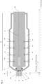
- This float plant has a melting furnace 2, also referred to as a melting tank, to which a glass mixture 3 to be melted is fed in a known manner and heated by means of burners 4 until a glass melt 5 of the desired composition is formed.
- a melting furnace 2 also referred to as a melting tank
- Other devices for homogenizing the glass melt are known to those skilled in the art and are therefore not described in more detail.
- the molten glass of the glass melt 5 passes through a channel 6, usually under the influence of gravity, onto a float bath 7 which contains liquid tin and on which the glass to be hot-formed 8 rests as part of its hot-forming under the influence of gravity, reducing its height can spread laterally.
- the tin bath 7 can be arranged in a float bath furnace 9, which also has burners 10 by means of which the temperature of the glass to be hot-formed can be adjusted.
- the molten glass 8 to be hot-formed is guided onto the tin bath 7 via an inlet lip 11, also referred to as a spout, which runs obliquely downwards and on which it already begins to widen.
- an inlet lip 11 also referred to as a spout
- cylindrical top rollers 12 as a pulling device, the further movement of the glass ribbon 13 forming on the tin bath 7 is influenced in a defined manner in its propagation movement from the side.
- the figures 1 and 2 are only two top rollers shown as an example, but more than two of these top rollers can be present and used as required.
- the glass ribbon 13 can optionally be transferred to an annealing furnace 14, which can also have burners 15 in order to subject the glass ribbon to a defined temperature reduction.
- the glass ribbon 13 After leaving the annealing furnace 14, the glass ribbon 13 is then available for further processing, in particular separation into glass panes or glass substrates.
- the X and Y direction spans a plane which extends horizontally and thus also runs essentially parallel to the surface of the tin bath 7 .
- Running perpendicular to this plane, the Z-direction extends upwards and thus also defines the normal direction in relation to the glass ribbon 13.
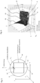
- figure 1 which as an apparatus for manufacturing a thin glass substrate, in particular a thin glass substrate with reduced draw-streaks, generally indicated by the reference numeral 1' provided float system includes, which of all with reference to figure 2 described facilities.
- the melting tank or the melting furnace 2 ′, a feed device for the glass batch 3 and the burners 4 are included as the device for melting 16 . Furthermore, the melting tank 2' has a channel 6' for transferring the molten glass 8 to be hot-formed onto the tin bath 7'.
- control slide valve 17 and thus the component for regulating the throughput of the glass stream, which is also referred to as a tweel, is arranged behind the channel 6'.
- the control slide or tweel 17 By shifting the control slide or tweel 17 in the direction of the double arrow shown next to the reference number 17, the cross section of the channel 6 can be narrowed or enlarged, whereby the quantity of the molten and hot-forming glass 8 emerging from the melting tank 2′ per unit of time is regulated and, in particular, set in a defined manner become.
- a feeder channel can be arranged between the melting tank 2' and the float bath furnace 9, in particular in front of the tweel 17, which in this case feeds the channel 6, in particular also over a longer distance than in figure 1 shown route forms.
- a more detailed description of throughput regulation can be found in DE 10 2013 203 624 A1 of the same applicant, which is also made the subject of the present application by reference.
- Seen in the direction of flow of the molten and hot-forming glass 8 is a device 18 for defined adjustment of the viscosity of the molten and glass 8 to be hot-formed in front of the tweel 17 and in front of the spout 11 .
- the device 18 for setting the viscosity in a defined manner can also be arranged directly in front of the spout.
- This device 18 for setting the viscosity in a defined manner comprises a chamber 19 which is separated from the melting tank 2' or can also form part of it and receives the molten glass 8 to be formed into a thin glass substrate for the purpose of setting its viscosity in a defined manner.
- the device 18 for the defined adjustment of the viscosity comprises areas 20, 21 through which fluid flows, in particular areas through which water flows, which absorb heat from the glass 8 to be hot-formed and can be designed as a metallic tube system.
- This metallic pipe system can also be colored for better heat absorption or provided with a temperature-resistant paint on its surface.
- the walls 22, 23, 24 and 25 of the chamber 19 can also absorb heat from the glass 8 to be hot-formed, in that their temperature is set in a defined manner, for example by further cooling devices.
- the walls 22, 23, 24 and 25 of the chamber 19 can also be designed spatially separate from the melting tank 2' and have high-temperature-resistant metallic walls in order to provide improved heat dissipation. as follows with reference to figure 3 is described in more detail.
- the device 18 for the defined setting of the viscosity comprises at least one cooling device, by means of which the temperature and thus also the viscosity of the glass 8 to be hot-formed can be set in a defined manner.
- Viscosity measurements are well known to those skilled in the art.
- a viscosity measurement or determination of the viscosity ⁇ can also be undertaken by measuring the temperature T of the respective glass at the specified location and a corresponding subsequent conversion of the temperature T into viscosity values ⁇ .
- the temperature-viscosity curve for the respective glass can then be used to convert the temperature values T into viscosity values ⁇ .
- This temperature-viscosity curve can be determined in advance by measuring the viscosity ⁇ of the respective glass in a conventional manner for each temperature T to be measured.
- the corresponding coefficients To, A and B for the respective glass can first be determined experimentally and then used to determine the viscosity ⁇ .
- the value of the measured temperature T then defines the correspondingly measured value of the viscosity ⁇ and converted using this equation.
- Non-contact and alternatively or additionally direct temperature measurements in contact with the glass to be measured are known to the person skilled in the art.
- Corresponding sensors are described, for example, with the sensory device or unit 26 within the scope of this disclosure.
- the sensory device or unit 26 can be in direct contact with the glass and can thus measure the temperature directly, or it can also include a radiation measuring device, which detects the temperature by detecting the spectrum emitted by the glass 8 to be hot-formed using the spectrum itself and/or the intensity of the emitted radiation.
- the sensory device 26 can be arranged at a location directly in front of the tweel 17 and in direct proximity to its front side in the direction of flow or like this, for example, also to the figure 1 can also be seen to be arranged at a short distance from the tweel 17 .
- further sensory units can also be arranged at further locations, in particular at further locations spaced apart in the direction of flow, for example a further sensory unit can also be at the beginning of bay 1 at a distance in the drawing direction of up to 1.5 m after the tweel and also at the beginning of the bay 4 thus at a distance of up to 12 m after the tweel in the drawing direction, without this being placed independently in figure 1 was shown again.
- the device 1' for producing a thin glass substrate, in particular a thin glass substrate with reduced stretch marks comprises a device 47 for hot forming, which below also with reference to figure 3 is described in more detail, which is located behind the device 18 for the defined setting of the viscosity in the flow or drawing direction and receives the glass 8 to be hot-formed via the spout 11 .
- the spout 8 directs the glass 8 to be hot-formed onto a tin bath 7' which is accommodated in the float bath furnace 9'.
- a tin bath 7' which is accommodated in the float bath furnace 9'.
- transverse webs 27 to 31 which divide the tin bath into several bays 32 to 37.
- Float pools are usually divided into 7 or 8 bays, whereas in figure 1 by way of example, only six consecutive bays, these are bay 1 to bay 6 with the reference symbols 32 to 37, are shown. It will also click on for further description DE 10 2006 051 637 A1 referenced, in which float baths with corresponding bays are disclosed.
- top rollers 38 to 44 are arranged next to the top roller 12 ′ for the mechanical movement of the glass ribbon 13 .
- the distance from the end of the tweel 17 in the pulling or flow direction is 1.5 m and up to the start of bay 4, which has the reference number 35, the distance from the end of the Tweels 17 in the drawing or flow direction 12 m, like this also in the X-direction scaled representation of the Cartesian coordinate system of figure 3 can be seen.
- FIG 3 an alternative or additional configuration of the device 18 for the defined setting of the viscosity can also be seen.
- the molten glass 8 is in a channel 6 'from the in figure 3 melting tank 2', not shown, leads to the float bath furnace 9'.
- the walls 45, 46 of the channel 6' are formed from a high-temperature-resistant metal, for example platinum, which can also be arranged as a metallic layer on a mineral refractory material.
- the sensory unit 26 described above can preferably be arranged in the vicinity of the tweel 17 .
- the device 47 for hot forming which comprises a float device, in particular a float bath furnace 9' with a tin bath 7'.
- the invention can also include a down-draw drawing device, in particular an overflow-down-draw-fusion drawing device, which is not shown in the figures and the method is not only a float method, but also a dow-draw Methods, in particular an overflow fusion down-draw method.
- a down-draw drawing device in particular an overflow-down-draw-fusion drawing device, which is not shown in the figures and the method is not only a float method, but also a dow-draw Methods, in particular an overflow fusion down-draw method.
- FIG. 1 shows the course of the viscosity of the glass 8 or glass ribbon 13 located on the float bath 7' in the flow or drawing direction along the center line M, which is also referred to as the Y-direction of the Cartesian coordinate system, and in this case indicates the respective viscosity ⁇ of the glass 8 or glass ribbon 13 as a function of the location in the Y direction.
- an arrow 48 is indicated at a Y-direction location in front of the tweel 17 and in front of the spout 11 .
- this location in the Y-direction is directly in front of the tweel, thus directly in front of its front end as seen in the direction of flow.
- the arrow 49 is located in the Y-direction at the location which corresponds to the rear end of the tweel 17 in the flow or pull direction, and thus also designates the location immediately behind the tweel 17 on which the spacing and distance specifications disclosed here are based.
- the arrow 50 is in the Y-direction at a distance of 1.5 m from this rear end of the tweel 17 and thus at a location which, in a preferred embodiment, corresponds to the beginning of the bay 1 in the flow or pulling direction.
- the arrow 51 is located in the Y-direction at a distance of 12 m from the rear end of the tweel, which corresponds to the start of the bay 4 in the flow or pulling direction in this preferred embodiment.
- a method according to the invention for the production of a thin glass substrate preferably for the continuous production of a thin glass substrate, in particular a thin glass substrate with reduced drawing strips, can be carried out with the devices and devices described above.
- the viscosity ⁇ of the glass 8 to be formed, in particular to be hot formed, or at least partially formed glass 13 is set in a defined manner for the thin glass substrate to be obtained.
- This defined adjustment of the viscosity ⁇ is carried out before delivery to a device for hot-forming 47, in particular before delivery to a float bath oven 9', in particular a defined cooling of the glass 8 to be hot-formed being carried out by means of the device 18.
- the viscosity ⁇ is adjusted before the lip stone or the inlet lip for dispensing the liquid glass, the spout 11, and takes place in particular before dispensing onto a metal bath, the tin bath 7' of the float bath furnace 9'.
- the viscosity can also be adjusted upstream of the control slide, i.e. the component for regulating the throughput of the glass flow, the tweel 17 .
- the temperature of the glass to be formed or at least partially formed can be at least 1000 °C and at most 1100 °C and/or before the tweel for the glass for which the following measurements of the drawing strips or elongated elevations on the surface and its thickness are described at the beginning of bay 1 thus at a distance in the drawing direction of up to 1.5 m at least 850 °C and at most 910 °C and/or at the beginning of bay 4 thus at a distance in the drawing direction of up to 12 m after the tweel at least 720°C and not more than 760°C. In each case, there was a maximum temperature deviation of at most 10 °C
- the end of the channel 6′ of the melting tank 2′ lies directly in front of the tweel.
- the specifications for the respective viscosities apply in each case at least to the middle of the glass 8 or glass ribbon 13, viewed in each case in the X and Z direction.
- the viscosities described above could be achieved particularly well in plants for the hot forming of a thin glass substrate with a throughput of less than 400 t, preferably 200 t, particularly preferably 100 t glass per day.
- the proportion of good glass per day was more than 15% of the total glass throughput.
- Good glass is understood to mean a glass substrate in which the maximum height H of the elevations described here or thus the maximum height H of the draw strips on average with arithmetic averaging, adjusted for wedge-shaped fluctuations in thickness and warping, of an analysis area of 10 * 10 cm 2 , preferably in the center of a hot-formed glass ribbon perpendicular to the drawing direction, was less than 100 nm and in which the transverse extension of the elevation is less than 40 mm.
- measured values of the thickness and the height are considered to have been corrected for wedge-shaped thickness fluctuations and warping if the influence of the wedge-shaped thickness change K and the warping V is reduced to a value of less than 5%.
- the glass from the melt in particular the glass that is specified below for the measurements of the surface and the thickness of the thin glass substrate and entered the device 18 for the defined setting of the viscosity from the melting tank 2 ', was in the device 18 with a first temperature of 1500° C., for example, and cooled to a second temperature of 1050° C., for example, for entry into the hot-forming process, and then transferred at this temperature to the device 47 for hot-forming.
- the cooling was at least 250° C., preferably 300° C., particularly preferably 450° C., and cooling of 500° C. was also possible with the device 18 .
- borosilicate glasses to be glasses that contain the following components (in % by weight): SiO 2 70 - 87 B2O3 _ 7 - 25 Na2O + K2O 0.5 - 9 Al2O3 _ 0 - 7 CaO 0 - 3
- a first preferred borosilicate glass has the following composition and comprises: SiO 2 70-86% by weight Al2O3 _ 0-5 wt% B2O3 _ 9.0-25% by weight Well 2 O 0.5-5.0% by weight K2O 0-1.0% by weight Li2O 0-1.0% by weight,
- a second preferred borosilicate glass is an alkali borosilicate glass with good thermal toughening properties. It contains SiO 2 78.3-81.0% by weight B2O3 _ 9.0-13.0% by weight Al2O3 _ 3.5-5.3% by weight Well 2 O 3.5-6.5% by weight K2O 0.3-2.0% by weight CaO 0.0-2.0% by weight
- Aluminosilicate glasses can preferably have the following composition in % by weight: SiO 2 55 to 65 Well 2 O more than 12 to 17 Al2O3 _ 16.5 to 20 K2O 2 to 4.4 MgO 3.9 to 10 ZrO 2 0 to 5 ZnO 0 to 4 CaO 0 to 4 Na2O + K2O + MgO + ZnO + CaO 15 to 28 SnO 2 0 to 1 TiO2 + CeO2 less than or equal to 1.
- Lithium aluminosilicate glasses can have a composition that contains the following components (in % by weight): SiO 2 60 to 75 Al2O3 _ 10 to 28 and Li2O 3 to 15
- the second pane comprises a thin glass substrate hot-formed using the method according to the invention with a lithium aluminum silicate glass with an Li 2 O content of 4.6% by weight to 5.4% by weight and an Na 2 O content of 8.1% by weight to 9.7% by weight .-% and an Al 2 O 3 content of 16 wt .-% to 20 wt .-%.
- the first pane in a laminated glass in particular for a motor vehicle, comprises a lithium aluminum silicate glass with an Li 2 O content of 4.6% by weight to 5.4% by weight. and an Na 2 O content of 8.1% to 9.7% by weight and an Al 2 O 3 content of 16% to 20% by weight.
- one or more of the components SnO 2 , CeO 2 , P 2 O 5 and ZnO can optionally be included in a total proportion of 0% by weight to 2.5% by weight.
- one or more of the components SnO 2 , CeO 2 , P 2 O 5 and ZnO can be included in a total proportion of 0.25% by weight to 1.6% by weight.
- FIG 15 shows schematically and not to scale a laminated glass pane 59, which comprises a first pane 60, a polymeric layer 61, which is arranged between the first pane 60 and the second pane 62 and connects them, and finally the second pane 62.
- the laminated glass pane may comprise more than two panes. This can be the case, for example, if particularly high mechanical loads are expected and a correspondingly high strength of the laminated glass pane is desired.
- the polymeric layer 61 has a thickness between at least 0.5 mm and at most 1.7 mm. It can be designed as a film, for example as a film comprising EVA and/or polyvinyl butyral, or as a layer which comprises a number of films, or as a multi-layer film. But it is also possible that the polymeric formed layer by applying monomers to one of the two disks 60, 62 and by starting a polymerization reaction to form the polymerically formed layer in situ. It is also generally possible for the polymeric layer 61 to be formed from a composite of foils. In particular, the films can also include PET and/or PE. In a multilayer film, the layers can have different compositions and physical properties. In general, the film or a layer of a multi-layer film can have a low-E or a so-called solar control coating.
- the first pane 60 is thicker than the second pane 62. This is advantageous, for example, if the first pane has a lower intrinsic strength than pane 62, so that to ensure sufficient overall strength of the laminated glass pane 59, the Thickness of the first disc 2 is increased accordingly.
- the second pane 64 preferably has a thickness of between at least 0.3 mm and at most 1.5 mm and can include or consist of the thin glass substrate 54 described here.
- a thickness of between at least 0.3 mm and at most 1.5 mm can include or consist of the thin glass substrate 54 described here.
- the thickness of the thin glass substrate 54 with the reference symbol D is only in figure 15 the thickness of the thin glass substrate 54 with the reference symbol D, but also given as a disclosure for all other embodiments of the thin glass substrate 54 described here.
- the glasses of the first and second panes 59, 62 are preferably matched to one another in such a way that the temperatures at which the two glasses of the first and second panes are in the viscosity range between 107 dPas and 1010 dPas have the same viscosity, only differ from one another by a maximum of 50° C., preferably by a maximum of 30° C., particularly preferably by a maximum of 20° C. and very particularly preferably by a maximum of 10° C.
- the second disk 62 is preferably present as a chemically prestressed disk, preferably as a chemically prestressed disk with a compressive stress zone of at least 40 ⁇ m thickness, the compressive stress being at least 150 MPa and at most 900 MPa.
- the compressive stress is at most 800 MPa, preferably at most 600 MPa.
- Such a compressive stress is obtained in particular by prestressing using a sodium nitrate-potassium nitrate mixture.
- the compressive stress is at most 500 MPa, preferably at most 400 MPa, particularly preferably at most 300 MPa and very particularly preferably at most 250 MPa.
- Such compressive stresses can be achieved in particular by prestressing using a pure sodium nitrate melt.
- the laminated glass pane 1 is a curved laminated glass pane, in particular a motor vehicle pane, so that the outward-facing side of the second pane 62 is concave.
- the thin glass substrate of the second pane 62 produced according to the invention can be subject to slight changes in thickness of the thickness D.
- the laminated glass pane 59 shown can, in particular when used as a motor vehicle pane, form a reflective surface 65 for a head-up display, in particular if this is used in a head-up display for vehicles operated on land, on or in water and in the air, in particular motor-driven vehicles is used.
- the first panel 60 may face the outside of the vehicle and the second panel 62 may face the inside of the vehicle.
- the reflection surface 65 for a head-up display can lie on the surface 63 of the second pane 62 that then points into the interior of the vehicle.
- the reflective surface 65 can extend over the entire surface 63 or only over a portion of the surface 63, which is exemplified by a double arrow 66 in FIGS Figures 15 and 16 is shown. Head-up displays are well known to those skilled in the art and consequently do not require any further detailed description.
- the second pane 62 has a zebra angle of greater than or equal to 45°, in particular greater than or equal to 50°, particularly preferably greater than or equal to 55°, with a thickness of 0.7 mm.
- zebra angle and the ring-on bending strength mentioned below reference is made to the priority application DE 10 2016 125 488 referenced, which is also made the subject of the present application by incorporation.
- the second washer 62 has a ring-on-ring flexural strength more than 150 MPa, in particular more than 250 MPa, preferably more than 300 MPa, further preferably more than 400 MPa, particularly preferably more than 500 MPa and very particularly preferably more than 600 MPa and less than 900 MPa.
- the laminated glass pane 1 is designed according to a further embodiment such that the second pane 4 with a thickness of 0.7 mm and a wavelength of 840 nm has a transmission of more than 91.5% at a wavelength of 560 nm of more than 91.5% and at 380 nm greater than 90%. As already mentioned above, this is particularly advantageous for realizing a good view through pane 1, so that passenger safety is further improved in this way.
- the laminated glass pane 59 is preferably designed in such a way that the temperatures at which the glasses of the first pane 60 and the second pane 62 have the same viscosity values in the viscosity range between 107 dPas and 1010 dPas only differ from one another by a maximum of 50° C. with the same viscosity in each case , preferably by a maximum of 30 ° C, more preferably by a maximum of 20 ° C and most preferably by a maximum of 10 ° C from each other.
- the second disk 62 is chemically prestressed substantially by exchanging lithium ions for sodium ions.
- a pane is referred to as "essentially prestressed by exchanging lithium ions for sodium ions" if the major part of the prestress, i.e. at least 80% of the prestress generated, is due to the exchange of lithium ions for Sodium ions is due.
- a disk is said to be prestressed essentially by exchanging lithium ions for sodium ions if the prestressing is obtained exclusively through this exchange.
- FIG. 16 shows the embodiment of a laminated glass pane 59, which in particular can be a motor vehicle pane.
- a first pane 60 a polymeric layer 61 and a second pane 62 are encompassed by the laminated glass pane 59 .
- the laminated glass pane 59 is curved. It is possible that, as illustrated, the thickness of the individual panes 60, 62 and that of the polymeric layer 61 tapers from the middle of the laminated glass pane 59 towards the edges.
- the thickness of the individual panes 60, 62 and also the polymeric layer 61 may be constant in each case, or for only individual layers 60, 61, 62 that make up the laminated glass pane 59 to have a thickness that varies over the cross section of the pane 59 .
- one or more of the layers may be wedge-shaped.
- the laminated glass pane 59 is designed in such a way that the surface 63 of the second pane 62 pointing outwards is curved in a concave manner.
- the laminated glass pane 59 can also be designed in such a way that the outwardly facing surface 64 of the first pane 60 is curved in a concave manner.
- one or more of the components SnO 2 , CeO 2 , P 2 O 5 and ZnO can be included in a total proportion of 0.5% by weight to 1.0% by weight.
- the thin glass substrate in particular the second pane of a laminated glass, has the following composition in mol %: 60 to 70 SiO 2 10 to 13 Al2O3 _ 0.0 to 0.9 B2O3 _ 9.6 to 11.6 Li2O 8.2 to less than 10 Well 2 O 0.0 to 0.7 K2O 0.0 to 0.2 MgO 0.2 to 2.3 CaO 0.0 to 0.4 ZnO 1.3 to 2.6 ZrO 2 0.0 to 0.5 P2O5 _ 0.003 to 0.100 Fe2O3 _ 0.0 to 0.3 SnO 2 0.004 to 0.200 CeO2 .
- the following ratios preferably apply to the composition of the lithium aluminum silicate glass: ( Li2O + Al2O3 )/( Na2O + K2O ) > 2 , 0.47 ⁇ Li2O /( Li2O + Na2O + K2O ) ⁇ 0.7 0.8 ⁇ CaO+ Fe2O3 + ZnO+ P2O5 + B2O3 + CeO2 ⁇ 3 , wherein at least four of the six oxides are included in the glass composition.
- the lithium aluminum silicate glass preferably has a glass transition temperature T g of less than 540° C. and/or a processing temperature of less than 1150° C.
- the thin glass substrates obtained with the method according to the invention were analyzed and calculated after the measurement in terms of their dimensions in the z-direction and in terms of their optical properties, and the reduction in stretch marks compared to conventional methods was determined.
- measurements were taken on both main surfaces to determine thickness deviations from an ideally planar thin glass substrate as thickness measurements of the thin glass substrate, and in a second series of measurements, measurements were taken of the elevations or drawing strips on the upper main surface of the thin glass substrate 54.
- the data from the first series of measurements thus record the optical effect of a thin glass substrate in which the light passes through the upper and lower main surface and also describe this effect on the basis of the resulting optical refractive powers, which are formed by both surfaces. Influences, for example, on optical beam paths for sensory devices arranged behind the thin glass substrate 54, which are used, for example, for sensory detection of the surroundings of a motor vehicle, can thereby be described.
- the data from the second series of measurements record the optical effects of only one main surface, such as those that occur, for example, with thin glass substrates 54 used in transmitted light, if they are ground and polished on one side, for example, or are made of a material with the same refractive index on one side, for example in a laminated glass pane are embedded.
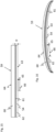
- figure 5 shows a schematic representation of a measuring field for measuring the optical path length between the upper main surface and the lower main surface and thus dimensions in the Z-direction.
- a laser interferometer in particular using a phase shift interferometer, measurements were carried out which extended over the entire upper main surface 53 of the thin glass substrate 54 .
- the main surface of a thin glass or glass substrate is usually referred to as the two opposite sides of the substrate which each have the greatest areal extension.
- An analysis field 52 is also shown, in which the evaluations described below were carried out, the results of which are given in Table 1.
- contour lines V L1 and V L2 are also shown by way of example, which only schematically indicate a warping V compared to an ideally planar thin glass substrate 54 and reproduce it in a greatly exaggerated manner for the sake of clarity.
- Such bulges V typically rise in the positive or negative Z-direction in relation to the main planes of an ideally planar thin glass substrate 54 and can be symmetrical in the drawing or Y-direction, in particular symmetrical to the center line M and with its longitudinal direction in the drawing - Or extend in the Y direction.
- the contour lines V L1 and V L2 are only shown as an example for the analysis field 52 due to the following metrological explanations, such curvatures can also extend over the entire thin glass substrate 54 .
- the warp value V indicates the maximum distance of a point on a main surface of the warped thin glass substrate relative to a corresponding point on the main surface of an ideally planar thin glass substrate.
- the thin glass substrate was separated from the glass ribbon 13 in the form of a rectangular substrate after carrying out the method according to the invention.
- the measurements of Thickness deviation were in the in figure 5 shown shape on a circular measuring surface with a diameter of 300 mm subjected to the measurement.
- a conventional thin glass substrate was also separated from a glass ribbon in the same way and subjected to the following measurement and evaluation. Care was taken to ensure that all of the measured thin glass substrates were removed from the center of the glass ribbon, perpendicular to the drawing direction, and thus from the center of the glass ribbon 13 in the x-direction, after hot forming.
- Measurements were taken on the main surface 53 in the Z-direction of the Cartesian coordinate system and the thin glass substrate 54 lay on a flat base with its main surfaces parallel to the X-Y plane, as was the case for all other measurements disclosed here.
- Measurements of the thickness deviation of an ideally flat glass substrate were made, which are also referred to as thickness variation D m /m in Table 1, and measurements of the elevation of the two main surfaces in the z-direction by measuring the optical path length difference between the upper and lower main surface with respect to of an ideally planar glass substrate.
- the laser interferometer was a Fizeau interferometer with an aperture of 300 mm.
- a Zygo Verifire system with a measuring spot of 30" (circular) was used.
- the measurement uncertainty in the Z-direction was ⁇ 30 nm, corresponding to lambda/20 at a wavelength of 633 nm.
- the lateral uncertainty in the X and Y directions was 0.31 mm.
- Piston Zernike Removal was enabled and data was used only to suppress the influence of a wedge-shaped thickness change K and a warp V and using the Zygo Mx software (version 7.0.0.15) with a Gaussian Spline Filter high-pass with a cutoff of 40mm.
- the Spline Beaton Coefficient and Spline Tension Controls were set to Default Settings.
- the influence of the wedge-shaped change in thickness K and the warping V could be reduced to a value of less than 5% with the filtering described above in relation to the measurement result of the measurement of the respective fluctuation in thickness D m /m. This allowed the measurement of the thickness variation D m / m at each location Wedge-shaped thickness fluctuations and warping are eliminated from the measurement.
- both the upper main surface 53 as values z top (x) and the lower main surface with values z bottom (x ) of the thin glass substrate is measured at location y 54, whose refractive powers P top (x) and P bottom (x) are determined and from this the total refractive power P total (x) of the thin glass substrate 54 is specified or just the refractive power P top (x) or P bottom (x) of only one of the two main surfaces of the thin glass substrate 54 can be specified.
- P top (x), P bottom (x) determined from the measured values by means of Fourier interferometry of the second series of measurements described below and P total (x) measured by means of the white light interferometer, in particular the zygo white light interferometer of the first series of measurements, are considerably more precise Specifications for the optical performance of a thin glass substrate, in particular for the achievable resolution and the contrast to be obtained within an optical system, than conventional shadow casting methods could achieve.
- the thin glass substrates produced according to the invention are part of a Windscreen projection device, in particular a head-up display, for vehicles operated on land, on or in water and in the air, or if optical sensors for detecting the surroundings of such a vehicle are arranged behind them.
- This glass could contain one or more of the components SnO 2 , CeO 2 , P 2 O 5 and ZnO in a total proportion of 0.25% by weight to 1.6% by weight.
- the square analysis field 52 of figure 5 which was evaluated for Table 1 below, had a size of 18*18 cm 2 .
- this deflection angle can be calculated with the measured ones available here Values as follows are each determined for one of the main surfaces of the thin glass substrate, for example with the method disclosed here of the second measuring range by means of Fourier interferometry. The deflection angle is then calculated from the available values using the following formula in arc minutes: ArcTan e.g ′ x 60 This deflection angle essentially corresponds to the conventional measurement method and consequently this value can also be provided using the measurement and analysis method described above.
- the measured values obtained in the second series of measurements with the Fourier transform white light interferometer, FRT interferometer, for the upper surface, i.e. the main surface 53, of the above-mentioned thin glass substrate 54 are shown in arbitrary units in a perspective view.
- elevations were formed on the main surface 53 of the thin glass substrate 54, in particular elongated elevations, which rise essentially in the normal direction and thus in the Z direction and with their longitudinal extension essentially in the drawing direction and thus in the Y extend direction.
- the longitudinal extension in the Y direction was more than twice, in particular more than three times, and usually more than five times the transverse extension of the respective elevation in the X direction.
- These elevations also known as pull strips, carry in figure 6 the reference numerals 55 to 58.
- the transverse extent Q of the elevation 57 in the x-direction is shown with a double arrow Q and designates the greatest extent of an elevation perpendicular to its longitudinal direction, thus transverse to the longitudinal direction of the elevation or of the pull strip, which is formed by this elevation.
- the reference character K represents a wedge-shaped change in thickness and the reference symbol V represents a warping in relation to an ideally planar surface.
- these elevations forming drawing strips had a height H in the Z-direction which, on average, was adjusted for wedge-shaped fluctuations in thickness and warpage with arithmetic averaging over the analysis surface 52 of the figure 11 of 10*10 cm 2 , preferably measured in the center of a hot-formed glass ribbon perpendicular to the drawing direction, and thus smaller than 100 nm in the X-direction in every measured case.
- the measured thin glass substrate 54 even had a height H of the elevations in the Z-direction, which on average, adjusted for wedge-shaped thickness fluctuations and warping, was less than 90 nm and even less than 80 nm.
- decimal exponents are each given as the values of E, using, for example, E-9 for the factor *10 -9 and E-3 for the factor *10 -3 for the sake of brevity.
- Table 1 also shows significantly reduced arithmetically average gradient values ( ⁇ D/ ⁇ x) m /(m/mm), which, with the equation given above for the deflection angles, also leads to significantly reduced average deflection angles. The same applies to the measured and analyzed values of the optical refractive powers.
- the refractive power for 97.5% of the measurement points was filtered as described above, and thus adjusted for the effects of the wedge-shaped change in thickness K and the warping V, and the averaged value of less than 282.4 mdpt and for the thin glass substrates produced according to the invention correspondingly a value of less than 63.0 mdpt.
- FIGs 7 to 10 represent further results in the form of grayscale images for illustration and show in each case figure 7 a gray scale representation of surface data obtained with the laser interferometer of the thin glass substrate 54 produced according to the invention, in which the thickness values of drawing strips can be recognized as gray values, in figure 8 a grayscale representation of the derivation in the X-direction of the thickness data obtained with the laser interferometer and thus varicose surface data of the thin glass substrate 54, in which the derivation values can be recognized as gray values.
- figure 9 shows a greyscale representation of optical refractive powers of the surface data of a conventional thin glass substrate obtained with the laser interferometer
- figure 10 a greyscale representation of optical refractive powers of a substrate produced according to the invention, in which the refractive powers can also be recognized as gray values.
- optical refractive powers of the thin glass substrate produced according to the invention are significantly lower than those of the conventional thin glass substrate.
- figure 11 shows similar to figure 5 a schematic representation of a measurement or analysis field 52, which extends over the entire upper main surface of the square thin glass substrate 54 with a size of 18*18 cm 2 .
- the contour lines K L1 , K L2 and K L2 are only shown as an example for the analysis field 52 due to the following metrological explanations, such wedge-shaped elevations can also extend over the entire thin glass substrate 54 .
- the value of the wedge-shaped change in thickness K gives the maximum distance of a point on a main surface of the thin glass substrate 54 with a wedge-shaped change in thickness relative to a corresponding point on the main surface of an ideally planar thin glass substrate.
- a Fourier transformation interferometer Microprof® (Art. MPR 200 30 with sensors FRT CWL 600 ⁇ m), manufactured by Fries Research & Technology GmbH, Friedrich-Ebert-Str., D-51429 Bergisch Gladbach, was used in the second series of measurements.
- the measurement was carried out on square areas with an area of 18*18 cm 2 , but only evaluated within the analysis field 52 for the measured values given here.
- 500 scans i.e. line-by-line measurements next to one another in the Y-direction, were carried out, each with 500 points and a point spacing in the X-direction of 0.36 mm.
- the rows were offset in the Y direction by a distance of 0.36 mm.
- the analysis field 52 was evaluated, i.e. the analysis field 52 from its upper main surface 53.
- the scanning unit (gantry design) was operated at a speed of 15 mm/s as the measuring speed, with a possible maximum speed of 300 mm/s).
- the lateral resolution was ⁇ 2 ⁇ m in the X and Y directions and the resolution in the vertical direction, i.e. in the Z direction, was 6 nm.
- the measurement direction of the individual scans along the respective measurement line was perpendicular to the drawing direction, i.e. in the X direction.
- the distance between the sensor and the measurement surface was approximately 3.74 mm with a thickness of the measured thin glass substrate of 0.7 mm.
- the values obtained were smoothed line by line in order to suppress high-frequency noise.
- the SAS JMP TM program was used for this purpose.
- the influence of the wedge-shaped change in thickness K and the warping V could be reduced to a value of less than 5% with the filtering described above in relation to the measurement result of the measurement of the respective height H.
- the measurement of the height at the respective location of the measurement could be corrected from wedge-shaped thickness fluctuations and warping.
- the analysis field 52 with the dimensions of 10*10 cm 2 was also used as a basis for the respective arithmetic mean for the data of the upper main surface 53 obtained as described above.
- FIG. 12 shows an example of a gray scale representation of surface data of a thin glass substrate 54 produced according to the invention, obtained with the FRT interferometer, in which the thickness values of drawn strips can be recognized as gray values.
- Figures 13 and 14 A comparison of the conventional thin glass substrates produced according to the invention is denoted Figures 13 and 14 to see which ones figure 13 a greyscale representation of optical refractive powers of the surface data of a conventional thin glass substrate obtained with the FRT interferometer and figure 14 a grayscale representation of optical refractive powers of the surface data of the upper main surface of a thin glass substrate 54 produced according to the invention, obtained with the FRT interferometer.
- elevations could be formed on one of the main surfaces of the thin glass substrate, in particular elongated elevations, which essentially rise in the normal direction, which have a longitudinal extension greater than twice, preferably three times, particularly preferably five times one
- the transverse extension of the elevation and have a height H which is less than 100 nm, preferably less than 90 nm, particularly preferably less than the arithmetic mean when averaging an analysis area of 10 * 10 cm 2 , preferably in the middle of a hot-formed glass ribbon perpendicular to the drawing direction than 80 nm and in which the transverse extent of the elevation was less than 40 mm in each case.
- 97.5% of the measuring points of the thin glass substrate hot-formed according to the invention had a deviation in the Z-direction, i.e. the maximum elevation of the drawing strips, of less than 173.9 nm and for the conventionally formed thin glass substrate it was 273.5 nm.
- the value of ( ⁇ D/ ⁇ x) m /(m/mm) was less than 57.1 for the heat-formed glass according to the invention and 78.3 for the conventionally formed glass.
- the value of the refractive power on one side was less than 22.3 mdpt for the conventionally formed thin glass substrate and less than 17.5 mdpt for the thin glass substrate hot-formed according to the invention.
- the thin glass substrate 54 With the method for producing a thin glass substrate, the thin glass substrate 54 essentially had a wedge-shaped change in thickness K over a length of 1 m perpendicular to the drawing direction, thus in the X-direction, due to hot forming, a value of less than 100 ⁇ m. Furthermore, as a result of the hot forming, the thin glass substrate 54 had a warping V over a length of 1 m perpendicular to the drawing direction, ie in the X direction, with a value of less than 600 ⁇ m.
- the thin glass substrate 54 having an average thickness averaged over an area of the first and second main surfaces of the thin glass substrate 54 of at least 10 cm ⁇ 10 cm of 0.3 mm to 2.6 mm could be obtained by the hot forming.
- thin glass substrate 54 with a thickness of 0.7 to 2.5 mm could also be obtained, as well as particularly preferred embodiments with a thickness of approximately 0.7 mm or a thickness of approximately 2.54 mm.
- glass substrates with a thickness of up to 10 mm or even a thickness of up to 12 mm could even be produced with the method according to the invention.
Description
Die Erfindung betrifft ein Verfahren zur Herstellung eines Dünnglassubstrats. Ferner werden Messverfahren zur Ermittlung der optischen Qualität insbesondere von verfahrensgemäß hergestellten Dünnglassubstraten angegeben.The invention relates to a method for producing a thin glass substrate. Furthermore, measurement methods for determining the optical quality, in particular of thin glass substrates produced according to the method, are specified.
Dünnglassubstrate sind von zunehmender Bedeutung, auch in der Kraftfahrzeugtechnik, da mit diesen nicht nur das Gewicht des Kraftfahrzeugs gesenkt, sondern auch die optischen Eigenschaften von dessen Verglasung maßgeblich beeinflusst werden können.Thin glass substrates are of increasing importance, also in motor vehicle technology, since they not only reduce the weight of the motor vehicle, but also the optical properties of its glazing can be decisively influenced.
Mit zunehmenden Anforderungen an die optischen Eigenschaften dieser Substrate, beispielsweise bei der Einblendung von zweidimensionalen Informationen in Rückprojektion oder bei der sensorischen Erfassung optischer Daten aus dem Umfeld des Kraftfahrzeugs entsteht ein zunehmender Bedarf an optisch hochwertigen Dünnglassubstraten und entsprechenden Weiterentwicklungen zur Verminderung von deren Gewicht. Insbesondere in der E-Mobilität, somit bei elektrisch angetriebenen Fahrzeugen, kommt der Gewichtsreduktion der Verglasung des Fahrzeugs hohe Bedeutung zu.With increasing demands on the optical properties of these substrates, for example when displaying two-dimensional information in rear projection or when capturing optical data from the area around the motor vehicle by sensors, there is an increasing need for optically high-quality thin glass substrates and corresponding further developments to reduce their weight. In particular in e-mobility, i.e. in electrically driven vehicles, the weight reduction of the glazing of the vehicle is of great importance.
Das Dokument
Das Dokument
Die
Der koreanischen Patentanmeldung
Der Erfindung liegt die Aufgabe zugrunde, ein Verfahren zur Herstellung eines Dünnglassubstrats mit verbesserter optischer Qualität bereitzustellen.The object of the invention is to provide a method for producing a thin glass substrate with improved optical quality.
Diese Aufgabe wird mit dem in Anspruch 1beschriebenen Verfahren gelöst. Vorteilhafte Weiterbildungen sind den jeweiligen abhängigen Ansprüchen sowie der Beschreibung zu entnehmen.This object is achieved with the method described in
In überraschender Weise haben die Erfinder herausgefunden, dass diese Ziehstreifen mit einem Verfahren zur Herstellung eines Dünnglassubstrats, vorzugsweise zur kontinuierlichen Herstellung eines Dünnglassubstrats, insbesondere eines Dünnglassubstrats mit verminderten Ziehstreifen, verminderbar sind, bei welchem nach dem Schmelzen und vor einer Heißformung die Viskosität des zu formenden oder zumindest teilweise geformten Glases für das zu erhaltende Dünnglassubstrat definiert eingestellt wird und das heißzuformende Glas vor Abgabe an eine Einrichtung zur Heißformung in dessen Viskosität definiert eingestellt, insbesondere durch eine definierte Abkühlung eingestellt wird. Alle nachfolgenden Angaben, insbesondere numerischen Angaben zur Viskosität sind in lg η /dPas angegeben, auch wenn dieses um der Kürze Willen und wie auf diesem technischen Gebiet üblich nicht immer explizit angegeben wird.Surprisingly, the inventors have found that these pull marks can be reduced using a method for manufacturing a thin glass substrate, preferably for the continuous manufacture of a thin glass substrate, in particular a thin glass substrate with reduced pull marks, in which, after melting and before hot forming, the viscosity of the material to be shaped or at least partially formed glass is set in a defined manner for the thin glass substrate to be obtained and the viscosity of the glass to be hot-formed is set in a defined manner before delivery to a device for hot-forming, in particular by defined cooling. All of the following information, in particular numerical information on viscosity, is given in lg η /dPas, even if this is not always explicitly stated for the sake of brevity and as is customary in this technical field.
Als Verminderung der Ziehstreifen wird hierbei verstanden, dass eine Verminderung der Größe der Ziehstreifen eintritt, dies bedeutet des Volumens der durch die Ziehstreifen gebildeten Erhebungen gegenüber einem ideal planen Substrat, insbesondere Dünnglassubstrat. Zum Vergleich der Verminderung dient hierbei ein Verfahren, bei welchem die Viskosität des heißzuformenden Glases vor vor dem Lippenstein für die Abgabe des flüssigen Glases, dem Spout, welcher auch als Einlauflippe bezeichnet wird, beispielsweise lg η / dPas 3,47 betrug, welches in der nachfolgenden detaillierten Beschreibung noch detaillierter anhand konkreter Messergebnisse dargelegt wird. Sowohl bei den erfindungsgemäß hergestellten Gläsern als auch den herkömmlichen Vergleichsgläsern wurden für die nachfolgenden Vergleichsmessungen jeweils Gläser mit einer Zusammensetzung verwendet, wie diese für das Dünnglassubstrat beispielhaft in Anspruch 28 angegeben und bei der nachfolgenden Beschreibung der am Dünnglassubstrat durchgeführten Messungen noch stärker konkretisiert wird.A reduction in the pull strips is understood here to mean that a reduction in the size of the pull strips occurs this means the volume of the elevations formed by the pull strips compared to an ideally planar substrate, in particular a thin glass substrate. To compare the reduction, a method is used here in which the viscosity of the glass to be hot-formed before the lip stone for dispensing the liquid glass, the spout, which is also referred to as the inlet lip, was lg η / dPas 3.47, for example the following detailed description is explained in more detail based on concrete measurement results. Both in the case of the glasses produced according to the invention and the conventional comparison glasses, glasses with a composition were used for the following comparison measurements, as specified for the thin glass substrate by way of example in
Ferner wird allgemein ein Dünnglassubstrat als Dünnglassubstrat mit verminderten Ziehstreifen verstanden, bei welchem Erhebungen auf einer der Hauptoberflächen des Dünnglassubstrats, insbesondere langgezogene Erhebungen, welche sich im Wesentlichen in Normalenrichtung erheben und bei welchen eine Längserstreckung größer als das Zweifache, bevorzugt Dreifache, besonders bevorzugt das Fünffache einer Quererstreckung der Erhebung ist, welche eine Höhe aufweisen, die im Mittel, bereinigt von keilförmigen Dickenschwankungen und Verwölbungen bei arithmetischer Mittelung einer Analysefläche von 10 * 10 cm2, vorzugsweise in der Mitte eines heißgeformten Glasbands senkrecht zur Ziehrichtung, kleiner als 100 nm, bevorzugt kleiner als 90 nm, besonders bevorzugt kleiner als 80 nm ist und bei welchen die Quererstreckung der Erhebung jeweils kleiner als 40 mm ist.Furthermore, a thin glass substrate is generally understood as a thin glass substrate with reduced pull strips, in which elevations on one of the main surfaces of the thin glass substrate, in particular elongated elevations, which essentially rise in the normal direction and in which a longitudinal extent is greater than twice, preferably three times, particularly preferably five times a transverse extent of the elevation, which have a height which, on average, adjusted for wedge-shaped thickness fluctuations and warping with arithmetic averaging of an analysis area of 10*10 cm 2 , preferably in the center of a hot-formed glass ribbon perpendicular to the drawing direction, is preferably less than 100 nm is less than 90 nm, particularly preferably less than 80 nm and at which the transverse extension of the elevation is less than 40 mm.
Frühere mathematische Modelle haben nahegelegt, dass höhere Verarbeitungstemperaturen auch höhere optische Qualität bereitstellen, weshalb die mit einer Temperaturabsenkung einhergehende erhöhte Viskosität zunächst nicht als erfolgversprechende Maßnahme zur Erzielung verbesserter optischer Qualität erschien.Earlier mathematical models have suggested that higher processing temperatures also provide higher optical quality, which is why the increased viscosity associated with a temperature reduction initially did not appear to be a promising measure for achieving improved optical quality.
Insbesondere bei der kontinuierlichen Herstellung von Dünnglassubstraten wurde bisher Wert daraufgelegt, die Strecke zwischen der das heißzuformende Glas abgebenden Schmelzwanne und dem ein flüssiges Metall umfassenden Floatbad räumlich möglichst kurz und verfahrenstechnisch direkt zu gestalten. Ferner sind mit niedrigen Temperaturen einhergehende höhere Viskositäten des zu erschmelzenden Glases für Schmelzwannen eher nachteilig, da sich mit zunehmender Viskosität auch die Homogenisierung des Glases schwieriger gestalten kann. Ferner steht eine Abkühlung des heißzuformenden Glases regelmäßig einem hohen Durchsatz entgegen, da das dann nur zäher fließende Glas innerhalb der heißformenden Prozesskette die Tendenz aufweist, die Durchflussgeschwindigkeit zu senken. Besonders nachteilig erschien deshalb bisher ein die Temperatur absenkender Eingriff in die Prozesskette der Heißformung, insbesondere wenn dieser zu einem frühen Zeitpunkt erfolgte und somit die gesamte Prozesskette betraf.Particularly in the continuous production of thin glass substrates, value has been placed on making the distance between the melting tank, which delivers the glass to be hot-formed, and the float bath containing a liquid metal as short as possible and as direct as possible in terms of process technology. Furthermore, the higher viscosities of the glass to be melted that accompany low temperatures tend to be disadvantageous for melting tanks, since the homogenization of the glass can also become more difficult with increasing viscosity. Furthermore, a cooling of the glass to be hot-formed regularly stands in the way of a high throughput, since the glass, which then only flows more slowly, has the tendency to reduce the throughput speed within the hot-forming process chain. Intervention in the hot-forming process chain to lower the temperature has therefore hitherto appeared to be particularly disadvantageous, especially if this took place at an early stage and thus affected the entire process chain.
Bei einem bevorzugten Verfahren zur Herstellung eines Dünnglassubstrats wird eine Einstellung der Viskosität vor dem Lippenstein für die Abgabe des flüssigen Glases, dem Spout, vorgenommen, insbesondere vor der Abgabe auf ein Metallbad vorgenommen.In a preferred method for producing a thin glass substrate, the viscosity is adjusted before the lip stone for dispensing the liquid glass, the spout, in particular before dispensing onto a metal bath made.
Überraschend ist der erfindungsgemäße verfahrenstechnische Eingriff vor Spout, da herkömmliche Floatanlagen regelmäßig konstruktiv nicht dazu ausgelegt sind, Eingriffe vor Spout zuzulassen.The procedural intervention in front of the spout according to the invention is surprising, since conventional float systems are generally not structurally designed to allow interventions in front of the spout.
Im Rahmen dieser Offenbarung sollen die Begriffe "vor" und "nach" zunächst räumliche Bedeutung haben. Hierbei bezeichnet der Begriff "vor" einen in Strömungs- oder Ziehrichtung des Glases räumlich vor einem weiteren Objekt liegenden Ort und der Begriff "nach" oder "hinter" einen in Strömungs- oder Ziehrichtung des Glases räumlich nach oder hinter einem weiteren Objekt liegenden Ort. Da jedoch bei der vorliegenden Erfindung das Glas kontinuierlich bewegt wird oder sich kontinuierlich bewegt, kann sich hieraus, insbesondere für die Durchführung des Verfahrens auch eine entsprechende zeitliche Abfolge für die jeweiligen Verfahrensschritte, insbesondere auch innerhalb einer industriellen Prozesskette, ergeben.In the context of this disclosure, the terms "before" and "after" are initially intended to have a spatial meaning. Here, the term “in front of” denotes a location spatially in front of a further object in the direction of flow or drawing of the glass and the term “after” or “behind” a location lying spatially behind or behind a further object in the direction of flow or drawing of the glass. However, since the glass is moved continuously in the present invention or moves continuously, this can result in a corresponding chronological sequence for the respective method steps, in particular also within an industrial process chain, in particular for the implementation of the method.
Bei einem bevorzugten Verfahren zur Herstellung eines Dünnglassubstrats wird eine Einstellung der Viskosität vor dem Regelschieber, somit dem Bauteil zur Durchsatzregulierung des Glasstroms, welches auch als Tweel bezeichnet wird, vorgenommen und wird insbesondere vor der Abgabe auf ein Metallbad, somit vor Abgabe auf das flüssige Metall des Floatbades vorgenommen.In a preferred method for producing a thin glass substrate, the viscosity is adjusted before the control slide, i.e. the component for regulating the throughput of the glass flow, which is also referred to as a tweel, and is carried out in particular before delivery to a metal bath, i.e. before delivery to the liquid metal of the float bath.
Definiert eingestellt bedeutet hierbei im Rahmen der vorliegenden Offenbarung, dass eine Einstellung der Viskosität so vorgenommen wird, dass diese innerhalb definierter Grenzen eingestellt wird. Dies bedeutet insbesondere auch, dass das Glas nach dieser Einstellung somit die eingestellte Viskosität η des Glases mit einer Abweichung bezüglich des tatsächlich erwünschten Werts und somit einer Abweichung von der definiert eingestellten Viskosität von weniger als Δ lg η / dPas = 0,3 bei einer Entfernung von 12m nach einem Ort unmittelbar hinter dem Tweel, Δ lg η / dPas = 0,2 bei einer Entfernung von 1,5m nach dem Ort unmittelbar hinter dem Tweel, Δ lg η / dPas = 0,1 unmittelbar vor Tweel vorliegt.Within the context of the present disclosure, set in a defined manner means that the viscosity is set in such a way that it is set within defined limits. this means in particular also that after this setting the glass has the set viscosity η of the glass with a deviation from the actually desired value and thus a deviation from the defined set viscosity of less than Δ lg η / dPas = 0.3 at a distance of 12m after a location immediately after the tweel, Δ lg η / dPas = 0.2 at a distance of 1.5 m after the location immediately after the tweel, Δ lg η / dPas = 0.1 immediately before the tweel.
Bei einem bevorzugten Verfahren zur Herstellung eines Dünnglassubstrats beträgt die Viskosität des zu formenden oder zumindest teilweise geformten Glases bevorzugt am Kanal-Ende der Schmelzwanne und vor dem Tweel, insbesondere unmittelbar vor dem Tweel mindestens lg η /dPas = 3,75 bis vorzugsweise höchstens 4,5 und/oder am Anfang des Bays 1, somit in einer Entfernung in Ziehrichtung von bis zu 1,5 m nach dem Tweel mindestens lg η /dPas = 5,25 bis vorzugsweise höchstens 5,85 und/oder am Anfang des Bays 4 somit in einer Entfernung in Ziehrichtung von bis zu 12 m nach dem Tweel mindestens lg η /dPas = 7,05 bis vorzugsweise höchstens 7,6.In a preferred method for producing a thin glass substrate, the viscosity of the glass to be shaped or at least partially shaped, preferably at the channel end of the melting tank and before the tweel, in particular immediately before the tweel, is at least lg η /dPas = 3.75 and preferably at most 4. 5 and/or at the beginning of Bay 1, thus at a distance in the pulling direction of up to 1.5 m after the tweel at least lg η /dPas = 5.25 to preferably at most 5.85 and/or at the beginning of Bay 4 thus at a distance in the drawing direction of up to 12 m after the tweel at least lg η /dPas = 7.05 and preferably at most 7.6.
Bei einer besonders bevorzugten Ausführungsform gilt für die Viskosität η1 für eine erste Strecke für eine Entfernung bis zu 1,5 m nach dem Tweel die nachfolgende Gleichung, bei welcher y1 jeweils die Entfernung zum dem Ort unmittelbar hinter dem Tweel bezeichnet und somit unmittelbar hinter dem Tweel den Wert Null annimmt: ![]()
![]()
![]()
![]()
![]()
![]()
![]()
![]()
Diese Gleichung soll nicht zwingend eine lineare Abhängigkeit für lg η1(y1) /dPas von dem Wert y angeben, obwohl diese abschnittsweise zu großen Teilen vorliegt, sondern jeweils auch den Wertebereich für lg η1(y1) an einem festen Ort y1 angeben, wenn lg η01 in dem vorstehenden Intervall variiert wird.This equation should not necessarily indicate a linear dependency for lg η 1 (y 1 )/dPas on the value y, although this is largely available in sections, but also the value range for lg η 1 (y 1 ) at a fixed location y Indicate 1 if lg η 01 is varied in the above interval.
Bei bevorzugten Ausführungsformen der Erfindung wies die Änderung der Viskosität im Bereich von 0 m ≤ y1 ≤ 1,5 m pro Längeneinheit von einem Meter einen Wert auf, welcher besonders bevorzugt Δ lg η / dPas / Δ y = 0,666 /m +/- 0,1 /m betrug, jedoch größer als 0,334 /m und kleiner als 0,8 /m war, wobei der Ausdruck Δ lg η / dPas bei dieser Gleichung nicht eine Abweichung der Viskosität bezüglich des tatsächlich erwünschten Werts, sondern die Änderung der Viskosität auf dem Abstandsbereich Δ y bezeichnet.In preferred embodiments of the invention, the change in viscosity in the range of 0 m≦y 1 ≦1.5 m per unit length of one meter has a value which is particularly preferably Δlg η/dPas/Δy=0.666/m+/− was 0.1 /m but greater than 0.334 /m and less than 0.8 /m, the term Δ lg η / dPas in this equation not being a deviation of the viscosity from the actually desired value, but the change in viscosity on the distance range Δ y.
Bei einer weiteren bevorzugten Ausführungsform gilt für die Viskosität η2 für eine zweite Strecke mit einer Entfernung von 12 m nach dem Tweel bis zu einer Entfernung von 16 m nach dem Tweel für die Viskosität η2 die nachfolgende Gleichung gilt, bei welcher y2 jeweils die Entfernung zum Ort unmittelbar hinter dem Tweel bezeichnet: ![]()
![]()
![]()
![]()
![]()
![]()
![]()
![]()
Diese Gleichung soll nicht zwingend eine lineare Abhängigkeit für lg η2(y2) /dPas von dem Wert y angeben, obwohl diese abschnittsweise zu großen Teilen vorliegt, sondern jeweils auch den Wertebereich für lg η2(y2) an einem festen Ort y2 angeben, wenn lg η02 in dem vorstehenden Intervall variiert wird.This equation is not necessarily intended to indicate a linear dependency for lg η 2 (y 2 )/dPas on the value y, although this is largely available in sections, but also the range of values for lg η 2 (y 2 ) at a fixed location y 2 indicate when lg η 02 is varied in the above interval.
An dieser Stelle, wie auch im gesamten Verlauf dieser Offenbarung beschreibt die Angabe eines Abstands oder einer Entfernung "nach dem Tweel" oder "hinter dem Tweel", auch wenn jeweils nicht explizit angegeben, den Abstand in Y-Richtung von einem Ort, der unmittelbar hinter dem Tweel 17 liegt oder an der in Strömungsrichtung gesehen hinteren Seite des Tweels 17 liegt bis zu demjenigen Ort, bis zu welchem dieser Abstand oder eine entsprechende Entfernung jeweils angegeben ist.At this point, as well as throughout this disclosure, the statement of a distance or a distance "after the tweel" or "behind the tweel", even if not explicitly stated in each case, describes the distance in the Y direction from a location immediately lies behind the
Diese Entfernung ist beispielhaft in den
Bei dem bevorzugten Verfahren zur Herstellung eines Dünnglassubstrats beträgt die Temperatur des zu formenden oder zumindest teilweise geformten Glases bei dem Glas, für welches die nachfolgenden Messungen der Ziehstreifen oder langgestreckten Erhebungen an der Oberfläche und dessen Dicke beschrieben werden, bevorzugt am Kanal-Ende der Schmelzwanne und vor dem Tweel, insbesondere unmittelbar vor dem Tweel mindestens 1000 °C und höchstens 1100 °C und/oder am Anfang des Bays 1 somit in einer Entfernung in Ziehrichtung von bis zu 1,5 m mindestens 850 °C und höchstens 910 °C und/oder am Anfang des Bays 4 somit in einer Entfernung in Ziehrichtung von bis zu 12 m nach dem Tweel mindestens 720°C und höchstens 760 °C beträgt. Hierbei lag jeweils eine maximale Temperaturabweichung von höchstens 10 °C vor. Eine definierte Einstellung der Temperatur umfasst im Sinne dieser Offenbarung eine Einstellung der Temperatur des heißzuformenden Glases vor oder während dessen Heißformung, welche innerhalb der vorstehend angegebenen maximalen Temperaturabweichungen liegt. Eine definierte Abkühlung des Glases umfasst im Sinne dieser Offenbarung eine Absenkung der Temperatur des heißzuformenden Glases vor oder während dessen Heißformung, bei welcher die angegebenen Temperaturen ebenfalls innerhalb der vorstehend angegebenen maximalen Temperaturabweichungen liegen.In the preferred method for producing a thin glass substrate, the temperature of the glass to be formed or at least partially formed is preferably at the channel end of the melting tank and for the glass for which the following measurements of the drawing strips or elongate projections on the surface and its thickness are described before the tweel, in particular immediately before the tweel at least 1000 °C and at most 1100 °C and/or at the beginning of Bay 1 thus at a distance of up to 1.5 m in the drawing direction at least 850 °C and at most 910 °C and/or at the beginning of Bay 4 thus at a distance in the drawing direction of up to 12 m after the tweel at least 720 °C and at most 760 °C. In each case, there was a maximum temperature deviation of at most 10 °C. For the purposes of this disclosure, a defined setting of the temperature includes a setting of the temperature of the glass to be hot-formed before or during its hot-forming, which is within the maximum temperature deviations specified above. Within the meaning of this disclosure, a defined cooling of the glass includes a reduction in the temperature of the glass to be hot-formed before or during its hot-forming, during which the specified temperatures are also within the maximum temperature deviations specified above.
Dem Fachmann ist es bekannt, wie Temperaturen von Zinnbädern gesteuert werden können, und auch, wie die Temperatur in verschiedenen Bays von Zinnbädern eingestellt werden kann.It is known to those skilled in the art how temperatures of tin baths can be controlled and also how the temperature in different bays of tin baths can be adjusted.
Bevorzugt wird bei dem Verfahren zur Herstellung eines Dünnglassubstrats zur Heißformung ein Ziehverfahren, insbesondere ein Floatverfahren, ein Dow-Draw-Verfahren und/oder ein Fusion-Verfahren, insbesondere ein Overflow-Fusion-Downdraw-Verfahren verwendet.A drawing method, in particular a float method, a down-draw method and/or a fusion method, in particular an overflow fusion down-draw method, is preferably used in the method for producing a thin glass substrate for hot forming.
Bei dem Verfahren zur Herstellung eines Dünnglassubstrats kann vorteilhaft zur Heißformung des Dünnglassubstrats ein Li-Al-Si-Glas, ein Al-Si-Glas, ein Borosilicatglas oder ein K-Na-Si-Glas verwendet werden.In the method for producing a thin glass substrate, a Li-Al-Si glass, an Al-Si glass, a borosilicate glass or a K-Na-Si glass can advantageously be used for hot-forming the thin glass substrate.
Insbesondere kann dabei ein Li-Al-Si-Glas, insbesondere mit einem Li2O-Gehalt von 4,6 Gew.-% bis 5,4 Gew.-% und einem Na2O-Gehalt von 8,1 Gew.-% bis 9,7 Gew.-% und einem Al2O3-Gehalt von 16 Gew.-% bis 20 Gew.-% verwendet werden.In particular, a Li—Al—Si glass, in particular with an Li 2 O content of 4.6% by weight to 5.4% by weight and an Na 2 O content of 8.1% by weight, can be used. % to 9.7% by weight and an Al 2 O 3 content of 16% by weight to 20% by weight are used.
Bei einem besonders bevorzugten Verfahren zur Herstellung eines Dünnglassubstrats werden Erhebungen auf einer der Hauptoberflächen des Dünnglassubstrats, insbesondere langgezogene Erhebungen, welche sich im Wesentlichen in Normalenrichtung erheben, ausgebildet, welche eine Längserstreckung größer als das Zweifache, bevorzugt Dreifache, besonders bevorzugt das Fünffache einer Quererstreckung der Erhebung aufweisen und eine Höhe aufweisen, die im Mittel, bereinigt von keilförmigen Dickenschwankungen und Verwölbungen bei arithmetischer Mittelung einer Analysefläche von 10 * 10 cm2, vorzugsweise in der Mitte eines heißgeformten Glasbands senkrecht zur Ziehrichtung, kleiner als 100 nm, bevorzugt kleiner als 90 nm, besonders bevorzugt kleiner als 80 nm ist und bei welchen die Quererstreckung der Erhebung jeweils kleiner als 40 mm ist.In a particularly preferred method for producing a thin glass substrate, elevations are formed on one of the main surfaces of the thin glass substrate, in particular elongated elevations, which rise essentially in the normal direction, which have a longitudinal extent greater than twice, preferably three times, particularly preferably five times a transverse extent have an elevation and have a height which, on average, adjusted for wedge-shaped fluctuations in thickness and warping with arithmetic averaging of an analysis area of 10*10 cm 2 , preferably in the center of a hot-formed glass ribbon perpendicular to the direction of drawing, is less than 100 nm, preferably less than 90 nm , is particularly preferably less than 80 nm and in which the transverse extent of the elevation is less than 40 mm in each case.
Bei dem Verfahren zur Herstellung eines Dünnglassubstrats weist bei einer Ausführungsform durch die Heißformung das Dünnglassubstrat im Wesentlichen eine keilförmige Dickenänderung über eine Länge von 1 m senkrecht zur Ziehrichtung einen Wert von weniger als 100 µm auf.In one embodiment of the method for producing a thin glass substrate, the thin glass substrate essentially has a wedge-shaped change in thickness over a length of 1 m perpendicular to the drawing direction as a result of the hot forming, with a value of less than 100 μm.
Bei dem Verfahren zur Herstellung eines Dünnglassubstrats weist bei einer Ausführungsform durch die Heißformung das Dünnglassubstrat ferner eine Verwölbung über eine Länge von 1 m senkrecht zur Ziehrichtung einen Wert von weniger als 600 µm auf.Further, in the method for manufacturing a thin glass substrate, in one embodiment, the thin glass substrate has a warp over a length of 1 m perpendicular to the drawing direction by the hot forming of a value less than 600 µm.
Durch die Heißformung kann das Dünnglassubstrat bevorzugt eine mittlere Dicke, arithmetisch gemittelt über eine Fläche der ersten und der zweiten Hauptoberfläche des Dünnglassubstrats von mindestens 10 cm * 10 cm von 0,3 mm bis 2,6 mm erhalten, bevorzugt eine Dicke von 0,7 mm bis 2,5 mm erhalten, besonders bevorzugt eine Dicke von etwa 0,7 mm oder eine Dicke von etwa 2,54 mm erhalten.The thin glass substrate can preferably have an average thickness, arithmetically averaged over an area of the first and second main surfaces of the thin glass substrate of at least 10 cm*10 cm, of 0.3 mm to 2.6 mm by the hot forming, preferably a thickness of 0.7 mm to 2.5 mm obtained, more preferably obtained a thickness of about 0.7 mm or a thickness of about 2.54 mm.
In weiterer Ausgestaltung können Dicken des Glassubstrats bis 10 mm oder sogar bis 12 mm mit allen Vorteilen der Erfindung erhalten werden.In a further embodiment, thicknesses of the glass substrate of up to 10 mm or even up to 12 mm can be obtained with all the advantages of the invention.
Bei dem Verfahren zur Herstellung eines Dünnglassubstrats beträgt bei bevorzugten Ausführungsformen nach der Heißformung des Dünnglassubstrats bei einem Durchsatz von weniger als 400 t, bevorzugt 200 t, und am bevorzugtesten 100 t Glas an heißgeformtem Dünnglas pro Tag der Anteil des Gutglases mehr als 15 % des gesamten Glasdurchsatzes.In the method for producing a thin glass substrate, in preferred embodiments, after the thin glass substrate has been hot-formed at a throughput of less than 400 t, preferably 200 t, and most preferably 100 t glass of hot-formed thin glass per day, the proportion of good glass is more than 15% of the total glass throughput.
Eine Vorrichtung zur Herstellung eines Dünnglassubstrats, insbesondere eines Dünnglassubstrats mit verminderten Ziehstreifen, insbesondere zur Durchführung eines hier offenbarten Verfahrens umfasst eine Einrichtung zum Schmelzen, eine Einrichtung zur Heißformung sowie eine Einrichtung zur definierten Einstellung der Viskosität des zu einem Dünnglassubstrat zu formenden Glases, bei welcher eine, insbesondere die Einrichtung zur definierten Einstellung der Viskosität des zu einem Dünnglassubstrat zu formenden Glases vor der Einrichtung zur Heißformung angeordnet ist.A device for producing a thin glass substrate, in particular a thin glass substrate with reduced stretch marks, in particular for carrying out a method disclosed here, comprises a device for melting, a device for hot forming and a device for defined adjustment of the viscosity of the glass to be formed into a thin glass substrate, in which a , in particular the device for the defined setting of the viscosity of the glass to be formed into a thin glass substrate is arranged in front of the device for hot forming.
Diese oder eine Einrichtung zur definierten Einstellung der Viskosität des zu einem Dünnglassubstrat zu formenden Glases ist bei besonders bevorzugten Ausführungsformen vor dem Spout angeordnet.This or a device for the defined setting of the viscosity of the glass to be formed into a thin glass substrate is arranged in front of the spout in particularly preferred embodiments.
Bei einer bevorzugten Ausführungsform kann eine, insbesondere die Einrichtung zur definierten Einstellung der Viskosität des zu einem Dünnglassubstrat zu formenden Glases auch vor dem Tweel, insbesondere unmittelbar vor dem Tweel angeordnet sein.In a preferred embodiment, a device, in particular the device for the defined setting of the viscosity of the glass to be formed into a thin glass substrate, can also be arranged in front of the tweel, in particular directly in front of the tweel.
Besonders bevorzugt umfasst die Einrichtung zur definierten Einstellung der Viskosität eine Kühleinrichtung.The device for the defined setting of the viscosity particularly preferably comprises a cooling device.
Hierbei kann die Einrichtung zur definierten Einstellung der Viskosität fluiddurchströmte Bereiche umfassen, insbesondere von Wasser durchströmte Bereiche umfassen, welche Wärme von dem heißzuformenden Glas aufnehmen.The device for the defined setting of the viscosity can include areas through which fluid flows, in particular areas through which water flows, which absorb heat from the glass to be hot-formed.
Diese Wärmeaufnahme kann beispielhaft durch direkte Wärmeleitung oder auch durch Aufnahme von Konvektionswärme erfolgen.This heat absorption can take place, for example, by direct heat conduction or also by absorption of convection heat.
Bei dieser Vorrichtung ist die hier angegebene Viskosität des Glases vorteilhaft jeweils mit einer Abweichung von höchstens Δ lg η / dPas = 0,1 an einem Ort unmittelbar vor Tweel, Δ lg η / dPas = 0,2 bei einer Entfernung von 1,5 m nach Tweel und Δ lg η / dPas = 0,3 /dPas bei einer Entfernung von 12 m nach Tweel einstellbar.In this device, the viscosity of the glass given here is advantageous with a deviation of at most Δlg η/dPas=0.1 at a location directly in front of Tweel, Δlg η/dPas=0.2 at a distance of 1.5 m adjustable according to Tweel and Δ lg η / dPas = 0.3 /dPas at a distance of 12 m according to Tweel.
Ferner kann bei einer bevorzugten Vorrichtung eine sensorische Einheit die Temperatur des heißzuformenden Glases, insbesondere mit einer maximalen Abweichung von 10 °C erfassen, und/oder die Viskosität des heißzuformenden Glases erfassen, insbesondere mit einer maximalen Abweichung von Δ lg η / dPas = 0,1 unmittelbar vor Tweel, Δ lg η / dPas = 0,2 bei 1,5 m nach Tweel und Δ lg η / dPas = 0,3 /dPas bei 12 m nach Tweel 0,3 /dPas erfassen.Furthermore, in a preferred device, a sensory unit can measure the temperature of the glass to be hot-formed, in particular with a maximum deviation of 10 °C, and/or record the viscosity of the glass to be hot-formed, in particular with a maximum deviation of Δ lg η / dPas = 0.1 immediately before tweel, Δ lg η / dPas = 0.2 at 1.5 m after tweel and Record Δ lg η / dPas = 0.3 /dPas at 12 m after Tweel 0.3 /dPas.
Die Einrichtung zur Heißformung kann bei bevorzugten Ausführungsformen eine Zieheinrichtung, eine Floateinrichtung, insbesondere eine Down-Draw-, insbesondere eine Overflow-Down-Draw-Fusion-Zieheinrichtung umfassen.In preferred embodiments, the device for hot-forming can comprise a drawing device, a float device, in particular a down-draw, in particular an overflow-down-draw-fusion drawing device.
Ein Dünnglassubstrat einer bevorzugten Ausführungsform weist Erhebungen auf einer der Hauptoberflächen des Dünnglassubstrats auf, insbesondere langgezogene Erhebungen, welche sich im Wesentlichen in Normalenrichtung erheben und bei welchen eine Längserstreckung größer als das Zweifache, bevorzugt Dreifache, besonders bevorzugt das Fünffache einer Quererstreckung der Erhebung ist, und welche eine Höhe aufweisen, die im Mittel, bereinigt von keilförmigen Dickenschwankungen und Verwölbungen bei arithmetischer Mittelung einer Analysefläche von 10 * 10 cm2, vorzugsweise in der Mitte eines heißgeformten Glasbands senkrecht zur Ziehrichtung, kleiner als 100 nm, bevorzugt kleiner als 90 nm, besonders bevorzugt kleiner als 80 nm ist und bei welchen die Quererstreckung der Erhebung jeweils kleiner als 40 mm ist. Die vorstehend angegebenen Werte können jeweils auch alternativ mit anderen als den hier dargestellten Messverfahren, beispielsweise durch mechanische Abtastverfahren am Dünnglassubstrat ermittelt werden und werden hierbei die gleichen Messwerte ergeben. Optische Verfahren können jedoch berührungsfrei eingesetzt werden, sodass sich keine Veränderungen der Oberflächen, insbesondere keine Schädigungen, beispielsweise durch Verkratzung der Hauptoberflächen an den Orten der Messung ergeben.A thin glass substrate of a preferred embodiment has elevations on one of the main surfaces of the thin glass substrate, in particular elongated elevations, which rise essentially in the normal direction and in which a longitudinal extent is greater than twice, preferably three times, particularly preferably five times a transverse extent of the elevation, and which have a height which, on average, adjusted for wedge-shaped thickness fluctuations and warping with arithmetic averaging of an analysis area of 10 * 10 cm 2 , preferably in the middle of a hot-formed glass ribbon perpendicular to the direction of drawing, is less than 100 nm, preferably less than 90 nm, in particular is preferably less than 80 nm and in which the transverse extent of the elevation is less than 40 mm in each case. The values specified above can also be determined alternatively with methods other than those presented here, for example by mechanical scanning methods on the thin glass substrate, and will result in the same measured values. However, optical methods can be used without contact, so that no Changes in the surfaces, in particular no damage, for example resulting from scratching the main surfaces at the locations of the measurement.
Durch die Heißformung des Dünnglassubstrats kann das Dünnglassubstrat im Wesentlichen eine keilförmige Dickenänderung K über eine Länge von 1 m senkrecht zur Ziehrichtung mit einem Wert von weniger als 100 µm und/oder eine Verwölbung V über eine Länge von 1 m senkrecht zur Ziehrichtung mit einem Wert von weniger als 600 µm aufweisen.As a result of the hot forming of the thin glass substrate, the thin glass substrate can essentially have a wedge-shaped change in thickness K over a length of 1 m perpendicular to the drawing direction with a value of less than 100 μm and/or a warping V over a length of 1 m perpendicular to the drawing direction with a value of less than 600 µm.
Das Dünnglassubstrat kann bei bevorzugten Ausführungsformen eine mittlere Dicke, gemittelt über eine Fläche der ersten und der zweiten Hauptoberfläche des Dünnglassubstrats von mindestens 10 cm * 10 cm von 0,5 mm bis 2,6 mm erhalten, bevorzugt eine Dicke von 0,7 bis 2,5 mm, besonders bevorzugt eine Dicke von etwa 0,7 mm oder eine Dicke von etwa 2,54 mm erhalten. Ferner ist es auch möglich Glassubstrate mit einer Dicke bis zu 10 oder sogar 12 mm herzustellen.In preferred embodiments, the thin glass substrate can have an average thickness of 0.5 mm to 2.6 mm, preferably a thickness of 0.7 to 2 5 mm, more preferably a thickness of about 0.7 mm or a thickness of about 2.54 mm. Furthermore, it is also possible to produce glass substrates with a thickness of up to 10 or even 12 mm.
Das Dünnglassubstrat kann ein Li-Al-Si-Glas, ein Al-Si-Glas, ein Borosilicatglas oder ein K-Na-Si-Glas umfassen.The thin glass substrate may comprise a Li-Al-Si glass, an Al-Si glass, a borosilicate glass, or a K-Na-Si glass.
Bevorzugt umfasst das Dünnglassubstrat jedoch ein Li-Al-Si-Glas, insbesondere ein Lithium-Aluminium-Silicatglas mit einem Li2O-Gehalt von 4,6 Gew.-% bis 5,4 Gew.-% und einem Na2O-Gehalt von 8,1 Gew.-% bis 9,7 Gew.-% und einem Al2O3-Gehalt von 16 Gew.-% bis 20 Gew.-%.However, the thin glass substrate preferably comprises a Li—Al—Si glass, in particular a lithium aluminum silicate glass with an Li 2 O content of 4.6% by weight to 5.4% by weight and an Na 2 O content of 8.1% by weight to 9.7% by weight and an Al 2 O 3 content of 16% by weight to 20% by weight.
Das hier offenbarte Dünnglassubstrat kann in einer Kraftfahrzeugscheibe, insbesondere einer Verbundscheibe umfasst sein.The thin glass substrate disclosed here can be used in a motor vehicle window, in particular a laminated window be included.
Auch eine Frontscheibenprojektionseinrichtung, insbesondere ein Head-up-Display, für auf dem Land, auf oder im Wasser sowie in der Luft betriebene Fahrzeuge, insbesondere motorbetriebene Fahrzeuge, kann vorteilhaft ein hier offenbartes Dünnglassubstrat, insbesondere als Rückreflexionsfläche, umfassen.A windscreen projection device, in particular a head-up display, for vehicles operated on land, on or in water and in the air, in particular motor-driven vehicles, can advantageously include a thin glass substrate disclosed here, in particular as a back-reflection surface.
Besonders vorteilhaft ist somit die Verwendung eines Dünnglassubstrats auch als Teil einer Verbundglasscheibe und insbesondere als Teil einer Kraftfahrzeugscheibe.The use of a thin glass substrate as part of a laminated glass pane and in particular as part of a motor vehicle pane is therefore particularly advantageous.
Die Erfinder haben auch festgestellt, dass nicht jeder optische Fehler eines Dünnglassubstrates in gleicher Weise zu Störungen oder einer Minderung von dessen optischen Eigenschaften führen muss.The inventors have also found that not every optical defect in a thin glass substrate has to lead to disruptions or a reduction in its optical properties in the same way.
Erhebungen auf einer der Hauptoberflächen eines Dünnglassubstrats, insbesondere langgezogene Erhebungen, welche sich in einer Hauptrichtung, der Zieh- oder Fortbewegungsrichtung des heißzuformenden Glases auf dem Floatglas, erstrecken und herkömmlich auch als Ziehstreifen bezeichnet werden, können dann zu merklichen Verschlechterungen der optischen Eigenschaften führen, wenn diese eine bestimmte Größe überschreiten und sogar die Wirkung einer Zylinderlinse im jeweiligen optischen Strahlengang aufweisen. Derartige Erhebungen oder Ziehstreifen weisen in typischer Weise eine Quererstreckung von weniger als 40 mm auf.Elevations on one of the main surfaces of a thin glass substrate, in particular elongated elevations, which extend in a main direction, the drawing or advancement direction of the glass to be hot-formed on the float glass, and are also conventionally referred to as drawing strips, can then lead to noticeable deterioration in the optical properties if these exceed a certain size and even have the effect of a cylindrical lens in the respective optical beam path. Such bumps or pull tabs typically have a transverse extent of less than 40mm.
Zur Klassifizierung derartiger optischer Beeinträchtigungen sind beispielsweise Schattenwurfverfahren eingesetzt worden, welche beispielsweise in der DIN 52305 beschrieben sind.Shadow casting methods, for example, are used to classify such visual impairments been, which are described for example in DIN 52305.
Diese Schattenwurfverfahren haben jedoch den Nachteil, dass in der Regel im Durchlicht betrieben, beide Seiten eines Glassubstrats erfasst werden und dabei keine Information zur optischen Wechselwirkung nur einer Seite gewonnen wird. Wenn diese Dünnglassubstrate beispielsweise für in Kraftfahrzeugen verwendete Head-up-Displays verwendet werden, ist jedoch anders als bei Durchsicht bereits die optische Qualität nur einer der beiden Hauptoberflächen von maßgeblicher Bedeutung. Soweit bei einer Messung in Rückreflexion maximale Abweichungswinkel eines optischen Messstrahls ermittelt werden, ist auch dieser Wert nur von untergeordneter Bedeutung, da hierbei keine ausreichende Information zu den Eigenschaften eines mit dieser gemessenen Hauptoberfläche gebildeten Systems vorliegen.However, these shadow casting methods have the disadvantage that, as a rule, they are operated in transmitted light, both sides of a glass substrate are detected and no information on the optical interaction of only one side is obtained. If these thin glass substrates are used, for example, for head-up displays used in motor vehicles, the optical quality of only one of the two main surfaces is of decisive importance, in contrast to when looking through them. Insofar as maximum deviation angles of an optical measuring beam are determined in a measurement in back reflection, this value is also only of secondary importance, since there is insufficient information on the properties of a system formed with this measured main surface.
Folglich besteht auch ein Interesse daran, die optischen Eigenschaften eines Glassubstrats, insbesondere eines Dünnglassubstrats, mit höherer Aussagekraft erfassen zu können. Vorteilhaft wäre es hierbei, wenn ein derartiges Verfahren zu direkten Aussagen des Verhaltens innerhalb eines optischen Systems führen würde, wie beispielsweise zu Aussagen zu linsenartigen Brechkräften des gesamten gemessenen Feldes führen würde.Consequently, there is also an interest in being able to record the optical properties of a glass substrate, in particular a thin glass substrate, with greater significance. It would be advantageous here if such a method led to direct statements about the behavior within an optical system, such as statements about lens-like refractive powers of the entire measured field.
Von besonderem Vorteil wäre es, wenn dabei die jeweilige Hauptoberfläche eines Glassubstrats, insbesondere eines Dünnglassubstrats unabhängig von der jeweiligen anderen Hauptoberfläche dieses Dünnglassubstrats gemessen werden könnte.It would be of particular advantage if the respective main surface of a glass substrate, in particular a thin glass substrate, could be measured independently of the respective other main surface of this thin glass substrate.
Die Erfindung wird nachfolgend anhand der beigefügten Zeichnungen und unter Bezugnahme auf bevorzugte und besonders bevorzugte Ausführungsbeispiele detaillierter beschrieben.The invention is described in more detail below with reference to the attached drawings and with reference to preferred and particularly preferred exemplary embodiments.
Es zeigen:
Figur 1- eine schematische Schnittansicht einer Vorrichtung zur Herstellung eines Dünnglassubstrats einer bevorzugten Ausführungsform der Erfindung, bei welcher die Schnittebene vertikal in etwa durch die Mitte der Vorrichtung verläuft,
Figur 2- eine schematische Schnittansicht einer Vorrichtung zur Herstellung eines Dünnglassubstrats einer herkömmlichen Floatanlage, bei welcher die Schnittebene vertikal in etwa durch die Mitte der Vorrichtung verläuft,
Figur 3- eine schematische Aufsicht auf einen Teil einer Vorrichtung zur Herstellung eines Dünnglassubstrats einer bevorzugten Ausführungsform, insbesondere auf ein heißzuformendes Glasband auf einem Floatbad
Figur 4- den Verlauf der Viskosität des auf dem Floatbad befindlichen Glases in Strömungs- oder Ziehrichtung, welche als Y-Richtung eines kartesischen Koordinatensystems angegeben ist,
Figur 5- eine schematische Darstellung eines Messfeldes sowie eines Analysefeldes auf der Hauptoberfläche eines Dünnglassubstrates zur Messung der optischen Weglänge mittels eines Laserinterferometer, insbesondere eines Phase-Shift-Interferometers,
Figur 6- eine perspektivische Darstellung von mit dem Laserinterferometer erhaltenen Oberflächendaten, insbesondere der Oberflächenstruktur eines Dünnglassubstrates, in willkürlichen Einheiten,
Figur 7- eine Graustufendarstellung von mit dem Laserinterferometer erhaltenen Oberflächendaten eines Dünnglassubstrates, bei welchen die Dickenwerte von Ziehstreifen als Grauwerte zu erkennen sind,
Figur 8- eine Graustufendarstellung einer Ableitung in X-Richtung der mit dem Laserinterferometer erhaltenen Oberflächendaten eines Dünnglassubstrates, bei welchen die Ableitungswerte als Grauwerte zu erkennen sind,
Figur 9- eine Graustufendarstellung optischer Brechkräfte der mit dem Laserinterferometer erhaltenen Oberflächendaten eines herkömmlichen Dünnglassubstrates, bei welchen die Brechkräfte als Grauwerte zu erkennen sind,
Figur 10- eine Graustufendarstellung optischer Brechkräfte der mit dem Laserinterferometer erhaltenen Oberflächendaten eines erfindungsgemäß hergestellten Dünnglassubstrates, bei welchen die Brechkräfte als Grauwerte zu erkennen sind,
Figur 11- eine schematische Darstellung eines Messfeldes sowie eines Analysefeldes auf der Hauptoberfläche eines Dünnglassubstrates zur Messung der optischen Weglänge mittels eines Weißlichtinterferometers, insbesondere eines Fouriertransformations-Weißlichtinterferometers, FRT-Interferometer,
Figur 12- eine Graustufendarstellung von mit dem FRT-Interferometer erhaltenen Oberflächendaten eines Dünnglassubstrates, bei welchen die Dickenwerte von Ziehstreifen als Grauwerte zu erkennen sind,
Figur 13- eine Graustufendarstellung optischer Brechkräfte der mit dem FRT-Interferometer erhaltenen Oberflächendaten eines herkömmlichen Dünnglassubstrates, bei welchen die Brechkräfte als Grauwerte zu erkennen sind,
Figur 14- eine Graustufendarstellung optischer Brechkräfte der mit dem FRT-Interferometer erhaltenen Oberflächendaten eines erfindungsgemäß hergestellten Dünnglassubstrates, bei welchen die Brechkräfte als Grauwerte zu erkennen sind
Figur 15 und 16- jeweils eine schematische Darstellung einer Verbundglasscheibe gemäß bevorzugten Ausführungsformen der Erfindung, welche jeweils eine Reflexionsfläche für ein Head-up-Display aufweist.
- figure 1
- a schematic sectional view of a device for producing a thin glass substrate of a preferred embodiment of the invention, in which the sectional plane runs vertically approximately through the center of the device,
- figure 2
- a schematic sectional view of a device for producing a thin glass substrate of a conventional float system, in which the sectional plane runs vertically approximately through the center of the device,
- figure 3
- a schematic top view of a part of a device for the production of a thin glass substrate of a preferred embodiment, in particular of a glass ribbon to be hot-formed on a float bath
- figure 4
- the course of the viscosity of the glass in the float bath in the direction of flow or drawing, which is specified as the Y-direction of a Cartesian coordinate system,
- figure 5
- a schematic representation of a measuring field and an analysis field on the main surface of a thin glass substrate for measuring the optical path length using a Laser interferometer, in particular a phase shift interferometer,
- figure 6
- a perspective representation of surface data obtained with the laser interferometer, in particular the surface structure of a thin glass substrate, in arbitrary units,
- figure 7
- a gray scale representation of surface data of a thin glass substrate obtained with the laser interferometer, in which the thickness values of drawing strips can be recognized as gray values,
- figure 8
- a grayscale representation of a derivation in the X-direction of the surface data of a thin glass substrate obtained with the laser interferometer, in which the derivation values can be recognized as gray values,
- figure 9
- a grayscale representation of optical refractive powers of the surface data of a conventional thin glass substrate obtained with the laser interferometer, in which the refractive powers can be recognized as gray values,
- figure 10
- a grayscale representation of optical refractive powers of the surface data obtained with the laser interferometer of a thin glass substrate produced according to the invention, in which the refractive powers can be recognized as gray values,
- figure 11
- a schematic representation of a measuring field and an analysis field on the main surface of a thin glass substrate for measuring the optical path length using a white light interferometer, in particular a Fourier transformation white light interferometer, FRT interferometer,
- figure 12
- a grayscale representation of surface data of a thin glass substrate obtained with the FRT interferometer, in which the thickness values of drawn strips can be recognized as gray values,
- figure 13
- a grayscale representation of optical refractive powers of the surface data of a conventional thin glass substrate obtained with the FRT interferometer, in which the refractive powers can be recognized as gray values,
- figure 14
- a grayscale representation of optical refractive powers of the surface data obtained with the FRT interferometer of a thin glass substrate produced according to the invention, in which the refractive powers can be recognized as gray values
- Figure 15 and 16
- each a schematic representation of a laminated glass pane according to preferred embodiments of the invention, each having a reflection surface for a head-up display.
Bei der nachfolgenden Beschreibung bevorzugter und besonders bevorzugter Ausführungsformen bezeichnen in den verschiedenen Figuren gleiche Bezugszeichen gleiche oder gleichwirkende Bestandteile der hier jeweils offenbarten Vorrichtung.In the following description of preferred and particularly preferred embodiments, the same reference symbols denote the same or equivalent components of the device disclosed here in the various figures.
Zunächst wird auf die in
Diese Floatanlage weist einen auch als Schmelzwanne bezeichneten Einschmelzofen 2 auf, welchem in bekannter Weise ein zu erschmelzendes Glasgemenge 3 zugeführt und mittels Brennern 4 so lange erhitzt wird, bis sich eine Glasschmelze 5 der erwünschten Zusammensetzung ausbildet. Weitere Einrichtungen zur Homogenisierung der Glasschmelze sind dem Fachmann bekannt und werden folglich nicht detaillierter beschrieben.This float plant has a
Durch einen Kanal 6 gelangt das geschmolzene Glas der Glasschmelze 5, in der Regel unter dem Einfluss der Schwerkraft auf ein Floatbad 7, welches flüssiges Zinn aufweist und auf welchem sich das heißzuformende Glas 8 als Teil seiner Heißformung unter dem Einfluss der Schwerkraft unter Verminderung seiner Höhe seitlich ausbreiten kann.The molten glass of the
Zur Einstellung der Temperatur des heißzuformenden Glases kann das Zinnbad 7 in einem Floatbadofen 9 angeordnet sein, welcher ebenfalls über Brenner 10 verfügt, mittels welchen die Temperatur des heißzuformenden Glases einstellbar ist.To adjust the temperature of the glass to be hot-formed, the
Beim Verlassen der Schmelzwanne 2 wird das geschmolzene, heißzuformende Glas 8 über eine auch als Spout bezeichnete schräg nach unten verlaufende Einlauflippe 11, auf welcher es sich bereits zur verbreitern beginnt, auf das Zinnbad 7 geführt. Mit walzenförmigen Top-Rollern 12 als Zugeinrichtung wird das sich auf dem Zinnbad 7 ausbildenden Glasband 13 in seiner Ausbreitungsbewegung von der Seite her in seiner weiteren Bewegung definiert beeinflusst. In den
Nach seiner Heißformung kann das Glasband 13 gegebenenfalls in einen Kühlofen 14 überführt werden, welcher ebenfalls über Brenner 15 verfügen kann, um das Glasband einer definierten Temperaturabsenkung zu unterziehen.After its hot forming, the
Nach Verlassen des Kühlofens 14 steht das Glasband 13 dann zu einer weiteren Verarbeitung, insbesondere Vereinzelung in Glasscheiben oder Glassubstrate zur Verfügung.After leaving the
Um bei der nachfolgenden Beschreibung von Ausführungsformen räumliche Anordnungen verschiedener Baugruppen oder von Eigenschaften, beispielsweise von heißzuformenden Gläsern oder Dünnglassubstraten klarer darstellen zu können, wird zunächst auf das in
Die X- und Y-Richtung spannt eine Ebene auf, welche sich horizontal erstreck und damit auch im Wesentlichen parallel zur Oberfläche des Zinnbads 7 verläuft. Senkrecht zu dieser Ebene verlaufend erstreckt sich die Z-Richtung nach oben und definiert hiermit auch die Normalenrichtung in Bezug auf das Glasband 13.The X and Y direction spans a plane which extends horizontally and thus also runs essentially parallel to the surface of the
Nachfolgend wird auf
Als Einrichtung zum Schmelzen 16, ist hierbei die Schmelzwanne oder der Einschmelzofen 2', eine Zuführungseinrichtung für das Glasgemenge 3 und sind die Brenner 4 umfasst. Ferner weist die Schmelzwanne 2' einen Kanal 6' zur Überführung des geschmolzenen, heißzuformenden Glases 8 auf das Zinnbad 7' auf.The melting tank or the
Beispielhaft ist hinter dem Kanal 6' der Regelschieber 17, somit das Bauteil zur Durchsatzregulierung des Glasstroms, welches auch als Tweel bezeichnet wird, angeordnet. Durch Verschiebung des Regelschiebers oder Tweels 17 in Richtung des neben dem Bezugszeichen 17 dargestellten Doppelpfeils kann der Querschnitt des Kanals 6 verengt oder vergrößert werden, wodurch die Menge des pro Zeiteinheit des aus der Schmelzwanne 2' austretenden geschmolzenen und heißzuformenden Glases 8 geregelt und insbesondere definiert eingestellt werden. Ferner kann zwischen der Schmelzwanne 2' und dem Floatbadofen 9, insbesondere vor dem Tweel 17 eine Speiserinne angeordnet sein, welche in diesem Fall den Kanal 6, insbesondere auch über eine längere als in
In Strömungsrichtung des geschmolzenen und heißzuformenden Glases 8 gesehen ist eine Einrichtung 18 zur definierten Einstellung der Viskosität des geschmolzenen und heißzuformenden Glases 8 vor dem Tweel 17 und vor dem Spout 11 angeordnet.Seen in the direction of flow of the molten and hot-forming
Bei bevorzugten Ausführungsformen kann die Einrichtung 18 zur definierten Einstellung der Viskosität auch unmittelbar vor dem Spout angeordnet sein.In preferred embodiments, the
Diese Einrichtung 18 zur definierten Einstellung der Viskosität umfasst eine Kammer 19, welche von der Schmelzwanne 2' abgetrennt ist oder auch einen Teil von dieser bilden kann und das geschmolzenen zu einem Dünnglassubstrat zu formenden Glas 8 zur definierten Einstellung seiner Viskosität aufnimmt.This
Ferner umfasst die Einrichtung 18 zur definierten Einstellung der Viskosität fluiddurchströmte Bereiche 20, 21, insbesondere von Wasser durchströmte Bereiche, welche Wärme von dem heißzuformenden Glas 8 aufnehmen und als metallisches Rohrsystem ausgebildet sein können. Dieses metallische Rohrsystem kann auch zur besseren Wärmeaufnahme eingefärbt oder mit einer temperaturfesten Farbe auf dessen Oberfläche versehen sein.Furthermore, the
Alternativ oder zusätzlich können auch die Wände 22, 23, 24 und 25 der Kammer 19 Wärme von dem heißzuformenden Glas 8 aufnehmen, indem deren Temperatur, beispielsweise durch weitere Kühleinrichtungen definiert eingestellt wird.Alternatively or additionally, the
Die Kammer 19 kann mit deren Wänden 22, 23, 24 und 25 auch räumlich getrennt von der Schmelzwanne 2' ausgebildet sein und über hochtemperaturfeste metallische Wände verfügen, um eine verbesserte Wärmeableitung zur Verfügung zu stellen, wie dies nachfolgend noch unter Bezugnahme auf
Wenn die Einrichtung 18 zur definierten Einstellung der Viskosität und somit die Kammer 19 mit deren Wänden 22, 23, 24 und 25 räumlich getrennt von der Schmelzwanne 2' ausgebildet ist, und folglich nicht mehr einen Teil der Schmelzwanne 2' bildet, beziehen sich für diese Ausführungsformen sämtliche Angaben zur Viskosität und Temperatur, welche bevorzugt für das Kanal-Ende der Schmelzwanne und vor dem Tweel getroffen werden, nur noch auf den Ort unmittelbar vor dem Tweel und umfassen dabei nicht mehr das dann räumlich von diesem Ort getrennte Ende des Kanals der Schmelzwanne.If the
Wie vorstehend beschrieben umfasst die Einrichtung 18 zur definierten Einstellung der Viskosität zumindest eine Kühleinrichtung, mittels welcher die Temperatur und somit auch die Viskosität des heißzuformenden Glases 8 definiert einstellbar ist. Hiermit ist die Viskosität des Glases 8 jeweils mit einer maximalen Abweichung Δ lg η / dPas = 0,1 an einem Ort unmittelbar vor Tweel, Δ lg η / dPas = 0,2 bei einer Entfernung von 1,5 m zu dem Ort unmittelbar hinter Tweel und Δ lg η / dPas = 0,3 /dPas bei einer Entfernung von 12 m zu dem Ort unmittelbar hinter Tweel einstellbar.As described above, the
Die Einrichtung 18 zur definierten Einstellung der Viskosität umfasst ferner eine sensorische Einheit 26, welche die Temperatur des heißzuformenden Glases 8, insbesondere mit einer maximalen Abweichung von 10 °C erfasst, und somit auch die Viskosität des heißzuformenden Glases erfasst, insbesondere mit einer maximalen Abweichung von Δ lg η / dPas = 0,1 an einem Ort unmittelbar vor Tweel, Δ lg η / dPas = 0,2 bei einer Entfernung von 1,5 m zu dem Ort unmittelbar hinter Tweel und Δ lg η / dPas = 0,3 /dPas bei einer Entfernung von 12 m zu dem Ort unmittelbar hinter Tweel erfasst.The
Viskositätsmessungen sind einem Fachmann auf vorliegendem technischen Gebiet hinlänglich bekannt.Viscosity measurements are well known to those skilled in the art.
Eine Viskositätsmessung oder Ermittlung der Viskosität η kann jedoch auch durch eine Messung der Temperatur T des jeweiligen Glases am jeweils angegebenen Ort und eine entsprechende nachfolgende Umrechnung der Temperatur T in Viskositätswerte η vorgenommen werden.However, a viscosity measurement or determination of the viscosity η can also be undertaken by measuring the temperature T of the respective glass at the specified location and a corresponding subsequent conversion of the temperature T into viscosity values η.
Dann kann für das jeweilige Glas dessen Temperatur-Viskositätskurve für eine Umrechnung der Temperaturwerte T in Viskositätswerte η verwendet werden. Diese Temperatur-Viskositätskurve kann vorab ermittelt werden, indem für jede zu messende Temperatur T des jeweiligen Glases dessen Viskosität η auf herkömmliche Weise gemessen wird.The temperature-viscosity curve for the respective glass can then be used to convert the temperature values T into viscosity values η. This temperature-viscosity curve can be determined in advance by measuring the viscosity η of the respective glass in a conventional manner for each temperature T to be measured.
Hierfür kann aber insbesondere auch die dem Fachmann bekannte Vogel-Fulcher-Tammann-Gleichung lgη = A+B/(T-To), vorliegend mit Angabe der Temperaturen in °C, für das jeweilige Glas verwendet werden.For this purpose, however, the Vogel-Fulcher-Tammann equation lgη=A+B/(T-To), known to the person skilled in the art, can also be used in particular for the respective glass, in the present case specifying the temperatures in °C.
Hierzu können die entsprechenden Koeffizienten To, A und B für das jeweilige Glas zunächst experimentell ermittelt und dann zur Bestimmung der Viskosität η verwendet werden. Der Wert der gemessenen Temperatur T definiert dann den entsprechend gemessenen und mit dieser Gleichung umgerechneten Wert der Viskosität η.For this purpose, the corresponding coefficients To, A and B for the respective glass can first be determined experimentally and then used to determine the viscosity η. The value of the measured temperature T then defines the correspondingly measured value of the viscosity η and converted using this equation.
Berührungsfreie sowie alternativ oder zusätzlich direkte Temperaturmessungen in Berührung mit dem zu messenden Glas sind dem Fachmann bekannt. Entsprechende Sensoren sind beispielsweise mit der sensorischen Einrichtung oder Einheit 26 im Rahmen dieser Offenbarung beschrieben.Non-contact and alternatively or additionally direct temperature measurements in contact with the glass to be measured are known to the person skilled in the art. Corresponding sensors are described, for example, with the sensory device or
Die sensorische Einrichtung oder Einheit 26 kann sich in direktem Glaskontakt befinden und somit eine direkte Temperaturmessung vornehmen oder auch eine Strahlungsmesseinrichtung umfassen, welche durch Erfassung des vom heißzuformenden Glases 8 emittierten Spektrums anhand des Spektrums selbst und/oder der Intensität der abgegebenen Strahlung die Temperatur erfasst. Die sensorische Einrichtung 26 kann an einem Ort, unmittelbar vor dem Tweel 17 angeordnet sein, und dabei in direkter Nähe zu dessen in Strömungsrichtung vorderer Seite oder wie dieses beispielhaft auch der
Die Vorrichtung 1' zur Herstellung eines Dünnglassubstrats, insbesondere eines Dünnglassubstrats mit verminderten Ziehstreifen, umfasst eine Einrichtung 47 zur Heißformung, welche nachfolgend auch unter Bezugnahme auf
Der Spout 8 leitet das heißzuformende Glas 8 auf ein Zinnbad 7', welches im Floatbadofen 9' aufgenommen ist. Am Boden des Floatbadofens 9' befinden sich Querstege 27 bis 31, welche das Zinnbad in mehrere Bays 32 bis 37 unterteilen. Floatbäder werden in der Regel in 7 oder 8 Bays unterteilt, wohingegen in
Oberhalb des sich auf dem Zinnbad 7' ausbildenden Glasbands 13 sind, wie auch gut aus
Bis zum Anfang des Bays 1, welcher das Bezugszeichen 32 aufweist, beträgt die Entfernung vom Ende des Tweels 17 in Zieh- oder Strömungsrichtung 1,5 m und bis zum Anfang des Bays 4, welcher das Bezugszeichen 35 aufweist, beträgt die Entfernung vom Ende des Tweels 17 in Zieh- oder Strömungsrichtung 12 m, wie dieses auch der in X-Richtung skalierten Darstellung des kartesischen Koordinatensystems der
Vorstehend wurde für die Einrichtung 47 zur Heißformung eine Zieheinrichtung beschrieben, welche eine Floateinrichtung, insbesondere einen Floatbadofen 9' mit einem Zinnbad 7' umfasst.Above, a drawing device was described for the
In weiterer Ausgestaltung kann die Erfindung jedoch auch eine Down-Draw-Zieheinrichtung, insbesondere eine Overflow-Down-Draw-Fusion-Zieheinrichtung umfassen, welche in den Figuren nicht dargestellt ist und das Verfahren nicht nur ein Floatverfahren, sondern auch ein Dow-Draw-Verfahren, insbesondere ein Overflow-Fusion-Down-Draw-Verfahren umfassen.In a further embodiment, however, the invention can also include a down-draw drawing device, in particular an overflow-down-draw-fusion drawing device, which is not shown in the figures and the method is not only a float method, but also a dow-draw Methods, in particular an overflow fusion down-draw method.
Nachfolgend wird auf
In
Der Pfeil 49 befindet sich in Y-Richtung bei dem Ort, welcher in Strömungs- oder Ziehrichtung dem hinteren Ende des Tweels 17 entspricht, und somit auch den Ort unmittelbar hinter dem Tweel 17 bezeichnet, welcher den hier offenbarten Abstands- und Entfernungsangaben zugrunde liegt. Der Pfeil 50 liegt in Y-Richtung bei einer Entfernung von 1,5 m zu diesem hinteren Ende des Tweels 17 und damit an einem Ort, welcher in Strömungs- oder Ziehrichtung bei einer bevorzugten Ausführungsform dem Anfang des Bays 1 entspricht. Der Pfeil 51 liegt in Y-Richtung bei einer Entfernung von 12 m zum hinteren Ende des Tweels, welches in Strömungs- oder Ziehrichtung bei dieser bevorzugten Ausführungsform dem Anfang des Bays 4 entspricht.The
Mit den vorstehen beschriebenen Vorrichtungen und Einrichtungen kann ein erfindungsgemäßes Verfahren zur Herstellung eines Dünnglassubstrats, vorzugsweise zur kontinuierlichen Herstellung eines Dünnglassubstrats, insbesondere eines Dünnglassubstrats mit verminderten Ziehstreifen, durchgeführt werden.A method according to the invention for the production of a thin glass substrate, preferably for the continuous production of a thin glass substrate, in particular a thin glass substrate with reduced drawing strips, can be carried out with the devices and devices described above.
Bei diesem Verfahren wird nach dem Schmelzen und vor der Heißformung die Viskosität η des zu formenden, insbesondere heißzuformenden Glases 8 oder zumindest teilweise geformten Glases 13 für das zu erhaltende Dünnglassubstrat definiert eingestellt.In this method, after the melting and before the hot forming, the viscosity η of the
Diese definierte Einstellung der Viskosität η wird vor Abgabe an eine Einrichtung zur Heißformung 47, insbesondere vor der Abgabe an einen Floatbadofen 9' durchgeführt, wobei insbesondere eine definierte Abkühlung des heißzuformenden Glases 8 mittels der Einrichtung 18 durchgeführt wird.This defined adjustment of the viscosity η is carried out before delivery to a device for hot-forming 47, in particular before delivery to a float bath oven 9', in particular a defined cooling of the
Eine Einstellung der Viskosität η wird vor dem Lippenstein oder der Einlauflippe für die Abgabe des flüssigen Glases, dem Spout 11, vorgenommen und erfolgt insbesondere vor der Abgabe auf ein Metallbad, das Zinnbad 7' des Floatbadofens 9' .The viscosity η is adjusted before the lip stone or the inlet lip for dispensing the liquid glass, the
Eine Einstellung der Viskosität kann auch vor dem Regelschieber, somit dem Bauteil zur Durchsatzregulierung des Glasstroms, dem Tweel 17 vorgenommen werden.The viscosity can also be adjusted upstream of the control slide, i.e. the component for regulating the throughput of the glass flow, the tweel 17 .
Die Viskosität des zu formenden Glases beträgt dabei am Kanal-Ende der Schmelzwanne 2' somit am Ende des Kanals 6'und vor dem Tweel 17 mindestens lg η /dPas = 3,75.The viscosity of the glass to be formed is at the channel end of the
Am Anfang des Bays 1 somit in einer Entfernung in Ziehrichtung von bis zu 1,5 m nach dem Tweel 17 kann die Viskosität bei einer bevorzugten Ausführungsform mindestens lg η /dPas = 5,25 betragen und/oder am Anfang des Bays 4 somit in einer Entfernung in Ziehrichtung von bis zu 12 m nach dem Tweel mindestens lg η /dPas = 7,05 betragen.In a preferred embodiment, the viscosity can be at least lg η /dPas=5.25 at the beginning of
Hierbei kann die Temperatur des zu formenden oder zumindest teilweise geformten Glases bei dem Glas, für welches die nachfolgenden Messungen der Ziehstreifen oder langgestreckten Erhebungen an der Oberfläche und dessen Dicke beschrieben werden, vor dem Tweel mindestens 1000 °C und höchstens 1100 °C und/oder am Anfang des Bays 1 somit in einer Entfernung in Ziehrichtung von bis zu 1,5 m mindestens 850 °C und höchstens 910 °C und/oder am Anfang des Bays 4 somit in einer Entfernung in Ziehrichtung von bis zu 12 m nach dem Tweel mindestens 720°C und höchstens 760 °C beträgt. Hierbei lag jeweils eine maximale Temperaturabweichung von höchstens 10 °C vorThe temperature of the glass to be formed or at least partially formed can be at least 1000 °C and at most 1100 °C and/or before the tweel for the glass for which the following measurements of the drawing strips or elongated elevations on the surface and its thickness are described at the beginning of
Bei einer besonders bevorzugten Ausführungsform gilt für die Viskosität η1 für eine erste Strecke für eine Entfernung bis zu 1,5 m nach dem Tweel die nachfolgende Gleichung, bei welcher y1 jeweils die Entfernung oder den Abstand zu dem Ort unmittelbar hinter dem Tweel bezeichnet und somit am Ort unmittelbar hinter dem Tweel den Wert Null annimmt: ![]()
![]()
![]()
![]()
![]()
![]()
![]()
![]()
Bei dieser bevorzugten Ausführungsform wies die Änderung der Viskosität im Bereich von 0 m ≤ y1 ≤ 1,5 m pro Längeneinheit von einem Meter einen Wert auf, welcher besonders bevorzugt Δ lg η / dPas / Δ y = 0,666 /m +/- 0,1 /m betrug, jedoch größer als 0,334 /m und kleiner als 0,8 /m war, wobei Δ lg η / dPas bei dieser Gleichung die Änderung der Viskosität auf dem Abstandsbereich Δ y bezeichnet.In this preferred embodiment, the change in viscosity in the range of 0 m ≤ y 1 ≤ 1.5 m per unit length of one meter has a value which is particularly preferably Δ lg η / dPas / Δ y = 0.666 / m +/- 0 .1 /m, but was greater than 0.334 /m and less than 0.8 /m, where Δ lg η / dPas in this equation denotes the change in viscosity over the distance range Δ y.
Bei einer weiteren bevorzugten Ausführungsform gilt für die Viskosität η2 für eine zweite Strecke mit einer Entfernung von 12 m nach dem Tweel bis zu einer Entfernung von 16 m nach dem Tweel für die Viskosität η2 die nachfolgende Gleichung, bei welcher y2 jeweils die Entfernung zu dem Ort unmittelbar hinter dem Tweel bezeichnet: ![]()
![]()
![]()
![]()
![]()
![]()
![]()
![]()
Sämtliche Entfernungsangaben sind im Rahmen dieser Offenbarung, soweit diese Viskositäten und insbesondere die Viskosität η, η1, η2, oder die Temperatur des Glases betreffen jeweils beginnend von dem Ort unmittelbar hinter dem Tweel oder Regelschieber angegeben und sind jeweils in Zieh- oder Strömungsrichtung, somit in Y-Richtung angegeben. Dieser Ort unmittelbar nach dem oder hinter dem Tweel entspricht bei Ausführungsformen von Schmelzwannen, welche über einen Tweel verfügen, der in Strömungsrichtung gesehenen Hinterseite des Tweels 17.All information on distances within the scope of this disclosure, insofar as these viscosities and in particular the viscosity η, η 1 , η 2 , or the temperature of the glass relate, are specified starting from the location directly behind the tweel or control slide and are each in the drawing or flow direction, thus given in the Y-direction. This location immediately after or behind the tweel corresponds to embodiments of melting tanks, which have a tweel, the rear side of the tweel seen in the direction of
Bei einer ersten Ausführungsform, bei welcher die Einrichtung 18 zur definierten Einstellung der Viskosität einen Teil der Schmelzwanne bildet, liegt das Ende des Kanals 6'der Schmelzwanne 2' unmittelbar vor dem Tweel.In a first embodiment, in which the
Die Angaben für die jeweiligen Viskositäten gelten im Rahmen dieser Offenbarung jeweils zumindest für die Mitte des Glases 8 oder Glasbands 13, jeweils gesehen in X- und in Z-Richtung. Eine entsprechende Mittellinie M, welche in X-Richtung in der Mitte des Glases 8 oder Glasbands 13 verläuft, ist beispielhaft in
Besonders gut konnten die vorstehend beschriebenen Viskositäten in Anlagen zur Heißformung eines Dünnglassubstrats bei einem Durchsatz von weniger als 400 t, bevorzugt 200 t, besonders bevorzugt 100 t Glas pro Tag verwirklicht werden.The viscosities described above could be achieved particularly well in plants for the hot forming of a thin glass substrate with a throughput of less than 400 t, preferably 200 t, particularly preferably 100 t glass per day.
Nach der Heißformung des Dünnglassubstrats bei einem Durchsatz von weniger als 400 t pro Tag, bevorzugt 200 t pro Tag, besonders bevorzugt 100 t Glas pro Tag betrug pro Tag der Anteil des Gutglases mehr als 15 % des gesamten Glasdurchsatzes. Als Gutglas wird hierbei ein Glassubstrat verstanden, bei welchem die maximale Höhe H der hier beschriebenen Erhebungen oder somit die maximale Höhe H der Ziehstreifen im Mittel bei arithmetischer Mittelung, bereinigt von keilförmigen Dickenschwankungen und Verwölbungen einer Analysefläche von 10 * 10 cm2, vorzugsweise in der Mitte eines heißgeformten Glasbands senkrecht zur Ziehrichtung, weniger als 100 nm betrug und bei welchen die Quererstreckung der Erhebung jeweils kleiner als 40 mm ist.After hot forming of the thin glass substrate at a throughput of less than 400 t per day, preferably 200 t per day, particularly preferably 100 t glass per day, the proportion of good glass per day was more than 15% of the total glass throughput. Good glass is understood to mean a glass substrate in which the maximum height H of the elevations described here or thus the maximum height H of the draw strips on average with arithmetic averaging, adjusted for wedge-shaped fluctuations in thickness and warping, of an analysis area of 10 * 10 cm 2 , preferably in the center of a hot-formed glass ribbon perpendicular to the drawing direction, was less than 100 nm and in which the transverse extension of the elevation is less than 40 mm.
Als bereinigt von keilförmigen Dickenschwankungen und Verwölbungen gelten im Rahmen dieser Offenbarung Messwerte der Dicke und der Höhe, wenn der Einfluss der keilförmigen Dickenänderung K sowie der Verwölbung V auf einen Wert von weniger als 5 % reduziert ist.Within the scope of this disclosure, measured values of the thickness and the height are considered to have been corrected for wedge-shaped thickness fluctuations and warping if the influence of the wedge-shaped thickness change K and the warping V is reduced to a value of less than 5%.
Generell wurde das Glas aus Schmelze, insbesondere das Glas, welches nachfolgend bei den Messungen der Oberfläche und der Dicke des Dünnglassubstrats angegeben ist und aus der Schmelzwanne 2' in die Einrichtung 18 zur definierten Einstellung der Viskosität eintrat, in der Einrichtung 18 mit einer ersten Temperatur von beispielsweise 1500 °C aufgenommen und für den Eintritt in die Heißformgebung auf eine zweite Temperatur von beispielsweise 1050°C, abgekühlt und mit dieser Temperatur dann in die Einrichtung 47 zur Heißformung überführt.In general, the glass from the melt, in particular the glass that is specified below for the measurements of the surface and the thickness of the thin glass substrate and entered the
Die Abkühlung betrug dabei jedoch mindestens 250 °C, bevorzugt 300 °C, besonders bevorzugt 450 °C und auch eine Abkühlung von 500 °C war mit der Einrichtung 18 möglich.However, the cooling was at least 250° C., preferably 300° C., particularly preferably 450° C., and cooling of 500° C. was also possible with the
Bei dem erfindungsgemäßen Verfahren können, insbesondere in der hier beschriebenen Vorrichtung, vorteilhaft die nachfolgend aufgeführten Gläser verwendet werden:
- 1. Borosilicatgläser
- 2. Aluminosilicatgläser
- 3. Lithiumaluminosilicatgläser
- 1. Borosilicate glasses
- 2. Aluminosilicate glasses
- 3. Lithium aluminosilicate glasses
Bei den hier offenbarten Zusammensetzungen sind alle angegebenen Werte, sowohl in der Beschreibung als auch in den Ansprüchen jeweils in Gew.-% angegeben, soweit nicht abweichend hiervon für die jeweilige Zusammensetzung anderes angegeben wird.In the case of the compositions disclosed here, all the values given, both in the description and in the claims, are in each case in % by weight, unless otherwise stated for the respective composition.
Hierbei versteht der Fachmann insbesondere als Borosilicatgläser Gläser, die folgende Komponenten enthalten (in Gew.-%):
Ein erstes bevorzugtes Borosilicatglas hat die nachfolgende Zusammensetzung und umfasst:
Ein zweites bevorzugtes Borosilicatglas ist ein Alkaliborosilicatglas mit guten thermischen Vorspanneigenschaften. Es enthält
2. Aluminosilicatgläser können bevorzugt die nachfolgende Zusammensetzung in Gew.-% aufweisen:
3. Lithiumaluminosilicatgläser können eine Zusammensetzung aufweisen, die die nachfolgenden Komponenten enthält (in Gew.-%) :
Vorteilhaft kann auch ein Lithium-Aluminosilicatglas verwendet werden, umfassend
- eine Zusammensetzung in mol-% aus:
- das Lithium-Aluminosilicatglas einen E-Modul von zumindest 80 GPa aufweist,
- eine Glasübergangstemperatur Tg von kleiner als 540°C und/oder eine Verarbeitungstemperatur von kleiner als 1150°C aufweist,
- für eine Formgebung mittels eines Floatprozesses geeignet ist und,
- chemisch und/oder thermisch vorspannbar ist, so dass es eine Biegebruchfestigkeit, gemessen mit der Doppelringmethode nach EN 1288-5, von zumindest 550 N/mm2 aufweist.
- a composition in mol% of:
- the lithium aluminosilicate glass has a modulus of elasticity of at least 80 GPa,
- has a glass transition temperature T g of less than 540°C and/or a processing temperature of less than 1150°C,
- is suitable for shaping by means of a float process and,
- can be chemically and/or thermally prestressed so that it has a bending strength, measured using the double ring method according to EN 1288-5, of at least 550 N/mm 2 .
Gemäß einer bevorzugten Ausführungsform der Erfindung umfasst, beispielsweise bei einem Verbundglas, insbesondere für ein Kraftfahrzeug, die zweite Scheibe, ein mit dem erfindungsgemäßen Verfahren heißgeformtes Dünnglassubstrat mit einem Lithium-Aluminium-Silicatglas mit einem Li2O-Gehalt von 4,6 Gew.-% bis 5,4 Gew.-% und einem Na2O-Gehalt von 8,1 Gew.-% bis 9,7 Gew.-% und einem Al2O3-Gehalt von 16 Gew.-% bis 20 Gew.-%.According to a preferred embodiment of the invention, for example in the case of laminated glass, in particular for a motor vehicle, the second pane comprises a thin glass substrate hot-formed using the method according to the invention with a lithium aluminum silicate glass with an Li 2 O content of 4.6% by weight to 5.4% by weight and an Na 2 O content of 8.1% by weight to 9.7% by weight .-% and an Al 2 O 3 content of 16 wt .-% to 20 wt .-%.
Gemäß einer weiteren Ausführungsform der Erfindung umfasst, beispielsweise die erste Scheibe bei einem Verbundglas, insbesondere für ein Kraftfahrzeug, ein Lithium-Aluminium-Silicatglas mit einem Li2O-Gehalt von 4,6 Gew.-% bis 5,4 Gew.-% und einem Na2O-Gehalt von 8,1 Gew.-% bis 9,7 Gew.-% und einem Al2O3-Gehalt von 16 Gew.-% bis 20 Gew.-%.According to a further embodiment of the invention, for example the first pane in a laminated glass, in particular for a motor vehicle, comprises a lithium aluminum silicate glass with an Li 2 O content of 4.6% by weight to 5.4% by weight. and an Na 2 O content of 8.1% to 9.7% by weight and an Al 2 O 3 content of 16% to 20% by weight.
Gemäß einer weiteren Ausführungsform der Erfindung umfasst die zweite, als Dünnglassubstrat vorliegende Scheibe bei dem Verbundglas folgende Bestandteile:
- 58
bis 65 Gew.-% SiO2 - 16
bis 20 Gew.-% Al2O3 - 0,1
bis 1 Gew.-% B2O3 - 4,6
bis - 8,1
bis Gegebenenfalls 0,05bis - 0,2
bis - 2,5
bis
- 58 to 65% by weight SiO 2
- 16 to 20% by weight Al 2 O 3
- 0.1 to 1% by weight B 2 O 3
- 4.6 to 5.4 wt% Li 2 O
- 8.1 to 9.7 wt% Na 2 O
- Optionally 0.05 to 1.0% by weight K 2 O
- 0.2 to 2.0 wt% CaO
- 2.5 to 5.0% by weight ZrO 2
Dabei können gegebenenfalls ein oder mehrere der Bestandteile SnO2, CeO2, P2O5 und ZnO zu einem Anteil von insgesamt 0 Gew.-% bis 2,5 Gew.-% umfasst sein.In this case, one or more of the components SnO 2 , CeO 2 , P 2 O 5 and ZnO can optionally be included in a total proportion of 0% by weight to 2.5% by weight.
Ein weiterer bevorzugter Zusammensetzungsbereich für ein Dünnglassubstrat, insbesondere die zweite Scheibe umfasst:
- 60
bis 62 Gew.-% SiO2 - 17,5
bis - 0,5
bis - 4,8
bis - 8,5
bis - 0,2
bis - 0,5
bis - 3,2
bis
- 60 to 62% by weight SiO 2
- 17.5 to 19.5% by weight Al 2 O 3
- 0.5 to 0.7% by weight B 2 O 3
- 4.8 to 5.2 wt% Li 2 O
- 8.5 to 9.5 wt% Na 2 O
- 0.2 to 0.5% by weight K 2 O
- 0.5 to 1.2 wt% CaO
- 3.2 to 3.8% by weight ZrO 2
Gegebenenfalls können ein oder mehrere der Bestandteile SnO2, CeO2, P2O5 und ZnO zu einem Anteil von insgesamt 0,25 Gew.-% bis 1,6 Gew.-% umfasst sein.Optionally, one or more of the components SnO 2 , CeO 2 , P 2 O 5 and ZnO can be included in a total proportion of 0.25% by weight to 1.6% by weight.
Allgemein, ohne Beschränkung auf das hier abgebildete Ausführungsbeispiel ist es jedoch auch möglich, dass die Verbundglasscheibe mehr als zwei Scheiben umfasst. Beispielhaft kann dies der Fall sein, wenn besonders hohe mechanische Belastungen erwartet werden und entsprechend eine besonders hohe Festigkeit der Verbundglasscheibe angestrebt sind.In general, however, without being restricted to the exemplary embodiment illustrated here, it is also possible for the laminated glass pane to comprise more than two panes. This can be the case, for example, if particularly high mechanical loads are expected and a correspondingly high strength of the laminated glass pane is desired.
Die polymerisch ausgebildete Lage 61 hat eine Dicke zwischen mindestens 0,5 mm und höchstens 1,7 mm. Sie kann als Folie, beispielsweise als Folie umfassend EVA und/oder Polyvinylbutyral, oder als Lage, welche mehrere Folien umfasst, beziehungsweise als mehrlagige Folie, ausgebildet sein. Es ist aber auch möglich, dass die polymerisch ausgebildete Lage durch Aufbringen von Monomeren auf eine der beiden Scheiben 60, 62 sowie durch Starten einer Polymerisierungsreaktion die polymerisch ausgebildete Lage in situ zu bilden. Auch ist es allgemein möglich, dass die polymerische Lage 61 aus einem Verbund von Folien gebildet ist. Insbesondere können die Folien auch PET und/oder PE umfassen. Bei einer mehrlagigen Folie können die Lagen unterschiedliche Zusammensetzungen und physikalische Eigenschaften aufweisen. Allgemein kann die Folie oder eine Lage einer mehrlagigen Folie eine Low-E bzw. eine sogenannte Solar-Control- Beschichtung aufweisen.The
Weiterhin ist in der abgebildeten Ausführungsform die erste Scheibe 60 dicker ausgebildet als die zweite Scheibe 62. Dies ist beispielsweise dann von Vorteil, wenn die erste Scheibe eine geringere intrinsische Festigkeit aufweist als die Scheibe 62, sodass zur Gewährleistung einer insgesamt ausreichenden Festigkeit der Verbundglasscheibe 59 die Dicke der ersten Scheibe 2 entsprechend erhöht wird.Furthermore, in the illustrated embodiment, the
Die zweite Scheibe 64 weist bevorzugt eine Dicke zwischen mindestens 0,3 mm und höchstens 1,5 mm auf und kann das hier beschriebene Dünnglassubstrat 54 umfassen oder aus diesem bestehen. Lediglich beispielhaft ist nur in
Die Gläser der ersten und der zweiten Scheibe 59, 62 sind bevorzugt so aufeinander abgestimmt, dass sich die Temperaturen, bei welchen die beiden Gläser der ersten und der zweiten Scheibe im Viskositätsbereich zwischen 107 dPas und 1010 dPas die gleiche Viskosität aufweisen, voneinander nur um maximal 50°C, bevorzugt um maximal 30°C, besonders bevorzugt um maximal 20°C und ganz besonders bevorzugt um maximal 10°C voneinander unterscheiden.The glasses of the first and
Bevorzugt liegt die zweite Scheibe 62 als chemisch vorgespannte Scheibe vor, bevorzugt als chemisch vorgespannte Scheibe mit einer Druckspannungszone von mindestens 40 µm Dicke, wobei die Druckspannung mindestens 150 MPa und maximal 900 MPa beträgt.The
Gemäß einer weiteren Ausführungsform der Erfindung beträgt die Druckspannung maximal 800 MPa, bevorzugt maximal 600 MPa. Eine solche Druckspannung wird insbesondere durch ein Vorspannen mittels eines Natriumnitrat-Kaliumnitrat-Gemischs erhalten.According to a further embodiment of the invention, the compressive stress is at most 800 MPa, preferably at most 600 MPa. Such a compressive stress is obtained in particular by prestressing using a sodium nitrate-potassium nitrate mixture.
Gemäß einer weiteren Ausführungsform der Erfindung beträgt die Druckspannung maximal 500 MPa, bevorzugt maximal 400 MPa, besonders bevorzugt maximal 300 MPa und ganz besonders bevorzugt maximal 250 MPa. Solche Druckspannungen sind insbesondere durch ein Vorspannen mittels einer reinen Natriumnitratschmelze zu erzielen.According to a further embodiment of the invention, the compressive stress is at most 500 MPa, preferably at most 400 MPa, particularly preferably at most 300 MPa and very particularly preferably at most 250 MPa. Such compressive stresses can be achieved in particular by prestressing using a pure sodium nitrate melt.
Gemäß einer in
Sowohl die in
Gemäß einer weiteren Ausführungsform der Erfindung weist die zweite Scheibe 62 einen Zebrawinkel von größer oder gleich 45° auf, insbesondere von größer oder gleich 50°, besonders bevorzugt von größer oder gleich 55°, bei einer Dicke von 0,7 mm. Bezüglich des Zebrawinkels und der nachfolgend erwähnten Ring-on-Biegefestigkeit wird auf die prioritätsbegründende Anmeldung
Gemäß einer weiteren Ausführungsform der Erfindung weist die zweite Scheibe 62 eine Ring-on-Ring-Biegefestigkeit von mehr als 150 MPa, insbesondere mehr als 250 MPa, bevorzugt mehr als 300 MPa, weiterhin bevorzugt mehr als 400 MPa, besonders bevorzugt mehr als 500 MPa und ganz besonders bevorzugt mehr als 600 MPa und weniger als 900 MPa auf.In accordance with another embodiment of the invention, the
Weiterhin ist die Verbundglasscheibe 1 gemäß einer weiteren Ausführungsform so ausgebildet, dass die zweite Scheibe 4 bei einer Dicke von 0,7 mm und einer Wellenlänge von 840 nm eine Transmission von mehr als 91,5 %, bei einer Wellenlänge von 560 nm von mehr als 91,5 % und bei 380 nm von mehr als 90 % aufweist. Dies ist, wie bereits weiter oben genannt, besonders vorteilhaft für die Realisierung einer guten Durchsicht durch die Scheibe 1, sodass auf diese Weise die Fahrgastsicherheit weiter verbessert wird.Furthermore, the
Bevorzugt ist die Verbundglasscheibe 59 so ausgestaltet, dass die Temperaturen, bei welchen die Gläser der ersten Scheibe 60 und der zweiten Scheibe 62 im Viskositätsbereich zwischen 107 dPas und 1010 dPas die gleichen Viskositätswerte aufweisen, sich bei jeweils gleicher Viskosität voneinander nur um maximal 50°C, bevorzugt um maximal 30°C, besonders bevorzugt um maximal 20°C und ganz besonders bevorzugt um maximal 10°C voneinander unterscheiden.The
Gemäß einer nochmals weiteren Ausführungsform der Erfindung liegt die zweite Scheibe 62 im Wesentlichen durch den Austausch von Lithium-Ionen gegen Natrium-Ionen chemisch vorgespannt vor. Als "im Wesentlichen durch den Austausch von Lithium-Ionen gegen Natrium-Ionen vorgespannt" wird eine Scheibe dann bezeichnet, wenn der wesentlichen Anteil der Vorspannung, also mindestens 80% der erzeugten Vorspannung, auf den Austausch von Lithium-Ionen gegen Natrium-Ionen zurückzuführen ist. Insbesondere ist eine Scheibe dann als im Wesentlichen durch den Austausch von Lithium-Ionen gegen Natrium-Ionen vorgespannt, wenn die Vorspannung ausschließlich durch diesen Austausch erhalten wird.In accordance with yet another embodiment of the invention, the
Vorliegend ist die Verbundglasscheibe 59 so ausgebildet, dass die nach außen weisende Oberfläche 63 der zweiten Scheibe 62 konkav gewölbt ist.In the present case, the
Allgemein, ohne Beschränkung auf das hier abgebildete Beispiel, kann die Verbundglasscheibe 59 auch so ausgebildet sein, dass die nach außen weisende Oberfläche 64 der ersten Scheibe 60 konkav gewölbt ist.In general, without being restricted to the example shown here, the
Ein nochmals weiterer bevorzugter Zusammensetzungsbereich für ein Dünnglassubstrat, insbesondere die zweite Scheibe eines Verbundglases umfasst:
- 61
bis 62 Gew.-% SiO2 - 17,5
bis - 0,5
bis - 4,9
bis - 8,8
bis - 0,2
bis - 0,5
bis - 3,2
bis
- 61 to 62% by weight SiO 2
- 17.5 to 18.5% by weight Al 2 O 3
- 0.5 to 0.7% by weight B 2 O 3
- 4.9 to 5.1 wt% Li 2 O
- 8.8 to 9.3 wt% Na 2 O
- 0.2 to 0.5% by weight K 2 O
- 0.5 to 1.2 wt% CaO
- 3.2 to 3.8% by weight ZrO 2
Gegebenenfalls können dabei ein oder mehrere der Bestandteile SnO2, CeO2, P2O5 und ZnO zu einem Anteil von insgesamt 0,5 Gew.-% bis 1,0 Gew.-% umfasst sein.If appropriate, one or more of the components SnO 2 , CeO 2 , P 2 O 5 and ZnO can be included in a total proportion of 0.5% by weight to 1.0% by weight.
Gemäß einer weiteren bevorzugten Ausführungsform der Erfindung umfasst das Dünnglassubstrat, insbesondere die zweite Scheibe eines Verbundglases die folgende Zusammensetzung in mol-%:
Bevorzugt gelten dabei folgende Verhältnisse für die Zusammensetzung des Lithium-Aluminium-Silicatglases:
(Li2O + Al2O3) / (Na2O + K2O) > 2,
0,47 < Li2O / (Li2O + Na2O + K2O) < 0,7
0,8 < CaO + Fe2O3 + ZnO + P2O5 + B2O3 + CeO2 < 3,
wobei zumindest vier aus den sechs Oxiden von der Glaszusammensetzung umfasst sind.The following ratios preferably apply to the composition of the lithium aluminum silicate glass:
( Li2O + Al2O3 )/( Na2O + K2O ) > 2 ,
0.47< Li2O /( Li2O + Na2O + K2O )<0.7
0.8 <CaO+ Fe2O3 + ZnO+ P2O5 + B2O3 + CeO2 < 3 ,
wherein at least four of the six oxides are included in the glass composition.
Weiterhin bevorzugt umfasst dabei das Lithium-Aluminium-Silicatglas eine Glasübergangstemperatur Tg von kleiner als 540°C und/oder eine Verarbeitungstemperatur von weniger als 1150°C.Furthermore, the lithium aluminum silicate glass preferably has a glass transition temperature T g of less than 540° C. and/or a processing temperature of less than 1150° C.
Die bei dem erfindungsgemäßen Verfahren erhaltenen Dünnglassubstrate wurden in ihren Abmessungen in z-Richtung sowie in ihren optischen Eigenschaften nach dem Vermessen analysiert und berechnet und dabei die Verminderung der Ziehstreifen gegenüber herkömmlichen Verfahren festgestellt.The thin glass substrates obtained with the method according to the invention were analyzed and calculated after the measurement in terms of their dimensions in the z-direction and in terms of their optical properties, and the reduction in stretch marks compared to conventional methods was determined.
Es wurden dabei bei einer ersten Messreihe Messungen beider Hauptoberflächen zur Bestimmung von Dickenabweichungen von einem ideal planen Dünnglassubstrat als Dickenmessungen des Dünnglassubstrats und wurden bei einer zweiten Messreihe Messungen der Erhebungen oder Ziehstreifen auf der oberen Hauptoberfläche des Dünnglassubstrats 54 vorgenommen.In a first series of measurements, measurements were taken on both main surfaces to determine thickness deviations from an ideally planar thin glass substrate as thickness measurements of the thin glass substrate, and in a second series of measurements, measurements were taken of the elevations or drawing strips on the upper main surface of the
Die Daten der ersten Messreihe erfassen somit die optische Wirkung eines Dünnglassubstrats, bei welchem das Licht durch die obere und untere Hauptoberfläche hindurchtritt und beschreiben diese Wirkung auch anhand der hierdurch entstehenden optischen Brechkräfte, welche durch beide Oberflächen gebildet werden. Hierdurch können Beeinflussungen beispielsweise von optischen Strahlengängen für hinter dem Dünnglassubstrat 54 angeordnete sensorische Einrichtungen beschrieben werden, welche beispielsweise der sensorischen Erfassung des Umfelds eines Kraftfahrzeugs dienen.The data from the first series of measurements thus record the optical effect of a thin glass substrate in which the light passes through the upper and lower main surface and also describe this effect on the basis of the resulting optical refractive powers, which are formed by both surfaces. Influences, for example, on optical beam paths for sensory devices arranged behind the
Die Daten der zweiten Messreihe erfassen die optischen Wirkungen nur einer Hauptoberfläche, wie diese beispielsweise bei in Durchlicht verwendeten Dünnglassubstraten 54 auftreten, wenn diese beispielsweise auf einer Seite plan geschliffen und poliert sind oder auf einer Seite in einen Werkstoff mit gleichem Brechungsindex, beispielsweise in einer Verbundglasscheibe eingebettet sind.The data from the second series of measurements record the optical effects of only one main surface, such as those that occur, for example, with
Hierzu wird nachfolgend zur Erläuterung der ersten Messreihe, somit den Messungen beider Hauptoberflächen zur Bestimmung von Dickenabweichungen von einem ideal planen Dünnglassubstrat zunächst auf
Als Hauptoberfläche eines Dünnglas- oder Glassubstrats werden in üblicher Weise die beiden sich gegenüberliegenden Seiten des Substrats bezeichnet, welche jeweils die größte flächige Erstreckung aufweisen.The main surface of a thin glass or glass substrate is usually referred to as the two opposite sides of the substrate which each have the greatest areal extension.
Ferner ist ein Analysefeld 52 dargestellt, in welchem die nachfolgend beschriebenen Auswertungen vorgenommen wurden, deren Ergebnisse in Tabelle 1 angegeben sind. In dem Analysefeld 52 sind beispielhaft auch Konturlinien VL1 und VL2 dargestellt, welche eine Verwölbung V gegenüber einem ideal planen Dünnglassubstrat 54 lediglich schematisch andeuten und um der Klarheit Willen stark überhöht wiedergeben. Derartige Verwölbungen V erheben sich in typischer Weise in positiver oder negativer Z-Richtung bezogen auf die Hauptebenen eines ideal planen Dünnglassubstrats 54 und können in Zieh- oder Y-Richtung symmetrisch, insbesondere symmetrisch zu der Mittellinie M ausgebildet sein und sich mit deren Längsrichtung in Zieh- oder Y-Richtung erstrecken. Obwohl wegen der nachfolgenden messtechnischen Erläuterungen die Konturlinien VL1 und VL2 beispielhaft nur für das Analysefeld 52 dargestellt sind, können sich derartige Verwölbungen auch über das gesamte Dünnglassubstrat 54 erstrecken. Hierbei gibt der Wert der Verwölbung V den maximalen Abstand eines Punktes auf einer Hauptoberfläche des verwölbten Dünnglassubstrats relativ zu einem entsprechenden Punkt auf der Hauptoberfläche eines ideal planen Dünnglassubstrat ab.An
Das Dünnglassubstrat wurde vor der jeweiligen Messung der Dickenabweichung nach Durchführung des erfindungsgemäßen Verfahrens aus dem Glasband 13 in Form eines rechteckförmigen Substrats vereinzelt. Die Messungen der Dickenabweichung wurden in der in
Zum Vergleich wurde ein herkömmliches Dünnglassubstrat ebenfalls aus einem Glasband in gleicher Weise vereinzelt und der nachfolgenden Messung sowie Auswertung unterzogen. Dabei wurde darauf geachtet, dass sämtliche gemessenen Dünnglassubstrate aus der Mitte des Glasbands, senkrecht zur Ziehrichtung, somit aus der Mitte des Glasbands 13 in x-Richtung, dem Glasband nach Heißformung entnommen wurden.For comparison, a conventional thin glass substrate was also separated from a glass ribbon in the same way and subjected to the following measurement and evaluation. Care was taken to ensure that all of the measured thin glass substrates were removed from the center of the glass ribbon, perpendicular to the drawing direction, and thus from the center of the
Hierbei wurden Messungen an der Hauptoberfläche 53 in Z-Richtung des kartesischen Koordinatensystems vorgenommen und lag das Dünnglassubstrat 54 jeweils mit dessen Hauptoberflächen parallel zur X-Y-Ebene auf einer planen Unterlage auf, wie dieses auch für sämtliche weiteren hier offenbarten Messungen der Fall war.Measurements were taken on the
Es wurden Messungen der Dickenabweichung von einem ideal planen Glassubstrat vorgenommen, welche in Tabelle 1 auch als Dickenschwankung Dm /m bezeichnet sind, und dabei Messungen der Erhebung der beiden Hauptoberfläche in z-Richtung durch Messung des optischen Weglängenunterschieds zwischen der oberen und unteren Hauptoberfläche bezüglich eines ideal planen Glassubstrats vorgenommen.Measurements of the thickness deviation of an ideally flat glass substrate were made, which are also referred to as thickness variation D m /m in Table 1, and measurements of the elevation of the two main surfaces in the z-direction by measuring the optical path length difference between the upper and lower main surface with respect to of an ideally planar glass substrate.
Diese Messung der durch die Dicke der Erhebungen beider Seiten gebildeten Dickenabweichungen von einem ideal planen Substrat, somit Dickenschwankungen oder auch varikose Dickenschwankungen einer ersten Messreihe wurde mittels eines Laserinterferometer (phase shift interferometer) der Firma ZYGO vorgenommen.This measurement of the thickness deviations from an ideally flat substrate formed by the thickness of the elevations on both sides, thus thickness fluctuations or also varicose thickness fluctuations in a first series of measurements, was carried out using a laser interferometer (phase shift interferometer) from ZYGO.
Es handelte sich bei dem Laserinterferometer um ein Fizeau-Interferometer mit einer Apertur von 300 mm. Es wurde dabei ein Zygo Verifire system mit einem Messfleck von 30" (circular) eingesetzt.The laser interferometer was a Fizeau interferometer with an aperture of 300 mm. A Zygo Verifire system with a measuring spot of 30" (circular) was used.
Es wurde im QPSI™ rapid mechanical phase-shifting Modus gemessen und es betrug die Kameraeinstellung 1024x1024, welches jeweils 1024 Messpunkten in X- und in X-Richtungen entsprach.It was measured in the QPSI ™ rapid mechanical phase-shifting mode and the camera setting was 1024x1024, which corresponded to 1024 measuring points in both the X and X directions.
Die Messunsicherheit in Z-Richtung war <30 nm, entsprechend Lambda/20 bei einer Wellenlänge von 633 nm.The measurement uncertainty in the Z-direction was <30 nm, corresponding to lambda/20 at a wavelength of 633 nm.
Die seitliche Unsicherheit in X- und in Y-Richtung betrug 0,31 mm.The lateral uncertainty in the X and Y directions was 0.31 mm.
Piston Zernike Removal war aktiviert und Daten wurden lediglich zur Unterdrückung des Einflusses einer keilförmigen Dickenänderung K sowie einer Verwölbung V sowie unter Verwendung der Zygo Mx Software (Version 7.0.0.15) mit einem Gaussian Spline Filter Hochpass mit einem Cutoff von 40mm verwendet. Der Spline Beaton Coefficient und die Spline Tension Controls waren auf Default Settings eingestellt.Piston Zernike Removal was enabled and data was used only to suppress the influence of a wedge-shaped thickness change K and a warp V and using the Zygo Mx software (version 7.0.0.15) with a Gaussian Spline Filter high-pass with a cutoff of 40mm. The Spline Beaton Coefficient and Spline Tension Controls were set to Default Settings.
Der Einfluss der keilförmigen Dickenänderung K sowie der Verwölbung V konnte mit der vorstehend beschriebenen Filterung in Bezug auf das Messergebnis der Messung der jeweiligen Dickenschwankung Dm /m auf einen Wert von weniger als 5 % reduziert werden. Hierdurch konnte die Messung der Dickenschwankung Dm /m am jeweiligen Ort der Messung bereinigt werden von keilförmigen Dickenschwankungen und Verwölbungen.The influence of the wedge-shaped change in thickness K and the warping V could be reduced to a value of less than 5% with the filtering described above in relation to the measurement result of the measurement of the respective fluctuation in thickness D m /m. This allowed the measurement of the thickness variation D m / m at each location Wedge-shaped thickness fluctuations and warping are eliminated from the measurement.
Zum besseren Verständnis, wie derartige Dicken- oder auch Oberflächenmessungen in optische Brechkräfte umgesetzt werden können, werden die nachfolgenden Erläuterungen gegeben.The following explanations are given for a better understanding of how such thickness or also surface measurements can be converted into optical refractive powers.
Die optische Brechkraft P(x,y) einer Oberfläche eines Glases, insbesondere eines Dünnglassubstrats, mit Erhebungen in z-Richtung mit der Höhe H ergibt sich dann, wenn man diese entlang einer in x-Richtung verlaufenden Geraden jeweils bei einem festen Wert von y bestimmt: ![]()
- n den Brechungsindex des gemessenen Dünnglassubstrats darstellt und jeweils bei dem gemessenen Dünnglassubstrat einen Wert von 1,525 aufwies,
- z'(x) und z"(x) die erste und zweite Ableitung der Höhe z(x) in x-Richtung darstellen und
- z(x) die Höhe H in z-Richtung am Ort x ist.
- n represents the refractive index of the measured thin glass substrate and had a value of 1.525 for the measured thin glass substrate,
- z'(x) and z"(x) represent the first and second derivative of the height z(x) in the x-direction and
- z(x) is the height H in z-direction at location x.
Es gilt ferner für die gesamte Brechkraft beider Hauptoberflächen des Dünnglassubstrats 54: ![]()
- Pgesamt (x)
- die gesamte Brechkraft beider Hauptoberflächen des Dünnglassubstrats am Ort x ist
- Ptop(x)
- die Brechkraft der oberen Hauptoberflächen des Dünnglassubstrats am Ort x ist und
- Pbottom(x)
- die Brechkraft der unteren Hauptoberflächen des Dünnglassubstrats am Ort x ist.
- Ptotal (x)
- the total breaking power of both Main surfaces of the thin glass substrate at location x is
- ptop(x)
- is the refractive power of the upper major surfaces of the thin glass substrate at location x and
- Pbottom(x)
- is the power of the lower major surfaces of the thin glass substrate at location x.
Es konnten mit dem verwendeten Verfahren der Dickenmessung Pgesamt (x) am Ort y und mittels des nachfolgend beschriebenen Verfahrens der zweiten Messreihe mittels FourierInterferometrie sowohl die obere Hauptoberfläche 53 als Werte ztop (x) als auch die untere Hauptoberfläche mit Werten zbottom (x) des Dünnglassubstrats am Ort y 54 gemessen, deren Brechkräfte Ptop (x) und Pbottom (x) bestimmt werden und daraus die gesamte Brechkraft Pgesamt (x) des Dünnglassubstrats 54 angegeben oder auch nur die Brechkraft Ptop (x) oder Pbottom (x) von nur einer der beiden Hauptoberflächen des Dünnglassubstrats 54 angegeben werden.With the method used to measure thickness P total (x) at location y and using the method described below for the second series of measurements using Fourier interferometry, both the upper
Der Einfluss der Dicke des als ansonsten, somit bis auf die Erhebungen ideal plan angenommenen Dünnglassubstrats 54, konnte jeweils vernachlässigt werden, insbesondere auch weil die optische Weglänge innerhalb des Dünnglassubstrats nur vernachlässigbaren Einfluss auf die optischen Brechkräfte hatte.The influence of the thickness of the
Als Dickenschwankung des Dünnglassubstrats, welche auch als varikose Änderung bezeichnet wird, ergeben sich aus diesen Messungen damit jeweils am Ort y, an welchem der jeweilige linienförmige Messscan in X-Richtung durchgeführt wurde bei Messung der zweiten nachfolgend beschriebenen Messreihe: ![]()
- zbottom(x)
- die Entfernung zur unteren Hauptoberfläche des Dünnglassubstrats am Ort x
- ztop(x)
- die Entfernung zur oberen Hauptoberfläche des Dünnglassubstrats am Ort x und
- DGlas
- die Dicke des als ideal planparallel unterstellten Dünnglassubstrats am Ort x war.
- zbottom(x)
- the distance to the bottom main surface of the thin glass substrate at location x
- ztop(x)
- is the distance to the top major surface of the thin glass substrate at location x and
- Dglass
- was the thickness of the thin glass substrate assumed to be ideally plane-parallel at location x.
Aufgrund der der hier beschriebenen Filterung der gemessenen Dünnglassubstrate aus der Mitte des Glasbands konnte der Einfluss einer keilförmigen Dickenänderung K und Verwölbung V vermindert und auf diese Weise von diesem Einfluss bereinigt werden.Due to the filtering of the measured thin glass substrates from the middle of the glass ribbon described here, the influence of a wedge-shaped change in thickness K and warping V could be reduced and thus eliminated from this influence.
Diese so aus den Messwerten ermittelten Werte für Ptop (x), Pbottom (x) gemessen mittels Fourierinterferometrie der nachfolgend beschriebenen zweiten Messreihe und Pgesamt (x) gemessen mittels des Weißlichtinterferometers, insbesondere des Zygo-Weißlichtinterferometers der ersten Messreihe, stellen erheblich präzisere Angaben für die optische Leistung eines Dünnglassubstrats, insbesondere für die erzielbare Auflösung und den zu erhaltenen Kontrast innerhalb eines optischen Systems dar, als dies herkömmliche Schattenwurfverfahren leisten konnten.The values for P top (x), P bottom (x) determined from the measured values by means of Fourier interferometry of the second series of measurements described below and P total (x) measured by means of the white light interferometer, in particular the zygo white light interferometer of the first series of measurements, are considerably more precise Specifications for the optical performance of a thin glass substrate, in particular for the achievable resolution and the contrast to be obtained within an optical system, than conventional shadow casting methods could achieve.
Dies gilt insbesondere dann, wenn die erfindungsgemäß hergestellten Dünnglassubstrate Teil einer Frontscheibenprojektions-einrichtung, insbesondere eines Head-up-Display, für auf dem Land, auf oder im Wasser sowie in der Luft betriebene Fahrzeuge, bilden oder wenn hinter diesen optische Sensoren zur Erfassung der Umgebung eines solchen Fahrzeugs angeordnet sind.This is particularly true when the thin glass substrates produced according to the invention are part of a Windscreen projection device, in particular a head-up display, for vehicles operated on land, on or in water and in the air, or if optical sensors for detecting the surroundings of such a vehicle are arranged behind them.
Es wurde bei diesen Messreihen jeweils ein Dünnglassubstrat 54 mit einem Glas mit der folgenden Zusammensetzung verwendet:
- 60
bis 62 Gew.-% SiO2 - 17,5
bis - 0,5
bis - 4,8
bis - 8,5
bis - 0,2
bis - 0,5
bis - 3,2
bis
- 60 to 62% by weight SiO 2
- 17.5 to 19.5% by weight Al 2 O 3
- 0.5 to 0.7% by weight B 2 O 3
- 4.8 to 5.2 wt% Li 2 O
- 8.5 to 9.5 wt% Na 2 O
- 0.2 to 0.5% by weight K 2 O
- 0.5 to 1.2 wt% CaO
- 3.2 to 3.8% by weight ZrO 2
Es konnten bei diesem Glas ein oder mehrere der Bestandteile SnO2, CeO2, P2O5 und ZnO zu einem Anteil von insgesamt 0,25 Gew.-% bis 1,6 Gew.-% umfasst sein.This glass could contain one or more of the components SnO 2 , CeO 2 , P 2 O 5 and ZnO in a total proportion of 0.25% by weight to 1.6% by weight.
Da die vorliegenden Messwerte in x-Richtung gemessen wurden und zur Erfassung der Werte in y-Richtung jeweils zeilenweise parallel in x-Richtung verlaufende, nebeneinanderliegende Werte der Messungen in x-Richtung aneinandergereiht wurden, ergaben sich dabei für jede Zeile eines y-Werts die zugehörigen x-Werte dieser Zeile.Since the available measured values were measured in the x-direction and, to record the values in the y-direction, adjacent values of the measurements in the x-direction running parallel in the x-direction were lined up line by line, the result for each line of a y-value was the associated x-values of this row.
Es konnte durch diese zeilenweise Abtastung mit der vorstehend beschriebenen Messung die gesamte Dickenabweichung des Dünnglassubstrats 54 sowohl in x- als auch in y-Richtung erfasst werden. Das quadratische Analysefeld 52 der
Es handelt sich hierbei um eine eindimensionale Näherung, die zu einem zweidimensionalen Bild der Hauptoberfläche 53 zusammengesetzt wurde. Diese Näherung ist jedoch gerechtfertigt, da Waviness und starke Krümmungen jeweils nur senkrecht zur Ziehrichtung und somit in X-Richtung auftraten und somit auch entsprechend erfasst werden konnten. Auch die Struktur der Erhebungen, somit der Ziehstreifen, welche sich mit deren Längsrichtung im Wesentlichen in Ziehrichtung, somit in Y-Richtung erstrecken, wie auch aus
Um auch für herkömmliche Verfahren, bei welchen beispielsweise im Schattenwurf der Ablenkungswinkel parallelen Lichts gemessen wird, entsprechende Werte mit dem vorliegenden Verfahren, insbesondere dem Verfahren der zweiten Messreihe, bereitzustellen und diese Werte, beispielsweise in Bogenminuten zu berechnen kann dieser Ablenkungswinkel mit den hier vorliegenden gemessenen Werten wie folgt jeweils für eine der Hauptoberflächen des Dünnglassubstrats, beispielsweise mit dem hier offenbarten Verfahren der zweiten Messreiche mittels Fourierinterferometrie bestimmt werden. Der Ablenkungswinkel berechnet sich dann aus den vorliegenden Werten aus der nachfolgenden Formel in Bogenminuten zu: ![]()
![]()
In
Dieser Ansicht ist gut zu entnehmen, dass Erhebungen auf der Hauptoberfläche 53 des Dünnglassubstrats 54, insbesondere langgezogene Erhebungen ausgebildet wurden, welche sich im Wesentlichen in Normalenrichtung und somit in Z-Richtung erheben und sich mit deren Längserstreckung im Wesentlichen in Ziehrichtung und somit in Y-Richtung erstrecken. Bei diesen, auch als Ziehstreifen bezeichneten langgezogenen Erhebungen betrug die Längserstreckung in Y-Richtung jeweils mehr als das Zweifache, insbesondere mehr als das Dreifache, und in der Regel mehr als das Fünffache der Quererstreckung der jeweiligen Erhebung in X-Richtung. Diese auch als Ziehstreifen bezeichneten Erhebungen tragen in
Beispielhaft ist auch für die Höhenmessung sämtlicher weiterer Punkte auf der Mess- oder Analysefläche 52 die mit einem Doppelpfeil dargestellte Höhe H des Ziehstreifens 57 oder der Erhebung 57 am Ort y = 0, x = x1 mit einem Wert von z = H angegeben. Diese Höhe H entspricht der gemessenen Höhe ztop (x) am Ort y = 0 des kartesischen Koordinatensystems in Bezug auf eine ideal plane Oberfläche der Hauptoberfläche 53 des Dünnglassubstrats 54. Die ideal plane Oberfläche ist für die Orte y = 0 in X-Richtung als Bezugslinie Opl in
Ferner ist mit dem Bezugszeichen K eine keilförmige Dickenänderung und dem Bezugszeichen V eine Verwölbung gegenüber einer ideal planen Oberfläche dargestellt.Furthermore, the reference character K represents a wedge-shaped change in thickness and the reference symbol V represents a warping in relation to an ideally planar surface.
Diese Ziehstreifen bildenden Erhebungen wiesen, wie nachfolgend noch detaillierter für die zweite Messreihe beschrieben eine Höhe H in Z-Richtung auf, die bereinigt von keilförmigen Dickenschwankungen und Verwöbungen im Mittel bei arithmetischer Mittelung über die Analysefläche 52 der
Eine besonders bevorzugte Ausführungsform, des gemessenen Dünnglassubstrats 54, wies sogar eine Höhe H der Erhebungen in Z-Richtung auf, die im Mittel, bereinigt von keilförmigen Dickenschwankungen und Verwölbungen kleiner als 90 nm und sogar kleiner als 80 nm waren.A particularly preferred embodiment, the measured
Zur Mittelung der Dickenabweichungen, welche auch als Dickenschwankung bezeichnet werden, wurde ebenfalls eine arithmetische Mittelung der wie vorstehend beschrieben gefilterten Messwerte über die gesamte Analysefläche 52 der
Es wurden mit dem vorstehend beschriebenen Verfahren der ersten Messreihe die nachfolgenden, in Tabelle 1 angegebenen Messwerte für die Dickenschwankungen oder Dickenabweichungen des Dünnglassubstrats 54 gewonnen.

In vorstehender Tabelle 1 sind die dezimalen Exponenten jeweils als Werte von E angegeben, wobei um der Kürze willen beispielsweise E-9 für den Faktor *10-9 und E-3 für den Faktor *10-3 verwendet wurde.In Table 1 above, the decimal exponents are each given as the values of E, using, for example, E-9 for the factor *10 -9 and E-3 for the factor *10 -3 for the sake of brevity.
Als optische Brechkraft Pgesamt (x) wurde in der vorstehenden Tabelle dieser Begriff mit Opt. Power abgekürzt und somit dann die gesamte Brechkraft beider Hauptoberflächen des Dünnglassubstrats am Ort x angegeben.In the above table, this term was abbreviated to Opt. Power as the total optical refractive power P (x), and the total refractive power of both main surfaces of the thin glass substrate at location x was thus specified.
In der vorstehenden Tabelle 1 sowie in der weiteren Beschreibung und in den Ansprüchen gibt ein tiefgestellter Index m jeweils an, dass der jeweilige damit bezeichnete Wert über das gesamte Analysefeld in X-Richtung arithmetisch gemittelt wurde.In Table 1 above, as well as in the further description and in the claims, a subscript m indicates in each case that the respective value designated with it was arithmetically averaged over the entire analysis field in the X-direction.
Die in Tabelle 1 und 2 jeweils als Dünnglas alt bezeichnetet Werte wurden bei einem herkömmlichen Dünnglassubstrat gewonnen, welches die gleiche Glaszusammensetzung aufwies wie das erfindungsgemäß hergestellte Dünnglassubstrat, welches in Tabelle 1 und 2 als Dünnglas neu bezeichnet wurde.The values designated as old thin glass in Tables 1 and 2 were obtained for a conventional thin glass substrate which had the same glass composition as the thin glass substrate produced according to the invention, which was designated as new thin glass in Tables 1 and 2.
Aus dieser Tabelle ist zu erkennen, dass die wie vorstehend beschrieben gefilterten und arithmetisch gemittelten Werte der Dicke der Erhebungen oder Ziehstreifen erheblich abgesunken sind. So wird beispielsweise in der Mitte des Glasbands (in X-Richtung und somit senkrecht zur Strömungsrichtung gesehen) 13 eine Abnahme von einem mittleren Wert von 102 * 10-9 m auf einen Wert von 69,7 *10-9 m festgestellt.It can be seen from this table that the values of the thickness of the bumps or draglines, filtered and arithmetically averaged as described above, have decreased significantly. For example, in the middle of the glass ribbon (seen in the X-direction and thus perpendicular to the direction of flow) 13 a decrease from an average value of 102*10 -9 m to a value of 69.7*10 -9 m is determined.
Dieser Tabelle 1 sind auch deutlich verminderte arithmetisch gemittelte Steigungswerte (ΔD/Δx)m/(m/mm) zu entnehmen, welches mit der vorstehend angegebenen Gleichung für die Ablenkungswinkel auch zu deutlich verminderten gemittelten Ablenkungswinkeln führt. Gleiches gilt für die gemessenen und analysierten Werte der optischen Brechkräfte.Table 1 also shows significantly reduced arithmetically average gradient values (ΔD/Δx) m /(m/mm), which, with the equation given above for the deflection angles, also leads to significantly reduced average deflection angles. The same applies to the measured and analyzed values of the optical refractive powers.
Es ergab sich aus diesen gemittelten Werten der wie vorstehend beschrieben gefilterten Messungen als 97,5 % Quantil, dass 97,5 % der Messpunkte eine varikose Dickenabweichung somit eine insgesamte Dickenabweichung beider Hauptoberflächen hatten bei dem mit dem erfindungsgemäßen Verfahren heißgeformten Dünnglassubstraten von weniger als 187,8 nm und bei dem herkömmlich heißgeformten Dünnglassubstrat von weniger als 282,4 nm.From these mean values of the measurements filtered as described above, it resulted as a 97.5% quantile that 97.5% of the measuring points had a varicose thickness deviation, i.e. a total thickness deviation of both main surfaces of the thin glass substrates hot-formed using the method according to the invention of less than 187 8 nm and less than 282.4 nm for the conventional hot-formed thin glass substrate.
Für (ΔD/Δx)m ergab sich für die herkömmlichen Dünnglassubstrate für 97,5 % der Messpunkte ein Wert von weniger als 69,7 * 10-9 /(m/mm) und für die erfindungsgemäß hergestellten Dünnglassubstrate ein Wert von weniger als 42,3 * 10-9 m/mm.For (ΔD/Δx) m, a value of less than 69.7 * 10 -9 /(m/mm) was found for 97.5% of the measuring points for the conventional thin glass substrates and a value of less than 42 for the thin glass substrates produced according to the invention .3*10-9m/mm.
Für die Brechkraft ergab sich für die herkömmlichen Dünnglassubstrate für 97,5 % der Messpunkte ein wie vorstehend beschrieben gefilterter, somit von Einflüssen der keilförmigen Dickenänderung K und der Verwölbung V bereinigter sowie gemittelter Wert von weniger als 282,4 mdpt und für die erfindungsgemäß hergestellten Dünnglassubstrate entsprechend ein Wert von weniger als 63,0 mdpt.For the conventional thin glass substrates, the refractive power for 97.5% of the measurement points was filtered as described above, and thus adjusted for the effects of the wedge-shaped change in thickness K and the warping V, and the averaged value of less than 282.4 mdpt and for the thin glass substrates produced according to the invention correspondingly a value of less than 63.0 mdpt.
Die
Es ist deutlich zu erkennen, dass die optischen Brechkräfte des erfindungsgemäß hergestellten Dünnglassubstrats wesentlich geringer als die des herkömmlichen Dünnglassubstrats sind.It can be clearly seen that the optical refractive powers of the thin glass substrate produced according to the invention are significantly lower than those of the conventional thin glass substrate.
Die vorstehenden Werte wurden mit einem zweiten Messverfahren in einer zweiten Messreihe ergänzt, welches mittels eines Weißlichtinterferometers, insbesondere eines Fouriertransformations-Weißlichtinterferometers, FRT-Interferometers durchgeführt wurden, das nachfolgend unter Bezugnahme auf die
Im Gegensatz zu der Darstellung aus
Für die Messung der herkömmlichen Dünnglassubstrate wurden sowohl bei der ersten als auch bei der zweiten Messreihe jeweils Dünnglassubstrate mit den gleichen Zusammensetzungen, somit den gleichen Gläsern und mit den gleichen Abmessungen wie für die erfindungsgemäß hergestellten heißgeformten Dünnglassubstrate verwendet.For the measurement of the conventional thin glass substrates, thin glass substrates with the same compositions, thus the same glasses and with the same dimensions as for the hot-formed thin glass substrates produced according to the invention were used in both the first and second series of measurements.
Es wurde bei der zweiten Messreihe ein Fouriertransformations-Interferometer Microprof® (Art. MPR 200 30 mit Sensoren FRT CWL 600 um), hergestellt von Fries Research & Technology GmbH, Friedrich-Ebert-Str., D-51429 Bergisch Gladbach, verwendet.A Fourier transformation interferometer Microprof® (Art.
Dabei lagen die folgenden Verhältnisse vor.The following conditions existed.
Die Messung wurde an quadratischen Flächen mit einer Fläche von 18* 18 cm2 vorgenommen, jedoch für die hier angegebenen Messwerte nur innerhalb des Analysefelds 52 ausgewertet.The measurement was carried out on square areas with an area of 18*18 cm 2 , but only evaluated within the
Es wurden 500 Scans, somit in Y-Richtung nebeneinander liegende zeilenweise Messungen, mit jeweils 500 Punkten und einem Punktabstand in X-Richtung von 0,36 mm vorgenommen. Der Versatz der Zeilen in Y-Richtung wies jeweils einen Abstand von 0,36 mm auf. Ausgewertet wurde beispielhaft nur die obere Fläche innerhalb des Analysefelds 52 eines 0,7 mm dicken Dünnglassubstrats, somit das Analysefeld 52 von dessen oberer Hauptoberfläche 53.500 scans, i.e. line-by-line measurements next to one another in the Y-direction, were carried out, each with 500 points and a point spacing in the X-direction of 0.36 mm. The rows were offset in the Y direction by a distance of 0.36 mm. For example, only the upper surface within the
Die Scaneinheit (gantry design) wurde mit einer Geschwindigkeit von 15 mm/s als Messgeschwindigkeit betrieben, bei einer möglichen Maximalgeschwindigkeit von 300 mm/s). Die seitliche Auflösung betrug in X- und Y-Richtung < 2 µm und die Auflösung in vertikaler Richtung somit in Z-Richtung betrug 6 nm.The scanning unit (gantry design) was operated at a speed of 15 mm/s as the measuring speed, with a possible maximum speed of 300 mm/s). The lateral resolution was < 2 µm in the X and Y directions and the resolution in the vertical direction, i.e. in the Z direction, was 6 nm.
Der Messbereich erfasste in X- und Y-Richtung 180 x 180 mm mit 500 gemessenen Linien mit einem Abstand zwischen den gemessenen Linien von 360 µm.The measuring area covered 180 x 180 mm in the X and Y direction with 500 measured lines with a distance between the measured lines of 360 µm.
Es wurden dabei 500 Messpunkte pro Linie erfasst und der Abstand zwischen den Messpunkten betrug jeweils 360 µm.500 measuring points per line were recorded and the distance between the measuring points was 360 µm.
Die Messrichtung der einzelnen Scans entlang der jeweiligen Messlinie verlief jeweils senkrecht zur Ziehrichtung, somit in X-Richtung.The measurement direction of the individual scans along the respective measurement line was perpendicular to the drawing direction, i.e. in the X direction.
Der Abstand zwischen Sensor und der Messoberfläche betrug ungefähr 3.74 mm bei einer Dicke des jeweils gemessenen Dünnglassubstrats von 0.7 mm.The distance between the sensor and the measurement surface was approximately 3.74 mm with a thickness of the measured thin glass substrate of 0.7 mm.
Die erhaltenen Werte wurden zeilenweise geglättet, um hochfrequentes Rauschen zu unterdrücken.The values obtained were smoothed line by line in order to suppress high-frequency noise.
Es wurde ein kubischer Spline mit einem Flexibility Parameter lambda = 5 verwendet sowie ein kubischer Spline mit einem Flexibility Parameter lambda = 10000, welches einem Hochpassfilter mit einer Länge von 40 mm entsprach, um jeweils den Einfluss von Verwölbungen V und keilförmigen Dickenänderungen K des Dünnglassubstrats zu unterdrücken. Es wurde hierzu das SAS JMP™ Programm verwendet.A cubic spline with a flexibility parameter lambda = 5 was used as well as a cubic spline with a flexibility parameter lambda = 10000, which corresponded to a high-pass filter with a length of 40 mm in order to suppress the influence of warping V and wedge-shaped changes in thickness K of the thin glass substrate. The SAS JMP ™ program was used for this purpose.
Beide gefilterte Zeilen wurden voneinander abgezogen z(x, lambda=5) - z(x, lambda=10000), um einen Bandpassfilter zu ergeben, der im Wesentlichen nur noch die tatsächlich für die gemessenen Werte der Erhebungen z(x) befreit von Störungen der jeweiligen Messwerte bereitzustellen, welches einem Bandpassfilter mit 3dB Bandpass Länge von ca. 7-35 mm entsprach.Both filtered lines were subtracted from each other z(x, lambda=5) - z(x, lambda=10000) to give a bandpass filter which essentially only frees the actually measured values of the elevations z(x) from disturbances of the respective measured values, which corresponded to a bandpass filter with a 3dB bandpass length of approx. 7-35 mm.
Der Einfluss der keilförmigen Dickenänderung K sowie der Verwölbung V konnte mit der vorstehend beschriebenen Filterung in Bezug auf das Messergebnis der Messung der jeweiligen Höhe H auf ein Wert von weniger als 5 % reduziert werden. Hierdurch konnte die Messung der Höhe am jeweiligen Ort der Messung bereinigt werden von keilförmigen Dickenschwankungen und Verwölbungen.The influence of the wedge-shaped change in thickness K and the warping V could be reduced to a value of less than 5% with the filtering described above in relation to the measurement result of the measurement of the respective height H. As a result, the measurement of the height at the respective location of the measurement could be corrected from wedge-shaped thickness fluctuations and warping.
Das Analysefeld 52 mit den Abmessungen von 10 * 10 cm2 wurde ebenfalls der jeweiligen arithmetischen Mittelung für die wie vorstehend beschrieben erhaltenen Daten der oberen Hauptoberfläche 53 zugrunde gelegt.The
Figur zeigt 12 beispielhaft eine Graustufendarstellung von mit dem FRT-Interferometer erhaltenen Oberflächendaten eines erfindungsgemäß hergestellten Dünnglassubstrates 54, bei welchen die Dickenwerte von Ziehstreifen als Grauwerte zu erkennen sind.FIG. 12 shows an example of a gray scale representation of surface data of a
Ein Vergleich der herkömmlichen mit erfindungsgemäß hergestellten Dünnglassubstraten ist den
Hierbei wurden die nachfolgenden, in Tabelle 2 aufgeführten Ergebnisse im arithmetischen Mittel gemittelt über die Analysefläche 52 erhalten.

In dieser Tabelle bezeichnen:
- Zm: Das arithmetische Mittel der gefilterten, und somit von keilförmigen Dickenschwankungen und Verwölbungen bereinigten Werte der Höhe H der Erhebungen auf der Analysefläche 52, auf der oberen Hauptoberfläche 53 des Dünnglassubstrats 54
von 10×10cm2 - (ΔZ/Δx)m: Das arithmetische Mittel der Ableitung senkrecht zur Ziehrichtung der Oberflächenwelligkeit der Ziehstreifen auf einer
Analysefläche von 10×10cm2 - (Opt. Power)m,einseitig: Das arithmetische Mittel der errechneten optischen Brechkraft der oberen Hauptoberfläche 53 auf einer
Mittelungsfläche von 10×10cm2 - (Winkel)m: Das arithmetische Mittel des errechneten Ablenkungswinkels bei senkrecht einfallendem Strahl auf die
Hauptoberfläche 53 arithmetisch gemittelt über eineAnalysefläche von 10 * 10cm2.
- Z m : The arithmetic mean of the filtered values of the height H of the elevations on the
analysis surface 52, on the uppermain surface 53 of thethin glass substrate 54 of 10×10 cm 2 - (ΔZ/Δx) m : The arithmetic mean of the derivative perpendicular to the drawing direction of the surface waviness of the drawing strips on an analysis area of 10×10cm 2
- (Opt. Power) m,unilateral : The arithmetic mean of the calculated optical refractive power of the upper
main surface 53 on an averaging area of 10×10cm 2 - (Angle) m : The arithmetic mean of the calculated deflection angle when the beam is perpendicularly incident on the
main surface 53, arithmetically averaged over an analysis area of 10*10 cm 2 .
Somit konnten mit dem hier beschriebenen Verfahren zur Herstellung eines Dünnglassubstrats Erhebungen auf einer der Hauptoberflächen des Dünnglassubstrats, insbesondere langgezogene Erhebungen, welche sich im Wesentlichen in Normalenrichtung erheben, ausgebildet werden, welche eine Längserstreckung größer als das Zweifache, bevorzugt Dreifache, besonders bevorzugt das Fünffache einer Quererstreckung der Erhebung aufweisen und eine Höhe H aufweisen, die im arithmetischen Mittel bei Mittelung einer Analysefläche von 10 * 10 cm2, vorzugsweise in der Mitte eines heißgeformten Glasbands senkrecht zur Ziehrichtung, kleiner als 100 nm, bevorzugt kleiner als 90 nm, besonders bevorzugt kleiner als 80 nm waren und bei welchen die Quererstreckung der Erhebung jeweils kleiner als 40 mm waren.Thus, with the method described here for producing a thin glass substrate, elevations could be formed on one of the main surfaces of the thin glass substrate, in particular elongated elevations, which essentially rise in the normal direction, which have a longitudinal extension greater than twice, preferably three times, particularly preferably five times one Have the transverse extension of the elevation and have a height H, which is less than 100 nm, preferably less than 90 nm, particularly preferably less than the arithmetic mean when averaging an analysis area of 10 * 10 cm 2 , preferably in the middle of a hot-formed glass ribbon perpendicular to the drawing direction than 80 nm and in which the transverse extent of the elevation was less than 40 mm in each case.
Nicht nur die gemittelten Werte, sondern auch die Verteilung der absoluten Werte wurde durch das erfindungsgemäße Verfahren erheblich verbessert.Not only the mean values, but also the distribution of the absolute values was significantly improved by the method according to the invention.
97,5 % der Messpunkte des erfindungsgemäß heißgeformten Dünnglassubstrats hatten eine Abweichung in Z-Richtung somit maximale Erhebung der Ziehstreifen von weniger als 173,9 nm und bei dem herkömmlich geformten Dünnglassubstrat waren es 273,5 nm.97.5% of the measuring points of the thin glass substrate hot-formed according to the invention had a deviation in the Z-direction, i.e. the maximum elevation of the drawing strips, of less than 173.9 nm and for the conventionally formed thin glass substrate it was 273.5 nm.
Für 97,5% der Messpunkte betrug der Wert von (ΔD/Δx)m /(m/mm) für das erfindungsgemäß heißgeformte Glas weniger als 57,1 und für das herkömmlich geformte Glas 78,3. Für 97,5% der Messpunkte betrug der Wert der Brechkraft einseitig für das herkömmlich geformte Dünnglassubstrat weniger als 22,3 mdpt und für das erfindungsgemäß heißgeformte Dünnglassubstrat weniger als 17,5 mdpt.For 97.5% of the measurement points, the value of (ΔD/Δx) m /(m/mm) was less than 57.1 for the heat-formed glass according to the invention and 78.3 for the conventionally formed glass. For 97.5% of the measurement points, the value of the refractive power on one side was less than 22.3 mdpt for the conventionally formed thin glass substrate and less than 17.5 mdpt for the thin glass substrate hot-formed according to the invention.
Mit dem Verfahren zur Herstellung eines Dünnglassubstrats wies durch die Heißformung das Dünnglassubstrat 54 im Wesentlichen eine keilförmige Dickenänderung K über eine Länge von 1 m senkrecht zur Ziehrichtung, somit in X-Richtung einen Wert von weniger als 100 µm auf. Ferner wies hierbei durch die Heißformung das Dünnglassubstrat 54 eine Verwölbung V über eine Länge von 1 m senkrecht zur Ziehrichtung, somit in X-Richtung einen Wert von weniger als 600 µm auf.With the method for producing a thin glass substrate, the
Bei der vorstehenden Beschreibung waren alle Mittelungen arithmetische Mittelungen, die innerhalb der jeweiligen Analysefläche 52 vorgenommen wurden, wobei bei der Dickenmessung, somit der Messung der varikosen Dickenabweichung eine Analyse- und Mittelungsfläche von 18 * 18 cm2 und bei der Messung der Höhe H der Erhebungen allein auf der Hauptoberfläche 53, eine Analyse- oder Mittelungsfläche von 10 * 10 cm2 verwendet wurde.In the above description, all averages were arithmetic averages taken within each
Mit dem vorstehend beschriebenen Verfahren konnte durch die Heißformung das Dünnglassubstrat 54 mit einer mittleren Dicke, gemittelt über eine Fläche der ersten und der zweiten Hauptoberfläche des Dünnglassubstrats 54 von mindestens 10 cm * 10 cm von 0,3 mm bis 2,6 mm erhalten werden.With the method described above, the
Es waren aber auch weitere bevorzugte Ausführungsformen des Dünnglassubstrats 54 mit einer Dicke von 0,7 bis 2,5 mm zu erhalten, sowie besonders bevorzugte Ausführungsformen mit einer Dicke von etwa 0,7 mm oder einer Dicke von etwa 2,54 mm. Ferner konnten mit dem erfindungsgemäßen Verfahren sogar Glassubstrate mit einer Dicke von bis zu 10 mm oder sogar einer Dicke von bis zu 12 mm hergestellt werden.However, further preferred embodiments of the
- 11
- Anlage zur Herstellung von gefloatetem Glas, FloatanlagePlant for the production of floated glass, float plant
- 1'1'
- Vorrichtung zur Herstellung eines Dünnglassubstrats, FloatanlageDevice for manufacturing a thin glass substrate, float system
- 22
- Schmelzwanne oder Einschmelzofenfurnace or furnace
- 2'2'
- Schmelzwanne oder Einschmelzofenfurnace or furnace
- 33
- Glasgemengeglass batch
- 44
- Brennerburner
- 55
- Glasschmelzeglass melt
- 66
- Kanal der Schmelzwannechannel of the furnace
- 6'6'
- Kanal der Schmelzwannechannel of the furnace
- 77
- Floatbad, insbesondere ZinnbadFloat bath, especially tin bath
- 7'7'
- Floatbad, insbesondere ZinnbadFloat bath, especially tin bath
- 88th
- Geschmolzenes, heißzuformendes GlasMolten glass to be formed by heat
- 99
- Floatbadofenfloat bath furnace
- 9'9'
- Floatbadofenfloat bath furnace
- 1010
- Brennerburner
- 1111
- Einlauflippe oder SpoutInlet lip or spout
- 1212
- Top-Rollertop scooter
- 12'12'
- Top-Rollertop scooter
- 1313
- Glasbandglass ribbon
- 1414
- Kühlofenlehr
- 1515
- Brennerburner
- 1616
- Einrichtung zum Schmelzenfacility for melting
- 1717
- Regelschieber, TweelControl Slider, Tweel
- 1818
- Einrichtung zur definierten Einstellung der ViskositätDevice for the defined setting of the viscosity
- 1919
- Kammerchamber
- 2020
- Fluiddurchströmter BereichArea through which fluid flows
- 2121
- Fluiddurchströmter BereichArea through which fluid flows
- 2222
-
Wand der Kammer 19Wall of
Chamber 19 - 2323
-
Wand der Kammer 19Wall of
Chamber 19 - 2424
-
Wand der Kammer 19Wall of
Chamber 19 - 2525
-
Wand der Kammer 19Wall of
Chamber 19 - 2626
- Sensorische Einheitsensory unit
- 2727
- Querstegcross bar
- 2828
- Querstegcross bar
- 2929
- Querstegcross bar
- 3030
- Querstegcross bar
- 3131
- Querstegcross bar
- 3232
-
Bay 1
bay 1 - 3333
-
Bay 2
bay 2 - 3434
-
Bay 3
bay 3 - 3535
-
Bay 4
bay 4 - 3636
-
Bay 5
bay 5 - 3737
-
Bay 6
bay 6 - 3838
- Top-Rollertop scooter
- 3939
- Top-Rollertop scooter
- 4040
- Top-Rollertop scooter
- 4141
- Top-Rollertop scooter
- 4242
- Top-Rollertop scooter
- 4343
- Top-Rollertop scooter
- 4444
- Top-Rollertop scooter
- 4545
- Wand des Kanals 6'6' canal wall
- 4646
- Wand des Kanals 6'6' canal wall
- 4747
- Einrichtung zur HeißformungDevice for hot forming
- 4848
-
Pfeil bei einem Ort vor Tweel 17 und vor Spout 11Arrow at a location before
Tweel 17 and beforeSpout 11 - 4949
- Pfeil bei dem Ort, welcher in Strömungs- oder Ziehrichtung dem hinteren Ende des Tweels 17 und somit dem Ort unmittelbar hinter dem Tweel entsprichtArrow at the location which corresponds in the flow or pull direction to the rear end of the tweel 17 and thus the location immediately behind the tweel
- 5050
-
Pfeil bei einer Entfernung von 1,5 m, welcher in Strömungs- oder Ziehrichtung dem Anfang des Bays 1 entsprichtArrow at a distance of 1.5 m, which corresponds to the beginning of
Bay 1 in the direction of flow or pull - 5151
-
Pfeil bei einer Entfernung von 12 m, welcher in Strömungs- oder Ziehrichtung dem Anfang des Bays 4 entsprichtArrow at a distance of 12 m, which corresponds to the beginning of
Bay 4 in the direction of flow or pull - 5252
- Analysefeldanalysis field
- 5353
- Obere HauptoberflächeUpper main surface
- 5454
- Dünnglassubstratthin glass substrate
- 5555
- Ziehstreifenpull strip
- 5656
- Ziehstreifenpull strip
- 5757
- Ziehstreifenpull strip
- 5858
- Ziehstreifenpull strip
- 5959
- Verbundglasscheibelaminated glass pane
- 6060
- Erste ScheibeFirst disc
- 6161
- Polymerische Lagepolymeric layer
- 6262
- Zweite Scheibesecond disc
- 6363
-
nach außen weisende Oberfläche der zweiten Scheibe 62outward facing surface of the
second disc 62 - 6464
-
nach außen weisende Oberfläche der ersten Scheibe 60outward facing surface of the
first disc 60 - 6565
-
Reflexionsfläche für ein Head-up-Display auf der nach außen weisende Oberfläche 63 der zweiten Scheibe 62Reflective surface for a head-up display on the outward-facing
surface 63 of thesecond pane 62 - 6666
- Doppelpfeildouble arrow
- MM
- Mittelinie des Glases oder Glasbands in X-RichtungCenterline of the glass or glass ribbon in the X direction
- DD
-
Dicke des Dünnglassubstrats 54Thickness of the
thin glass substrate 54 - KK
-
eine im Wesentlichen keilförmige Dickenänderung K des Dünnglassubstrat 54an essentially wedge-shaped change in thickness K of the
thin glass substrate 54 - KL1KL1
-
Konturlinie der im Wesentlichen keilförmigen Dickenänderung K des Dünnglassubstrat 54Contour line of the essentially wedge-shaped change in thickness K of the
thin glass substrate 54 - KL2KL2
-
Konturlinie der im Wesentlichen keilförmigen Dickenänderung K des Dünnglassubstrat 5Contour line of the essentially wedge-shaped change in thickness K of the
thin glass substrate 5 - KL3KL3
-
Konturlinie der im Wesentlichen keilförmigen Dickenänderung K des Dünnglassubstrat 5Contour line of the essentially wedge-shaped change in thickness K of the
thin glass substrate 5 - VV
-
eine Verwölbung des Dünnglassubstrats 54warping of the
thin glass substrate 54 - VL1VL1
-
Konturlinie der Verwölbung V des Dünnglassubstrat 54Contour line of warp V of
thin glass substrate 54 - VL2VL2
-
Konturlinie der Verwölbung V des Dünnglassubstrat 54Contour line of warp V of
thin glass substrate 54 - HH
- Höhe der Erhebung oder des ZiehstreifensHeight of bump or pull strip
- OplOpl
- Oberfläche eines ideal planen DünnglassubstratsSurface of an ideally flat thin glass substrate
- Quererstreckung einer Erhebung oder Ziehstreifens quer, insbesondere senkrecht zur Längsrichtung der Erhebung oder des ZiehstreifensTransverse extension of an elevation or pull tab transversely, in particular perpendicular to the longitudinal direction of the elevation or pull tab
Claims (9)
- A method for producing a thin glass substrate, preferably for continuously producing a thin glass substrate; whereinafter melting and prior to a hot forming process, the viscosity of the glass that is to be formed or has at least partially been formed for the thin glass substrate to be obtained is adjusted in a defined manner; andprior to being delivered to a device for hot forming, the viscosity of the glass to be hot formed is adjusted in a defined manner, in particular adjusted by defined cooling; and wherein the following equation applies for the viscosity η1 for a first stretch over a distance of up to 1.5 m downstream of the component for throughput control of the glass flow, with y1 indicating the distance to a location immediately downstream of the component for throughput control of the glass flow:


- The method for producing a thin glass substrate according to claim 1, wherein the viscosity is adjusted upstream of the spout, in particular before being delivered onto a metal bath.
- The method for producing a thin glass substrate according to claim 1 or 2, wherein the viscosity is adjusted upstream of the component for throughput control of the glass flow, in particular before being delivered onto a metal bath.
- The method for producing a thin glass substrate according to any one of claims 1, 2, or 3, wherein the glass that is to be formed or has at least partially been formed has a viscosityof at least Ig η /dPa·s = 3.75 to preferably at most 4.5 preferably at the end of a channel of a melting tank and upstream of the component for throughput control of the glass flow; and/orwherein the following equation applies for the viscosity η2 for a second stretch between a distance of 12 m downstream of the component for throughput control of the glass flow and a distance of 16 m downstream of the component for throughput control of the glass flow, with y2 indicating the distance to a location immediately downstream of the component for throughput control of the glass flow:


- The method for producing a thin glass substrate according to any one of the preceding claims, wherein a drawing process is used for the hot forming, in particular a float process, a down-draw process, and/or a fusion process, in particular an overflow fusion down-draw process.
- The method for producing a thin glass substrate according to any one of the preceding claims, wherein an Li-AI-Si glass is used for the hot forming of the thin glass substrate, in particular with an Li2O content from 4.6 wt% to 5.4 wt% and an Na2O content from 8.1 wt% to 9.7 wt% and an Al2O3 content from 16 wt% to 20 wt%, an Al-Si glass, a borosilicate glass, or a K-Na-Si glass.
- The method for producing a thin glass substrate according to any one of the preceding claims, wherein elevations are formed on one of the main surfaces of the thin glass substrate, in particular elongated elevations substantially rising in normal direction, which have a longitudinal extent that is greater than two times, preferably three times, more preferably five times a transverse extent of the elevation, and which have a height which on average is less than 100 nm, preferably less than 90 nm, most preferably less than 80 nm, adjusted for wedge-shaped thickness variations and warpage with arithmetic averaging of an analysis surface area of 10 * 10 cm2, preferably in the centre of a hot-formed glass ribbon perpendicular to the drawing direction, and with a transverse extent of the elevation smaller than 40 mm in each case.
- The method for producing a thin glass substrate according to any one of the preceding claims, wherein a substantially wedge-shaped thickness variation K of the thin glass substrate as caused by the hot forming has a magnitude of less than 100 µm over a length of 1 m perpendicular to the drawing direction; and/or
wherein a warpage V of the thin glass substrate as caused by the hot forming has a magnitude of less than 600 µm over a length of 1 m perpendicular to the drawing direction. - The method of producing a thin glass substrate according to any one of the preceding claims, wherein with the hot forming, the thin glass substrate is obtained with an average thickness from 0.3 mm to 2.6 mm, preferably a thickness from 0.7 to 2.5 mm, most preferably a thickness of about 0.7 mm, or a thickness of about 2.54 mm, averaged over a surface area of the first and second main surfaces of the thin glass substrate of at least 10 cm * 10 cm.
Priority Applications (1)
| Application Number | Priority Date | Filing Date | Title |
|---|---|---|---|
| EP23154744.9A EP4209466A1 (en) | 2016-12-22 | 2017-12-19 | Thin glass substrate, method and device for producing the same |
Applications Claiming Priority (3)
| Application Number | Priority Date | Filing Date | Title |
|---|---|---|---|
| DE102016125488 | 2016-12-22 | ||
| DE102017124625.8A DE102017124625A1 (en) | 2016-12-22 | 2017-10-20 | Thin glass substrate, method and apparatus for its manufacture |
| PCT/EP2017/083554 WO2018114956A1 (en) | 2016-12-22 | 2017-12-19 | Thin glass substrate, method and apparatus for its production |
Related Child Applications (2)
| Application Number | Title | Priority Date | Filing Date |
|---|---|---|---|
| EP23154744.9A Division EP4209466A1 (en) | 2016-12-22 | 2017-12-19 | Thin glass substrate, method and device for producing the same |
| EP23154744.9A Division-Into EP4209466A1 (en) | 2016-12-22 | 2017-12-19 | Thin glass substrate, method and device for producing the same |
Publications (2)
| Publication Number | Publication Date |
|---|---|
| EP3558879A1 EP3558879A1 (en) | 2019-10-30 |
| EP3558879B1 true EP3558879B1 (en) | 2023-07-05 |
Family
ID=60953808
Family Applications (3)
| Application Number | Title | Priority Date | Filing Date |
|---|---|---|---|
| EP17826435.4A Active EP3558668B1 (en) | 2016-12-22 | 2017-12-04 | Composite glass pane |
| EP23154744.9A Pending EP4209466A1 (en) | 2016-12-22 | 2017-12-19 | Thin glass substrate, method and device for producing the same |
| EP17816868.8A Active EP3558879B1 (en) | 2016-12-22 | 2017-12-19 | Method for producing a thin glass substrate |
Family Applications Before (2)
| Application Number | Title | Priority Date | Filing Date |
|---|---|---|---|
| EP17826435.4A Active EP3558668B1 (en) | 2016-12-22 | 2017-12-04 | Composite glass pane |
| EP23154744.9A Pending EP4209466A1 (en) | 2016-12-22 | 2017-12-19 | Thin glass substrate, method and device for producing the same |
Country Status (6)
| Country | Link |
|---|---|
| US (4) | US11890844B2 (en) |
| EP (3) | EP3558668B1 (en) |
| JP (3) | JP7208141B2 (en) |
| CN (3) | CN110139752B (en) |
| DE (1) | DE102017124625A1 (en) |
| WO (2) | WO2018114307A1 (en) |
Families Citing this family (17)
| Publication number | Priority date | Publication date | Assignee | Title |
|---|---|---|---|---|
| DE102017124625A1 (en) | 2016-12-22 | 2018-06-28 | Schott Ag | Thin glass substrate, method and apparatus for its manufacture |
| FR3077760B1 (en) * | 2018-02-14 | 2020-02-21 | Saint-Gobain Glass France | BOMBER SHEET GLAZING COMPRISING AN OUTER SHEET OF A SILICO-SODOCALCIC GLASS AND AN INTERIOR SHEET OF A CLEAR CHEMICALLY TEMPERED SODIUM ALUMINOSILICATE GLASS |
| US20210370646A1 (en) * | 2018-07-25 | 2021-12-02 | Saint-Gobain Glass France | Glazing unit comprising a chemically toughened thin glass sheet |
| KR20210036909A (en) * | 2018-07-27 | 2021-04-05 | 니폰 덴키 가라스 가부시키가이샤 | Tempered Glass and Tempered Glass |
| JP2021535061A (en) * | 2018-08-30 | 2021-12-16 | コーニング インコーポレイテッド | Glass composition for use in co-molded laminates |
| DE102019121146A1 (en) | 2019-08-05 | 2021-02-11 | Schott Ag | Heat-formed chemically toughenable glass article with a low crystal content, in particular disk-shaped chemically toughened glass article, as well as method and device for its production |
| CN114269702A (en) * | 2019-08-05 | 2022-04-01 | 肖特股份有限公司 | Chemically tempered or chemically tempered sheet glass product and method for producing same |
| US11485668B2 (en) * | 2019-08-09 | 2022-11-01 | Ford Global Technologies, Llc | Glass form and marking |
| JP2022037920A (en) * | 2020-08-25 | 2022-03-09 | ショット アクチエンゲゼルシャフト | Glass plate for vehicle enhanced in durability to influence on environment |
| CN113024087A (en) * | 2021-02-26 | 2021-06-25 | 甘肃旭盛显示科技有限公司 | Method for adjusting bright and dark stripes of liquid crystal glass |
| CN112979146B (en) * | 2021-03-01 | 2022-11-18 | 北京工业大学 | Method for preparing flexible glass by redraw method |
| WO2023032849A1 (en) * | 2021-08-31 | 2023-03-09 | Agc株式会社 | Method for manufacturing plate glass, method for manufacturing wedge-shaped glass, and method for manufacturing laminated glass |
| CN113771433B (en) * | 2021-09-30 | 2022-08-19 | 福耀玻璃工业集团股份有限公司 | Laminated glass for vehicle |
| CN114905810A (en) * | 2022-05-17 | 2022-08-16 | 上海耀皮康桥汽车玻璃有限公司 | Toughened sandwich vehicle door glass |
| DE102022121122A1 (en) | 2022-08-22 | 2024-02-22 | Schott Ag | Laminated glass and its use |
| DE102022125049A1 (en) | 2022-09-28 | 2024-03-28 | Schott Technical Glass Solutions Gmbh | Glass pane with low optical errors, in particular low refractive powers near the surface, process for their production and their use |
| KR20240044359A (en) | 2022-09-28 | 2024-04-04 | 쇼오트 테크니컬 글래스 솔루션즈 게엠베하 | Glass pane with low optical defects, in particular low near-surface refractions, process for production thereof and use thereof |
Family Cites Families (65)
| Publication number | Priority date | Publication date | Assignee | Title |
|---|---|---|---|---|
| SE318795B (en) | 1965-04-28 | 1969-12-15 | Corning Glass Works | |
| FR1596961A (en) | 1968-04-19 | 1970-06-22 | ||
| GB1393118A (en) * | 1971-09-16 | 1975-05-07 | Pilkington Brothers Ltd | Manufacture of flat glass |
| US3961930A (en) * | 1971-09-16 | 1976-06-08 | Pilkington Brothers Limited | Manufacture of flat glass |
| AU473784B2 (en) * | 1972-09-05 | 1974-03-14 | Pilkington Brothers Ltd. | Improvements in or relating to the manufacture of flat glass |
| DE2309445C3 (en) | 1973-02-26 | 1975-12-18 | Erste Deutsche Floatglas Gmbh & Co Ohg, 5100 Aachen | Process for the production of thin float glass |
| NL152228C (en) * | 1973-03-06 | |||
| US4138239A (en) * | 1977-10-07 | 1979-02-06 | Ppg Industries, Inc. | Submerged plate for selective diversion of molten metal flow in a glass forming chamber |
| US4197107A (en) * | 1978-11-06 | 1980-04-08 | Ppg Industries, Inc. | Convex bottomed float glass forming chamber entrance |
| JP3572631B2 (en) * | 1993-06-25 | 2004-10-06 | 旭硝子株式会社 | Manufacturing method of float plate glass |
| JPH0753223A (en) | 1993-08-13 | 1995-02-28 | Asahi Glass Co Ltd | Method and apparatus for producing float glass |
| DE19643870C2 (en) | 1996-10-30 | 1999-09-23 | Schott Glas | Use of a glass body to produce a chemically toughened glass body |
| DE10114581C2 (en) * | 2001-03-24 | 2003-03-27 | Schott Glas | Alkali-free aluminoborosilicate glass and uses |
| DE50202666D1 (en) | 2001-11-19 | 2005-05-04 | Schott Ag | PREPARATION OF A BORSILICATE GLASS WITH A SURFACE SUITABLE FOR MODIFICATION, AND THE GLASS OBTAINED BY THE INVENTION AND THE USE THEREOF OF THE INVENTION |
| JP2004131314A (en) * | 2002-10-09 | 2004-04-30 | Asahi Glass Co Ltd | Chemically strengthened glass substrate with transparent conductive film and its manufacturing process |
| DE102004052568B4 (en) * | 2004-10-29 | 2012-02-02 | Schott Ag | Thin glass substrate and method of making thin glass |
| DE102006016256B4 (en) * | 2006-03-31 | 2013-12-12 | Schott Ag | Aluminoborosilicate glass and its use |
| DE102006051637B9 (en) | 2006-11-02 | 2010-07-08 | Schott Ag | Float bath tub, bottom wall brick and method for extracting liquid metal from a float bath tub |
| WO2009107453A1 (en) | 2008-02-29 | 2009-09-03 | 日本板硝子株式会社 | Glass substrate for display device, liquid crystal display panel and liquid crystal display device |
| CN102167507B (en) | 2010-02-26 | 2016-03-16 | 肖特玻璃科技(苏州)有限公司 | For the thin lithium aluminosilicate glass of 3D tight mould pressing |
| JP5656080B2 (en) * | 2010-03-23 | 2015-01-21 | 日本電気硝子株式会社 | Manufacturing method of glass substrate |
| JP5565062B2 (en) * | 2010-04-15 | 2014-08-06 | 旭硝子株式会社 | Float glass manufacturing apparatus and float glass manufacturing method |
| US20120094084A1 (en) | 2010-10-15 | 2012-04-19 | William Keith Fisher | Chemically-strengthened glass laminates |
| WO2013005608A1 (en) * | 2011-07-01 | 2013-01-10 | 旭硝子株式会社 | Float glass for chemical strengthening |
| WO2013062130A1 (en) | 2011-10-28 | 2013-05-02 | 京セラ株式会社 | Method for producing crystal |
| WO2013099768A1 (en) | 2011-12-27 | 2013-07-04 | 旭硝子株式会社 | Glass substrate and process for producing glass substrate |
| KR101384375B1 (en) | 2012-03-27 | 2014-04-10 | 아사히 가라스 가부시키가이샤 | Method of manufacturing glass plate |
| KR20150022805A (en) * | 2012-06-04 | 2015-03-04 | 아사히 가라스 가부시키가이샤 | Method for production of float glass for chemical strengthening |
| WO2013184897A1 (en) * | 2012-06-08 | 2013-12-12 | Corning Incorporated | Laminated glass structures having high glass to polymer interlayer adhesion |
| US9387651B2 (en) | 2012-09-26 | 2016-07-12 | Corning Incorporated | Methods for producing ion exchanged glass and resulting apparatus |
| DE102013203624B4 (en) | 2013-03-04 | 2020-11-12 | Schott Ag | Device and method for peeling off a surface glass layer and glass trough or channel with such a device |
| EP2984050B1 (en) * | 2013-04-09 | 2022-08-03 | Nippon Sheet Glass Company, Limited | Method for producing glass sheet and glass sheet |
| JP2016135715A (en) * | 2013-05-16 | 2016-07-28 | 旭硝子株式会社 | Molding method of plate glass, and manufacturing apparatus of plate glass |
| JP2016153344A (en) * | 2013-06-20 | 2016-08-25 | 旭硝子株式会社 | Method and apparatus for manufacturing float glass, and float glass |
| JP6538662B2 (en) | 2013-06-25 | 2019-07-03 | コーニング インコーポレイテッド | Method of producing ion exchange glass and resulting device |
| TWI649286B (en) | 2013-07-09 | 2019-02-01 | 康寧公司 | Light-weight hybrid glass laminates |
| JP2016183054A (en) * | 2013-08-22 | 2016-10-20 | 旭硝子株式会社 | Float glass manufacturing apparatus and float glass manufacturing method using the same |
| US20160194242A1 (en) | 2013-09-02 | 2016-07-07 | Nippon Sheet Glass Company, Limited | Method for producing glass sheet and glass sheet |
| FR3012072B1 (en) | 2013-10-23 | 2021-01-01 | Saint Gobain | THIN LAMINATED GLASS FOR WINDSHIELD |
| HUE054297T2 (en) | 2013-10-23 | 2021-08-30 | Saint Gobain | Laminated glass with at least one chemically tempered pane |
| JP2015098424A (en) | 2013-11-20 | 2015-05-28 | 旭硝子株式会社 | Facility for manufacturing float plate glass |
| JP2015105216A (en) * | 2013-12-02 | 2015-06-08 | 旭硝子株式会社 | Float glass manufacturing apparatus and float glass manufacturing method |
| WO2015081603A1 (en) * | 2013-12-06 | 2015-06-11 | 杨德宁 | Float plate glass produced by process for forming ultra-thin glass |
| WO2015084902A1 (en) * | 2013-12-06 | 2015-06-11 | Corning Incorporated | Methods for forming patterns in thin glass laminate structures |
| US20150251377A1 (en) | 2014-03-07 | 2015-09-10 | Corning Incorporated | Glass laminate structures for head-up display system |
| DE102014205658B4 (en) * | 2014-03-26 | 2020-11-12 | Schott Ag | Float process for the production of a float glass pane and float glass pane |
| BR112016022689A2 (en) | 2014-04-15 | 2017-08-15 | Saint Gobain | COMPOSITE GLASS WITH THIN INTERNAL GLAZING |
| US20150315413A1 (en) | 2014-04-30 | 2015-11-05 | The Sherwin-Williams Company | Method and kit for sealing roof penetrations |
| US10144198B2 (en) | 2014-05-02 | 2018-12-04 | Corning Incorporated | Strengthened glass and compositions therefor |
| JP6256763B2 (en) | 2014-06-26 | 2018-01-10 | 日本電気硝子株式会社 | Laminated glass |
| CN107074607A (en) * | 2014-07-10 | 2017-08-18 | 康宁股份有限公司 | Glass tape manufacturing equipment and method |
| JP2017530085A (en) * | 2014-09-22 | 2017-10-12 | コーニング インコーポレイテッド | Glass manufacturing apparatus and method |
| JP2016098161A (en) * | 2014-11-25 | 2016-05-30 | 旭硝子株式会社 | Float glass manufacturing apparatus and float glass manufacturing method |
| DE102014119064A1 (en) * | 2014-12-18 | 2016-06-23 | Schott Ag | Glass film with specially formed edge, process for its production and its use |
| EP3248949B1 (en) * | 2015-01-21 | 2020-02-26 | AGC Inc. | Plate glass production method, plate glass, and laminated glass production method |
| JP6519221B2 (en) | 2015-02-23 | 2019-05-29 | 日本電気硝子株式会社 | Glass substrate and laminate using the same |
| JP2016216323A (en) | 2015-05-26 | 2016-12-22 | 旭硝子株式会社 | Molten glass supply apparatus |
| KR102543166B1 (en) * | 2015-06-02 | 2023-06-14 | 코닝 인코포레이티드 | Glass laminates including plate glass having a glass-glass laminate structure |
| JP6645502B2 (en) * | 2015-07-24 | 2020-02-14 | Agc株式会社 | Glass substrate, laminated substrate, method for producing laminated substrate, laminate, package, and method for producing glass substrate |
| DE102015113558A1 (en) | 2015-08-17 | 2017-02-23 | Schott Ag | Light guide plate and optical display with backlighting |
| CN106495507B (en) * | 2015-09-07 | 2020-11-13 | Agc株式会社 | Laminated glass |
| JP6299784B2 (en) * | 2016-02-17 | 2018-03-28 | 旭硝子株式会社 | Glass plate and method for producing glass plate |
| CN109071339A (en) | 2016-04-18 | 2018-12-21 | 日本电气硝子株式会社 | Laminated glass for use in vehicles |
| DE102017124625A1 (en) | 2016-12-22 | 2018-06-28 | Schott Ag | Thin glass substrate, method and apparatus for its manufacture |
| EP3584223A4 (en) | 2017-02-15 | 2020-12-02 | AGC Inc. | Method for molding molten glass, molding apparatus, and method for producing glass articles |
-
2017
- 2017-10-20 DE DE102017124625.8A patent/DE102017124625A1/en active Pending
- 2017-12-04 WO PCT/EP2017/081380 patent/WO2018114307A1/en unknown
- 2017-12-04 CN CN201780080205.7A patent/CN110139752B/en active Active
- 2017-12-04 EP EP17826435.4A patent/EP3558668B1/en active Active
- 2017-12-19 CN CN201780086748.XA patent/CN110312687B/en active Active
- 2017-12-19 EP EP23154744.9A patent/EP4209466A1/en active Pending
- 2017-12-19 EP EP17816868.8A patent/EP3558879B1/en active Active
- 2017-12-19 JP JP2019534339A patent/JP7208141B2/en active Active
- 2017-12-19 WO PCT/EP2017/083554 patent/WO2018114956A1/en unknown
-
2018
- 2018-06-21 JP JP2020522023A patent/JP7315542B2/en active Active
- 2018-06-21 CN CN201880080511.5A patent/CN111511695B/en active Active
-
2019
- 2019-06-24 US US16/450,692 patent/US11890844B2/en active Active
- 2019-06-24 US US16/450,419 patent/US20190308394A1/en active Pending
-
2020
- 2020-04-17 US US16/851,998 patent/US11745459B2/en active Active
-
2023
- 2023-01-05 JP JP2023000547A patent/JP2023036947A/en active Pending
- 2023-02-21 US US18/171,925 patent/US20230191741A1/en active Pending
Also Published As
| Publication number | Publication date |
|---|---|
| EP4209466A1 (en) | 2023-07-12 |
| JP2023036947A (en) | 2023-03-14 |
| US20200238664A1 (en) | 2020-07-30 |
| WO2018114956A1 (en) | 2018-06-28 |
| EP3558668B1 (en) | 2021-05-19 |
| JP7208141B2 (en) | 2023-01-18 |
| CN110312687A (en) | 2019-10-08 |
| WO2018114307A1 (en) | 2018-06-28 |
| JP7315542B2 (en) | 2023-07-26 |
| US11890844B2 (en) | 2024-02-06 |
| CN110312687B (en) | 2022-08-02 |
| CN110139752B (en) | 2022-05-13 |
| JP2020537625A (en) | 2020-12-24 |
| EP3558879A1 (en) | 2019-10-30 |
| DE102017124625A1 (en) | 2018-06-28 |
| US11745459B2 (en) | 2023-09-05 |
| CN111511695A (en) | 2020-08-07 |
| CN110139752A (en) | 2019-08-16 |
| US20190308394A1 (en) | 2019-10-10 |
| US20190308900A1 (en) | 2019-10-10 |
| CN111511695B (en) | 2022-08-30 |
| EP3558668A1 (en) | 2019-10-30 |
| US20230191741A1 (en) | 2023-06-22 |
| JP2020514219A (en) | 2020-05-21 |
Similar Documents
| Publication | Publication Date | Title |
|---|---|---|
| EP3558879B1 (en) | Method for producing a thin glass substrate | |
| DE102014205658B4 (en) | Float process for the production of a float glass pane and float glass pane | |
| EP2414297B1 (en) | Method and device for ceramicizing glasses | |
| DE102017101808A1 (en) | Method for thickness control of a substrate | |
| DE102016119942A1 (en) | Process for the preparation of a ceramizable green-glass component and ceramizable green-glass component and glass-ceramic article | |
| DE102013104589B4 (en) | Float glass pane and process for producing a float glass pane | |
| DE102016107934B4 (en) | Process for the production of high-index thin glass substrates | |
| WO2016055524A2 (en) | Glass laminate having increased strength | |
| DE102014203567B4 (en) | Float method for producing a float glass pane | |
| DE102014106817A1 (en) | Method and device for producing a thin-glass strip and thin-glass strip produced according to the method | |
| EP3697732B1 (en) | Thin glass substrate, in particular thin borosilicate glass substrate, process and apparatus for manufacturing same | |
| DE102018111543A1 (en) | Method and device for thickness control of a material band | |
| DE102020104973A1 (en) | Glass substrate for a vehicle window, in particular for the front window of a vehicle | |
| DE102019121146A1 (en) | Heat-formed chemically toughenable glass article with a low crystal content, in particular disk-shaped chemically toughened glass article, as well as method and device for its production | |
| DE102019129036A1 (en) | Process for the production of glass panes and glass panes produced in accordance with the process and their use | |
| DE102014109832B4 (en) | High-index thin glasses | |
| DE102014109831B4 (en) | High-index thin glasses | |
| EP4345071A1 (en) | Glass pane with low optical defects, in particular low refractive forces close to the surface, method for the production thereof and use thereof | |
| DE102022125049A1 (en) | Glass pane with low optical errors, in particular low refractive powers near the surface, process for their production and their use | |
| EP4071119A1 (en) | Pretensionable glass article with negative relative thermal length change potential |
Legal Events
| Date | Code | Title | Description |
|---|---|---|---|
| STAA | Information on the status of an ep patent application or granted ep patent |
Free format text: STATUS: UNKNOWN |
|
| STAA | Information on the status of an ep patent application or granted ep patent |
Free format text: STATUS: THE INTERNATIONAL PUBLICATION HAS BEEN MADE |
|
| PUAI | Public reference made under article 153(3) epc to a published international application that has entered the european phase |
Free format text: ORIGINAL CODE: 0009012 |
|
| STAA | Information on the status of an ep patent application or granted ep patent |
Free format text: STATUS: REQUEST FOR EXAMINATION WAS MADE |
|
| 17P | Request for examination filed |
Effective date: 20190522 |
|
| AK | Designated contracting states |
Kind code of ref document: A1 Designated state(s): AL AT BE BG CH CY CZ DE DK EE ES FI FR GB GR HR HU IE IS IT LI LT LU LV MC MK MT NL NO PL PT RO RS SE SI SK SM TR |
|
| AX | Request for extension of the european patent |
Extension state: BA ME |
|
| RIN1 | Information on inventor provided before grant (corrected) |
Inventor name: KLIPPE, LUTZ Inventor name: KUNERT, CHRISTIAN Inventor name: MEISTER, MICHAEL Inventor name: VOGL, ARMIN Inventor name: SCHMIADY, THOMAS Inventor name: DIETRICH, RUEDIGER Inventor name: ALKEMPER, JOCHEN Inventor name: ZACHAU, THILO |
|
| DAV | Request for validation of the european patent (deleted) | ||
| DAX | Request for extension of the european patent (deleted) | ||
| STAA | Information on the status of an ep patent application or granted ep patent |
Free format text: STATUS: EXAMINATION IS IN PROGRESS |
|
| 17Q | First examination report despatched |
Effective date: 20200618 |
|
| STAA | Information on the status of an ep patent application or granted ep patent |
Free format text: STATUS: EXAMINATION IS IN PROGRESS |
|
| RAP3 | Party data changed (applicant data changed or rights of an application transferred) |
Owner name: SCHOTT AG |
|
| GRAP | Despatch of communication of intention to grant a patent |
Free format text: ORIGINAL CODE: EPIDOSNIGR1 |
|
| STAA | Information on the status of an ep patent application or granted ep patent |
Free format text: STATUS: GRANT OF PATENT IS INTENDED |
|
| RIC1 | Information provided on ipc code assigned before grant |
Ipc: C03C 21/00 20060101ALI20221115BHEP Ipc: C03C 3/093 20060101ALI20221115BHEP Ipc: C03C 3/087 20060101ALI20221115BHEP Ipc: C03B 23/023 20060101ALI20221115BHEP Ipc: B32B 17/10 20060101ALI20221115BHEP Ipc: C03B 18/02 20060101AFI20221115BHEP |
|
| INTG | Intention to grant announced |
Effective date: 20221129 |
|
| GRAJ | Information related to disapproval of communication of intention to grant by the applicant or resumption of examination proceedings by the epo deleted |
Free format text: ORIGINAL CODE: EPIDOSDIGR1 |
|
| STAA | Information on the status of an ep patent application or granted ep patent |
Free format text: STATUS: EXAMINATION IS IN PROGRESS |
|
| GRAP | Despatch of communication of intention to grant a patent |
Free format text: ORIGINAL CODE: EPIDOSNIGR1 |
|
| STAA | Information on the status of an ep patent application or granted ep patent |
Free format text: STATUS: GRANT OF PATENT IS INTENDED |
|
| INTC | Intention to grant announced (deleted) | ||
| INTG | Intention to grant announced |
Effective date: 20230413 |
|
| GRAS | Grant fee paid |
Free format text: ORIGINAL CODE: EPIDOSNIGR3 |
|
| GRAA | (expected) grant |
Free format text: ORIGINAL CODE: 0009210 |
|
| STAA | Information on the status of an ep patent application or granted ep patent |
Free format text: STATUS: THE PATENT HAS BEEN GRANTED |
|
| P01 | Opt-out of the competence of the unified patent court (upc) registered |
Effective date: 20230516 |
|
| AK | Designated contracting states |
Kind code of ref document: B1 Designated state(s): AL AT BE BG CH CY CZ DE DK EE ES FI FR GB GR HR HU IE IS IT LI LT LU LV MC MK MT NL NO PL PT RO RS SE SI SK SM TR |
|
| REG | Reference to a national code |
Ref country code: CH Ref legal event code: EP |
|
| REG | Reference to a national code |
Ref country code: AT Ref legal event code: REF Ref document number: 1584722 Country of ref document: AT Kind code of ref document: T Effective date: 20230715 |
|
| REG | Reference to a national code |
Ref country code: DE Ref legal event code: R096 Ref document number: 502017015020 Country of ref document: DE |
|
| REG | Reference to a national code |
Ref country code: IE Ref legal event code: FG4D Free format text: LANGUAGE OF EP DOCUMENT: GERMAN |
|
| REG | Reference to a national code |
Ref country code: LT Ref legal event code: MG9D |
|
| REG | Reference to a national code |
Ref country code: NL Ref legal event code: MP Effective date: 20230705 |
|
| PG25 | Lapsed in a contracting state [announced via postgrant information from national office to epo] |
Ref country code: NL Free format text: LAPSE BECAUSE OF FAILURE TO SUBMIT A TRANSLATION OF THE DESCRIPTION OR TO PAY THE FEE WITHIN THE PRESCRIBED TIME-LIMIT Effective date: 20230705 |
|
| PG25 | Lapsed in a contracting state [announced via postgrant information from national office to epo] |
Ref country code: GR Free format text: LAPSE BECAUSE OF FAILURE TO SUBMIT A TRANSLATION OF THE DESCRIPTION OR TO PAY THE FEE WITHIN THE PRESCRIBED TIME-LIMIT Effective date: 20231006 |
|
| PG25 | Lapsed in a contracting state [announced via postgrant information from national office to epo] |
Ref country code: ES Free format text: LAPSE BECAUSE OF FAILURE TO SUBMIT A TRANSLATION OF THE DESCRIPTION OR TO PAY THE FEE WITHIN THE PRESCRIBED TIME-LIMIT Effective date: 20230705 |
|
| PG25 | Lapsed in a contracting state [announced via postgrant information from national office to epo] |
Ref country code: IS Free format text: LAPSE BECAUSE OF FAILURE TO SUBMIT A TRANSLATION OF THE DESCRIPTION OR TO PAY THE FEE WITHIN THE PRESCRIBED TIME-LIMIT Effective date: 20231105 |
|
| PG25 | Lapsed in a contracting state [announced via postgrant information from national office to epo] |
Ref country code: SE Free format text: LAPSE BECAUSE OF FAILURE TO SUBMIT A TRANSLATION OF THE DESCRIPTION OR TO PAY THE FEE WITHIN THE PRESCRIBED TIME-LIMIT Effective date: 20230705 Ref country code: RS Free format text: LAPSE BECAUSE OF FAILURE TO SUBMIT A TRANSLATION OF THE DESCRIPTION OR TO PAY THE FEE WITHIN THE PRESCRIBED TIME-LIMIT Effective date: 20230705 Ref country code: PT Free format text: LAPSE BECAUSE OF FAILURE TO SUBMIT A TRANSLATION OF THE DESCRIPTION OR TO PAY THE FEE WITHIN THE PRESCRIBED TIME-LIMIT Effective date: 20231106 Ref country code: NO Free format text: LAPSE BECAUSE OF FAILURE TO SUBMIT A TRANSLATION OF THE DESCRIPTION OR TO PAY THE FEE WITHIN THE PRESCRIBED TIME-LIMIT Effective date: 20231005 Ref country code: LV Free format text: LAPSE BECAUSE OF FAILURE TO SUBMIT A TRANSLATION OF THE DESCRIPTION OR TO PAY THE FEE WITHIN THE PRESCRIBED TIME-LIMIT Effective date: 20230705 Ref country code: LT Free format text: LAPSE BECAUSE OF FAILURE TO SUBMIT A TRANSLATION OF THE DESCRIPTION OR TO PAY THE FEE WITHIN THE PRESCRIBED TIME-LIMIT Effective date: 20230705 Ref country code: IS Free format text: LAPSE BECAUSE OF FAILURE TO SUBMIT A TRANSLATION OF THE DESCRIPTION OR TO PAY THE FEE WITHIN THE PRESCRIBED TIME-LIMIT Effective date: 20231105 Ref country code: HR Free format text: LAPSE BECAUSE OF FAILURE TO SUBMIT A TRANSLATION OF THE DESCRIPTION OR TO PAY THE FEE WITHIN THE PRESCRIBED TIME-LIMIT Effective date: 20230705 Ref country code: GR Free format text: LAPSE BECAUSE OF FAILURE TO SUBMIT A TRANSLATION OF THE DESCRIPTION OR TO PAY THE FEE WITHIN THE PRESCRIBED TIME-LIMIT Effective date: 20231006 Ref country code: FI Free format text: LAPSE BECAUSE OF FAILURE TO SUBMIT A TRANSLATION OF THE DESCRIPTION OR TO PAY THE FEE WITHIN THE PRESCRIBED TIME-LIMIT Effective date: 20230705 Ref country code: ES Free format text: LAPSE BECAUSE OF FAILURE TO SUBMIT A TRANSLATION OF THE DESCRIPTION OR TO PAY THE FEE WITHIN THE PRESCRIBED TIME-LIMIT Effective date: 20230705 |
|
| PGFP | Annual fee paid to national office [announced via postgrant information from national office to epo] |
Ref country code: DE Payment date: 20231214 Year of fee payment: 7 Ref country code: FR Payment date: 20231222 Year of fee payment: 7 |
|
| PG25 | Lapsed in a contracting state [announced via postgrant information from national office to epo] |
Ref country code: PL Free format text: LAPSE BECAUSE OF FAILURE TO SUBMIT A TRANSLATION OF THE DESCRIPTION OR TO PAY THE FEE WITHIN THE PRESCRIBED TIME-LIMIT Effective date: 20230705 |
|
| PGFP | Annual fee paid to national office [announced via postgrant information from national office to epo] |
Ref country code: BE Payment date: 20231220 Year of fee payment: 7 |
|
| PG25 | Lapsed in a contracting state [announced via postgrant information from national office to epo] |
Ref country code: SM Free format text: LAPSE BECAUSE OF FAILURE TO SUBMIT A TRANSLATION OF THE DESCRIPTION OR TO PAY THE FEE WITHIN THE PRESCRIBED TIME-LIMIT Effective date: 20230705 Ref country code: RO Free format text: LAPSE BECAUSE OF FAILURE TO SUBMIT A TRANSLATION OF THE DESCRIPTION OR TO PAY THE FEE WITHIN THE PRESCRIBED TIME-LIMIT Effective date: 20230705 Ref country code: EE Free format text: LAPSE BECAUSE OF FAILURE TO SUBMIT A TRANSLATION OF THE DESCRIPTION OR TO PAY THE FEE WITHIN THE PRESCRIBED TIME-LIMIT Effective date: 20230705 Ref country code: DK Free format text: LAPSE BECAUSE OF FAILURE TO SUBMIT A TRANSLATION OF THE DESCRIPTION OR TO PAY THE FEE WITHIN THE PRESCRIBED TIME-LIMIT Effective date: 20230705 Ref country code: CZ Free format text: LAPSE BECAUSE OF FAILURE TO SUBMIT A TRANSLATION OF THE DESCRIPTION OR TO PAY THE FEE WITHIN THE PRESCRIBED TIME-LIMIT Effective date: 20230705 Ref country code: SK Free format text: LAPSE BECAUSE OF FAILURE TO SUBMIT A TRANSLATION OF THE DESCRIPTION OR TO PAY THE FEE WITHIN THE PRESCRIBED TIME-LIMIT Effective date: 20230705 |