EP3558074B1 - Capsule holder for a brewing apparatus for preparing a beverage from a single- serve capsule - Google Patents
Capsule holder for a brewing apparatus for preparing a beverage from a single- serve capsule Download PDFInfo
- Publication number
- EP3558074B1 EP3558074B1 EP17832568.4A EP17832568A EP3558074B1 EP 3558074 B1 EP3558074 B1 EP 3558074B1 EP 17832568 A EP17832568 A EP 17832568A EP 3558074 B1 EP3558074 B1 EP 3558074B1
- Authority
- EP
- European Patent Office
- Prior art keywords
- capsule
- holder
- lower portion
- brewing
- respect
- Prior art date
- Legal status (The legal status is an assumption and is not a legal conclusion. Google has not performed a legal analysis and makes no representation as to the accuracy of the status listed.)
- Active
Links
- 239000002775 capsule Substances 0.000 title claims description 99
- 235000013361 beverage Nutrition 0.000 title claims description 25
- 239000012530 fluid Substances 0.000 claims description 17
- 230000005540 biological transmission Effects 0.000 claims description 15
- 238000003780 insertion Methods 0.000 claims description 12
- 230000037431 insertion Effects 0.000 claims description 12
- 238000000605 extraction Methods 0.000 claims description 10
- 239000002195 soluble material Substances 0.000 claims description 3
- 238000002347 injection Methods 0.000 description 16
- 239000007924 injection Substances 0.000 description 16
- XLYOFNOQVPJJNP-UHFFFAOYSA-N water Substances O XLYOFNOQVPJJNP-UHFFFAOYSA-N 0.000 description 15
- 238000006073 displacement reaction Methods 0.000 description 13
- 239000000463 material Substances 0.000 description 11
- 235000016213 coffee Nutrition 0.000 description 6
- 235000013353 coffee beverage Nutrition 0.000 description 6
- 230000008878 coupling Effects 0.000 description 5
- 238000010168 coupling process Methods 0.000 description 5
- 238000005859 coupling reaction Methods 0.000 description 5
- 238000013124 brewing process Methods 0.000 description 4
- 238000001914 filtration Methods 0.000 description 4
- 239000000243 solution Substances 0.000 description 4
- 230000005355 Hall effect Effects 0.000 description 3
- 239000004743 Polypropylene Substances 0.000 description 3
- 241001122767 Theaceae Species 0.000 description 3
- 238000007789 sealing Methods 0.000 description 3
- -1 Polypropylene Polymers 0.000 description 2
- 230000009471 action Effects 0.000 description 2
- 230000004913 activation Effects 0.000 description 2
- 230000004888 barrier function Effects 0.000 description 2
- 235000019219 chocolate Nutrition 0.000 description 2
- 235000015114 espresso Nutrition 0.000 description 2
- 238000001802 infusion Methods 0.000 description 2
- 230000007246 mechanism Effects 0.000 description 2
- 239000012528 membrane Substances 0.000 description 2
- 235000013336 milk Nutrition 0.000 description 2
- 239000008267 milk Substances 0.000 description 2
- 210000004080 milk Anatomy 0.000 description 2
- 239000004033 plastic Substances 0.000 description 2
- 229920001707 polybutylene terephthalate Polymers 0.000 description 2
- 229920001155 polypropylene Polymers 0.000 description 2
- 239000008400 supply water Substances 0.000 description 2
- 235000013616 tea Nutrition 0.000 description 2
- QVGXLLKOCUKJST-UHFFFAOYSA-N atomic oxygen Chemical compound [O] QVGXLLKOCUKJST-UHFFFAOYSA-N 0.000 description 1
- 235000015109 caffè americano Nutrition 0.000 description 1
- 230000000295 complement effect Effects 0.000 description 1
- 230000006835 compression Effects 0.000 description 1
- 238000007906 compression Methods 0.000 description 1
- 239000000284 extract Substances 0.000 description 1
- 238000001746 injection moulding Methods 0.000 description 1
- 230000009347 mechanical transmission Effects 0.000 description 1
- 239000007769 metal material Substances 0.000 description 1
- 229910052760 oxygen Inorganic materials 0.000 description 1
- 239000001301 oxygen Substances 0.000 description 1
- 230000035515 penetration Effects 0.000 description 1
- 239000012254 powdered material Substances 0.000 description 1
- 239000007787 solid Substances 0.000 description 1
- 238000003856 thermoforming Methods 0.000 description 1
- 238000009827 uniform distribution Methods 0.000 description 1
Images


Classifications
-
- A—HUMAN NECESSITIES
- A47—FURNITURE; DOMESTIC ARTICLES OR APPLIANCES; COFFEE MILLS; SPICE MILLS; SUCTION CLEANERS IN GENERAL
- A47J—KITCHEN EQUIPMENT; COFFEE MILLS; SPICE MILLS; APPARATUS FOR MAKING BEVERAGES
- A47J31/00—Apparatus for making beverages
- A47J31/24—Coffee-making apparatus in which hot water is passed through the filter under pressure, i.e. in which the coffee grounds are extracted under pressure
- A47J31/34—Coffee-making apparatus in which hot water is passed through the filter under pressure, i.e. in which the coffee grounds are extracted under pressure with hot water under liquid pressure
- A47J31/36—Coffee-making apparatus in which hot water is passed through the filter under pressure, i.e. in which the coffee grounds are extracted under pressure with hot water under liquid pressure with mechanical pressure-producing means
- A47J31/3604—Coffee-making apparatus in which hot water is passed through the filter under pressure, i.e. in which the coffee grounds are extracted under pressure with hot water under liquid pressure with mechanical pressure-producing means with a mechanism arranged to move the brewing chamber between loading, infusing and ejecting stations
- A47J31/3623—Cartridges being employed
- A47J31/3633—Means to perform transfer from a loading position to an infusing position
-
- A—HUMAN NECESSITIES
- A47—FURNITURE; DOMESTIC ARTICLES OR APPLIANCES; COFFEE MILLS; SPICE MILLS; SUCTION CLEANERS IN GENERAL
- A47J—KITCHEN EQUIPMENT; COFFEE MILLS; SPICE MILLS; APPARATUS FOR MAKING BEVERAGES
- A47J31/00—Apparatus for making beverages
- A47J31/06—Filters or strainers for coffee or tea makers ; Holders therefor
- A47J31/0657—Filters or strainers for coffee or tea makers ; Holders therefor for brewing coffee under pressure, e.g. for espresso machines
- A47J31/0684—Sealing means for sealing the filter holder to the brewing head
Definitions
- the present invention relates to a brewing apparatus for preparing a beverage from a single-serve capsule containing a dose of infusible or soluble material, such as coffee, tea, chocolate, milk, etc.
- the present invention can advantageously be applied to a brewing apparatus of the type comprising a supply apparatus to supply a brewing fluid, normally pressurized hot water, into the capsule, and a capsule holder, which is provided with a seat to receive a capsule and is mounted so as to slide, in a substantially horizontal direction, to allow a capsule to be loaded and to enable said capsule to be moved to a brewing position, in which the capsule faces an outlet of the brewing fluid supply apparatus.
- actuators having such function have been developed in the prior art; an example of a prior art solution are actuators of the manual type based on mechanical linkage systems operated directly by the user and configured to move the brewing fluid supply apparatus with respect to the capsule-holder or vice versa; actuators of the automatic type, often hydraulic actuators, connected to the brewing fluid supply apparatus or to the capsule-holder or to both are also known in the prior art.
- a hydraulic actuator designed to move the injection unit towards the capsule-holder in the coupling position is disclosed, for example, in WO 2010/113019 A1 which describes a percolator assembly for making a beverage from an anhydrous powdered material in a container, wherein the percolator assembly has a seat which is designed to receive the container and is movable in a horizontal direction between a loading position to load the container and a percolating position, in which the seat is aligned with dispensing means for dispensing pressurized hot water.
- the accompanying figures illustrate a capsule 2 of the type described above, which comprises a cup-shaped body with a beverage outflow aperture 3 at the bottom, and a cover 4, which is seal-welded to an annular flange 5 on the outside of the cup-shaped body and consists of a perforable membrane, preferably obtained from a single or multi-layer sheet of plastic and/or metal material.
- the capsule 2 may be produced, as known in the prior art, in different versions depending on the type of beverage it is to produce.
- the different versions of the capsule 2 differ for the addition or absence of certain components inside the capsule 2 and, in general, can be grouped into two categories according to the type of brewing process required to obtain the respective beverages.
- a first category comprises capsules that require a high-pressure brewing process, in which the injection fluid is fed into said capsule at a relatively low flow rate and relatively high speed. Capsules of this type are used, for example, to produce espresso coffee or soluble beverages.
- a second category comprises capsules that require a low-pressure brewing process, in which the injection fluid is fed into said capsule at a relatively high flow rate and relatively low speed.
- Capsules of this type are used, for example, to produce so-called "Americano" coffee, or tea and other infusions.
- the inside structure may vary according to the beverage that the capsule 2 is to produce.
- the frame 10 comprises an upper portion 13, which supports a water injection unit 14, and a lower portion 15, which defines a seat 16 suitable to be removably engaged by the capsule holder 11 to support it in a brewing position under the injection unit 14.
- the needles 26 and 27 are kinematically connected to the actuator device 25 by means of a transmission 28 configured so as to make only one of the two needles 26 and 27 operational, in each delivery cycle, by moving said needle from the respective rest position to the respective operating position.
- the transmission 28 comprises two sliding blocks 31, each of which carries a respective needle 26, 27 in a rigidly coupled manner and is defined by a tubular generally cylindrical body slidingly mounted in a respective guide channel 32 obtained in the upper portion 13 of the frame 10 and open towards the seat 16.
- each needle 26, 27 is axially aligned with a respective tubular appendix 36 of the cup-shaped gasket 23, said appendix extending downwards, from a bottom wall of the cup-shaped gasket 23, up to, and preferably slightly beyond, the annular end lip of said cup-shaped gasket 23.
- Each tubular appendix 36 is suitable to be slidingly engaged by the respective needle 26, 27 when the latter moves to the extracted operating position, and is shaped and dimensioned to fluid-tightly couple with the external surface of the part of needle that axially engages it.
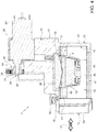
- tubular appendages 36 have respective ends 37 which, when the capsule 2 is fluid-tightly coupled to the cup-shaped gasket 23 ( Figure 4 ), are pressed against the cover 4 and define respective annular seals suitable to prevent any water or beverage that has come out of the hole made by the "operational" needle and on to the cover 4 from entering the tubular appendages 36 and possibly reaching the channels 32.
- the cup-shaped gasket 23 internally houses an abutment element 38 rigidly connected to the frame 10 ( Figure 3 ) and bounded at the bottom by a surface that is rounded towards the bottom, which, when the capsule 2 is pressed against the cup-shaped gasket 23, engages the central portion of the cover 4 and pushes it inwardly into the capsule 2 to such an extent as to stretch said cover 4.
- each end 37 is inclined with respect to the longitudinal axis of the respective tubular appendage 36 at an angle such as to complement the curvature of the cover 4 in the connection area and adhere to the cover 4 in an effective manner.
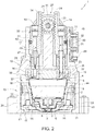
- Figure 2 illustrates the rest position of the needle 26, which is the needle with the larger inside diameter capable of delivering water at a higher flow rate than the needle 27, and the rest position of the needle 27, which is the needle with the smaller inside diameter and delivers a lower flow rate.
- the needles 26 and 27 may be arranged, according to their length, completely inside the respective channels 32 (as is the case of the needle 27 in the example that is illustrated) or protrude from the respective channel 32 and engage a first section of the respective tubular appendage 36 (as is the case of the needle 26 in the example that is illustrated), but without extending, in any case, beyond the end 37 of said tubular appendage 36.
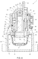
- Figure 5 illustrates the configuration of the needle injection device 24 when the needle 26 is in the extracted operating position and, consequently, the needle 27 is in its retracted waiting position.
- needles like the needle 26, which supply a high flow rate and at low speed are used for capsules 2 designed to produce beverages that have to be extracted at low pressure, for example infusions or Americano-type coffee; such capsules do not normally have the aforesaid micro-perforated sheet 9.
- needles of this type are normally made to penetrate the capsule 2 relatively deeply so as to inject water directly into the dose of material to be brewed.
- the needle 26 comprises a hollow cylindrical stem, a solid tip cut obliquely, and a water outlet on the side facing the centre of the capsule 2 in order to facilitate the circulation of the water through the material to be brewed.
- Figure 6 illustrates the configuration of the needle injection device 24 when the needle 27 is in the extracted operating position and, consequently, the needle 26 is in the retracted waiting position.
- needles like the needle 27, which supply a low flow rate and at high speed, are used for capsules 2 designed for producing beverages that have to be extracted at high pressure, for example espresso coffee; such capsules are normally provided with the aforesaid micro-perforated sheet 9 which has the function of distributing the water and ensuring that it penetrates the material in a uniform manner.
- the needle 27 comprises a hollow cylindrical stem with a thin tip portion and an axial opening through which the water flows out.
- the time for which the motor 29 is driven and, thus, the length of the displacement of the "operational" needle 26 or 27 from the rest position to the extracted operating position, is controlled by the electronic control unit (not illustrated) on the basis of signals sent to said electronic unit by sensor means designed to detect the axial position of the sliding blocks 31 along the respective guide channels 32.
- said sensor means consist, for example, of a Hall effect sensor 39 (of the conventional type) mounted on the upper portion 13 of the frame 10 and coupled to magnets 40 mounted on the sliding blocks 31.
- the transmission 28 could be different from that illustrated, for example it could consist of a mechanical linkage transmission or a hydraulic transmission.
- the transmission 28 could be configured to move, each time, only the needle selected to perforate the capsule, leaving the other needle stationary in the respective rest position.
- the displacements of the needles 26 and 27 could be controlled on the basis of sensors other than the Hall effect sensor described above, for example by using an encoder coupled to the shaft 30 of the electric motor 29 or a hydraulic system or any other system suitable for the purpose.
- the capsule holder 11 is designed as a drawer able to slide in the direction 17 of insertion/extraction between an extracted loading position, in which a capsule 2 can be loaded into/removed from the cavity 12, and a brewing position, in which the capsule holder 11 is inserted into the seat 16 in the frame 10 and the cavity 12, with the capsule 2 that has been inserted, is arranged underneath and in a position coaxial to the cup-shaped gasket 23.
- the capsule holder 11 is also configured to move the capsule 2 from and towards a fluid-tight coupling position with said cup-shaped gasket 23.
- the transmission device 55 is defined by a cam mechanism housed inside the lower portion 43 and comprising two cams 56, each of which is rigidly connected to a corresponding elongated element 54, at an axial end of the latter opposite to the end to which the handle 53 is connected, and has, along an upper profile thereof, two inclined planes 57 and two horizontal planes 58, each of which is adjacent to the top of a respective inclined plane 57.
- the transmission device 55 further comprises follower means defined, for each cam 56, by a pair of pins 59 rigidly coupled to the upper portion 44 and each coupled to a respective inclined plane 57. The constant contact between the pins 59 and the respective inclined planes 57 is guaranteed by the springs 52 that normally hold the upper portion 44 pushed downwards and towards the lower portion 43.
- the angle of the inclined planes 57 is such that when the handle 53 is moved from the spaced position to the close position, so that the cams 56 slide forward, the pins 59 follow the respective inclined planes 57 upwards from the bottom, thus raising the upper portion 44.
- the pins 59 engage the respective horizontal planes 58 to make the raised position of the upper portion 44 stable.
- the horizontal planes 58 have a slight concavity designed to be engaged by the pins 59 in order to prevent, in use, any stress unintentionally applied to the main body 41, for instance vibrations, from undermining the stability of the raised position of the upper portion 44.
- the capsule 2 comes into contact with the cup-shaped gasket 23 and is pushed into the cavity 12 with the subsequent deformation and perforation of the sealing film 7 by the tip 8.
- the transmission device 55 could have a different architecture from that of the example illustrated in the accompanying figures, and any type of mechanism capable of converting the horizontal displacement of the handle 53 into a vertical displacement of the upper portion 44 of the capsule holder 11 could be used.
Landscapes
- Engineering & Computer Science (AREA)
- Food Science & Technology (AREA)
- Mechanical Engineering (AREA)
- Apparatus For Making Beverages (AREA)
Description
- This application claims priority from Italian Patent Application No.
102016000130874 filed on December 23, 2016 - The present invention relates to a brewing apparatus for preparing a beverage from a single-serve capsule containing a dose of infusible or soluble material, such as coffee, tea, chocolate, milk, etc.
- In particular, the present invention can advantageously be applied to a brewing apparatus of the type comprising a supply apparatus to supply a brewing fluid, normally pressurized hot water, into the capsule, and a capsule holder, which is provided with a seat to receive a capsule and is mounted so as to slide, in a substantially horizontal direction, to allow a capsule to be loaded and to enable said capsule to be moved to a brewing position, in which the capsule faces an outlet of the brewing fluid supply apparatus.
- In use, when the capsule-holder has been moved to the aforesaid brewing position, the outlet of the brewing fluid supply apparatus must be fluid-tightly coupled to the part of capsule through which the brewing fluid must be supplied.
- For that purpose, the brewing apparatus is generally provided with actuators designed to move the capsule-holder and the injection unit with respect to one another, from and towards the necessary coupling position.
- Various solutions for actuators having such function have been developed in the prior art; an example of a prior art solution are actuators of the manual type based on mechanical linkage systems operated directly by the user and configured to move the brewing fluid supply apparatus with respect to the capsule-holder or vice versa; actuators of the automatic type, often hydraulic actuators, connected to the brewing fluid supply apparatus or to the capsule-holder or to both are also known in the prior art.
- A hydraulic actuator designed to move the injection unit towards the capsule-holder in the coupling position is disclosed, for example, in
WO 2010/113019 A1 which describes a percolator assembly for making a beverage from an anhydrous powdered material in a container, wherein the percolator assembly has a seat which is designed to receive the container and is movable in a horizontal direction between a loading position to load the container and a percolating position, in which the seat is aligned with dispensing means for dispensing pressurized hot water. In use, the hydraulic actuator moves the dispensing means downwards to a position in which it forms a fluid-tight connection with the seat, which is moved vertically, pushed by the dispensing means and against the action of springs, from a raised position to a lowered position. - Such solutions, while generally effective, frequently have the drawback of making the brewing apparatus more complex both from a structural perspective and in terms of its architecture and operation, with the negative consequence of increasing the costs and reducing the reliability of said brewing apparatus. Document
WO-A1-2010/113019 shows a brewing apparatus according to the preamble of claim 1. - The purpose of the present invention is to provide a brewing apparatus provided with a capsule-holder of the type described above, said capsule-holder being a simple and economical alternative to the known solutions mentioned above.
- According to the present invention there is provided a beverage brewing apparatus according to that claimed in claim 1 and, preferably, according to that claimed in any one of the subsequent claims depending directly or independently on claim 1.
- The invention will now be described with reference to the accompanying drawings, illustrating a non-limiting embodiment thereof, in which:
-
Figure 1 is a perspective view of a preferred embodiment of the brewing apparatus according to the present invention; -
Figure 2 is a front cross-sectional view of the brewing apparatus ofFigure 1 in a first operating configuration; -
Figure 3 is a side and partially cross-sectional view of the brewing apparatus ofFigure 1 ; -
Figure 4 illustrates the brewing apparatus ofFigure 3 in a different operating configuration; -
Figures 5 and6 illustrate the brewing apparatus ofFigure 2 in two further different operating configurations; -
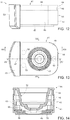
Figure 7 is a side elevation view of a detail of the apparatus ofFigure 1 ; -
Figure 8 is a plan view of the detail ofFigure 7 ; -
Figure 9 is a cross section, along the plane IX-IX, ofFigure 8 ; -
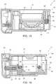
Figure 10 is a cross section, along the plane X-X, ofFigure 8 ; -
Figure 11 is a cross section, along the plane XI-XI, ofFigure 8 ; -
Figure 12 illustrates the detail ofFigure 7 in a different operating configuration; -
Figure 13 illustrates the detail ofFigure 8 in a different operating configuration; -
Figure 14 is a cross section, along the plane IVX-IVX, ofFigure 13 ; -
Figure 15 is a cross section, along the plane XV-XV, ofFigure 13 ; and -
Figure 16 is a cross section, along the plane XVI-XVI, ofFigure 13 . - In
Figure 1 , denoted as a whole by reference numeral 1 is a brewing apparatus suitable for use in an automatic machine for producing beverages by injecting a brewing fluid, typically pressurized hot water, into single-serve capsules containing a dose of infusible or soluble material, for example coffee, tea, chocolate, milk, etc. - In particular, the brewing apparatus 1 is structured to implement the automatic brewing process starting from
capsules 2 of the (known) type comprising a container designed to be perforated, in use, by perforating means borne by the brewing apparatus 1 to permit the injection of the brewing fluid into saidcapsule 2. - As will become more apparent from the following description, the brewing apparatus 1 is configured to permit the use, in the same automatic machine, of
capsules 2 that are identical to one another as far as their geometry and outside dimensions are concerned, but differ for the material they contain in terms of form, compactness and quantity, and for their internal structure. - Purely by way of example, the accompanying figures illustrate a
capsule 2 of the type described above, which comprises a cup-shaped body with abeverage outflow aperture 3 at the bottom, and acover 4, which is seal-welded to anannular flange 5 on the outside of the cup-shaped body and consists of a perforable membrane, preferably obtained from a single or multi-layer sheet of plastic and/or metal material. - The cup-shaped body is made of a waterproof plastic material, preferably obtained by thermoforming a material with oxygen and moisture barrier properties such as PP-EVOH-PP, for example, or by means of injection moulding with Polypropylene (PP) or Polybutylene terephthalate (PBT), and houses a
filtering element 6, which divides the inside of thecapsule 2 into an upper chamber containing the infusible material and a lower chamber communicating with thebeverage outflow aperture 3. Thecapsule 2 is further provided with a sealing film 7 connected to an inside surface of the cup-shaped body to seal theoutflow aperture 3 and which is designed to be perforated, following an axial compression of thecapsule 2 and the subsequent collapsing of the cup-shaped body, by atip 8 borne by thefiltering element 6. - According to the above description, the
capsule 2 may be produced, as known in the prior art, in different versions depending on the type of beverage it is to produce. The different versions of thecapsule 2 differ for the addition or absence of certain components inside thecapsule 2 and, in general, can be grouped into two categories according to the type of brewing process required to obtain the respective beverages. - A first category comprises capsules that require a high-pressure brewing process, in which the injection fluid is fed into said capsule at a relatively low flow rate and relatively high speed. Capsules of this type are used, for example, to produce espresso coffee or soluble beverages.
- A second category comprises capsules that require a low-pressure brewing process, in which the injection fluid is fed into said capsule at a relatively high flow rate and relatively low speed. Capsules of this type are used, for example, to produce so-called "Americano" coffee, or tea and other infusions.
- With reference to the
capsule 2 illustrated in the accompanying figures, the inside structure may vary according to the beverage that thecapsule 2 is to produce. - For example, the openings in the
filtering element 6 may have different shapes and sizes; there may be a barrier element consisting of one or more superimposed membranes, possibly pre-cut, welded to the lower surface of thefiltering element 6 to improve the pre-brewing of the material; the sealing film 7 may be missing or may be replaced with a manually removable external film. Furthermore, for capsules designed for high-pressure brewing, thecapsule 2 may comprise (Figure 6 ) amicro-perforated sheet 9 arranged in the upper chamber at a certain distance from thecover 5 to define an empty space between the material and thecover 4 and, in use, aid the uniform distribution of the brewing fluid. - With reference to
Figures 1 and2 , the brewing apparatus 1 comprises aframe 10, designed to be fixed to the inside of a casing (not illustrated) of the automatic machine, and acapsule holder 11 provided with acavity 12 configured to receive acapsule 2. - The
frame 10 comprises anupper portion 13, which supports awater injection unit 14, and alower portion 15, which defines aseat 16 suitable to be removably engaged by thecapsule holder 11 to support it in a brewing position under theinjection unit 14. - According to that illustrated in
Figure 1 , thecapsule holder 11, which will be described in detail later on in this document, is designed as a drawer able to slide in adirection 17 of insertion/extraction (indicated by a double arrow inFigure 1 ) between an extracted loading position, in which thecapsule holder 11 is outside theseat 16 to allow a user to remove anempty capsule 2 from thecavity 12 and load a new capsule 2 (Figure 1 ), and said brewing position, in which thecapsule holder 11 is fully inserted into the seat 16 (Figure 4 ). In the preferred embodiment that is illustrated, thecapsule holder 11 can be detached from theframe 10. According to an alternative embodiment, thecapsule holder 11 may only be partially extracted from theseat 16 provided this is sufficient to allow the user to access thecavity 12 to load or remove acapsule 2. - With reference to
Figures 1 ,2 and3 , theseat 16 has anentrance 18 and is defined by a substantially horizontalupper wall 19 and by two substantiallyvertical side walls 20, parallel to one another and to thedirection 17 and provided with respectivelower edges 21, which are bent towards one another and towards the inside of theseat 16 so as to define, with therespective side walls 20, a straight guide suitable to be engaged in a sliding manner by thecapsule holder 11 in thedirection 17. - At the end opposite to the
entrance 18, theseat 16 is bounded by a transverse wall 22 (Figure 3 ), which joins theside walls 20 to one another and defines a stop member to stop thecapsule holder 11, when the latter is inserted into theseat 16, in a given position with respect to theinjection unit 14, that is to say, in said brewing position. - According to that illustrated in
Figures 1 and2 , when thecapsule holder 11 is arranged in the brewing position, thecavity 12 in thecapsule holder 11 faces a cup-shaped gasket 23, which is firmly inserted in a cavity provided in theupper wall 19, with its concave side facing downwards, and has an annular end lip designed to couple, in use, with thecover 4 of acapsule 2, roughly at therespective flange 5, to define a radial seal around a central area of thecover 4 to be perforated to allow the pressurized hot water to be fed into thecapsule 2. - For that purpose, the
injection unit 14 comprises aneedle injection device 24, anactuator device 25 to operate theneedle injection device 24, and a pump (not illustrated) to supply water at a given pressure to theneedle injection device 24. - The
needle injection device 24 comprises a pair ofhollow needles upper portion 13 of theframe 10 above the cup-shaped gasket 23 and each of which is movable in a vertical direction between a respective normal rest position, in which the needle is retracted and does not protrude beyond the cup-shaped gasket 23, and a respective operating position, in which the needle is in a forward position and protrudes beyond the cup-shaped gasket 23 in order to penetrate thecover 4 of acapsule 2 arranged in thecapsule holder 11 in the brewing position to inject the pressurized hot water into saidcapsule 2. - The
needles capsule 2 to be processed. - For that purpose, the
needles actuator device 25 by means of atransmission 28 configured so as to make only one of the twoneedles - According to the preferred embodiment illustrated in the accompanying figures, the
transmission 28 is a mechanical transmission and theactuator device 25 that operates it comprises anelectric motor 29 connected to an electronic control unit (not illustrated) and has apower output shaft 30 able to rotate about an axis parallel to thedirection 17. - With particular reference to
Figures 1 ,2 ,5 and7 , thetransmission 28 comprises twosliding blocks 31, each of which carries arespective needle respective guide channel 32 obtained in theupper portion 13 of theframe 10 and open towards theseat 16. - Each sliding
block 31 has anaxial duct 33, which comprises a widened upper portion, suitable to be engaged by a connection (not illustrated) for coupling to a delivery pipe of the water pump (not illustrated), and a widened lower position engaged, preferably in a detachable manner, by an axial end of therespective needle - The two sliding
blocks 31 are arranged on opposite sides of theshaft 30 of themotor 29 and comprise respective toothed flat upper portions, which definerespective racks 34 facing and parallel to one another and both meshing with apinion 35 splined to theshaft 30 and which is part of thetransmission 28. - Thus, the
needles transmission 28 and the displacement of one of the two corresponds to a simultaneous displacement of the other of the same magnitude and in the opposite direction. In practice, while the "operational" needle is moved from the normal rest position to the operating position, the other needle is moved from the normal rest position to a retracted waiting position by performing an equal and opposite displacement with respect to that of the "operational" needle. - According to that illustrated in
Figure 2 , eachneedle tubular appendix 36 of the cup-shapedgasket 23, said appendix extending downwards, from a bottom wall of the cup-shapedgasket 23, up to, and preferably slightly beyond, the annular end lip of said cup-shapedgasket 23. Eachtubular appendix 36 is suitable to be slidingly engaged by therespective needle - Lastly, the
tubular appendages 36 have respective ends 37 which, when thecapsule 2 is fluid-tightly coupled to the cup-shaped gasket 23 (Figure 4 ), are pressed against thecover 4 and define respective annular seals suitable to prevent any water or beverage that has come out of the hole made by the "operational" needle and on to thecover 4 from entering thetubular appendages 36 and possibly reaching thechannels 32. - To that end, to facilitate the adherence of the
ends 37 of thetubular appendages 36 to thecover 4, the cup-shapedgasket 23 internally houses anabutment element 38 rigidly connected to the frame 10 (Figure 3 ) and bounded at the bottom by a surface that is rounded towards the bottom, which, when thecapsule 2 is pressed against the cup-shapedgasket 23, engages the central portion of thecover 4 and pushes it inwardly into thecapsule 2 to such an extent as to stretch saidcover 4. Preferably, to further improve the fluid-tight coupling between theend 37 and thecover 4, the end surface of eachend 37 is inclined with respect to the longitudinal axis of the respectivetubular appendage 36 at an angle such as to complement the curvature of thecover 4 in the connection area and adhere to thecover 4 in an effective manner. -
Figure 2 illustrates the rest position of theneedle 26, which is the needle with the larger inside diameter capable of delivering water at a higher flow rate than theneedle 27, and the rest position of theneedle 27, which is the needle with the smaller inside diameter and delivers a lower flow rate. In their normal rest positions, theneedles needle 27 in the example that is illustrated) or protrude from therespective channel 32 and engage a first section of the respective tubular appendage 36 (as is the case of theneedle 26 in the example that is illustrated), but without extending, in any case, beyond theend 37 of saidtubular appendage 36. -
Figure 5 illustrates the configuration of theneedle injection device 24 when theneedle 26 is in the extracted operating position and, consequently, theneedle 27 is in its retracted waiting position. Normally, needles like theneedle 26, which supply a high flow rate and at low speed, are used forcapsules 2 designed to produce beverages that have to be extracted at low pressure, for example infusions or Americano-type coffee; such capsules do not normally have the aforesaidmicro-perforated sheet 9. In order to improve the penetration of the water into the material, needles of this type are normally made to penetrate thecapsule 2 relatively deeply so as to inject water directly into the dose of material to be brewed. In the preferred embodiment that is illustrated, theneedle 26 comprises a hollow cylindrical stem, a solid tip cut obliquely, and a water outlet on the side facing the centre of thecapsule 2 in order to facilitate the circulation of the water through the material to be brewed. -
Figure 6 illustrates the configuration of theneedle injection device 24 when theneedle 27 is in the extracted operating position and, consequently, theneedle 26 is in the retracted waiting position. Normally, needles like theneedle 27, which supply a low flow rate and at high speed, are used forcapsules 2 designed for producing beverages that have to be extracted at high pressure, for example espresso coffee; such capsules are normally provided with the aforesaidmicro-perforated sheet 9 which has the function of distributing the water and ensuring that it penetrates the material in a uniform manner. In such cases, after perforating thecover 4, the needle does not penetrate the material directly, but remains between thecover 4 and themicro-perforated sheet 9. In the preferred embodiment that is illustrated, theneedle 27 comprises a hollow cylindrical stem with a thin tip portion and an axial opening through which the water flows out. - In use, the selective activation of the
needles capsule 2 inserted by a user, that is, according to the type of beverage to be produced, drives themotor 29 in one direction or the other in order to bring one of the two needles to perforate thecapsule 2. - The time for which the
motor 29 is driven and, thus, the length of the displacement of the "operational"needle blocks 31 along therespective guide channels 32. In the preferred embodiment that is illustrated, said sensor means consist, for example, of a Hall effect sensor 39 (of the conventional type) mounted on theupper portion 13 of theframe 10 and coupled tomagnets 40 mounted on the sliding blocks 31. - With regard to the above description, it is worth pointing out that, according to alternative embodiments that are not illustrated, the
transmission 28 could be different from that illustrated, for example it could consist of a mechanical linkage transmission or a hydraulic transmission. In particular, according to an alternative embodiment that is not illustrated, thetransmission 28 could be configured to move, each time, only the needle selected to perforate the capsule, leaving the other needle stationary in the respective rest position. Likewise, according to alternative embodiments that are not illustrated, the displacements of theneedles shaft 30 of theelectric motor 29 or a hydraulic system or any other system suitable for the purpose. - The structure and the functioning of the
capsule holder 11, which constitutes a further aspect of the present invention, and is separate from theinjection unit 14, will now be described in detail. - As already mentioned above, the
capsule holder 11 is designed as a drawer able to slide in thedirection 17 of insertion/extraction between an extracted loading position, in which acapsule 2 can be loaded into/removed from thecavity 12, and a brewing position, in which thecapsule holder 11 is inserted into theseat 16 in theframe 10 and thecavity 12, with thecapsule 2 that has been inserted, is arranged underneath and in a position coaxial to the cup-shapedgasket 23. - In addition to the function described above of bearing and supporting the
capsule 2 in a position facing the cup-shapedgasket 23, thecapsule holder 11 is also configured to move thecapsule 2 from and towards a fluid-tight coupling position with said cup-shapedgasket 23. - In particular, according to that illustrated in
Figures 7 to 15 , thecapsule holder 11 comprises amain body 41, which has alongitudinal axis 42 that is parallel to thedirection 17 of insertion/extraction when thecapsule holder 11 is inserted into theseat 16, and comprises alower portion 43 and anupper portion 44, which engages the top of thelower portion 43, is provided with thecavity 12 and is slidingly coupled to thelower portion 43 so as to move, with respect to saidlower portion 43, in a vertical direction between a lowered position, in which thecavity 12 is arranged inside the lower portion 43 (Figures 9 and10 ) and a raised position, in which the cavity is partially extracted from the lower portion 43 (Figures 14 and15 ) . - According to the preferred embodiment of the example that is illustrated, the
lower portion 43 is generally cup shaped and comprises abottom wall 45 and a side wall comprising, in turn, twolongitudinal walls 46 arranged on opposite sides of theaxis 42 and twotransverse walls 47 perpendicular to thelongitudinal walls 46. Theupper portion 44, on the other hand, comprises anupper wall 48, which has a generically rectangular shape, has a sunken central part open at the bottom and defining thecavity 12, and is provided, along its periphery, with anannular edge 49 that extends downwards perpendicularly to theupper wall 48 and slidingly engages an inside surface of the side wall of thelower portion 43. - According to that illustrated in
Figures 8 ,10 and15 , theupper portion 44 is guided vertically onto thelower portion 43 by means of threepins 50 borne by theupper portion 44 and slidingly engaged incorresponding sleeves 51 rigidly coupled to thelower portion 43. Moreover, theupper portion 44 is normally held in said lowered position by elastic means defined by three coil springs 52 (only one of which is visible inFigures 10 and15 ), each of which is wound about arespective pin 50 and is interposed between one end of saidpin 50 and therespective sleeve 51 in order to normally keep theupper portion 44 in the lowered position in contact with thelower portion 43 and to be compressed when theupper portion 44 is raised with respect to thelower portion 43. - According to that illustrated in
Figures 11 and16 , thecapsule holder 11 further comprises ahandle 53 connected to themain body 41 by means of twoelongated elements 54, which are rigidly coupled to thehandle 53, are parallel to theaxis 42 and arranged on opposite sides of saidaxis 42, and engage in an axially sliding manner respective openings obtained through atransverse wall 47 of thelower portion 43 so as to allow thehandle 53 to slide between a position at a distance from the main body 41 (Figures 7 and 8 ) and a position close to the main body 41 (Figures 12 and 13 ) . - The movement of the
handle 53 with respect to themain body 41 determines the activation of atransmission device 55 designed to convert the horizontal rectilinear displacement of thehandle 53 between the spaced position and the close position into a vertical rectilinear displacement of theupper portion 44 between the aforesaid lowered position and raised position. - In particular, according to the preferred embodiment that is illustrated in the accompanying figures, the
transmission device 55 is defined by a cam mechanism housed inside thelower portion 43 and comprising twocams 56, each of which is rigidly connected to a correspondingelongated element 54, at an axial end of the latter opposite to the end to which thehandle 53 is connected, and has, along an upper profile thereof, twoinclined planes 57 and twohorizontal planes 58, each of which is adjacent to the top of a respectiveinclined plane 57. Thetransmission device 55 further comprises follower means defined, for eachcam 56, by a pair ofpins 59 rigidly coupled to theupper portion 44 and each coupled to a respectiveinclined plane 57. The constant contact between thepins 59 and the respectiveinclined planes 57 is guaranteed by thesprings 52 that normally hold theupper portion 44 pushed downwards and towards thelower portion 43. - The angle of the
inclined planes 57 is such that when thehandle 53 is moved from the spaced position to the close position, so that thecams 56 slide forward, thepins 59 follow the respectiveinclined planes 57 upwards from the bottom, thus raising theupper portion 44. Just before thehandle 53 reaches the close position, thepins 59 engage the respectivehorizontal planes 58 to make the raised position of theupper portion 44 stable. Preferably, thehorizontal planes 58 have a slight concavity designed to be engaged by thepins 59 in order to prevent, in use, any stress unintentionally applied to themain body 41, for instance vibrations, from undermining the stability of the raised position of theupper portion 44. - In use, once a
capsule 2 has been loaded into the cavity 12 (Figure 1 ), thecapsule holder 11 is inserted into theseat 16 in thedirection 17. In this configuration, thehandle 53 is in its spaced position and theupper portion 44 is in its lowered position. The pushing force applied by the user to thecapsule holder 11 via thehandle 53 does not determine any displacement of thehandle 53 with respect to themain body 41 in that the horizontal pushing force applied by thecams 56, rigidly coupled to thehandle 53, to thepins 59 is not sufficient to overcome the resistance of thesprings 52 which, through theupper portion 44, keep thepins 59 pushed downwards. Therefore the pushing force applied by the user only causes thecapsule holder 11 to move forward without any relative displacement between thehandle 53 and themain body 41. - When the
capsule holder 11 reaches the bottom of theseat 16 and comes into contact with thetransverse wall 22 of the seat 16 (Figure 3 ), themain body 41 cannot move any further forward and a further pushing force applied by the user to thehandle 53 causes thehandle 53 to move forward towards its close position. The displacement of thehandle 53 causes thecams 56 to slide forward and the subsequent raising of theupper portion 44, in the way that is described above. - When the
upper portion 44 has almost reached the raised position, thecapsule 2 comes into contact with the cup-shapedgasket 23 and is pushed into thecavity 12 with the subsequent deformation and perforation of the sealing film 7 by thetip 8. - When the
upper portion 44 reaches the raised position (Figure 4 ), theupper wall 48 of theupper portion 44 presses theflange 5 of thecapsule 2 against theupper wall 19 of theseat 16, and the annular lip of the cup-shapedgasket 23 and thetubular appendages 36 are fluid-tightly pressed against thecover 4, stretched by theabutment element 38. - When the
handle 53 reaches the close position this is detected by aposition sensor 60 mounted on theframe 10 and connected to the electronic control unit (not illustrated), which then starts themotor 29 with the subsequent perforation of thecover 4 of thecapsule 2 by means of one of the twoneedles sensor 60 is a Hall effect sensor coupled to amagnet 61 arranged on thehandle 53. - When the user extracts the
capsule holder 11 from theseat 16, the traction exerted on thehandle 53 first determines a displacement of thehandle 53 with respect to thelower portion 43 and the return of the upper portion to the lowered position due to the returning action of thesprings 52. Once theupper portion 44 has reached the lowered position, the traction exerted on thehandle 53 is rigidly transmitted to thelower portion 43 and determines the extraction of thecapsule holder 11 until it reaches the loading position. - With regard to the above description, it is worth pointing out that, according to alternative embodiments that are not illustrated, the
transmission device 55 could have a different architecture from that of the example illustrated in the accompanying figures, and any type of mechanism capable of converting the horizontal displacement of thehandle 53 into a vertical displacement of theupper portion 44 of thecapsule holder 11 could be used.
Claims (8)
- A beverage brewing apparatus (1) to prepare a beverage from a single-serve capsule (2) containing a dose of infusible or soluble material; the beverage brewing apparatus (1) comprises a capsule holder (11) with a capsule seat (12) to receive a capsule (2) in a brewing position, and a brewing fluid supply apparatus (14) to supply a brewing fluid into a capsule (2) in the brewing position; the capsule holder (11) is designed as a drawer and is mounted to slide in an insertion/extraction direction (17) to allow a capsule (2) to be received and moved to the brewing position, where the capsule (2) faces an outlet (23) of the brewing fluid supply apparatus (14); the capsule holder (11) comprises a main body (41) to support the capsule (2) and having a lower portion (43) and an upper portion (44) provided with the capsule seat (12) and slidingly mounted on the lower portion (43) to move, with respect thereto, to and from a raised position, characterized in that in the raised position the capsule (2) is fluid-tightly coupled to the outlet of the brewing fluid supply apparatus (14).
- The beverage brewing apparatus (1) of claim 1, further comprising a seat (16) suitable to be slidingly engaged by the capsule-holder (11) during insertion/extraction of the capsule-holder (11); the seat (16) having a stop member (47) to limit insertion of the capsule-holder (11) in the seat (16); the lower and upper portions (43, 44) are slidingly coupled to each other to cause, during insertion of the capsule-holder (11), the upper portion (44) to remain stationary with respect to the lower portion (43), and when the lower portion (43) reaches the stop member (47), the upper portion (44) to slide with respect to the lower portion (43) until the raised position is reached.
- The beverage brewing apparatus (1) of claim 2, wherein the capsule-holder (11) comprises retaining and return means (52) between the lower and upper portions (43, 44) to cause the lower and upper portions (43, 44) to move together during insertion of the capsule-holder (11), and to cause the upper portion (44) to slide with respect to the lower portion (43) when the lower portion (43) reaches the stop member (47).
- The beverage brewing apparatus (1) of claim 2 or 3, comprising a handle (53) coupled to the lower portion (43) to allow the capsule-holder (11) to be manually operated; wherein the upper portion (44) is mounted to slide with respect to the lower portion (43) in a direction perpendicular to the insertion/extraction direction (17) in response to a movement of the handle (53) with respect to the lower portion (43) in the insertion/extraction direction (17) when the lower portion (43) reaches the stop member (47).
- The beverage brewing apparatus (1) of claim 3, wherein the retaining and return means (52) are elastic means.
- The beverage brewing apparatus (1) of claim 4, wherein the capsule-holder (11) comprises a transmission (55) to transform a sliding of the handle (53) with respect to the lower portion (43) in the insertion/extraction direction (17) into a sliding of the upper portion (44) with respect to the lower portion (43) in a direction perpendicular to the insertion/extraction direction (17); the transmission (55) comprises a cam (56) rigidly coupled to the handle (53), and a tappet (59) rigidly coupled to the upper portion (44).
- The beverage brewing apparatus (1) of any one of the preceding claims, wherein the outlet (23) of the brewing fluid supply apparatus (14) comprises a gasket (23), and the brewing fluid supply apparatus (14) comprises two hollow needles (26, 27) selectively movable through the gasket (23) to perforate the capsule (2).
- The beverage brewing apparatus (1) of claim 4, further comprising a position sensor (60) to detect the capsule-holder (11) reaching the stop member (47).
Applications Claiming Priority (2)
| Application Number | Priority Date | Filing Date | Title |
|---|---|---|---|
| IT102016000130874A IT201600130874A1 (en) | 2016-12-23 | 2016-12-23 | PORTA-CAPSULE FOR AN INFUSER GROUP FOR THE PREPARATION OF DRINKS FROM THE DISPOSABLE CAPSULES |
| PCT/IB2017/058367 WO2018116279A1 (en) | 2016-12-23 | 2017-12-22 | Capsule holder for a brewing apparatus for preparing a beverage from a single- serve capsule |
Publications (2)
| Publication Number | Publication Date |
|---|---|
| EP3558074A1 EP3558074A1 (en) | 2019-10-30 |
| EP3558074B1 true EP3558074B1 (en) | 2020-09-16 |
Family
ID=58670221
Family Applications (1)
| Application Number | Title | Priority Date | Filing Date |
|---|---|---|---|
| EP17832568.4A Active EP3558074B1 (en) | 2016-12-23 | 2017-12-22 | Capsule holder for a brewing apparatus for preparing a beverage from a single- serve capsule |
Country Status (3)
| Country | Link |
|---|---|
| EP (1) | EP3558074B1 (en) |
| IT (1) | IT201600130874A1 (en) |
| WO (1) | WO2018116279A1 (en) |
Families Citing this family (5)
| Publication number | Priority date | Publication date | Assignee | Title |
|---|---|---|---|---|
| CN109381022A (en) * | 2018-11-30 | 2019-02-26 | 深圳市朗科智能电气股份有限公司 | Auto extractive capsule coffee machine |
| IT201900005462A1 (en) | 2019-04-09 | 2020-10-09 | Gruppo Gimoka S R L | INFUSER GROUP FOR THE PREPARATION OF BEVERAGES STARTING FROM DISPOSABLE CAPSULES |
| EP4147612A1 (en) * | 2021-09-10 | 2023-03-15 | Delica AG | Brewing unit, beverage preparation machine and beverage preparation system |
| EP4147610A1 (en) * | 2021-09-10 | 2023-03-15 | Delica AG | Beverage preparation system and brewing chamber section, brewing unit, beverage preparation machine, and method for ejecting a capsule: |
| EP4147611A1 (en) * | 2021-09-10 | 2023-03-15 | Delica AG | Beverage preparation machine and method and system for beverage preparation |
Family Cites Families (3)
| Publication number | Priority date | Publication date | Assignee | Title |
|---|---|---|---|---|
| DE60126161D1 (en) * | 2000-11-07 | 2007-03-08 | Smile Coffee S R L | Beverage dispenser |
| DE202004020913U1 (en) * | 2004-01-30 | 2006-04-13 | BSH Bosch und Siemens Hausgeräte GmbH | Coffee machine has a drawer for coffee pads which is inserted into machine, lever allowing coffee pad holder to be moved up and down with respect to brewing chamber lid to open and close chamber |
| ITTO20090252A1 (en) * | 2009-04-01 | 2010-10-02 | Sgl Italia S R L Con Unico Socio | PERCOLATOR GROUP FOR THE PRODUCTION OF A BEVERAGE |
-
2016
- 2016-12-23 IT IT102016000130874A patent/IT201600130874A1/en unknown
-
2017
- 2017-12-22 EP EP17832568.4A patent/EP3558074B1/en active Active
- 2017-12-22 WO PCT/IB2017/058367 patent/WO2018116279A1/en unknown
Also Published As
| Publication number | Publication date |
|---|---|
| IT201600130874A1 (en) | 2018-06-23 |
| WO2018116279A1 (en) | 2018-06-28 |
| EP3558074A1 (en) | 2019-10-30 |
Similar Documents
| Publication | Publication Date | Title |
|---|---|---|
| EP3558078B1 (en) | Brewing apparatus for preparing a beverage from a single-serve capsule | |
| EP3558074B1 (en) | Capsule holder for a brewing apparatus for preparing a beverage from a single- serve capsule | |
| EP2033551B1 (en) | Capsule piercing module | |
| US9186018B2 (en) | Dispensing assembly for machines for the preparation of beverages using capsules | |
| EP1900653B1 (en) | Sealed capsule for making a beverage | |
| JP6080849B2 (en) | Extraction system cartridge chamber | |
| JP6223339B2 (en) | Cartridge alignment system | |
| CA2800862C (en) | Brewing device for extracting a portion capsule, method for operating a brewing device and use of a brewing device | |
| US9119504B2 (en) | Delivery assembly for machines for preparing liquid products via cartridges | |
| US9456716B2 (en) | Beverage preparation machine with automatic cleaning system | |
| EP1453405B1 (en) | Beverage brewing method and apparatus | |
| EP2747608B1 (en) | Long-lasting cartridge piercer | |
| EP2218370A2 (en) | Beverage brewing unit | |
| CN102686133A (en) | Infusion device for infusion capsules and the like, particularly for espresso coffee machines and the like | |
| AU2008212121A1 (en) | Infusion device to prepare beverages from single-serving capsules with capsule centering device | |
| CN108601474B (en) | System for preparing a beverage using a capsule | |
| CN103764001A (en) | Cartridge removal system | |
| WO2015162468A1 (en) | Apparatus and method for making a beverage using a powdered food substance contained in a capsule |
Legal Events
| Date | Code | Title | Description |
|---|---|---|---|
| STAA | Information on the status of an ep patent application or granted ep patent |
Free format text: STATUS: UNKNOWN |
|
| STAA | Information on the status of an ep patent application or granted ep patent |
Free format text: STATUS: THE INTERNATIONAL PUBLICATION HAS BEEN MADE |
|
| PUAI | Public reference made under article 153(3) epc to a published international application that has entered the european phase |
Free format text: ORIGINAL CODE: 0009012 |
|
| STAA | Information on the status of an ep patent application or granted ep patent |
Free format text: STATUS: REQUEST FOR EXAMINATION WAS MADE |
|
| 17P | Request for examination filed |
Effective date: 20190610 |
|
| AK | Designated contracting states |
Kind code of ref document: A1 Designated state(s): AL AT BE BG CH CY CZ DE DK EE ES FI FR GB GR HR HU IE IS IT LI LT LU LV MC MK MT NL NO PL PT RO RS SE SI SK SM TR |
|
| AX | Request for extension of the european patent |
Extension state: BA ME |
|
| DAV | Request for validation of the european patent (deleted) | ||
| DAX | Request for extension of the european patent (deleted) | ||
| GRAP | Despatch of communication of intention to grant a patent |
Free format text: ORIGINAL CODE: EPIDOSNIGR1 |
|
| STAA | Information on the status of an ep patent application or granted ep patent |
Free format text: STATUS: GRANT OF PATENT IS INTENDED |
|
| INTG | Intention to grant announced |
Effective date: 20200408 |
|
| GRAS | Grant fee paid |
Free format text: ORIGINAL CODE: EPIDOSNIGR3 |
|
| GRAA | (expected) grant |
Free format text: ORIGINAL CODE: 0009210 |
|
| STAA | Information on the status of an ep patent application or granted ep patent |
Free format text: STATUS: THE PATENT HAS BEEN GRANTED |
|
| AK | Designated contracting states |
Kind code of ref document: B1 Designated state(s): AL AT BE BG CH CY CZ DE DK EE ES FI FR GB GR HR HU IE IS IT LI LT LU LV MC MK MT NL NO PL PT RO RS SE SI SK SM TR |
|
| REG | Reference to a national code |
Ref country code: GB Ref legal event code: FG4D |
|
| REG | Reference to a national code |
Ref country code: CH Ref legal event code: EP |
|
| REG | Reference to a national code |
Ref country code: DE Ref legal event code: R096 Ref document number: 602017023909 Country of ref document: DE |
|
| REG | Reference to a national code |
Ref country code: IE Ref legal event code: FG4D |
|
| REG | Reference to a national code |
Ref country code: AT Ref legal event code: REF Ref document number: 1313354 Country of ref document: AT Kind code of ref document: T Effective date: 20201015 |
|
| PG25 | Lapsed in a contracting state [announced via postgrant information from national office to epo] |
Ref country code: HR Free format text: LAPSE BECAUSE OF FAILURE TO SUBMIT A TRANSLATION OF THE DESCRIPTION OR TO PAY THE FEE WITHIN THE PRESCRIBED TIME-LIMIT Effective date: 20200916 Ref country code: NO Free format text: LAPSE BECAUSE OF FAILURE TO SUBMIT A TRANSLATION OF THE DESCRIPTION OR TO PAY THE FEE WITHIN THE PRESCRIBED TIME-LIMIT Effective date: 20201216 Ref country code: GR Free format text: LAPSE BECAUSE OF FAILURE TO SUBMIT A TRANSLATION OF THE DESCRIPTION OR TO PAY THE FEE WITHIN THE PRESCRIBED TIME-LIMIT Effective date: 20201217 Ref country code: SE Free format text: LAPSE BECAUSE OF FAILURE TO SUBMIT A TRANSLATION OF THE DESCRIPTION OR TO PAY THE FEE WITHIN THE PRESCRIBED TIME-LIMIT Effective date: 20200916 Ref country code: FI Free format text: LAPSE BECAUSE OF FAILURE TO SUBMIT A TRANSLATION OF THE DESCRIPTION OR TO PAY THE FEE WITHIN THE PRESCRIBED TIME-LIMIT Effective date: 20200916 Ref country code: BG Free format text: LAPSE BECAUSE OF FAILURE TO SUBMIT A TRANSLATION OF THE DESCRIPTION OR TO PAY THE FEE WITHIN THE PRESCRIBED TIME-LIMIT Effective date: 20201216 |
|
| REG | Reference to a national code |
Ref country code: AT Ref legal event code: MK05 Ref document number: 1313354 Country of ref document: AT Kind code of ref document: T Effective date: 20200916 |
|
| REG | Reference to a national code |
Ref country code: NL Ref legal event code: MP Effective date: 20200916 |
|
| PG25 | Lapsed in a contracting state [announced via postgrant information from national office to epo] |
Ref country code: LV Free format text: LAPSE BECAUSE OF FAILURE TO SUBMIT A TRANSLATION OF THE DESCRIPTION OR TO PAY THE FEE WITHIN THE PRESCRIBED TIME-LIMIT Effective date: 20200916 Ref country code: RS Free format text: LAPSE BECAUSE OF FAILURE TO SUBMIT A TRANSLATION OF THE DESCRIPTION OR TO PAY THE FEE WITHIN THE PRESCRIBED TIME-LIMIT Effective date: 20200916 |
|
| REG | Reference to a national code |
Ref country code: LT Ref legal event code: MG4D |
|
| PG25 | Lapsed in a contracting state [announced via postgrant information from national office to epo] |
Ref country code: EE Free format text: LAPSE BECAUSE OF FAILURE TO SUBMIT A TRANSLATION OF THE DESCRIPTION OR TO PAY THE FEE WITHIN THE PRESCRIBED TIME-LIMIT Effective date: 20200916 Ref country code: RO Free format text: LAPSE BECAUSE OF FAILURE TO SUBMIT A TRANSLATION OF THE DESCRIPTION OR TO PAY THE FEE WITHIN THE PRESCRIBED TIME-LIMIT Effective date: 20200916 Ref country code: PT Free format text: LAPSE BECAUSE OF FAILURE TO SUBMIT A TRANSLATION OF THE DESCRIPTION OR TO PAY THE FEE WITHIN THE PRESCRIBED TIME-LIMIT Effective date: 20210118 Ref country code: CZ Free format text: LAPSE BECAUSE OF FAILURE TO SUBMIT A TRANSLATION OF THE DESCRIPTION OR TO PAY THE FEE WITHIN THE PRESCRIBED TIME-LIMIT Effective date: 20200916 Ref country code: LT Free format text: LAPSE BECAUSE OF FAILURE TO SUBMIT A TRANSLATION OF THE DESCRIPTION OR TO PAY THE FEE WITHIN THE PRESCRIBED TIME-LIMIT Effective date: 20200916 Ref country code: SM Free format text: LAPSE BECAUSE OF FAILURE TO SUBMIT A TRANSLATION OF THE DESCRIPTION OR TO PAY THE FEE WITHIN THE PRESCRIBED TIME-LIMIT Effective date: 20200916 |
|
| RAP4 | Party data changed (patent owner data changed or rights of a patent transferred) |
Owner name: GRUPPO GIMOKA S.R.L. |
|
| PG25 | Lapsed in a contracting state [announced via postgrant information from national office to epo] |
Ref country code: IS Free format text: LAPSE BECAUSE OF FAILURE TO SUBMIT A TRANSLATION OF THE DESCRIPTION OR TO PAY THE FEE WITHIN THE PRESCRIBED TIME-LIMIT Effective date: 20210116 Ref country code: PL Free format text: LAPSE BECAUSE OF FAILURE TO SUBMIT A TRANSLATION OF THE DESCRIPTION OR TO PAY THE FEE WITHIN THE PRESCRIBED TIME-LIMIT Effective date: 20200916 Ref country code: AL Free format text: LAPSE BECAUSE OF FAILURE TO SUBMIT A TRANSLATION OF THE DESCRIPTION OR TO PAY THE FEE WITHIN THE PRESCRIBED TIME-LIMIT Effective date: 20200916 Ref country code: AT Free format text: LAPSE BECAUSE OF FAILURE TO SUBMIT A TRANSLATION OF THE DESCRIPTION OR TO PAY THE FEE WITHIN THE PRESCRIBED TIME-LIMIT Effective date: 20200916 Ref country code: ES Free format text: LAPSE BECAUSE OF FAILURE TO SUBMIT A TRANSLATION OF THE DESCRIPTION OR TO PAY THE FEE WITHIN THE PRESCRIBED TIME-LIMIT Effective date: 20200916 |
|
| REG | Reference to a national code |
Ref country code: DE Ref legal event code: R097 Ref document number: 602017023909 Country of ref document: DE |
|
| PG25 | Lapsed in a contracting state [announced via postgrant information from national office to epo] |
Ref country code: SK Free format text: LAPSE BECAUSE OF FAILURE TO SUBMIT A TRANSLATION OF THE DESCRIPTION OR TO PAY THE FEE WITHIN THE PRESCRIBED TIME-LIMIT Effective date: 20200916 |
|
| PLBE | No opposition filed within time limit |
Free format text: ORIGINAL CODE: 0009261 |
|
| STAA | Information on the status of an ep patent application or granted ep patent |
Free format text: STATUS: NO OPPOSITION FILED WITHIN TIME LIMIT |
|
| 26N | No opposition filed |
Effective date: 20210617 |
|
| PG25 | Lapsed in a contracting state [announced via postgrant information from national office to epo] |
Ref country code: MC Free format text: LAPSE BECAUSE OF FAILURE TO SUBMIT A TRANSLATION OF THE DESCRIPTION OR TO PAY THE FEE WITHIN THE PRESCRIBED TIME-LIMIT Effective date: 20200916 Ref country code: DK Free format text: LAPSE BECAUSE OF FAILURE TO SUBMIT A TRANSLATION OF THE DESCRIPTION OR TO PAY THE FEE WITHIN THE PRESCRIBED TIME-LIMIT Effective date: 20200916 Ref country code: SI Free format text: LAPSE BECAUSE OF FAILURE TO SUBMIT A TRANSLATION OF THE DESCRIPTION OR TO PAY THE FEE WITHIN THE PRESCRIBED TIME-LIMIT Effective date: 20200916 |
|
| PG25 | Lapsed in a contracting state [announced via postgrant information from national office to epo] |
Ref country code: LU Free format text: LAPSE BECAUSE OF NON-PAYMENT OF DUE FEES Effective date: 20201222 Ref country code: IE Free format text: LAPSE BECAUSE OF NON-PAYMENT OF DUE FEES Effective date: 20201222 |
|
| PG25 | Lapsed in a contracting state [announced via postgrant information from national office to epo] |
Ref country code: TR Free format text: LAPSE BECAUSE OF FAILURE TO SUBMIT A TRANSLATION OF THE DESCRIPTION OR TO PAY THE FEE WITHIN THE PRESCRIBED TIME-LIMIT Effective date: 20200916 Ref country code: MT Free format text: LAPSE BECAUSE OF FAILURE TO SUBMIT A TRANSLATION OF THE DESCRIPTION OR TO PAY THE FEE WITHIN THE PRESCRIBED TIME-LIMIT Effective date: 20200916 Ref country code: CY Free format text: LAPSE BECAUSE OF FAILURE TO SUBMIT A TRANSLATION OF THE DESCRIPTION OR TO PAY THE FEE WITHIN THE PRESCRIBED TIME-LIMIT Effective date: 20200916 |
|
| PG25 | Lapsed in a contracting state [announced via postgrant information from national office to epo] |
Ref country code: MK Free format text: LAPSE BECAUSE OF FAILURE TO SUBMIT A TRANSLATION OF THE DESCRIPTION OR TO PAY THE FEE WITHIN THE PRESCRIBED TIME-LIMIT Effective date: 20200916 |
|
| PG25 | Lapsed in a contracting state [announced via postgrant information from national office to epo] |
Ref country code: NL Free format text: LAPSE BECAUSE OF NON-PAYMENT OF DUE FEES Effective date: 20200923 |
|
| PGFP | Annual fee paid to national office [announced via postgrant information from national office to epo] |
Ref country code: GB Payment date: 20231219 Year of fee payment: 7 |
|
| PGFP | Annual fee paid to national office [announced via postgrant information from national office to epo] |
Ref country code: IT Payment date: 20231117 Year of fee payment: 7 Ref country code: FR Payment date: 20231226 Year of fee payment: 7 |
|
| PGFP | Annual fee paid to national office [announced via postgrant information from national office to epo] |
Ref country code: BE Payment date: 20231226 Year of fee payment: 7 |
|
| PGFP | Annual fee paid to national office [announced via postgrant information from national office to epo] |
Ref country code: DE Payment date: 20231227 Year of fee payment: 7 Ref country code: CH Payment date: 20240101 Year of fee payment: 7 |