EP3557771B1 - Interference suppression method and device, and computer storage medium - Google Patents
Interference suppression method and device, and computer storage medium Download PDFInfo
- Publication number
- EP3557771B1 EP3557771B1 EP17882147.6A EP17882147A EP3557771B1 EP 3557771 B1 EP3557771 B1 EP 3557771B1 EP 17882147 A EP17882147 A EP 17882147A EP 3557771 B1 EP3557771 B1 EP 3557771B1
- Authority
- EP
- European Patent Office
- Prior art keywords
- multipath
- specified user
- autocorrelation
- common signal
- matching
- Prior art date
- Legal status (The legal status is an assumption and is not a legal conclusion. Google has not performed a legal analysis and makes no representation as to the accuracy of the status listed.)
- Active
Links
- 230000001629 suppression Effects 0.000 title claims description 35
- 238000000034 method Methods 0.000 title claims description 33
- 239000011159 matrix material Substances 0.000 claims description 189
- 238000005070 sampling Methods 0.000 claims description 123
- 238000004364 calculation method Methods 0.000 claims description 29
- 238000012545 processing Methods 0.000 claims description 17
- 238000010586 diagram Methods 0.000 description 19
- 239000013598 vector Substances 0.000 description 12
- 238000005516 engineering process Methods 0.000 description 10
- 238000004422 calculation algorithm Methods 0.000 description 7
- 230000001934 delay Effects 0.000 description 5
- 101100037618 Neurospora crassa (strain ATCC 24698 / 74-OR23-1A / CBS 708.71 / DSM 1257 / FGSC 987) ant-1 gene Proteins 0.000 description 4
- 238000004891 communication Methods 0.000 description 4
- 239000013307 optical fiber Substances 0.000 description 4
- 241000209094 Oryza Species 0.000 description 3
- 235000007164 Oryza sativa Nutrition 0.000 description 3
- 230000008878 coupling Effects 0.000 description 3
- 238000010168 coupling process Methods 0.000 description 3
- 238000005859 coupling reaction Methods 0.000 description 3
- 235000009566 rice Nutrition 0.000 description 3
- 230000005540 biological transmission Effects 0.000 description 2
- 238000013507 mapping Methods 0.000 description 2
- 238000007796 conventional method Methods 0.000 description 1
- 230000001419 dependent effect Effects 0.000 description 1
- 238000011161 development Methods 0.000 description 1
- 239000002360 explosive Substances 0.000 description 1
- 230000000737 periodic effect Effects 0.000 description 1
- 238000004088 simulation Methods 0.000 description 1
- 230000002123 temporal effect Effects 0.000 description 1
Images


Classifications
-
- H—ELECTRICITY
- H04—ELECTRIC COMMUNICATION TECHNIQUE
- H04B—TRANSMISSION
- H04B7/00—Radio transmission systems, i.e. using radiation field
- H04B7/02—Diversity systems; Multi-antenna system, i.e. transmission or reception using multiple antennas
- H04B7/04—Diversity systems; Multi-antenna system, i.e. transmission or reception using multiple antennas using two or more spaced independent antennas
- H04B7/08—Diversity systems; Multi-antenna system, i.e. transmission or reception using multiple antennas using two or more spaced independent antennas at the receiving station
- H04B7/0837—Diversity systems; Multi-antenna system, i.e. transmission or reception using multiple antennas using two or more spaced independent antennas at the receiving station using pre-detection combining
- H04B7/0842—Weighted combining
- H04B7/0848—Joint weighting
-
- H—ELECTRICITY
- H04—ELECTRIC COMMUNICATION TECHNIQUE
- H04B—TRANSMISSION
- H04B1/00—Details of transmission systems, not covered by a single one of groups H04B3/00 - H04B13/00; Details of transmission systems not characterised by the medium used for transmission
- H04B1/69—Spread spectrum techniques
- H04B1/707—Spread spectrum techniques using direct sequence modulation
- H04B1/7097—Interference-related aspects
- H04B1/711—Interference-related aspects the interference being multi-path interference
- H04B1/7115—Constructive combining of multi-path signals, i.e. RAKE receivers
-
- H—ELECTRICITY
- H04—ELECTRIC COMMUNICATION TECHNIQUE
- H04B—TRANSMISSION
- H04B7/00—Radio transmission systems, i.e. using radiation field
- H04B7/02—Diversity systems; Multi-antenna system, i.e. transmission or reception using multiple antennas
- H04B7/04—Diversity systems; Multi-antenna system, i.e. transmission or reception using multiple antennas using two or more spaced independent antennas
- H04B7/06—Diversity systems; Multi-antenna system, i.e. transmission or reception using multiple antennas using two or more spaced independent antennas at the transmitting station
- H04B7/0613—Diversity systems; Multi-antenna system, i.e. transmission or reception using multiple antennas using two or more spaced independent antennas at the transmitting station using simultaneous transmission
- H04B7/0615—Diversity systems; Multi-antenna system, i.e. transmission or reception using multiple antennas using two or more spaced independent antennas at the transmitting station using simultaneous transmission of weighted versions of same signal
- H04B7/0617—Diversity systems; Multi-antenna system, i.e. transmission or reception using multiple antennas using two or more spaced independent antennas at the transmitting station using simultaneous transmission of weighted versions of same signal for beam forming
Definitions
- the present invention relates to anti-interference technology in the field of communications and, in particular, an interference suppression method, device and computer storage medium.
- Multi-antenna array technology has been widely used in 3rd generation partnership project (3GPP).
- 3GPP 3rd generation partnership project
- MRC maximal ratio combining
- IRC interference rejection combining
- the IRC technology is a technology of RAKE receiver which is more advanced.
- the RAKE receiver considers both temporal interference and spatial characteristic. Therefore, anti-interference performance is obviously improved, uplink signal quality is significantly improved, and demodulation performance of uplink signal is improved.
- the key to suppress interference with IRC algorithm is to obtain a correlation matrix and a weight vector of interference and noise. Accurate acquisition of correlation characteristics of interference and noise will have great influence on performance of the IRC algorithm. A better gain can be obtained by calculating a correlation matrix of interference and noise for each user and inverting the correlation matrix.
- the RAKE receiver on entire building baseband unit (BBU) needs to handle a large number of users. If the correlation matrix of interference and noise is calculated and inverted for each user, the entire system will have extremely high computational complexity and can hardly be realized.
- WO2013025134 A1 discloses a receiver unit having at least one antenna input for receiving multipath radio signals via a radio unit and at least one antenna from one or more user equipments.
- the receiver unit comprises: a despreading unit configured to despread a multipath radio signal in the received multipath radio signals using a number of despreading fingers corresponding to a number of delay positions in the multipath radio signal which corresponds to a number of paths in the multipath radio signal, and a combining unit configured to apply at least one weight to the output of each of the number of allocated despreading fingers and combine the weighted outputs into a resulting equalized radio signal.
- the receiver unit is characterised in that it is configured to calculate auto-correlation values based on all multipath radio signals received at the at least one antenna input, determine at least one auto-correlation value based on the calculated auto-correlation values, determine at least one time value based on the at least one determined auto-correlation value, and allocate at least one interference suppression finger to a delay position in the multipath radio signal based on the at least one determined time value.
- the invention further relates to a receiver, a network node and a method for suppressing interference in a received multipath radio signal in a receiver unit.
- the invention is defined by an interference suppression method, device and computer storage medium, according to the independent claims, so as to solve the problem of the extremely high computational complexity in the IRC processing of a RAKE receiver on the BBU side.
- Preferred embodiments are provided in the dependent claims.
- the problem of high computational complexity in the IRC processing of a RAKE receiver on the BBU side can be solved, so that the computational complexity can be greatly reduced and the demodulation performance of the uplink data channel can be greatly improved.
- FIG. 1 is a flowchart of an interference suppression method according to an embodiment of the present invention. The method is applied on the building baseband unit (BBU) side. As shown in FIG. 1 , the method includes steps described below.
- BBU building baseband unit
- step 101 an autocorrelation inverse matrix of a cell common signal is determined according to uplink sampling antenna data.
- the uplink sampling antenna data includes antenna data of a sampling uplink.
- the antenna described herein generally refers to a receiving antenna.
- the autocorrelation inverse matrix of the cell common signal refers to an autocorrelation inverse matrix of each slot common signal of a remote radio unit (RRU).
- RRU remote radio unit
- an optical fiber is used for transmission between BBU and RRU, and the RRU is connected to an antenna through coaxial cables and power dividers (couplers).
- the optical fiber is applied to a trunk while a coaxial cable is applied to a branch.
- the optical fiber directly connects the BBU to the RRU, and baseband digital signals are transmitted between the BBU and the RRU.
- a base station may control signals of a user to be transmitted on a specific RRU channel, which will greatly reduce interference of users on other channels in the cell.
- signals from a mobile phone signals of the user are received on a nearest channel and then transmitted to the base station on this channel through an optical fiber, which can also greatly reduce interference between users on different channels.
- the step in which the autocorrelation inverse matrix of the cell common signal is determined according to the uplink sampling antenna data includes steps described below.
- step 101a an autocorrelation matrix of the cell common signal is calculated according to the uplink sampling antenna data.
- step 101b the autocorrelation inverse matrix of the cell common signal is obtained according to the autocorrelation matrix of the cell common signal.
- the autocorrelation matrix of the cell common signal is calculated first, and then the autocorrelation inverse matrix of the cell common signal is calculated according to the autocorrelation matrix of the cell common signal.
- step 102 multipath matching for a specified user is performed according to the uplink sampling antenna data.
- the step in which the multipath matching for the specified user is performed according to the uplink sampling antenna data is implemented:
- step 102 and the step 101 are executed in following sequences:
- the step in which the multipath matching for the specified user is performed according to the uplink sampling antenna data includes steps described below.
- One or more multipaths with same delay are searched for on multiple antennas of the specified user in the cell; and the multipaths with the same delay are stored in a same structure, wherein each multipath information is stored in one structure.
- the specified user refers to a RAKE user corresponding to a RRU
- the multipath matching is used for a purpose of finding one or more multipaths with same delay on N antennas.
- the method further includes steps described below.
- N structures matched with the antenna number N are arranged for storing multipath matching results.
- One of the structures is used for storing information of the one or more multipaths failing in the multipath matching, while the rest N-1 structures are used for storing information of the one or more multipaths succeeding in the multipath matching with different numbers of successful matching.
- a multipath accuracy of 1/8 chip and an antenna number of 4 are taken as an example for illustration below.
- FIG. 2 shows a schematic diagram of a successful multipath matching with 4 antennas.
- Three possible cases of the successful matching are shown in FIG. 2 . That is, a case where the delay on 4 antennas has a maximum deviation equal to or less than 1/4 chips is considered as a success. In actual systems, a probability of successful matching with 4 multipaths is small. More often, a case where the delay on 3 multipaths or 2 multipaths has a deviation equal to or less than 1/4 chips is considered as partial matching.
- FIG. 3 shows a schematic diagram of multipath matching with 4 antennas. As shown in FIG. 3 , one group has a successful matching of 4 multipaths, one group has a successful matching of 3 multipaths, two groups have a successful matching of 2 multipaths, and one multipath on antenna 2 has not been successfully matched.
- delays on paths of antenna 1, delays on paths of antenna 2, delays on paths of antenna 3 and delays on paths of antenna 4 form vectors of delay 1, delay 2, delay 3 and delay 4 respectively.
- Four structures of match 1, match 2, match 3 and match 4 are defined.
- Information of one or more multipaths failing in the multipath matching is stored in match 1; information of 2 multipaths succeeding in the multipath matching is stored in match 2; information of 3 multipaths succeeding in the multipath matching is stored in match 3; and information of 4 multipaths succeeding in the multipath matching is stored in match 4.
- Each piece of multipath information may only be stored in one structure. That is, the multipaths in the 4 multipaths succeeding in the multipath matching may no longer be used for matching with 2 multipaths or 3 multipaths, and so on.
- FIG. 4 is a flowchart of multipath matching with 4 antennas according to an embodiment of the present invention. As shown in FIG. 4 , the flowchart mainly includes steps described below.
- step 401 data of 4 antennas is stored in 4 vectors respectively, and then step 402 is executed.
- step 402 a path is selected from delay1 in sequence, and then step 403 is executed.
- delay1 is denoted as d1.
- step 403 whether delay2 has a path matching with the selected path is determined. If yes, step 404 is executed; if not, step 410 is executed. In FIG. 4 , delay2 is denoted as d2.
- step 404 whether delay3 has a path matching with the two matched paths is determined. If yes, step 405 is executed; if not, step 407 is executed. In FIG. 4 , delay3 is denoted as d3.
- step 405 whether delay4 has a path matching with the three matched paths is determined. If yes, step 406 is executed; if not, step 408 is executed. In FIG. 4 , delay4 is denoted as d4.
- step 406 the four matched paths are stored into match4.
- match4 is denoted as m4.
- step 407 whether delay4 has a path matching with two matched paths is determined. If yes, step 408 is executed; if not, step 409 is executed.
- step 408 the three matched paths are stored into match3.
- match3 is denoted as m3.
- step 409 the two matched paths are stored into match2.
- match4 is denoted as m2.
- step 410 whether delay3 has a path matching with the selected path is determined. If yes, step 411 is executed; if not, step 413 is executed.
- step 411 whether delay4 has a path matching with the two matched paths is determined. If yes, step 412 is executed; if not, step 413 is executed.
- step 412 the three matched paths are stored into match3.
- step 413 whether delay4 has a path matching with the selected path is determined. If yes, step 414 is executed; if not, step 415 is executed.
- step 414 the two matched paths are stored into match2.
- step 415 the selected path is stored into match1, then step 416 is executed.
- match1 is denoted as m1.
- step 416 an unmatched path is selected from delay2, and then step 417 is executed.
- step 417 whether delay3 has a path matching with the selected path is determined. If yes, step 418 is executed; if not, step 420 is executed.
- step 418 whether delay4 has a path matching with the two matched paths is determined. If yes, step 419 is executed; if not, step 421 is executed;
- step 419 the three matched paths are stored into match3.
- step 420 whether delay4 has a path matching with the selected path is determined. If yes, step 421 is executed; if not, step 422 is executed.
- step 421 the two matched paths are stored into match2.
- step 422 the selected path is stored into match1, then step 423 is executed.
- step 423 an unmatched path is selected from delay3, and then step 424 is executed.
- step 424 whether delay4 has a path matching with the selected path is determined. If yes, step 425 is executed; if not, step 426 is executed.
- step 425 the two matched paths are stored into match2.
- step 426 the path is stored into match1, then step 427 is executed.
- step 427 after all paths in delay3 are queried, the rest paths of delay4 are stored into match1.
- All RAKE users corresponding to the same RRU share data of multiple antennas on the RRU.
- the data of the antennas may be used for calculating an autocorrelation matrix of a receiving signal, which is considered as an approximate estimate of a correlation matrix of interference and noise. Then the autocorrelation inverse matrix may be obtained.
- the autocorrelation matrix of the cell common signal in step 101a should cover multipath delay of all RAKE users.
- FIG. 5 is an exemplary diagram of multipath delay of a specific user according to an embodiment of the present invention.
- T C is a chip period in FIG. 5 .
- user 1 Assuming user 1 as the specific user, user 1 has two paths of time 0 and 1/2 with a unit of the chip period.
- the chip of time 0 is sampled and multiplied by its own conjugate, and average is calculated among the product of the multiplication with other products corresponding to time pairs of (1,1), (2,2), etc., so as to obtain an autocorrelation of the first multipath.
- the autocorrelation may be recorded as R(0,0), where the first index represents sampling phase and the second index represents a lag between samples of two chips.
- user 1 will calculate an average of products corresponding to time pairs of (1/2,1/2), (3/2,3/2), etc. Samples in the past may also be used here, so as to make R(x,y) periodic on x, where the period is 1.
- Processing accuracy of 1/Y chip and N antennas are taken as an example for illustration below.
- Multipath delay of all RAKE users may be mapped into 0 1 Y chip ... Y ⁇ 1 Y chip T , an autocorrelation matrix of antenna diversity signals at each multipath delay position is obtained from R ( i S ), where i S ⁇ ⁇ 0, 1, ... Y ⁇ .
- R ( i S ) mod ⁇ Y
- i S mod ⁇ Y
- i S ⁇ 0, 1, ... Y ⁇ is corresponding to sampling positions of 0 1 Y chip ... Y ⁇ 1 Y chip T on each chip.
- the autocorrelation matrix of the cell common signal may be calculated once per slot.
- the calculated result R _ rake tmp ( i S ) may not only represent the autocorrelation matrix of the signals on N antennas, but also include results of autocorrelation calculation of signals on respective N antennas. Then, calculation of the autocorrelation inverse matrix of the common signal needs to be implemented separately according to the number of antennas.
- a 11 corresponds to an autocorrelation matrix of a signal on antenna 1
- a 22 corresponds to an autocorrelation matrix of a signal on antenna 2
- a NN corresponds to an autocorrelation matrix of a signal on antenna N.
- the A 1 ⁇ 1 obtained at different sampling positions in this slot are stored according to the sampling positions to obtain a Y*2 matrix, i.e., invR 1 tmp ( i S ).
- the A 1 ⁇ 1 obtained at different sampling positions in this slot are stored according to the sampling positions to obtain a Y*2*2 matrix, i.e., invR 2 tmp ( i S ).
- step 103 an autocorrelation inverse matrix of the specified user signal is acquired from the autocorrelation inverse matrix of the cell common signal according to a result of the multipath matching for the specified user and multipath information.
- the step in which the autocorrelation inverse matrix of the specified user signal is acquired from the autocorrelation inverse matrix of the cell common signal according to the result of the multipath matching for the specified user and the multipath information includes steps described below.
- a sampling position is calculated according to the result of the multipath matching for the specified user and the multipath information; and the autocorrelation inverse matrix of the specified user signal is selected at the sampling position from the autocorrelation inverse matrix of the cell common signal according to the sampling position and in combination with an antenna index.
- the step in which the sampling position is calculated according to the result of the multipath matching for the specified user and the multipath information includes a step described below.
- the sampling position is obtained according to a delay relationship among the more than one multipath succeeding in the multipath matching for the specified user; or for a multipath failing in the multipath matching for the specified user, the sampling position is obtained according to multipath delay on the multipath failing in the multipath matching for the specified user.
- user 1 has n paths succeeding in the multipath matching with delay of ⁇ i A 1 ,r 1 , ⁇ , ⁇ i An ,r n respectively, where i A 1 , ⁇ , i An respectively represent antenna index, r 1 , ⁇ , r n represent multipath index, and n ⁇ ⁇ 2,3,4 ⁇ . It is necessary to use a relationship among the delay of the n paths to obtain a sampling position, and then search for a corresponding matrix. According to judgment criteria for the multipath matching shown in FIG. 2 . there may be three cases for determination of the sampling position.
- the autocorrelation inverse matrix at the sampling position may be selected from R _ rake in combination with the antenna index.
- a corresponding element will be selected from the autocorrelation inverse matrix of the common signal according to multipath delay on the multipath and antenna index.
- the sampling position 1 is directly obtained according to the multipath delay, and then second element along the diagonal is selected from R_rake (1) as the autocorrelation matrix, as shown in matching result 4 of FIG. 6 .
- a matrix obtained from the above results of the multipath matching of those 5 groups is the autocorrelation matrix of the signal for this user.
- An autocorrelation matrix of a signal corresponding to other users may also be calculated by the same method and will not be repeated here.
- step 104 a combined weight for the specified user is calculated according to a channel estimation value of the specified user and the autocorrelation inverse matrix of the specified user signal.
- the method before the combined weight for the specified user is calculated according to the channel estimation value of the specified user and the autocorrelation inverse matrix of the specified user signal, the method further includes a step described below.
- Calculation of the channel estimation value of the specified user is performed according to a result of modulation and demodulation of a control channel.
- the modulation and demodulation of the control channel includes a step described below.
- the control channel is modulated and demodulated according to the uplink sampled antenna data and the multipath information.
- the multipath information is determined in steps described below.
- the multipath position of the specific user is searched for and determined; and the multipath information is obtained based on a result of the searching and determination.
- calculation of the combined weight will be implemented according to the result of the multipath matching.
- the first row in the above equation is used for storing the accurate channel estimation value corresponding to the multipath on antenna 1 and the second row is used for storing the accurate channel estimation value corresponding to the multipath on antenna 2.
- the autocorrelation matrix has a dimension of N*N, which leads to relatively complex calculation for directly obtaining the inverse matrix, may refer to an ARAKE receiver method, a system of linear equations may be solved using a Gauss-Saidel iteration method to obtain the combined weight.
- step 105 a data channel of the specified user is modulated and demodulated based on the combined weight for the specified user.
- the step in which the data channel of the specified user is modulated and demodulated based on the combined weight for the specified user includes an operation described below.
- the uplink sampling antenna data the multipath information and the combined weight of the specific user, the data channel of the specified user is demodulated and modulated.
- the method further includes a step described below.
- Data from modulation and demodulation of the data channel of the specified user is output to the BBU side.
- the problem of extremely high computational complexity in the IRC processing of a RAKE receiver of the BBU side can be solved, the computational complexity can be greatly reduced, and meanwhile the demodulation performance of the uplink data channel can also be greatly improved.
- processing accuracy of 1/8 chip and N antennas are taken as an example for detailed description.
- Multipath delay of all RAKE users may be mapped into 0 1 8 chip ... 7 8 chip T , an autocorrelation matrix of an antenna diversity signal at each multipath delay position comes from R ( i S ), i S ⁇ ⁇ 0, 1, ..., 7 ⁇ .
- i S mod ⁇ 8 where i S ⁇ ⁇ 0, 1, ..., 7 ⁇ corresponds to sampling positions of 0 1 8 chip ... 7 8 chip T on each chip.
- R_rake tmp ( i S ) obtained from the calculation may represent not only the autocorrelation inverse matrix on N antennas, but also include results of signal autocorrelation calculation on the N antennas. Then, the calculation of the autocorrelation inverse matrix of the common signal needs to be processed separately according to the number of antennas.
- a 11 corresponds to an autocorrelation matrix of a signal on antenna 1
- a 22 corresponds to an autocorrelation matrix of a signal on antenna 2.
- the A 1 ⁇ 1 obtained at different sampling positions in this slot are stored according to the sampling positions to obtain a Y*2 matrix, i.e, invR 1 tmp ( i S ).
- the A 1 ⁇ 1 obtained at different sampling positions in this slot are stored according to the sampling positions to obtain a Y*2*2 matrix, i.e., invR 2 tmp ( i S ).
- processing accuracy of 1/8 chip and 2 antennas are taken as an example for a detailed description below.
- FIG. 7 shows a schematic diagram of a successful multipath matching with 2 antennas.
- the deviation of multipath delay between the 2 antennas is equal to or less than 1/4 chip; and in Case1 to Case5, the deviation of multipath delay between the 2 antennas is equal to or less than 1/2 chip.
- An example of a specific multipath matching process will be illustrated as follows.
- Multi-paths on each of the two antennas are sorted according to a search result.
- ⁇ i A ,r represents multipath delay, where i A ⁇ ⁇ 1,2 ⁇ is an antenna index, r is a multipath index. It is assumed that there are n paths and m paths on those 2 antennas respectively.
- the multipath matching using delay of 1/4 chip includes steps described below.
- delay2 is searched for a path which has an absolute value of a deviation from ⁇ 1,1 not exceeding 1/4 chip. If this path exists, then multipath matching succeeds and these two multipaths are recorded; otherwise, delay2 is search for a path which has an absolute value of a deviation from ⁇ 1,2 not exceeding 1/4 chip, and so on.
- each searching operation in delay2 is performed for an unmatched multipath in sequence.
- two multipaths on a same antenna have a deviation no less than 3/4 chip.
- the multipath matching according to the deviation of 1/2 chip may include two steps describe below.
- first step whether there is a multipath with a deviation of 1/4 chip is determined.
- the delay of respective paths on antenna 1 is taken as reference.
- delay 2 is searched for a multipath, which has an absolute value of a deviation from ⁇ 1,1 not exceeding 1/4 chip. If the multipath exists, multipath matching succeeds and these two multipaths are recorded; otherwise, delay2 is searched for a multipath which has an absolute value of a deviation from ⁇ 1,2 not exceeding 1/4 chip, and so on.
- second step whether there is a multipath with a deviation of 1/2 chip is determined.
- This step is performed for unmatched multipaths after the first step.
- the delay of respective multipaths on antenna 1 is still taken as reference. It is assumed that after the first step delay of ⁇ 1, i in delay 1 fails in the matching, the unmatched multipaths in delay2 is searched for a multipath which has an absolute value of a deviation from ⁇ 1, i not exceeding 1/2 chip. If the multipath exists, then multipath matching succeeds and these two multipaths are recorded; otherwise, the matching is perfomed on a next multipath in delay 1.
- FIG. 8 shows a schematic diagram of multipath matching with 2 antennas.
- delay [2 11 19]
- a matching result includes two successfully matched multipaths and two unmatched multipaths.
- FIG. 9 is a flowchart of calculating an autocorrelation inverse matrix of a specific user. As shown in FIG. 9 , it is assumed that user 1 has two successfully matched multipaths with delay of ⁇ 1, a and ⁇ 2, b respectively. A relationship between ⁇ 1, a and ⁇ 2, b is used for obtaining a sampling position, and a corresponding matrix is searched out. According to the judgment criteria of the multipath matching, there are five cases for determination of the sampling position.
- the sampling position may be calculated according to equation 2 directly using ⁇ 1 .
- the deviation of delay between two multipaths is no more than 1/4.
- an autocorrelation inverse matrix at the sampling position may be selected from invR 2( i S ) .
- an autocorrelation inverse matrix of this multipath is searched out according to the antenna index respectively. It is assumed that a multipath failing in the multipath matching on antenna 1 has delay of ⁇ 1, i . ⁇ 1, i is brought into equation 2 to obtain the sampling position, and invR 1( i S ) is searched for an element corresponding to the sampling position on antenna 1. It is assumed that a multipath failing in multipath matching on antenna 2 has delay of ⁇ 2, j . After the sampling position is obtained using the same method, invR 1( i S ) is searched for an element corresponding to the sampling position on antenna 2.
- the technical solutions described in this example propose use of the calculation of the autocorrelation matrix for a same RRU antenna instead of respective users as an approximate estimation of the covariance matrix of interference and noise, which greatly reduces calculation complexity of the system.
- a simple algorithm may be applied, and the correlation matrix and its inverse matrix of a respective user is obtained by sharing the autocorrelation matrix and inverse matrix, so that a greater gain is guaranteed for each user.
- FIG. 10 is a simulated comparison diagram of RAKE and RAKE_IRC with a ratio of 6 dB of interference user to benefited user according to an embodiment of the present invention. It may be seen in FIG. 10 , compared with the existing RAKE technology, the data demodulation gain gets larger. This significantly increases the data demodulation gain, enhances the signal-to-noise ratio, and achieves the purpose of increasing system capacity.
- FIG. 11 is a block diagram of RAKE IRC architecture according to an example.
- the architecture diagram mainly includes an upsampling module A, a common signal autocorrelation matrix generation module B, a common signal autocorrelation matrix inversion module C, a multipath searching module D, a multipath matching calculation module F, a specified user signal autocorrelation inverse matrix generation module G, a specified user signal weight calculation module H, a control channel demodulation module M, a data channel demodulation module E, and a refined channel estimate (RCE) calculation module P.
- RAKE IRC architecture mainly includes an upsampling module A, a common signal autocorrelation matrix generation module B, a common signal autocorrelation matrix inversion module C, a multipath searching module D, a multipath matching calculation module F, a specified user signal autocorrelation inverse matrix generation module G, a specified user signal weight calculation module H, a control channel demodulation module M, a data channel demodulation module E, and a refined channel estimate (
- the upsampling module A is responsible for interpolation calculation of antenna data to improve sampling accuracy.
- the common signal autocorrelation matrix generation module B is responsible for generating an autocorrelation matrix of the common signal for each time slot in the cell (RRU).
- the common signal autocorrelation matrix inversion module C is responsible for generating an autocorrelation inverse matrix of the common signal for each time slot in the cell (RRU).
- the multipath searching module D is responsible for searching and determining a multipath position of a user.
- the multipath matching calculation module F is responsible for determination and calculation of matching multiple multipaths of the specific user according to a result of multipath search.
- the specified user autocorrelation inverse matrix generation module G is responsible for obtaining the autocorrelation inverse matrix of the specific user according to a determination result of multipath matching for the specific user and the autocorrelation inverse matrix of the common signal.
- the specific user signal weight calculation module H is responsible for calculating the weight of the specific user signal.
- the control channel demodulation module M is responsible for demodulation and modulation of the control channel.
- the data channel demodulation module E is responsible for demodulation and modulation of the data channel.
- the RCE calculation module P is responsible for calculating channel estimation according to a result of the control channel demodulation and modulation.
- the modules A, C, D, M, E and P may be implemented in the existing art.
- RAKE IRC demodulation solution which can effectively upgrade original solution of pure RAKE demodulation.
- the RAKE IRC demodulation solution may be implemented through addition of only a new calculation module to the original architecture, and has good compatibility.
- FIG. 12 shows a block diagram of an interference suppression device.
- the interference suppression device includes a determination module 21, a matching module 22, an acquisition module 23, a calculation module 24 and a processing module 25.
- the determination module 21 is configured to determine an autocorrelation inverse matrix of a cell common signal according to uplink sampling antenna data.
- the matching module 22 is configured to perform multipath matching for a specified user according to the uplink sampling antenna data.
- the acquisition module 23 is configured to acquire an autocorrelation inverse matrix of a specified user signal from the autocorrelation inverse matrix of the cell common signal according to a result of the multipath matching for the specified user and multipath information.
- the calculation module 24 is configured to calculate a combined weight for the specified user according to a channel estimation value of the specified user and the autocorrelation inverse matrix of the specified user signal.
- the processing module 25 is configured to modulate and demodulate a data channel of the specified user based on the combined weight for the specified user.
- the determination module 21 is further configured to:
- the matching module 22 is further configured to:
- the determination module 21 is further configured to: calculate the autocorrelation matrix of the cell common signal according to a sampling position index and a chip index.
- the matching module 22 is further configured to:
- the acquisition module 23 is further configured to:
- the acquisition module 23 is further configured to:
- each processing unit in the interference suppression device according to the embodiments of the present invention can be realized by an analog circuit for implementation of the functions described in the embodiments of the present invention, or by software performing the functions described in the embodiments of the present invention on an intelligent terminal.
- the determination module 21, the matching module 22, the acquisition module 23, the calculation module 24 and the processing module 25 included in the interference suppression device may be implemented by a central processing unit (CPU), a digital signal processor (DSP), a programmable gate array (FPGA), etc. in the interference suppression device or the terminal to which the interference suppression device belongs in practical applications.
- CPU central processing unit
- DSP digital signal processor
- FPGA programmable gate array
- the interference suppression device can solve the problem of the extremely high computational complexity in the IRC processing of a RAKE receiver on the BBU side, so that the computational complexity can be greatly reduced, and the demodulation performance of the uplink data channel can be greatly improved.
- the embodiments of the disclosure also disclose a computer storage medium.
- the computer storage medium stores one or more programs, which may be executed by one or more processors to implement steps described below.
- An autocorrelation inverse matrix of a cell common signal is determined according to uplink sampling antenna data
- the one or more programs may further be executed by one or more processors to implement following steps:
- the one or more programs may further be executed by one or more processors to implement following steps:
- the one or more programs may further be executed by one or more processors to implement following steps: the autocorrelation matrix of the cell common signal is calculated according to a sampling position index and a chip index.
- the one or more programs may further be executed by one or more processors to implement following steps:
- the one or more programs may further be executed by one or more processors to implement following steps:
- unit division is merely a logical function division, and, in practice, the unit division may be implemented in other ways. For example, multiple units or components may be combined or may be integrated into another system, or some features may be omitted or not executed.
- coupling, direct coupling, or communication connections between the presented or discussed different components may be indirect coupling or communication connections, via interfaces, between devices or units, and may be electrical, mechanical or in other forms.
- the units described above as separate components may or may not be physically separated.
- Components presented as units may or may not be physical units, that is, may be located in one place or may be distributed over multiple network units. Part or all of these units may be selected according to practical requirements to achieve objects of the solutions in the embodiments of the present invention.
- various function units in each of the multiple embodiments of the present invention may all be integrated in one second processing unit, or each unit may be used as a separate unit, or two or more units may be integrated into one unit.
- the integrated function unit may be implemented by hardware or may be implemented by hardware plus a software function unit.
- an autocorrelation inverse matrix of a cell common signal is determined according to uplink sampling antenna data; multipath matching is performed according to the uplink sampling antenna data; an autocorrelation inverse matrix of a specified user signal is acquired from the autocorrelation inverse matrix of the cell common signal according to a result of the multipath matching for the specified user and multipath information; a combined weight for the specified user is calculated according to a channel estimation value of the specified user and the autocorrelation inverse matrix of the specified user signal; and a data channel of the specified user is modulated and demodulated based on the combined weight for the specified user.
Landscapes
- Engineering & Computer Science (AREA)
- Computer Networks & Wireless Communication (AREA)
- Signal Processing (AREA)
- Noise Elimination (AREA)
- Radio Transmission System (AREA)
- Mobile Radio Communication Systems (AREA)
Description
- The present invention relates to anti-interference technology in the field of communications and, in particular, an interference suppression method, device and computer storage medium.
- Communication demand from users has an explosive growth, which promotes continuous development of wireless transmission technology, and various new technologies and methods have been continuously applied. Multi-antenna array technology has been widely used in 3rd generation partnership project (3GPP). However, in actual practice, a user may be interfered by other users in this cell or neighbor cells, which will seriously reduce demodulation performance of data channels. In order to ensure the demodulation performance, signal-to-noise ratio of receiving signal is improved to reduce interference influence. In actual practice, maximal ratio combining (MRC) and interference rejection combining (IRC) are two technologies commonly used for improving the signal-to-noise ratio.
- Compared with traditional MRC technology, the IRC technology is a technology of RAKE receiver which is more advanced. The RAKE receiver considers both temporal interference and spatial characteristic. Therefore, anti-interference performance is obviously improved, uplink signal quality is significantly improved, and demodulation performance of uplink signal is improved. The key to suppress interference with IRC algorithm is to obtain a correlation matrix and a weight vector of interference and noise. Accurate acquisition of correlation characteristics of interference and noise will have great influence on performance of the IRC algorithm. A better gain can be obtained by calculating a correlation matrix of interference and noise for each user and inverting the correlation matrix. However, the RAKE receiver on entire building baseband unit (BBU) needs to handle a large number of users. If the correlation matrix of interference and noise is calculated and inverted for each user, the entire system will have extremely high computational complexity and can hardly be realized.
- Document
WO2013025134 A1 discloses a receiver unit having at least one antenna input for receiving multipath radio signals via a radio unit and at least one antenna from one or more user equipments. The receiver unit comprises: a despreading unit configured to despread a multipath radio signal in the received multipath radio signals using a number of despreading fingers corresponding to a number of delay positions in the multipath radio signal which corresponds to a number of paths in the multipath radio signal, and a combining unit configured to apply at least one weight to the output of each of the number of allocated despreading fingers and combine the weighted outputs into a resulting equalized radio signal. The receiver unit is characterised in that it is configured to calculate auto-correlation values based on all multipath radio signals received at the at least one antenna input, determine at least one auto-correlation value based on the calculated auto-correlation values, determine at least one time value based on the at least one determined auto-correlation value, and allocate at least one interference suppression finger to a delay position in the multipath radio signal based on the at least one determined time value. The invention further relates to a receiver, a network node and a method for suppressing interference in a received multipath radio signal in a receiver unit. - T. Clevorn et al. "Low-Complexity Finger-Wise Interference Cancellation for Rake Receivers with Receive Diversity", 2010 IEEE 72nd Vehicular Technology Conference - Fall, 2010, pp. 1-5, discloses a novel powerful yet simple interference cancellation algorithm for receive diversity systems. The algorithm for Rake receivers is based on the correlation between the identical multi-path delays occurring on the antennas. The attractive simplicity is due to the separate handling of different Rake fingers yielding a low complexity with the lack of large matrices. Nevertheless, the new algorithm exhibits an excellence performance, which is proven by simulation results.
- In order solve the above technical problem, the invention is defined by an interference suppression method, device and computer storage medium, according to the independent claims, so as to solve the problem of the extremely high computational complexity in the IRC processing of a RAKE receiver on the BBU side. Preferred embodiments are provided in the dependent claims.
- According to the interference suppression method, device and computer storage medium provided by the embodiments of the present invention, the problem of high computational complexity in the IRC processing of a RAKE receiver on the BBU side can be solved, so that the computational complexity can be greatly reduced and the demodulation performance of the uplink data channel can be greatly improved.
-
-
FIG. 1 is a flowchart of an interference suppression method according to an embodiment of the present invention. -
FIG. 2 is a schematic diagram of a successful multipath matching with 4 antennas according to an embodiment of the present invention. -
FIG. 3 is a schematic diagram of multipath matching with 4 antennas according to an embodiment of the present invention. -
FIG. 4 is a flowchart of multipath matching with 4 antennas according to an embodiment of the present invention. -
FIG. 5 is an exemplary diagram of multipath delay of a specific user according to an embodiment of the present invention. -
FIG. 6 is a schematic diagram of an autocorrelation inverse matrix of a specific user signal with 4 antennas according to an embodiment of the present invention. -
FIG. 7 is a schematic diagram of a successful multipath matching with 2 antennas according to an example. -
FIG. 8 is a schematic diagram of multipath matching with 2 antennas according to an example. -
FIG. 9 is a flowchart of calculating an autocorrelation inverse matrix of a specific user with 2 antennas according to an example. -
FIG. 10 is a simulated comparison diagram of RAKE and RAKE_IRC with a ratio of 6 dB of interference user to benefited user according to an example. -
FIG. 11 is a block diagram of architecture for implementing the interference suppression method according to an example. -
FIG. 12 is a block diagram of an interference suppression device according to an embodiment of the present invention. - In order to make technical content and features of embodiments in the present invention clearer, the embodiments of the present invention will be described hereinafter in conjunction with the drawings. All the drawings are used for reference, but not for limitation of the embodiments in the present invention.
-
FIG. 1 is a flowchart of an interference suppression method according to an embodiment of the present invention. The method is applied on the building baseband unit (BBU) side. As shown inFIG. 1 , the method includes steps described below. - In
step 101, an autocorrelation inverse matrix of a cell common signal is determined according to uplink sampling antenna data. - Here, the uplink sampling antenna data includes antenna data of a sampling uplink. The antenna described herein generally refers to a receiving antenna.
- In this embodiment, the autocorrelation inverse matrix of the cell common signal refers to an autocorrelation inverse matrix of each slot common signal of a remote radio unit (RRU).
- Generally, an optical fiber is used for transmission between BBU and RRU, and the RRU is connected to an antenna through coaxial cables and power dividers (couplers). In other words, the optical fiber is applied to a trunk while a coaxial cable is applied to a branch. For a downlink direction, the optical fiber directly connects the BBU to the RRU, and baseband digital signals are transmitted between the BBU and the RRU. In this way, a base station may control signals of a user to be transmitted on a specific RRU channel, which will greatly reduce interference of users on other channels in the cell. For an uplink direction, signals from a mobile phone signals of the user are received on a nearest channel and then transmitted to the base station on this channel through an optical fiber, which can also greatly reduce interference between users on different channels.
- In an optional embodiment, the step in which the autocorrelation inverse matrix of the cell common signal is determined according to the uplink sampling antenna data includes steps described below.
- In step 101a, an autocorrelation matrix of the cell common signal is calculated according to the uplink sampling antenna data.
- In step 101b, the autocorrelation inverse matrix of the cell common signal is obtained according to the autocorrelation matrix of the cell common signal.
- That is, the autocorrelation matrix of the cell common signal is calculated first, and then the autocorrelation inverse matrix of the cell common signal is calculated according to the autocorrelation matrix of the cell common signal.
- In
step 102, multipath matching for a specified user is performed according to the uplink sampling antenna data. - Optionally, the step in which the multipath matching for the specified user is performed according to the uplink sampling antenna data is implemented:
- before the autocorrelation matrix of the cell common signal is calculated according to the uplink sampling antenna data; or
- after the autocorrelation inverse matrix of the cell common signal is obtained according to the autocorrelation matrix of the cell common signal; or
- before the autocorrelation inverse matrix of the cell common signal is obtained according to the autocorrelation matrix of the cell common signal, and after the autocorrelation matrix of the cell common signal is calculated according to the uplink sampling antenna data; or
- at the same time as the autocorrelation inverse matrix of the cell common signal is obtained according to the autocorrelation matrix of the cell common signal and the autocorrelation matrix of the cell common signal is calculated according to the uplink sampling antenna data.
- That is to say, the
step 102 and thestep 101 are executed in following sequences: - the
step 102 is implemented before the step 101a; or - the
step 102 is implemented after the step 101b; or - the
step 102 is implemented after the step 101a and before 101b; or - the
step 102 is simultaneously implemented with the step 101a and 101b. - In an embodiment, the step in which the multipath matching for the specified user is performed according to the uplink sampling antenna data includes steps described below.
- One or more multipaths with same delay are searched for on multiple antennas of the specified user in the cell; and
the multipaths with the same delay are stored in a same structure, wherein each multipath information is stored in one structure. - Here, the specified user refers to a RAKE user corresponding to a RRU, and the multipath matching is used for a purpose of finding one or more multipaths with same delay on N antennas.
- As an example, after multipath matching is performed for the specified user according to the uplink sampling antenna data, the method further includes steps described below.
- N structures matched with the antenna number N are arranged for storing multipath matching results.
- One of the structures is used for storing information of the one or more multipaths failing in the multipath matching, while the rest N-1 structures are used for storing information of the one or more multipaths succeeding in the multipath matching with different numbers of successful matching.
- A multipath accuracy of 1/8 chip and an antenna number of 4 are taken as an example for illustration below.
-
FIG. 2 shows a schematic diagram of a successful multipath matching with 4 antennas. Three possible cases of the successful matching are shown inFIG. 2 . That is, a case where the delay on 4 antennas has a maximum deviation equal to or less than 1/4 chips is considered as a success. In actual systems, a probability of successful matching with 4 multipaths is small. More often, a case where the delay on 3 multipaths or 2 multipaths has a deviation equal to or less than 1/4 chips is considered as partial matching. -
FIG. 3 shows a schematic diagram of multipath matching with 4 antennas. As shown inFIG. 3 , one group has a successful matching of 4 multipaths, one group has a successful matching of 3 multipaths, two groups have a successful matching of 2 multipaths, and one multipath onantenna 2 has not been successfully matched. - Specifically, delays on paths of
antenna 1, delays on paths ofantenna 2, delays on paths ofantenna 3 and delays on paths ofantenna 4 form vectors of delay1, delay2, delay3 and delay4 respectively. Four structures of match1, match2, match3 and match4 are defined. Information of one or more multipaths failing in the multipath matching is stored in match1; information of 2 multipaths succeeding in the multipath matching is stored in match2; information of 3 multipaths succeeding in the multipath matching is stored in match3; and information of 4 multipaths succeeding in the multipath matching is stored in match4. Each piece of multipath information may only be stored in one structure. That is, the multipaths in the 4 multipaths succeeding in the multipath matching may no longer be used for matching with 2 multipaths or 3 multipaths, and so on. -
FIG. 4 is a flowchart of multipath matching with 4 antennas according to an embodiment of the present invention. As shown inFIG. 4 , the flowchart mainly includes steps described below. - In
step 401, data of 4 antennas is stored in 4 vectors respectively, and then step 402 is executed. - In
step 402, a path is selected from delay1 in sequence, and then step 403 is executed. InFIG. 4 , delay1 is denoted as d1. - In
step 403, whether delay2 has a path matching with the selected path is determined. If yes, step 404 is executed; if not, step 410 is executed. InFIG. 4 , delay2 is denoted as d2. - In
step 404, whether delay3 has a path matching with the two matched paths is determined. If yes, step 405 is executed; if not, step 407 is executed. InFIG. 4 , delay3 is denoted as d3. - In
step 405, whether delay4 has a path matching with the three matched paths is determined. If yes, step 406 is executed; if not, step 408 is executed. InFIG. 4 , delay4 is denoted as d4. - In
step 406, the four matched paths are stored into match4. InFIG. 4 , match4 is denoted as m4. - In
step 407, whether delay4 has a path matching with two matched paths is determined. If yes, step 408 is executed; if not, step 409 is executed. - In
step 408, the three matched paths are stored into match3. InFIG. 4 , match3 is denoted as m3. - In
step 409, the two matched paths are stored into match2. InFIG. 4 , match4 is denoted as m2. - In
step 410, whether delay3 has a path matching with the selected path is determined. If yes, step 411 is executed; if not, step 413 is executed. - In
step 411, whether delay4 has a path matching with the two matched paths is determined. If yes, step 412 is executed; if not, step 413 is executed. - In
step 412, the three matched paths are stored into match3. - In
step 413, whether delay4 has a path matching with the selected path is determined. If yes, step 414 is executed; if not, step 415 is executed. - In
step 414, the two matched paths are stored into match2. - In
step 415, the selected path is stored into match1, then step 416 is executed. InFIG. 4 , match1 is denoted as m1. - In
step 416, an unmatched path is selected from delay2, and then step 417 is executed. - In
step 417, whether delay3 has a path matching with the selected path is determined. If yes, step 418 is executed; if not, step 420 is executed. - In
step 418, whether delay4 has a path matching with the two matched paths is determined. If yes, step 419 is executed; if not, step 421 is executed; - In
step 419, the three matched paths are stored into match3. - In
step 420, whether delay4 has a path matching with the selected path is determined. If yes, step 421 is executed; if not, step 422 is executed. - In
step 421, the two matched paths are stored into match2. - In
step 422, the selected path is stored into match1, then step 423 is executed. - In
step 423, an unmatched path is selected from delay3, and then step 424 is executed. - In
step 424, whether delay4 has a path matching with the selected path is determined. If yes, step 425 is executed; if not, step 426 is executed. - In
step 425, the two matched paths are stored into match2. - In
step 426, the path is stored into match1, then step 427 is executed. - In
step 427, after all paths in delay3 are queried, the rest paths of delay4 are stored into match1. - Generally, there are many RAKE users corresponding to a same RRU, and it is impossible to calculate and inverse a correlation matrix of interference and noise for each RAKE user separately, which makes the entire system to have extremely high computational complexity and cannot be realized. All RAKE users corresponding to the same RRU share data of multiple antennas on the RRU. The data of the antennas may be used for calculating an autocorrelation matrix of a receiving signal, which is considered as an approximate estimate of a correlation matrix of interference and noise. Then the autocorrelation inverse matrix may be obtained.
- In order to share a correlation inverse matrix of a signal among all RAKE users corresponding to the same RRU, the autocorrelation matrix of the cell common signal in step 101a should cover multipath delay of all RAKE users.
-
FIG. 5 is an exemplary diagram of multipath delay of a specific user according to an embodiment of the present invention. TC is a chip period inFIG. 5 . Assuminguser 1 as the specific user,user 1 has two paths oftime user 1 estimates a correlation of a first multipath itself, the chip oftime 0 is sampled and multiplied by its own conjugate, and average is calculated among the product of the multiplication with other products corresponding to time pairs of (1,1), (2,2), etc., so as to obtain an autocorrelation of the first multipath. The autocorrelation may be recorded as R(0,0), where the first index represents sampling phase and the second index represents a lag between samples of two chips. For second multipath,user 1 will calculate an average of products corresponding to time pairs of (1/2,1/2), (3/2,3/2), etc. Samples in the past may also be used here, so as to make R(x,y) periodic on x, where the period is 1. - Processing accuracy of 1/Y chip and N antennas are taken as an example for illustration below.
- If there are Y samples on each chip, then Y values should be considered for x, i.e., x=0, x=1/Y, x=2/Y, x=3/Y, ..., x=(Y-1)/Y. First, all antenna diversity signals at a same multipath delay position need to be combined, so an autocorrelation matrix of all antenna diversity signals at a multipath delay position needs to be calculated. Taking
FIG. 5 as an example, assuming there are N receiving antennas, all antenna diversity signals on a multipath delay position τ is r(τ) = [r 1(τ) r 2(τ) ... rN (τ)] T ; then, an autocorrelation matrix of all antenna diversity signals at the multipath delay position τ is R(τ) = r(τ) * rH (τ), which is a N*N square matrix. Because of R(τ) = R(τ+TC ), i.e. the chip period serves as a cycle period, so R(τ) is used to cover multipath positions of all RAKE users, where τ ∈ [0,TC ). - Multipath delay of all RAKE users may be mapped into


- Optionally, the autocorrelation matrix of the cell common signal may be calculated once per slot.
- It is assumed that zU (k,iA ) as all valid antenna data by Y-times sampling in a slot, where k ∈ [0,2560*Y-1] is a sample index of antenna data; iA ∈ {1, 2, ..., N} is an antenna index. It is assumed that, in this slot, data of N antennas with a sample index of kU constructs a vector:

- An autocorrelation matrix corresponding to this vector is:

- Assuming each slot contains 2560 chips, after the autocorrelation matrices of the signals at Y sampling positions on each chip are calculated respectively, and 2560 matrices at each sampling position are averaged to obtain the autocorrelation matrix of the slot common signal:

- Here, the calculated result R_raketmp (iS ) may not only represent the autocorrelation matrix of the signals on N antennas, but also include results of autocorrelation calculation of signals on respective N antennas. Then, calculation of the autocorrelation inverse matrix of the common signal needs to be implemented separately according to the number of antennas.
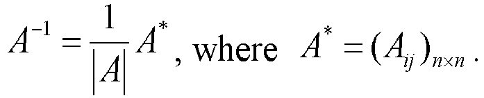
- It is assumed that in this slot, the autocorrelation matrix of the common signal at a specified sampling position is

antenna 1, a 22 corresponds to an autocorrelation matrix of a signal onantenna 2, and aNN corresponds to an autocorrelation matrix of a signal on antenna N. For a case with one antenna, an autocorrelation inverse matrix of a signal is calculated from a reciprocal of a 11 or a 22 according to an antenna index, such as

- According to the antenna index, the autocorrelation inverse matrices on two antennas at the sampling position are arranged according to antenna index to form a vector:
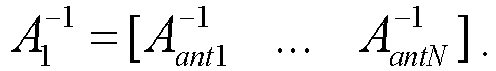
- The

- The autocorrelation inverse matrix of the signal on N antennas is calculated using a following equation:
- The

- In
step 103, an autocorrelation inverse matrix of the specified user signal is acquired from the autocorrelation inverse matrix of the cell common signal according to a result of the multipath matching for the specified user and multipath information. - According to the invention, the step in which the autocorrelation inverse matrix of the specified user signal is acquired from the autocorrelation inverse matrix of the cell common signal according to the result of the multipath matching for the specified user and the multipath information includes steps described below.
- A sampling position is calculated according to the result of the multipath matching for the specified user and the multipath information; and
the autocorrelation inverse matrix of the specified user signal is selected at the sampling position from the autocorrelation inverse matrix of the cell common signal according to the sampling position and in combination with an antenna index. - In a specific embodiment, the step in which the sampling position is calculated according to the result of the multipath matching for the specified user and the multipath information includes a step described below.
- For more than one multipath succeeding in the multipath matching for the specified user, the sampling position is obtained according to a delay relationship among the more than one multipath succeeding in the multipath matching for the specified user; or
for a multipath failing in the multipath matching for the specified user, the sampling position is obtained according to multipath delay on the multipath failing in the multipath matching for the specified user. - It is assumed that
user 1 has n paths succeeding in the multipath matching with delay of τ iA1 ,r1 ,···,τiAn ,rn respectively, where i A1,···,iAn respectively represent antenna index, r 1,···,rn represent multipath index, and n ∈ {2,3,4}. It is necessary to use a relationship among the delay of the n paths to obtain a sampling position, and then search for a corresponding matrix. According to judgment criteria for the multipath matching shown inFIG. 2 . there may be three cases for determination of the sampling position. - When n paths have same delay, i.e.,

A1 ,r1 , and τ 1 is brought intoequation 1 for calculating the sampling position. - When a deviation of 1/8 chip exists between maximum delay and minimum delay of n paths, i.e.,

Aj,rj ), and τ 1 is brought intoequation 1 for calculating the sampling position. - When a deviation of 1/4 chip exists between the maximum delay and the minimum delay of n paths, i.e.,

Aj,rj ) +1, and τ 1 is brought intoequation 1 for calculating the sampling position. - After the sampling position of the n multipaths succeeding in the multipath matching is obtained, the autocorrelation inverse matrix at the sampling position may be selected from R_rake in combination with the antenna index.
- For a multipath failing in the multipath matching for
user 1, a corresponding element will be selected from the autocorrelation inverse matrix of the common signal according to multipath delay on the multipath and antenna index. - Still taking results of the multipath matching with 4 antennas in
FIG. 3 as an example, for a case where 4 paths are successfully matched, the minimummultipath delay 1 is selected and brought it intoequation 1 to obtain asampling position 1, and then a matrix corresponding to the 4 paths is R_rake(1), as shown inresult 1 of the multipath matching inFIG. 6 . For a case of partial matching, for example, 3 paths onantennas multipath delay 29 is selected and brought it into τ 1 = min (τiAj,rj ) + 1 to obtain τ 1 of 30; the value of 30 is brought intoequation 1 to get a sampling position of 6, so corresponding elements ofantennas result 5 of the multipath matching shown inFIG. 6 . For one or more multipaths failing in the multipath matching, thesampling position 1 is directly obtained according to the multipath delay, and then second element along the diagonal is selected from R_rake(1) as the autocorrelation matrix, as shown in matchingresult 4 ofFIG. 6 . A matrix obtained from the above results of the multipath matching of those 5 groups is the autocorrelation matrix of the signal for this user. - An autocorrelation matrix of a signal corresponding to other users may also be calculated by the same method and will not be repeated here.
- In
step 104, a combined weight for the specified user is calculated according to a channel estimation value of the specified user and the autocorrelation inverse matrix of the specified user signal. - In an example, before the combined weight for the specified user is calculated according to the channel estimation value of the specified user and the autocorrelation inverse matrix of the specified user signal, the method further includes a step described below.
- Calculation of the channel estimation value of the specified user is performed according to a result of modulation and demodulation of a control channel.
- In an example, the modulation and demodulation of the control channel includes a step described below.
- The control channel is modulated and demodulated according to the uplink sampled antenna data and the multipath information.
- In an example, the multipath information is determined in steps described below.
- The multipath position of the specific user is searched for and determined; and the multipath information is obtained based on a result of the searching and determination.
- In an example, when a RAKE user performs spatial IRC processing, calculation of the combined weight will be implemented according to the result of the multipath matching.
- For two multipaths succeeding in the multipath matching, accurate channel estimation values of the two multipaths may be selected to form a 2*5 matrix:

- Since the autocorrelation inverse matrix of the signal is calculated in an order of
antenna 1 andantenna 2, in order to facilitate calculation, the first row in the above equation is used for storing the accurate channel estimation value corresponding to the multipath onantenna 1 and the second row is used for storing the accurate channel estimation value corresponding to the multipath onantenna 2. - Combining the obtained autocorrelation matrix of the signal corresponding to the two multipaths, the calculation equation of the spatial IRC for these two multipaths is:

- For a multipath failing in the multipath matching, a corresponding channel estimation value is searched out first to form a 1*5 vector:

- Combining an obtained signal autocorrelation matrix corresponding to the multipath, the calculation equation of the spatial IRC for the multipath is:

- It should be noted that, when N is relatively large, e.g., N>=3, the autocorrelation matrix has a dimension of N*N, which leads to relatively complex calculation for directly obtaining the inverse matrix, may refer to an ARAKE receiver method, a system of linear equations may be solved using a Gauss-Saidel iteration method to obtain the combined weight.
- Assuming an autocorrelation matrix corresponding to these N multipaths is tmp_RN , the combined weight is:


- In
step 105, a data channel of the specified user is modulated and demodulated based on the combined weight for the specified user. - In an example, the step in which the data channel of the specified user is modulated and demodulated based on the combined weight for the specified user includes an operation described below.
- According to the uplink sampling antenna data, the multipath information and the combined weight of the specific user, the data channel of the specified user is demodulated and modulated.
- Further, the method further includes a step described below.
- Data from modulation and demodulation of the data channel of the specified user is output to the BBU side.
- In the technical solution of the embodiments of the disclosure, because of a large number of RAKE users corresponding to a same RRU, it is impossible to calculate the correlation matrix of interference and noise for each RAKE user and find its inverse, which will make the entire system to have high computational complexity and cannot be realized. All RAKE users corresponding to the same RRU share data of multiple antennas on the RRU, those data can be used for calculating an autocorrelation matrix of a receiving signal as an approximate estimate of the covariance matrix of interference and noise, and obtaining an autocorrelation inverse matrix. Then, according to multipath delay of each RAKE user, an autocorrelation inverse matrix of the signal of each user may be obtained through simple matrix operations, thus makes RAKE users to obtain IRC gain with a minimum calculation amount.
- According to the method provided by the embodiments of the disclosure, the problem of extremely high computational complexity in the IRC processing of a RAKE receiver of the BBU side can be solved, the computational complexity can be greatly reduced, and meanwhile the demodulation performance of the uplink data channel can also be greatly improved.
- The interference suppression method of the present invention will be described in details below with reference to specific implementation scenarios.
- Illustratively, processing accuracy of 1/8 chip and N antennas are taken as an example for detailed description.
- If there are 8 samples on each chip, these 8 values should be considered for x, i.e., x=0, x=1/8, x=1/4, x=3/8, x=1/2, x=5/8, x=3/4 and x=7/8. Multipath delay of all RAKE users may be mapped into


- Assuming zU (k,iA ) as all valid antenna data by 8-times sampling in a slot, where k ∈ [0,2560*8-1] is a sample index of antenna data; iA ∈ {1, 2, ..., N} is an antenna index.
- It is assumed that in this slot, data of N antennas with a sampling index of kU form a vector:


- Here, R_raketmp (iS ) obtained from the calculation may represent not only the autocorrelation inverse matrix on N antennas, but also include results of signal autocorrelation calculation on the N antennas. Then, the calculation of the autocorrelation inverse matrix of the common signal needs to be processed separately according to the number of antennas.
- It is assumed that in this slot, the autocorrelation matrix of the common signal at the specified sampling position is

antenna 1, and a 22 corresponds to an autocorrelation matrix of a signal onantenna 2. For a case of only one antenna, an autocorrelation inverse matrix of the signal is calculated from a reciprocal of a 11 or a 22 according to an antenna index, such as

- According to the antenna index, the autocorrelation inverse matrices on the two antennas at the sampling position are arranged according to antenna index to form a vector:

- The

- The autocorrelation inverse matrix of the signal on the two antennas is calculated using a following equation:

- The

- Further, processing accuracy of 1/8 chip and 2 antennas are taken as an example for a detailed description below.
-
FIG. 7 shows a schematic diagram of a successful multipath matching with 2 antennas. In Case1 to Case3 ofFIG. 7 , the deviation of multipath delay between the 2 antennas is equal to or less than 1/4 chip; and in Case1 to Case5, the deviation of multipath delay between the 2 antennas is equal to or less than 1/2 chip. An example of a specific multipath matching process will be illustrated as follows. - Multi-paths on each of the two antennas are sorted according to a search result. τi
A ,r represents multipath delay, where iA ∈ {1,2} is an antenna index, r is a multipath index. It is assumed that there are n paths and m paths on those 2 antennas respectively. - The delay of respective paths on
antenna 1 is sorted to form a vector: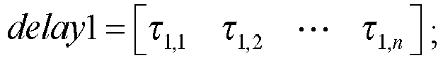
antenna 2 is sorted to form a vector:
- The multipath matching using delay of 1/4 chip includes steps described below.
- The delay of respective paths on
antenna 1 is taken as reference. First, delay2 is searched for a path which has an absolute value of a deviation from τ 1,1 not exceeding 1/4 chip. If this path exists, then multipath matching succeeds and these two multipaths are recorded; otherwise, delay2 is search for a path which has an absolute value of a deviation from τ 1,2 not exceeding 1/4 chip, and so on. - It should be noted that, each searching operation in delay2 is performed for an unmatched multipath in sequence.
- In a present system, two multipaths on a same antenna have a deviation no less than 3/4 chip. In order to perform a preferred selection of two multipaths with a smaller deviation in the multipath matching, the multipath matching according to the deviation of 1/2 chip may include two steps describe below.
- In first step, whether there is a multipath with a deviation of 1/4 chip is determined. The delay of respective paths on
antenna 1 is taken as reference. First, delay2 is searched for a multipath, which has an absolute value of a deviation from τ 1,1 not exceeding 1/4 chip. If the multipath exists, multipath matching succeeds and these two multipaths are recorded; otherwise, delay2 is searched for a multipath which has an absolute value of a deviation from τ 1,2 not exceeding 1/4 chip, and so on. - In second step, whether there is a multipath with a deviation of 1/2 chip is determined. This step is performed for unmatched multipaths after the first step. The delay of respective multipaths on
antenna 1 is still taken as reference. It is assumed that after the first step delay of τ 1,i in delay1 fails in the matching, the unmatched multipaths in delay2 is searched for a multipath which has an absolute value of a deviation from τ 1,i not exceeding 1/2 chip. If the multipath exists, then multipath matching succeeds and these two multipaths are recorded; otherwise, the matching is perfomed on a next multipath in delay1. - It should be noted that, even after the matching is completed, there may still be one or more unmatched multipaths in delay1 and delay2.
-
FIG. 8 shows a schematic diagram of multipath matching with 2 antennas. InFIG. 8 delay=[2 11 19], a matching result includes two successfully matched multipaths and two unmatched multipaths. -
FIG. 9 is a flowchart of calculating an autocorrelation inverse matrix of a specific user. As shown inFIG. 9 , it is assumed thatuser 1 has two successfully matched multipaths with delay of τ 1,a and τ 2,b respectively. A relationship between τ 1,a and τ 2,b is used for obtaining a sampling position, and a corresponding matrix is searched out. According to the judgment criteria of the multipath matching, there are five cases for determination of the sampling position. - When the two multipaths have same delay, i.e., τ 1,a = τ 2,b = τ 1, the sampling position may be calculated according to
equation 2 directly using τ 1. - When the two multipaths have delay of 1/8 chip, i.e., |τ 1, a -τ 2,b | =1, then τ 1 = min(τ 1,a ,τ 2,b ), τ 1 is brought into
equation 2 to calculate the sampling position. - When the two multipaths have delay of 1/4 chip, i.e., |τ 1, a -τ 2,b = 2, then τ 1 = (τ 1,a + τ 2,b )/2, τ 1 is brought into
equation 2 to calculate the sampling position. - When the two multipaths have delay of 3/8 chip, i.e., |τ 1, a -τ 2,b |= 3, then τ 1 = min(τ 1,a ,τ 2,b )+ 1, τ 1 is brought into
equation 2 to calculate the sampling position. - When the two multipaths have delay of 1/2 chip, i.e., |τ 1, a -τ 2,b | = 4, then τ 1 = (τ 1,a + τ 2,b )/ 2, τ 1 is brought into
equation 2 to calculate the sampling position. - In easel to
case 3, the deviation of delay between two multipaths is no more than 1/4. - After the sampling position of the successfully matched multipaths is obtained, an autocorrelation inverse matrix at the sampling position may be selected from invR2(iS ).
- For a multipath failing in the multipath matching for
user 1, an autocorrelation inverse matrix of this multipath is searched out according to the antenna index respectively. It is assumed that a multipath failing in the multipath matching onantenna 1 has delay of τ 1,i . τ1,i is brought intoequation 2 to obtain the sampling position, and invR1(iS ) is searched for an element corresponding to the sampling position onantenna 1. It is assumed that a multipath failing in multipath matching onantenna 2 has delay of τ 2,j . After the sampling position is obtained using the same method, invR1(iS ) is searched for an element corresponding to the sampling position onantenna 2. - It can be seen that, compared with the algorithm for calculating and inverting the correlation matrix of interference and noise for respective users, calculation complexity of the entire system is reduced and the calculation amount of calculating and inverting the correlation matrix of interference and noise in IRC is also reduced to an acceptable range.
- The technical solutions described in this example propose use of the calculation of the autocorrelation matrix for a same RRU antenna instead of respective users as an approximate estimation of the covariance matrix of interference and noise, which greatly reduces calculation complexity of the system. According to multipath delay of users, a simple algorithm may be applied, and the correlation matrix and its inverse matrix of a respective user is obtained by sharing the autocorrelation matrix and inverse matrix, so that a greater gain is guaranteed for each user.
-
FIG. 10 is a simulated comparison diagram of RAKE and RAKE_IRC with a ratio of 6 dB of interference user to benefited user according to an embodiment of the present invention. It may be seen inFIG. 10 , compared with the existing RAKE technology, the data demodulation gain gets larger. This significantly increases the data demodulation gain, enhances the signal-to-noise ratio, and achieves the purpose of increasing system capacity. -
FIG. 11 is a block diagram of RAKE IRC architecture according to an example. As shown inFIG. 11 , the architecture diagram mainly includes an upsampling module A, a common signal autocorrelation matrix generation module B, a common signal autocorrelation matrix inversion module C, a multipath searching module D, a multipath matching calculation module F, a specified user signal autocorrelation inverse matrix generation module G, a specified user signal weight calculation module H, a control channel demodulation module M, a data channel demodulation module E, and a refined channel estimate (RCE) calculation module P. - The upsampling module A is responsible for interpolation calculation of antenna data to improve sampling accuracy.
- The common signal autocorrelation matrix generation module B is responsible for generating an autocorrelation matrix of the common signal for each time slot in the cell (RRU).
- The common signal autocorrelation matrix inversion module C is responsible for generating an autocorrelation inverse matrix of the common signal for each time slot in the cell (RRU).
- The multipath searching module D is responsible for searching and determining a multipath position of a user.
- The multipath matching calculation module F is responsible for determination and calculation of matching multiple multipaths of the specific user according to a result of multipath search.
- The specified user autocorrelation inverse matrix generation module G is responsible for obtaining the autocorrelation inverse matrix of the specific user according to a determination result of multipath matching for the specific user and the autocorrelation inverse matrix of the common signal.
- The specific user signal weight calculation module H is responsible for calculating the weight of the specific user signal.
- The control channel demodulation module M is responsible for demodulation and modulation of the control channel.
- The data channel demodulation module E is responsible for demodulation and modulation of the data channel.
- The RCE calculation module P is responsible for calculating channel estimation according to a result of the control channel demodulation and modulation.
- The modules A, C, D, M, E and P may be implemented in the existing art.
- Those skilled in the art should understand that, the functions of the modules in the architectural diagram of the example can be understood with reference to the relevant description of the interference suppression method described above, and will not be repeated here.
- These examples of the disclosure provide a RAKE IRC demodulation solution, which can effectively upgrade original solution of pure RAKE demodulation. The RAKE IRC demodulation solution may be implemented through addition of only a new calculation module to the original architecture, and has good compatibility.
- The embodiments of the present invention provide an interference suppression device.
FIG. 12 shows a block diagram of an interference suppression device. The interference suppression device includes adetermination module 21, amatching module 22, anacquisition module 23, acalculation module 24 and aprocessing module 25. - The
determination module 21 is configured to determine an autocorrelation inverse matrix of a cell common signal according to uplink sampling antenna data. - The
matching module 22 is configured to perform multipath matching for a specified user according to the uplink sampling antenna data. - The
acquisition module 23 is configured to acquire an autocorrelation inverse matrix of a specified user signal from the autocorrelation inverse matrix of the cell common signal according to a result of the multipath matching for the specified user and multipath information. - The
calculation module 24 is configured to calculate a combined weight for the specified user according to a channel estimation value of the specified user and the autocorrelation inverse matrix of the specified user signal. - The
processing module 25 is configured to modulate and demodulate a data channel of the specified user based on the combined weight for the specified user. - In an optional embodiment, the
determination module 21 is further configured to: - calculate an autocorrelation matrix of the cell common signal according to the uplink sampling antenna data; and
- obtain the autocorrelation inverse matrix of the cell common signal according to the autocorrelation matrix of the cell common signal.
- In an optional embodiment, the
matching module 22 is further configured to: - perform multipath matching for the specified user according to the uplink sampling antenna data before the
determination module 21 calculates the autocorrelation matrix of the cell common signal according to the uplink sampling antenna data; - perform multipath matching for the specified user according to the uplink sampling antenna data after the
determination module 21 obtains the autocorrelation inverse matrix of the cell common signal according to the autocorrelation matrix of the cell common signal; or - perform multipath matching for the specified user according to the uplink sampling antenna data after the
determination module 21 calculates the autocorrelation matrix of the cell common signal according to the uplink sampling antenna data and before thedetermination module 21 obtains the autocorrelation inverse matrix of the cell common signal according to the autocorrelation matrix of the cell common signal. - In an optional embodiment, the
determination module 21 is further configured to:
calculate the autocorrelation matrix of the cell common signal according to a sampling position index and a chip index. - In an optional embodiment, the
matching module 22 is further configured to: - search for one or more multipaths with same delay on multiple antennas of the specified user in the cell;
- store multipaths with the same delay in a same structure, each multipath information being only stored in one structure.
- According to the invention, the
acquisition module 23 is further configured to: - calculate a sampling position according to the result of the multipath matching for the specified user and the multipath information; and
- select the autocorrelation inverse matrix of the specified user signal at the sampling position from the autocorrelation inverse matrix of the cell common signal according to the sampling position and in combination with an antenna index.
- In an optional embodiment, the
acquisition module 23 is further configured to: - for more than one multipath succeeding in the multipath matching for the specified user, obtain the sampling position according to a delay relationship among the more than one multipath succeeding in the multipath matching for the specified user; or
- for a multipath failing in the multipath matching for the specified user, obtain the sampling position according to multipath delay on the multipath failing in the multipath matching for the specified user.
- Those skilled in the art should understand that, functions of various processing units in the interference suppression device according to the embodiments of the present invention may be understood with reference to the above description of the interference suppression method. Each processing unit in the interference suppression device according to the embodiments of the present invention can be realized by an analog circuit for implementation of the functions described in the embodiments of the present invention, or by software performing the functions described in the embodiments of the present invention on an intelligent terminal.
- In this embodiment, the
determination module 21, thematching module 22, theacquisition module 23, thecalculation module 24 and theprocessing module 25 included in the interference suppression device may be implemented by a central processing unit (CPU), a digital signal processor (DSP), a programmable gate array (FPGA), etc. in the interference suppression device or the terminal to which the interference suppression device belongs in practical applications. - The interference suppression device according to the embodiments of the disclosure can solve the problem of the extremely high computational complexity in the IRC processing of a RAKE receiver on the BBU side, so that the computational complexity can be greatly reduced, and the demodulation performance of the uplink data channel can be greatly improved.
- The embodiments of the disclosure also disclose a computer storage medium. The computer storage medium stores one or more programs, which may be executed by one or more processors to implement steps described below.
- An autocorrelation inverse matrix of a cell common signal is determined according to uplink sampling antenna data;
- multipath matching is performed according to the uplink sampling antenna data;
- an autocorrelation inverse matrix of a specified user signal is acquired from the autocorrelation inverse matrix of the cell common signal according to a result of the multipath matching for the specified user and multipath information;
- a combined weight for the specified user is calculated according to a channel estimation value of the specified user and the autocorrelation inverse matrix of the specified user signal; and
- a data channel of the specified user is modulated and demodulated based on the combined weight for the specified user.
- As an embodiment, when the step in which according to uplink sampling antenna data, an autocorrelation inverse matrix of a cell common signal is determined is implemented, the one or more programs may further be executed by one or more processors to implement following steps:
- an autocorrelation matrix of the cell common signal is calculated according to the uplink sampling antenna data; and
- the autocorrelation inverse matrix of the cell common signal is obtained according to the autocorrelation matrix of the cell common signal.
- As an embodiment, when the step in which the multipath matching is performed according to the uplink sampling antenna data is implemented, the one or more programs may further be executed by one or more processors to implement following steps:
- the multipath matching is performed before the autocorrelation matrix of the cell common signal is calculated according to the uplink sampling antenna data;
- the multipath matching is performed after the autocorrelation inverse matrix of the cell common signal is obtained according to the autocorrelation matrix of the cell common signal; or
- the multipath matching is performed after the autocorrelation matrix of the cell common signal is calculated according to the uplink sampling antenna data, and before the autocorrelation inverse matrix of the cell common signal is obtained according to the autocorrelation matrix of the cell common signal.
- As an embodiment, when the step in which the multipath matching is performed according to the uplink sampling antenna data is implemented, the one or more programs may further be executed by one or more processors to implement following steps:
the autocorrelation matrix of the cell common signal is calculated according to a sampling position index and a chip index. - As an embodiment, when the step of multipath matching is performed according to the uplink sampling antenna data is implemented, the one or more programs may further be executed by one or more processors to implement following steps:
- one or more multipaths with same delay are searched for on multiple antennas of the specified user in the cell; and
- the multipaths with the same delay are stored in a same structure, wherein each multipath information is stored in one structure.
- According to the invention, when the step in which the autocorrelation inverse matrix of the specified user signal is acquired from the autocorrelation inverse matrix of the cell common signal according to a result of the multipath matching for the specified user and multipath information, the one or more programs may further be executed by one or more processors to implement following steps:
- a sampling position is calculated according to the result of the multipath matching for the specified user and the multipath information; and
- the autocorrelation inverse matrix of the specified user signal is selected at the sampling position from the autocorrelation inverse matrix of the cell common signal according to the sampling position and in combination with an antenna index.
- Those skilled in the art should understand that, the functions of programs in the computer storage medium of this embodiment may be understood with reference to the relevant descriptions of the interference suppression method described in the previous embodiments.
- It may be understood that the devices and the methods disclosed in the embodiments of the present invention may be implemented in other manners. The device embodiments described above are merely illustrative. For example, unit division is merely a logical function division, and, in practice, the unit division may be implemented in other ways. For example, multiple units or components may be combined or may be integrated into another system, or some features may be omitted or not executed. In addition, coupling, direct coupling, or communication connections between the presented or discussed different components may be indirect coupling or communication connections, via interfaces, between devices or units, and may be electrical, mechanical or in other forms.
- The units described above as separate components may or may not be physically separated. Components presented as units may or may not be physical units, that is, may be located in one place or may be distributed over multiple network units. Part or all of these units may be selected according to practical requirements to achieve objects of the solutions in the embodiments of the present invention.
- Moreover, various function units in each of the multiple embodiments of the present invention may all be integrated in one second processing unit, or each unit may be used as a separate unit, or two or more units may be integrated into one unit. The integrated function unit may be implemented by hardware or may be implemented by hardware plus a software function unit.
- In the solutions of the embodiments of the present invention, an autocorrelation inverse matrix of a cell common signal is determined according to uplink sampling antenna data; multipath matching is performed according to the uplink sampling antenna data; an autocorrelation inverse matrix of a specified user signal is acquired from the autocorrelation inverse matrix of the cell common signal according to a result of the multipath matching for the specified user and multipath information; a combined weight for the specified user is calculated according to a channel estimation value of the specified user and the autocorrelation inverse matrix of the specified user signal; and a data channel of the specified user is modulated and demodulated based on the combined weight for the specified user. In this way, the problem of high computational complexity in the IRC processing of a RAKE receiver on the BBU side can be solved, so that the computational complexity can be greatly reduced and the demodulation performance of the uplink data channel can be greatly improved.
Claims (13)
- An interference suppression method, comprising:determining an autocorrelation inverse matrix of a cell common signal according to uplink sampling antenna data (101);performing multipath matching for a specified user according to the uplink sampling antenna data (102);acquiring an autocorrelation inverse matrix of a specified user signal from the autocorrelation inverse matrix of the cell common signal according to a result of the multipath matching for the specified user and multipath information (103);calculating a combined weight for the specified user according to a channel estimation value of the specified user and the autocorrelation inverse matrix of the specified user signal; andmodulating and demodulating a data channel of the specified user based on the combined weight for the specified user (104);wherein acquiring the autocorrelation inverse matrix of the specified user signal from the autocorrelation inverse matrix of the cell common signal according to the result of the multipath matching for the specified user and the multipath information comprises:calculating a sampling position according to the result of the multipath matching for the specified user and the multipath information; andselecting the autocorrelation inverse matrix of the specified user signal at the sampling position from the autocorrelation inverse matrix of the cell common signal according to the sampling position and in combination with an antenna index.
- The interference suppression method according to claim 1, wherein determining the autocorrelation inverse matrix of the cell common signal according to the uplink sampling antenna data comprises:calculating an autocorrelation matrix of the cell common signal according to the uplink sampling antenna data (101a); andobtaining the autocorrelation inverse matrix of the cell common signal according to the autocorrelation matrix of the cell common signal (101b).
- The interference suppression method according to claim 2, wherein the step of performing multipath matching for the specified user according to the uplink sampling antenna data is implemented:before calculating the autocorrelation matrix of the cell common signal according to the uplink sampling antenna data;after obtaining the autocorrelation inverse matrix of the cell common signal according to the autocorrelation matrix of the cell common signal; orafter calculating the autocorrelation matrix of the cell common signal according to the uplink sampling antenna data, and before obtaining the autocorrelation inverse matrix of the cell common signal according to the autocorrelation matrix of the cell common signal.
- The interference suppression method according to claim 2, wherein determining the autocorrelation matrix of the cell common signal according to uplink sampling antenna data comprises:
calculating the autocorrelation matrix of the cell common signal according to a sampling position index and a chip index. - The interference suppression method according to claim 1, wherein performing multipath matching for the specified user according to the uplink sampling antenna data comprises:searching for one or more multipaths with same delay on multiple antennas of the specified user in the cell; andstoring the multipaths with the same delay in a same structure, wherein each multipath information is stored in one structure.
- The interference suppression method according to claim 1, wherein calculating the sampling position according to the result of the multipath matching for the specified user and the multipath information comprises:for more than one multipath succeeding in the multipath matching for the specified user, obtaining the sampling position according to a delay relationship among the more than one multipath succeeding in the multipath matching for the specified user; orfor a multipath failing in the multipath matching for the specified user, obtaining the sampling position according to multipath delay on the multipath failing in the multipath matching for the specified user.
- An interference suppression device, comprising:a determination module (21), which is configured to determine an autocorrelation inverse matrix of a cell common signal according to uplink sampling antenna data;a matching module (22), which is configured to perform multipath matching for a specified user according to the uplink sampling antenna data;an acquisition module (23), which is configured to acquire an autocorrelation inverse matrix of a specified user signal from the autocorrelation inverse matrix of the cell common signal according to a result of the multipath matching for the specified user and multipath information;a calculation module (24), which is configured to calculate a combined weight for the specified user according to a channel estimation value of the specified user and the autocorrelation inverse matrix of the specified user signal; anda processing module (25), which is configured to modulate and demodulate a data channel of the specified user based on the combined weight for the specified user;wherein the acquisition module (23) is further configured tocalculate a sampling position according to the result of the multipath matching for the specified user and the multipath information;select the autocorrelation inverse matrix of the specified user signal at the sampling position from the autocorrelation inverse matrix of the cell common signal according to the sampling position and in combination with an antenna index.
- The interference suppression device according to claim 7, wherein the determination module (21) is further configured to:calculate an autocorrelation matrix of the cell common signal according to the uplink sampling antenna data; andobtain the autocorrelation inverse matrix of the cell common signal according to the autocorrelation matrix of the cell common signal.
- The interference suppression device according to claim 8, wherein the matching module (22) is configured to:perform multipath matching for the specified user according to the uplink sampling antenna data before the determination module (21) calculates the autocorrelation matrix of the cell common signal according to the uplink sampling antenna data;perform multipath matching for the specified user according to the uplink sampling antenna data after the determination module (21) obtains the autocorrelation inverse matrix of the cell common signal according to the autocorrelation matrix of the cell common signal; orperform multipath matching for the specified user according to the uplink sampling antenna data after the determination module (21) calculates the autocorrelation matrix of the cell common signal according to the uplink sampling antenna data and before the determination module (21) obtains the autocorrelation inverse matrix of the cell common signal according to the autocorrelation matrix of the cell common signal.
- The interference suppression device according to claim 8, wherein the determination module (21) is further configured to:
calculate the autocorrelation matrix of the cell common signal according to a sampling position index and a chip index. - The interference suppression device according to claim 7, wherein the matching module (22) is further configured to:search for one or more multipaths with same delay on multiple antennas of the specified user in the cell;store the multipaths with the same delay in a same structure, wherein each multipath information is only stored in one structure.
- The interference suppression device according to claim 7, wherein the acquisition module (23) is further configured to:for more than one multipath succeeding in the multipath matching for the specified user, obtain the sampling position according to a delay relationship among the more than one multipath succeeding in the multipath matching for the specified user; orfor a multipath failing in the multipath matching for the specified user, obtain the sampling position according to multipath delay on the multipath failing in the multipath matching for the specified user.
- A computer storage medium, wherein the computer storage medium stores computer-executable instructions which, when executed by a computer, cause the computer to carry out the interference suppression method according to any one of the claims 1 to 6.
Applications Claiming Priority (2)
| Application Number | Priority Date | Filing Date | Title |
|---|---|---|---|
| CN201611146831.5A CN108233984B (en) | 2016-12-13 | 2016-12-13 | Interference suppression method and device |
| PCT/CN2017/085544 WO2018107664A1 (en) | 2016-12-13 | 2017-05-23 | Interference suppression method and device, and computer storage medium |
Publications (3)
| Publication Number | Publication Date |
|---|---|
| EP3557771A1 EP3557771A1 (en) | 2019-10-23 |
| EP3557771A4 EP3557771A4 (en) | 2020-08-26 |
| EP3557771B1 true EP3557771B1 (en) | 2021-09-08 |
Family
ID=62557941
Family Applications (1)
| Application Number | Title | Priority Date | Filing Date |
|---|---|---|---|
| EP17882147.6A Active EP3557771B1 (en) | 2016-12-13 | 2017-05-23 | Interference suppression method and device, and computer storage medium |
Country Status (5)
| Country | Link |
|---|---|
| EP (1) | EP3557771B1 (en) |
| CN (1) | CN108233984B (en) |
| ES (1) | ES2895250T3 (en) |
| HU (1) | HUE056641T2 (en) |
| WO (1) | WO2018107664A1 (en) |
Cited By (1)
| Publication number | Priority date | Publication date | Assignee | Title |
|---|---|---|---|---|
| RU2803526C1 (en) * | 2022-10-10 | 2023-09-14 | Федеральное государственное бюджетное образовательное учреждение высшего образования "Рязанский государственный радиотехнический университет имени В.Ф. Уткина" | Computer for interference suppression |
Families Citing this family (4)
| Publication number | Priority date | Publication date | Assignee | Title |
|---|---|---|---|---|
| CN111836184B (en) * | 2019-04-16 | 2022-02-25 | 华为技术有限公司 | Method, device and equipment for processing data and readable storage medium |
| CN110289892B (en) * | 2019-05-23 | 2022-07-15 | 武汉虹信科技发展有限责任公司 | Data transmission method and communication base station |
| CN113556301B (en) * | 2020-04-24 | 2023-01-10 | 大唐移动通信设备有限公司 | Signal processing method and device |
| CN114785426B (en) * | 2022-03-30 | 2023-11-03 | 西安宇飞电子技术有限公司 | Multi-antenna anti-interference method, device, equipment and computer readable storage medium |
Family Cites Families (6)
| Publication number | Priority date | Publication date | Assignee | Title |
|---|---|---|---|---|
| US8873650B2 (en) * | 2009-10-12 | 2014-10-28 | Motorola Mobility Llc | Configurable spatial channel information feedback in wireless communication system |
| CN102104562B (en) * | 2009-12-17 | 2013-08-21 | 中兴通讯股份有限公司 | Multi-antenna interference rejection combining method and device |
| US8971386B2 (en) * | 2011-08-17 | 2015-03-03 | Telefonaktiebolaget L M Ericsson (Publ) | Receiver unit and method for suppressing interference in a multipath radio signal |
| CN103138820B (en) * | 2011-11-29 | 2017-11-03 | 邳州高新区生物医药研究院有限公司 | Signal detecting method and device under VAMOS patterns |
| CN103825847B (en) * | 2012-11-19 | 2018-03-20 | 中兴通讯股份有限公司 | A kind of channel disturbance offsets method, apparatus and base station |
| CN105959049B (en) * | 2016-07-14 | 2019-02-12 | 大唐联诚信息系统技术有限公司 | A kind of signal processing method and device |
-
2016
- 2016-12-13 CN CN201611146831.5A patent/CN108233984B/en active Active
-
2017
- 2017-05-23 HU HUE17882147A patent/HUE056641T2/en unknown
- 2017-05-23 EP EP17882147.6A patent/EP3557771B1/en active Active
- 2017-05-23 ES ES17882147T patent/ES2895250T3/en active Active
- 2017-05-23 WO PCT/CN2017/085544 patent/WO2018107664A1/en unknown
Cited By (1)
| Publication number | Priority date | Publication date | Assignee | Title |
|---|---|---|---|---|
| RU2803526C1 (en) * | 2022-10-10 | 2023-09-14 | Федеральное государственное бюджетное образовательное учреждение высшего образования "Рязанский государственный радиотехнический университет имени В.Ф. Уткина" | Computer for interference suppression |
Also Published As
| Publication number | Publication date |
|---|---|
| EP3557771A4 (en) | 2020-08-26 |
| ES2895250T3 (en) | 2022-02-18 |
| HUE056641T2 (en) | 2022-03-28 |
| EP3557771A1 (en) | 2019-10-23 |
| CN108233984B (en) | 2020-03-31 |
| WO2018107664A1 (en) | 2018-06-21 |
| CN108233984A (en) | 2018-06-29 |
Similar Documents
| Publication | Publication Date | Title |
|---|---|---|
| Talwar et al. | Blind separation of synchronous co-channel digital signals using an antenna array. I. Algorithms | |
| EP3557771B1 (en) | Interference suppression method and device, and computer storage medium | |
| KR100317518B1 (en) | Detectors for cdma systems | |
| EP1062746B1 (en) | Practical space-time radio method for cdma communication capacity enhancement | |
| KR100770875B1 (en) | Beam forming apparatus and method using estimating interference power in array antenna system | |
| KR100735813B1 (en) | Method of generating weighted vector in the development of smart antennas for IMT-2000 CDMA wireless communication | |
| US6501747B1 (en) | Manifold assisted channel estimation and demodulation for CDMA systems in fast fading environments | |
| US6549565B1 (en) | Code division multiple access system and method of operation with improved signal acquisition and processing | |
| RU2232485C2 (en) | Procedure to form directivity pattern of antenna and device for its realization | |
| CN100544234C (en) | Advanced whitener device-the RAKE receiver that is used for the WCDMA terminal | |
| KR20050117436A (en) | Interference power measurement apparatus and method required space-time beam forming | |
| US6324160B1 (en) | Adaptive receiver for CDMA base stations | |
| Tsatsanis et al. | Constrained optimization methods for direct blind equalization | |
| CN105933254A (en) | Beam space based channel estimation method in millimeter wave multi-cell and multi-antenna system | |
| Koivisto et al. | Blind despreading of short-code DS-CDMA signals in asynchronous multi-user systems | |
| Liu et al. | Seismic data compression using online double-sparse dictionary learning schemes | |
| EP2949048A1 (en) | Method and system of receiver parametric computation for multiple-input multiple-output (mimo) transmission | |
| Choi | A receiver of simple structure for antenna array CDMA systems | |
| KR20000060728A (en) | Rake receiver in cdma adaptive array antenna system | |
| KR100241503B1 (en) | Tranceiving signal processing method and apparatus for moile communication system using array antenna system | |
| EP1058401B1 (en) | Code assignment in a CDMA wireless system | |
| Pelletier et al. | Group-based space-time multiuser detection with user sharing | |
| KR20020057594A (en) | Apparatus for smart antenna using phase estimation | |
| De Lamare et al. | Blind space–time joint channel and direction of arrival estimation for DS-CDMA systems | |
| Pelletier et al. | Group optimal space-time MUD with beamforming |
Legal Events
| Date | Code | Title | Description |
|---|---|---|---|
| STAA | Information on the status of an ep patent application or granted ep patent |
Free format text: STATUS: THE INTERNATIONAL PUBLICATION HAS BEEN MADE |
|
| PUAI | Public reference made under article 153(3) epc to a published international application that has entered the european phase |
Free format text: ORIGINAL CODE: 0009012 |
|
| STAA | Information on the status of an ep patent application or granted ep patent |
Free format text: STATUS: REQUEST FOR EXAMINATION WAS MADE |
|
| 17P | Request for examination filed |
Effective date: 20190712 |
|
| AK | Designated contracting states |
Kind code of ref document: A1 Designated state(s): AL AT BE BG CH CY CZ DE DK EE ES FI FR GB GR HR HU IE IS IT LI LT LU LV MC MK MT NL NO PL PT RO RS SE SI SK SM TR |
|
| AX | Request for extension of the european patent |
Extension state: BA ME |
|
| DAV | Request for validation of the european patent (deleted) | ||
| DAX | Request for extension of the european patent (deleted) | ||
| A4 | Supplementary search report drawn up and despatched |
Effective date: 20200727 |
|
| RIC1 | Information provided on ipc code assigned before grant |
Ipc: H04B 1/7115 20180101AFI20200721BHEP |
|
| GRAP | Despatch of communication of intention to grant a patent |
Free format text: ORIGINAL CODE: EPIDOSNIGR1 |
|
| STAA | Information on the status of an ep patent application or granted ep patent |
Free format text: STATUS: GRANT OF PATENT IS INTENDED |
|
| RIC1 | Information provided on ipc code assigned before grant |
Ipc: H04B 7/08 20060101ALI20210430BHEP Ipc: H04B 1/7115 20180101AFI20210430BHEP |
|
| INTG | Intention to grant announced |
Effective date: 20210602 |
|
| GRAS | Grant fee paid |
Free format text: ORIGINAL CODE: EPIDOSNIGR3 |
|
| GRAA | (expected) grant |
Free format text: ORIGINAL CODE: 0009210 |
|
| STAA | Information on the status of an ep patent application or granted ep patent |
Free format text: STATUS: THE PATENT HAS BEEN GRANTED |
|
| AK | Designated contracting states |
Kind code of ref document: B1 Designated state(s): AL AT BE BG CH CY CZ DE DK EE ES FI FR GB GR HR HU IE IS IT LI LT LU LV MC MK MT NL NO PL PT RO RS SE SI SK SM TR |
|
| REG | Reference to a national code |
Ref country code: GB Ref legal event code: FG4D |
|
| REG | Reference to a national code |
Ref country code: AT Ref legal event code: REF Ref document number: 1429505 Country of ref document: AT Kind code of ref document: T Effective date: 20210915 Ref country code: CH Ref legal event code: EP |
|
| REG | Reference to a national code |
Ref country code: IE Ref legal event code: FG4D |
|
| REG | Reference to a national code |
Ref country code: DE Ref legal event code: R096 Ref document number: 602017045862 Country of ref document: DE |
|
| REG | Reference to a national code |
Ref country code: LT Ref legal event code: MG9D |
|
| REG | Reference to a national code |
Ref country code: NL Ref legal event code: MP Effective date: 20210908 |
|
| PG25 | Lapsed in a contracting state [announced via postgrant information from national office to epo] |
Ref country code: BG Free format text: LAPSE BECAUSE OF FAILURE TO SUBMIT A TRANSLATION OF THE DESCRIPTION OR TO PAY THE FEE WITHIN THE PRESCRIBED TIME-LIMIT Effective date: 20211208 Ref country code: LT Free format text: LAPSE BECAUSE OF FAILURE TO SUBMIT A TRANSLATION OF THE DESCRIPTION OR TO PAY THE FEE WITHIN THE PRESCRIBED TIME-LIMIT Effective date: 20210908 Ref country code: NO Free format text: LAPSE BECAUSE OF FAILURE TO SUBMIT A TRANSLATION OF THE DESCRIPTION OR TO PAY THE FEE WITHIN THE PRESCRIBED TIME-LIMIT Effective date: 20211208 Ref country code: SE Free format text: LAPSE BECAUSE OF FAILURE TO SUBMIT A TRANSLATION OF THE DESCRIPTION OR TO PAY THE FEE WITHIN THE PRESCRIBED TIME-LIMIT Effective date: 20210908 Ref country code: RS Free format text: LAPSE BECAUSE OF FAILURE TO SUBMIT A TRANSLATION OF THE DESCRIPTION OR TO PAY THE FEE WITHIN THE PRESCRIBED TIME-LIMIT Effective date: 20210908 Ref country code: HR Free format text: LAPSE BECAUSE OF FAILURE TO SUBMIT A TRANSLATION OF THE DESCRIPTION OR TO PAY THE FEE WITHIN THE PRESCRIBED TIME-LIMIT Effective date: 20210908 Ref country code: FI Free format text: LAPSE BECAUSE OF FAILURE TO SUBMIT A TRANSLATION OF THE DESCRIPTION OR TO PAY THE FEE WITHIN THE PRESCRIBED TIME-LIMIT Effective date: 20210908 |
|
| REG | Reference to a national code |
Ref country code: AT Ref legal event code: MK05 Ref document number: 1429505 Country of ref document: AT Kind code of ref document: T Effective date: 20210908 |
|
| REG | Reference to a national code |
Ref country code: ES Ref legal event code: FG2A Ref document number: 2895250 Country of ref document: ES Kind code of ref document: T3 Effective date: 20220218 |
|
| PG25 | Lapsed in a contracting state [announced via postgrant information from national office to epo] |
Ref country code: LV Free format text: LAPSE BECAUSE OF FAILURE TO SUBMIT A TRANSLATION OF THE DESCRIPTION OR TO PAY THE FEE WITHIN THE PRESCRIBED TIME-LIMIT Effective date: 20210908 Ref country code: GR Free format text: LAPSE BECAUSE OF FAILURE TO SUBMIT A TRANSLATION OF THE DESCRIPTION OR TO PAY THE FEE WITHIN THE PRESCRIBED TIME-LIMIT Effective date: 20211209 |
|
| REG | Reference to a national code |
Ref country code: HU Ref legal event code: AG4A Ref document number: E056641 Country of ref document: HU |
|
| PG25 | Lapsed in a contracting state [announced via postgrant information from national office to epo] |
Ref country code: AT Free format text: LAPSE BECAUSE OF FAILURE TO SUBMIT A TRANSLATION OF THE DESCRIPTION OR TO PAY THE FEE WITHIN THE PRESCRIBED TIME-LIMIT Effective date: 20210908 |
|
| PG25 | Lapsed in a contracting state [announced via postgrant information from national office to epo] |
Ref country code: IS Free format text: LAPSE BECAUSE OF FAILURE TO SUBMIT A TRANSLATION OF THE DESCRIPTION OR TO PAY THE FEE WITHIN THE PRESCRIBED TIME-LIMIT Effective date: 20220108 Ref country code: SM Free format text: LAPSE BECAUSE OF FAILURE TO SUBMIT A TRANSLATION OF THE DESCRIPTION OR TO PAY THE FEE WITHIN THE PRESCRIBED TIME-LIMIT Effective date: 20210908 Ref country code: SK Free format text: LAPSE BECAUSE OF FAILURE TO SUBMIT A TRANSLATION OF THE DESCRIPTION OR TO PAY THE FEE WITHIN THE PRESCRIBED TIME-LIMIT Effective date: 20210908 Ref country code: RO Free format text: LAPSE BECAUSE OF FAILURE TO SUBMIT A TRANSLATION OF THE DESCRIPTION OR TO PAY THE FEE WITHIN THE PRESCRIBED TIME-LIMIT Effective date: 20210908 Ref country code: PT Free format text: LAPSE BECAUSE OF FAILURE TO SUBMIT A TRANSLATION OF THE DESCRIPTION OR TO PAY THE FEE WITHIN THE PRESCRIBED TIME-LIMIT Effective date: 20220110 Ref country code: PL Free format text: LAPSE BECAUSE OF FAILURE TO SUBMIT A TRANSLATION OF THE DESCRIPTION OR TO PAY THE FEE WITHIN THE PRESCRIBED TIME-LIMIT Effective date: 20210908 Ref country code: NL Free format text: LAPSE BECAUSE OF FAILURE TO SUBMIT A TRANSLATION OF THE DESCRIPTION OR TO PAY THE FEE WITHIN THE PRESCRIBED TIME-LIMIT Effective date: 20210908 Ref country code: EE Free format text: LAPSE BECAUSE OF FAILURE TO SUBMIT A TRANSLATION OF THE DESCRIPTION OR TO PAY THE FEE WITHIN THE PRESCRIBED TIME-LIMIT Effective date: 20210908 Ref country code: CZ Free format text: LAPSE BECAUSE OF FAILURE TO SUBMIT A TRANSLATION OF THE DESCRIPTION OR TO PAY THE FEE WITHIN THE PRESCRIBED TIME-LIMIT Effective date: 20210908 Ref country code: AL Free format text: LAPSE BECAUSE OF FAILURE TO SUBMIT A TRANSLATION OF THE DESCRIPTION OR TO PAY THE FEE WITHIN THE PRESCRIBED TIME-LIMIT Effective date: 20210908 |
|
| REG | Reference to a national code |
Ref country code: DE Ref legal event code: R097 Ref document number: 602017045862 Country of ref document: DE |
|
| PLBE | No opposition filed within time limit |
Free format text: ORIGINAL CODE: 0009261 |
|
| STAA | Information on the status of an ep patent application or granted ep patent |
Free format text: STATUS: NO OPPOSITION FILED WITHIN TIME LIMIT |
|
| PG25 | Lapsed in a contracting state [announced via postgrant information from national office to epo] |
Ref country code: DK Free format text: LAPSE BECAUSE OF FAILURE TO SUBMIT A TRANSLATION OF THE DESCRIPTION OR TO PAY THE FEE WITHIN THE PRESCRIBED TIME-LIMIT Effective date: 20210908 |
|
| 26N | No opposition filed |
Effective date: 20220609 |
|
| PG25 | Lapsed in a contracting state [announced via postgrant information from national office to epo] |
Ref country code: SI Free format text: LAPSE BECAUSE OF FAILURE TO SUBMIT A TRANSLATION OF THE DESCRIPTION OR TO PAY THE FEE WITHIN THE PRESCRIBED TIME-LIMIT Effective date: 20210908 |
|
| REG | Reference to a national code |
Ref country code: DE Ref legal event code: R119 Ref document number: 602017045862 Country of ref document: DE |
|
| REG | Reference to a national code |
Ref country code: CH Ref legal event code: PL |
|
| REG | Reference to a national code |
Ref country code: BE Ref legal event code: MM Effective date: 20220531 |
|
| GBPC | Gb: european patent ceased through non-payment of renewal fee |
Effective date: 20220523 |
|
| PG25 | Lapsed in a contracting state [announced via postgrant information from national office to epo] |
Ref country code: MC Free format text: LAPSE BECAUSE OF FAILURE TO SUBMIT A TRANSLATION OF THE DESCRIPTION OR TO PAY THE FEE WITHIN THE PRESCRIBED TIME-LIMIT Effective date: 20210908 Ref country code: LU Free format text: LAPSE BECAUSE OF NON-PAYMENT OF DUE FEES Effective date: 20220523 Ref country code: LI Free format text: LAPSE BECAUSE OF NON-PAYMENT OF DUE FEES Effective date: 20220531 Ref country code: CH Free format text: LAPSE BECAUSE OF NON-PAYMENT OF DUE FEES Effective date: 20220531 |
|
| PG25 | Lapsed in a contracting state [announced via postgrant information from national office to epo] |
Ref country code: IE Free format text: LAPSE BECAUSE OF NON-PAYMENT OF DUE FEES Effective date: 20220523 Ref country code: FR Free format text: LAPSE BECAUSE OF NON-PAYMENT OF DUE FEES Effective date: 20220531 |
|
| PG25 | Lapsed in a contracting state [announced via postgrant information from national office to epo] |
Ref country code: GB Free format text: LAPSE BECAUSE OF NON-PAYMENT OF DUE FEES Effective date: 20220523 Ref country code: DE Free format text: LAPSE BECAUSE OF NON-PAYMENT OF DUE FEES Effective date: 20221201 Ref country code: BE Free format text: LAPSE BECAUSE OF NON-PAYMENT OF DUE FEES Effective date: 20220531 |
|
| PGFP | Annual fee paid to national office [announced via postgrant information from national office to epo] |
Ref country code: IT Payment date: 20230412 Year of fee payment: 7 Ref country code: ES Payment date: 20230605 Year of fee payment: 7 |
|
| PGFP | Annual fee paid to national office [announced via postgrant information from national office to epo] |
Ref country code: HU Payment date: 20220430 Year of fee payment: 7 |
|
| PG25 | Lapsed in a contracting state [announced via postgrant information from national office to epo] |
Ref country code: MK Free format text: LAPSE BECAUSE OF FAILURE TO SUBMIT A TRANSLATION OF THE DESCRIPTION OR TO PAY THE FEE WITHIN THE PRESCRIBED TIME-LIMIT Effective date: 20210908 Ref country code: CY Free format text: LAPSE BECAUSE OF FAILURE TO SUBMIT A TRANSLATION OF THE DESCRIPTION OR TO PAY THE FEE WITHIN THE PRESCRIBED TIME-LIMIT Effective date: 20210908 |