EP3556152B1 - Transmission power adjustments - Google Patents
Transmission power adjustments Download PDFInfo
- Publication number
- EP3556152B1 EP3556152B1 EP17917815.7A EP17917815A EP3556152B1 EP 3556152 B1 EP3556152 B1 EP 3556152B1 EP 17917815 A EP17917815 A EP 17917815A EP 3556152 B1 EP3556152 B1 EP 3556152B1
- Authority
- EP
- European Patent Office
- Prior art keywords
- network
- computing device
- transmission power
- peer
- connection
- Prior art date
- Legal status (The legal status is an assumption and is not a legal conclusion. Google has not performed a legal analysis and makes no representation as to the accuracy of the status listed.)
- Active
Links
- 230000005540 biological transmission Effects 0.000 title claims description 84
- 238000000034 method Methods 0.000 claims description 19
- 238000003032 molecular docking Methods 0.000 claims description 8
- 238000000060 site-specific infrared dichroism spectroscopy Methods 0.000 claims 2
- 230000003247 decreasing effect Effects 0.000 description 6
- 238000010586 diagram Methods 0.000 description 4
- 238000005516 engineering process Methods 0.000 description 4
- 238000004891 communication Methods 0.000 description 3
- 230000003287 optical effect Effects 0.000 description 2
- 230000004888 barrier function Effects 0.000 description 1
- 230000001419 dependent effect Effects 0.000 description 1
- 230000006870 function Effects 0.000 description 1
- 238000009434 installation Methods 0.000 description 1
- 230000007774 longterm Effects 0.000 description 1
- 238000010295 mobile communication Methods 0.000 description 1
- 230000006855 networking Effects 0.000 description 1
- 238000005457 optimization Methods 0.000 description 1
- 230000002093 peripheral effect Effects 0.000 description 1
Images


Classifications
-
- H—ELECTRICITY
- H04—ELECTRIC COMMUNICATION TECHNIQUE
- H04W—WIRELESS COMMUNICATION NETWORKS
- H04W52/00—Power management, e.g. TPC [Transmission Power Control], power saving or power classes
- H04W52/04—TPC
- H04W52/38—TPC being performed in particular situations
- H04W52/383—TPC being performed in particular situations power control in peer-to-peer links
-
- H—ELECTRICITY
- H04—ELECTRIC COMMUNICATION TECHNIQUE
- H04W—WIRELESS COMMUNICATION NETWORKS
- H04W52/00—Power management, e.g. TPC [Transmission Power Control], power saving or power classes
- H04W52/04—TPC
- H04W52/18—TPC being performed according to specific parameters
- H04W52/28—TPC being performed according to specific parameters using user profile, e.g. mobile speed, priority or network state, e.g. standby, idle or non transmission
- H04W52/281—TPC being performed according to specific parameters using user profile, e.g. mobile speed, priority or network state, e.g. standby, idle or non transmission taking into account user or data type priority
-
- H—ELECTRICITY
- H04—ELECTRIC COMMUNICATION TECHNIQUE
- H04W—WIRELESS COMMUNICATION NETWORKS
- H04W52/00—Power management, e.g. TPC [Transmission Power Control], power saving or power classes
- H04W52/04—TPC
- H04W52/18—TPC being performed according to specific parameters
- H04W52/28—TPC being performed according to specific parameters using user profile, e.g. mobile speed, priority or network state, e.g. standby, idle or non transmission
- H04W52/283—Power depending on the position of the mobile
-
- H—ELECTRICITY
- H04—ELECTRIC COMMUNICATION TECHNIQUE
- H04W—WIRELESS COMMUNICATION NETWORKS
- H04W52/00—Power management, e.g. TPC [Transmission Power Control], power saving or power classes
- H04W52/04—TPC
- H04W52/38—TPC being performed in particular situations
- H04W52/40—TPC being performed in particular situations during macro-diversity or soft handoff
-
- H—ELECTRICITY
- H04—ELECTRIC COMMUNICATION TECHNIQUE
- H04W—WIRELESS COMMUNICATION NETWORKS
- H04W52/00—Power management, e.g. TPC [Transmission Power Control], power saving or power classes
- H04W52/04—TPC
- H04W52/38—TPC being performed in particular situations
- H04W52/44—TPC being performed in particular situations in connection with interruption of transmission
Definitions
- Wireless network operating systems may utilize a networking standard.
- wireless network operating systems can utilize IEEE 802.11 standard.
- Wireless networks utilizing network operating systems can allow client devices to connect with access points within the wireless network.
- the network can include a plurality of access points that can each receive communication requests for client devices. Relatively large quantities of client devices can send communication requests to the plurality of access points.
- US 2013/324182 A1 discloses device-to-device, D2D, cross link power control systems and methods.
- a device such as a UE or WTRU may determine whether it may have simultaneous transmissions where at least one of the transmissions may include a cross link transmission.
- the device may further determine whether a total transmit power of the simultaneous transmissions may exceed a maximum transmit power of the device. If the device may have simultaneous transmissions and such transmissions may exceed the maximum transmit power, the device may reallocate power based on a priority or priority setting.
- the device may further determine a maximum cross link power, a maximum device power, and a cross link transmit power level such that the device may further control the power for transmissions based thereon.
- EP 1670183 A1 discloses a system and a method for controlling transmission power in a wireless local area network, WLAN, and more particularly, a system and a method for controlling transmission power in a WLAN that are capable of providing a WLAN service to terminals outside a service area by controlling the transmission power in the WLAN.
- link margin data of a station positioned at a hidden node of the WLAN is received from another station positioned in a service area, and the received link margin data is compared with preset link margin data for control of the transmission power in the WLAN.
- WO 2016/062666 A2 discloses a system, a user equipment and a base station for carrier selection in a wireless telecommunication system. This document is directed towards a system for co-existence optimizations of different radio technologies in a wireless telecommunication system. In particular, it relates to technology adapted to operate according to the IEEE 802.11 family of standards, commonly known as Wi-Fi or WLAN, and technology adapted to operate in accordance with mobile communication standards such as the "Long Term Evolution", or LTE, transmission technology.
- Computing devices can include transmitter to transmit wireless signals.
- computing devices can include a transmitter to transmit radio signals to a network device (e.g., access point, router, etc.).
- the computing devices can include a transmitter for WiFi connections.
- the computing device can utilize a WiFi transmitter for connecting to a local area network, a docking station (e.g., WiFi Direct, etc.), or other type of WiFi connections.
- the transmission power of the WiFi transmitter can be set to a maximum power or relatively high power level when network devices for a local area network or WiFi connections are at a relatively large distance from the computing device.
- the transmission power of the WiFi transmitter may not be adjustable and may be set to a highest power in order to ensure a strong connection between the computing device and the network devices as described herein.
- the highest available transmission power can provide considerable un-needed signal margin, especially in medium to short range distances between wireless devices. This un-needed margin of transmission power in areas with a greater quantity of computing devices utilizing wireless transmitters can cause signal noise that can interfere with signal quality of the computing devices within the area.
- an adjustable wireless transmitter e.g., adjustable WiFi transmitter
- the type of network can include a plurality of different network types with different network properties.
- Computing devices can connect to an infrastructure network connection or a peer to peer network connection.
- an infrastructure network connection can be a local area network connection and/or similar connection that utilizes a plurality of access points to transmit signals to and receive signals from the computing device.
- a peer to peer network connection can be a docking network connection that utilizes a network dock to transmit signals to and receive signals from the computing device.
- the infrastructure network connection can utilize access points that are positioned relatively far from the computing device. In these examples, a relatively greater transmission power can be utilized to ensure a strong connection with the access points.
- the peer to peer network connection can utilize a network dock or network docking station that can be positioned relatively close to the computing device. In these examples, a relatively lower transmission power can be utilized due to the relatively close proximity between the network docking station and the computing device.
- the network type is determined and the transmission power is adjusted based on the network type. For example, the transmission power can be increased to a maximum transmission power level when the computing device is connected to an infrastructure network connection and the transmission power can be decreased to a lower transmission power level when the computing device is connected to a peer to peer network connection. In this way, battery power can be reserved and noise created by the increased transmission power level can be reduced when the computing device is connected to the peer to peer network.
- Figure 1 illustrates an example environment 100 for transmission power adjustments, in accordance with the present disclosure.
- the environment 100 can be a location with a relatively high density of computing devices 102-1, 102-2.
- the environment 100 can include an office space with a plurality of cubicles 114 or barriers between the plurality of computing devices 102-1, 102-2 and/or user's office space.
- the plurality of computing devices 102-1, 102-2 can be laptop computers or desktop computers that are utilized by a user within the environment 100.
- the plurality of computing devices 102-1, 102-2 can include a corresponding transmitter 104-1, 104-2.
- computing device 102-1 can include a transmitter 104-1
- computing device 102-2 can include a transmitter 104-2.
- the transmitters 104-1, 104-2 can be wireless transmitters or radio transmitters that can transmit a radio wave or signal to a different computing device or network device.
- the transmitters 104-1, 104-2 can be WiFi transmitters.
- the transmitters 104-1, 104-2 can be WiFi certified transmitters that can include media access control (MAC) and physical layer specifications for communicating via a WiFi connection.
- MAC media access control
- the plurality of computing devices 102-1, 102-2 can include instructions, that when executed by a processing resource, can cause the processing resource to determine a network type for a wireless connection from a plurality of network types.
- the plurality of network types include a peer to peer network connection 112 between the computing device 102-2 and a dock 108-2 and an infrastructure network connection 110 between computing device 102-1 and an infrastructure network 106.
- the dock 108-2 can be a device that can utilize a peer to peer network connection 112 such as WiFi Direct or other type of peer to peer connection.
- the dock 108-2 can be connected to a wired network connection (e.g., Ethernet connection, etc.) and provide network access to the computing device 102-2 via the peer to peer network connection 112.
- the dock 108-2 can be a different computing device that can connect to computing device 102-2 via the peer to peer network connection 112.
- the dock 108-2 can be a peripheral device (e.g., printer, speaker, display, etc.) that can connect to computing device 102-2 via the peer to peer network connection 112.
- the infrastructure network 106 can be a local area network (LAN), wide area network (WAN), or other type of infrastructure network.
- an infrastructure network 106 can include hardware and/or instructions for a network that enable network connectivity, communication, operations, and/or management of an enterprise network.
- the infrastructure network 106 can utilize a plurality of access points and/or other types of hardware to connect computing devices, such as computing device 102-1, to other computing devices, databases, and/or Internet.
- the hardware for the infrastructure network 106 can be positioned at a relatively greater distance compared to a dock 108-1, 108-2. For example, a first hop of an infrastructure network 106 can be at a greater distance from the computing device 102-1 than the dock 108-1.
- a first hop of an infrastructure network 106 can be a network device (e.g., access point, router, etc.) where a data packet from the computing device 102-1 is sent directly before being transferred to a different network device of the infrastructure network 106.
- a network device e.g., access point, router, etc.
- the computing device 102-1, 102-2 can determine the network type (e.g., peer to peer network connection 112, infrastructure network connection 110, etc.) based on a destination address of a data packet to be transferred by the transmitter 104-1, 104-2.
- the computing device 102-1, 102-2 can monitor data packets that are transmitted by the transmitter 104-1, 104-2 respectively.
- the computing device 102-1, 102-2 can determine a destination address (e.g., MAC address, etc.) for a data packet and determine whether the destination address indicates that the computing device 102-1, 102-2 is connected to a particular type of network.
- the transmitter 104-1 of the computing device 102-1 can transmit a data packet to the infrastructure network 106 via the infrastructure network connection 110.
- the data packet can include a destination address of a first hop of the infrastructure network 106.
- the computing device 102-1 can determine that it is transmitting the data packet to an infrastructure network 106 via an infrastructure network connection 110.
- the computing device 102-1, 102-2 queries the service set identifier (SSID) of the network connections 110, 112.
- the computing device 102-1 can query the SSID of the infrastructure network connection 110 with the infrastructure network 106.
- the computing device 102-2 can query the SSID of the peer to peer network connection 112 with the dock 108-2.
- the SSID of the network connections 110, 112 is utilized to determine the type of network connection.
- the plurality of computing devices 102-1, 102-2 can include instructions, that when executed by a processing resource, can cause the processing resource to alter a transmission power for a transmitter 104-1, 104-2 based on the network type for the wireless connection.
- the computing device 102-1 can alter the transmission power of the transmitter 104-1 to an increased level or a maximum level to ensure a secure connection between the computing device 102-1 and the infrastructure network 106.
- the increased transmission power can be approximately 18-20 decibel milliwatts (dBm).
- the computing device 102-2 can alter the transmission power of the transmitter 104-2 to a decreased level when the computing device 102-2 determines that a destination address of a packet indicates the computing device 102-2 is connected to a dock 108-2.
- the destination address of a packet can indicate that the computing device 102-2 has a peer to peer network connection 112 with the dock 108-2.
- the decreased transmission power can be approximately 10 dBm.
- the computing device 102-1, 102-2 can alter between a first transmission power level (e.g., maximum transmission power level) for a first network type (e.g., infrastructure network connection 110) and a second transmission power level (e.g., lowered transmission power level, decreased transmission power level, etc.) for a second network type (e.g., peer to peer network connection 112).
- a first transmission power level e.g., maximum transmission power level
- a second transmission power level e.g., lowered transmission power level, decreased transmission power level, etc.
- a second network type e.g., peer to peer network connection 112
- altering the transmission power of the transmitters 104-1, 104-2 can be performed dynamically and/or for a packet to packet transmission.
- the computing device 102-1, 102-2 can alter a transmission power of the transmitter 104-1, 104-2 for each packet transmitted by the transmitter 104-1, 104-2.
- packets to be delivered to the infrastructure network 106 can be transmitted at a relatively higher transmission power and packets to be delivered to the dock 108-1, 108-2 can be transmitted at a relatively lower transmission power.
- decreasing or lowering the transmission power of a transmitter 104-1, 104-2 can save batter power for the computing device 102-1, 102-2 respectively.
- decreasing or lowering the transmission power of a transmitter 104-1, 104-2 can decrease noise created by multiple transmitters 104-1, 104-2 within the environment 100.
- Figure 2 is a block diagram of an example computing device 202 for transmission power adjustments, in accordance with the present disclosure.
- the computing device 202 can be a laptop computer or portable computing device as referenced in Figure 1 .
- the computing device 202 can include a memory resource 224 that can be utilized to store instructions 226, 228, 230 that can be executed by a processing resource 220 to perform functions described herein.
- a processing resource 220 may be a central processing unit (CPU), microprocessor, and/or other hardware device suitable for retrieval and execution of instructions stored in memory resource 224.
- processing resource 220 may receive, determine, and send instructions 226, 228, 230.
- processing resource 220 may include an electronic circuit comprising a number of electronic components for performing the operations of the instructions 226, 228, 230 in the memory resource 224.
- Memory resource 224 may be any electronic, magnetic, optical, or other physical storage device that stores executable instructions 226, 228, 230.
- memory resource 224 may be, for example, Random Access Memory (RAM), an Electrically-Erasable Programmable Read-Only Memory (EEPROM), a storage drive, an optical disc, and the like.
- the executable instructions 226, 228, 230 may be stored on the memory resource 224.
- Memory resource 224 may be a portable, external or remote storage medium, for example, that allows a system to download the instructions 226, 228, 230 from the portable/external/remote storage medium. In this situation, the executable instructions 226, 228, 230 may be part of an "installation package". As described herein, memory resource 224 may be encoded with executable instructions 226, 228, 230 for transmission power adjustments.
- the computing device 202 may include instructions 226 executable by a processing resource 220, to monitor a destination address of a data packet to be transmitted by a device.
- a destination address of a data packet can include a MAC address that indicates a network device or other type of device that will receive the data packet.
- the destination address can be utilized to determine whether the computing device 202 is connected to an infrastructure network or a peer to peer network as described herein.
- the computing device 202 may include instructions 228 executable by a processing resource 220, to alter a WIFI transmission power of the device to a first transmission power level when the destination address indicates a peer to peer network connection is to be utilized by the device.
- the WIFI transmission power can be altered to the first transmission power level when the destination address of the data packet indicates the data packet is being transmitted to a dock (e.g., docking station, dock 108-1, 108-2, etc.).
- the first transmission power level can be a relatively lower transmission power level.
- the first transmission power level can be approximately 10 dBm compared to a maximum transmission power level or a second transmission power level that can be between 18-20 dBm.
- the computing device 202 may include instructions 230 executable by a processing resource 220, to alter the WIFI transmission power of the device to a second transmission power level when the destination address indicates an infrastructure network connection is to be utilized by the device.
- the destination address can indicate that a data packet is to be transmitted to a network device or first hop network device of an infrastructure network.
- the second transmission power level can be a maximum transmission power level for the computing device.
- the first transmission power level can be lower than the second transmission power level.
- the computing device 202 can alter the WIFI transmission power of a transmitter for each packet transmitted by the computing device 202. For example, the computing device 202 can determine a destination address for each packet transmitted by a transmitter of the computing device 202 and alter the WIFI transmission power of the transmitter prior to transmitting each data packet. In this way, the computing device 202 can save battery power and reduce noise for other computing devices within a particular area or environment.
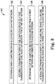
- Figure 3 is a block diagram of an example method 340 for transmission power adjustments, in accordance with the present disclosure.
- the method 340 can be performed by a computing device as described herein.
- the method 340 can be performed by a processing resource executing instructions stored on a non-transitory computer readable medium.
- the method 340 includes determining that a computing device is connected to a first network. Determining that a computing device is connected to a first network includes determining whether the computing device is connected to a particular network type. The method 340 includes querying the SSID connection of the first network. Querying the SSID connection is utilized to determine whether the computing device is connected to an infrastructure network or whether the computing device is connected to a peer to peer network.
- determining when the computing device is connected to the first network can be based on a destination address of each packet transmitted by the computing device. In some examples, determining when the computing device is connected to the second network can be based on a destination address of each packet transmitted by the computing device. For example, the destination address of the packet can indicate a type of network and based on the type of network the computing device can determine a relative distance of a first hop or docking station from the computing device. In this way, the computing device can alter the transmission power of the transmitter based on a relative distance of the first hop or docking station from the computing device.
- the method 340 includes altering a transmission power of the computing device to a first transmission power level based on a network type of the first network.
- the first transmission power level can be a power level associated with a transmitter of the computing device.
- the first transmission power level corresponds to the first network.
- the first transmission power level can be a maximum transmission power level for the transmitter when the first network is an infrastructure network.
- the method 340 includes determining that the computing device is disconnected from the first network and connected to a second network. In some examples, it can be determined that the computing device is disconnected from the first network based on a destination address of a data packet to be transmitted. For example, it can be determined when a previous data packet includes a destination address of the first network and a next data packet includes a destination address of the second network. It is determined based on querying the SSID connection of the first network and the second network.
- the method 340 includes altering the transmission power of the computing device to a second transmission power level based on a network type of the second network. As described herein, the transmission power of the computing device is altered to a second transmission power level when it is determined that the computing device is connected to the second network.
- the transmission power of the computing device can be altered data packet by data packet based on a destination address of each packet. In this way, the computing device 202 can save battery power and reduce noise for other computing devices within a particular area or environment.
Landscapes
- Engineering & Computer Science (AREA)
- Computer Networks & Wireless Communication (AREA)
- Signal Processing (AREA)
- Mobile Radio Communication Systems (AREA)
Description
- Wireless network operating systems may utilize a networking standard. For example, wireless network operating systems can utilize IEEE 802.11 standard. Wireless networks utilizing network operating systems can allow client devices to connect with access points within the wireless network. In some examples, the network can include a plurality of access points that can each receive communication requests for client devices. Relatively large quantities of client devices can send communication requests to the plurality of access points.
-
US 2013/324182 A1 discloses device-to-device, D2D, cross link power control systems and methods. For example, a device such as a UE or WTRU may determine whether it may have simultaneous transmissions where at least one of the transmissions may include a cross link transmission. The device may further determine whether a total transmit power of the simultaneous transmissions may exceed a maximum transmit power of the device. If the device may have simultaneous transmissions and such transmissions may exceed the maximum transmit power, the device may reallocate power based on a priority or priority setting. The device may further determine a maximum cross link power, a maximum device power, and a cross link transmit power level such that the device may further control the power for transmissions based thereon. -
EP 1670183 A1 discloses a system and a method for controlling transmission power in a wireless local area network, WLAN, and more particularly, a system and a method for controlling transmission power in a WLAN that are capable of providing a WLAN service to terminals outside a service area by controlling the transmission power in the WLAN. Thus, link margin data of a station positioned at a hidden node of the WLAN is received from another station positioned in a service area, and the received link margin data is compared with preset link margin data for control of the transmission power in the WLAN. -
WO 2016/062666 A2 discloses a system, a user equipment and a base station for carrier selection in a wireless telecommunication system. This document is directed towards a system for co-existence optimizations of different radio technologies in a wireless telecommunication system. In particular, it relates to technology adapted to operate according to the IEEE 802.11 family of standards, commonly known as Wi-Fi or WLAN, and technology adapted to operate in accordance with mobile communication standards such as the "Long Term Evolution", or LTE, transmission technology. - The object of the present application is solved by the independent claims. Advantageous embodiments are described by the dependent claims. Embodiments not falling under the scope of the claims should be understood as examples useful for understanding the invention.
-
-
Figure 1 illustrates an example environment for transmission power adjustments, in accordance with the present disclosure. -
Figure 2 is a block diagram of an example computing device for transmission power adjustments, in accordance with the present disclosure. -
Figure 3 is a block diagram of an example method for transmission power adjustments, in accordance with the present disclosure. - Computing devices can include transmitter to transmit wireless signals. For example, computing devices can include a transmitter to transmit radio signals to a network device (e.g., access point, router, etc.). In some examples, the computing devices can include a transmitter for WiFi connections. For example, the computing device can utilize a WiFi transmitter for connecting to a local area network, a docking station (e.g., WiFi Direct, etc.), or other type of WiFi connections.
- The transmission power of the WiFi transmitter can be set to a maximum power or relatively high power level when network devices for a local area network or WiFi connections are at a relatively large distance from the computing device. In some previous examples, the transmission power of the WiFi transmitter may not be adjustable and may be set to a highest power in order to ensure a strong connection between the computing device and the network devices as described herein. However, the highest available transmission power can provide considerable un-needed signal margin, especially in medium to short range distances between wireless devices. This un-needed margin of transmission power in areas with a greater quantity of computing devices utilizing wireless transmitters can cause signal noise that can interfere with signal quality of the computing devices within the area.
- The present disclosure utilizes an adjustable wireless transmitter (e.g., adjustable WiFi transmitter) to alter a power level of the transmitter based on a type of network utilized by the computing device. In some examples, the type of network can include a plurality of different network types with different network properties. Computing devices can connect to an infrastructure network connection or a peer to peer network connection. As used herein, an infrastructure network connection can be a local area network connection and/or similar connection that utilizes a plurality of access points to transmit signals to and receive signals from the computing device. As used herein, a peer to peer network connection can be a docking network connection that utilizes a network dock to transmit signals to and receive signals from the computing device.
- In some examples, the infrastructure network connection can utilize access points that are positioned relatively far from the computing device. In these examples, a relatively greater transmission power can be utilized to ensure a strong connection with the access points. In other examples, the peer to peer network connection can utilize a network dock or network docking station that can be positioned relatively close to the computing device. In these examples, a relatively lower transmission power can be utilized due to the relatively close proximity between the network docking station and the computing device.
- The network type is determined and the transmission power is adjusted based on the network type. For example, the transmission power can be increased to a maximum transmission power level when the computing device is connected to an infrastructure network connection and the transmission power can be decreased to a lower transmission power level when the computing device is connected to a peer to peer network connection. In this way, battery power can be reserved and noise created by the increased transmission power level can be reduced when the computing device is connected to the peer to peer network.
-
Figure 1 illustrates anexample environment 100 for transmission power adjustments, in accordance with the present disclosure. In some examples, theenvironment 100 can be a location with a relatively high density of computing devices 102-1, 102-2. For example, theenvironment 100 can include an office space with a plurality ofcubicles 114 or barriers between the plurality of computing devices 102-1, 102-2 and/or user's office space. In some examples, the plurality of computing devices 102-1, 102-2 can be laptop computers or desktop computers that are utilized by a user within theenvironment 100. - In some examples, the plurality of computing devices 102-1, 102-2 can include a corresponding transmitter 104-1, 104-2. For example, computing device 102-1 can include a transmitter 104-1 and computing device 102-2 can include a transmitter 104-2. In some examples, the transmitters 104-1, 104-2 can be wireless transmitters or radio transmitters that can transmit a radio wave or signal to a different computing device or network device. In some examples, the transmitters 104-1, 104-2 can be WiFi transmitters. For example, the transmitters 104-1, 104-2 can be WiFi certified transmitters that can include media access control (MAC) and physical layer specifications for communicating via a WiFi connection.
- In some examples, the plurality of computing devices 102-1, 102-2 can include instructions, that when executed by a processing resource, can cause the processing resource to determine a network type for a wireless connection from a plurality of network types. In some examples, the plurality of network types include a peer to
peer network connection 112 between the computing device 102-2 and a dock 108-2 and aninfrastructure network connection 110 between computing device 102-1 and aninfrastructure network 106. - In some examples, the dock 108-2 can be a device that can utilize a peer to
peer network connection 112 such as WiFi Direct or other type of peer to peer connection. In some examples, the dock 108-2 can be connected to a wired network connection (e.g., Ethernet connection, etc.) and provide network access to the computing device 102-2 via the peer topeer network connection 112. In other examples, the dock 108-2 can be a different computing device that can connect to computing device 102-2 via the peer topeer network connection 112. In some additional examples, the dock 108-2 can be a peripheral device (e.g., printer, speaker, display, etc.) that can connect to computing device 102-2 via the peer topeer network connection 112. - In some examples, the
infrastructure network 106 can be a local area network (LAN), wide area network (WAN), or other type of infrastructure network. As used herein, aninfrastructure network 106 can include hardware and/or instructions for a network that enable network connectivity, communication, operations, and/or management of an enterprise network. As described herein, theinfrastructure network 106 can utilize a plurality of access points and/or other types of hardware to connect computing devices, such as computing device 102-1, to other computing devices, databases, and/or Internet. In some examples, the hardware for theinfrastructure network 106 can be positioned at a relatively greater distance compared to a dock 108-1, 108-2. For example, a first hop of aninfrastructure network 106 can be at a greater distance from the computing device 102-1 than the dock 108-1. As used herein, a first hop of aninfrastructure network 106 can be a network device (e.g., access point, router, etc.) where a data packet from the computing device 102-1 is sent directly before being transferred to a different network device of theinfrastructure network 106. - In some examples, the computing device 102-1, 102-2 can determine the network type (e.g., peer to peer
network connection 112,infrastructure network connection 110, etc.) based on a destination address of a data packet to be transferred by the transmitter 104-1, 104-2. For example, the computing device 102-1, 102-2 can monitor data packets that are transmitted by the transmitter 104-1, 104-2 respectively. In this example, the computing device 102-1, 102-2 can determine a destination address (e.g., MAC address, etc.) for a data packet and determine whether the destination address indicates that the computing device 102-1, 102-2 is connected to a particular type of network. For example, the transmitter 104-1 of the computing device 102-1 can transmit a data packet to theinfrastructure network 106 via theinfrastructure network connection 110. In this example, the data packet can include a destination address of a first hop of theinfrastructure network 106. In this example, the computing device 102-1 can determine that it is transmitting the data packet to aninfrastructure network 106 via aninfrastructure network connection 110. - The computing device 102-1, 102-2 queries the service set identifier (SSID) of the
network connections infrastructure network connection 110 with theinfrastructure network 106. In another example, the computing device 102-2 can query the SSID of the peer to peernetwork connection 112 with the dock 108-2. The SSID of thenetwork connections - In some examples, the plurality of computing devices 102-1, 102-2 can include instructions, that when executed by a processing resource, can cause the processing resource to alter a transmission power for a transmitter 104-1, 104-2 based on the network type for the wireless connection. For example, the computing device 102-1 can alter the transmission power of the transmitter 104-1 to an increased level or a maximum level to ensure a secure connection between the computing device 102-1 and the
infrastructure network 106. In some examples, the increased transmission power can be approximately 18-20 decibel milliwatts (dBm). - In some examples, the computing device 102-2 can alter the transmission power of the transmitter 104-2 to a decreased level when the computing device 102-2 determines that a destination address of a packet indicates the computing device 102-2 is connected to a dock 108-2. For example, the destination address of a packet can indicate that the computing device 102-2 has a peer to peer
network connection 112 with the dock 108-2. In some examples, the decreased transmission power can be approximately 10 dBm. Thus, the computing device 102-1, 102-2 can alter between a first transmission power level (e.g., maximum transmission power level) for a first network type (e.g., infrastructure network connection 110) and a second transmission power level (e.g., lowered transmission power level, decreased transmission power level, etc.) for a second network type (e.g., peer to peer network connection 112). - In some examples, altering the transmission power of the transmitters 104-1, 104-2 can be performed dynamically and/or for a packet to packet transmission. For example, the computing device 102-1, 102-2 can alter a transmission power of the transmitter 104-1, 104-2 for each packet transmitted by the transmitter 104-1, 104-2. In this way, packets to be delivered to the
infrastructure network 106 can be transmitted at a relatively higher transmission power and packets to be delivered to the dock 108-1, 108-2 can be transmitted at a relatively lower transmission power. As described herein, decreasing or lowering the transmission power of a transmitter 104-1, 104-2 can save batter power for the computing device 102-1, 102-2 respectively. In addition, decreasing or lowering the transmission power of a transmitter 104-1, 104-2 can decrease noise created by multiple transmitters 104-1, 104-2 within theenvironment 100. -
Figure 2 is a block diagram of anexample computing device 202 for transmission power adjustments, in accordance with the present disclosure. In some examples, thecomputing device 202 can be a laptop computer or portable computing device as referenced inFigure 1 . In some examples, thecomputing device 202 can include amemory resource 224 that can be utilized to storeinstructions processing resource 220 to perform functions described herein. - A
processing resource 220 may be a central processing unit (CPU), microprocessor, and/or other hardware device suitable for retrieval and execution of instructions stored inmemory resource 224. In the particular example shown inFigure 2 ,processing resource 220 may receive, determine, and sendinstructions instructions processing resource 220 may include an electronic circuit comprising a number of electronic components for performing the operations of theinstructions memory resource 224. With respect to the executable instruction representations or boxes described and shown herein, it should be understood that part or all of theexecutable instructions -
Memory resource 224 may be any electronic, magnetic, optical, or other physical storage device that storesexecutable instructions memory resource 224 may be, for example, Random Access Memory (RAM), an Electrically-Erasable Programmable Read-Only Memory (EEPROM), a storage drive, an optical disc, and the like. Theexecutable instructions memory resource 224.Memory resource 224 may be a portable, external or remote storage medium, for example, that allows a system to download theinstructions executable instructions memory resource 224 may be encoded withexecutable instructions - The
computing device 202 may includeinstructions 226 executable by aprocessing resource 220, to monitor a destination address of a data packet to be transmitted by a device. As described herein, a destination address of a data packet can include a MAC address that indicates a network device or other type of device that will receive the data packet. In some examples, the destination address can be utilized to determine whether thecomputing device 202 is connected to an infrastructure network or a peer to peer network as described herein. - The
computing device 202 may includeinstructions 228 executable by aprocessing resource 220, to alter a WIFI transmission power of the device to a first transmission power level when the destination address indicates a peer to peer network connection is to be utilized by the device. In some examples, the WIFI transmission power can be altered to the first transmission power level when the destination address of the data packet indicates the data packet is being transmitted to a dock (e.g., docking station, dock 108-1, 108-2, etc.). In some examples, the first transmission power level can be a relatively lower transmission power level. For example, the first transmission power level can be approximately 10 dBm compared to a maximum transmission power level or a second transmission power level that can be between 18-20 dBm. - The
computing device 202 may includeinstructions 230 executable by aprocessing resource 220, to alter the WIFI transmission power of the device to a second transmission power level when the destination address indicates an infrastructure network connection is to be utilized by the device. As described herein, the destination address can indicate that a data packet is to be transmitted to a network device or first hop network device of an infrastructure network. In some examples, the second transmission power level can be a maximum transmission power level for the computing device. For example, the first transmission power level can be lower than the second transmission power level. - As described herein, the
computing device 202 can alter the WIFI transmission power of a transmitter for each packet transmitted by thecomputing device 202. For example, thecomputing device 202 can determine a destination address for each packet transmitted by a transmitter of thecomputing device 202 and alter the WIFI transmission power of the transmitter prior to transmitting each data packet. In this way, thecomputing device 202 can save battery power and reduce noise for other computing devices within a particular area or environment. -
Figure 3 is a block diagram of anexample method 340 for transmission power adjustments, in accordance with the present disclosure. In some examples, themethod 340 can be performed by a computing device as described herein. For example, themethod 340 can be performed by a processing resource executing instructions stored on a non-transitory computer readable medium. - At
box 342, themethod 340 includes determining that a computing device is connected to a first network. Determining that a computing device is connected to a first network includes determining whether the computing device is connected to a particular network type. Themethod 340 includes querying the SSID connection of the first network. Querying the SSID connection is utilized to determine whether the computing device is connected to an infrastructure network or whether the computing device is connected to a peer to peer network. - In some examples, determining when the computing device is connected to the first network can be based on a destination address of each packet transmitted by the computing device. In some examples, determining when the computing device is connected to the second network can be based on a destination address of each packet transmitted by the computing device. For example, the destination address of the packet can indicate a type of network and based on the type of network the computing device can determine a relative distance of a first hop or docking station from the computing device. In this way, the computing device can alter the transmission power of the transmitter based on a relative distance of the first hop or docking station from the computing device.
- At box 344, the
method 340 includes altering a transmission power of the computing device to a first transmission power level based on a network type of the first network. In some examples, the first transmission power level can be a power level associated with a transmitter of the computing device. The first transmission power level corresponds to the first network. For example, the first transmission power level can be a maximum transmission power level for the transmitter when the first network is an infrastructure network. - At
box 346, themethod 340 includes determining that the computing device is disconnected from the first network and connected to a second network. In some examples, it can be determined that the computing device is disconnected from the first network based on a destination address of a data packet to be transmitted. For example, it can be determined when a previous data packet includes a destination address of the first network and a next data packet includes a destination address of the second network. It is determined based on querying the SSID connection of the first network and the second network. - At box 348, the
method 340 includes altering the transmission power of the computing device to a second transmission power level based on a network type of the second network. As described herein, the transmission power of the computing device is altered to a second transmission power level when it is determined that the computing device is connected to the second network. - In some examples, the transmission power of the computing device can be altered data packet by data packet based on a destination address of each packet. In this way, the
computing device 202 can save battery power and reduce noise for other computing devices within a particular area or environment. - In the foregoing detailed description of the present disclosure, reference is made to the accompanying drawings that form a part hereof, and in which is shown by way of illustration how examples of the disclosure may be practiced. These examples are described in sufficient detail to enable those of ordinary skill in the art to practice the examples of this disclosure, and it is to be understood that other examples may be utilized and that process, electrical, and/or structural changes may be made without departing from the scope of the present disclosure.
- The figures herein follow a numbering convention in which the first digit corresponds to the drawing figure number and the remaining digits identify an element or component in the drawing. Elements shown in the various figures herein can be added, exchanged, and/or eliminated so as to provide a number of additional examples of the present disclosure. In addition, the proportion and the relative scale of the elements provided in the figures are intended to illustrate the examples of the present disclosure, and should not be taken in a limiting sense. As used herein, the designator "N", particularly with respect to reference numerals in the drawings, indicates that a number of the particular feature so designated can be included with examples of the present disclosure. The designators can represent the same or different numbers of the particular features. Further, as used herein, "a number of" an element and/or feature can refer to one or more of such elements and/or features.
Claims (6)
- A method (340), comprising:determining (342) that a computing device (102-1, 102-2, 202) is connected to a first network;altering (344) a transmission power of the computing device (102-1, 102-2, 202) to a first transmission power level based on a network type of the first network;determining (346) that the computing device (102-1, 102-2, 202) is disconnected from the first network and connected to a second network;altering (348) the transmission power of the computing device (102-1, 102-2, 202) to a second transmission power level based on a network type of the second network, wherein the network type of the first network is an infrastructure network connection (110) and the network type of the second network is a peer to peer network connection (112); andquerying a service set identifier, SSID, connection of the first network,wherein determining that the computing device (102-1, 102-2, 202) is connected to the first network is based on querying the SSID connection of the first network.
- The method (340) of claim 1, wherein determining that the computing device (102-1, 102-2, 202) is connected to the first network and the second network is based on a destination address of each packet transmitted by the computing device (102-1, 102-2, 202).
- The method of claim 1, wherein the peer to peer network connection (112) is a wireless connection between the computing device (102-1, 102-2, 202) and a docking station (108-1, 108-2).
- The method of claim 3, wherein the wireless connection is a WiFi connection.
- The method of one of claims 1 to 4, wherein the first transmission power level is higher than the second transmission power level.
- A non-transitory machine readable medium including instructions which, when executed by a processing resource (220), cause the processing resource (220) to carry out the method of any one of claims 1 to 5.
Applications Claiming Priority (1)
| Application Number | Priority Date | Filing Date | Title |
|---|---|---|---|
| PCT/US2017/041519 WO2019013765A1 (en) | 2017-07-11 | 2017-07-11 | Transmission power adjustments |
Publications (3)
| Publication Number | Publication Date |
|---|---|
| EP3556152A1 EP3556152A1 (en) | 2019-10-23 |
| EP3556152A4 EP3556152A4 (en) | 2020-08-12 |
| EP3556152B1 true EP3556152B1 (en) | 2021-06-30 |
Family
ID=65002316
Family Applications (1)
| Application Number | Title | Priority Date | Filing Date |
|---|---|---|---|
| EP17917815.7A Active EP3556152B1 (en) | 2017-07-11 | 2017-07-11 | Transmission power adjustments |
Country Status (5)
| Country | Link |
|---|---|
| US (1) | US11228989B2 (en) |
| EP (1) | EP3556152B1 (en) |
| CN (1) | CN110235480B (en) |
| TW (1) | TWI741189B (en) |
| WO (1) | WO2019013765A1 (en) |
Family Cites Families (26)
| Publication number | Priority date | Publication date | Assignee | Title |
|---|---|---|---|---|
| US7583975B2 (en) | 2004-03-08 | 2009-09-01 | Intel Corporation | Adaptive transmit power control in wireless devices |
| US7424626B2 (en) * | 2004-04-28 | 2008-09-09 | Hewlett-Packard Development Company, L.P. | Laptop computer recharging using Ethernet connection |
| KR100582727B1 (en) * | 2004-12-08 | 2006-05-22 | 삼성전자주식회사 | Transmit power control system and method in wireless lan |
| ES2427814T3 (en) * | 2005-11-11 | 2013-11-04 | Telefonaktiebolaget L M Ericsson (Publ) | Method and apparatus to limit peer communication interference |
| CN101925167A (en) | 2009-06-09 | 2010-12-22 | 中兴通讯股份有限公司 | Power control method and device of wireless local area network access point device |
| US8830849B2 (en) * | 2010-01-11 | 2014-09-09 | Qualcomm Incorporated | Method and apparatus for detecting transmission signals |
| CN101951671B (en) | 2010-08-25 | 2013-01-16 | 华为终端有限公司 | Wireless network connection method, device and terminal |
| KR101755264B1 (en) * | 2010-11-04 | 2017-07-10 | 인터디지탈 패튼 홀딩스, 인크 | Method and apparatus for establishing peer-to-peer communication |
| US9043618B2 (en) * | 2011-06-17 | 2015-05-26 | Hewlett-Packard Development Company, L.P. | Drawing power over network cable |
| US8533500B2 (en) * | 2011-06-30 | 2013-09-10 | Hewlett-Packard Development Company, L.P. | Providing power to a communication device via a device switch |
| US9332505B2 (en) * | 2011-11-11 | 2016-05-03 | Telefonaktiebolaget L M Ericsson (Publ) | Methods and apparatus for performing measurements in adaptive downlink power transmission |
| CN109890074A (en) * | 2012-05-31 | 2019-06-14 | 交互数字专利控股公司 | Device-to-device (D2D) cross link power control |
| CN102740428B (en) * | 2012-06-20 | 2015-04-15 | 华为技术有限公司 | Method for regulating and controlling transmitting power and wireless router equipment |
| CN103686954A (en) | 2012-09-24 | 2014-03-26 | 中兴通讯股份有限公司 | Device and method for saving electricity used by WIFI |
| CN104995937B (en) | 2013-03-15 | 2019-03-22 | 英特尔公司 | Downlink power management |
| CN104105186B (en) * | 2013-04-03 | 2018-03-02 | 电信科学技术研究院 | A kind of method, apparatus and system for carrying out Power Control |
| GB2520385B (en) * | 2013-04-17 | 2021-01-27 | Pismo Labs Technology Ltd | Methods and systems for supplying and receiving power over Ethernet |
| US9300342B2 (en) | 2013-04-18 | 2016-03-29 | Apple Inc. | Wireless device with dynamically adjusted maximum transmit powers |
| US9820162B2 (en) | 2014-01-24 | 2017-11-14 | Mediatek Singapore Pte Ltd. | Adaptive CCA and TX power level adjustment for dense deployment of wireless networks |
| KR102301828B1 (en) | 2014-05-02 | 2021-09-14 | 삼성전자 주식회사 | Method and apparatus for real time transmission power control in wireless communication system |
| CN104039001B (en) * | 2014-06-27 | 2018-10-12 | 联想(北京)有限公司 | Poewr control method and power control device |
| CN104270806B (en) * | 2014-09-11 | 2017-12-05 | 小米科技有限责任公司 | Transmission power adjustment method and device |
| US20170238319A1 (en) * | 2014-10-20 | 2017-08-17 | Ipcom Gmbh & Co. Kg | System, user equipment and base station for carrier selection in a wireless telecommunication system |
| CN105813186B (en) * | 2014-12-31 | 2019-11-22 | 上海诺基亚贝尔股份有限公司 | A kind of method, apparatus and system determining transmission power for user equipment |
| WO2017027055A1 (en) * | 2015-08-10 | 2017-02-16 | Intel IP Corporation | Enhanced sounding reference signaling for uplink beam tracking |
| CN105376357B (en) * | 2015-09-30 | 2019-04-05 | 青岛海信移动通信技术股份有限公司 | A kind of antenna installation method and device of mobile device |
-
2017
- 2017-07-11 WO PCT/US2017/041519 patent/WO2019013765A1/en unknown
- 2017-07-11 US US16/076,211 patent/US11228989B2/en active Active
- 2017-07-11 CN CN201780085069.0A patent/CN110235480B/en active Active
- 2017-07-11 EP EP17917815.7A patent/EP3556152B1/en active Active
-
2018
- 2018-06-05 TW TW107119342A patent/TWI741189B/en active
Also Published As
| Publication number | Publication date |
|---|---|
| EP3556152A1 (en) | 2019-10-23 |
| CN110235480B (en) | 2022-12-02 |
| TW201909674A (en) | 2019-03-01 |
| TWI741189B (en) | 2021-10-01 |
| WO2019013765A1 (en) | 2019-01-17 |
| US20210204228A1 (en) | 2021-07-01 |
| EP3556152A4 (en) | 2020-08-12 |
| CN110235480A (en) | 2019-09-13 |
| US11228989B2 (en) | 2022-01-18 |
Similar Documents
| Publication | Publication Date | Title |
|---|---|---|
| US10129878B2 (en) | Systems and methods for dynamic band switching | |
| WO2021243580A1 (en) | Method and apparatus for transmitting downlink positioning reference signal, and storage medium | |
| US9622269B2 (en) | Optimizing the use of shared radio frequency medium using intelligent suppression of probe request frames | |
| US20210212150A1 (en) | Method and apparatus for multi-link operations | |
| US10554795B2 (en) | Uplink transmission method, related device, and system | |
| US11190951B2 (en) | Method and apparatus for dimensioning base stations and determining spectrum availability in a spectrum controlled network | |
| JP2006524958A (en) | Wireless local area network system with self-configuration and self-optimization | |
| WO2018173418A1 (en) | Device, method, and recording medium | |
| EP3662720B1 (en) | Cellular dual connectivity setup | |
| CN110461033B (en) | Receive operation mode indication for power saving | |
| CN109151955B (en) | Communication method and device | |
| KR20160150605A (en) | Method and apparatus for operation in coexistence environment of cellular, non-cellular, macro and micro networks | |
| KR20150105433A (en) | Communication control method, user equipment, network server, and system | |
| EP3120624B1 (en) | Method and apparatus for positioning measurement management | |
| US20160050614A1 (en) | Method and device for configuring multi-band based link in wireless lan system | |
| US8989754B2 (en) | Systems and method for BT AMP and WLAN concurrency | |
| EP3556152B1 (en) | Transmission power adjustments | |
| EP3383129B1 (en) | Master-slave type network-based method and apparatus for selecting management frame antenna | |
| KR20230125844A (en) | Random access including sending or receiving Msg3 messages | |
| WO2020020273A1 (en) | Method for connecting antenna device with base station, antenna device and base station | |
| KR20170137347A (en) | Method and apparatus for dynamic connection change in wlan | |
| KR101702826B1 (en) | Method for managing a wireless environment configuration of ap using ac | |
| WO2024031570A1 (en) | Csi-rs resource configuration method and apparatus, and device and medium | |
| KR20230066331A (en) | Communication method and device | |
| Ševerenka | Wireless network implementation in Pabiržis |
Legal Events
| Date | Code | Title | Description |
|---|---|---|---|
| STAA | Information on the status of an ep patent application or granted ep patent |
Free format text: STATUS: THE INTERNATIONAL PUBLICATION HAS BEEN MADE |
|
| PUAI | Public reference made under article 153(3) epc to a published international application that has entered the european phase |
Free format text: ORIGINAL CODE: 0009012 |
|
| STAA | Information on the status of an ep patent application or granted ep patent |
Free format text: STATUS: REQUEST FOR EXAMINATION WAS MADE |
|
| 17P | Request for examination filed |
Effective date: 20190716 |
|
| AK | Designated contracting states |
Kind code of ref document: A1 Designated state(s): AL AT BE BG CH CY CZ DE DK EE ES FI FR GB GR HR HU IE IS IT LI LT LU LV MC MK MT NL NO PL PT RO RS SE SI SK SM TR |
|
| AX | Request for extension of the european patent |
Extension state: BA ME |
|
| REG | Reference to a national code |
Ref country code: DE Ref legal event code: R079 Ref document number: 602017041481 Country of ref document: DE Free format text: PREVIOUS MAIN CLASS: H04W0052180000 Ipc: H04W0052400000 |
|
| A4 | Supplementary search report drawn up and despatched |
Effective date: 20200714 |
|
| RIC1 | Information provided on ipc code assigned before grant |
Ipc: H04W 52/28 20090101ALI20200708BHEP Ipc: H04W 52/40 20090101AFI20200708BHEP Ipc: H04W 52/38 20090101ALI20200708BHEP Ipc: H04W 52/44 20090101ALI20200708BHEP |
|
| DAV | Request for validation of the european patent (deleted) | ||
| DAX | Request for extension of the european patent (deleted) | ||
| GRAP | Despatch of communication of intention to grant a patent |
Free format text: ORIGINAL CODE: EPIDOSNIGR1 |
|
| STAA | Information on the status of an ep patent application or granted ep patent |
Free format text: STATUS: GRANT OF PATENT IS INTENDED |
|
| INTG | Intention to grant announced |
Effective date: 20210407 |
|
| GRAS | Grant fee paid |
Free format text: ORIGINAL CODE: EPIDOSNIGR3 |
|
| GRAA | (expected) grant |
Free format text: ORIGINAL CODE: 0009210 |
|
| STAA | Information on the status of an ep patent application or granted ep patent |
Free format text: STATUS: THE PATENT HAS BEEN GRANTED |
|
| AK | Designated contracting states |
Kind code of ref document: B1 Designated state(s): AL AT BE BG CH CY CZ DE DK EE ES FI FR GB GR HR HU IE IS IT LI LT LU LV MC MK MT NL NO PL PT RO RS SE SI SK SM TR |
|
| REG | Reference to a national code |
Ref country code: CH Ref legal event code: EP |
|
| REG | Reference to a national code |
Ref country code: AT Ref legal event code: REF Ref document number: 1407577 Country of ref document: AT Kind code of ref document: T Effective date: 20210715 |
|
| REG | Reference to a national code |
Ref country code: DE Ref legal event code: R096 Ref document number: 602017041481 Country of ref document: DE |
|
| REG | Reference to a national code |
Ref country code: IE Ref legal event code: FG4D |
|
| REG | Reference to a national code |
Ref country code: LT Ref legal event code: MG9D |
|
| PG25 | Lapsed in a contracting state [announced via postgrant information from national office to epo] |
Ref country code: FI Free format text: LAPSE BECAUSE OF FAILURE TO SUBMIT A TRANSLATION OF THE DESCRIPTION OR TO PAY THE FEE WITHIN THE PRESCRIBED TIME-LIMIT Effective date: 20210630 Ref country code: BG Free format text: LAPSE BECAUSE OF FAILURE TO SUBMIT A TRANSLATION OF THE DESCRIPTION OR TO PAY THE FEE WITHIN THE PRESCRIBED TIME-LIMIT Effective date: 20210930 Ref country code: HR Free format text: LAPSE BECAUSE OF FAILURE TO SUBMIT A TRANSLATION OF THE DESCRIPTION OR TO PAY THE FEE WITHIN THE PRESCRIBED TIME-LIMIT Effective date: 20210630 |
|
| REG | Reference to a national code |
Ref country code: NL Ref legal event code: MP Effective date: 20210630 |
|
| REG | Reference to a national code |
Ref country code: AT Ref legal event code: MK05 Ref document number: 1407577 Country of ref document: AT Kind code of ref document: T Effective date: 20210630 |
|
| PG25 | Lapsed in a contracting state [announced via postgrant information from national office to epo] |
Ref country code: SE Free format text: LAPSE BECAUSE OF FAILURE TO SUBMIT A TRANSLATION OF THE DESCRIPTION OR TO PAY THE FEE WITHIN THE PRESCRIBED TIME-LIMIT Effective date: 20210630 Ref country code: RS Free format text: LAPSE BECAUSE OF FAILURE TO SUBMIT A TRANSLATION OF THE DESCRIPTION OR TO PAY THE FEE WITHIN THE PRESCRIBED TIME-LIMIT Effective date: 20210630 Ref country code: NO Free format text: LAPSE BECAUSE OF FAILURE TO SUBMIT A TRANSLATION OF THE DESCRIPTION OR TO PAY THE FEE WITHIN THE PRESCRIBED TIME-LIMIT Effective date: 20210930 Ref country code: LV Free format text: LAPSE BECAUSE OF FAILURE TO SUBMIT A TRANSLATION OF THE DESCRIPTION OR TO PAY THE FEE WITHIN THE PRESCRIBED TIME-LIMIT Effective date: 20210630 Ref country code: GR Free format text: LAPSE BECAUSE OF FAILURE TO SUBMIT A TRANSLATION OF THE DESCRIPTION OR TO PAY THE FEE WITHIN THE PRESCRIBED TIME-LIMIT Effective date: 20211001 |
|
| PG25 | Lapsed in a contracting state [announced via postgrant information from national office to epo] |
Ref country code: EE Free format text: LAPSE BECAUSE OF FAILURE TO SUBMIT A TRANSLATION OF THE DESCRIPTION OR TO PAY THE FEE WITHIN THE PRESCRIBED TIME-LIMIT Effective date: 20210630 Ref country code: ES Free format text: LAPSE BECAUSE OF FAILURE TO SUBMIT A TRANSLATION OF THE DESCRIPTION OR TO PAY THE FEE WITHIN THE PRESCRIBED TIME-LIMIT Effective date: 20210630 Ref country code: SK Free format text: LAPSE BECAUSE OF FAILURE TO SUBMIT A TRANSLATION OF THE DESCRIPTION OR TO PAY THE FEE WITHIN THE PRESCRIBED TIME-LIMIT Effective date: 20210630 Ref country code: SM Free format text: LAPSE BECAUSE OF FAILURE TO SUBMIT A TRANSLATION OF THE DESCRIPTION OR TO PAY THE FEE WITHIN THE PRESCRIBED TIME-LIMIT Effective date: 20210630 Ref country code: AT Free format text: LAPSE BECAUSE OF FAILURE TO SUBMIT A TRANSLATION OF THE DESCRIPTION OR TO PAY THE FEE WITHIN THE PRESCRIBED TIME-LIMIT Effective date: 20210630 Ref country code: CZ Free format text: LAPSE BECAUSE OF FAILURE TO SUBMIT A TRANSLATION OF THE DESCRIPTION OR TO PAY THE FEE WITHIN THE PRESCRIBED TIME-LIMIT Effective date: 20210630 Ref country code: PT Free format text: LAPSE BECAUSE OF FAILURE TO SUBMIT A TRANSLATION OF THE DESCRIPTION OR TO PAY THE FEE WITHIN THE PRESCRIBED TIME-LIMIT Effective date: 20211102 Ref country code: RO Free format text: LAPSE BECAUSE OF FAILURE TO SUBMIT A TRANSLATION OF THE DESCRIPTION OR TO PAY THE FEE WITHIN THE PRESCRIBED TIME-LIMIT Effective date: 20210630 Ref country code: NL Free format text: LAPSE BECAUSE OF FAILURE TO SUBMIT A TRANSLATION OF THE DESCRIPTION OR TO PAY THE FEE WITHIN THE PRESCRIBED TIME-LIMIT Effective date: 20210630 |
|
| PG25 | Lapsed in a contracting state [announced via postgrant information from national office to epo] |
Ref country code: PL Free format text: LAPSE BECAUSE OF FAILURE TO SUBMIT A TRANSLATION OF THE DESCRIPTION OR TO PAY THE FEE WITHIN THE PRESCRIBED TIME-LIMIT Effective date: 20210630 |
|
| REG | Reference to a national code |
Ref country code: CH Ref legal event code: PL |
|
| REG | Reference to a national code |
Ref country code: DE Ref legal event code: R097 Ref document number: 602017041481 Country of ref document: DE |
|
| PG25 | Lapsed in a contracting state [announced via postgrant information from national office to epo] |
Ref country code: MC Free format text: LAPSE BECAUSE OF FAILURE TO SUBMIT A TRANSLATION OF THE DESCRIPTION OR TO PAY THE FEE WITHIN THE PRESCRIBED TIME-LIMIT Effective date: 20210630 |
|
| REG | Reference to a national code |
Ref country code: BE Ref legal event code: MM Effective date: 20210731 |
|
| PG25 | Lapsed in a contracting state [announced via postgrant information from national office to epo] |
Ref country code: LI Free format text: LAPSE BECAUSE OF NON-PAYMENT OF DUE FEES Effective date: 20210731 Ref country code: DK Free format text: LAPSE BECAUSE OF FAILURE TO SUBMIT A TRANSLATION OF THE DESCRIPTION OR TO PAY THE FEE WITHIN THE PRESCRIBED TIME-LIMIT Effective date: 20210630 Ref country code: CH Free format text: LAPSE BECAUSE OF NON-PAYMENT OF DUE FEES Effective date: 20210731 |
|
| PLBE | No opposition filed within time limit |
Free format text: ORIGINAL CODE: 0009261 |
|
| STAA | Information on the status of an ep patent application or granted ep patent |
Free format text: STATUS: NO OPPOSITION FILED WITHIN TIME LIMIT |
|
| PG25 | Lapsed in a contracting state [announced via postgrant information from national office to epo] |
Ref country code: LU Free format text: LAPSE BECAUSE OF NON-PAYMENT OF DUE FEES Effective date: 20210711 Ref country code: AL Free format text: LAPSE BECAUSE OF FAILURE TO SUBMIT A TRANSLATION OF THE DESCRIPTION OR TO PAY THE FEE WITHIN THE PRESCRIBED TIME-LIMIT Effective date: 20210630 |
|
| 26N | No opposition filed |
Effective date: 20220331 |
|
| PG25 | Lapsed in a contracting state [announced via postgrant information from national office to epo] |
Ref country code: IT Free format text: LAPSE BECAUSE OF FAILURE TO SUBMIT A TRANSLATION OF THE DESCRIPTION OR TO PAY THE FEE WITHIN THE PRESCRIBED TIME-LIMIT Effective date: 20210630 Ref country code: IE Free format text: LAPSE BECAUSE OF NON-PAYMENT OF DUE FEES Effective date: 20210711 Ref country code: FR Free format text: LAPSE BECAUSE OF NON-PAYMENT OF DUE FEES Effective date: 20210830 Ref country code: BE Free format text: LAPSE BECAUSE OF NON-PAYMENT OF DUE FEES Effective date: 20210731 |
|
| PG25 | Lapsed in a contracting state [announced via postgrant information from national office to epo] |
Ref country code: LT Free format text: LAPSE BECAUSE OF FAILURE TO SUBMIT A TRANSLATION OF THE DESCRIPTION OR TO PAY THE FEE WITHIN THE PRESCRIBED TIME-LIMIT Effective date: 20210630 |
|
| PG25 | Lapsed in a contracting state [announced via postgrant information from national office to epo] |
Ref country code: CY Free format text: LAPSE BECAUSE OF FAILURE TO SUBMIT A TRANSLATION OF THE DESCRIPTION OR TO PAY THE FEE WITHIN THE PRESCRIBED TIME-LIMIT Effective date: 20210630 |
|
| PG25 | Lapsed in a contracting state [announced via postgrant information from national office to epo] |
Ref country code: HU Free format text: LAPSE BECAUSE OF FAILURE TO SUBMIT A TRANSLATION OF THE DESCRIPTION OR TO PAY THE FEE WITHIN THE PRESCRIBED TIME-LIMIT; INVALID AB INITIO Effective date: 20170711 |
|
| PGFP | Annual fee paid to national office [announced via postgrant information from national office to epo] |
Ref country code: GB Payment date: 20230620 Year of fee payment: 7 |
|
| PGFP | Annual fee paid to national office [announced via postgrant information from national office to epo] |
Ref country code: DE Payment date: 20230620 Year of fee payment: 7 |
|
| PG25 | Lapsed in a contracting state [announced via postgrant information from national office to epo] |
Ref country code: MK Free format text: LAPSE BECAUSE OF FAILURE TO SUBMIT A TRANSLATION OF THE DESCRIPTION OR TO PAY THE FEE WITHIN THE PRESCRIBED TIME-LIMIT Effective date: 20210630 |