EP3554341B1 - Retrospective gating of mri - Google Patents
Retrospective gating of mri Download PDFInfo
- Publication number
- EP3554341B1 EP3554341B1 EP17825151.8A EP17825151A EP3554341B1 EP 3554341 B1 EP3554341 B1 EP 3554341B1 EP 17825151 A EP17825151 A EP 17825151A EP 3554341 B1 EP3554341 B1 EP 3554341B1
- Authority
- EP
- European Patent Office
- Prior art keywords
- gating
- time
- imaging
- navigator
- gated
- Prior art date
- Legal status (The legal status is an assumption and is not a legal conclusion. Google has not performed a legal analysis and makes no representation as to the accuracy of the status listed.)
- Active
Links
- 238000003384 imaging method Methods 0.000 claims description 95
- 230000033001 locomotion Effects 0.000 claims description 60
- 230000000241 respiratory effect Effects 0.000 claims description 36
- 238000001208 nuclear magnetic resonance pulse sequence Methods 0.000 claims description 27
- 230000000747 cardiac effect Effects 0.000 claims description 18
- 230000001351 cycling effect Effects 0.000 claims description 9
- 230000010363 phase shift Effects 0.000 claims description 6
- 210000000115 thoracic cavity Anatomy 0.000 claims description 6
- 210000000056 organ Anatomy 0.000 claims 2
- 230000029058 respiratory gaseous exchange Effects 0.000 description 12
- 210000001835 viscera Anatomy 0.000 description 7
- 238000013459 approach Methods 0.000 description 6
- 238000000034 method Methods 0.000 description 6
- 230000035479 physiological effects, processes and functions Effects 0.000 description 6
- 230000008901 benefit Effects 0.000 description 5
- 210000004185 liver Anatomy 0.000 description 4
- 238000002595 magnetic resonance imaging Methods 0.000 description 4
- 230000003287 optical effect Effects 0.000 description 4
- 230000004048 modification Effects 0.000 description 3
- 238000012986 modification Methods 0.000 description 3
- 238000012544 monitoring process Methods 0.000 description 3
- 230000004075 alteration Effects 0.000 description 2
- 230000010351 cardiac pulsation Effects 0.000 description 2
- 210000000038 chest Anatomy 0.000 description 2
- 238000002059 diagnostic imaging Methods 0.000 description 2
- 238000005259 measurement Methods 0.000 description 2
- 238000013186 photoplethysmography Methods 0.000 description 2
- 238000012545 processing Methods 0.000 description 2
- 210000000596 ventricular septum Anatomy 0.000 description 2
- 210000003484 anatomy Anatomy 0.000 description 1
- 238000002583 angiography Methods 0.000 description 1
- 210000001367 artery Anatomy 0.000 description 1
- 230000003190 augmentative effect Effects 0.000 description 1
- 238000010009 beating Methods 0.000 description 1
- 230000036772 blood pressure Effects 0.000 description 1
- 230000008602 contraction Effects 0.000 description 1
- 230000002596 correlated effect Effects 0.000 description 1
- 230000000875 corresponding effect Effects 0.000 description 1
- 230000007423 decrease Effects 0.000 description 1
- 238000010586 diagram Methods 0.000 description 1
- 238000003708 edge detection Methods 0.000 description 1
- 230000000694 effects Effects 0.000 description 1
- 230000005284 excitation Effects 0.000 description 1
- 210000002216 heart Anatomy 0.000 description 1
- 238000010191 image analysis Methods 0.000 description 1
- 239000003550 marker Substances 0.000 description 1
- 230000002107 myocardial effect Effects 0.000 description 1
- 210000004165 myocardium Anatomy 0.000 description 1
- 230000000737 periodic effect Effects 0.000 description 1
- 230000035790 physiological processes and functions Effects 0.000 description 1
- 230000008569 process Effects 0.000 description 1
- 238000012216 screening Methods 0.000 description 1
- 230000011218 segmentation Effects 0.000 description 1
- 239000007787 solid Substances 0.000 description 1
- 230000008685 targeting Effects 0.000 description 1
- 210000001519 tissue Anatomy 0.000 description 1
- 230000001960 triggered effect Effects 0.000 description 1
- 210000003462 vein Anatomy 0.000 description 1
Images
Classifications
-
- A—HUMAN NECESSITIES
- A61—MEDICAL OR VETERINARY SCIENCE; HYGIENE
- A61B—DIAGNOSIS; SURGERY; IDENTIFICATION
- A61B5/00—Measuring for diagnostic purposes; Identification of persons
- A61B5/72—Signal processing specially adapted for physiological signals or for diagnostic purposes
- A61B5/7271—Specific aspects of physiological measurement analysis
- A61B5/7285—Specific aspects of physiological measurement analysis for synchronising or triggering a physiological measurement or image acquisition with a physiological event or waveform, e.g. an ECG signal
- A61B5/7292—Prospective gating, i.e. predicting the occurrence of a physiological event for use as a synchronisation signal
-
- A—HUMAN NECESSITIES
- A61—MEDICAL OR VETERINARY SCIENCE; HYGIENE
- A61B—DIAGNOSIS; SURGERY; IDENTIFICATION
- A61B5/00—Measuring for diagnostic purposes; Identification of persons
- A61B5/05—Detecting, measuring or recording for diagnosis by means of electric currents or magnetic fields; Measuring using microwaves or radio waves
- A61B5/055—Detecting, measuring or recording for diagnosis by means of electric currents or magnetic fields; Measuring using microwaves or radio waves involving electronic [EMR] or nuclear [NMR] magnetic resonance, e.g. magnetic resonance imaging
-
- A—HUMAN NECESSITIES
- A61—MEDICAL OR VETERINARY SCIENCE; HYGIENE
- A61B—DIAGNOSIS; SURGERY; IDENTIFICATION
- A61B5/00—Measuring for diagnostic purposes; Identification of persons
- A61B5/72—Signal processing specially adapted for physiological signals or for diagnostic purposes
- A61B5/7271—Specific aspects of physiological measurement analysis
- A61B5/7282—Event detection, e.g. detecting unique waveforms indicative of a medical condition
-
- A—HUMAN NECESSITIES
- A61—MEDICAL OR VETERINARY SCIENCE; HYGIENE
- A61B—DIAGNOSIS; SURGERY; IDENTIFICATION
- A61B5/00—Measuring for diagnostic purposes; Identification of persons
- A61B5/72—Signal processing specially adapted for physiological signals or for diagnostic purposes
- A61B5/7271—Specific aspects of physiological measurement analysis
- A61B5/7285—Specific aspects of physiological measurement analysis for synchronising or triggering a physiological measurement or image acquisition with a physiological event or waveform, e.g. an ECG signal
- A61B5/7289—Retrospective gating, i.e. associating measured signals or images with a physiological event after the actual measurement or image acquisition, e.g. by simultaneously recording an additional physiological signal during the measurement or image acquisition
-
- G—PHYSICS
- G01—MEASURING; TESTING
- G01R—MEASURING ELECTRIC VARIABLES; MEASURING MAGNETIC VARIABLES
- G01R33/00—Arrangements or instruments for measuring magnetic variables
- G01R33/20—Arrangements or instruments for measuring magnetic variables involving magnetic resonance
- G01R33/44—Arrangements or instruments for measuring magnetic variables involving magnetic resonance using nuclear magnetic resonance [NMR]
- G01R33/48—NMR imaging systems
- G01R33/54—Signal processing systems, e.g. using pulse sequences ; Generation or control of pulse sequences; Operator console
- G01R33/56—Image enhancement or correction, e.g. subtraction or averaging techniques, e.g. improvement of signal-to-noise ratio and resolution
- G01R33/567—Image enhancement or correction, e.g. subtraction or averaging techniques, e.g. improvement of signal-to-noise ratio and resolution gated by physiological signals, i.e. synchronization of acquired MR data with periodical motion of an object of interest, e.g. monitoring or triggering system for cardiac or respiratory gating
- G01R33/5673—Gating or triggering based on a physiological signal other than an MR signal, e.g. ECG gating or motion monitoring using optical systems for monitoring the motion of a fiducial marker
-
- G—PHYSICS
- G01—MEASURING; TESTING
- G01R—MEASURING ELECTRIC VARIABLES; MEASURING MAGNETIC VARIABLES
- G01R33/00—Arrangements or instruments for measuring magnetic variables
- G01R33/20—Arrangements or instruments for measuring magnetic variables involving magnetic resonance
- G01R33/44—Arrangements or instruments for measuring magnetic variables involving magnetic resonance using nuclear magnetic resonance [NMR]
- G01R33/48—NMR imaging systems
- G01R33/54—Signal processing systems, e.g. using pulse sequences ; Generation or control of pulse sequences; Operator console
- G01R33/56—Image enhancement or correction, e.g. subtraction or averaging techniques, e.g. improvement of signal-to-noise ratio and resolution
- G01R33/567—Image enhancement or correction, e.g. subtraction or averaging techniques, e.g. improvement of signal-to-noise ratio and resolution gated by physiological signals, i.e. synchronization of acquired MR data with periodical motion of an object of interest, e.g. monitoring or triggering system for cardiac or respiratory gating
- G01R33/5676—Gating or triggering based on an MR signal, e.g. involving one or more navigator echoes for motion monitoring and correction
-
- A—HUMAN NECESSITIES
- A61—MEDICAL OR VETERINARY SCIENCE; HYGIENE
- A61B—DIAGNOSIS; SURGERY; IDENTIFICATION
- A61B5/00—Measuring for diagnostic purposes; Identification of persons
- A61B5/103—Detecting, measuring or recording devices for testing the shape, pattern, colour, size or movement of the body or parts thereof, for diagnostic purposes
- A61B5/11—Measuring movement of the entire body or parts thereof, e.g. head or hand tremor, mobility of a limb
- A61B5/113—Measuring movement of the entire body or parts thereof, e.g. head or hand tremor, mobility of a limb occurring during breathing
Definitions
- the following relates generally to the medical imaging arts, gated medical imaging arts, magnetic resonance imaging arts, and related arts.
- a physiology sensor may be used during MR examinations to measure the relevant physiology signal and compute a physiology curve. This signal can be used during imaging to trigger the data acquisition or for gating.
- the physiological sensor may, for example, measure respiratory motion using an air-filled belt attached to a pressure sensor, or an optical camera can track the motion of a body part or of a dedicated marker and the respiratory signal derived from the imaged motion. Cardiac pulsation is often measured using a pulse pickup photoplethysmography (PPG) sensor or an electrocardiogram (ECG) device.
- PPG pulse pickup photoplethysmography
- ECG electrocardiogram
- optical camera systems measuring the variation of reflected light over a skin area can be used to monitor cardiac activity.
- the respiration or cardiac signal measured by such a physiological sensor is a surrogate for the motion of the internal organs being imaged by the MR imaging.
- United States patent application publication US 2015/0157277 A1 discloses a control unit of an MRI apparatus configured to respond to positional changes of body motion, such as respiratory motion, in various directions and to prevent an increase in the imaging time due to acquisition of body motion information or the occurrence of dead time in the measurement.
- the control unit of an MRI apparatus acquires association information in which body motion information detected by an external monitor, such as a pressure sensor for monitoring the movement of an object to be examined, and body motion information measured from an NMR signal by the navigator sequence are associated with each other in advance.
- body motion information from the navigator is estimated using body motion information detected by an external monitor mounted on the object to be examined and the association information acquired in advance, and control, such as performing gating imaging or correcting the imaging slice position based on the estimated body motion position, is performed.
- United States patent application publication US 2006/0183999 A1 discloses a method and system for imaging by predicting, from multiple real time MR imaging data, motion of an object and subsequently obtaining high-resolution imaging data of the object using the predicted motion of the object.
- the process uses real time images to derive a history of the motion of the object and thereby generate a predicted trajectory of the object and then uses this trajectory to determine the projected position of the object during a subsequent, separate, high-resolution data acquisition phase.
- United States patent application publication WO 2015/024110 A1 discloses an MRI imaging sequence, the Septal Scout. This technique can determine the timing of diastasis windows for the purpose of cardiac gating in applications such as high-resolution coronary MRA.
- the Septal Scout acquires 1D MR images along the long-axis of the basal ventricular septum either through projection imaging or 2D excitations. Each acquisition produces a line of data along the ventricular septum.
- the acquisition is repeated over time to generate a time-map of Septal Scouts.
- the data from the Septal Scout time-map is processed to generate a velocity graph of an ROI near the basal septum. From this graph, the beginning and end of diastasis is determined. This timing information is available for use to facilitate cardiac gating in subsequent high-resolution MR angiography.
- a device in accordance with the invention is defined in claim 1.
- a storage medium in accordance with the invention is defined in claim 6.
- a method in accordance with the invention is defined in claim 11.
- One advantage resides in providing physiological gating with improved fidelity to a desired state of the internal organ(s) being imaged.
- Another advantage resides in providing gated MR imaging more accurately targeting a desired state of the internal organ(s) being imaged.
- Another advantage resides in providing gated MR imaging with user selection of the desired state of the internal organ(s) isolated by the gating.
- a given embodiment may provide none, one, two, more, or all of the foregoing advantages, and/or may provide other advantages as will become apparent to one of ordinary skill in the art upon reading and understanding the present disclosure.
- An implicit assumption made during typical gated MR imaging is that the physiological signal (e.g. respiration or cardiac cycling signal) measured by a physiological sensor is closely correlated with, and "in phase with", the dominant motion of the internal organs and that motion state of the internal organ, such as end-expiration or end-inspiration (or end-diastole and end-systole).
- a pre-set or operator-set constant time delay can be added to the physiological signal gating event detected within each respiratory or cardiac cycle measured by the physiological device. It is recognized herein that these assumptions may be in error for a particular patient or a particular MR imaging examination. In gating approaches disclosed herein, for optimal image quality the gating time offset is set individually for each patient and each MR imaging examination.
- a gated magnetic resonance (MR) imaging system includes an MR imaging device 10, which may by way of non-limiting illustration comprise an Ingenia TM MR imaging device available from Koninklijke Philips N.V., Eindhoven, the Netherlands.
- a physiological monitor 12 is provided to monitor a physiological signal which is used for the gating.
- the physiological monitor 12 is a respiratory monitor in the form of an air-filled belt attached to a pressure sensor, such that as the patient inhales the pressure in the air-filled belt increases and as the patient exhales the pressure decreases, so that the pressure as a function of time is a representation of the patient respiration as a function of time.
- the MR imaging subject may be a hospital patient, an out-patient, a human subject receiving a medical screening, an athlete or other person receiving a medical clearance including an MR imaging examination, or so forth).
- the illustrative belt-based respiratory monitor 12 is merely an example, and it will be understood that the respiratory monitor may be chosen to monitor another chosen physiological variable used for the gating.
- the physiological monitor may be an electrocardiographic (ECG) device monitoring cardiac cycling - such a physiological monitor is suitable for cardiac gating.
- ECG electrocardiographic
- the physiological monitor 12 includes or is connected with a physiological monitor controller 14, e.g.
- an electronic processor connected to read the pressure sensor and output an analog or digital pressure reading in the illustrative belt-based respiratory monitor 12, or an ECG controller in the case of an ECG-based cardiac monitor.
- the output of the physiological monitor 12, 14 is a physiological signal (e.g. respiration signal) 16 as a function of time.
- An electronic processor 20 is programmed to perform various functions as disclosed herein.
- the illustrative electronic processor 20 is embodied as a computer 22 having a display 24 and at least one user input device (e.g. illustrative keyboard 26 and mouse 28, and/or a touch-sensitive overlay of the display 24 or so forth).
- a non-transitory storage medium (not shown) is provided which stores instructions readable and executable by the electronic processor 20 to perform the disclosed various functions.
- the non-transitory storage medium may, by way of non-limiting example, include a hard disk drive or other magnetic storage medium; an optical disk or other optical storage medium; a solid state drive (SSD) or other electronic storage medium; various combinations thereof; or so forth.
- SSD solid state drive
- the electronic processor 20 implements an MR controller 30 that controls the MR imaging device 10 to perform MR imaging data acquisition, and implements MR image reconstruction and display processing 32, e.g. performing a Fourier reconstruction or other MR image reconstruction to convert acquired k-space MR imaging data to an image in image space and operating the display 24 to display the reconstructed image.
- MR controller 30 controls the MR imaging device 10 to perform MR imaging data acquisition
- MR image reconstruction and display processing 32 e.g. performing a Fourier reconstruction or other MR image reconstruction to convert acquired k-space MR imaging data to an image in image space and operating the display 24 to display the reconstructed image.
- a gated MR imaging sequence 36 is stored on a non-transitory storage medium (e.g. the same non-transitory storage medium storing instructions read and executed by the electronic processor 20). Additionally, a navigator pulse sequence 40 is stored on the non-transitory storage medium.
- the MR controller 30 is programmed to operate the MR imaging device 10 to perform the gated MR imaging sequence 36 using gating times defined as occurrence times of gating events detected by the physiological monitor 12, 14 modified by a gating time offset determined, as disclosed herein, using the navigator pulse sequence 40.
- the navigator pulse sequence 40 is a fast MRI sequence that generated MR data (e.g. k-space samples) that can be converted to image space.
- the navigator pulse sequence 40 can be a fast two-dimensional (2D) or three-dimensional (3D) imaging sequence that acquires a 2D or 3D navigator image, respectively.
- the navigator pulse sequence 40 can be one or more one-dimensional (1D) pencil beam navigators that acquire one or more 1D navigator data set in image space.
- the navigator pulse sequence 40 is generally designed to produce a 1D, 2D, or 3D image dataset that intersects an anatomical feature having motion corresponding to the motive physiology that is the basis of the gating.
- a suitable anatomical feature is a thoracic diaphragm boundary or a liver boundary, as these boundaries are expected to move with the respiratory cycle.
- the thoracic diagram boundary moves since contraction and consequent movement of the thoracic diaphragm provides motive force for inspiration.
- the liver boundary is expected to move with the respiratory cycle since the liver is close to, and moves with, the thoracic diaphragm.
- Other anatomical features may instead be used, e.g. a selected rib of the ribcage.
- a suitable anatomical feature whose movement may be monitored by a navigator includes a myocardial tissue boundary making up a cardiac muscle wall, or a major artery or vein having motion induced by blood pressure waves imparted by the beating heart.
- the gating device determines the gating time offset by operating the MR imaging device 10 to repeatedly execute the navigator pulse sequence 40 to generate navigator data in image space as a function of time.
- a motion signal 44 of an anatomical feature as a function of time is extracted 42 from the navigator data.
- the operation 42 may include identifying this boundary as a steep intensity gradient in each 2D or 3D navigator image (or each 1D navigator data set in image space, in the case of a 1D pencil beam navigator), and the position of this boundary is plotted as a function of time for the time sequence of images or 1D navigator data sets to produce the motion signal 44.
- a concurrent physiological signal 16 as a function of time is generated by the physiological monitor 12, 14. This is straightforward since the physiological monitor 12 (e.g.
- a gating time offset 50 is then determined by comparing the motion signal 44 of the anatomical feature as a function of time and the concurrent physiological signal 16 as a function of time. This gating time offset 50 is thereafter used in the gating. That is, the MR controller 30 operates the MR imaging device 10 to perform gated MR imaging (i.e. executing the gated MR imaging sequence 36) using gating times defined as occurrence times of gating events detected by the physiological monitor 12, 14 modified by the gating time offset 50.
- the gating time offset 50 is determined by comparing the signals 16, 50 as follows.
- An occurrence of the chosen gating event is identified in the physiological signal 16 in an operation 52. This may be done automatically, e.g. the gating event may be defined as the pressure maximum (or minimum) measured for the illustrative air-filled belt respiratory monitor and such maxima (or minima) are readily detected automatically in the pressure-versus-time waveform.
- the operation 52 may be performed manually, e.g. the pressure-versus-time waveform may be plotted and the MR operator manually selects the event using the mouse 28.
- an occurrence of a desired start of MR imaging data acquisition is identified in the motion signal 44.
- the motion signal 44 may be plotted as a function of time and the user selects the desired start on the plot of the motion signal 44 of the anatomical feature.
- the desired start may be selected automatically using some criterion, such as identifying the beginning of a quiescent period in which the motion is small. In the case of respiration, this usually corresponds to an end-expiration period, and it will be expected that the diaphragm (and hence its boundary) will have little motion during this period.
- the gating time offset 50 is then selected as a time difference between the time of the chosen gating event and the time of the desired start of MR imaging data acquisition.
- gating can be performed either prospectively (not according to the invention) or retrospectively.
- the MR imaging data acquisition is triggered at the gating times defined as occurrence times of gating events detected by the physiological monitor modified by the gating time offset 50.
- the gating time offset 50 should be a gating delay, i.e. the modification is to delay the start of MR imaging data acquisition by the gating time offset.
- MR imaging data are acquired continuously while recording the gating events detected using the physiological monitor 12, 14, and the collected imaging data are retrospectively gated using the recorded gating events modified by the gating time offset 50.
- the events are marked with the event times + offset as start point of acceptance windows to validate or invalidate respective data and track the data measured until completion.
- the gating time offset 50 is determined automatically in an operation 56 by computing a time shift between the two signals 16, 44.
- This approach recognizes that both the physiological signal 16 and the motion signal 44 are expected to be at least quasiperiodic (in the case of respiratory or cardiac gating) so that a phase shift can be defined between the two signals 16, 44.
- the phase shift is used as the gating time offset 50.
- the foregoing are merely illustrative examples of some approaches for determining the gating time offset 50 by comparing the motion signal 44 of the anatomical feature as a function of time and the concurrent physiological signal 16 as a function of time.
- the disclosed approaches are not mutually exclusive.
- the approach of identifying 52 a trigger event in the physiological signal 16 and identifying 54 a desired start time in the motion signal 44 and taking the difference as the gating time offset 50 can be augmented by computing the time difference by correlation 56 in order to ensure the times identified in the operations 52, 54 are in the same respiratory cycle (or same cardiac cycle, et cetera).
- Other approaches are also contemplated.
- the motion signal 44 of the anatomical feature as a function of time is leveraged to account for patient-specific or even imaging scan-specific variations in the time offset between the measured physiological signal (e.g. respiratory signal or cardiac signal) and the motion of the imaged anatomy produced by the physiological process (e.g. respiration or cardiac cycling).
- the measured physiological signal e.g. respiratory signal or cardiac signal
- the motion of the imaged anatomy produced by the physiological process e.g. respiration or cardiac cycling
- the electronic processing disclosed herein may alternatively be embodied by a plurality of operatively interconnected electronic processors.
- the MR controller 30 may be implemented as a dedicated electronic controller while the reconstruction/display 32 may be implemented by a different computer.
- the physiological monitor controller may be integrated with the electronic processor that controls the MR imaging device 10 and/or with the electronic processor that reconstructs and displays the MR images.
- the storage medium may be a single storage medium or may include a plurality of storage media.
- the navigator (1D, 2D or 3D) signal is acquired using the MR imaging device 10 repeatedly executing the navigator pulse sequence 40.
- the navigator is positioned (either manually, e.g. using scout scans, or automatically) at the location of the target moving structure (i.e., the anatomical feature whose motion is tracked).
- Real-time navigator images of the moving anatomical feature over a few respiratory or cardiac cycles (or other physiological cycle used for the gating) are acquired.
- the motion curve 44 representative of the main motion direction is computed 42 from the navigator images using image analysis techniques, e.g. edge detection, region segmentation, or so forth.
- the physiology signal 16 measured by the physiology sensor 12, 14 is acquired.
- the gating time offset 50 is determined as follows.
- the mean (or median) shift between the two signals 16, 44 is computed (operation 56), for example based on maximizing the correlation between these two signals.
- the motion state of the internal organ which is desired for imaging e.g. end-expiration or end-inspiration
- operations 52, 54 is defined (operations 52, 54), either manually by the operator or automatically based on some pre-settings. This may be done, for example, manually using a graphical user interface.
- the gating time offset 50 is computed based on the mean shift and the position of the desired motion state within one respiration cycle (for the illustrative example of respiratory gating).
- FIGURE 2 illustrates a suitable example of the physiological signal 16, here embodied as a breathing signal determined from analyzing movement of a shadow of the chest on a wall of a magnet bore of the MR imaging device 10. (By contrast, in the embodiment of FIGURE 1 , this breathing signal is provided by the air-filled belt 12).
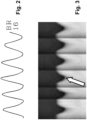
- FIGURE 3 illustrates the motion curve 44 of an anatomical feature, namely the liver dome in the illustrative example of FIGURE 3 , due to breathing measured by a 1D pencil beam navigator sequence over the same respiratory cycles that produced the breathing signal of FIGURE 2 .
- FIGURE 3 the arrow shows the motion state at the desired start of imaging data acquisition.
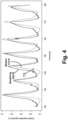
- FIGURE 4 illustrates display of both signals 16, 44 plotted against a common time axis.
- the mean or median time shift TS between these two curves 16, 44 is indicated by a time shift determined by maximizing the cross-correlation between these two curves.
- this time shift can also be thought of as a phase shift between the motion signal 44 of the anatomical feature and the concurrent physiological signal 16.
Landscapes
- Health & Medical Sciences (AREA)
- Life Sciences & Earth Sciences (AREA)
- Engineering & Computer Science (AREA)
- Physics & Mathematics (AREA)
- Biophysics (AREA)
- Physiology (AREA)
- General Health & Medical Sciences (AREA)
- Signal Processing (AREA)
- Surgery (AREA)
- Molecular Biology (AREA)
- Medical Informatics (AREA)
- Public Health (AREA)
- Veterinary Medicine (AREA)
- Heart & Thoracic Surgery (AREA)
- Animal Behavior & Ethology (AREA)
- Biomedical Technology (AREA)
- Pathology (AREA)
- Nuclear Medicine, Radiotherapy & Molecular Imaging (AREA)
- Computer Vision & Pattern Recognition (AREA)
- Psychiatry (AREA)
- Artificial Intelligence (AREA)
- High Energy & Nuclear Physics (AREA)
- Radiology & Medical Imaging (AREA)
- Pulmonology (AREA)
- General Physics & Mathematics (AREA)
- Condensed Matter Physics & Semiconductors (AREA)
- Power Engineering (AREA)
- Cardiology (AREA)
- Magnetic Resonance Imaging Apparatus (AREA)
Description
- The following relates generally to the medical imaging arts, gated medical imaging arts, magnetic resonance imaging arts, and related arts.
- Where imaging artefacts due to respiration or cardiac pulsation in magnetic resonance (MR) imaging scans are of concern, a physiology sensor may be used during MR examinations to measure the relevant physiology signal and compute a physiology curve. This signal can be used during imaging to trigger the data acquisition or for gating. The physiological sensor may, for example, measure respiratory motion using an air-filled belt attached to a pressure sensor, or an optical camera can track the motion of a body part or of a dedicated marker and the respiratory signal derived from the imaged motion. Cardiac pulsation is often measured using a pulse pickup photoplethysmography (PPG) sensor or an electrocardiogram (ECG) device. Alternatively, optical camera systems measuring the variation of reflected light over a skin area can be used to monitor cardiac activity. The respiration or cardiac signal measured by such a physiological sensor is a surrogate for the motion of the internal organs being imaged by the MR imaging.
- United States patent application publication
US 2015/0157277 A1 discloses a control unit of an MRI apparatus configured to respond to positional changes of body motion, such as respiratory motion, in various directions and to prevent an increase in the imaging time due to acquisition of body motion information or the occurrence of dead time in the measurement. The control unit of an MRI apparatus acquires association information in which body motion information detected by an external monitor, such as a pressure sensor for monitoring the movement of an object to be examined, and body motion information measured from an NMR signal by the navigator sequence are associated with each other in advance. During imaging, body motion information from the navigator is estimated using body motion information detected by an external monitor mounted on the object to be examined and the association information acquired in advance, and control, such as performing gating imaging or correcting the imaging slice position based on the estimated body motion position, is performed. - United States patent application publication
US 2006/0183999 A1 discloses a method and system for imaging by predicting, from multiple real time MR imaging data, motion of an object and subsequently obtaining high-resolution imaging data of the object using the predicted motion of the object. Thus, the process uses real time images to derive a history of the motion of the object and thereby generate a predicted trajectory of the object and then uses this trajectory to determine the projected position of the object during a subsequent, separate, high-resolution data acquisition phase. - United States patent application publication
WO 2015/024110 A1 discloses an MRI imaging sequence, the Septal Scout. This technique can determine the timing of diastasis windows for the purpose of cardiac gating in applications such as high-resolution coronary MRA. The Septal Scout acquires 1D MR images along the long-axis of the basal ventricular septum either through projection imaging or 2D excitations. Each acquisition produces a line of data along the ventricular septum. The acquisition is repeated over time to generate a time-map of Septal Scouts. The data from the Septal Scout time-map is processed to generate a velocity graph of an ROI near the basal septum. From this graph, the beginning and end of diastasis is determined. This timing information is available for use to facilitate cardiac gating in subsequent high-resolution MR angiography. - The following discloses new and improved systems and methods.
- A device in accordance with the invention is defined in claim 1. A storage medium in accordance with the invention is defined in claim 6. A method in accordance with the invention is defined in claim 11.
- One advantage resides in providing physiological gating with improved fidelity to a desired state of the internal organ(s) being imaged.
- Another advantage resides in providing gated MR imaging more accurately targeting a desired state of the internal organ(s) being imaged.
- Another advantage resides in providing gated MR imaging with user selection of the desired state of the internal organ(s) isolated by the gating.
- A given embodiment may provide none, one, two, more, or all of the foregoing advantages, and/or may provide other advantages as will become apparent to one of ordinary skill in the art upon reading and understanding the present disclosure.
- The drawings are only for purposes of illustrating the preferred embodiments and are not to be construed as limiting the invention.
-
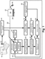
FIGURE 1 diagrammatically illustrates a magnetic resonance (MR) imaging device including respiratory gating as disclosed herein. -
FIGURE 2 diagrammatically illustrates a respiratory monitor waveform as a function of time. -
FIGURE 3 diagrammatically illustrates a navigator feature waveform as a function of time. -
FIGURE 4 diagrammatically illustrates respiratory monitor and navigator feature waveforms plotted together, with certain salient measurements indicated. - An implicit assumption made during typical gated MR imaging is that the physiological signal (e.g. respiration or cardiac cycling signal) measured by a physiological sensor is closely correlated with, and "in phase with", the dominant motion of the internal organs and that motion state of the internal organ, such as end-expiration or end-inspiration (or end-diastole and end-systole). In some gating devices, a pre-set or operator-set constant time delay can be added to the physiological signal gating event detected within each respiratory or cardiac cycle measured by the physiological device. It is recognized herein that these assumptions may be in error for a particular patient or a particular MR imaging examination. In gating approaches disclosed herein, for optimal image quality the gating time offset is set individually for each patient and each MR imaging examination.
- With reference to
FIGURE 1 , a gated magnetic resonance (MR) imaging system includes anMR imaging device 10, which may by way of non-limiting illustration comprise an Ingenia™ MR imaging device available from Koninklijke Philips N.V., Eindhoven, the Netherlands. A physiological monitor 12 is provided to monitor a physiological signal which is used for the gating. In the illustrative embodiments, the physiological monitor 12 is a respiratory monitor in the form of an air-filled belt attached to a pressure sensor, such that as the patient inhales the pressure in the air-filled belt increases and as the patient exhales the pressure decreases, so that the pressure as a function of time is a representation of the patient respiration as a function of time. (While the term "patient" is used herein for brevity, it will be understood that the MR imaging subject may be a hospital patient, an out-patient, a human subject receiving a medical screening, an athlete or other person receiving a medical clearance including an MR imaging examination, or so forth). The illustrative belt-based respiratory monitor 12 is merely an example, and it will be understood that the respiratory monitor may be chosen to monitor another chosen physiological variable used for the gating. As another example, the physiological monitor may be an electrocardiographic (ECG) device monitoring cardiac cycling - such a physiological monitor is suitable for cardiac gating. The physiological monitor 12 includes or is connected with aphysiological monitor controller 14, e.g. an electronic processor connected to read the pressure sensor and output an analog or digital pressure reading in the illustrative belt-based respiratory monitor 12, or an ECG controller in the case of an ECG-based cardiac monitor. The output of thephysiological monitor 12, 14 is a physiological signal (e.g. respiration signal) 16 as a function of time. - An
electronic processor 20 is programmed to perform various functions as disclosed herein. The illustrativeelectronic processor 20 is embodied as acomputer 22 having adisplay 24 and at least one user input device (e.g.illustrative keyboard 26 andmouse 28, and/or a touch-sensitive overlay of thedisplay 24 or so forth). More particularly, a non-transitory storage medium (not shown) is provided which stores instructions readable and executable by theelectronic processor 20 to perform the disclosed various functions. The non-transitory storage medium may, by way of non-limiting example, include a hard disk drive or other magnetic storage medium; an optical disk or other optical storage medium; a solid state drive (SSD) or other electronic storage medium; various combinations thereof; or so forth. Theelectronic processor 20 implements anMR controller 30 that controls theMR imaging device 10 to perform MR imaging data acquisition, and implements MR image reconstruction anddisplay processing 32, e.g. performing a Fourier reconstruction or other MR image reconstruction to convert acquired k-space MR imaging data to an image in image space and operating thedisplay 24 to display the reconstructed image. - With continuing reference to
FIGURE 1 , a gatedMR imaging sequence 36 is stored on a non-transitory storage medium (e.g. the same non-transitory storage medium storing instructions read and executed by the electronic processor 20). Additionally, anavigator pulse sequence 40 is stored on the non-transitory storage medium. TheMR controller 30 is programmed to operate theMR imaging device 10 to perform the gatedMR imaging sequence 36 using gating times defined as occurrence times of gating events detected by thephysiological monitor 12, 14 modified by a gating time offset determined, as disclosed herein, using thenavigator pulse sequence 40. - The
navigator pulse sequence 40 is a fast MRI sequence that generated MR data (e.g. k-space samples) that can be converted to image space. Thenavigator pulse sequence 40 can be a fast two-dimensional (2D) or three-dimensional (3D) imaging sequence that acquires a 2D or 3D navigator image, respectively. Alternatively, thenavigator pulse sequence 40 can be one or more one-dimensional (1D) pencil beam navigators that acquire one or more 1D navigator data set in image space. Thenavigator pulse sequence 40 is generally designed to produce a 1D, 2D, or 3D image dataset that intersects an anatomical feature having motion corresponding to the motive physiology that is the basis of the gating. For example, in the case of respiratory-gated MR imaging, a suitable anatomical feature is a thoracic diaphragm boundary or a liver boundary, as these boundaries are expected to move with the respiratory cycle. The thoracic diagram boundary moves since contraction and consequent movement of the thoracic diaphragm provides motive force for inspiration. The liver boundary is expected to move with the respiratory cycle since the liver is close to, and moves with, the thoracic diaphragm. Other anatomical features may instead be used, e.g. a selected rib of the ribcage. In the case of cardiac-gated MR imaging (not according to the invention), a suitable anatomical feature whose movement may be monitored by a navigator includes a myocardial tissue boundary making up a cardiac muscle wall, or a major artery or vein having motion induced by blood pressure waves imparted by the beating heart. These are merely illustrative examples. - The gating device (e.g.
MR controller 30 and ancillary components) determines the gating time offset by operating theMR imaging device 10 to repeatedly execute thenavigator pulse sequence 40 to generate navigator data in image space as a function of time. Amotion signal 44 of an anatomical feature as a function of time is extracted 42 from the navigator data. For example, in the case of a feature comprising the thoracic diaphragm boundary, theoperation 42 may include identifying this boundary as a steep intensity gradient in each 2D or 3D navigator image (or each 1D navigator data set in image space, in the case of a 1D pencil beam navigator), and the position of this boundary is plotted as a function of time for the time sequence of images or 1D navigator data sets to produce themotion signal 44. Concurrently with operating theMR imaging device 10 to repeatedly execute thenavigator sequence 40, a concurrentphysiological signal 16 as a function of time is generated by thephysiological monitor 12, 14. This is straightforward since the physiological monitor 12 (e.g. air-filled belt) is designed to operate with the patient loaded into theMR imaging device 10 in order to provide the gating signal; thus, the same physiological monitoring is performed during the repeated execution of thenavigator pulse sequence 40 to generate the concurrentphysiological signal 16. A gating time offset 50 is then determined by comparing themotion signal 44 of the anatomical feature as a function of time and the concurrentphysiological signal 16 as a function of time. This gating time offset 50 is thereafter used in the gating. That is, theMR controller 30 operates theMR imaging device 10 to perform gated MR imaging (i.e. executing the gated MR imaging sequence 36) using gating times defined as occurrence times of gating events detected by thephysiological monitor 12, 14 modified by the gating time offset 50. - In the illustrative example of
FIGURE 1 , the gating time offset 50 is determined by comparing thesignals physiological signal 16 in anoperation 52. This may be done automatically, e.g. the gating event may be defined as the pressure maximum (or minimum) measured for the illustrative air-filled belt respiratory monitor and such maxima (or minima) are readily detected automatically in the pressure-versus-time waveform. Alternatively, theoperation 52 may be performed manually, e.g. the pressure-versus-time waveform may be plotted and the MR operator manually selects the event using themouse 28. Similarly, in anoperation 54 an occurrence of a desired start of MR imaging data acquisition is identified in themotion signal 44. Again, this may be done either automatically or manually. For example, themotion signal 44 may be plotted as a function of time and the user selects the desired start on the plot of themotion signal 44 of the anatomical feature. Alternatively, the desired start may be selected automatically using some criterion, such as identifying the beginning of a quiescent period in which the motion is small. In the case of respiration, this usually corresponds to an end-expiration period, and it will be expected that the diaphragm (and hence its boundary) will have little motion during this period. The gating time offset 50 is then selected as a time difference between the time of the chosen gating event and the time of the desired start of MR imaging data acquisition. - It should be noted that gating can be performed either prospectively (not according to the invention) or retrospectively. In embodiments in which the gated MR imaging employs prospective gating, the MR imaging data acquisition is triggered at the gating times defined as occurrence times of gating events detected by the physiological monitor modified by the gating time offset 50. In this case, the gating time offset 50 should be a gating delay, i.e. the modification is to delay the start of MR imaging data acquisition by the gating time offset.
- In the case of retrospective gating, MR imaging data are acquired continuously while recording the gating events detected using the
physiological monitor 12, 14, and the collected imaging data are retrospectively gated using the recorded gating events modified by the gating time offset 50. The events are marked with the event times + offset as start point of acceptance windows to validate or invalidate respective data and track the data measured until completion. - In a variant embodiment, the gating time offset 50 is determined automatically in an
operation 56 by computing a time shift between the twosignals physiological signal 16 and themotion signal 44 are expected to be at least quasiperiodic (in the case of respiratory or cardiac gating) so that a phase shift can be defined between the twosignals - The foregoing are merely illustrative examples of some approaches for determining the gating time offset 50 by comparing the
motion signal 44 of the anatomical feature as a function of time and the concurrentphysiological signal 16 as a function of time. Moreover, the disclosed approaches are not mutually exclusive. For example, the approach of identifying 52 a trigger event in thephysiological signal 16 and identifying 54 a desired start time in themotion signal 44 and taking the difference as the gating time offset 50 can be augmented by computing the time difference bycorrelation 56 in order to ensure the times identified in theoperations motion signal 44 of the anatomical feature as a function of time is leveraged to account for patient-specific or even imaging scan-specific variations in the time offset between the measured physiological signal (e.g. respiratory signal or cardiac signal) and the motion of the imaged anatomy produced by the physiological process (e.g. respiration or cardiac cycling). - In the illustrative examples herein, while a single
electronic processor 20 is illustrated for brevity, it will be understood that the electronic processing disclosed herein may alternatively be embodied by a plurality of operatively interconnected electronic processors. For example, theMR controller 30 may be implemented as a dedicated electronic controller while the reconstruction/display 32 may be implemented by a different computer. It is also contemplated for the physiological monitor controller to be integrated with the electronic processor that controls theMR imaging device 10 and/or with the electronic processor that reconstructs and displays the MR images. Likewise, wherever herein the term "non-transitory storage medium" or the like is employed, it is to be understood that the storage medium may be a single storage medium or may include a plurality of storage media. For example, it is contemplated to store the instructions executed by theMR controller 30 on a different storage medium from the storage medium that stores the imaging andnavigator sequences - With reference now to
FIGURES 2-4 , a more specific illustrative example is presented, relating to respiratory-gated MR imaging. In this example, at the beginning of the imaging exam, the navigator (1D, 2D or 3D) signal is acquired using theMR imaging device 10 repeatedly executing thenavigator pulse sequence 40. The navigator is positioned (either manually, e.g. using scout scans, or automatically) at the location of the target moving structure (i.e., the anatomical feature whose motion is tracked). Real-time navigator images of the moving anatomical feature over a few respiratory or cardiac cycles (or other physiological cycle used for the gating) are acquired. Themotion curve 44 representative of the main motion direction is computed 42 from the navigator images using image analysis techniques, e.g. edge detection, region segmentation, or so forth. Simultaneously, thephysiology signal 16 measured by thephysiology sensor 12, 14 is acquired. In this example, the gating time offset 50 is determined as follows. The mean (or median) shift between the twosignals operations 52, 54), either manually by the operator or automatically based on some pre-settings. This may be done, for example, manually using a graphical user interface. The gating time offset 50 is computed based on the mean shift and the position of the desired motion state within one respiration cycle (for the illustrative example of respiratory gating).FIGURE 2 illustrates a suitable example of thephysiological signal 16, here embodied as a breathing signal determined from analyzing movement of a shadow of the chest on a wall of a magnet bore of theMR imaging device 10. (By contrast, in the embodiment ofFIGURE 1 , this breathing signal is provided by the air-filled belt 12).FIGURE 3 illustrates themotion curve 44 of an anatomical feature, namely the liver dome in the illustrative example ofFIGURE 3 , due to breathing measured by a 1D pencil beam navigator sequence over the same respiratory cycles that produced the breathing signal ofFIGURE 2 . InFIGURE 3 , the arrow shows the motion state at the desired start of imaging data acquisition.FIGURE 4 illustrates display of bothsignals FIGURE 4 , the mean or median time shift TS between these twocurves signals motion signal 44 of the anatomical feature and the concurrentphysiological signal 16. - The invention has been described with reference to the preferred embodiments. Modifications and alterations may occur to others upon reading and understanding the preceding detailed description. It is intended that the invention be construed as including all such modifications and alterations insofar as they come within the scope of the appended claims.
Claims (13)
- A gating device for a magnetic resonance (MR) imaging device, the gating device comprising:a physiological monitor (12, 14);an electronic processor (20); anda non-transitory storage medium storing a navigator pulse sequence (40), a gated MR imaging sequence (36), and instructions readable and executable by the electronic processor to perform a gated MR imaging method including:operating the MR imaging device to repeatedly execute the navigator pulse sequence to generate navigator data in image space as a function of time;extracting a motion signal (44) of an anatomical feature as a function of time from the navigator data;concurrently with operating the MR imaging device to repeatedly execute the navigator sequence, acquiring a concurrent physiological signal (16) as a function of time generated by the physiological monitor;determining a gating time offset (50) by comparing the motion signal of the anatomical feature as a function of time and the concurrent physiological signal as a function of time by computing (56) a time corresponding to a phase shift between the motion signal (44) of the anatomical feature and the concurrent physiological signal (16); andoperating the MR imaging device to perform the gated MR imaging sequence using gating times defined as occurrence times of gating events detected by the physiological monitor modified by the gating time offset;wherein the gated MR imaging employs retrospective gating in which MR imaging data are acquired continuously while recording the gating events detected using the physiological monitor (12, 14) and retrospectively gated using the recorded gating events modified by the gating time offset (50), wherein the physiological monitor (12, 14) comprises a respiratory monitor and the gated MR imaging is respiratory-gated MR imaging.
- The gating device of any one of claim 1 further comprising:a display (24); anda user input device (26, 28);wherein the gated MR imaging method further includes:operating the display to plot the motion signal (44) of the anatomical feature and the concurrent physiological signal (16) against a common time axis;via the user input device, receiving (52) a user input indicating a gating event on the plot of the concurrent physiological signal;via the user input device, receiving (54) a user input indicating a desired start of MR imaging data acquisition on the plot of the motion signal of the anatomical feature; andcomputing the gate time offset (50) based on a time difference between the indicated gating event and the indicated desired start of MR imaging data acquisition.
- The gating device of claim 1 wherein the extracting comprises:
extracting a motion signal (44) of a thoracic diaphragm boundary as a function of time from the navigator data. - The gating device of any one of claims 1-3 wherein the navigator pulse sequence (40) is a pencil beam navigator and operating the MR imaging device (10) to repeatedly execute the pencil beam navigator pulse sequence generates a time sequence of one-dimensional (1D) navigator data sets in image space.
- The gating device of any one of claims 1-4 wherein the navigator pulse sequence (40) is a two- or three-dimensional (2D or 3D) navigator pulse sequence and operating the MR imaging device (10) to repeatedly execute the 2D or 3D navigator pulse sequence generates a time sequence of 2D or 3D images.
- A non-transitory storage medium storing:a navigator pulse sequence (40);a gated magnetic resonance (MR) imaging sequence (36); andinstructions readable and executable by an electronic processor (20) to perform a gated MR imaging method comprising:operating an MR imaging device (10) to repeatedly execute the navigator pulse sequence to generate navigator data in image space as a function of time;extracting a motion signal (44) of an anatomical feature as a function of time from the navigator data;concurrently with operating the MR imaging device to repeatedly execute the navigator sequence, acquiring a concurrent respiratory cycling signal (16) as a function of time generated by a respiratory monitor (12, 14);determining a gating time offset (50) by comparing the motion signal of the anatomical feature as a function of time and the concurrent respiratory or cardiac cycling signal as a function of time by computing (56) a time corresponding to a phase shift between the motion signal (44) of the anatomical feature and the concurrent respiratory signal (16); andoperating the MR imaging device to perform the gated MR imaging sequence using gating times defined as occurrence times of gating events detected by the respiratory monitor modified by the gating time offset,wherein the gated MR imaging employs retrospective gating in which MR imaging data is acquired continuously while recording the gating events detected using the respiratory monitor (12, 14) and retrospectively gated using the recorded gating events modified by the gating time offset (50).
- The non-transitory storage medium of claim 6 wherein the gated MR imaging method further includes:
operating a display (24) to plot the motion signal (44) of the anatomical feature and the concurrent respiratory or cardiac signal (16) against a common time axis. - The non-transitory storage medium of any one of claims 6-7 wherein the gated MR imaging method further includes:receiving identification of, or automatically identifying, a gating event (52) in the concurrent respiratory or cardiac signal;receiving identification of, or automatically identifying, a desired start (54) of MR imaging data acquisition in the motion signal of the anatomical feature; andcomputing the gate time offset (50) based on a time difference between the indicated gating event and the indicated desired start of MR imaging data acquisition.
- The non-transitory storage medium of any one of claims 6-8 wherein the extracting comprises:
extracting a motion signal (44) of an organ boundary as a function of time from the navigator data. - The non-transitory storage medium of any one of claims 6-9 wherein one of:the navigator pulse sequence (40) is a pencil beam navigator and operating the MR imaging device (10) to repeatedly execute the pencil beam navigator pulse sequence generates a time sequence of one-dimensional (1D) navigator data sets in image space;the navigator pulse sequence is a two-dimensional (2D) navigator pulse sequence and operating the MR imaging device to repeatedly execute the 2D navigator pulse sequence generates a time sequence of 2D images; orthe navigator pulse sequence is a three-dimensional (3D) navigator pulse sequence and operating the MR imaging device to repeatedly execute the 3D navigator pulse sequence generates a time sequence of 3D images.
- A gated magnetic resonance (MR) imaging method comprising:repeatedly executing a navigator pulse sequence (40) using an MR imaging device (10) to generate navigator data in image space as a function of time;extracting a motion signal (44) of an anatomical feature as a function of time from the navigator data;concurrently with operating the MR imaging device to repeatedly execute the navigator sequence, acquiring a concurrent respiratory cycling signal (16) as a function of time generated by a respiratory monitor (12, 14);determining a gating time offset (50) by comparing the motion signal of the anatomical feature as a function of time and the concurrent respiratory cycling signal as a function of time by computing (56) a time corresponding to a phase shift between the motion signal (44) of the anatomical feature and the concurrent respiratory cycling signal (16); andoperating the MR imaging device to perform a gated MR imaging sequence (36) using gating times defined as occurrence times of gating events detected by the respiratory monitor modified by the gating time offset;wherein the gated MR imaging employs retrospective gating in which MR imaging data acquisition is acquired continuously while recording the gating events detected using the respiratory or cardiac monitor (12, 14) and retrospectively gated using the recorded gating events modified by the gating time offset (50).
- The gated MR imaging method of claim 11 wherein the anatomical feature is an organ boundary.
- The gated MR imaging method of any one of claims 11-12 wherein determining the gating time offset (50) includes:
computing the gate time offset as a time difference between a gating event in the respiratory cycling signal (16) and a reference point in the motion signal (44) of the anatomical feature.
Applications Claiming Priority (2)
| Application Number | Priority Date | Filing Date | Title |
|---|---|---|---|
| US201662433835P | 2016-12-14 | 2016-12-14 | |
| PCT/EP2017/082237 WO2018108821A1 (en) | 2016-12-14 | 2017-12-11 | Automated computation of trigger delay for triggered magnetic resonance imaging sequences |
Publications (2)
| Publication Number | Publication Date |
|---|---|
| EP3554341A1 EP3554341A1 (en) | 2019-10-23 |
| EP3554341B1 true EP3554341B1 (en) | 2023-08-30 |
Family
ID=60923451
Family Applications (1)
| Application Number | Title | Priority Date | Filing Date |
|---|---|---|---|
| EP17825151.8A Active EP3554341B1 (en) | 2016-12-14 | 2017-12-11 | Retrospective gating of mri |
Country Status (5)
| Country | Link |
|---|---|
| US (1) | US11344262B2 (en) |
| EP (1) | EP3554341B1 (en) |
| JP (2) | JP2020501683A (en) |
| CN (1) | CN110177491B (en) |
| WO (1) | WO2018108821A1 (en) |
Families Citing this family (2)
| Publication number | Priority date | Publication date | Assignee | Title |
|---|---|---|---|---|
| CN109480881A (en) * | 2018-12-29 | 2019-03-19 | 上海联影医疗科技有限公司 | PET-MR Syncgated method, apparatus, PET-MR detection device and storage medium |
| TWI832696B (en) * | 2023-02-09 | 2024-02-11 | 陳右穎 | Image reassembled system, method and computer-readable storage medium applied to magnetic resonance imaging |
Family Cites Families (17)
| Publication number | Priority date | Publication date | Assignee | Title |
|---|---|---|---|---|
| US6321107B1 (en) * | 1999-05-14 | 2001-11-20 | General Electric Company | Determining linear phase shift in conjugate domain for MR imaging |
| US7367953B2 (en) | 2003-11-26 | 2008-05-06 | Ge Medical Systems Global Technology Company | Method and system for determining a period of interest using multiple inputs |
| US7756565B2 (en) * | 2003-11-26 | 2010-07-13 | General Electric Company | Method and system for composite gating using multiple inputs |
| US8352013B2 (en) * | 2005-01-18 | 2013-01-08 | Siemens Medical Solutions Usa, Inc. | Method and system for motion compensation in magnetic resonance (MR) imaging |
| CA2705757A1 (en) * | 2007-11-19 | 2009-05-28 | Pyronia Medical Technologies, Inc. | Patient positioning system and methods for diagnostic radiology and radiotherapy |
| JP5542495B2 (en) | 2009-06-08 | 2014-07-09 | 株式会社東芝 | Magnetic resonance imaging system |
| US8600475B2 (en) * | 2011-04-05 | 2013-12-03 | University Of Massachusetts | Relaxation-corrected ECG-triggering and navigator-gating technique |
| US8971602B2 (en) * | 2011-04-22 | 2015-03-03 | Mayo Foundation For Medical Education And Research | Method for magnetic resonance elastography using transient waveforms |
| US8768034B2 (en) * | 2012-03-20 | 2014-07-01 | Siemens Medical Solutions Usa, Inc. | Motion compensated MR imaging system |
| US20150157277A1 (en) * | 2012-08-13 | 2015-06-11 | Hitachi Medical Corporation | Magnetic resonance imaging apparatus and magnetic resonance imaging method |
| DE102012216248A1 (en) | 2012-09-13 | 2014-03-13 | Siemens Aktiengesellschaft | A medical imaging device comprising a sensor unit for detecting a physiological signal and a method for detecting a cardiac cycle of a patient |
| US9207300B2 (en) * | 2012-10-26 | 2015-12-08 | Siemens Medical Solutions Usa, Inc. | Automatic system for timing in imaging |
| JP6109598B2 (en) * | 2013-02-26 | 2017-04-05 | 東芝メディカルシステムズ株式会社 | Magnetic resonance imaging system |
| DE102013205402A1 (en) | 2013-03-27 | 2014-10-02 | Siemens Aktiengesellschaft | Method for adjusting at least one magnetic resonance image data set of a mobile examination subject and a correspondingly configured magnetic resonance apparatus |
| EP3036553A4 (en) * | 2013-08-19 | 2017-04-19 | Sunnybrook Research Institute | Method for determining diastasis timing using an mri septal scout |
| JP6483691B2 (en) * | 2013-12-02 | 2019-03-13 | コーニンクレッカ フィリップス エヌ ヴェKoninklijke Philips N.V. | Magnetic resonance imaging system and method |
| US11801114B2 (en) * | 2017-09-11 | 2023-10-31 | Philipp K. Lang | Augmented reality display for vascular and other interventions, compensation for cardiac and respiratory motion |
-
2017
- 2017-12-11 WO PCT/EP2017/082237 patent/WO2018108821A1/en unknown
- 2017-12-11 JP JP2019531632A patent/JP2020501683A/en active Pending
- 2017-12-11 EP EP17825151.8A patent/EP3554341B1/en active Active
- 2017-12-11 US US16/468,734 patent/US11344262B2/en active Active
- 2017-12-11 CN CN201780083282.8A patent/CN110177491B/en active Active
-
2023
- 2023-06-21 JP JP2023101641A patent/JP2023126817A/en active Pending
Also Published As
| Publication number | Publication date |
|---|---|
| US11344262B2 (en) | 2022-05-31 |
| US20200093443A1 (en) | 2020-03-26 |
| WO2018108821A1 (en) | 2018-06-21 |
| CN110177491A (en) | 2019-08-27 |
| CN110177491B (en) | 2022-07-12 |
| EP3554341A1 (en) | 2019-10-23 |
| JP2020501683A (en) | 2020-01-23 |
| JP2023126817A (en) | 2023-09-12 |
Similar Documents
| Publication | Publication Date | Title |
|---|---|---|
| Maffei et al. | Left and right ventricle assessment with Cardiac CT: validation study vs. Cardiac MR | |
| JP6596020B2 (en) | Magnetic resonance imaging with motion correction using pre-pulse and navigator | |
| JP5581511B2 (en) | Computer-readable storage medium having recorded thereon a computer program for plotting a center point locus | |
| JP5944645B2 (en) | Magnetic resonance imaging system | |
| KR101713859B1 (en) | Apparatus for processing magnetic resonance image and method for processing magnetic resonance image thereof | |
| US20130253319A1 (en) | Method and system for acquiring and analyzing multiple image data loops | |
| JP2006198407A (en) | Method and system for compensation of motion in magnetic resonance (mr) imaging | |
| US8487933B2 (en) | System and method for multi-segment center point trajectory mapping | |
| JP6467341B2 (en) | Magnetic resonance imaging apparatus, image processing apparatus, diagnostic imaging apparatus, image analysis apparatus, MRI image creation method and program | |
| US11269036B2 (en) | System and method for phase unwrapping for automatic cine DENSE strain analysis using phase predictions and region growing | |
| CN106539584A (en) | MR imaging method and system | |
| US9161724B2 (en) | Multi-cardiac sound gated imaging and post-processing of imaging data based on cardiac sound | |
| JP2023126817A (en) | Automated calculation of trigger delay in trigger type magnetic resonance imaging sequence | |
| WO2015024110A1 (en) | Method for determining diastasis timing using an mri septal scout | |
| US10548494B2 (en) | Method for determining a personalized cardiac model using a magnetic resonance imaging sequence | |
| US11154213B2 (en) | Detection of position and frequency of a periodically moving organ in an MRI examination | |
| CN117202842A (en) | Method for determining heart wall movement | |
| JP4972477B2 (en) | Medical image processing device | |
| JP6510193B2 (en) | Magnetic resonance imaging apparatus and image processing apparatus | |
| JP2010246777A (en) | Medical image processing device, method, and program | |
| Schoebinger et al. | Quantification of tumor mobility during the breathing cycle using 3D dynamic MRI |
Legal Events
| Date | Code | Title | Description |
|---|---|---|---|
| STAA | Information on the status of an ep patent application or granted ep patent |
Free format text: STATUS: UNKNOWN |
|
| STAA | Information on the status of an ep patent application or granted ep patent |
Free format text: STATUS: THE INTERNATIONAL PUBLICATION HAS BEEN MADE |
|
| PUAI | Public reference made under article 153(3) epc to a published international application that has entered the european phase |
Free format text: ORIGINAL CODE: 0009012 |
|
| STAA | Information on the status of an ep patent application or granted ep patent |
Free format text: STATUS: REQUEST FOR EXAMINATION WAS MADE |
|
| 17P | Request for examination filed |
Effective date: 20190715 |
|
| AK | Designated contracting states |
Kind code of ref document: A1 Designated state(s): AL AT BE BG CH CY CZ DE DK EE ES FI FR GB GR HR HU IE IS IT LI LT LU LV MC MK MT NL NO PL PT RO RS SE SI SK SM TR |
|
| AX | Request for extension of the european patent |
Extension state: BA ME |
|
| RAP1 | Party data changed (applicant data changed or rights of an application transferred) |
Owner name: KONINKLIJKE PHILIPS N.V. |
|
| DAV | Request for validation of the european patent (deleted) | ||
| DAX | Request for extension of the european patent (deleted) | ||
| GRAP | Despatch of communication of intention to grant a patent |
Free format text: ORIGINAL CODE: EPIDOSNIGR1 |
|
| STAA | Information on the status of an ep patent application or granted ep patent |
Free format text: STATUS: GRANT OF PATENT IS INTENDED |
|
| INTG | Intention to grant announced |
Effective date: 20230405 |
|
| GRAS | Grant fee paid |
Free format text: ORIGINAL CODE: EPIDOSNIGR3 |
|
| GRAA | (expected) grant |
Free format text: ORIGINAL CODE: 0009210 |
|
| STAA | Information on the status of an ep patent application or granted ep patent |
Free format text: STATUS: THE PATENT HAS BEEN GRANTED |
|
| AK | Designated contracting states |
Kind code of ref document: B1 Designated state(s): AL AT BE BG CH CY CZ DE DK EE ES FI FR GB GR HR HU IE IS IT LI LT LU LV MC MK MT NL NO PL PT RO RS SE SI SK SM TR |
|
| REG | Reference to a national code |
Ref country code: GB Ref legal event code: FG4D |
|
| REG | Reference to a national code |
Ref country code: CH Ref legal event code: EP |
|
| REG | Reference to a national code |
Ref country code: DE Ref legal event code: R096 Ref document number: 602017073509 Country of ref document: DE |
|
| REG | Reference to a national code |
Ref country code: DE Ref legal event code: R084 Ref document number: 602017073509 Country of ref document: DE |
|
| REG | Reference to a national code |
Ref country code: IE Ref legal event code: FG4D |
|
| REG | Reference to a national code |
Ref country code: GB Ref legal event code: 746 Effective date: 20231002 |
|
| REG | Reference to a national code |
Ref country code: LT Ref legal event code: MG9D |
|
| REG | Reference to a national code |
Ref country code: NL Ref legal event code: MP Effective date: 20230830 |
|
| REG | Reference to a national code |
Ref country code: AT Ref legal event code: MK05 Ref document number: 1604306 Country of ref document: AT Kind code of ref document: T Effective date: 20230830 |
|
| PG25 | Lapsed in a contracting state [announced via postgrant information from national office to epo] |
Ref country code: GR Free format text: LAPSE BECAUSE OF FAILURE TO SUBMIT A TRANSLATION OF THE DESCRIPTION OR TO PAY THE FEE WITHIN THE PRESCRIBED TIME-LIMIT Effective date: 20231201 |
|
| PGFP | Annual fee paid to national office [announced via postgrant information from national office to epo] |
Ref country code: GB Payment date: 20231219 Year of fee payment: 7 |
|
| PG25 | Lapsed in a contracting state [announced via postgrant information from national office to epo] |
Ref country code: IS Free format text: LAPSE BECAUSE OF FAILURE TO SUBMIT A TRANSLATION OF THE DESCRIPTION OR TO PAY THE FEE WITHIN THE PRESCRIBED TIME-LIMIT Effective date: 20231230 |
|
| PG25 | Lapsed in a contracting state [announced via postgrant information from national office to epo] |
Ref country code: SE Free format text: LAPSE BECAUSE OF FAILURE TO SUBMIT A TRANSLATION OF THE DESCRIPTION OR TO PAY THE FEE WITHIN THE PRESCRIBED TIME-LIMIT Effective date: 20230830 Ref country code: RS Free format text: LAPSE BECAUSE OF FAILURE TO SUBMIT A TRANSLATION OF THE DESCRIPTION OR TO PAY THE FEE WITHIN THE PRESCRIBED TIME-LIMIT Effective date: 20230830 Ref country code: NO Free format text: LAPSE BECAUSE OF FAILURE TO SUBMIT A TRANSLATION OF THE DESCRIPTION OR TO PAY THE FEE WITHIN THE PRESCRIBED TIME-LIMIT Effective date: 20231130 Ref country code: LV Free format text: LAPSE BECAUSE OF FAILURE TO SUBMIT A TRANSLATION OF THE DESCRIPTION OR TO PAY THE FEE WITHIN THE PRESCRIBED TIME-LIMIT Effective date: 20230830 Ref country code: LT Free format text: LAPSE BECAUSE OF FAILURE TO SUBMIT A TRANSLATION OF THE DESCRIPTION OR TO PAY THE FEE WITHIN THE PRESCRIBED TIME-LIMIT Effective date: 20230830 Ref country code: IS Free format text: LAPSE BECAUSE OF FAILURE TO SUBMIT A TRANSLATION OF THE DESCRIPTION OR TO PAY THE FEE WITHIN THE PRESCRIBED TIME-LIMIT Effective date: 20231230 Ref country code: HR Free format text: LAPSE BECAUSE OF FAILURE TO SUBMIT A TRANSLATION OF THE DESCRIPTION OR TO PAY THE FEE WITHIN THE PRESCRIBED TIME-LIMIT Effective date: 20230830 Ref country code: GR Free format text: LAPSE BECAUSE OF FAILURE TO SUBMIT A TRANSLATION OF THE DESCRIPTION OR TO PAY THE FEE WITHIN THE PRESCRIBED TIME-LIMIT Effective date: 20231201 Ref country code: FI Free format text: LAPSE BECAUSE OF FAILURE TO SUBMIT A TRANSLATION OF THE DESCRIPTION OR TO PAY THE FEE WITHIN THE PRESCRIBED TIME-LIMIT Effective date: 20230830 Ref country code: AT Free format text: LAPSE BECAUSE OF FAILURE TO SUBMIT A TRANSLATION OF THE DESCRIPTION OR TO PAY THE FEE WITHIN THE PRESCRIBED TIME-LIMIT Effective date: 20230830 |
|
| PG25 | Lapsed in a contracting state [announced via postgrant information from national office to epo] |
Ref country code: PL Free format text: LAPSE BECAUSE OF FAILURE TO SUBMIT A TRANSLATION OF THE DESCRIPTION OR TO PAY THE FEE WITHIN THE PRESCRIBED TIME-LIMIT Effective date: 20230830 Ref country code: NL Free format text: LAPSE BECAUSE OF FAILURE TO SUBMIT A TRANSLATION OF THE DESCRIPTION OR TO PAY THE FEE WITHIN THE PRESCRIBED TIME-LIMIT Effective date: 20230830 |
|
| PG25 | Lapsed in a contracting state [announced via postgrant information from national office to epo] |
Ref country code: ES Free format text: LAPSE BECAUSE OF FAILURE TO SUBMIT A TRANSLATION OF THE DESCRIPTION OR TO PAY THE FEE WITHIN THE PRESCRIBED TIME-LIMIT Effective date: 20230830 |
|
| PG25 | Lapsed in a contracting state [announced via postgrant information from national office to epo] |
Ref country code: SM Free format text: LAPSE BECAUSE OF FAILURE TO SUBMIT A TRANSLATION OF THE DESCRIPTION OR TO PAY THE FEE WITHIN THE PRESCRIBED TIME-LIMIT Effective date: 20230830 Ref country code: RO Free format text: LAPSE BECAUSE OF FAILURE TO SUBMIT A TRANSLATION OF THE DESCRIPTION OR TO PAY THE FEE WITHIN THE PRESCRIBED TIME-LIMIT Effective date: 20230830 Ref country code: ES Free format text: LAPSE BECAUSE OF FAILURE TO SUBMIT A TRANSLATION OF THE DESCRIPTION OR TO PAY THE FEE WITHIN THE PRESCRIBED TIME-LIMIT Effective date: 20230830 Ref country code: EE Free format text: LAPSE BECAUSE OF FAILURE TO SUBMIT A TRANSLATION OF THE DESCRIPTION OR TO PAY THE FEE WITHIN THE PRESCRIBED TIME-LIMIT Effective date: 20230830 Ref country code: DK Free format text: LAPSE BECAUSE OF FAILURE TO SUBMIT A TRANSLATION OF THE DESCRIPTION OR TO PAY THE FEE WITHIN THE PRESCRIBED TIME-LIMIT Effective date: 20230830 Ref country code: CZ Free format text: LAPSE BECAUSE OF FAILURE TO SUBMIT A TRANSLATION OF THE DESCRIPTION OR TO PAY THE FEE WITHIN THE PRESCRIBED TIME-LIMIT Effective date: 20230830 Ref country code: SK Free format text: LAPSE BECAUSE OF FAILURE TO SUBMIT A TRANSLATION OF THE DESCRIPTION OR TO PAY THE FEE WITHIN THE PRESCRIBED TIME-LIMIT Effective date: 20230830 Ref country code: PT Free format text: LAPSE BECAUSE OF FAILURE TO SUBMIT A TRANSLATION OF THE DESCRIPTION OR TO PAY THE FEE WITHIN THE PRESCRIBED TIME-LIMIT Effective date: 20240102 |
|
| PGFP | Annual fee paid to national office [announced via postgrant information from national office to epo] |
Ref country code: DE Payment date: 20231227 Year of fee payment: 7 |