EP3553706B1 - Anti-counterfeiting element and anti-counterfeiting product - Google Patents
Anti-counterfeiting element and anti-counterfeiting product Download PDFInfo
- Publication number
- EP3553706B1 EP3553706B1 EP17877547.4A EP17877547A EP3553706B1 EP 3553706 B1 EP3553706 B1 EP 3553706B1 EP 17877547 A EP17877547 A EP 17877547A EP 3553706 B1 EP3553706 B1 EP 3553706B1
- Authority
- EP
- European Patent Office
- Prior art keywords
- magnetic
- security element
- security
- present
- units
- Prior art date
- Legal status (The legal status is an assumption and is not a legal conclusion. Google has not performed a legal analysis and makes no representation as to the accuracy of the status listed.)
- Active
Links
- 239000000463 material Substances 0.000 claims description 20
- 230000000007 visual effect Effects 0.000 claims description 13
- 239000000696 magnetic material Substances 0.000 claims description 7
- 230000003287 optical effect Effects 0.000 claims description 2
- 238000010586 diagram Methods 0.000 description 23
- 238000004519 manufacturing process Methods 0.000 description 8
- 239000000853 adhesive Substances 0.000 description 2
- 230000001070 adhesive effect Effects 0.000 description 2
- 238000010923 batch production Methods 0.000 description 2
- 238000001514 detection method Methods 0.000 description 2
- 239000002184 metal Substances 0.000 description 2
- 238000012986 modification Methods 0.000 description 2
- 230000004048 modification Effects 0.000 description 2
- 230000007935 neutral effect Effects 0.000 description 2
- 239000004020 conductor Substances 0.000 description 1
- 230000007246 mechanism Effects 0.000 description 1
- 238000000034 method Methods 0.000 description 1
- 238000007747 plating Methods 0.000 description 1
- 229920000642 polymer Polymers 0.000 description 1
Images

Classifications
-
- B—PERFORMING OPERATIONS; TRANSPORTING
- B42—BOOKBINDING; ALBUMS; FILES; SPECIAL PRINTED MATTER
- B42D—BOOKS; BOOK COVERS; LOOSE LEAVES; PRINTED MATTER CHARACTERISED BY IDENTIFICATION OR SECURITY FEATURES; PRINTED MATTER OF SPECIAL FORMAT OR STYLE NOT OTHERWISE PROVIDED FOR; DEVICES FOR USE THEREWITH AND NOT OTHERWISE PROVIDED FOR; MOVABLE-STRIP WRITING OR READING APPARATUS
- B42D25/00—Information-bearing cards or sheet-like structures characterised by identification or security features; Manufacture thereof
- B42D25/20—Information-bearing cards or sheet-like structures characterised by identification or security features; Manufacture thereof characterised by a particular use or purpose
- B42D25/23—Identity cards
-
- B—PERFORMING OPERATIONS; TRANSPORTING
- B42—BOOKBINDING; ALBUMS; FILES; SPECIAL PRINTED MATTER
- B42D—BOOKS; BOOK COVERS; LOOSE LEAVES; PRINTED MATTER CHARACTERISED BY IDENTIFICATION OR SECURITY FEATURES; PRINTED MATTER OF SPECIAL FORMAT OR STYLE NOT OTHERWISE PROVIDED FOR; DEVICES FOR USE THEREWITH AND NOT OTHERWISE PROVIDED FOR; MOVABLE-STRIP WRITING OR READING APPARATUS
- B42D25/00—Information-bearing cards or sheet-like structures characterised by identification or security features; Manufacture thereof
- B42D25/20—Information-bearing cards or sheet-like structures characterised by identification or security features; Manufacture thereof characterised by a particular use or purpose
- B42D25/29—Securities; Bank notes
-
- B—PERFORMING OPERATIONS; TRANSPORTING
- B42—BOOKBINDING; ALBUMS; FILES; SPECIAL PRINTED MATTER
- B42D—BOOKS; BOOK COVERS; LOOSE LEAVES; PRINTED MATTER CHARACTERISED BY IDENTIFICATION OR SECURITY FEATURES; PRINTED MATTER OF SPECIAL FORMAT OR STYLE NOT OTHERWISE PROVIDED FOR; DEVICES FOR USE THEREWITH AND NOT OTHERWISE PROVIDED FOR; MOVABLE-STRIP WRITING OR READING APPARATUS
- B42D25/00—Information-bearing cards or sheet-like structures characterised by identification or security features; Manufacture thereof
- B42D25/30—Identification or security features, e.g. for preventing forgery
- B42D25/36—Identification or security features, e.g. for preventing forgery comprising special materials
- B42D25/369—Magnetised or magnetisable materials
-
- B—PERFORMING OPERATIONS; TRANSPORTING
- B42—BOOKBINDING; ALBUMS; FILES; SPECIAL PRINTED MATTER
- B42D—BOOKS; BOOK COVERS; LOOSE LEAVES; PRINTED MATTER CHARACTERISED BY IDENTIFICATION OR SECURITY FEATURES; PRINTED MATTER OF SPECIAL FORMAT OR STYLE NOT OTHERWISE PROVIDED FOR; DEVICES FOR USE THEREWITH AND NOT OTHERWISE PROVIDED FOR; MOVABLE-STRIP WRITING OR READING APPARATUS
- B42D25/00—Information-bearing cards or sheet-like structures characterised by identification or security features; Manufacture thereof
- B42D25/30—Identification or security features, e.g. for preventing forgery
- B42D25/36—Identification or security features, e.g. for preventing forgery comprising special materials
- B42D25/373—Metallic materials
-
- B—PERFORMING OPERATIONS; TRANSPORTING
- B42—BOOKBINDING; ALBUMS; FILES; SPECIAL PRINTED MATTER
- B42D—BOOKS; BOOK COVERS; LOOSE LEAVES; PRINTED MATTER CHARACTERISED BY IDENTIFICATION OR SECURITY FEATURES; PRINTED MATTER OF SPECIAL FORMAT OR STYLE NOT OTHERWISE PROVIDED FOR; DEVICES FOR USE THEREWITH AND NOT OTHERWISE PROVIDED FOR; MOVABLE-STRIP WRITING OR READING APPARATUS
- B42D25/00—Information-bearing cards or sheet-like structures characterised by identification or security features; Manufacture thereof
- B42D25/40—Manufacture
- B42D25/405—Marking
-
- G—PHYSICS
- G06—COMPUTING; CALCULATING OR COUNTING
- G06K—GRAPHICAL DATA READING; PRESENTATION OF DATA; RECORD CARRIERS; HANDLING RECORD CARRIERS
- G06K19/00—Record carriers for use with machines and with at least a part designed to carry digital markings
- G06K19/06—Record carriers for use with machines and with at least a part designed to carry digital markings characterised by the kind of the digital marking, e.g. shape, nature, code
- G06K19/06187—Record carriers for use with machines and with at least a part designed to carry digital markings characterised by the kind of the digital marking, e.g. shape, nature, code with magnetically detectable marking
-
- G—PHYSICS
- G06—COMPUTING; CALCULATING OR COUNTING
- G06K—GRAPHICAL DATA READING; PRESENTATION OF DATA; RECORD CARRIERS; HANDLING RECORD CARRIERS
- G06K7/00—Methods or arrangements for sensing record carriers, e.g. for reading patterns
- G06K7/08—Methods or arrangements for sensing record carriers, e.g. for reading patterns by means detecting the change of an electrostatic or magnetic field, e.g. by detecting change of capacitance between electrodes
- G06K7/082—Methods or arrangements for sensing record carriers, e.g. for reading patterns by means detecting the change of an electrostatic or magnetic field, e.g. by detecting change of capacitance between electrodes using inductive or magnetic sensors
- G06K7/087—Methods or arrangements for sensing record carriers, e.g. for reading patterns by means detecting the change of an electrostatic or magnetic field, e.g. by detecting change of capacitance between electrodes using inductive or magnetic sensors flux-sensitive, e.g. magnetic, detectors
-
- G—PHYSICS
- G07—CHECKING-DEVICES
- G07D—HANDLING OF COINS OR VALUABLE PAPERS, e.g. TESTING, SORTING BY DENOMINATIONS, COUNTING, DISPENSING, CHANGING OR DEPOSITING
- G07D7/00—Testing specially adapted to determine the identity or genuineness of valuable papers or for segregating those which are unacceptable, e.g. banknotes that are alien to a currency
- G07D7/004—Testing specially adapted to determine the identity or genuineness of valuable papers or for segregating those which are unacceptable, e.g. banknotes that are alien to a currency using digital security elements, e.g. information coded on a magnetic thread or strip
-
- G—PHYSICS
- G07—CHECKING-DEVICES
- G07D—HANDLING OF COINS OR VALUABLE PAPERS, e.g. TESTING, SORTING BY DENOMINATIONS, COUNTING, DISPENSING, CHANGING OR DEPOSITING
- G07D7/00—Testing specially adapted to determine the identity or genuineness of valuable papers or for segregating those which are unacceptable, e.g. banknotes that are alien to a currency
- G07D7/04—Testing magnetic properties of the materials thereof, e.g. by detection of magnetic imprint
Definitions
- the present invention relates to the technical field of anti-counterfeiting, and particularly relates to a security element and a security product.
- Most of the valuable documents contain security elements made of magnetic materials, such as magnetic icons, magnetic security threads or strips.
- the magnetic materials can be applied to the security elements continuously or in some areas of the security elements, for example, in the form of a magnetic icon or magnetic code.
- the patent application of CN102971748A has proposed a method for forming a magnetic code region by using two or more materials with different coercivity, wherein the magnetic unit formed by the two materials has a certain imperceptibility to the magnetic code and has higher anti-counterfeiting performance, but the printing overprinting of the two materials has high production difficulty, and the security element can be recognized only through special detection equipment.
- WO 2006/042667 A1 (GIESECKE & DEVRIENT GMBH [DE]; SCHUETZMANN JUERGEN [DE] ET AL.) 27 April 2006 relates to a security element comprising at least two magnetic materials that are provided with a different coercive field intensity while being applied to and/or inserted into the security element in such a way that the remanence thereof is the same.
- WO 03/002355 A1 GIESECKE & DEVRIENT GMBH [DE]; HEIM MANFRED [DE] 9 January 2003 relates to a security element that is provided with a first code consisting of a magnetic material and/or a second code consisting of an electrically conductive material, in addition to a third, optically readable code, which is in the magnetic and/or electrically conductive code or is preferably produced with a third neutral material, wherein the neutral material is neither electrically conductive nor magnetic.
- WO 2014/161674 A1 (MANTEGAZZA A ARTI GRAFICI [IT]) 12 April 1989 relates to a security element having a magnetic coding composed of magnetic elements.
- An object of the present invention is to provide a security element and a security product, wherein the security element has better imperceptibility to magnetic code and higher anti-counterfeiting performance. Printing production is simpler due to no need of high-precision overprinting, and the security element can be recognized through universal detection equipment.
- the present invention provides a security element, comprising: a base material; and one or more magnetic units located on the base material, wherein a magnetic signal width of at least a first magnetic unit of the one or more magnetic units is smaller than the visual width of the first magnetic unit.
- the one or more magnetic units are made of one magnetic material.
- the material is magnetically conductive ink.
- a magnetic content of at least a first region of the first magnetic unit is greater than a magnetic content of remaining regions of the first magnetic unit.
- the one or more magnetic units are periodically arranged on the base material.
- each of the one or more magnetic units is one or more of the following: letters, numbers, words and/or patterns.
- the magnetic regions of the one or more magnetic units have optical opacity.
- the present invention further provides a security product, which comprises the above-mentioned security element.
- the magnetic signal width generated by a magnetic sensor for at least one magnetic unit in the security element is smaller than the visual width of the magnetic unit, and the authenticity of the security element can be easily detected by this feature, thus improving the anti-counterfeiting performance of the security element and having better imperceptibility to magnetic code, meanwhile, the security element can achieve batch production easily and can be recognized by a commercially available currency detector.
- first and second referred in the embodiment of the present invention are merely used for descriptive purposes and are not to be interpreted as indicating or implying a relative importance or implicitly indicating the number of the indicated technical characteristics.
- the embodiment of the present invention provides a security element as defined in claim 1.
- a pulse signal corresponding to the magnetic unit can be obtained when the security element is detected by a magnetic sensor.
- a distance between a wave peak and a wave trough of the pulse signal corresponding to edges of a region capable of generating a pulse signal in the magnetic unit is defined as a magnetic signal width.
- the security element provided by the embodiment of the present invention at least has one magnetic unit, wherein the magnetic signal width corresponding to the magnetic unit is smaller than the visual width of the magnetic unit, so that the pulse signal will not be reproduced depending on the appearance characteristics of the security element, thereby improving the anti-counterfeiting performance of the security element.
- the anti-counterfeiting performance of the security element can be detected easily, for example, the authenticity of the security element can be recognized by a commercially available currency detector, and the security element has low production difficulty and is easy for batch production.
- the one or more magnetic units may be made of one kind of magnetic material, for example, the material can be conductive ink.
- the magnetic unit is made of one kind of material, therefore, it can be made by one-step printing, has simple manufacturing process, and greatly reduces the production difficulty and manufacturing cost of the security element.
- the magnetic signal width may be made smaller than the visual width of the magnetic unit by controlling the ink contents of different regions of the magnetic unit.
- the security element is detected by a magnetic sensor, the width of the machine-readable identifiable region is only the same as the width of the region of the portion with a larger magnetic content, therefore, the magnetic signal width may be made smaller than the visual width of the magnetic unit by setting the magnetic content of at least one region of the magnetic unit larger than that of the remaining regions.
- the magnetic unit can be one or more of the following: letters, numbers, words and/or patterns.
- the magnetic unit can be periodically or aperiodically arranged on the base material.
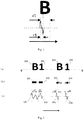
- Fig. 1 is a schematic diagram of a magnetic unit exemplified by the letter "B". As shown in Fig. 1 , the magnetic content of the left portion of the letter “B” is larger than that of the right portion, but the letter “B” is uniformly opaque as a whole under the visual effect. When machine-reading is performed on the letter “B” in the direction of the arrow, the generated magnetic signal width c1 is smaller than the visual width a1 of the letter "B". It should be understood that the letter “B” is used herein for illustration only and is not intended to limit the present invention.
- Fig. 2 (a) is schematic diagrams of magnetic units composed of letters and numbers in the prior art and an embodiment of the present invention, respectively.
- the letter 201 and the number 202 are two magnetic units made by the prior art
- the letter 203 and the number 204 are magnetic units provided by the embodiment of the present invention.
- the letters 201 and 203 have the same visual effect, and so do the numbers 202 and 204.
- Fig. 2 (b) is cross-sectional views of the magnetic units shown in Fig. 2 (a) in the direction of the broken line and the arrow.
- the cross-sectional views 211 and 212 show that the regions of the letter 201 and the number 202 produced by using the prior art have the same magnetic content, wherein the same magnetic ink is used during the production and they have the same plate-making parameters.
- the dark and light regions in the cross-sectional views 213 and 214 adopt different plate-making designs, wherein the dark region has a larger magnetic ink filling content, while the light region has a smaller magnetic ink filling content and is consistent with the dark region only in appearance. When the magnetic unit is detected by a magnetic sensor, only the dark region can generate a machine-readable pulse signal.
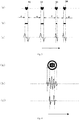
- Fig. 2 (c) is schematic diagrams of machine-readable signals of the magnetic units shown in Fig. 2 (a) .
- the letter 201 and the number 202 produced by the prior art can generate pulse signals 221 and 222, wherein the magnetic signal width a2 of the pulse signal 221 is the same as the width of the letter 201, and the magnetic signal width b2 of the pulse signal 222 is the same as the width of the number 202.
- the letter 203 and the number 204 of the magnetic unit provided by the embodiment of the present invention can generate pulse signals 223 and 224, wherein the magnetic signal width c2 of the pulse signal 223 is smaller than the width of the letter 203 and is the same as the width of the dark region in the cross-sectional view 213, and the magnetic signal width d2 of the pulse signal 224 is smaller than the width of the number 204 and is the same as the width of the dark region in the cross-sectional view 214.
- the pulse signal generated by the magnetic unit provided by the embodiment of the present invention is more suitable for machine-reading.
- Fig. 3 (a) is schematic diagrams of magnetic units composed of heart-shaped patterns in the prior art and an embodiment of the present invention, respectively.
- the heart-shaped patterns 31, 32, 33 and 34 of the Fig. 3 (a) are the same in size and shape, wherein the heart-shaped patterns 31 and 32 are magnetic units manufactured by the prior art, and the heart-shaped patterns 33 and 34 are magnetic units provided by the embodiment of the present invention.
- Fig. 3 (c) is schematic diagrams of machine-readable signals of the magnetic units shown in Fig. 3 (a) .
- the magnetic signal widths of the pulse signals generated by the heart-shaped patterns 31 and 32 are equal to the widths e of the heart-shaped patterns 31 and 32, wherein the magnetic signal widths of the pulse signals generated by the heart-shaped patterns 33 and 34 are f and g, respectively, which are smaller than the visual widths e of the heart-shaped patterns 33 and 34.
- the magnetic signal widths f and g generated by the heart-shaped patterns 33 and 34 provided by the embodiment of the present invention may vary with the changes in the width of the region with a large magnetic content in the heart-shaped pattern.
- Fig. 3 (b) is schematic diagrams of bar or block-shaped magnetic codes produced by the prior art
- Fig. 3 (c) is schematic diagrams of machine-readable signals of the bar or block-shaped magnetic codes shown in Fig. 3 (b)
- the machine-readable signal generated by each of the bar or block-shaped magnetic codes in Fig. 3 (b) corresponds to the machine-readable signal generated by each of the heart-shaped patterns in Fig. 3 (a) .
- the Fig. 3 (a) can provide both visual anti-counterfeiting features and machine-readable anti-counterfeiting features, while the Fig. 3 (b) is less aesthetically pleasing and more suitable for providing machine-readable anti-counterfeiting features only.
- the bar or block-shaped magnetic codes shown in the Fig. 3 (b) can be hidden in a security document through a metal layer or an opaque ink layer, such as, the application mode in the security thread of Euro and Pound Sterling bills.
- Fig. 4 (a) is a schematic diagram of a magnetic unit with a larger area.
- Fig. 4 (b) shows the pulse signal generated when machine-reading is performed on the magnetic unit manufactured by the prior art as shown in the Fig. 4 (a) in the direction of the arrow, and it can be seen from the figure that the pulse signal has more clutter peaks and is not conducive to quantitative machine-reading.
- Fig. 4 (c) shows the pulse signal generated when machine-reading is performed on the magnetic unit of the embodiment of the present invention as shown in Fig. 4 (a) in the direction of the arrow, wherein the pulse signal is formed by the region with a large magnetic content, and it can be seen from the figure that the peak interval of the pulse signal is clear and is suitable for quantitative machine-reading.
- Fig. 5 is a schematic diagram of a security element provided by an embodiment of the present invention applied to a magnetic icon. As shown in Fig. 5 , when the security element provided by the embodiment of the present invention is applied to a magnetic icon, it can provide both visual anti-counterfeiting features and machine-readable anti-counterfeiting features.
- Fig. 6 is a schematic diagram of a security element provided by an embodiment of the present invention applied to a security thread.
- the magnetic units can be periodically arranged on the base material, and the letter and number type magnetic units shown in the figure are used for illustration only and are not intended to limit the present invention.
- the security thread can be elongated, and can be implanted into paper as a security element.
- the security thread can also be printed directly onto the base material of the security documents. It can be seen from the figure that the security element provided by the embodiment of the present invention can also provide both visual anti-counterfeiting features and machine-readable anti-counterfeiting features when applied to a security thread.
- Fig. 7 is a structural schematic diagram of a security element provided by an embodiment of the present invention applied to a security thread in a hidden manner.
- a first cover layer covers on the magnetic unit layer of the security element
- a second cover layer covers under the magnetic unit layer of the security element
- the first cover layer and the second cover layer are adhered to various articles such as banknotes through a first adhesive and a second adhesive.
- the second cover layer covers on the base material, but it should be understood that the second cover layer may also cover under the base material depending on the particular application or the needs of the actual application.
- the second cover layer may be, such as, a metal plating layer or covering ink, but the present invention is not limited thereto.
- the security element provided by the present invention can be used for making security threads, wide strips, labels, markers, etc., or can be directly printed on security documents or adhered to various articles by various bonding mechanisms, such as printing on polymer banknotes or transferring to high security products and high value-added products, such as banknotes and credit cards.
- the present invention provides a security product comprising the above-mentioned security element.
- the security element can be provided in the security product in an embedded or windowed manner.
- the security product comprises, but is not limited to one of the following: banknotes, bank bills, tickets, certificates, documents or credit cards, and so on.
- the security element provided by the embodiment of the present invention has simple production process and high anti-counterfeiting performance, and can be well integrated in the design of valuable documents as a part of the graphic design of the valuable documents.
Landscapes
- Engineering & Computer Science (AREA)
- Physics & Mathematics (AREA)
- General Physics & Mathematics (AREA)
- Theoretical Computer Science (AREA)
- Artificial Intelligence (AREA)
- Computer Vision & Pattern Recognition (AREA)
- Computer Security & Cryptography (AREA)
- Manufacturing & Machinery (AREA)
- Business, Economics & Management (AREA)
- Accounting & Taxation (AREA)
- Finance (AREA)
- Credit Cards Or The Like (AREA)
Description
- The present invention relates to the technical field of anti-counterfeiting, and particularly relates to a security element and a security product.
- Most of the valuable documents contain security elements made of magnetic materials, such as magnetic icons, magnetic security threads or strips. The magnetic materials can be applied to the security elements continuously or in some areas of the security elements, for example, in the form of a magnetic icon or magnetic code.
- In order to improve the anti-counterfeiting level of security elements, the patent application of
CN102971748A has proposed a method for forming a magnetic code region by using two or more materials with different coercivity, wherein the magnetic unit formed by the two materials has a certain imperceptibility to the magnetic code and has higher anti-counterfeiting performance, but the printing overprinting of the two materials has high production difficulty, and the security element can be recognized only through special detection equipment. -
WO 2006/042667 A1 (GIESECKE & DEVRIENT GMBH [DE]; SCHUETZMANN JUERGEN [DE] ET AL.) 27 April 2006 relates to a security element comprising at least two magnetic materials that are provided with a different coercive field intensity while being applied to and/or inserted into the security element in such a way that the remanence thereof is the same. -
WO 03/002355 A1 (GIESECKE & DEVRIENT GMBH [DE]; HEIM MANFRED [DE]) 9 January 2003 -
WO 2014/161674 A1 (MANTEGAZZA A ARTI GRAFICI [IT]) 12 April 1989 relates to a security element having a magnetic coding composed of magnetic elements. - An object of the present invention is to provide a security element and a security product, wherein the security element has better imperceptibility to magnetic code and higher anti-counterfeiting performance. Printing production is simpler due to no need of high-precision overprinting, and the security element can be recognized through universal detection equipment.
- In order to achieve the above object, the present invention provides a security element, comprising: a base material; and one or more magnetic units located on the base material, wherein a magnetic signal width of at least a first magnetic unit of the one or more magnetic units is smaller than the visual width of the first magnetic unit.
- Optionally, the one or more magnetic units are made of one magnetic material.
- Optionally, the material is magnetically conductive ink.
- Optionally, a magnetic content of at least a first region of the first magnetic unit is greater than a magnetic content of remaining regions of the first magnetic unit.
- Optionally, the one or more magnetic units are periodically arranged on the base material.
- Optionally, each of the one or more magnetic units is one or more of the following: letters, numbers, words and/or patterns.
- Optionally, the magnetic regions of the one or more magnetic units have optical opacity.
- Accordingly, the present invention further provides a security product, which comprises the above-mentioned security element.
- Through the above technical solution, the magnetic signal width generated by a magnetic sensor for at least one magnetic unit in the security element is smaller than the visual width of the magnetic unit, and the authenticity of the security element can be easily detected by this feature, thus improving the anti-counterfeiting performance of the security element and having better imperceptibility to magnetic code, meanwhile, the security element can achieve batch production easily and can be recognized by a commercially available currency detector.
- Other characteristics and advantages of the present invention will be described in detail in the following detailed description.
- The drawings are intended to provide a further understanding of the present invention, are a part of the description, are intended to explain the present invention together with the following specific embodiments, but do not constitute a limitation to the present invention.
- In the drawings:
-
Fig. 1 is a schematic diagram of a magnetic unit exemplified by the letter "B"; -
Fig. 2 (a) is schematic diagrams of magnetic units composed of letters and numbers in the prior art and an embodiment of the present invention, respectively; -
Fig. 2 (b) is cross-sectional views of the magnetic units shown inFig. 2 (a) in the direction of the broken line and the arrow; -
Fig. 2 (c) is schematic diagrams of machine-readable signals of the magnetic units shown inFig. 2 (a) ; -
Fig. 3 (a) is schematic diagrams of magnetic units composed of heart-shaped patterns in the prior art and an embodiment of the present invention, respectively; -
Fig. 3 (b) is schematic diagrams of bar or block-shaped magnetic codes produced by the prior art; -
Fig. 3 (c) is schematic diagrams of machine-readable signals of the magnetic units shown inFig. 3 (a) and the bar or block-shaped magnetic codes shown inFig. 3 (b) ; -
Fig. 4 (a) is a schematic diagram of a magnetic unit with a larger area; -
Fig. 4 (b) and Fig. 4 (c) are schematic diagrams of machine-readable signals of the magnetic unit shown inFig. 4 (a) corresponding to the prior art and an embodiment of the present invention, respectively; -
Fig. 5 is a schematic diagram of a security element provided by an embodiment of the present invention applied to a magnetic icon; -
Fig. 6 is a schematic diagram of a security element provided by an embodiment of the present invention applied to a security thread; and -
Fig. 7 is a structural schematic diagram of a security element provided by an embodiment of the present invention applied to a security thread in a hidden manner. - The detailed description of the present invention will be described in detail by combining the following drawings. It should be understood that the detailed embodiments described herein are merely used for illustrating and explaining, but not restricting the present invention. Besides, those skilled in the art should appreciate that the gray scale and dimensional proportion in all of the drawings are merely illustrative and do not represent the actual color and dimensional proportion.
- The "first" and "second" referred in the embodiment of the present invention are merely used for descriptive purposes and are not to be interpreted as indicating or implying a relative importance or implicitly indicating the number of the indicated technical characteristics.
- The embodiment of the present invention provides a security element as defined in
claim 1. - A pulse signal corresponding to the magnetic unit can be obtained when the security element is detected by a magnetic sensor. A distance between a wave peak and a wave trough of the pulse signal corresponding to edges of a region capable of generating a pulse signal in the magnetic unit is defined as a magnetic signal width. The security element provided by the embodiment of the present invention at least has one magnetic unit, wherein the magnetic signal width corresponding to the magnetic unit is smaller than the visual width of the magnetic unit, so that the pulse signal will not be reproduced depending on the appearance characteristics of the security element, thereby improving the anti-counterfeiting performance of the security element. Moreover, the anti-counterfeiting performance of the security element can be detected easily, for example, the authenticity of the security element can be recognized by a commercially available currency detector, and the security element has low production difficulty and is easy for batch production.
- Optionally, the one or more magnetic units may be made of one kind of magnetic material, for example, the material can be conductive ink. The magnetic unit is made of one kind of material, therefore, it can be made by one-step printing, has simple manufacturing process, and greatly reduces the production difficulty and manufacturing cost of the security element. Optionally, the magnetic signal width may be made smaller than the visual width of the magnetic unit by controlling the ink contents of different regions of the magnetic unit. When the security element is detected by a magnetic sensor, the width of the machine-readable identifiable region is only the same as the width of the region of the portion with a larger magnetic content, therefore, the magnetic signal width may be made smaller than the visual width of the magnetic unit by setting the magnetic content of at least one region of the magnetic unit larger than that of the remaining regions.
- The magnetic unit can be one or more of the following: letters, numbers, words and/or patterns. Optionally, the magnetic unit can be periodically or aperiodically arranged on the base material.
-
Fig. 1 is a schematic diagram of a magnetic unit exemplified by the letter "B". As shown inFig. 1 , the magnetic content of the left portion of the letter "B" is larger than that of the right portion, but the letter "B" is uniformly opaque as a whole under the visual effect. When machine-reading is performed on the letter "B" in the direction of the arrow, the generated magnetic signal width c1 is smaller than the visual width a1 of the letter "B". It should be understood that the letter "B" is used herein for illustration only and is not intended to limit the present invention. -
Fig. 2 (a) is schematic diagrams of magnetic units composed of letters and numbers in the prior art and an embodiment of the present invention, respectively. As shown inFig. 2 (a) , theletter 201 and thenumber 202 are two magnetic units made by the prior art, and theletter 203 and thenumber 204 are magnetic units provided by the embodiment of the present invention. As seen fromFig. 2 (a) , theletters numbers -
Fig. 2 (b) is cross-sectional views of the magnetic units shown inFig. 2 (a) in the direction of the broken line and the arrow. Thecross-sectional views letter 201 and thenumber 202 produced by using the prior art have the same magnetic content, wherein the same magnetic ink is used during the production and they have the same plate-making parameters. The dark and light regions in thecross-sectional views -
Fig. 2 (c) is schematic diagrams of machine-readable signals of the magnetic units shown inFig. 2 (a) . When machine-reading is performed on the magnetic unit in the direction of the arrow in the figure, theletter 201 and thenumber 202 produced by the prior art can generatepulse signals pulse signal 221 is the same as the width of theletter 201, and the magnetic signal width b2 of thepulse signal 222 is the same as the width of thenumber 202. Theletter 203 and thenumber 204 of the magnetic unit provided by the embodiment of the present invention can generatepulse signals pulse signal 223 is smaller than the width of theletter 203 and is the same as the width of the dark region in thecross-sectional view 213, and the magnetic signal width d2 of thepulse signal 224 is smaller than the width of thenumber 204 and is the same as the width of the dark region in thecross-sectional view 214. The pulse signal generated by the magnetic unit provided by the embodiment of the present invention is more suitable for machine-reading. -
Fig. 3 (a) is schematic diagrams of magnetic units composed of heart-shaped patterns in the prior art and an embodiment of the present invention, respectively. The heart-shapedpatterns Fig. 3 (a) are the same in size and shape, wherein the heart-shapedpatterns patterns -
Fig. 3 (c) is schematic diagrams of machine-readable signals of the magnetic units shown inFig. 3 (a) . As shown inFig. 3 (c) , when .the magnetic units are detected by a magnetic sensor in the direction of the arrow in the figure, the magnetic signal widths of the pulse signals generated by the heart-shapedpatterns patterns patterns patterns patterns -
Fig. 3 (b) is schematic diagrams of bar or block-shaped magnetic codes produced by the prior art, andFig. 3 (c) is schematic diagrams of machine-readable signals of the bar or block-shaped magnetic codes shown inFig. 3 (b) . The machine-readable signal generated by each of the bar or block-shaped magnetic codes inFig. 3 (b) corresponds to the machine-readable signal generated by each of the heart-shaped patterns inFig. 3 (a) . However, in practical applications, for example, when an elongated security thread is manufactured, theFig. 3 (a) can provide both visual anti-counterfeiting features and machine-readable anti-counterfeiting features, while theFig. 3 (b) is less aesthetically pleasing and more suitable for providing machine-readable anti-counterfeiting features only. - As for one example application shown in the
Fig. 3 (b) , the bar or block-shaped magnetic codes shown in theFig. 3 (b) can be hidden in a security document through a metal layer or an opaque ink layer, such as, the application mode in the security thread of Euro and Pound Sterling bills. -
Fig. 4 (a) is a schematic diagram of a magnetic unit with a larger area.Fig. 4 (b) shows the pulse signal generated when machine-reading is performed on the magnetic unit manufactured by the prior art as shown in theFig. 4 (a) in the direction of the arrow, and it can be seen from the figure that the pulse signal has more clutter peaks and is not conducive to quantitative machine-reading.Fig. 4 (c) shows the pulse signal generated when machine-reading is performed on the magnetic unit of the embodiment of the present invention as shown inFig. 4 (a) in the direction of the arrow, wherein the pulse signal is formed by the region with a large magnetic content, and it can be seen from the figure that the peak interval of the pulse signal is clear and is suitable for quantitative machine-reading. -
Fig. 5 is a schematic diagram of a security element provided by an embodiment of the present invention applied to a magnetic icon. As shown inFig. 5 , when the security element provided by the embodiment of the present invention is applied to a magnetic icon, it can provide both visual anti-counterfeiting features and machine-readable anti-counterfeiting features. -
Fig. 6 is a schematic diagram of a security element provided by an embodiment of the present invention applied to a security thread. As shown inFig. 6 , the magnetic units can be periodically arranged on the base material, and the letter and number type magnetic units shown in the figure are used for illustration only and are not intended to limit the present invention. The security thread can be elongated, and can be implanted into paper as a security element. The security thread can also be printed directly onto the base material of the security documents. It can be seen from the figure that the security element provided by the embodiment of the present invention can also provide both visual anti-counterfeiting features and machine-readable anti-counterfeiting features when applied to a security thread. -
Fig. 7 is a structural schematic diagram of a security element provided by an embodiment of the present invention applied to a security thread in a hidden manner. As shown inFig. 7 , in the structural schematic diagram of the security thread, a first cover layer covers on the magnetic unit layer of the security element, a second cover layer covers under the magnetic unit layer of the security element, and the first cover layer and the second cover layer are adhered to various articles such as banknotes through a first adhesive and a second adhesive. In the example ofFig. 7 , the second cover layer covers on the base material, but it should be understood that the second cover layer may also cover under the base material depending on the particular application or the needs of the actual application. Here, the second cover layer may be, such as, a metal plating layer or covering ink, but the present invention is not limited thereto. - The security element provided by the present invention can be used for making security threads, wide strips, labels, markers, etc., or can be directly printed on security documents or adhered to various articles by various bonding mechanisms, such as printing on polymer banknotes or transferring to high security products and high value-added products, such as banknotes and credit cards.
- On the other hand, the present invention provides a security product comprising the above-mentioned security element. Optionally, the security element can be provided in the security product in an embedded or windowed manner. The security product comprises, but is not limited to one of the following: banknotes, bank bills, tickets, certificates, documents or credit cards, and so on.
- The security element provided by the embodiment of the present invention has simple production process and high anti-counterfeiting performance, and can be well integrated in the design of valuable documents as a part of the graphic design of the valuable documents.
- The preferred embodiments of the present invention have been described in detail by combining the drawings, however, the present invention is not limited to the specific details of the embodiments described above, and various modifications may be made to the technical solution of the present invention within the scope of the technical ideas of the present invention, in which all of these simple modifications belong to the scope of the present invention.
- It should be further noted that each technical feature described in the above specific embodiments may be combined in any appropriate way under the condition of no contradiction. To avoid unnecessary repetition, any possible combinations will not be specified separately in the present invention.
Claims (8)
- A security element, comprising:a base material; andone or more magnetic units located on the base material,characterized in that,a magnetic signal width (c2, d2, f, g) of at least a first magnetic unit (203, 204, 33, 34) of the one or more magnetic units is smaller than a visual width of the first magnetic unit (203, 204, 33, 34), and the first magnetic unit (203, 204, 33, 34) is uniformly opaque as a whole, wherein the magnetic signal width (c2, d2, f, g) is defined as a distance between a wave peak and a wave trough of the pulse signal detected by a magnetic sensor and corresponding to edges of a region capable of generating a pulse signal in the magnetic unit.
- The security element of claim 1, characterized in that the one or more magnetic units are made of one kind of magnetic material.
- The security element of claim 2, characterized in that the material is magnetically conductive ink.
- The security element of claim 1, characterized in that a magnetic content of at least a first region of the first magnetic unit (203, 204, 33, 34) is greater than a magnetic content of the remaining regions of the first magnetic unit.
- The security element of any one of claims 1-4, characterized in that the one or more magnetic units are periodically arranged on the base material.
- The security element of any one of claims 1-4, characterized in that each of the one or more magnetic units is one or more of the following: letters, numbers, words and/or patterns.
- The security element of any one of claims 1-4, characterized in that magnetic regions of the one or more magnetic units have optical opacity.
- A security product, characterized in comprising the security element of any one of claims 1-7.
Applications Claiming Priority (2)
| Application Number | Priority Date | Filing Date | Title |
|---|---|---|---|
| CN201611122526.2A CN106599966B (en) | 2016-12-08 | 2016-12-08 | Anti-counterfeiting element and anti-counterfeiting product |
| PCT/CN2017/112253 WO2018103528A1 (en) | 2016-12-08 | 2017-11-22 | Anti-counterfeiting element and anti-counterfeiting product |
Publications (3)
| Publication Number | Publication Date |
|---|---|
| EP3553706A1 EP3553706A1 (en) | 2019-10-16 |
| EP3553706A4 EP3553706A4 (en) | 2020-08-05 |
| EP3553706B1 true EP3553706B1 (en) | 2021-12-22 |
Family
ID=58597516
Family Applications (1)
| Application Number | Title | Priority Date | Filing Date |
|---|---|---|---|
| EP17877547.4A Active EP3553706B1 (en) | 2016-12-08 | 2017-11-22 | Anti-counterfeiting element and anti-counterfeiting product |
Country Status (4)
| Country | Link |
|---|---|
| EP (1) | EP3553706B1 (en) |
| CN (1) | CN106599966B (en) |
| AU (1) | AU2017373147B2 (en) |
| WO (1) | WO2018103528A1 (en) |
Families Citing this family (4)
| Publication number | Priority date | Publication date | Assignee | Title |
|---|---|---|---|---|
| CN106599966B (en) * | 2016-12-08 | 2020-04-28 | 中钞特种防伪科技有限公司 | Anti-counterfeiting element and anti-counterfeiting product |
| CN110744948B (en) * | 2018-07-24 | 2021-06-18 | 中钞特种防伪科技有限公司 | Magnetic anti-counterfeiting element and anti-counterfeiting product using same |
| DE102018128433A1 (en) | 2018-11-08 | 2020-05-14 | Technische Universität Wien | Method for processing a component having an information area, component with an information area and measuring system |
| CN115147977B (en) * | 2021-03-30 | 2023-12-22 | 深圳怡化电脑股份有限公司 | Paper money discriminating method, paper money discriminating device, electronic equipment and storage medium |
Citations (18)
| Publication number | Priority date | Publication date | Assignee | Title |
|---|---|---|---|---|
| EP0310707A2 (en) | 1987-10-08 | 1989-04-12 | MANTEGAZZA ANTONIO ARTI GRAFICHE S.r.l. | Document with magnetically detectable anti-forgery means, and strip with magnetically detectable identification code and identification code |
| WO1992011142A1 (en) | 1990-12-20 | 1992-07-09 | Gao Gesellschaft Fúr Automation Und Organisation Mbh | Magnetic metallic security thread with negative inscription |
| WO1997023357A1 (en) | 1995-12-22 | 1997-07-03 | Giesecke & Devrient Gmbh | Security document with a security component and method for the production thereof |
| EP0914970A2 (en) | 1997-11-11 | 1999-05-12 | MANTEGAZZA ANTONIO ARTI GRAFICHE S.r.l. | Security strip with optical and magnetic information |
| US6073845A (en) | 1995-12-19 | 2000-06-13 | Canon Denshi Kabushiki Kaisha | Recording medium on which information is recorded in intermittent pattern, and method of and apparatus for reproducing the information |
| WO2003002355A1 (en) | 2001-06-28 | 2003-01-09 | Giesecke & Devrient Gmbh | Security element |
| WO2004062943A2 (en) | 2003-01-10 | 2004-07-29 | De La Rue International Limited | Security thread |
| JP2005268655A (en) | 2004-03-19 | 2005-09-29 | National Printing Bureau | Magnetic printed matter |
| DE102004049999A1 (en) | 2004-10-14 | 2006-04-20 | Giesecke & Devrient Gmbh | security element |
| JP2009000832A (en) | 2007-06-19 | 2009-01-08 | National Printing Bureau | Forgery-proof printed matter |
| WO2009027771A1 (en) | 2007-08-28 | 2009-03-05 | Fabriano Securities S.R.L. | Security element particularly for banknotes, security cards and the like |
| WO2010006767A2 (en) | 2008-07-17 | 2010-01-21 | Giesecke & Devrient Gmbh | Data carrier comprising a printed magnetic security feature |
| US20100219245A1 (en) | 2007-06-04 | 2010-09-02 | Giesecke & Devrient Gmbh | Security element for securing documents of value |
| US20100238205A1 (en) | 2009-03-20 | 2010-09-23 | Christopher William Thomson | Method for Inkjet Printing of E13B Magnetic Ink Character Recognition Characters and Substrate Having Such Characters Printed Thereon |
| US20110096368A1 (en) | 2009-09-16 | 2011-04-28 | James Maher | Security system for printed material |
| WO2012000568A1 (en) | 2010-07-01 | 2012-01-05 | Fabriano Securities S.R.L. | Magnetic coding system with deposit of magnetic areas produced by at least two magnetic ink types with different coercitive fields, deposited in an at least partial overlay |
| WO2012175212A1 (en) | 2011-06-22 | 2012-12-27 | Giesecke & Devrient Gmbh | Magnetic screen printing ink or flexographic ink and security element printed using the same |
| WO2014161674A1 (en) | 2013-04-04 | 2014-10-09 | Giesecke & Devrient Gmbh | Security element for value documents |
Family Cites Families (3)
| Publication number | Priority date | Publication date | Assignee | Title |
|---|---|---|---|---|
| CN1280768C (en) * | 2003-06-19 | 2006-10-18 | 中国印钞造币总公司 | Magnetic encoding safety line |
| KR101238198B1 (en) * | 2012-09-14 | 2013-02-28 | 한국조폐공사 | Magnetic security feature having 3d moving hidden image effect and the printing method thereof |
| CN106599966B (en) * | 2016-12-08 | 2020-04-28 | 中钞特种防伪科技有限公司 | Anti-counterfeiting element and anti-counterfeiting product |
-
2016
- 2016-12-08 CN CN201611122526.2A patent/CN106599966B/en active Active
-
2017
- 2017-11-22 WO PCT/CN2017/112253 patent/WO2018103528A1/en unknown
- 2017-11-22 AU AU2017373147A patent/AU2017373147B2/en active Active
- 2017-11-22 EP EP17877547.4A patent/EP3553706B1/en active Active
Patent Citations (19)
| Publication number | Priority date | Publication date | Assignee | Title |
|---|---|---|---|---|
| EP0310707A2 (en) | 1987-10-08 | 1989-04-12 | MANTEGAZZA ANTONIO ARTI GRAFICHE S.r.l. | Document with magnetically detectable anti-forgery means, and strip with magnetically detectable identification code and identification code |
| WO1992011142A1 (en) | 1990-12-20 | 1992-07-09 | Gao Gesellschaft Fúr Automation Und Organisation Mbh | Magnetic metallic security thread with negative inscription |
| US6073845A (en) | 1995-12-19 | 2000-06-13 | Canon Denshi Kabushiki Kaisha | Recording medium on which information is recorded in intermittent pattern, and method of and apparatus for reproducing the information |
| WO1997023357A1 (en) | 1995-12-22 | 1997-07-03 | Giesecke & Devrient Gmbh | Security document with a security component and method for the production thereof |
| EP0914970A2 (en) | 1997-11-11 | 1999-05-12 | MANTEGAZZA ANTONIO ARTI GRAFICHE S.r.l. | Security strip with optical and magnetic information |
| WO2003002355A1 (en) | 2001-06-28 | 2003-01-09 | Giesecke & Devrient Gmbh | Security element |
| DE10131153A1 (en) | 2001-06-28 | 2003-01-16 | Giesecke & Devrient Gmbh | security element |
| WO2004062943A2 (en) | 2003-01-10 | 2004-07-29 | De La Rue International Limited | Security thread |
| JP2005268655A (en) | 2004-03-19 | 2005-09-29 | National Printing Bureau | Magnetic printed matter |
| DE102004049999A1 (en) | 2004-10-14 | 2006-04-20 | Giesecke & Devrient Gmbh | security element |
| US20100219245A1 (en) | 2007-06-04 | 2010-09-02 | Giesecke & Devrient Gmbh | Security element for securing documents of value |
| JP2009000832A (en) | 2007-06-19 | 2009-01-08 | National Printing Bureau | Forgery-proof printed matter |
| WO2009027771A1 (en) | 2007-08-28 | 2009-03-05 | Fabriano Securities S.R.L. | Security element particularly for banknotes, security cards and the like |
| WO2010006767A2 (en) | 2008-07-17 | 2010-01-21 | Giesecke & Devrient Gmbh | Data carrier comprising a printed magnetic security feature |
| US20100238205A1 (en) | 2009-03-20 | 2010-09-23 | Christopher William Thomson | Method for Inkjet Printing of E13B Magnetic Ink Character Recognition Characters and Substrate Having Such Characters Printed Thereon |
| US20110096368A1 (en) | 2009-09-16 | 2011-04-28 | James Maher | Security system for printed material |
| WO2012000568A1 (en) | 2010-07-01 | 2012-01-05 | Fabriano Securities S.R.L. | Magnetic coding system with deposit of magnetic areas produced by at least two magnetic ink types with different coercitive fields, deposited in an at least partial overlay |
| WO2012175212A1 (en) | 2011-06-22 | 2012-12-27 | Giesecke & Devrient Gmbh | Magnetic screen printing ink or flexographic ink and security element printed using the same |
| WO2014161674A1 (en) | 2013-04-04 | 2014-10-09 | Giesecke & Devrient Gmbh | Security element for value documents |
Also Published As
| Publication number | Publication date |
|---|---|
| AU2017373147A1 (en) | 2019-07-25 |
| AU2017373147B2 (en) | 2021-01-14 |
| CN106599966A (en) | 2017-04-26 |
| WO2018103528A1 (en) | 2018-06-14 |
| EP3553706A1 (en) | 2019-10-16 |
| CN106599966B (en) | 2020-04-28 |
| EP3553706A4 (en) | 2020-08-05 |
Similar Documents
| Publication | Publication Date | Title |
|---|---|---|
| EP3553706B1 (en) | Anti-counterfeiting element and anti-counterfeiting product | |
| RU2114743C1 (en) | Protective fiber, document protected by such fiber, protected document manufacture method and method for controlling authenticity and read-out of coded information of protected document | |
| AU2012328331B2 (en) | Security element | |
| AU2006281282B2 (en) | Security devices for security substrates | |
| AU2011225930B2 (en) | Improvements in security substrates for security documents | |
| AU2017366399B2 (en) | Security Element and Security Product with Security Element | |
| KR101295719B1 (en) | Improvement in security elements | |
| CA2451548C (en) | Security element | |
| CN101243227A (en) | Security device for security substrates | |
| KR101029565B1 (en) | Security thread | |
| EP2414176B1 (en) | Security element comprising magnetic areas of different coercivities and a method for its manufacture | |
| CN111016494A (en) | Anti-counterfeiting element and anti-counterfeiting product | |
| CN112329903B (en) | Magnetic anti-counterfeiting element, product and manufacturing method thereof | |
| CN1188450A (en) | Articles employing magnetic security feature |
Legal Events
| Date | Code | Title | Description |
|---|---|---|---|
| STAA | Information on the status of an ep patent application or granted ep patent |
Free format text: STATUS: THE INTERNATIONAL PUBLICATION HAS BEEN MADE |
|
| PUAI | Public reference made under article 153(3) epc to a published international application that has entered the european phase |
Free format text: ORIGINAL CODE: 0009012 |
|
| STAA | Information on the status of an ep patent application or granted ep patent |
Free format text: STATUS: REQUEST FOR EXAMINATION WAS MADE |
|
| 17P | Request for examination filed |
Effective date: 20190705 |
|
| AK | Designated contracting states |
Kind code of ref document: A1 Designated state(s): AL AT BE BG CH CY CZ DE DK EE ES FI FR GB GR HR HU IE IS IT LI LT LU LV MC MK MT NL NO PL PT RO RS SE SI SK SM TR |
|
| AX | Request for extension of the european patent |
Extension state: BA ME |
|
| DAV | Request for validation of the european patent (deleted) | ||
| DAX | Request for extension of the european patent (deleted) | ||
| REG | Reference to a national code |
Ref country code: DE Ref legal event code: R079 Ref document number: 602017051399 Country of ref document: DE Free format text: PREVIOUS MAIN CLASS: G06K0019060000 Ipc: B42D0025369000 |
|
| A4 | Supplementary search report drawn up and despatched |
Effective date: 20200707 |
|
| RIC1 | Information provided on ipc code assigned before grant |
Ipc: G06K 19/06 20060101ALI20200701BHEP Ipc: B42D 25/23 20140101ALI20200701BHEP Ipc: B42D 25/405 20140101ALI20200701BHEP Ipc: B42D 25/373 20140101ALI20200701BHEP Ipc: B42D 25/29 20140101ALI20200701BHEP Ipc: B42D 25/369 20140101AFI20200701BHEP Ipc: G07D 7/004 20160101ALI20200701BHEP |
|
| STAA | Information on the status of an ep patent application or granted ep patent |
Free format text: STATUS: EXAMINATION IS IN PROGRESS |
|
| 17Q | First examination report despatched |
Effective date: 20210419 |
|
| GRAP | Despatch of communication of intention to grant a patent |
Free format text: ORIGINAL CODE: EPIDOSNIGR1 |
|
| STAA | Information on the status of an ep patent application or granted ep patent |
Free format text: STATUS: GRANT OF PATENT IS INTENDED |
|
| INTG | Intention to grant announced |
Effective date: 20210818 |
|
| GRAS | Grant fee paid |
Free format text: ORIGINAL CODE: EPIDOSNIGR3 |
|
| GRAA | (expected) grant |
Free format text: ORIGINAL CODE: 0009210 |
|
| STAA | Information on the status of an ep patent application or granted ep patent |
Free format text: STATUS: THE PATENT HAS BEEN GRANTED |
|
| AK | Designated contracting states |
Kind code of ref document: B1 Designated state(s): AL AT BE BG CH CY CZ DE DK EE ES FI FR GB GR HR HU IE IS IT LI LT LU LV MC MK MT NL NO PL PT RO RS SE SI SK SM TR |
|
| REG | Reference to a national code |
Ref country code: GB Ref legal event code: FG4D |
|
| REG | Reference to a national code |
Ref country code: CH Ref legal event code: EP |
|
| REG | Reference to a national code |
Ref country code: DE Ref legal event code: R096 Ref document number: 602017051399 Country of ref document: DE |
|
| REG | Reference to a national code |
Ref country code: AT Ref legal event code: REF Ref document number: 1456840 Country of ref document: AT Kind code of ref document: T Effective date: 20220115 |
|
| REG | Reference to a national code |
Ref country code: IE Ref legal event code: FG4D |
|
| REG | Reference to a national code |
Ref country code: LT Ref legal event code: MG9D |
|
| PG25 | Lapsed in a contracting state [announced via postgrant information from national office to epo] |
Ref country code: RS Free format text: LAPSE BECAUSE OF FAILURE TO SUBMIT A TRANSLATION OF THE DESCRIPTION OR TO PAY THE FEE WITHIN THE PRESCRIBED TIME-LIMIT Effective date: 20211222 Ref country code: LT Free format text: LAPSE BECAUSE OF FAILURE TO SUBMIT A TRANSLATION OF THE DESCRIPTION OR TO PAY THE FEE WITHIN THE PRESCRIBED TIME-LIMIT Effective date: 20211222 Ref country code: FI Free format text: LAPSE BECAUSE OF FAILURE TO SUBMIT A TRANSLATION OF THE DESCRIPTION OR TO PAY THE FEE WITHIN THE PRESCRIBED TIME-LIMIT Effective date: 20211222 Ref country code: BG Free format text: LAPSE BECAUSE OF FAILURE TO SUBMIT A TRANSLATION OF THE DESCRIPTION OR TO PAY THE FEE WITHIN THE PRESCRIBED TIME-LIMIT Effective date: 20220322 |
|
| REG | Reference to a national code |
Ref country code: NL Ref legal event code: MP Effective date: 20211222 |
|
| REG | Reference to a national code |
Ref country code: AT Ref legal event code: MK05 Ref document number: 1456840 Country of ref document: AT Kind code of ref document: T Effective date: 20211222 |
|
| PG25 | Lapsed in a contracting state [announced via postgrant information from national office to epo] |
Ref country code: SE Free format text: LAPSE BECAUSE OF FAILURE TO SUBMIT A TRANSLATION OF THE DESCRIPTION OR TO PAY THE FEE WITHIN THE PRESCRIBED TIME-LIMIT Effective date: 20211222 Ref country code: NO Free format text: LAPSE BECAUSE OF FAILURE TO SUBMIT A TRANSLATION OF THE DESCRIPTION OR TO PAY THE FEE WITHIN THE PRESCRIBED TIME-LIMIT Effective date: 20220322 Ref country code: LV Free format text: LAPSE BECAUSE OF FAILURE TO SUBMIT A TRANSLATION OF THE DESCRIPTION OR TO PAY THE FEE WITHIN THE PRESCRIBED TIME-LIMIT Effective date: 20211222 Ref country code: HR Free format text: LAPSE BECAUSE OF FAILURE TO SUBMIT A TRANSLATION OF THE DESCRIPTION OR TO PAY THE FEE WITHIN THE PRESCRIBED TIME-LIMIT Effective date: 20211222 Ref country code: GR Free format text: LAPSE BECAUSE OF FAILURE TO SUBMIT A TRANSLATION OF THE DESCRIPTION OR TO PAY THE FEE WITHIN THE PRESCRIBED TIME-LIMIT Effective date: 20220323 |
|
| PG25 | Lapsed in a contracting state [announced via postgrant information from national office to epo] |
Ref country code: NL Free format text: LAPSE BECAUSE OF FAILURE TO SUBMIT A TRANSLATION OF THE DESCRIPTION OR TO PAY THE FEE WITHIN THE PRESCRIBED TIME-LIMIT Effective date: 20211222 |
|
| PG25 | Lapsed in a contracting state [announced via postgrant information from national office to epo] |
Ref country code: SM Free format text: LAPSE BECAUSE OF FAILURE TO SUBMIT A TRANSLATION OF THE DESCRIPTION OR TO PAY THE FEE WITHIN THE PRESCRIBED TIME-LIMIT Effective date: 20211222 Ref country code: SK Free format text: LAPSE BECAUSE OF FAILURE TO SUBMIT A TRANSLATION OF THE DESCRIPTION OR TO PAY THE FEE WITHIN THE PRESCRIBED TIME-LIMIT Effective date: 20211222 Ref country code: RO Free format text: LAPSE BECAUSE OF FAILURE TO SUBMIT A TRANSLATION OF THE DESCRIPTION OR TO PAY THE FEE WITHIN THE PRESCRIBED TIME-LIMIT Effective date: 20211222 Ref country code: PT Free format text: LAPSE BECAUSE OF FAILURE TO SUBMIT A TRANSLATION OF THE DESCRIPTION OR TO PAY THE FEE WITHIN THE PRESCRIBED TIME-LIMIT Effective date: 20220422 Ref country code: ES Free format text: LAPSE BECAUSE OF FAILURE TO SUBMIT A TRANSLATION OF THE DESCRIPTION OR TO PAY THE FEE WITHIN THE PRESCRIBED TIME-LIMIT Effective date: 20211222 Ref country code: EE Free format text: LAPSE BECAUSE OF FAILURE TO SUBMIT A TRANSLATION OF THE DESCRIPTION OR TO PAY THE FEE WITHIN THE PRESCRIBED TIME-LIMIT Effective date: 20211222 Ref country code: CZ Free format text: LAPSE BECAUSE OF FAILURE TO SUBMIT A TRANSLATION OF THE DESCRIPTION OR TO PAY THE FEE WITHIN THE PRESCRIBED TIME-LIMIT Effective date: 20211222 |
|
| PG25 | Lapsed in a contracting state [announced via postgrant information from national office to epo] |
Ref country code: PL Free format text: LAPSE BECAUSE OF FAILURE TO SUBMIT A TRANSLATION OF THE DESCRIPTION OR TO PAY THE FEE WITHIN THE PRESCRIBED TIME-LIMIT Effective date: 20211222 Ref country code: AT Free format text: LAPSE BECAUSE OF FAILURE TO SUBMIT A TRANSLATION OF THE DESCRIPTION OR TO PAY THE FEE WITHIN THE PRESCRIBED TIME-LIMIT Effective date: 20211222 |
|
| REG | Reference to a national code |
Ref country code: DE Ref legal event code: R026 Ref document number: 602017051399 Country of ref document: DE |
|
| PLBI | Opposition filed |
Free format text: ORIGINAL CODE: 0009260 |
|
| PG25 | Lapsed in a contracting state [announced via postgrant information from national office to epo] |
Ref country code: IS Free format text: LAPSE BECAUSE OF FAILURE TO SUBMIT A TRANSLATION OF THE DESCRIPTION OR TO PAY THE FEE WITHIN THE PRESCRIBED TIME-LIMIT Effective date: 20220422 |
|
| PLAX | Notice of opposition and request to file observation + time limit sent |
Free format text: ORIGINAL CODE: EPIDOSNOBS2 |
|
| 26 | Opposition filed |
Opponent name: GIESECKE+DEVRIENT CURRENCY TECHNOLOGY GMBH Effective date: 20220919 Opponent name: HUECK FOLIEN GESELLSCHAFT M.B.H. Effective date: 20220916 |
|
| PG25 | Lapsed in a contracting state [announced via postgrant information from national office to epo] |
Ref country code: DK Free format text: LAPSE BECAUSE OF FAILURE TO SUBMIT A TRANSLATION OF THE DESCRIPTION OR TO PAY THE FEE WITHIN THE PRESCRIBED TIME-LIMIT Effective date: 20211222 Ref country code: AL Free format text: LAPSE BECAUSE OF FAILURE TO SUBMIT A TRANSLATION OF THE DESCRIPTION OR TO PAY THE FEE WITHIN THE PRESCRIBED TIME-LIMIT Effective date: 20211222 |
|
| PLBB | Reply of patent proprietor to notice(s) of opposition received |
Free format text: ORIGINAL CODE: EPIDOSNOBS3 |
|
| PG25 | Lapsed in a contracting state [announced via postgrant information from national office to epo] |
Ref country code: SI Free format text: LAPSE BECAUSE OF FAILURE TO SUBMIT A TRANSLATION OF THE DESCRIPTION OR TO PAY THE FEE WITHIN THE PRESCRIBED TIME-LIMIT Effective date: 20211222 |
|
| REG | Reference to a national code |
Ref country code: DE Ref legal event code: R119 Ref document number: 602017051399 Country of ref document: DE |
|
| PG25 | Lapsed in a contracting state [announced via postgrant information from national office to epo] |
Ref country code: MC Free format text: LAPSE BECAUSE OF FAILURE TO SUBMIT A TRANSLATION OF THE DESCRIPTION OR TO PAY THE FEE WITHIN THE PRESCRIBED TIME-LIMIT Effective date: 20211222 |
|
| REG | Reference to a national code |
Ref country code: CH Ref legal event code: PL |
|
| REG | Reference to a national code |
Ref country code: BE Ref legal event code: MM Effective date: 20221130 |
|
| PG25 | Lapsed in a contracting state [announced via postgrant information from national office to epo] |
Ref country code: LI Free format text: LAPSE BECAUSE OF NON-PAYMENT OF DUE FEES Effective date: 20221130 Ref country code: CH Free format text: LAPSE BECAUSE OF NON-PAYMENT OF DUE FEES Effective date: 20221130 |
|
| PG25 | Lapsed in a contracting state [announced via postgrant information from national office to epo] |
Ref country code: LU Free format text: LAPSE BECAUSE OF NON-PAYMENT OF DUE FEES Effective date: 20221122 |
|
| PG25 | Lapsed in a contracting state [announced via postgrant information from national office to epo] |
Ref country code: IE Free format text: LAPSE BECAUSE OF NON-PAYMENT OF DUE FEES Effective date: 20221122 Ref country code: DE Free format text: LAPSE BECAUSE OF NON-PAYMENT OF DUE FEES Effective date: 20230601 |
|
| PG25 | Lapsed in a contracting state [announced via postgrant information from national office to epo] |
Ref country code: FR Free format text: LAPSE BECAUSE OF NON-PAYMENT OF DUE FEES Effective date: 20221130 Ref country code: BE Free format text: LAPSE BECAUSE OF NON-PAYMENT OF DUE FEES Effective date: 20221130 |
|
| PGFP | Annual fee paid to national office [announced via postgrant information from national office to epo] |
Ref country code: GB Payment date: 20231123 Year of fee payment: 7 |
|
| PGFP | Annual fee paid to national office [announced via postgrant information from national office to epo] |
Ref country code: IT Payment date: 20231130 Year of fee payment: 7 |
|
| RDAF | Communication despatched that patent is revoked |
Free format text: ORIGINAL CODE: EPIDOSNREV1 |
|
| PG25 | Lapsed in a contracting state [announced via postgrant information from national office to epo] |
Ref country code: HU Free format text: LAPSE BECAUSE OF FAILURE TO SUBMIT A TRANSLATION OF THE DESCRIPTION OR TO PAY THE FEE WITHIN THE PRESCRIBED TIME-LIMIT; INVALID AB INITIO Effective date: 20171122 |
|
| PG25 | Lapsed in a contracting state [announced via postgrant information from national office to epo] |
Ref country code: CY Free format text: LAPSE BECAUSE OF FAILURE TO SUBMIT A TRANSLATION OF THE DESCRIPTION OR TO PAY THE FEE WITHIN THE PRESCRIBED TIME-LIMIT Effective date: 20211222 |
|
| APBP | Date of receipt of notice of appeal recorded |
Free format text: ORIGINAL CODE: EPIDOSNNOA2O |
|
| APAH | Appeal reference modified |
Free format text: ORIGINAL CODE: EPIDOSCREFNO |
|
| APAW | Appeal reference deleted |
Free format text: ORIGINAL CODE: EPIDOSDREFNO |