EP3553551B1 - Method for the recognition of an object - Google Patents
Method for the recognition of an object Download PDFInfo
- Publication number
- EP3553551B1 EP3553551B1 EP18166530.8A EP18166530A EP3553551B1 EP 3553551 B1 EP3553551 B1 EP 3553551B1 EP 18166530 A EP18166530 A EP 18166530A EP 3553551 B1 EP3553551 B1 EP 3553551B1
- Authority
- EP
- European Patent Office
- Prior art keywords
- accordance
- micro
- doppler
- periodic
- curve
- Prior art date
- Legal status (The legal status is an assumption and is not a legal conclusion. Google has not performed a legal analysis and makes no representation as to the accuracy of the status listed.)
- Active
Links
- 238000000034 method Methods 0.000 title claims description 56
- 230000000737 periodic effect Effects 0.000 claims description 41
- 230000033001 locomotion Effects 0.000 claims description 15
- 238000012545 processing Methods 0.000 claims description 11
- 230000003044 adaptive effect Effects 0.000 claims description 10
- 238000004458 analytical method Methods 0.000 claims description 10
- 238000009826 distribution Methods 0.000 claims description 5
- 230000011218 segmentation Effects 0.000 claims description 5
- 238000004590 computer program Methods 0.000 claims description 3
- 230000001186 cumulative effect Effects 0.000 description 9
- 238000005315 distribution function Methods 0.000 description 7
- 230000001419 dependent effect Effects 0.000 description 4
- 230000000694 effects Effects 0.000 description 4
- 230000005021 gait Effects 0.000 description 4
- 238000001514 detection method Methods 0.000 description 3
- 238000012905 input function Methods 0.000 description 2
- 238000005259 measurement Methods 0.000 description 2
- 241001465754 Metazoa Species 0.000 description 1
- 230000001133 acceleration Effects 0.000 description 1
- 238000007792 addition Methods 0.000 description 1
- 230000002411 adverse Effects 0.000 description 1
- 238000013459 approach Methods 0.000 description 1
- 230000001747 exhibiting effect Effects 0.000 description 1
- 230000004927 fusion Effects 0.000 description 1
- 238000009499 grossing Methods 0.000 description 1
- 238000005286 illumination Methods 0.000 description 1
- 238000004519 manufacturing process Methods 0.000 description 1
- 238000007620 mathematical function Methods 0.000 description 1
- 238000004540 process dynamic Methods 0.000 description 1
- 239000007787 solid Substances 0.000 description 1
Images
Classifications
-
- G—PHYSICS
- G01—MEASURING; TESTING
- G01S—RADIO DIRECTION-FINDING; RADIO NAVIGATION; DETERMINING DISTANCE OR VELOCITY BY USE OF RADIO WAVES; LOCATING OR PRESENCE-DETECTING BY USE OF THE REFLECTION OR RERADIATION OF RADIO WAVES; ANALOGOUS ARRANGEMENTS USING OTHER WAVES
- G01S13/00—Systems using the reflection or reradiation of radio waves, e.g. radar systems; Analogous systems using reflection or reradiation of waves whose nature or wavelength is irrelevant or unspecified
- G01S13/88—Radar or analogous systems specially adapted for specific applications
- G01S13/89—Radar or analogous systems specially adapted for specific applications for mapping or imaging
- G01S13/90—Radar or analogous systems specially adapted for specific applications for mapping or imaging using synthetic aperture techniques, e.g. synthetic aperture radar [SAR] techniques
- G01S13/9021—SAR image post-processing techniques
- G01S13/9027—Pattern recognition for feature extraction
-
- G—PHYSICS
- G01—MEASURING; TESTING
- G01S—RADIO DIRECTION-FINDING; RADIO NAVIGATION; DETERMINING DISTANCE OR VELOCITY BY USE OF RADIO WAVES; LOCATING OR PRESENCE-DETECTING BY USE OF THE REFLECTION OR RERADIATION OF RADIO WAVES; ANALOGOUS ARRANGEMENTS USING OTHER WAVES
- G01S13/00—Systems using the reflection or reradiation of radio waves, e.g. radar systems; Analogous systems using reflection or reradiation of waves whose nature or wavelength is irrelevant or unspecified
- G01S13/02—Systems using reflection of radio waves, e.g. primary radar systems; Analogous systems
- G01S13/50—Systems of measurement based on relative movement of target
- G01S13/58—Velocity or trajectory determination systems; Sense-of-movement determination systems
- G01S13/589—Velocity or trajectory determination systems; Sense-of-movement determination systems measuring the velocity vector
-
- G—PHYSICS
- G01—MEASURING; TESTING
- G01S—RADIO DIRECTION-FINDING; RADIO NAVIGATION; DETERMINING DISTANCE OR VELOCITY BY USE OF RADIO WAVES; LOCATING OR PRESENCE-DETECTING BY USE OF THE REFLECTION OR RERADIATION OF RADIO WAVES; ANALOGOUS ARRANGEMENTS USING OTHER WAVES
- G01S13/00—Systems using the reflection or reradiation of radio waves, e.g. radar systems; Analogous systems using reflection or reradiation of waves whose nature or wavelength is irrelevant or unspecified
- G01S13/02—Systems using reflection of radio waves, e.g. primary radar systems; Analogous systems
- G01S13/50—Systems of measurement based on relative movement of target
- G01S13/505—Systems of measurement based on relative movement of target using Doppler effect for determining closest range to a target or corresponding time, e.g. miss-distance indicator
-
- G—PHYSICS
- G01—MEASURING; TESTING
- G01S—RADIO DIRECTION-FINDING; RADIO NAVIGATION; DETERMINING DISTANCE OR VELOCITY BY USE OF RADIO WAVES; LOCATING OR PRESENCE-DETECTING BY USE OF THE REFLECTION OR RERADIATION OF RADIO WAVES; ANALOGOUS ARRANGEMENTS USING OTHER WAVES
- G01S13/00—Systems using the reflection or reradiation of radio waves, e.g. radar systems; Analogous systems using reflection or reradiation of waves whose nature or wavelength is irrelevant or unspecified
- G01S13/02—Systems using reflection of radio waves, e.g. primary radar systems; Analogous systems
- G01S13/50—Systems of measurement based on relative movement of target
- G01S13/58—Velocity or trajectory determination systems; Sense-of-movement determination systems
- G01S13/62—Sense-of-movement determination
-
- G—PHYSICS
- G01—MEASURING; TESTING
- G01S—RADIO DIRECTION-FINDING; RADIO NAVIGATION; DETERMINING DISTANCE OR VELOCITY BY USE OF RADIO WAVES; LOCATING OR PRESENCE-DETECTING BY USE OF THE REFLECTION OR RERADIATION OF RADIO WAVES; ANALOGOUS ARRANGEMENTS USING OTHER WAVES
- G01S13/00—Systems using the reflection or reradiation of radio waves, e.g. radar systems; Analogous systems using reflection or reradiation of waves whose nature or wavelength is irrelevant or unspecified
- G01S13/88—Radar or analogous systems specially adapted for specific applications
- G01S13/89—Radar or analogous systems specially adapted for specific applications for mapping or imaging
- G01S13/90—Radar or analogous systems specially adapted for specific applications for mapping or imaging using synthetic aperture techniques, e.g. synthetic aperture radar [SAR] techniques
- G01S13/9004—SAR image acquisition techniques
- G01S13/9017—SAR image acquisition techniques with time domain processing of the SAR signals in azimuth
-
- G—PHYSICS
- G01—MEASURING; TESTING
- G01S—RADIO DIRECTION-FINDING; RADIO NAVIGATION; DETERMINING DISTANCE OR VELOCITY BY USE OF RADIO WAVES; LOCATING OR PRESENCE-DETECTING BY USE OF THE REFLECTION OR RERADIATION OF RADIO WAVES; ANALOGOUS ARRANGEMENTS USING OTHER WAVES
- G01S13/00—Systems using the reflection or reradiation of radio waves, e.g. radar systems; Analogous systems using reflection or reradiation of waves whose nature or wavelength is irrelevant or unspecified
- G01S13/88—Radar or analogous systems specially adapted for specific applications
- G01S13/89—Radar or analogous systems specially adapted for specific applications for mapping or imaging
- G01S13/90—Radar or analogous systems specially adapted for specific applications for mapping or imaging using synthetic aperture techniques, e.g. synthetic aperture radar [SAR] techniques
- G01S13/9021—SAR image post-processing techniques
- G01S13/9029—SAR image post-processing techniques specially adapted for moving target detection within a single SAR image or within multiple SAR images taken at the same time
-
- G—PHYSICS
- G01—MEASURING; TESTING
- G01S—RADIO DIRECTION-FINDING; RADIO NAVIGATION; DETERMINING DISTANCE OR VELOCITY BY USE OF RADIO WAVES; LOCATING OR PRESENCE-DETECTING BY USE OF THE REFLECTION OR RERADIATION OF RADIO WAVES; ANALOGOUS ARRANGEMENTS USING OTHER WAVES
- G01S13/00—Systems using the reflection or reradiation of radio waves, e.g. radar systems; Analogous systems using reflection or reradiation of waves whose nature or wavelength is irrelevant or unspecified
- G01S13/88—Radar or analogous systems specially adapted for specific applications
- G01S13/93—Radar or analogous systems specially adapted for specific applications for anti-collision purposes
- G01S13/931—Radar or analogous systems specially adapted for specific applications for anti-collision purposes of land vehicles
-
- G—PHYSICS
- G01—MEASURING; TESTING
- G01S—RADIO DIRECTION-FINDING; RADIO NAVIGATION; DETERMINING DISTANCE OR VELOCITY BY USE OF RADIO WAVES; LOCATING OR PRESENCE-DETECTING BY USE OF THE REFLECTION OR RERADIATION OF RADIO WAVES; ANALOGOUS ARRANGEMENTS USING OTHER WAVES
- G01S7/00—Details of systems according to groups G01S13/00, G01S15/00, G01S17/00
- G01S7/02—Details of systems according to groups G01S13/00, G01S15/00, G01S17/00 of systems according to group G01S13/00
- G01S7/41—Details of systems according to groups G01S13/00, G01S15/00, G01S17/00 of systems according to group G01S13/00 using analysis of echo signal for target characterisation; Target signature; Target cross-section
- G01S7/415—Identification of targets based on measurements of movement associated with the target
-
- G—PHYSICS
- G01—MEASURING; TESTING
- G01S—RADIO DIRECTION-FINDING; RADIO NAVIGATION; DETERMINING DISTANCE OR VELOCITY BY USE OF RADIO WAVES; LOCATING OR PRESENCE-DETECTING BY USE OF THE REFLECTION OR RERADIATION OF RADIO WAVES; ANALOGOUS ARRANGEMENTS USING OTHER WAVES
- G01S13/00—Systems using the reflection or reradiation of radio waves, e.g. radar systems; Analogous systems using reflection or reradiation of waves whose nature or wavelength is irrelevant or unspecified
- G01S13/88—Radar or analogous systems specially adapted for specific applications
- G01S13/93—Radar or analogous systems specially adapted for specific applications for anti-collision purposes
- G01S13/931—Radar or analogous systems specially adapted for specific applications for anti-collision purposes of land vehicles
- G01S2013/9327—Sensor installation details
- G01S2013/93271—Sensor installation details in the front of the vehicles
-
- G—PHYSICS
- G06—COMPUTING; CALCULATING OR COUNTING
- G06F—ELECTRIC DIGITAL DATA PROCESSING
- G06F2218/00—Aspects of pattern recognition specially adapted for signal processing
- G06F2218/02—Preprocessing
- G06F2218/04—Denoising
- G06F2218/06—Denoising by applying a scale-space analysis, e.g. using wavelet analysis
-
- G—PHYSICS
- G06—COMPUTING; CALCULATING OR COUNTING
- G06F—ELECTRIC DIGITAL DATA PROCESSING
- G06F2218/00—Aspects of pattern recognition specially adapted for signal processing
- G06F2218/12—Classification; Matching
- G06F2218/14—Classification; Matching by matching peak patterns
Definitions
- the present invention relates to a method for the recognition of an object by means of a radar sensor system, wherein a primary radar signal is transmitted into an observation space, a secondary radar signal reflected by the object is received, a Micro-Doppler spectrogram of the secondary radar signal is generated, and at least one periodicity quantity relating to an at least essentially periodic motion of a part of the object is determined based on the Micro-Doppler spectrogram.
- Radar sensor systems are used in a wide range of applications. For example, modern motor vehicles are often equipped with radar sensor systems to detect other vehicles, obstacles or vulnerable road users such as pedestrians or cyclists. A detection and classification of objects in a traffic space from a host vehicle is in particular needed for various advanced driver assistance systems (ADAS), such as advanced emergency braking (AEB) systems, adaptive cruise control (ACC) systems and autonomous driving systems.
- ADAS advanced driver assistance systems
- AEB advanced emergency braking
- ACC adaptive cruise control
- autonomous driving systems autonomous driving systems.
- the Doppler effect or Doppler shift is a change in frequency observed when a wave source moves relative to the receiver.
- the Doppler frequency shift mainly results from the movement of the observed object as a whole, i.e. in case of an observed pedestrian from the movement of the pedestrian's torso and in case of an observed cyclist from the movement of the frame of the bike. Beside this shift resulting from the main body movement, there usually are sidebands relating to moving parts of the object. For example, swinging arms or legs of a pedestrian as well as rotating wheels or pedals of a bike can cause additional Doppler shifts. Such additional shifts are discernible in a Micro-Doppler spectrogram.
- a Micro-Doppler spectrogram of the secondary radar signal is generated for a predefined period of time which is called "observation period".
- the generation of Micro-Doppler spectrograms is disclosed, for example, in the book of Chen V.C., "The Micro-Doppler Effect in Radar", Artech House, 2011 , or in the paper of Yan et al., "Micro-Doppler Based Classifying Features for Automotive Radar VRU Target Classification", 25th International Technical Conference on the Enhanced Safety of Vehicles (ESV), June 5-8, 2017, Detroit, Michigan, United States .
- Micro-Doppler-signature The superposition of Doppler shifts from each individual component is called a "Micro-Doppler-signature". Micro-Doppler-signatures can be analyzed to classify detected objects. The use of Doppler spectrograms for a discrimination of pedestrians is disclosed, for example, in the paper of Gürbüz S.Z. et al., "Detection and Identification of Human Targets in Radar Data", SPIE 6567, Signal Processing, Sensor Fusion and Target Recognition XVI, 65670I, May 2007 .
- the at least one periodicity quantity can be an average cycle duration, an average repetition frequency or a number of time bins related to one period or cycle of the pattern.
- the periodicity quantity is characteristic for the pedestrian's gait cycle. One gait cycle usually corresponds to two footsteps.
- Fourier analyses generally rely on the assumption that the speed of the observed object is constant. This assumption, however, is violated in many cases. For example, a pedestrian might suddenly slow down or even stop. A Fourier analysis is not adequate for such situations.
- a method in accordance with the preamble of claim 1 is disclosed in CN 104 360 336 A .
- the determining of the at least one periodicity quantity includes the steps:
- the repetition frequency the period or a similar quantity.
- the period can be determined as the distance between two consecutive peaks or valleys.
- a periodic pattern in a Micro-Doppler spectrogram is a series of similar features being spaced apart from one another.
- a periodic pattern is a spectrogram structure that has an essentially periodic appearance and thus contains periodic information.
- a periodic pattern is not necessarily periodic in a strict mathematical sense.
- signal components that correspond to periodic patterns of a Micro-Doppler spectrogram likewise are not periodic in a strict mathematical sense. Rather, such signal components contain periodic information, but have a strongly fluctuating course exhibiting numerous local peaks and valleys. It is thus difficult to directly obtain the periodic information from the course of a raw signal component extracted from the spectrogram. By fitting a smoothed curve to the signal component, however, it is possible to estimate the real maxima and minima.
- the smoothed curve can be fitted to the periodic signal component by means of an adaptive curve-fitting process.
- an adaptive curve-fitting process is able to adapt itself to varying conditions.
- a corresponding curve-fitting process is particularly robust.
- At least one process parameter of the adaptive curve-fitting process is continuously adapted during the curve-fitting process. Variations of the process dynamics can thus be compensated.
- the process parameter is adapted based on a determined speed variation of the object.
- a determined speed variation of the object can be handled.
- the speed of the object can be captured or measured, preferably by means of the radar sensor system.
- the speed can be determined based on a-priori-information.
- step (i) the courses over time of an upper envelope, a lower envelope and a difference between an upper envelope and a lower envelope of the Micro-Doppler spectrogram are determined as courses over time of periodic signal components.
- These signal components are relatively easy to be extracted from the spectrogram.
- strong radar reflection components like a pedestrian's torso signal or a cyclist's pedal or wheel signal can be determined as periodic signal components.
- step (ii) the fitting of the smoothed curve to the periodic signal component can be performed using a window function, in particular using a triangle kernel, a polynomial kernel, or a Savitzky-Golay kernel.
- a window function is a mathematical function that is zero-valued outside of a predefined interval.
- the window size of the window function is continuously adapted during the fitting of the smoothed curve to the periodic signal component. This has turned out to provide particularly robust results.
- the window size is adapted in dependence on the speed of the object and/or a speed variation of the object. Dependent on the application, the observed speed or the actual speed may be used.
- the Micro-Doppler spectrogram may be generated by means of a time-frequency analysis, in particular by means of a Short-Time-Fourier-Transform (STFT) or a Wigner-Ville-Distribution technique (WVD technique).
- STFT Short-Time-Fourier-Transform
- WVD technique Wigner-Ville-Distribution technique
- the secondary radar signal or a signal derived from the secondary radar signal may be subjected to a time-frequency analysis.
- Either the secondary radar signal itself or a signal derived from the secondary radar signal may be subjected to the time-frequency analysis.
- the step (iii) can include a segmentation process, wherein the first peak of a sequence of peaks is defined as a starting position of a segment and/or the last peak of a sequence of peaks is defined as an ending position of a segment.
- Objects can be classified more reliably if the borders of individual pattern segments are known.
- the periodicity quantity can be estimated by means of a recursive state estimator, in particular a Kalman Filter.
- a recursive state estimator By means of a recursive state estimator, it is possible to achieve particularly reliable results.
- the recursive state estimator may use a state vector including the speed of the object and the length of a motion cycle.
- the step (i) includes determining a spread measure of the Micro-Doppler spectogram, the spread measure being the difference between an upper envelope and a lower envelope of the Micro-Doppler spectrogram.
- the periodic signal component can be determined by means of a percentile-based method or a curve-fitting method. Specifically, it is possible to calculate the cumulative amplitude distribution for each time slice and to determine the upper envelope to correspond to a percentile of about 95% of the cumulative amplitude distribution function and/or to determine the lower envelope to correspond to a percentile of about 5% of the cumulative amplitude distribution function. It is also possible to calculate the cumulative amplitude distribution for each time slice and to determine the observed object speed to correspond to a percentile of about 50% of the cumulative amplitude distribution function. According to an embodiment of the invention, a percentile-based method or a curve-fitting method as disclosed in the paper of Gürbüz S.Z. et al., "Operational assessment and adaptive selection of micro-Doppler features", IET Radar Sonar Navig., Vol. 9, Iss. 9, pp. 1196-1204, 2015 , may be used to determine the observed object speed.
- the invention also relates to a system for the recognition of an object comprising a radar sensor system for transmitting a primary radar signal into an observation space and for receiving a secondary radar signal reflected by the object and an electronic processing device for processing the secondary radar signal.
- the electronic processing device is configured for carrying out a method as disclosed above.
- the electronic processing device may be united with the radar sensor system or configured as a separate unit.
- the electronic processing device may comprise a computer.
- the radar sensor system is configured to be mounted at or in a motor vehicle.
- the invention further relates to a computer program product including executable program code which, when executed, carries out a method as disclosed above.
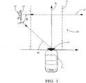
- a motor vehicle 11 and a radar sensor system 13 mounted to a front section of the motor vehicle 11.
- the radar sensor system 13 is preferably based on a millimeter wave radar sensor.
- a single channel radar sensor may be provided to minimize the production costs, while a multiple channel radar sensor may be provided to enhance the detection performance.
- the radar sensor system 13 can be connected to an electronic processing device (not shown), for example an advanced emergency braking system, a pedestrian collision avoidance system or an autonomous driving system. While a central mounting of the radar sensor system 13 is shown, a mounting to a corner section, a side section or a rear section of the motor vehicle 11 could equally be provided.
- the motor vehicle 11 is moving in a driving direction 15 on a lane 17.
- An object 19 in the form of a pedestrian crossing the lane 17 is present in the traffic space 23 in front of the motor vehicle 11.
- the object 19 is moving in a moving direction 21.
- Other examples of objects to be observed by the radar sensor system 13 are cyclists and vehicles.
- the radar sensor system 13 is configured for transmitting a primary radar signal into the traffic space 23 and for detecting objects 19 present in the traffic space 23 on the basis of a secondary radar signal reflected by the objects 19.
- the line 25 which extends from the object 19 to the active region of the radar sensor system 13 is called "line of sight".
- the observed bulk speed v ob of the object 19, i. e. the speed component related to the main body 27 of the object 19 and oriented along the line of sight 25, can be determined in a known manner using the Doppler effect.
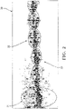
- FIG. 2 An exemplary Micro-Doppler spectrogram 30 of a moving cyclist is shown in Fig. 2 .
- the horizontal axis is a time axis, whereas the vertical axis is a Doppler shift axis or a radial velocity axis.
- the generation of the Micro-Doppler spectrogram 30 can be carried out by means of a Short-Time-Fourier-Transform (STFT) or a Wigner-Ville-Distribution technique (WVD technique).
- STFT Short-Time-Fourier-Transform
- WVD technique Wigner-Ville-Distribution technique
- a Micro-Doppler spectrogram of a pedestrian, a motor vehicle or a helicopter includes similar Micro-Doppler patterns that correspond to a gait cycle of the pedestrian, a wheel rotation of the motor vehicle or a rotor blade movement of the helicopter, respectively.
- the Micro-Doppler patterns 31, 32 caused by these motions are at least essentially periodic.
- the periodicity quantity can be an average cycle duration, an average repetition frequency or a number of time bins related to one period or cycle of the corresponding pattern. In case of a pedestrian, the periodicity quantity is characteristic for the pedestrian's gait cycle.
- a periodicity quantity relating to an at least essentially periodic motion of a part of the object 19 is determined on the basis of a Micro-Doppler spectrogram analysis by means of the electronic processing device, as is explained in greater detail below.
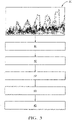
- a Micro-Doppler spectrogram 30 is generated as an input for the subsequent steps.
- a step 41 the course of a periodic signal component corresponding to a Micro-Doppler pattern 31, 32 is determined.
- a spread measure of the signal component is estimated.
- a smoothed curve is fitted to the periodic signal component by means of an adaptive curve-fitting process.
- the positions of the peaks and/or valleys of the smoothed curve are determined.
- a periodicity quantity is determined based on the determined positions of the peaks and valleys.
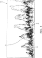
- Fig. 4 shows an exemplary Micro-Doppler spectrogram 30' of a pedestrian in an enlarged view.
- Three curves corresponding to the courses of different motion components are shown in the Micro-Doppler spectrogram 30'.
- the course 50 of the observed bulk speed v ob is shown as a solid black line
- the upper envelope 51 of the Micro-Doppler spectrogram 30' and the lower envelope 52 of the Micro-Doppler spectrogram 30' are shown as dashed lines.
- the cumulative amplitude distribution function is determined for each time slice.
- the course 50 of the observed bulk speed v ob is assigned to a percentile of about 50% of the cumulative amplitude distribution function.
- the upper envelope 51 is assigned to a percentile of about 95% of the cumulative amplitude distribution function, whereas the lower envelope 52 is assigned to a percentile of about 5% of the cumulative amplitude distribution function.
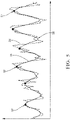
- FIG. 5 An exemplary course 54 of E diff over time is shown in Fig. 5 .
- a smoothed curve 55 fitted to this course 54 in step 43 ( Fig. 3 ) is equally shown.
- the window size used in the adaptive curve-fitting process is adapted to the variation of the observed bulk speed v ob .
- a preferred value for L 0 cycle is 1.4 m, since the typical gait-cycle of a pedestrian is around 1.2 m - 1.6 m, whereas a preferred value for V 0 is 1.5 m/s.
- the adaptive curve fitting process in step 43 is carried out by means of a kernel function.
- a kernel function is selected that smooths the raw signal so as to remove high frequency components while simultaneously maintaining the peak magnitude levels.
- Preferred kernel functions are high-order least-square polynomial kernels and high-order Savitzky-Golay kernels. According to a specific embodiment, a 2 nd order or a 3 rd order kernel is selected.
- step 44 a peak finding process is performed to find the peaks 57 of the smoothed curve 55.
- peaks 57 are determined that satisfy the following conditions:
- the valleys 58 of the smoothed curve 55 can be found in an analogous manner.
- T n cycle N n cycle ⁇ ⁇ t
- the period T n cycle and the repetition frequency f n cycle of the corresponding Micro-Doppler pattern 31, 32 can be determined.
- the duration between two consecutive peaks 57 or valleys 58 is the duration of one footstep cycle.
- a gait-cycle includes two footsteps.
- a recursive state estimator in particular a Kalman filter
- the random variables w n-1 and q n represent the process noise and the measurement noise.
- the subscripts n , n-1 indicate the current state and the previous state, respectively.
- the dot refers to the derivative of V.
- the peaks 57 found in the peak finding process can be used for a segmentation process, wherein the starting point and the ending point of the corresponding Micro-Doppler pattern 31, 32 are determined.
- the first peak 57 of a sequence of peaks 57 can be defined as a starting position of a segment, whereas the last peak 57 of a sequence of peaks 57 is defined as an ending position of a segment.
- the invention enables a reliable recognition of moving objects 19 by means of a radar sensor system 13 even in case the available observation time is rather short.
Description
- The present invention relates to a method for the recognition of an object by means of a radar sensor system, wherein a primary radar signal is transmitted into an observation space, a secondary radar signal reflected by the object is received, a Micro-Doppler spectrogram of the secondary radar signal is generated, and at least one periodicity quantity relating to an at least essentially periodic motion of a part of the object is determined based on the Micro-Doppler spectrogram.
- Radar sensor systems are used in a wide range of applications. For example, modern motor vehicles are often equipped with radar sensor systems to detect other vehicles, obstacles or vulnerable road users such as pedestrians or cyclists. A detection and classification of objects in a traffic space from a host vehicle is in particular needed for various advanced driver assistance systems (ADAS), such as advanced emergency braking (AEB) systems, adaptive cruise control (ACC) systems and autonomous driving systems.
- Often, the known Doppler effect is used to gather information relating to moving objects. The Doppler effect or Doppler shift is a change in frequency observed when a wave source moves relative to the receiver. The Doppler frequency shift mainly results from the movement of the observed object as a whole, i.e. in case of an observed pedestrian from the movement of the pedestrian's torso and in case of an observed cyclist from the movement of the frame of the bike. Beside this shift resulting from the main body movement, there usually are sidebands relating to moving parts of the object. For example, swinging arms or legs of a pedestrian as well as rotating wheels or pedals of a bike can cause additional Doppler shifts. Such additional shifts are discernible in a Micro-Doppler spectrogram. Generally, a Micro-Doppler spectrogram of the secondary radar signal is generated for a predefined period of time which is called "observation period". The generation of Micro-Doppler spectrograms is disclosed, for example, in the book of Chen V.C., "The Micro-Doppler Effect in Radar", Artech House, 2011, or in the paper of Yan et al., "Micro-Doppler Based Classifying Features for Automotive Radar VRU Target Classification", 25th International Technical Conference on the Enhanced Safety of Vehicles (ESV), June 5-8, 2017, Detroit, Michigan, United States.
- The superposition of Doppler shifts from each individual component is called a "Micro-Doppler-signature". Micro-Doppler-signatures can be analyzed to classify detected objects. The use of Doppler spectrograms for a discrimination of pedestrians is disclosed, for example, in the paper of Gürbüz S.Z. et al., "Detection and Identification of Human Targets in Radar Data", SPIE 6567, Signal Processing, Sensor Fusion and Target Recognition XVI, 65670I, May 2007.
- Since the above mentioned motions of arms, legs, wheels or other individual components usually are of an essentially periodic nature, they cause at least essentially periodic patterns in a Micro-Doppler spectrogram. By determining a periodicity quantity relating to such a pattern, it is possible do discriminate between different types of objects, for example between humans and vehicles or between humans and animals. The at least one periodicity quantity can be an average cycle duration, an average repetition frequency or a number of time bins related to one period or cycle of the pattern. In case of a pedestrian, the periodicity quantity is characteristic for the pedestrian's gait cycle. One gait cycle usually corresponds to two footsteps.
- To determine the repetition frequency of a pattern in a Micro-Doppler spectrogram, a Fourier analysis of the spectrogram can be carried out. However, this approach requires a relatively long observation time, which often is not available in real-world scenarios. In particular automotive applications require a comparatively short observation time.
- Moreover, Fourier analyses generally rely on the assumption that the speed of the observed object is constant. This assumption, however, is violated in many cases. For example, a pedestrian might suddenly slow down or even stop. A Fourier analysis is not adequate for such situations.
- It has also to be noted that a Fourier analysis is not convenient for a segmentation process, i. e. for finding the starting position and ending position of a pattern. In many applications, however, a reliable segmentation process is desired.
- For the above mentioned reasons, it is in practice difficult to correctly identify objects by means of a Micro-Doppler analysis.
- A method in accordance with the preamble of
claim 1 is disclosed inCN 104 360 336 A . - Methods for recognizing objects by means of radar sensors are also disclosed in
DE 10 2016 215102 A1 ,DE 10 2016 213254 B3 ,US 2017/057497 A1 ,DE 10 2015 007040 A1 ,US 4 958 638 A ,US 5 689 268 A and Gürbüz SZ et al.: "Operational assessment and adaptive selection of micro-Doppler features", IET Radar, Sonar & Navigation, UK, vol. 9, 1 December 2015, pages 1196-1204, XP006054619, ISSN: 1751-8784, DOI: 10.1049/IET-RSN.2015.0144. - It is an object of the invention to enable a reliable recognition of objects by means of a radar sensor system even under adverse circumstances.
- The object is satisfied in accordance with the invention by a method in accordance with
claim 1. - In accordance with the invention, the determining of the at least one periodicity quantity includes the steps:
- (i) determining the course of at least one periodic signal component corresponding to an at least essentially periodic pattern of the Micro-Doppler spectrogram,
- (ii) fitting a smoothed curve to the periodic signal component,
- (iii) determining the positions of a plurality of peaks and/or valleys of the smoothed curve, and
- (iv) determining the periodicity quantity based on the determined positions of peaks and/or valleys.
- By means of a method in accordance with the invention, it is possible to reliably identify periodic motion components of an observed object even in case the speed of the object varies. A long observation time is not required.
- If the positions of the peaks and/or valleys of the smoothed curve are known, it is relatively easy to estimate the repetition frequency, the period or a similar quantity. For example, the period can be determined as the distance between two consecutive peaks or valleys.
- A periodic pattern in a Micro-Doppler spectrogram is a series of similar features being spaced apart from one another. In the context of the present disclosure, a periodic pattern is a spectrogram structure that has an essentially periodic appearance and thus contains periodic information. However, a periodic pattern is not necessarily periodic in a strict mathematical sense.
- Therefore, signal components that correspond to periodic patterns of a Micro-Doppler spectrogram likewise are not periodic in a strict mathematical sense. Rather, such signal components contain periodic information, but have a strongly fluctuating course exhibiting numerous local peaks and valleys. It is thus difficult to directly obtain the periodic information from the course of a raw signal component extracted from the spectrogram. By fitting a smoothed curve to the signal component, however, it is possible to estimate the real maxima and minima.
- Advantageous embodiments of the invention can be seen from the dependent claims, from the following description and from the appended figures.
- In the step (ii), the smoothed curve can be fitted to the periodic signal component by means of an adaptive curve-fitting process. Such a process is able to adapt itself to varying conditions. A corresponding curve-fitting process is particularly robust.
- According to an embodiment of the invention, at least one process parameter of the adaptive curve-fitting process is continuously adapted during the curve-fitting process. Variations of the process dynamics can thus be compensated.
- Preferably, the process parameter is adapted based on a determined speed variation of the object. Thus, situations like a sudden stop or a quick acceleration of the object can be handled. The speed of the object can be captured or measured, preferably by means of the radar sensor system. Alternatively, the speed can be determined based on a-priori-information.
- In step (i), the courses over time of an upper envelope, a lower envelope and a difference between an upper envelope and a lower envelope of the Micro-Doppler spectrogram are determined as courses over time of periodic signal components. These signal components are relatively easy to be extracted from the spectrogram. In principle, strong radar reflection components like a pedestrian's torso signal or a cyclist's pedal or wheel signal can be determined as periodic signal components.
- In step (ii), the fitting of the smoothed curve to the periodic signal component can be performed using a window function, in particular using a triangle kernel, a polynomial kernel, or a Savitzky-Golay kernel. Preferably, a high-order kernel is used. A window function is a mathematical function that is zero-valued outside of a predefined interval. By applying a window function to a strongly fluctuating input function, an effective smoothing of the input function can be achieved. In principle, the step (ii) can include applying a moving average filter to the periodic signal component.
- In accordance with an embodiment of the invention, the window size of the window function is continuously adapted during the fitting of the smoothed curve to the periodic signal component. This has turned out to provide particularly robust results. Preferably, the window size is adapted in dependence on the speed of the object and/or a speed variation of the object. Dependent on the application, the observed speed or the actual speed may be used.
- The Micro-Doppler spectrogram may be generated by means of a time-frequency analysis, in particular by means of a Short-Time-Fourier-Transform (STFT) or a Wigner-Ville-Distribution technique (WVD technique). Dependent on the application, the secondary radar signal or a signal derived from the secondary radar signal may be subjected to a time-frequency analysis. Either the secondary radar signal itself or a signal derived from the secondary radar signal may be subjected to the time-frequency analysis.
- The step (iii) can include a segmentation process, wherein the first peak of a sequence of peaks is defined as a starting position of a segment and/or the last peak of a sequence of peaks is defined as an ending position of a segment. Objects can be classified more reliably if the borders of individual pattern segments are known. In step (iv), the periodicity quantity can be estimated by means of a recursive state estimator, in particular a Kalman Filter. By means of a recursive state estimator, it is possible to achieve particularly reliable results. The recursive state estimator may use a state vector including the speed of the object and the length of a motion cycle.
- According to the embodiment of the invention, the step (i) includes determining a spread measure of the Micro-Doppler spectogram, the spread measure being the difference between an upper envelope and a lower envelope of the Micro-Doppler spectrogram.
- The periodic signal component can be determined by means of a percentile-based method or a curve-fitting method. Specifically, it is possible to calculate the cumulative amplitude distribution for each time slice and to determine the upper envelope to correspond to a percentile of about 95% of the cumulative amplitude distribution function and/or to determine the lower envelope to correspond to a percentile of about 5% of the cumulative amplitude distribution function. It is also possible to calculate the cumulative amplitude distribution for each time slice and to determine the observed object speed to correspond to a percentile of about 50% of the cumulative amplitude distribution function. According to an embodiment of the invention, a percentile-based method or a curve-fitting method as disclosed in the paper of Gürbüz S.Z. et al., "Operational assessment and adaptive selection of micro-Doppler features", IET Radar Sonar Navig., Vol. 9, Iss. 9, pp. 1196-1204, 2015, may be used to determine the observed object speed.
- The invention also relates to a system for the recognition of an object comprising a radar sensor system for transmitting a primary radar signal into an observation space and for receiving a secondary radar signal reflected by the object and an electronic processing device for processing the secondary radar signal. According to the invention, the electronic processing device is configured for carrying out a method as disclosed above.
- Dependent on the application, the electronic processing device may be united with the radar sensor system or configured as a separate unit. The electronic processing device may comprise a computer.
- Preferably, the radar sensor system is configured to be mounted at or in a motor vehicle.
- The invention further relates to a computer program product including executable program code which, when executed, carries out a method as disclosed above.
- The disclosure with reference to the inventive method is also true for the inventive system and the inventive computer program product.
- Subsequently, the present invention is explained in more detail based on an exemplary embodiment with reference to the accompanying figures, wherein:
- Fig. 1
- shows, in a top view, a motor vehicle, a radar sensor system mounted to the motor vehicle and a pedestrian to be detected by the radar sensor system;
- Fig. 2
- shows a Micro-Doppler spectrogram generated by the radar sensor system according to
Fig. 1 ; - Fig. 3
- is a flowchart showing different steps of a method according to an embodiment of the invention;
- Fig. 4
- shows an enlarged section of a Micro-Doppler spectrogram;
- Fig. 5
- shows the course of a periodic signal component corresponding to an at least essentially periodic pattern of a Micro-Doppler spectrogram as well as a smoothed curve fitted to the course.
- In
Fig. 1 , there is shown amotor vehicle 11 and aradar sensor system 13 mounted to a front section of themotor vehicle 11. Theradar sensor system 13 is preferably based on a millimeter wave radar sensor. A single channel radar sensor may be provided to minimize the production costs, while a multiple channel radar sensor may be provided to enhance the detection performance. Theradar sensor system 13 can be connected to an electronic processing device (not shown), for example an advanced emergency braking system, a pedestrian collision avoidance system or an autonomous driving system. While a central mounting of theradar sensor system 13 is shown, a mounting to a corner section, a side section or a rear section of themotor vehicle 11 could equally be provided. - In operation, the
motor vehicle 11 is moving in a drivingdirection 15 on alane 17. Anobject 19 in the form of a pedestrian crossing thelane 17 is present in thetraffic space 23 in front of themotor vehicle 11. Theobject 19 is moving in a movingdirection 21. Other examples of objects to be observed by theradar sensor system 13 are cyclists and vehicles. - The
radar sensor system 13 is configured for transmitting a primary radar signal into thetraffic space 23 and for detectingobjects 19 present in thetraffic space 23 on the basis of a secondary radar signal reflected by theobjects 19. Theline 25 which extends from theobject 19 to the active region of theradar sensor system 13 is called "line of sight". The observed bulk speed vob of theobject 19, i. e. the speed component related to themain body 27 of theobject 19 and oriented along the line ofsight 25, can be determined in a known manner using the Doppler effect. Specifically, it is known that the relationship between the observed bulk speed vob and the speed v of theobject 19 in the movingdirection 21 is given as:
direction 21 and the line ofsight 25. - An exemplary
Micro-Doppler spectrogram 30 of a moving cyclist is shown inFig. 2 . The horizontal axis is a time axis, whereas the vertical axis is a Doppler shift axis or a radial velocity axis. The generation of theMicro-Doppler spectrogram 30 can be carried out by means of a Short-Time-Fourier-Transform (STFT) or a Wigner-Ville-Distribution technique (WVD technique). In the left portion ofFig. 2 , there is indicated a firstMicro-Doppler pattern 31 that corresponds to a wheel rotation cycle. To the right of the firstMicro-Doppler pattern 31, there are several furtherMicro-Doppler patterns 32 that correspond to pedal rotation cycles. A Micro-Doppler spectrogram of a pedestrian, a motor vehicle or a helicopter includes similar Micro-Doppler patterns that correspond to a gait cycle of the pedestrian, a wheel rotation of the motor vehicle or a rotor blade movement of the helicopter, respectively. - Since the motions of individual components of an observed
object 19 like arms, legs, wheels, pedals or rotor blades usually are of an essentially periodic nature, theMicro-Doppler patterns Micro-Doppler pattern objects 19, for example between pedestrians and cyclists or between adults and children. The periodicity quantity can be an average cycle duration, an average repetition frequency or a number of time bins related to one period or cycle of the corresponding pattern. In case of a pedestrian, the periodicity quantity is characteristic for the pedestrian's gait cycle. - According to the invention, a periodicity quantity relating to an at least essentially periodic motion of a part of the
object 19 is determined on the basis of a Micro-Doppler spectrogram analysis by means of the electronic processing device, as is explained in greater detail below. - As shown in
Fig. 3 , aMicro-Doppler spectrogram 30 is generated as an input for the subsequent steps. In astep 41, the course of a periodic signal component corresponding to aMicro-Doppler pattern step 42, a spread measure of the signal component is estimated. In astep 43, a smoothed curve is fitted to the periodic signal component by means of an adaptive curve-fitting process. In astep 44, the positions of the peaks and/or valleys of the smoothed curve are determined. In astep 45, a periodicity quantity is determined based on the determined positions of the peaks and valleys. -
Fig. 4 shows an exemplary Micro-Doppler spectrogram 30' of a pedestrian in an enlarged view. Three curves corresponding to the courses of different motion components are shown in the Micro-Doppler spectrogram 30'. Specifically, thecourse 50 of the observed bulk speed vob is shown as a solid black line, whereas theupper envelope 51 of the Micro-Doppler spectrogram 30' and thelower envelope 52 of the Micro-Doppler spectrogram 30' are shown as dashed lines. - To determine the
course 50 of the observed bulk speed vob , theupper envelope 51 and thelower envelope 52, the cumulative amplitude distribution function is determined for each time slice. Thecourse 50 of the observed bulk speed vob is assigned to a percentile of about 50% of the cumulative amplitude distribution function. Theupper envelope 51 is assigned to a percentile of about 95% of the cumulative amplitude distribution function, whereas thelower envelope 52 is assigned to a percentile of about 5% of the cumulative amplitude distribution function. - The spread of the Micro-Doppler spectrogram 30' is estimated by determining the envelope difference Ediff , i. e. the absolute value of the difference between the
upper envelope 51 and the lower envelope 52:
- An
exemplary course 54 of Ediff over time is shown inFig. 5 . A smoothedcurve 55 fitted to thiscourse 54 in step 43 (Fig. 3 ) is equally shown. The window size used in the adaptive curve-fitting process is adapted to the variation of the observed bulk speed vob. According to an embodiment of the invention, the window size Nn win at the time tn is given as:
- The initial value of the window size can be set as:

Micro-Doppler spectrogram 30, 30', L0 cycle is the average length of the related periodic motion cycle and V0 is the average speed of theobject 19. In the context of the recognition of pedestrians, a preferred value for L0 cycle is 1.4 m, since the typical gait-cycle of a pedestrian is around 1.2 m - 1.6 m, whereas a preferred value for V0 is 1.5 m/s. - The adaptive curve fitting process in step 43 (
Fig. 3 ) is carried out by means of a kernel function. Preferably, a kernel function is selected that smooths the raw signal so as to remove high frequency components while simultaneously maintaining the peak magnitude levels. Preferred kernel functions are high-order least-square polynomial kernels and high-order Savitzky-Golay kernels. According to a specific embodiment, a 2nd order or a 3rd order kernel is selected. - In step 44 (
Fig. 3 ), a peak finding process is performed to find thepeaks 57 of the smoothedcurve 55. In particular, peaks 57 are determined that satisfy the following conditions: - It is a local peak, and
- the minimum distance between each two consecutive peaks is larger than k·Nn win, where k is a scale factor. Typical values for k range from 0.5 to 1, preferably from 0.7 to 0.9.
- The last mentioned condition increases the robustness of the peak finding process. Instead of the
peaks 57 or in additions to thepeaks 57, thevalleys 58 of the smoothedcurve 55 can be found in an analogous manner. - Supposing that Nn cycle is the number of samples contained in one cycle of a
Micro-Doppler pattern 
- The repetition frequency fn cycle of a
Micro-Doppler pattern 
- Once Nn cycle is determined, the period Tn cycle and the repetition frequency fn cycle of the corresponding
Micro-Doppler pattern - Supposing that Dn is the number of samples that are present between two
consecutive peaks 57 near time slice tn, the relationship between Dn and Nn cycle is Nn cycle = 2·Dn for pedestrians and Nn cycle = Dn for objects having rotating components such as bikes, motor vehicles or helicopters. - For pedestrians, the duration between two
consecutive peaks 57 orvalleys 58 is the duration of one footstep cycle. A gait-cycle includes two footsteps. - To further improve the robustness of the method according to the invention, a recursive state estimator, in particular a Kalman filter, can be used. In an algorithm based on a Kalman Filter, the state space model and the measurement model can be given as:


- The
peaks 57 found in the peak finding process can be used for a segmentation process, wherein the starting point and the ending point of the correspondingMicro-Doppler pattern first peak 57 of a sequence ofpeaks 57 can be defined as a starting position of a segment, whereas thelast peak 57 of a sequence ofpeaks 57 is defined as an ending position of a segment. - The invention enables a reliable recognition of moving
objects 19 by means of aradar sensor system 13 even in case the available observation time is rather short. -
- 11
- motor vehicle
- 13
- radar sensor system
- 15
- driving direction
- 17
- lane
- 19
- object
- 21
- moving direction
- 23
- traffic space
- 25
- line of sight
- 27
- main body
- 30, 30'
- Micro-Doppler spectrogram
- 31
- first Micro-Doppler pattern
- 32
- further Micro-Doppler pattern
- 41
- step of determining the course of a periodic signal component
- 42
- step of estimating a spread measure of the signal component
- 43
- step of fitting a smoothed curve to the signal component
- 44
- step of determining the positions of peaks and/or valleys
- 45
- step of determining a periodicity quantity
- 50
- course of the observed bulk speed
- 51
- upper envelope
- 52
- lower envelope
- 54
- course of envelope difference
- 55
- smoothed curve
- 57
- peak
- 58
- valley
Claims (12)
- A method for the recognition of an object (19) by means of a radar sensor system (13), whereina primary radar signal is transmitted into an observation space (23),a secondary radar signal reflected by the object (19) is received,a Micro-Doppler spectrogram (30, 30') of the secondary radar signal is generated, and at least one periodicity quantity relating to an at least essentially periodic motion of a part of the object (19) is determined based on the Micro-Doppler spectrogram (30, 30'),wherein the determining of the at least one periodicity quantity includes the steps:(i) determining the course over time of at least one periodic signal component (50, 51, 52, 54) corresponding to an at least essentially periodic pattern (31, 32) of the Micro-Doppler spectrogram (30, 30'),(ii) fitting a smoothed curve (55) to the at least one periodic signal component (50, 51, 52, 54),(iii) determining the positions of a plurality of peaks (57) and/or valleys (58) of the smoothed curve (55), and(iv) determining the periodicity quantity based on the determined positions of peaks (57) and/or valleys (58),characterized in thatin step (i), the courses over time of an upper envelope (51), a lower envelope (52) and a difference (54) between an upper envelope (51) and a lower envelope (52) of the Micro-Doppler spectrogram (30, 30') are determined as courses over time of periodic signal components.
- A method in accordance with claim 1,
characterized in that
in the step (ii), the smoothed curve (55) is fitted to the periodic signal component (50, 51, 52, 54) by means of an adaptive curve-fitting process. - A method in accordance with claim 2,
characterized in that
at least one process parameter of the adaptive curve-fitting process is continuously adapted during the curve-fitting process. - A method in accordance with claim 3,
characterized in that
the process parameter is adapted based on a determined speed variation of the object (19). - A method in accordance with any one of the preceding claims,
characterized in that
in step (ii), the fitting of the smoothed curve (55) to the periodic signal component (50, 51, 52, 54) is performed using a window function, in particular using a triangle kernel, a polynomial kernel or a Savitzky-Golay kernel. - A method in accordance with claim 5,
characterized in that
the window size of the window function is continuously adapted during the fitting of the smoothed curve (55) to the periodic signal component (50, 51, 52, 54). - A method in accordance with any one of the preceding claims,
characterized in that
the Micro-Doppler spectrogram (30, 30') is generated by means of a time-frequency analysis, in particular by means of a Short-Time-Fourier-Transform (STFT) or a Wigner-Ville-Distribution technique (WVD technique). - A method in accordance with any one of the preceding claims,
characterized in that
the step (iii) includes a segmentation process, wherein the first peak (57) of a sequence of peaks (57) is defined as a starting position of a segment and/or the last peak (57) of a sequence of peaks (57) is defined as an ending position of a segment. - A method in accordance with any one of the preceding claims,
characterized in that
in step (iv), the periodicity quantity is estimated by means of a recursive state estimator, in particular a Kalman Filter. - A system for the recognition of an object (19) comprisinga radar sensor system (13) for transmitting a primary radar signal into an observation space (23) and for receiving a secondary radar signal reflected by the object (19) andan electronic processing device for processing the secondary radar signal,characterized in that
the electronic processing device is configured for carrying out a method in accordance with any one of the preceding claims. - A system in accordance with claim 10,
characterized in that
the radar sensor system (13) is configured to be mounted at or in a motor vehicle (11). - A computer program product including executable program code which, when executed, causes a system in accordance with claim 10 or 11 to carry out a method in accordance with any one of claims 1 to 9.
Priority Applications (3)
| Application Number | Priority Date | Filing Date | Title |
|---|---|---|---|
| EP18166530.8A EP3553551B1 (en) | 2018-04-10 | 2018-04-10 | Method for the recognition of an object |
| US16/359,301 US11131766B2 (en) | 2018-04-10 | 2019-03-20 | Method for the recognition of an object |
| CN201910270276.4A CN110361736B (en) | 2018-04-10 | 2019-04-04 | Method for identifying objects |
Applications Claiming Priority (1)
| Application Number | Priority Date | Filing Date | Title |
|---|---|---|---|
| EP18166530.8A EP3553551B1 (en) | 2018-04-10 | 2018-04-10 | Method for the recognition of an object |
Publications (2)
| Publication Number | Publication Date |
|---|---|
| EP3553551A1 EP3553551A1 (en) | 2019-10-16 |
| EP3553551B1 true EP3553551B1 (en) | 2022-06-01 |
Family
ID=61965770
Family Applications (1)
| Application Number | Title | Priority Date | Filing Date |
|---|---|---|---|
| EP18166530.8A Active EP3553551B1 (en) | 2018-04-10 | 2018-04-10 | Method for the recognition of an object |
Country Status (3)
| Country | Link |
|---|---|
| US (1) | US11131766B2 (en) |
| EP (1) | EP3553551B1 (en) |
| CN (1) | CN110361736B (en) |
Families Citing this family (13)
| Publication number | Priority date | Publication date | Assignee | Title |
|---|---|---|---|---|
| EP3553552B1 (en) * | 2018-04-11 | 2022-05-25 | Aptiv Technologies Limited | Method for the recognition of a moving pedestrian |
| EP3553559B1 (en) | 2018-04-11 | 2022-06-01 | Aptiv Technologies Limited | Method for the recognition of objects |
| TWI734252B (en) * | 2019-11-08 | 2021-07-21 | 立積電子股份有限公司 | Radar and method of updating background components of echo signal for radar |
| DE102019220526A1 (en) * | 2019-12-23 | 2021-06-24 | Robert Bosch Gesellschaft mit beschränkter Haftung | Method and device for determining at least one articulation angle of a vehicle combination |
| CN111803045A (en) * | 2020-01-17 | 2020-10-23 | 南京邮电大学 | Vital sign detection system based on LFMCW millimeter wave |
| CN113341405B (en) * | 2020-02-18 | 2023-10-13 | 南京大学 | Radar tracking method for eliminating micro Doppler influence of wheels at close distance |
| DE102020206639B4 (en) | 2020-05-27 | 2022-12-01 | Robert Bosch Gesellschaft mit beschränkter Haftung | Detection and/or location of objects based on radar data |
| TWI756728B (en) * | 2020-07-01 | 2022-03-01 | 立積電子股份有限公司 | Object recognition method and object recognition device |
| CN111830483B (en) * | 2020-09-16 | 2020-12-22 | 福瑞泰克智能系统有限公司 | Method and device for determining target with inching effect, electronic equipment and storage medium |
| CN112462342B (en) * | 2020-11-06 | 2021-11-02 | 中国人民解放军空军预警学院雷达士官学校 | Phase discretization Virgenahoff transformation time-frequency form self-reconstruction detection method for high maneuvering weak target |
| CN113344033B (en) * | 2021-05-17 | 2022-05-17 | 电子科技大学 | Method for extracting distinguishing features in classification of rotor unmanned aerial vehicle and flying bird target |
| CN114002658B (en) * | 2021-12-28 | 2022-05-24 | 中南大学 | Radar target micro-motion feature extraction method based on point trace curve association curve separation |
| WO2023220912A1 (en) * | 2022-05-17 | 2023-11-23 | Qualcomm Incorporated | Target identification using micro-doppler signature |
Family Cites Families (43)
| Publication number | Priority date | Publication date | Assignee | Title |
|---|---|---|---|---|
| DE2514868C3 (en) * | 1975-04-04 | 1979-05-17 | Standard Elektrik Lorenz Ag, 7000 Stuttgart | FM beat-back reflector locator for simultaneous distance and speed measurement |
| FR2413668A1 (en) * | 1978-01-03 | 1979-07-27 | Thomson Csf | CORRELATION RADAR ENSURING CLOSE DETECTION AT LOW ALTITUDE AND SYSTEM INCLUDING SUCH RADAR |
| FR2571150B1 (en) * | 1984-09-28 | 1986-11-21 | Thomson Csf | CIRCUIT FOR ELIMINATING SLOW MOBILE ECHOES FOR DOPPLER RADAR |
| US4958638A (en) * | 1988-06-30 | 1990-09-25 | Georgia Tech Research Corporation | Non-contact vital signs monitor |
| US5689286A (en) | 1995-05-23 | 1997-11-18 | Ast Research, Inc. | Component-based icon construction and customization system |
| US5689268A (en) * | 1996-08-02 | 1997-11-18 | Boeing North American, Inc. | Radar detection and classification of helicopters |
| US6653971B1 (en) * | 1999-05-14 | 2003-11-25 | David L. Guice | Airborne biota monitoring and control system |
| US6121916A (en) | 1999-07-16 | 2000-09-19 | Eaton-Vorad Technologies, L.L.C. | Method and apparatus for recognizing stationary objects with a moving side-looking radar |
| US20020028003A1 (en) | 2000-03-27 | 2002-03-07 | Krebs David E. | Methods and systems for distinguishing individuals utilizing anatomy and gait parameters |
| US7016782B2 (en) | 2002-05-30 | 2006-03-21 | Delphi Technologies, Inc. | Collision detection system and method of estimating miss distance |
| US6674394B1 (en) | 2003-03-28 | 2004-01-06 | Visteon Global Technologies, Inc. | Method for determining object location from side-looking sensor data |
| US7647049B2 (en) * | 2006-07-12 | 2010-01-12 | Telefonaktiebolaget L M Ericsson (Publ) | Detection of high velocity movement in a telecommunication system |
| US20100074379A1 (en) * | 2008-04-01 | 2010-03-25 | Ming-Chiang Li | Tuning replica generation methods and apparatus for their most optimum performance in processing transient signals |
| US20100286543A1 (en) * | 2009-05-05 | 2010-11-11 | Siemens Medical Solutions Usa, Inc. | Automated Cardiac Status Determination System |
| US8529458B2 (en) * | 2009-09-28 | 2013-09-10 | State Of Oregon By And Through The State Board Of Higher Education On Behalf Of Portland State University | Method and apparatus for assessment of fluid responsiveness |
| GB2488699B (en) * | 2009-11-03 | 2014-09-17 | Vawd Applied Science & Technology Corp | Standoff range sense through obstruction radar system |
| JP5423891B2 (en) | 2010-06-16 | 2014-02-19 | トヨタ自動車株式会社 | Object identification device and method |
| DE102010062235A1 (en) | 2010-12-01 | 2012-06-06 | Robert Bosch Gmbh | Driver assistance system for detecting an object in a vehicle environment |
| EP2589979A1 (en) | 2011-11-03 | 2013-05-08 | Thales Nederland B.V. | System for characterizing motion of an individual, notably a human individual |
| US20200064444A1 (en) | 2015-07-17 | 2020-02-27 | Origin Wireless, Inc. | Method, apparatus, and system for human identification based on human radio biometric information |
| CN103529436A (en) * | 2013-10-12 | 2014-01-22 | 南京信息工程大学 | Method for carrying out separation and time-frequency analysis on respiration and heartbeat signals in non-contact life detection on basis of HHT (Hilbert Huang Transform) |
| US10721384B2 (en) * | 2014-03-27 | 2020-07-21 | Sony Corporation | Camera with radar system |
| US10809365B2 (en) * | 2014-08-25 | 2020-10-20 | Texas Instruments Incorporated | Vibration parameters monitoring using FMCW radar |
| US10185030B2 (en) | 2014-09-05 | 2019-01-22 | GM Global Technology Operations LLC | Object boundary detection for automotive radar imaging |
| DE102014218092A1 (en) | 2014-09-10 | 2016-03-10 | Volkswagen Aktiengesellschaft | Creating an image of the environment of a motor vehicle and determining the relative speed between the motor vehicle and objects in the environment |
| CN104360336B (en) * | 2014-11-24 | 2017-02-08 | 电子科技大学 | Novel method for extracting radar target micro-motion cycle in self-adaptive mode |
| US10481696B2 (en) * | 2015-03-03 | 2019-11-19 | Nvidia Corporation | Radar based user interface |
| CN111522434A (en) * | 2015-04-30 | 2020-08-11 | 谷歌有限责任公司 | RF-based micro-motion tracking for gesture tracking and recognition |
| DE102015007040B4 (en) * | 2015-05-30 | 2020-09-24 | Audi Ag | Method for the detection and classification of pedestrians in the surroundings of a motor vehicle and motor vehicle |
| US9604639B2 (en) * | 2015-08-28 | 2017-03-28 | Delphi Technologies, Inc. | Pedestrian-intent-detection for automated vehicles |
| US10054672B2 (en) | 2015-08-31 | 2018-08-21 | Veoneer Us, Inc. | Apparatus and method for detecting and correcting for blockage of an automotive radar sensor |
| US10817065B1 (en) * | 2015-10-06 | 2020-10-27 | Google Llc | Gesture recognition using multiple antenna |
| US10571562B2 (en) * | 2016-03-25 | 2020-02-25 | Magna Electronics Inc. | Vehicle short range sensing system using RF sensors |
| EP3459050A4 (en) * | 2016-05-18 | 2020-04-01 | Auckland Uniservices Limited | Image registration method |
| JP2017223461A (en) | 2016-06-13 | 2017-12-21 | パナソニックIpマネジメント株式会社 | Radar device and detection method |
| DE102016213007A1 (en) * | 2016-07-15 | 2018-01-18 | Robert Bosch Gmbh | Method and system for scanning an object |
| DE102016213254B3 (en) * | 2016-07-20 | 2017-07-13 | Volkswagen Aktiengesellschaft | Method for detecting object movement of an object in an environment of a motor vehicle, control device and motor vehicle |
| DE102016215102A1 (en) * | 2016-08-12 | 2017-12-07 | Conti Temic Microelectronic Gmbh | Pedestrian detection by radar |
| CN106483514B (en) * | 2016-09-23 | 2020-01-14 | 电子科技大学 | Airplane motion mode identification method based on EEMD and support vector machine |
| US11467278B2 (en) * | 2017-06-29 | 2022-10-11 | Sensing Management Pty Limited | System and method of detecting objects |
| US11295119B2 (en) | 2017-06-30 | 2022-04-05 | The Johns Hopkins University | Systems and method for action recognition using micro-doppler signatures and recurrent neural networks |
| DE102017211432A1 (en) * | 2017-07-05 | 2019-01-10 | Robert Bosch Gmbh | System for detecting a moving object |
| EP3553552B1 (en) | 2018-04-11 | 2022-05-25 | Aptiv Technologies Limited | Method for the recognition of a moving pedestrian |
-
2018
- 2018-04-10 EP EP18166530.8A patent/EP3553551B1/en active Active
-
2019
- 2019-03-20 US US16/359,301 patent/US11131766B2/en active Active
- 2019-04-04 CN CN201910270276.4A patent/CN110361736B/en active Active
Also Published As
| Publication number | Publication date |
|---|---|
| CN110361736A (en) | 2019-10-22 |
| US20190310362A1 (en) | 2019-10-10 |
| US11131766B2 (en) | 2021-09-28 |
| CN110361736B (en) | 2023-06-06 |
| EP3553551A1 (en) | 2019-10-16 |
Similar Documents
| Publication | Publication Date | Title |
|---|---|---|
| EP3553551B1 (en) | Method for the recognition of an object | |
| EP3553552B1 (en) | Method for the recognition of a moving pedestrian | |
| JP7394582B2 (en) | Apparatus and method for processing radar data | |
| CN107076836B (en) | Method for classifying objects in a region surrounding a motor vehicle, driver assistance system and motor vehicle | |
| EP2998761B1 (en) | Radar system with phase based multi-target detection | |
| US10139833B1 (en) | Six-dimensional point cloud system for a vehicle | |
| US20040189512A1 (en) | Collision prediction device, method of predicting collision, and computer product | |
| CN107103275B (en) | Wheel-based vehicle detection and tracking using radar and vision | |
| CN110431436B (en) | Method for determining the radial relative acceleration of at least one object and radar device | |
| KR102490991B1 (en) | Systems for detecting moving objects | |
| JP7173735B2 (en) | Radar device and signal processing method | |
| JP6993136B2 (en) | Radar device and target detection method | |
| KR20190050238A (en) | Autonomous Emergencyy Braking System and Controlling Method Thereof | |
| KR20200108464A (en) | Method and apparatus for detecting critical transverse movement | |
| CN105015469A (en) | Object detection apparatus and object detection method | |
| US20050004719A1 (en) | Device and method for determining the position of objects in the surroundings of a motor vehicle | |
| CN110678776B (en) | System for enhanced object tracking | |
| EP4075159A1 (en) | Radar system using a machine-learned model for stationary object detection | |
| JP2001141812A (en) | Fm-cw radar | |
| JP7167871B2 (en) | Target detection device | |
| CN110691985B (en) | System for enhanced object tracking | |
| CN110832340B (en) | System for detecting moving objects | |
| CN114089328A (en) | Method for determining moving speed of pedestrian, pedestrian positioning method and vehicle-mounted radar | |
| CN117716258A (en) | Radar device for vehicle | |
| KR20180064127A (en) | Method for detecting target object and apparatus thereof |
Legal Events
| Date | Code | Title | Description |
|---|---|---|---|
| PUAI | Public reference made under article 153(3) epc to a published international application that has entered the european phase |
Free format text: ORIGINAL CODE: 0009012 |
|
| STAA | Information on the status of an ep patent application or granted ep patent |
Free format text: STATUS: THE APPLICATION HAS BEEN PUBLISHED |
|
| AK | Designated contracting states |
Kind code of ref document: A1 Designated state(s): AL AT BE BG CH CY CZ DE DK EE ES FI FR GB GR HR HU IE IS IT LI LT LU LV MC MK MT NL NO PL PT RO RS SE SI SK SM TR |
|
| AX | Request for extension of the european patent |
Extension state: BA ME |
|
| STAA | Information on the status of an ep patent application or granted ep patent |
Free format text: STATUS: REQUEST FOR EXAMINATION WAS MADE |
|
| 17P | Request for examination filed |
Effective date: 20200319 |
|
| RBV | Designated contracting states (corrected) |
Designated state(s): AL AT BE BG CH CY CZ DE DK EE ES FI FR GB GR HR HU IE IS IT LI LT LU LV MC MK MT NL NO PL PT RO RS SE SI SK SM TR |
|
| RIC1 | Information provided on ipc code assigned before grant |
Ipc: G01S 13/90 20060101ALI20211104BHEP Ipc: G01S 13/931 20200101ALI20211104BHEP Ipc: G01S 13/58 20060101ALI20211104BHEP Ipc: G01S 7/41 20060101AFI20211104BHEP |
|
| GRAP | Despatch of communication of intention to grant a patent |
Free format text: ORIGINAL CODE: EPIDOSNIGR1 |
|
| STAA | Information on the status of an ep patent application or granted ep patent |
Free format text: STATUS: GRANT OF PATENT IS INTENDED |
|
| INTG | Intention to grant announced |
Effective date: 20211210 |
|
| GRAS | Grant fee paid |
Free format text: ORIGINAL CODE: EPIDOSNIGR3 |
|
| GRAA | (expected) grant |
Free format text: ORIGINAL CODE: 0009210 |
|
| STAA | Information on the status of an ep patent application or granted ep patent |
Free format text: STATUS: THE PATENT HAS BEEN GRANTED |
|
| AK | Designated contracting states |
Kind code of ref document: B1 Designated state(s): AL AT BE BG CH CY CZ DE DK EE ES FI FR GB GR HR HU IE IS IT LI LT LU LV MC MK MT NL NO PL PT RO RS SE SI SK SM TR |
|
| REG | Reference to a national code |
Ref country code: GB Ref legal event code: FG4D |
|
| REG | Reference to a national code |
Ref country code: AT Ref legal event code: REF Ref document number: 1495760 Country of ref document: AT Kind code of ref document: T Effective date: 20220615 Ref country code: CH Ref legal event code: EP Ref country code: DE Ref legal event code: R096 Ref document number: 602018036097 Country of ref document: DE |
|
| REG | Reference to a national code |
Ref country code: IE Ref legal event code: FG4D |
|
| REG | Reference to a national code |
Ref country code: LT Ref legal event code: MG9D |
|
| REG | Reference to a national code |
Ref country code: NL Ref legal event code: MP Effective date: 20220601 |
|
| PG25 | Lapsed in a contracting state [announced via postgrant information from national office to epo] |
Ref country code: SE Free format text: LAPSE BECAUSE OF FAILURE TO SUBMIT A TRANSLATION OF THE DESCRIPTION OR TO PAY THE FEE WITHIN THE PRESCRIBED TIME-LIMIT Effective date: 20220601 Ref country code: NO Free format text: LAPSE BECAUSE OF FAILURE TO SUBMIT A TRANSLATION OF THE DESCRIPTION OR TO PAY THE FEE WITHIN THE PRESCRIBED TIME-LIMIT Effective date: 20220901 Ref country code: LT Free format text: LAPSE BECAUSE OF FAILURE TO SUBMIT A TRANSLATION OF THE DESCRIPTION OR TO PAY THE FEE WITHIN THE PRESCRIBED TIME-LIMIT Effective date: 20220601 Ref country code: HR Free format text: LAPSE BECAUSE OF FAILURE TO SUBMIT A TRANSLATION OF THE DESCRIPTION OR TO PAY THE FEE WITHIN THE PRESCRIBED TIME-LIMIT Effective date: 20220601 Ref country code: GR Free format text: LAPSE BECAUSE OF FAILURE TO SUBMIT A TRANSLATION OF THE DESCRIPTION OR TO PAY THE FEE WITHIN THE PRESCRIBED TIME-LIMIT Effective date: 20220902 Ref country code: FI Free format text: LAPSE BECAUSE OF FAILURE TO SUBMIT A TRANSLATION OF THE DESCRIPTION OR TO PAY THE FEE WITHIN THE PRESCRIBED TIME-LIMIT Effective date: 20220601 Ref country code: ES Free format text: LAPSE BECAUSE OF FAILURE TO SUBMIT A TRANSLATION OF THE DESCRIPTION OR TO PAY THE FEE WITHIN THE PRESCRIBED TIME-LIMIT Effective date: 20220601 Ref country code: BG Free format text: LAPSE BECAUSE OF FAILURE TO SUBMIT A TRANSLATION OF THE DESCRIPTION OR TO PAY THE FEE WITHIN THE PRESCRIBED TIME-LIMIT Effective date: 20220901 |
|
| REG | Reference to a national code |
Ref country code: AT Ref legal event code: MK05 Ref document number: 1495760 Country of ref document: AT Kind code of ref document: T Effective date: 20220601 |
|
| PG25 | Lapsed in a contracting state [announced via postgrant information from national office to epo] |
Ref country code: RS Free format text: LAPSE BECAUSE OF FAILURE TO SUBMIT A TRANSLATION OF THE DESCRIPTION OR TO PAY THE FEE WITHIN THE PRESCRIBED TIME-LIMIT Effective date: 20220601 Ref country code: PL Free format text: LAPSE BECAUSE OF FAILURE TO SUBMIT A TRANSLATION OF THE DESCRIPTION OR TO PAY THE FEE WITHIN THE PRESCRIBED TIME-LIMIT Effective date: 20220601 Ref country code: LV Free format text: LAPSE BECAUSE OF FAILURE TO SUBMIT A TRANSLATION OF THE DESCRIPTION OR TO PAY THE FEE WITHIN THE PRESCRIBED TIME-LIMIT Effective date: 20220601 |
|
| PG25 | Lapsed in a contracting state [announced via postgrant information from national office to epo] |
Ref country code: NL Free format text: LAPSE BECAUSE OF FAILURE TO SUBMIT A TRANSLATION OF THE DESCRIPTION OR TO PAY THE FEE WITHIN THE PRESCRIBED TIME-LIMIT Effective date: 20220601 |
|
| PG25 | Lapsed in a contracting state [announced via postgrant information from national office to epo] |
Ref country code: SM Free format text: LAPSE BECAUSE OF FAILURE TO SUBMIT A TRANSLATION OF THE DESCRIPTION OR TO PAY THE FEE WITHIN THE PRESCRIBED TIME-LIMIT Effective date: 20220601 Ref country code: SK Free format text: LAPSE BECAUSE OF FAILURE TO SUBMIT A TRANSLATION OF THE DESCRIPTION OR TO PAY THE FEE WITHIN THE PRESCRIBED TIME-LIMIT Effective date: 20220601 Ref country code: RO Free format text: LAPSE BECAUSE OF FAILURE TO SUBMIT A TRANSLATION OF THE DESCRIPTION OR TO PAY THE FEE WITHIN THE PRESCRIBED TIME-LIMIT Effective date: 20220601 Ref country code: PT Free format text: LAPSE BECAUSE OF FAILURE TO SUBMIT A TRANSLATION OF THE DESCRIPTION OR TO PAY THE FEE WITHIN THE PRESCRIBED TIME-LIMIT Effective date: 20221003 Ref country code: EE Free format text: LAPSE BECAUSE OF FAILURE TO SUBMIT A TRANSLATION OF THE DESCRIPTION OR TO PAY THE FEE WITHIN THE PRESCRIBED TIME-LIMIT Effective date: 20220601 Ref country code: CZ Free format text: LAPSE BECAUSE OF FAILURE TO SUBMIT A TRANSLATION OF THE DESCRIPTION OR TO PAY THE FEE WITHIN THE PRESCRIBED TIME-LIMIT Effective date: 20220601 Ref country code: AT Free format text: LAPSE BECAUSE OF FAILURE TO SUBMIT A TRANSLATION OF THE DESCRIPTION OR TO PAY THE FEE WITHIN THE PRESCRIBED TIME-LIMIT Effective date: 20220601 |
|
| PG25 | Lapsed in a contracting state [announced via postgrant information from national office to epo] |
Ref country code: IS Free format text: LAPSE BECAUSE OF FAILURE TO SUBMIT A TRANSLATION OF THE DESCRIPTION OR TO PAY THE FEE WITHIN THE PRESCRIBED TIME-LIMIT Effective date: 20221001 |
|
| REG | Reference to a national code |
Ref country code: DE Ref legal event code: R097 Ref document number: 602018036097 Country of ref document: DE |
|
| RAP4 | Party data changed (patent owner data changed or rights of a patent transferred) |
Owner name: APTIV TECHNOLOGIES LIMITED |
|
| PG25 | Lapsed in a contracting state [announced via postgrant information from national office to epo] |
Ref country code: AL Free format text: LAPSE BECAUSE OF FAILURE TO SUBMIT A TRANSLATION OF THE DESCRIPTION OR TO PAY THE FEE WITHIN THE PRESCRIBED TIME-LIMIT Effective date: 20220601 |
|
| PLBE | No opposition filed within time limit |
Free format text: ORIGINAL CODE: 0009261 |
|
| STAA | Information on the status of an ep patent application or granted ep patent |
Free format text: STATUS: NO OPPOSITION FILED WITHIN TIME LIMIT |
|
| PG25 | Lapsed in a contracting state [announced via postgrant information from national office to epo] |
Ref country code: DK Free format text: LAPSE BECAUSE OF FAILURE TO SUBMIT A TRANSLATION OF THE DESCRIPTION OR TO PAY THE FEE WITHIN THE PRESCRIBED TIME-LIMIT Effective date: 20220601 |
|
| 26N | No opposition filed |
Effective date: 20230302 |
|
| PG25 | Lapsed in a contracting state [announced via postgrant information from national office to epo] |
Ref country code: SI Free format text: LAPSE BECAUSE OF FAILURE TO SUBMIT A TRANSLATION OF THE DESCRIPTION OR TO PAY THE FEE WITHIN THE PRESCRIBED TIME-LIMIT Effective date: 20220601 |
|
| P01 | Opt-out of the competence of the unified patent court (upc) registered |
Effective date: 20230424 |
|
| PGFP | Annual fee paid to national office [announced via postgrant information from national office to epo] |
Ref country code: FR Payment date: 20230428 Year of fee payment: 6 Ref country code: DE Payment date: 20230426 Year of fee payment: 6 |
|
| PGFP | Annual fee paid to national office [announced via postgrant information from national office to epo] |
Ref country code: GB Payment date: 20230419 Year of fee payment: 6 |
|
| REG | Reference to a national code |
Ref country code: CH Ref legal event code: PL |
|
| PG25 | Lapsed in a contracting state [announced via postgrant information from national office to epo] |
Ref country code: LU Free format text: LAPSE BECAUSE OF NON-PAYMENT OF DUE FEES Effective date: 20230410 |
|
| REG | Reference to a national code |
Ref country code: BE Ref legal event code: MM Effective date: 20230430 |
|
| PG25 | Lapsed in a contracting state [announced via postgrant information from national office to epo] |
Ref country code: MC Free format text: LAPSE BECAUSE OF FAILURE TO SUBMIT A TRANSLATION OF THE DESCRIPTION OR TO PAY THE FEE WITHIN THE PRESCRIBED TIME-LIMIT Effective date: 20220601 |
|
| PG25 | Lapsed in a contracting state [announced via postgrant information from national office to epo] |
Ref country code: MC Free format text: LAPSE BECAUSE OF FAILURE TO SUBMIT A TRANSLATION OF THE DESCRIPTION OR TO PAY THE FEE WITHIN THE PRESCRIBED TIME-LIMIT Effective date: 20220601 Ref country code: LI Free format text: LAPSE BECAUSE OF NON-PAYMENT OF DUE FEES Effective date: 20230430 Ref country code: IT Free format text: LAPSE BECAUSE OF FAILURE TO SUBMIT A TRANSLATION OF THE DESCRIPTION OR TO PAY THE FEE WITHIN THE PRESCRIBED TIME-LIMIT Effective date: 20220601 Ref country code: CH Free format text: LAPSE BECAUSE OF NON-PAYMENT OF DUE FEES Effective date: 20230430 |
|
| REG | Reference to a national code |
Ref country code: IE Ref legal event code: MM4A |
|
| PG25 | Lapsed in a contracting state [announced via postgrant information from national office to epo] |
Ref country code: BE Free format text: LAPSE BECAUSE OF NON-PAYMENT OF DUE FEES Effective date: 20230430 |
|
| PG25 | Lapsed in a contracting state [announced via postgrant information from national office to epo] |
Ref country code: IE Free format text: LAPSE BECAUSE OF NON-PAYMENT OF DUE FEES Effective date: 20230410 |
|
| PG25 | Lapsed in a contracting state [announced via postgrant information from national office to epo] |
Ref country code: IE Free format text: LAPSE BECAUSE OF NON-PAYMENT OF DUE FEES Effective date: 20230410 |