EP3551130B1 - Measurement and simulation device used for aortic valve- sparing root replacement operations - Google Patents
Measurement and simulation device used for aortic valve- sparing root replacement operations Download PDFInfo
- Publication number
- EP3551130B1 EP3551130B1 EP17925444.6A EP17925444A EP3551130B1 EP 3551130 B1 EP3551130 B1 EP 3551130B1 EP 17925444 A EP17925444 A EP 17925444A EP 3551130 B1 EP3551130 B1 EP 3551130B1
- Authority
- EP
- European Patent Office
- Prior art keywords
- aortic
- replacement device
- valve
- aortic root
- legs
- Prior art date
- Legal status (The legal status is an assumption and is not a legal conclusion. Google has not performed a legal analysis and makes no representation as to the accuracy of the status listed.)
- Active
Links
- 238000005259 measurement Methods 0.000 title claims description 30
- 238000004088 simulation Methods 0.000 title claims 2
- 238000000034 method Methods 0.000 claims description 34
- 210000001765 aortic valve Anatomy 0.000 claims description 21
- 239000003381 stabilizer Substances 0.000 claims description 12
- 210000000709 aorta Anatomy 0.000 claims description 9
- 239000004809 Teflon Substances 0.000 claims description 4
- 229920006362 Teflon® Polymers 0.000 claims description 4
- 238000005520 cutting process Methods 0.000 claims description 4
- 239000000463 material Substances 0.000 claims description 3
- 238000002360 preparation method Methods 0.000 claims description 2
- 230000002792 vascular Effects 0.000 claims 1
- 238000013459 approach Methods 0.000 description 18
- 230000001681 protective effect Effects 0.000 description 16
- 238000002513 implantation Methods 0.000 description 8
- 210000003709 heart valve Anatomy 0.000 description 6
- 201000002064 aortic valve insufficiency Diseases 0.000 description 5
- 206010002915 Aortic valve incompetence Diseases 0.000 description 4
- MWCLLHOVUTZFKS-UHFFFAOYSA-N Methyl cyanoacrylate Chemical compound COC(=O)C(=C)C#N MWCLLHOVUTZFKS-UHFFFAOYSA-N 0.000 description 3
- 238000001356 surgical procedure Methods 0.000 description 3
- 239000008280 blood Substances 0.000 description 2
- 210000004369 blood Anatomy 0.000 description 2
- 210000005252 bulbus oculi Anatomy 0.000 description 2
- 229940079593 drug Drugs 0.000 description 2
- 239000003814 drug Substances 0.000 description 2
- 208000018578 heart valve disease Diseases 0.000 description 2
- 239000003550 marker Substances 0.000 description 2
- 239000002184 metal Substances 0.000 description 2
- 238000004513 sizing Methods 0.000 description 2
- 239000000725 suspension Substances 0.000 description 2
- 208000005189 Embolism Diseases 0.000 description 1
- 208000012287 Prolapse Diseases 0.000 description 1
- 210000003484 anatomy Anatomy 0.000 description 1
- 238000004873 anchoring Methods 0.000 description 1
- 229940127219 anticoagulant drug Drugs 0.000 description 1
- 210000001367 artery Anatomy 0.000 description 1
- 230000015572 biosynthetic process Effects 0.000 description 1
- 230000000740 bleeding effect Effects 0.000 description 1
- 238000002591 computed tomography Methods 0.000 description 1
- 230000001419 dependent effect Effects 0.000 description 1
- 238000002224 dissection Methods 0.000 description 1
- 238000009826 distribution Methods 0.000 description 1
- 238000002592 echocardiography Methods 0.000 description 1
- 230000002526 effect on cardiovascular system Effects 0.000 description 1
- 230000000694 effects Effects 0.000 description 1
- 238000009413 insulation Methods 0.000 description 1
- 238000000691 measurement method Methods 0.000 description 1
- 230000001766 physiological effect Effects 0.000 description 1
- 230000002980 postoperative effect Effects 0.000 description 1
- 238000003825 pressing Methods 0.000 description 1
- 230000001012 protector Effects 0.000 description 1
Images


Classifications
-
- A—HUMAN NECESSITIES
- A61—MEDICAL OR VETERINARY SCIENCE; HYGIENE
- A61F—FILTERS IMPLANTABLE INTO BLOOD VESSELS; PROSTHESES; DEVICES PROVIDING PATENCY TO, OR PREVENTING COLLAPSING OF, TUBULAR STRUCTURES OF THE BODY, e.g. STENTS; ORTHOPAEDIC, NURSING OR CONTRACEPTIVE DEVICES; FOMENTATION; TREATMENT OR PROTECTION OF EYES OR EARS; BANDAGES, DRESSINGS OR ABSORBENT PADS; FIRST-AID KITS
- A61F2/00—Filters implantable into blood vessels; Prostheses, i.e. artificial substitutes or replacements for parts of the body; Appliances for connecting them with the body; Devices providing patency to, or preventing collapsing of, tubular structures of the body, e.g. stents
- A61F2/02—Prostheses implantable into the body
- A61F2/24—Heart valves ; Vascular valves, e.g. venous valves; Heart implants, e.g. passive devices for improving the function of the native valve or the heart muscle; Transmyocardial revascularisation [TMR] devices; Valves implantable in the body
- A61F2/2496—Devices for determining the dimensions of the prosthetic valve to be implanted, e.g. templates, sizers
-
- A—HUMAN NECESSITIES
- A61—MEDICAL OR VETERINARY SCIENCE; HYGIENE
- A61B—DIAGNOSIS; SURGERY; IDENTIFICATION
- A61B90/00—Instruments, implements or accessories specially adapted for surgery or diagnosis and not covered by any of the groups A61B1/00 - A61B50/00, e.g. for luxation treatment or for protecting wound edges
- A61B90/06—Measuring instruments not otherwise provided for
-
- A—HUMAN NECESSITIES
- A61—MEDICAL OR VETERINARY SCIENCE; HYGIENE
- A61B—DIAGNOSIS; SURGERY; IDENTIFICATION
- A61B17/00—Surgical instruments, devices or methods, e.g. tourniquets
- A61B17/04—Surgical instruments, devices or methods, e.g. tourniquets for suturing wounds; Holders or packages for needles or suture materials
- A61B17/0482—Needle or suture guides
-
- A—HUMAN NECESSITIES
- A61—MEDICAL OR VETERINARY SCIENCE; HYGIENE
- A61B—DIAGNOSIS; SURGERY; IDENTIFICATION
- A61B17/00—Surgical instruments, devices or methods, e.g. tourniquets
- A61B17/00234—Surgical instruments, devices or methods, e.g. tourniquets for minimally invasive surgery
- A61B2017/00238—Type of minimally invasive operation
- A61B2017/00243—Type of minimally invasive operation cardiac
-
- A—HUMAN NECESSITIES
- A61—MEDICAL OR VETERINARY SCIENCE; HYGIENE
- A61B—DIAGNOSIS; SURGERY; IDENTIFICATION
- A61B17/00—Surgical instruments, devices or methods, e.g. tourniquets
- A61B17/04—Surgical instruments, devices or methods, e.g. tourniquets for suturing wounds; Holders or packages for needles or suture materials
- A61B17/0401—Suture anchors, buttons or pledgets, i.e. means for attaching sutures to bone, cartilage or soft tissue; Instruments for applying or removing suture anchors
- A61B2017/0406—Pledgets
-
- A—HUMAN NECESSITIES
- A61—MEDICAL OR VETERINARY SCIENCE; HYGIENE
- A61B—DIAGNOSIS; SURGERY; IDENTIFICATION
- A61B17/00—Surgical instruments, devices or methods, e.g. tourniquets
- A61B17/04—Surgical instruments, devices or methods, e.g. tourniquets for suturing wounds; Holders or packages for needles or suture materials
- A61B17/0401—Suture anchors, buttons or pledgets, i.e. means for attaching sutures to bone, cartilage or soft tissue; Instruments for applying or removing suture anchors
- A61B2017/0414—Suture anchors, buttons or pledgets, i.e. means for attaching sutures to bone, cartilage or soft tissue; Instruments for applying or removing suture anchors having a suture-receiving opening, e.g. lateral opening
-
- A—HUMAN NECESSITIES
- A61—MEDICAL OR VETERINARY SCIENCE; HYGIENE
- A61B—DIAGNOSIS; SURGERY; IDENTIFICATION
- A61B17/00—Surgical instruments, devices or methods, e.g. tourniquets
- A61B17/04—Surgical instruments, devices or methods, e.g. tourniquets for suturing wounds; Holders or packages for needles or suture materials
- A61B17/0401—Suture anchors, buttons or pledgets, i.e. means for attaching sutures to bone, cartilage or soft tissue; Instruments for applying or removing suture anchors
- A61B2017/0464—Suture anchors, buttons or pledgets, i.e. means for attaching sutures to bone, cartilage or soft tissue; Instruments for applying or removing suture anchors for soft tissue
-
- A—HUMAN NECESSITIES
- A61—MEDICAL OR VETERINARY SCIENCE; HYGIENE
- A61B—DIAGNOSIS; SURGERY; IDENTIFICATION
- A61B17/00—Surgical instruments, devices or methods, e.g. tourniquets
- A61B17/11—Surgical instruments, devices or methods, e.g. tourniquets for performing anastomosis; Buttons for anastomosis
- A61B2017/1107—Surgical instruments, devices or methods, e.g. tourniquets for performing anastomosis; Buttons for anastomosis for blood vessels
-
- A—HUMAN NECESSITIES
- A61—MEDICAL OR VETERINARY SCIENCE; HYGIENE
- A61B—DIAGNOSIS; SURGERY; IDENTIFICATION
- A61B90/00—Instruments, implements or accessories specially adapted for surgery or diagnosis and not covered by any of the groups A61B1/00 - A61B50/00, e.g. for luxation treatment or for protecting wound edges
- A61B90/06—Measuring instruments not otherwise provided for
- A61B2090/061—Measuring instruments not otherwise provided for for measuring dimensions, e.g. length
-
- A—HUMAN NECESSITIES
- A61—MEDICAL OR VETERINARY SCIENCE; HYGIENE
- A61B—DIAGNOSIS; SURGERY; IDENTIFICATION
- A61B90/00—Instruments, implements or accessories specially adapted for surgery or diagnosis and not covered by any of the groups A61B1/00 - A61B50/00, e.g. for luxation treatment or for protecting wound edges
- A61B90/08—Accessories or related features not otherwise provided for
- A61B2090/0801—Prevention of accidental cutting or pricking
- A61B2090/08021—Prevention of accidental cutting or pricking of the patient or his organs
-
- A—HUMAN NECESSITIES
- A61—MEDICAL OR VETERINARY SCIENCE; HYGIENE
- A61F—FILTERS IMPLANTABLE INTO BLOOD VESSELS; PROSTHESES; DEVICES PROVIDING PATENCY TO, OR PREVENTING COLLAPSING OF, TUBULAR STRUCTURES OF THE BODY, e.g. STENTS; ORTHOPAEDIC, NURSING OR CONTRACEPTIVE DEVICES; FOMENTATION; TREATMENT OR PROTECTION OF EYES OR EARS; BANDAGES, DRESSINGS OR ABSORBENT PADS; FIRST-AID KITS
- A61F2250/00—Special features of prostheses classified in groups A61F2/00 - A61F2/26 or A61F2/82 or A61F9/00 or A61F11/00 or subgroups thereof
- A61F2250/0004—Special features of prostheses classified in groups A61F2/00 - A61F2/26 or A61F2/82 or A61F9/00 or A61F11/00 or subgroups thereof adjustable
- A61F2250/001—Special features of prostheses classified in groups A61F2/00 - A61F2/26 or A61F2/82 or A61F9/00 or A61F11/00 or subgroups thereof adjustable for adjusting a diameter
Definitions
- This invention is related to a novel device that can be used in valve-sparing aortic root replacement surgery, known as the 'David Procedure' (re-implantation technique), which is a special operation for the root of the aorta, the main vessel originating from the heart.
- 'David Procedure' re-implantation technique
- the traditional treatment method for aortic valve insufficiency due to aortic root dilatation or dissection is to replace the aorta with an artificial vessel (graft) and to replace the aortic leaflets (which may be structurally normal) with a mechanical aortic valve.
- the sizing of the graft is of utmost importance to achieve an optimal coaptation of the aortic leaflets and to avoid postoperative aortic insufficiency.
- a graft of smaller than optimal size results in prolapse (collapse) with ensuing aortic regurgitation, while selection of a larger graft results in central aortic regurgitation.
- the artificial vessel diameter determination techniques to be used as compatible with the patient are defined as follows:
- the first step in choosing the right size of the graft is the measurement of the aortic annulus. Several methods have been described for this measurement including:
- the Aortic Caliper (Caliper for aortic valve cusps MSS-1 and MSS-2) device measures the height (effective height) of the free edges of the aortic leaflets from their bases. It is stated in the literature that this distance must be 9 mm for surgical success. The caliper only measures this height but for a precise measurement, the surgeon must position this device accurately perpendicular to the ventriculoaortic plane (the plane just below the aortic valves).
- sutures are not aligned on a smooth plane under the three leaflets of the aortic valve, they need to be sutured at different heights on the inner surface of the artificial vessel (graft).
- the above-mentioned application refers to the device for the fixation and anchoring of aortic valve prosthesis.
- the invention is aimed to reduce the patient risk during the Implantation operation.
- a cardiac valve prosthesis equipped with anchor support in compliance with the invention, has been placed inside a cartridge unit temporarily, as folded during the implantation operation.
- the cartridge unit can be fixed to a guide system at the proximal position.
- the guide system is equipped with a flexible section in order to be applied into an aorta.
- Operating elements have been inserted inside the hollow guide system. With these elements, the pieces of the cartridge units can be moved radially around their axes and/or laterally in the proximal direction. In fact, the individual parts of the anchor support can be released sequentially with the cardiac valve prosthesis.”
- the invention relates to the correction of valvular heart disease.
- it relates to the fashioning, sizing and implanting of tissue as an annuloplasty band or ring to be used for the correction of valvular heart disease.
- the transvascular implantation of cardiac valve prostheses are performed via catheter systems.
- the invention relates to a valve sparing aortic root replacement device as defined by claim 1.
- the purpose of the invention is to present a valve protective aortic root replacement device that eliminates the possible disadvantages.
- Another purpose of the invention is to present an approach that allows the surgeon to obtain more reliable and accurate patient data during the David Procedure, which is a difficult procedure technically.
- Another purpose of the invention is to present an approach that does not force the surgeon to choose a method, as it acquires the data on patient basis.
- Another purpose of the invention is to present an approach that prevents the surgeon from not performing the David Procedure.
- Another purpose of the invention is to present an approach that allows the procedure to be performed in larger numbers.
- Another purpose of the invention is to present an approach that reduces the total operation time by reducing the time spent by the surgeon to choose and perform a certain method among a large number of methods.
- Another advantage of the invention is to present an approach that the device can be sterilized and used over and over since it is fully made of metal.
- Another advantage of the invention is to present an approach that eliminates additional costs since it does not require consumables as separate for each patient.
- the invention is a valve sparing aortic root replacement device as defined in Claim 1, used in the operation for valve sparing aortic root replacement.
- the invention is the valve sparing aortic root replacement device used in the operation for valve sparing aortic root replacement, which is a special operation aimed for the root of the main aorta exiting from the heart, or known as the 'David Procedure' in the literature, and its feature is characterized by; an adjustable circle (1 ) that determined the graft diameter with the circle screw (1.1) located on it, legs (2) connected to the referred adjustable circle (1) that are clamped on the referred aortic root and allow the placement of the valve sparing aortic root replacement device on the aortic root, slit surgical tube (3) that can hold the operation suture (3.3) that is passed through the aortic root without cutting the needles and prevent the unintended escape of the referred operation suture (3.3) thanks to the spiral slit on it that extends from end to end, surgical tube stopper (3.2) that wraps the output end of the referred operation suture (3.3) from the outside and forms a support, and the cusp caliper
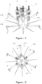
- FIG. 1 The perspective view of the invention subject valve sparing aortic root replacement device is illustrated in Figure - 1.
- FIG. 2 The top view of the invention subject valve sparing aortic root replacement device is illustrated in Figure - 2.
- FIG. 5 The perspective view of the commissure holders on the invention subject valve sparing aortic root replacement device is illustrated in Figure - 5.
- FIG. 7 The perspective view of the window showing the graft diameter scale on the invention subject valve protective aortic stem replacement device is illustrated in Figure - 7.
- FIG. 13 Another perspective view of the invention subject valve sparing aortic root replacement device is illustrated in Figure - 13.
- the main parts constituting the invention subject valve sparing aortic root replacement device are: an adjustable circle (1 ), legs (2), slit surgical tubes (3), cusp caliper (effective height caliper) (4).
- the main parts composing the referred adjustable circle (1 ) are: commissure holders (1 .3) clamped to the commissure (5.1) which is the point where the aortic leaflets (5.2) interconnect, circle screw (1.1) that allows for the referred commissure holders (1 .3) to approach or move away from each other by changing the diameter of the adjustable-diameter circle (1), and window (1.2) that shows the graft diameter scale, the number written on which at the position where the aortic leaflets (5.2) are positioned at the appropriate value is determined as the diameter of the artificial vessel to be chosen.
- the main parts composing the referred legs (2) are: support element (2.1) the convex surface of which sits on the inner surface of the referred adjustable circle (1) and ensures the perpendicular positioning of the legs, leg stabilizer clips (2.2) that fit into the parallel grooves on the legs (2) and ensure fixation, clip stabilizer (2.3) that disables the referred leg stabilizer clips (2.2) and allows the continuous movement of the legs (2), leg springs (2.4) that fulfill the pushing function so as to push the referred adjustable circle (1) from the aortic valve, suture holes (2.5) that ensure the referred legs (2) to stay fixed on the operation suture (3.3) that has been tensed by the slit surgical tubes (3), and the leg connectors (2.6) that allows the vertical movement of the adjustable circle (1) on the legs (2).
- the main parts composing the referred slit surgical tube (3) are: the operation suture (3.3), surgical teflon pledget (3.1) placed as spongy support material preventing the referred operation suture (3.3) from cutting the tissue, the surgical tube stopper that wraps the output end of the referred operation suture (3.3) from the outside and forms support.
- the main parts composing the referred cusp caliper (effective height caliper) (4) are: cusp caliper pins (4.1) that have millimeter scale placed on them, cusp caliper clips (4.2) that fixes the referred cusp caliper pins (4.1), cusp caliper pins (4.1) that perform measurement for each aortic leaflet (5.2) and pin pulling springs (4.3) that fulfill the function of pulling the referred pin endings (4.4).
- the main parts composing the referred aortic annulus (5) are: aortic leaflets (5.2) that connect at the center point and form the aortic valve and commissure (5.1) connected as the binary connection places of the referred aortic valves (5.2).
- the adjustable circle (1) is brought to the maximum width using the circle screw (1.1).
- each leg stabilizer clips (2.2) is placed in the clip stabilizers (2.3) groove that has been made for it by turning clockwise.
- the referred leg springs (2.4) push the adjustable- circle (1) so as to move it away from the aortic valve.
- the strength of the referred leg springs (2.4) is equal to the force by which the surgeon lifts the aortic leaflets (5.2) by pulling with handle forceps and the suture. In other words, they do not have a suspension force that will make any damages in the tissues.
- the referred legs (2) are in continuously movable position. From the 12 operation sutures (3.3) placed as standard, total 10 needles of the 5 critical operation sutures (3.3) that are always fixed and selected for every patient are passed through the suture holes (2.5) on the 5 legs (2) that correspond to them, and are suspended.
- the referred surgical teflon pledget (3.1) is positioned as the spongy support material that prevents the operation suture (3.3) from cutting the tissue.
- the invention subject valve sparing aortic root replacement device is suspended, and moved to the aortic root as guided by the operation suture (3.3).
- the referred slit surgical tubes (3) are placed on the referred 5 operation sutures (3.3).
- the referred slit surgical tubes (3) are moved through the suture holes (2.5) on the referred legs (2) and the surgical tube stopper (3.2) are closed. Under these circumstances, there are 5 slit siners (3) on the 5 measuring legs (2). But, the referred slit surgical tubes (3) have not yet been tightened.
- the referred adjustable circle (1) is slowly contracted and pushed towards the root tissue through the tensing of the operation sutures (3.3) by all slit surgical tubes at the point where the suture holes (2.5) on all legs (2) touch the aortic root tissue.
- the 5 legs (2) are fixed between the slit surgical tubes (3) and the root tissue, at the level of the operation suture (3.3).
- the referred adjustable circle (1) is pushed towards the aortic root and the commissure holders (1.3) are fixed to the aortic leaflet connections called aortic commissure (5.1 ).
- the referred valve sparing aortic root replacement device is slowly released so that it is positioned.
- the aortic commissures rise and remain suspended, and at this point, the movement of the device is limited at the point where the referred commissure holders (1.3) suspend the aortic commissures (5.1).
- leg stabilizer clips (2.2) on each leg (2) are released and it is ensured that each leg (2) is fixed. Now, the aortic valve is suspended with its three-dimensional structure, as it should naturally be.
- the central coaptations of the aortic leaflets (5.2) are ensured by narrowing the adjustable circle (1).
- the height of the aortic leaflet (5.2)(effective height value) is measured over and over again using the cusp caliper (effective height caliper) (4).
- the referred pin pulling springs (4.3) operates by pulling the pin endings (4.4).
- the pin endings (4.4) are positioned at the farthest point to the aortic leaflets (5.2), and resume their starting positions for a new measurement.
- the referred legs (2) are fixed and. thus show the positions of the 5 operation sutures (3.3).
- the referred commissure holders (1.3) are opened and the aortic valve structure is released.
- the referred surgical tube stoppers (3.2) are opened and the slit surgical tubes (3) are taken off the operation sutures (3.3).
- the referred device is detached from the operation sutures (3.3) and moved away from the patient.
- valve sparing aortic root replacement device holds all the measurements.
- the graft taken at the diameter indicated by the valve sparing aortic root replacement device is passed through the legs (2) of the device that are in the hand of the surgeon and attached to the commissure holders (1.3) at the same depth (5mm).
- the suture holes (2.5) on the legs (2) are marked on the graft.
- the places where the 3 aortic commissures (5.1) will be sutured on the graft are defined by marking the bottom points of the commissure holders (1.3).
- the graft is removed from the referred device, the other sutures are placed sequentially in between the points marked on the graft.
- the referred functional aortic annulus (5) has a 3-dimensional structure.
- the referred aortic commissure (5.1) and aortic leaflets (5.2) are structures of the referred functional aortic annulus (5).
- the referred three aortic commissures (5.1) and the three aortic leaflets (5.2) are connected as binary connection.
- the referred functional aortic annulus (5) is fully inserted into the artificial vessel (graft).
- the three commissures (5.1) are suspended in the artificial vessel and sutured. In this way, the three-dimensional structure is reconstructed.
- the referred aortic leaflets (5.2) coapt at the center point and form the aortic valve.
- the referred aortic leaflets (5.2) prevent blood from regurgitating into the heart after the heart has pumped the blood.
- the referred support element (2.1) is tightened by the referred leg connectors (2.6).
- the referred legs (2) move inside the leg connectors (2.6).
- the tightening strength of the support element (2.1) and the leg connector (2.6) allows horizontal movements inside the groove.
- the convex surface of the referred support element (2.1) sits on the inner surface of the adjustable circle (1).
- the concave surface of the leg connector (2.6) sits on the outside of the adjustable circle.
- the tightening of the support element (2.1) and the leg holder (2.6) does not prevent the horizontal movements in the groove.
- the leg connector (2.6) always remains perpendicular and keeps the legs (2) always perpendicular.
Landscapes
- Health & Medical Sciences (AREA)
- Life Sciences & Earth Sciences (AREA)
- Cardiology (AREA)
- Biomedical Technology (AREA)
- Veterinary Medicine (AREA)
- Heart & Thoracic Surgery (AREA)
- Engineering & Computer Science (AREA)
- Animal Behavior & Ethology (AREA)
- General Health & Medical Sciences (AREA)
- Public Health (AREA)
- Surgery (AREA)
- Oral & Maxillofacial Surgery (AREA)
- Transplantation (AREA)
- Vascular Medicine (AREA)
- Molecular Biology (AREA)
- Nuclear Medicine, Radiotherapy & Molecular Imaging (AREA)
- Medical Informatics (AREA)
- Pathology (AREA)
- Prostheses (AREA)
- External Artificial Organs (AREA)
Description
- This invention is related to a novel device that can be used in valve-sparing aortic root replacement surgery, known as the 'David Procedure' (re-implantation technique), which is a special operation for the root of the aorta, the main vessel originating from the heart.
- In heart surgery, the traditional treatment method for aortic valve insufficiency due to aortic root dilatation or dissection is to replace the aorta with an artificial vessel (graft) and to replace the aortic leaflets (which may be structurally normal) with a mechanical aortic valve.
- However, this mechanical valve can never meet the physiological properties of the natural valve. The patient will always be at risk for bleeding, which is one of the most important side effects of life-long anticoagulant medication. The dose of the medication is adjusted on an individual basis, requiring at least a monthly patient visit to hospital.
- In case the medication dose is below the efficacy level, dot formation may occur on the metal valve, which may then rupture and result in embolism (obstruction of an artery).
- The sparing of the patient's own aortic leaflets eliminates the risk of such life-long complications. The David procedure aims to preserve the patient's aortic valve. However, it can only be performed by a limited number of cardiovascular surgeons since it requires advanced experience and technical skills. The device provides the most important parameters for the success of this technique by measuring the necessary data independent of the surgeon and in compliance with the literature.
- One of the most important steps of this operation is the selection of the size (diameter) of the artificial vessel (graft) appropriate for the patient. There are many methods for this selection. Therefore, it is still far from standardization and remains mainly at the discretion of the operating surgeon.
- The sizing of the graft, appropriate in diameter for the patient, is of utmost importance to achieve an optimal coaptation of the aortic leaflets and to avoid postoperative aortic insufficiency. A graft of smaller than optimal size results in prolapse (collapse) with ensuing aortic regurgitation, while selection of a larger graft results in central aortic regurgitation.
- In one of the approaches in the application of David Procedure, the artificial vessel diameter determination techniques to be used as compatible with the patient are defined as follows:
The first step in choosing the right size of the graft is the measurement of the aortic annulus. Several methods have been described for this measurement including: - Measurement of the aortic annulus with preoperative and intraoperative echocardiography (an indirect method)
- Measurement of the aortic annulus with pre-operative computed tomography (an indirect method)
- Measurement with a HEGAR rod (graft diameter is determined by adding 4 mm to the diameter of the appropriately fitting rod)
- Measurement with a mechanical valve sizer (valve sizer is seated around the annulus)
- Measurement with a biological valve sizer (graft diameter is determined by adding 4 mm to the diameter of the sizer which is fully inserted into the aortic annulus)
- Measurement of the commissure height, which Is equal to the diameter of the graft)
- As can be understood from the related literature, there are various methods to measure the aortic annulus. The purpose of the measurement is to determine the diameter of the artificial vessel (graft) to be used. So far, none of these measurement techniques has been shown to be superior to another.
- Differences between these techniques make the selection difficult. It is also difficult to determine which method is better or more accurate. Thus, due to the lack of standardization of these techniques, the choice of an appropriate technique depends largely on the experience, skills, and individual preference of the surgeon.
- Again, it is reported in the literature that, since the determination of the diameter of the artificial vessel to be used for each patient is complex and subjective in these operations. 'the height measured from the three-dimensional structure of the aortic valve (inter-leaflet triangle height) would provide the diameter of the graft to be used.'
- Considering that there is a difference of 2 mm between each graft diameter (26, 28, 30, 32, 34 mm), the lowest points of the leaflets (non-coronary and left coronary leaflets) are manually marked using a marker pen and the base of the triangle is drawn.
- It may be estimated that there may be millimetric differences due to the distribution of the ink in the tissues and that measuring from the lower edge or the top edge of the marking would yield different graft diameter results. This measurement involves determination of the artificial vessel without observing or simulating the positioning of the aortic valve leaflets in relation to each other. As the measurement line is generated manually, it is drawn under eyeball estimate. These individual approaches would give rise to diverse measurement results.
- The Aortic Caliper (Caliper for aortic valve cusps MSS-1 and MSS-2) device measures the height (effective height) of the free edges of the aortic leaflets from their bases. It is stated in the literature that this distance must be 9 mm for surgical success. The caliper only measures this height but for a precise measurement, the surgeon must position this device accurately perpendicular to the ventriculoaortic plane (the plane just below the aortic valves).
- Thus, the positioning of the device is completely surgeon-dependent. It is obvious that, as the positioning is done manually and under eyeball estimate, any deviation in perpendicular positioning will lead to Inaccurate measurement. Objectivity of this measurement has been a matter of debate even at scientific meetings.
- The most important problem encountered in performing the procedure is that aortic regurgitation continues due to the fact that an artificial vessel, the diameter of which has been measured inaccurately, and unable to coapt at the correct configuration. As a consequence, the operation turns out to be a mechanical aortic valve replacement surgery.
- In the current approach, it is attempted to position the aortic valve in the artificial vessel spatially after the artificial vessel is placed at the aortic root and sutured. Incorrect graft selection significantly reduces the success of such positioning.
- Again, in a technique that is used in the literature, the application time is left to individual approach since it is a method that leaves separate measurements and preparation of grafts as compatible with those measurements for each patient to the experience and skill of the surgeon. In that sense, it is not a standardized approach.
- Since the sutures are not aligned on a smooth plane under the three leaflets of the aortic valve, they need to be sutured at different heights on the inner surface of the artificial vessel (graft).
- Errors made at this step cause the inability to suture the valve commissures at the same height in the artificial vessel and as a consequence, the inability of the three leaflets to coapt appropriately. The alignment of the sutures under the aortic valve is unique to the anatomy of each patient.
- Although there are approaches as aimed to determine the points there these sutures correspond to in the artificial vessel, the surgeon has to make the measurements separately for each patient since the values are patient-specific and thus the approach cannot be standardized.
- Each stage of the David procedure necessitates an advanced technical approach. A standardized method is not yet available due to many technical approaches and application difficulties.
- In the European patent document, with document publication number
EP199491381 - The above-mentioned application refers to the device for the fixation and anchoring of aortic valve prosthesis.
- In the literature, the European patent document, with document publication number
EP184837581 - In invention
WO0150985 (A1 - In the referred application, the transvascular implantation of cardiac valve prostheses are performed via catheter systems.
- Due to the mentioned above disadvantages in the aortic valve sparing root replacement procedures, there is a need for an aortic root replacement device used as a new cardiac valve protector.
- The invention relates to a valve sparing aortic root replacement device as defined by
claim 1. - The purpose of the invention is to present a valve protective aortic root replacement device that eliminates the possible disadvantages.
- Another purpose of the invention is to present an approach that allows the surgeon to obtain more reliable and accurate patient data during the David Procedure, which is a difficult procedure technically.
- Another purpose of the invention is to present an approach that does not force the surgeon to choose a method, as it acquires the data on patient basis.
- Another purpose of the invention is to present an approach that prevents the surgeon from not performing the David Procedure.
- Another purpose of the invention is to present an approach that allows the procedure to be performed in larger numbers.
- Another purpose of the invention is to present an approach that reduces the total operation time by reducing the time spent by the surgeon to choose and perform a certain method among a large number of methods.
- Another advantage of the invention is to present an approach that the device can be sterilized and used over and over since it is fully made of metal.
- Another advantage of the invention is to present an approach that eliminates additional costs since it does not require consumables as separate for each patient.
-
- Figure - 1 Perspective view of the invention subject valve protective aortic root replacement device
- Figure - 2 Top view of the invention subject valve protective aortic root replacement device
- Figure - 3 Side view of the invention subject valve protective aortic root replacement device
- Figure - 4 Disassembled view of the invention subject valve protective aortic root replacement device
- Figure - 5 Perspective view of the commissure holders In the invention subject valve protective aortic root replacement device
- Figure - 6 Disassembled view of the commissure holders of the invention subject valve protective aortic root replacement device
- Figure - 7 Perspective view of the window showing the graft diameter scale on the invention subject valve protective aortic root replacement device
- Figure - 8 Disassembled view of the window showing the graft diameter scale on the invention subject valve protective aortic root replacement device
- Figure - 9 Detailed view of the invention subject valve protective aortic root replacement device
- Figure - 10 Detailed view of the invention subject valve protective aortic root replacement device
- Figure - 1 1 Disassembled view of the screw of the adjustable diameter ring on the invention subject valve protective aortic root replacement device
- Figure - 12 Detailed view of the measuring legs on the invention subject valve protective aortic root replacement device
- Figure - 13 Another perspective view of the invention subject valve protective aortic root replacement device
-
- 1. Adjustable circle
- 1.1 Circle Screw
- 1.2 Window showing graft diameter
- 1.3 Commissure holders
- 2. Legs
- 2.1 Support Element
- 2.2 Leg stabilizer clips
- 2.3 Clip stabilizers
- 2.4 Leg springs
- 2.5 Suture holes
- 2.6 Leg connectors
- 3. Slit surgical tubes
- 3.1 Surgecal teflon pledget
- 3.2 Surgecal tube stopper
- 3.3 Operation Suture
- 4. Cusp caliper (effective height caliper)
- 4.1 Cusp caliper pins
- 4.2 Cusp caliper clips
- 4.3 Pin-pulling springs
- 4.4 Pin endings
- 5. Functional Aortic Annulus
- 5.1 Aortic commissure
- 5.2 Aortic Leaflet
- The invention is a valve sparing aortic root replacement device as defined in
Claim 1, used in the operation for valve sparing aortic root replacement. - The invention is the valve sparing aortic root replacement device used in the operation for valve sparing aortic root replacement, which is a special operation aimed for the root of the main aorta exiting from the heart, or known as the 'David Procedure' in the literature, and its feature is characterized by; an adjustable circle (1 ) that determined the graft diameter with the circle screw (1.1) located on it, legs (2) connected to the referred adjustable circle (1) that are clamped on the referred aortic root and allow the placement of the valve sparing aortic root replacement device on the aortic root, slit surgical tube (3) that can hold the operation suture (3.3) that is passed through the aortic root without cutting the needles and prevent the unintended escape of the referred operation suture (3.3) thanks to the spiral slit on it that extends from end to end, surgical tube stopper (3.2) that wraps the output end of the referred operation suture (3.3) from the outside and forms a support, and the cusp caliper (effective height caliper) (4) that is placed on the top edge of the referred adjustable circle (1 ) and ensures the positioning of the pin ending (4.4) on it as perpendicular to the aortic root under all positions, and allows the measurement of the height difference between the lowest and highest levels of the aortic leaflets (5.2) with a totally geometric approach.
- The perspective view of the invention subject valve sparing aortic root replacement device is illustrated in Figure - 1.
- The top view of the invention subject valve sparing aortic root replacement device is illustrated in Figure - 2.
- The side view of the invention subject valve sparing aortic root replacement device is illustrated in Figure - 3.
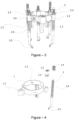
- The disassembled view of the invention subject valve sparing aortic root replacement device is illustrated in Figure - 4.
- The perspective view of the commissure holders on the invention subject valve sparing aortic root replacement device is illustrated in Figure - 5.
- The disassembled view of the commissure holders on the invention subject valve sparing aortic root replacement device is illustrated in Figure - 6.
- The perspective view of the window showing the graft diameter scale on the invention subject valve protective aortic stem replacement device is illustrated in Figure - 7.
- The disassembled view of the window showing the graft diameter scale on the invention subject valve sparing aortic root replacement device is illustrated in Figure -8.
- The detailed view of the invention subject valve sparing aortic root replacement device is illustrated in Figure - 9.
- The detailed view of the invention subject valve sparing aortic root replacement device is illustrated in Figure - 10.
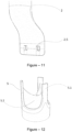
- The detailed view of the screw of the adjustable circle on the invention subject valve sparing aortic root replacement device is illustrated In Figure - 11,
- The detailed view of the legs on the invention subject valve sparing aortic root replacement device is illustrated in Figure - 12.
- Another perspective view of the invention subject valve sparing aortic root replacement device is illustrated in Figure - 13.
- The main parts constituting the invention subject valve sparing aortic root replacement device are: an adjustable circle (1 ), legs (2), slit surgical tubes (3), cusp caliper (effective height caliper) (4).
- The main parts composing the referred adjustable circle (1 ) are: commissure holders (1 .3) clamped to the commissure (5.1) which is the point where the aortic leaflets (5.2) interconnect, circle screw (1.1) that allows for the referred commissure holders (1 .3) to approach or move away from each other by changing the diameter of the adjustable-diameter circle (1), and window (1.2) that shows the graft diameter scale, the number written on which at the position where the aortic leaflets (5.2) are positioned at the appropriate value is determined as the diameter of the artificial vessel to be chosen.
- The main parts composing the referred legs (2) are: support element (2.1) the convex surface of which sits on the inner surface of the referred adjustable circle (1) and ensures the perpendicular positioning of the legs, leg stabilizer clips (2.2) that fit into the parallel grooves on the legs (2) and ensure fixation, clip stabilizer (2.3) that disables the referred leg stabilizer clips (2.2) and allows the continuous movement of the legs (2), leg springs (2.4) that fulfill the pushing function so as to push the referred adjustable circle (1) from the aortic valve, suture holes (2.5) that ensure the referred legs (2) to stay fixed on the operation suture (3.3) that has been tensed by the slit surgical tubes (3), and the leg connectors (2.6) that allows the vertical movement of the adjustable circle (1) on the legs (2).
- The main parts composing the referred slit surgical tube (3) are: the operation suture (3.3), surgical teflon pledget (3.1) placed as spongy support material preventing the referred operation suture (3.3) from cutting the tissue, the surgical tube stopper that wraps the output end of the referred operation suture (3.3) from the outside and forms support.
- The main parts composing the referred cusp caliper (effective height caliper) (4) are: cusp caliper pins (4.1) that have millimeter scale placed on them, cusp caliper clips (4.2) that fixes the referred cusp caliper pins (4.1), cusp caliper pins (4.1) that perform measurement for each aortic leaflet (5.2) and pin pulling springs (4.3) that fulfill the function of pulling the referred pin endings (4.4).
- The main parts composing the referred aortic annulus (5) are: aortic leaflets (5.2) that connect at the center point and form the aortic valve and commissure (5.1) connected as the binary connection places of the referred aortic valves (5.2).
- Before the invention subject valve protective aortic root replacement device is placed on the patient, the adjustable circle (1) is brought to the maximum width using the circle screw (1.1). By pressing on the leg stabilizer clips (2.2) on the referred legs (2), each leg stabilizer clips (2.2) is placed in the clip stabilizers (2.3) groove that has been made for it by turning clockwise. The referred leg springs (2.4) push the adjustable- circle (1) so as to move it away from the aortic valve.
- The strength of the referred leg springs (2.4) is equal to the force by which the surgeon lifts the aortic leaflets (5.2) by pulling with handle forceps and the suture. In other words, they do not have a suspension force that will make any damages in the tissues.
- In this circumstance, the referred legs (2) are in continuously movable position. From the 12 operation sutures (3.3) placed as standard, total 10 needles of the 5 critical operation sutures (3.3) that are always fixed and selected for every patient are passed through the suture holes (2.5) on the 5 legs (2) that correspond to them, and are suspended. The referred surgical teflon pledget (3.1) is positioned as the spongy support material that prevents the operation suture (3.3) from cutting the tissue.
- The invention subject valve sparing aortic root replacement device is suspended, and moved to the aortic root as guided by the operation suture (3.3). The referred slit surgical tubes (3) are placed on the referred 5 operation sutures (3.3).
- The referred slit surgical tubes (3), are moved through the suture holes (2.5) on the referred legs (2) and the surgical tube stopper (3.2) are closed. Under these circumstances, there are 5 slit siners (3) on the 5 measuring legs (2). But, the referred slit surgical tubes (3) have not yet been tightened.
- The referred adjustable circle (1) is slowly contracted and pushed towards the root tissue through the tensing of the operation sutures (3.3) by all slit surgical tubes at the point where the suture holes (2.5) on all legs (2) touch the aortic root tissue. Thus, the 5 legs (2) are fixed between the slit surgical tubes (3) and the root tissue, at the level of the operation suture (3.3).
- The referred adjustable circle (1) is pushed towards the aortic root and the commissure holders (1.3) are fixed to the aortic leaflet connections called aortic commissure (5.1 ).
- The referred valve sparing aortic root replacement device is slowly released so that it is positioned. The aortic commissures rise and remain suspended, and at this point, the movement of the device is limited at the point where the referred commissure holders (1.3) suspend the aortic commissures (5.1).
- Upon the positioning of the referred valve sparing aortic root replacement device, the leg stabilizer clips (2.2) on each leg (2) are released and it is ensured that each leg (2) is fixed. Now, the aortic valve is suspended with its three-dimensional structure, as it should naturally be.
- The central coaptations of the aortic leaflets (5.2) are ensured by narrowing the adjustable circle (1). In this operation that will be made step by step, the height of the aortic leaflet (5.2)(effective height value) is measured over and over again using the cusp caliper (effective height caliper) (4).
- When the cusp caliper pins (4.1) of the referred cusp caliper (effective height caliper) are pressed from above, and the pressure is relieved at the moment the pin endings (4.4) touch the aortic leaflets (5.2), the cusp caliper pins (4.1) are fixed at that position. In addition, when the cusp caliper clips (4.2) are pressed, it is ensured that the legs (2) are returned to their initial positions for a new measurement
- The referred pin pulling springs (4.3) operates by pulling the pin endings (4.4). When the cusp caliper clips (4.2) is pressed, the pin endings (4.4) are positioned at the farthest point to the aortic leaflets (5.2), and resume their starting positions for a new measurement.
- This measurement is made for each aortic leaflet (5.2) using the pin endings (4.4). The values are taken by the millimeter scale on the cusp caliper pins (4.1).
- The process is completed at the moment when this height is 9mm. Now the effective height that is the most important measurement for the success of the David Procedure has been measured with precise accuracy and the appropriate graft (artificial vessel) diameter is displayed on the window showing the graft diameter scale (1.2).
- The referred legs (2) are fixed and. thus show the positions of the 5 operation sutures (3.3). The referred commissure holders (1.3) are opened and the aortic valve structure is released.
- The referred surgical tube stoppers (3.2) are opened and the slit surgical tubes (3) are taken off the operation sutures (3.3). The referred device is detached from the operation sutures (3.3) and moved away from the patient.
- In this condition, the valve sparing aortic root replacement device holds all the measurements. The graft taken at the diameter indicated by the valve sparing aortic root replacement device is passed through the legs (2) of the device that are in the hand of the surgeon and attached to the commissure holders (1.3) at the same depth (5mm).
- Using a surgical marker pen, the suture holes (2.5) on the legs (2) are marked on the graft.
- In addition, the places where the 3 aortic commissures (5.1) will be sutured on the graft are defined by marking the bottom points of the commissure holders (1.3). The graft is removed from the referred device, the other sutures are placed sequentially in between the points marked on the graft.
- The referred functional aortic annulus (5) has a 3-dimensional structure. The referred aortic commissure (5.1) and aortic leaflets (5.2) are structures of the referred functional aortic annulus (5).
- The referred three aortic commissures (5.1) and the three aortic leaflets (5.2) are connected as binary connection.
- As required by the standard operation technique, the referred functional aortic annulus (5) is fully inserted into the artificial vessel (graft). The three commissures (5.1) are suspended in the artificial vessel and sutured. In this way, the three-dimensional structure is reconstructed.
- The referred aortic leaflets (5.2) coapt at the center point and form the aortic valve. The referred aortic leaflets (5.2) prevent blood from regurgitating into the heart after the heart has pumped the blood.
- The referred support element (2.1) is tightened by the referred leg connectors (2.6). The referred legs (2) move inside the leg connectors (2.6). The tightening strength of the support element (2.1) and the leg connector (2.6) allows horizontal movements inside the groove.
- The convex surface of the referred support element (2.1) sits on the inner surface of the adjustable circle (1). The concave surface of the leg connector (2.6) sits on the outside of the adjustable circle. The tightening of the support element (2.1) and the leg holder (2.6) does not prevent the horizontal movements in the groove. However, due to the tight contacts of the 3 curved surfaces with each other, the leg connector (2.6) always remains perpendicular and keeps the legs (2) always perpendicular.
Claims (14)
- A valve sparing aortic root replacement device for use in the operation for valve sparing aortic root replacement, which is a special operation aimed for the root of main aorta originating from the heart, or known as the 'David Procedure' in the literature, characterized by comprising:• an adjustable circle (1) which provides positioning of the measurement legs (2) around the aorta root by means of the adjustable diameter characteristic and which configures the positions of the aortic commissures (5.1) in different diameters and which provides coaptation simulation of aortic leaflets (5.2);• at least one circle screw (1.1) which provides the diameter values of said adjustable circle (1) to be adjusted as desired and positioned on the adjustable circle (1);• at least one measurement leg (2) provided in connection to the adjustable circle (1) and which provides the placement of the valve sparing aortic root replacement device, fixed to the aorta root by means of slit surgical tubes and sutures and which provides alignment of points where the sutures are passed through the graft and which provides preparation of the graft accordingly;• at least one slit surgical tube (3) that secures the legs (2) of the device placed in the operation sutures (3.3) used during the operation and placed in the aortic root guided by these sutures to the aortic root tissue at the level of the operation sutures (3.3);• at least one surgical tube stopper (3.2) that closes the open end of the slit surgical tube (3) and compresses the operation suture (3.3) in tensioned position, in order to provide the operation sutures (3.3) to preserve their tensioned positions in the slit surgical tube (3);• at least one cusp caliper (4) placed on the top edge of said adjustable circle (1) and positioned in an orthogonal manner to the aortic root and which can measure the height difference between the initial edge (the lowest level) and the free edge (the highest level) of each aortic leaflet (5.2) geometrically.
- The valve sparing aortic root replacement device according to claim 1, wherein a window showing graft diameter (1.2), which shows vascular graft diameter scale by means of determining the position where the aortic leaflet (5.2) are positioned at a suitable value, is positioned on the adjustable circle (1).
- The valve sparing aortic root replacement device according to claim 1, wherein at least one commissure holder (1.3), which is attached to the aortic commissure (5.1) which is the point where the aortic leaflets (5.2) interconnect with each other, is provided in the body of the adjustable circle (1).
- The valve sparing aortic root replacement device according to claim 1, wherein a support element (2.1) is provided which is positioned at the inner surface of the adjustable circle (1) and which provides staying of the legs (2) in a perpendicular form and which provides horizontal movement of the legs (2) on the circle.
- The valve sparing aortic root replacement device according to claim 1, wherein at least one leg stabilizer clip (2.2) is provided which is connected to the parallel grooves on the legs (2) and which provides fixation of the legs (2) in the alignment of said parallel grooves.
- The valve sparing aortic root replacement device according to claim 1, wherein at least one clip stabilizer (2.3) that allows continuous movement of the legs (2) by disabling the leg stabilizer clip (2.2).
- The valve sparing aortic root replacement device according to claim 1, wherein at least one leg spring (2.4), which realizes a pushing function in a manner moving the adjustable circle (1) and the commissure holder (1.3) from the aortic valve and which provides resuspension of the aortic commissure (5.1) and which provides positioning of the whole device in the aorta root, is provided at the legs (2).
- The valve sparing aortic root replacement device according to claim 1, wherein it comprises at least one suture hole (2.5), which is located within the legs (2) and which allows the legs (2) to be fixed on the operation suture (3.3) passed therethrough and tensioned.
- The valve sparing aortic root replacement device according to claim 1, wherein at least one leg connector (2.6), which provides movement of the adjustable circle (1) on the legs (2), is provided in the adjustable circle (1).
- The valve sparing aortic root replacement device according to claim 1, wherein it contains at least one surgical teflon pledget (3.1) that prevents the operation suture (3.3) from cutting the tissue and is used as spongy support material.
- The valve sparing aortic root replacement device according to claim 1, wherein at least one cusp caliper pin (4.1) is provided which is connected to the cusp caliper (4) and which provides geometrical measurement of the height difference between initial and free edges of the aortic leaflets (5.2) by means of the millimeter scale existing on said cusp caliper pin (4.1).
- The valve sparing aortic root replacement device according to claim 1, wherein said cusp caliper pins (4.1) include at least one cusp caliper clips (4.2), which ensures that it remains stationary and taken into its initial positions.
- The valve sparing aortic root replacement device according to claim 1, wherein at least one pin ending (4.4), which performs measurement for each aortic leaflet (5.2), is provided in the body of the cusp caliper (4).
- The valve sparing aortic root replacement device according to claim 1, wherein at least one pin-pulling spring (4.3), which performs the function of pulling said pin endings (4.4) to the initial positions, is provided in the body of the cusp caliper pins (4.1).
Applications Claiming Priority (2)
| Application Number | Priority Date | Filing Date | Title |
|---|---|---|---|
| TR2016/18240A TR201618240A2 (en) | 2016-12-09 | 2016-12-09 | MEASUREMENT AND SIMULATION EQUIPMENT USED IN AORTIC LID PROTECTIVE ROOT REPLACEMENT SURGERY |
| PCT/TR2017/050610 WO2019054961A2 (en) | 2016-12-09 | 2017-11-29 | Measurement and simulation device used for aortic valve- sparing root replacement operations |
Publications (4)
| Publication Number | Publication Date |
|---|---|
| EP3551130A2 EP3551130A2 (en) | 2019-10-16 |
| EP3551130A4 EP3551130A4 (en) | 2019-12-11 |
| EP3551130B1 true EP3551130B1 (en) | 2023-11-22 |
| EP3551130C0 EP3551130C0 (en) | 2023-11-22 |
Family
ID=63833624
Family Applications (1)
| Application Number | Title | Priority Date | Filing Date |
|---|---|---|---|
| EP17925444.6A Active EP3551130B1 (en) | 2016-12-09 | 2017-11-29 | Measurement and simulation device used for aortic valve- sparing root replacement operations |
Country Status (4)
| Country | Link |
|---|---|
| US (1) | US11351029B2 (en) |
| EP (1) | EP3551130B1 (en) |
| TR (1) | TR201618240A2 (en) |
| WO (1) | WO2019054961A2 (en) |
Families Citing this family (3)
| Publication number | Priority date | Publication date | Assignee | Title |
|---|---|---|---|---|
| IL298891A (en) | 2020-06-09 | 2023-02-01 | Pfizer | Spiro compounds as melanocortin 4 receptor antagonists and uses thereof |
| WO2023026180A1 (en) | 2021-08-26 | 2023-03-02 | Pfizer Inc. | Amorphous form of (s)-2-(5-((3-ethoxypyridin-2-yl)oxy)pyridin-3-yl)-n-(tetrahydrofuran-3- yl)pyrimidine-5-carboxamide |
| WO2024084360A1 (en) | 2022-10-18 | 2024-04-25 | Pfizer Inc. | Patatin-like phospholipase domain-containing protein 3 (pnpla3) modifiers |
Family Cites Families (16)
| Publication number | Priority date | Publication date | Assignee | Title |
|---|---|---|---|---|
| US5716370A (en) * | 1996-02-23 | 1998-02-10 | Williamson, Iv; Warren | Means for replacing a heart valve in a minimally invasive manner |
| US6494889B1 (en) | 1999-09-01 | 2002-12-17 | Converge Medical, Inc. | Additional sutureless anastomosis embodiments |
| US6598307B2 (en) * | 1999-11-17 | 2003-07-29 | Jack W. Love | Device and method for assessing the geometry of a heart valve |
| WO2001050985A1 (en) | 2000-01-14 | 2001-07-19 | Viacor Incorporated | Tissue annuloplasty band and apparatus and method for fashioning, sizing and implanting the same |
| DE10010074B4 (en) | 2000-02-28 | 2005-04-14 | Fraunhofer-Gesellschaft zur Förderung der angewandten Forschung e.V. | Device for fastening and anchoring heart valve prostheses |
| DE102005003632A1 (en) | 2005-01-20 | 2006-08-17 | Fraunhofer-Gesellschaft zur Förderung der angewandten Forschung e.V. | Catheter for the transvascular implantation of heart valve prostheses |
| US20090299469A1 (en) * | 2008-05-27 | 2009-12-03 | The Board Of Regents Of The University Of Texas System | Cone-shaped aortic root replacement graft and methods for making and using same |
| US8317696B2 (en) * | 2008-12-15 | 2012-11-27 | Coroneo, Inc. | Surgical tool for measurement of valve annulus and cusp geometry |
| US8715207B2 (en) * | 2009-03-19 | 2014-05-06 | Sorin Group Italia S.R.L. | Universal valve annulus sizing device |
| WO2012106354A1 (en) * | 2011-01-31 | 2012-08-09 | St. Jude Medical, Inc. | Adjustable prosthetic anatomical device holder and handle for the implantation of an annuloplasty ring |
| US10182913B2 (en) * | 2012-10-12 | 2019-01-22 | Nikola Dobrilovic | Heart valve sizing ring for valve-sparing aortic root remodeling procedures |
| US9468527B2 (en) * | 2013-06-12 | 2016-10-18 | Edwards Lifesciences Corporation | Cardiac implant with integrated suture fasteners |
| US9622863B2 (en) * | 2013-11-22 | 2017-04-18 | Edwards Lifesciences Corporation | Aortic insufficiency repair device and method |
| US9180005B1 (en) * | 2014-07-17 | 2015-11-10 | Millipede, Inc. | Adjustable endolumenal mitral valve ring |
| US20190015191A1 (en) * | 2017-07-17 | 2019-01-17 | Denis BERDAJS | Prosthetic aortic root replacement graft |
| US11071626B2 (en) * | 2018-03-16 | 2021-07-27 | W. L. Gore & Associates, Inc. | Diametric expansion features for prosthetic valves |
-
2016
- 2016-12-09 TR TR2016/18240A patent/TR201618240A2/en unknown
-
2017
- 2017-11-29 WO PCT/TR2017/050610 patent/WO2019054961A2/en unknown
- 2017-11-29 EP EP17925444.6A patent/EP3551130B1/en active Active
- 2017-11-29 US US16/467,204 patent/US11351029B2/en active Active
Also Published As
| Publication number | Publication date |
|---|---|
| US20200085581A1 (en) | 2020-03-19 |
| WO2019054961A3 (en) | 2019-05-23 |
| US11351029B2 (en) | 2022-06-07 |
| WO2019054961A2 (en) | 2019-03-21 |
| EP3551130C0 (en) | 2023-11-22 |
| EP3551130A4 (en) | 2019-12-11 |
| TR201618240A2 (en) | 2017-01-23 |
| EP3551130A2 (en) | 2019-10-16 |
Similar Documents
| Publication | Publication Date | Title |
|---|---|---|
| AU2004285424B2 (en) | Attachment device and methods of using the same | |
| US9005279B2 (en) | Beating heart buttress and implantation method to prevent prolapse of a heart valve | |
| US9662208B2 (en) | Devices and methods for surgical and percutaneous repair of heart valve lesions | |
| US20040059413A1 (en) | Suture template for facilitating implantation of a prosthetic heart valve | |
| US20060106415A1 (en) | Apparatus to facilitate implantation | |
| US6719785B2 (en) | Aortic heart valve prosthesis implantation tool | |
| EP3551130B1 (en) | Measurement and simulation device used for aortic valve- sparing root replacement operations | |
| WO2008066987A2 (en) | Apparatus, system, and method for delivering an annuloplasty ring | |
| EP0873094A1 (en) | Sizing obturator for prosthetic aortic valves | |
| JP2004510493A (en) | Minimally invasive annuloplasty repair segment delivery template system | |
| WO2000064382A2 (en) | Aortic heart valve prosthesis sizer and marker | |
| KR20210016360A (en) | Removable volume indicator for syringe | |
| KR20240055007A (en) | Intersecting alignment system and alignment method for artificial valves | |
| US20240081995A1 (en) | Self-expandable prosthetic heart valve | |
| CN114948344A (en) | Auxiliary device for valvuloplasty |
Legal Events
| Date | Code | Title | Description |
|---|---|---|---|
| STAA | Information on the status of an ep patent application or granted ep patent |
Free format text: STATUS: THE INTERNATIONAL PUBLICATION HAS BEEN MADE |
|
| PUAI | Public reference made under article 153(3) epc to a published international application that has entered the european phase |
Free format text: ORIGINAL CODE: 0009012 |
|
| STAA | Information on the status of an ep patent application or granted ep patent |
Free format text: STATUS: REQUEST FOR EXAMINATION WAS MADE |
|
| 17P | Request for examination filed |
Effective date: 20190531 |
|
| AK | Designated contracting states |
Kind code of ref document: A2 Designated state(s): AL AT BE BG CH CY CZ DE DK EE ES FI FR GB GR HR HU IE IS IT LI LT LU LV MC MK MT NL NO PL PT RO RS SE SI SK SM TR |
|
| AX | Request for extension of the european patent |
Extension state: BA ME |
|
| A4 | Supplementary search report drawn up and despatched |
Effective date: 20191113 |
|
| RIC1 | Information provided on ipc code assigned before grant |
Ipc: A61B 17/04 20060101ALI20191107BHEP Ipc: A61F 2/24 20060101AFI20191107BHEP Ipc: A61B 17/11 20060101ALI20191107BHEP Ipc: A61F 2/07 20130101ALI20191107BHEP |
|
| DAV | Request for validation of the european patent (deleted) | ||
| DAX | Request for extension of the european patent (deleted) | ||
| STAA | Information on the status of an ep patent application or granted ep patent |
Free format text: STATUS: EXAMINATION IS IN PROGRESS |
|
| 17Q | First examination report despatched |
Effective date: 20220214 |
|
| GRAP | Despatch of communication of intention to grant a patent |
Free format text: ORIGINAL CODE: EPIDOSNIGR1 |
|
| STAA | Information on the status of an ep patent application or granted ep patent |
Free format text: STATUS: GRANT OF PATENT IS INTENDED |
|
| INTG | Intention to grant announced |
Effective date: 20230619 |
|
| GRAS | Grant fee paid |
Free format text: ORIGINAL CODE: EPIDOSNIGR3 |
|
| GRAA | (expected) grant |
Free format text: ORIGINAL CODE: 0009210 |
|
| STAA | Information on the status of an ep patent application or granted ep patent |
Free format text: STATUS: THE PATENT HAS BEEN GRANTED |
|
| AK | Designated contracting states |
Kind code of ref document: B1 Designated state(s): AL AT BE BG CH CY CZ DE DK EE ES FI FR GB GR HR HU IE IS IT LI LT LU LV MC MK MT NL NO PL PT RO RS SE SI SK SM TR |
|
| REG | Reference to a national code |
Ref country code: GB Ref legal event code: FG4D |
|
| REG | Reference to a national code |
Ref country code: CH Ref legal event code: EP |
|
| REG | Reference to a national code |
Ref country code: DE Ref legal event code: R096 Ref document number: 602017076880 Country of ref document: DE |
|
| REG | Reference to a national code |
Ref country code: IE Ref legal event code: FG4D |
|
| U01 | Request for unitary effect filed |
Effective date: 20231219 |
|
| U07 | Unitary effect registered |
Designated state(s): AT BE BG DE DK EE FI FR IT LT LU LV MT NL PT SE SI Effective date: 20240102 |
|
| U20 | Renewal fee paid [unitary effect] |
Year of fee payment: 7 Effective date: 20240125 |
|
| PG25 | Lapsed in a contracting state [announced via postgrant information from national office to epo] |
Ref country code: GR Free format text: LAPSE BECAUSE OF FAILURE TO SUBMIT A TRANSLATION OF THE DESCRIPTION OR TO PAY THE FEE WITHIN THE PRESCRIBED TIME-LIMIT Effective date: 20240223 |
|
| PG25 | Lapsed in a contracting state [announced via postgrant information from national office to epo] |
Ref country code: IS Free format text: LAPSE BECAUSE OF FAILURE TO SUBMIT A TRANSLATION OF THE DESCRIPTION OR TO PAY THE FEE WITHIN THE PRESCRIBED TIME-LIMIT Effective date: 20240322 |
|
| PGFP | Annual fee paid to national office [announced via postgrant information from national office to epo] |
Ref country code: IE Payment date: 20240122 Year of fee payment: 7 |
|
| PG25 | Lapsed in a contracting state [announced via postgrant information from national office to epo] |
Ref country code: ES Free format text: LAPSE BECAUSE OF FAILURE TO SUBMIT A TRANSLATION OF THE DESCRIPTION OR TO PAY THE FEE WITHIN THE PRESCRIBED TIME-LIMIT Effective date: 20231122 |
|
| PG25 | Lapsed in a contracting state [announced via postgrant information from national office to epo] |
Ref country code: IS Free format text: LAPSE BECAUSE OF FAILURE TO SUBMIT A TRANSLATION OF THE DESCRIPTION OR TO PAY THE FEE WITHIN THE PRESCRIBED TIME-LIMIT Effective date: 20240322 Ref country code: GR Free format text: LAPSE BECAUSE OF FAILURE TO SUBMIT A TRANSLATION OF THE DESCRIPTION OR TO PAY THE FEE WITHIN THE PRESCRIBED TIME-LIMIT Effective date: 20240223 Ref country code: ES Free format text: LAPSE BECAUSE OF FAILURE TO SUBMIT A TRANSLATION OF THE DESCRIPTION OR TO PAY THE FEE WITHIN THE PRESCRIBED TIME-LIMIT Effective date: 20231122 |
|
| PGFP | Annual fee paid to national office [announced via postgrant information from national office to epo] |
Ref country code: GB Payment date: 20240112 Year of fee payment: 7 Ref country code: CH Payment date: 20240125 Year of fee payment: 7 |