EP3549111B1 - Performance parameterization of process equipment and systems - Google Patents
Performance parameterization of process equipment and systems Download PDFInfo
- Publication number
- EP3549111B1 EP3549111B1 EP16922874.9A EP16922874A EP3549111B1 EP 3549111 B1 EP3549111 B1 EP 3549111B1 EP 16922874 A EP16922874 A EP 16922874A EP 3549111 B1 EP3549111 B1 EP 3549111B1
- Authority
- EP
- European Patent Office
- Prior art keywords
- performance
- values
- operating parameters
- performance parameter
- parameter
- Prior art date
- Legal status (The legal status is an assumption and is not a legal conclusion. Google has not performed a legal analysis and makes no representation as to the accuracy of the status listed.)
- Active
Links
- 238000000034 method Methods 0.000 title claims description 50
- 230000008569 process Effects 0.000 title description 9
- XLYOFNOQVPJJNP-UHFFFAOYSA-N water Substances O XLYOFNOQVPJJNP-UHFFFAOYSA-N 0.000 claims description 59
- 238000001816 cooling Methods 0.000 claims description 25
- 238000012360 testing method Methods 0.000 claims description 22
- 238000009434 installation Methods 0.000 claims description 12
- 238000004519 manufacturing process Methods 0.000 claims description 12
- 230000004044 response Effects 0.000 claims description 12
- 238000013507 mapping Methods 0.000 claims description 10
- 238000010438 heat treatment Methods 0.000 claims description 8
- 238000005259 measurement Methods 0.000 claims description 8
- 239000003507 refrigerant Substances 0.000 claims description 8
- 238000004891 communication Methods 0.000 claims description 6
- 238000004378 air conditioning Methods 0.000 claims description 5
- 239000013598 vector Substances 0.000 claims description 4
- 238000009423 ventilation Methods 0.000 claims description 3
- 230000005611 electricity Effects 0.000 claims 1
- 230000003542 behavioural effect Effects 0.000 description 13
- 230000006399 behavior Effects 0.000 description 9
- 230000006870 function Effects 0.000 description 8
- 238000013461 design Methods 0.000 description 7
- 239000012530 fluid Substances 0.000 description 7
- 230000001419 dependent effect Effects 0.000 description 5
- 238000012544 monitoring process Methods 0.000 description 5
- 230000008859 change Effects 0.000 description 4
- 230000001143 conditioned effect Effects 0.000 description 4
- 230000000875 corresponding effect Effects 0.000 description 3
- 238000013213 extrapolation Methods 0.000 description 3
- 238000003860 storage Methods 0.000 description 3
- 238000012795 verification Methods 0.000 description 3
- LYCAIKOWRPUZTN-UHFFFAOYSA-N Ethylene glycol Chemical compound OCCO LYCAIKOWRPUZTN-UHFFFAOYSA-N 0.000 description 2
- 230000006978 adaptation Effects 0.000 description 2
- 239000003570 air Substances 0.000 description 2
- 238000004458 analytical method Methods 0.000 description 2
- 238000004364 calculation method Methods 0.000 description 2
- 230000015556 catabolic process Effects 0.000 description 2
- 230000003247 decreasing effect Effects 0.000 description 2
- 238000006731 degradation reaction Methods 0.000 description 2
- 238000001514 detection method Methods 0.000 description 2
- 238000010586 diagram Methods 0.000 description 2
- 238000009826 distribution Methods 0.000 description 2
- 230000000694 effects Effects 0.000 description 2
- 238000005265 energy consumption Methods 0.000 description 2
- 239000000446 fuel Substances 0.000 description 2
- 230000007774 longterm Effects 0.000 description 2
- 238000012423 maintenance Methods 0.000 description 2
- 238000007726 management method Methods 0.000 description 2
- 238000005086 pumping Methods 0.000 description 2
- 230000009471 action Effects 0.000 description 1
- 230000002776 aggregation Effects 0.000 description 1
- 238000004220 aggregation Methods 0.000 description 1
- 238000012550 audit Methods 0.000 description 1
- 230000001276 controlling effect Effects 0.000 description 1
- 230000002596 correlated effect Effects 0.000 description 1
- 230000007423 decrease Effects 0.000 description 1
- 230000007613 environmental effect Effects 0.000 description 1
- 238000001704 evaporation Methods 0.000 description 1
- 230000008020 evaporation Effects 0.000 description 1
- WGCNASOHLSPBMP-UHFFFAOYSA-N hydroxyacetaldehyde Natural products OCC=O WGCNASOHLSPBMP-UHFFFAOYSA-N 0.000 description 1
- 239000007788 liquid Substances 0.000 description 1
- 230000007257 malfunction Effects 0.000 description 1
- 238000013178 mathematical model Methods 0.000 description 1
- 238000010295 mobile communication Methods 0.000 description 1
- 238000012986 modification Methods 0.000 description 1
- 230000004048 modification Effects 0.000 description 1
- 230000003287 optical effect Effects 0.000 description 1
- 238000005457 optimization Methods 0.000 description 1
- 238000009428 plumbing Methods 0.000 description 1
- 230000000246 remedial effect Effects 0.000 description 1
- 239000004065 semiconductor Substances 0.000 description 1
- 239000007787 solid Substances 0.000 description 1
- 230000003068 static effect Effects 0.000 description 1
- 230000001360 synchronised effect Effects 0.000 description 1
- 230000003442 weekly effect Effects 0.000 description 1
Images


Classifications
-
- F—MECHANICAL ENGINEERING; LIGHTING; HEATING; WEAPONS; BLASTING
- F24—HEATING; RANGES; VENTILATING
- F24F—AIR-CONDITIONING; AIR-HUMIDIFICATION; VENTILATION; USE OF AIR CURRENTS FOR SCREENING
- F24F11/00—Control or safety arrangements
- F24F11/30—Control or safety arrangements for purposes related to the operation of the system, e.g. for safety or monitoring
- F24F11/49—Control or safety arrangements for purposes related to the operation of the system, e.g. for safety or monitoring ensuring correct operation, e.g. by trial operation or configuration checks
-
- G—PHYSICS
- G07—CHECKING-DEVICES
- G07C—TIME OR ATTENDANCE REGISTERS; REGISTERING OR INDICATING THE WORKING OF MACHINES; GENERATING RANDOM NUMBERS; VOTING OR LOTTERY APPARATUS; ARRANGEMENTS, SYSTEMS OR APPARATUS FOR CHECKING NOT PROVIDED FOR ELSEWHERE
- G07C3/00—Registering or indicating the condition or the working of machines or other apparatus, other than vehicles
- G07C3/14—Quality control systems
- G07C3/143—Finished product quality control
-
- F—MECHANICAL ENGINEERING; LIGHTING; HEATING; WEAPONS; BLASTING
- F24—HEATING; RANGES; VENTILATING
- F24F—AIR-CONDITIONING; AIR-HUMIDIFICATION; VENTILATION; USE OF AIR CURRENTS FOR SCREENING
- F24F11/00—Control or safety arrangements
- F24F11/30—Control or safety arrangements for purposes related to the operation of the system, e.g. for safety or monitoring
-
- G—PHYSICS
- G07—CHECKING-DEVICES
- G07C—TIME OR ATTENDANCE REGISTERS; REGISTERING OR INDICATING THE WORKING OF MACHINES; GENERATING RANDOM NUMBERS; VOTING OR LOTTERY APPARATUS; ARRANGEMENTS, SYSTEMS OR APPARATUS FOR CHECKING NOT PROVIDED FOR ELSEWHERE
- G07C3/00—Registering or indicating the condition or the working of machines or other apparatus, other than vehicles
- G07C3/08—Registering or indicating the production of the machine either with or without registering working or idle time
Definitions
- Example embodiments generally relate to process equipment and systems, such as Heating Ventilation and Air Conditioning (HVAC) systems.
- HVAC Heating Ventilation and Air Conditioning
- HVAC Building Heating Ventilation and Air Conditioning
- Chilled water plants can comprise of active and passive mechanical equipment which work in concert to reduce the temperature of warm return water before supplying it to the distribution circuit.
- Chilled water plants can have multiple devices and parts, each of which are responsible for certain functions and work together to achieve a common function, such as cooling of a desired space. As some or all of these components can be interrelated, it may be difficult to identify a particular source of any malfunction or depreciation when the plant is in operation.
- United States Patent No. 6,823,680 discloses a data acquisition system and a method including monitoring a cooling system having a refrigerant compressor, evaporator, and condenser, and employs a number of sensors to monitor various operating parameters of the system.
- a database stores predefined operating parameters for a plurality of cooling systems.
- the operating parameters are provided to a computer, which compares the provided operating parameters of the monitored cooling system with the predefined operating parameters to provide diagnostic results for the monitored cooling system.
- Document KR101574590B1 discloses an automated diagnostic system of a fluid supply device for supplying fluid to a semiconductor.
- Document US2009/024239A1 discloses a work management apparatus that analyses and outputs operating conditions of each of a plurality of facilities.
- Performance mapping of equipment performance parameters is accomplished by generating performance maps which outline the expected feature performance parameter behavior of the equipment based on a set of parameters that capture the operating conditions.
- a performance parameter can be defined by an individualized set of parameter coefficients which in turn are dependent on instantaneous operating conditions.
- post installation activities such as continuous commissioning, monitoring and verification, preventative maintenance, fault detection and diagnostics, as well as energy performance or fluid consumption performance benchmarking and long term monitoring can commence to higher degrees of accuracy than current processes; and can accomplish more informative assessments over the life-cycle of the equipment.
- the invention according to claim 1 relates to a method for capturing and mapping equipment performance data for a plurality of devices of a system, the method being performed by at least one controller and comprising: determining, in relation to testing performed on the device, model values of a performance parameter of the device over an operating range of at least two operating parameters which affect the performance parameter, wherein each model value is representative of an operating point of the at least two operating parameters, the testing performed post manufacturing and prior to installation of the device; storing to memory the determined model values of the performance parameter along with a time of said determining and a unique identifier of the device, wherein said model values are stored in the memory as a multi-dimensional performance map; and comparing, when the device is installed in the system, in real-time during normal operation of the system, the detected multi-dimensional performance map of the performance parameter of the device, with respect to the at least two operating parameters, with the stored determined model values of the performance parameter; and in response to said comparing being within a threshold difference, looping the method to the detecting during real-time normal operation
- An example embodiment not set out in the appended claims is a parameterization system for capturing and mapping equipment performance data, the parameterization system including: a device for installation in a system, memory, and at least one controller.
- the at least one controller is configured to: determine, in relation to testing performed on the device, model values of a performance parameter of the device over an operating range of at least two operating parameters which affect the performance parameter, wherein each model value is representative of an operating point of the at least two operating parameters, store to the memory the determined model values of the performance parameter along with a time of said determining, and compare, when the device is installed in the system, detected numerical properties of the device, with respect to the at least two operating parameters, with the stored determined model values of the performance parameter.
- the parameterization system can be used for auditing, surveying, and/or acquiring of parameters of individual devices to be installed in the system.
- At least some example embodiments which do not form part of the claimed invention generally relate to systems that comprise of mechanical equipment that may or may not require electrical power to operate.
- active mechanical equipment can describe mechanical equipment that requires electrical power to operate.
- passive mechanical equipment can describe mechanical equipment that requires no electrical power to operate.
- At least some example embodiments which do not form part of the claimed invention relate to processes, process equipment and systems in the industrial sense, meaning a process that outputs product(s) (e.g. hot water, air) using inputs (e.g. cold water, fuel, air, etc.).
- product(s) e.g. hot water, air
- inputs e.g. cold water, fuel, air, etc.
- An example embodiment which does not form part of the claimed invention is a method for capturing and mapping equipment performance data of a device for installation in a system, the method including: determining, in relation to testing performed on the device, model values of a performance parameter of the device over an operating range of at least two operating parameters which affect the performance parameter, wherein each model value is representative of an operating point of the at least two operating parameters; storing to memory the determined model values of the performance parameter along with a time of said determining; and comparing, when the device is installed in the system, detected numerical properties of the performance parameter of the device, with respect to the at least two operating parameters, with the stored determined model values of the performance parameter.
- a parameterization system for capturing and mapping equipment performance data including: a device for installation in a system, memory, and at least one controller.
- the at least one controller is configured to: determine, in relation to testing performed on the device, model values of a performance parameter of the device over an operating range of at least two operating parameters which affect the performance parameter, wherein each model value is representative of an operating point of the at least two operating parameters, store to the memory the determined model values of the performance parameter along with a time of said determining, and compare, when the device is installed in the system, detected numerical properties of the device, with respect to the at least two operating parameters, with the stored determined model values of the performance parameter.
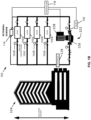
- FIG 1A illustrates one such configuration of a HVAC system such as a chilled water plant 100, in accordance with an example embodiment.
- the chilled water plant 100 can include, for example: one chilled water pump 102, one chiller 120, one condenser water pump 122, and two cooling towers 124.
- more or less numbers of device can exist within each equipment category.
- Other types of equipment and rotary devices may be included in the chilled water plant 100, in some example embodiments.
- the illustrated system can be used to source a building 104 (as shown), campus (multiple buildings), vehicle, plant, generator, heat exchanger, or other suitable infrastructure or load.
- Each control pump 102 may include one or more respective pump devices 106 and a control device 108 for controlling operation of each pump device 106.
- the particular circulating medium may vary depending on the particular application, and may for example include glycol, water, air, fuel, and the like.
- the chiller 120 can include at least a condenser and an evaporator, for example, as understood in the art.
- Each cooling tower 124 can be dimensioned and configured to provide cooling by way of evaporation, and can include a respective fan, for example.
- Each cooling tower 124 can include one or more cells, in an example embodiment.
- the chilled water plant 100 can be configured to provide air conditioning units of the building 104 with cold water to reduce the temperature of the air that leaves the conditioned space before it is recycled back into the conditioned space.
- the chilled water plant 100 can comprise of active and passive mechanical equipment which work in concert to reduce the temperature of warm return water before supplying it to the distribution circuit.
- the chilled water plant 100 may include an interface 118 in thermal communication with a secondary circulating system, for example via the chiller 120 ( Figure 1A ).
- the chilled water plant 100 may include one or more loads 110a, 110b, 110c, 110d, wherein each load may be a varying usage requirement based on air conditioner requirements, HVAC, plumbing, etc.
- Each 2-way valve 112a, 112b, 112c, 112d may be used to manage the flow rate to each respective load 110a, 110b, 110c, 110d.
- the control device 108 responds to this change by increasing the pump speed of the pump device 106 to maintain or achieve the pressure setpoint.
- an applicable load can represent cooling coils to be sourced by the chiller 120, each with associated valves, for example.
- each control pump 102 can be controlled to, for example, achieve a pressure setpoint at the combined output properties represented or detected by external sensor 114, shown at a load point of the building 104.
- the external sensor 114 represents or detects the aggregate or total of the individual output properties of all of the control pumps 102 at the load, in this case, flow and pressure.
- Information on flow and pressure local to the control pump 102 can also be represented or detected by a respective sensor 130, in an example embodiment. Other example operating parameters are described in greater detail herein.
- One or more controllers 116 may be used to co-ordinate the output flow of some or all of the devices of the chilled water plant 100.
- the one or more controllers 116 can include a main centralized controller in some example embodiments, and/or can have some of the functions distributed to one or more of the devices in the overall system of the chilled water plant 100 in some example embodiments.
- the controllers 116 are implemented by a processor which executes instructions stored in memory.
- the controllers 116 are configured to control or be in communication with the loads (110a, 110b, 110c, 110d) and/or valves (112a, 112b, 112c, 112d).
- architectures for equipment modeling by performance parameter tracking can be deployed on data logging structures, or control management systems implemented by a controller or processor executing instructions stored in a non-transitory computer readable medium. Previously stored equipment performance parameters stored by the computer readable medium can be compared and contrasted to real-time performance parameter values.
- a performance parameter of each device performance is modeled by way of model values.
- the model values are discrete values that can be stored in a table, map, database, tuple, vector or multi-parameter computer variables.
- the model values are values of the performance parameter (e.g. the standard unit of measurement for that particular performance parameter, such as in Imperial or SI metric).
- the model values are coefficients for the performance parameter.
- the equipment coefficients are used to prescribe the behavioral responses of the individual units within each equipment group category.
- Each individual unit within each equipment category can individually be modeled by ascribing each coefficient corresponding to a specific set of operating conditions that transcribe the behavioral parameter in question.
- the equipment coefficients can be used for direct comparison or as part of one or more equations to model the behavioral parameter. It can be appreciated that individual units can have varied individual behavior parameters, and can be individually modeled and monitored in accordance with example embodiments.
- Mathematical models prescribing mechanical equipment efficiency performance have constants and coefficients which parameterize the equations. Specifying these coefficients at the time of manufacturing, and tracking their ability to accurately predict real-time performance through the life-cycle of the mechanical item allows for preventative maintenance, fault detection, installation and commissioning verification, as well as energy performance or fluid consumption performance benchmarking and long term monitoring.
- control schemes dependent on coefficient based plant modeling architectures can be configured to optimize energy consumption or fluid consumption of individual equipment, or the system as a whole, and monitored over the life-cycle of equipment comprising the central cooling plant. These energy control coefficients can subsequently be adjusted as building, plant, and outdoor environment conditions change over time.
- each pump 102, 122 and fan of the cooling tower 124 behavioral parameters are modeled as functions of one of several of their corresponding operating parameters (conditions) relative to their design operating parameters (conditions), raised to the power of an ascribed coefficient.
- the coefficients can be stored as multi-parameter computer variables. In an example embodiment, the coefficients can be stored as one or more N-dimensional tables or maps. In an example embodiment, the coefficients can be stored as one or more databases, or as vectors or tuples.
- performance maps can be constructed for each equipment group category, and each unit within each equipment group.
- multi-dimensional performance maps can delineate a desired behavioral parameter given a specific set of operating conditions.
- the span of all possible operating conditions defines the boundaries of the multi-dimensional performance map.
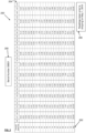
- Figure 2 illustrates an example two-dimensional performance map 200 modeling the cooling tower 124 fitted with a 10 HP fan motor.
- Figure 2 also illustrates a timestamp 206 which shows the time of testing, a serial number 208 which are stored in memory along with the map.
- power draw kW
- Fan Speed and Outdoor Temperature function as the bounding operating parameters.
- the two dimensional Cooling Tower performance map 200 in Figure 2 illustrates the Power Consumption behavioral parameter being mapped by, for example, two of several possible operating parameters (conditions): Speed Percentage of the Fan Motor 202, and Ambient Temperature 204 (in Fahrenheit).
- PARAM_DD would correspond with the operating conditions that the cooling tower 124 was designed to operate by the designer. Values in the table cells would be considered Param_xperf.
- At least one of the operating parameters comprises: contact air-water area per cooling tower active volume, relative cooling tower volume, entering water temperature, leaving water temperature, wet bulb temperature, power consumed, fluid loss, water flow, and/or air flow.
- performance maps can be constructed for desirable behavioral parameters for chillers 120 and pumps 102, 122 that tabularize equipment output based on a set of dimensioning operating conditions.
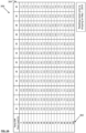
- Figures 3A and 3B illustrate an example two-dimensional performance map 300 modeling a chiller 120 fitted with a 1500 kW rated compressor. Therein, power draw (kW) is the modeled behavioral parameter of choice. Chiller load percentage 302 and temperature difference 304 (in Fahrenheit) function as the bounding operating parameters, in this example.
- At least one of the operating parameters comprises: water flow, refrigerant flow, evaporator entering temperature, evaporator leaving temperature, condenser entering temperature, condenser leaving temperature, refrigerant pressure difference, power consumed, and/or number of active units.
- the number of active units can refer to the number of condenser water pumps 122 which are on ("active") for the pumping station of the chiller 120 of interest. As more pumps 122 become active, the total power consumption of the pumping station also increases. This is especially true if the pumps being activated consecutively are specified to operate at the same RPM (speed), as is standard practice.
- the manner in which the system sequentially "stage-on” and “stage-off” pumps can have an effect on the energy consumed over a period of time.
- the described mapping of equipment performance processes can allow a supervisory optimization module which references these performance maps, to evaluate and optimize controller automation for example.
- the number of active units can refer to other types of pumps 102 or active devices, as applicable, in other example embodiments.
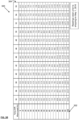
- Figures 4A and 4B illustrate an example two-dimensional performance map 400 modeling a pump 102 fitted with a 230 HP motor. Therein, power draw (kW) is the modeled behavioral parameter of choice. Flow Rate (design flow percentage 402) and Impeller Speed (impeller speed percentage 404) function as the bounding operating parameters.
- a pump 102 may be selected to provide 100% flow at 100% speed (for example, that is how pumps can be selected for an application), with a corresponding power consumption of 174 kW (the PARAM_DD).
- the PARAM_DD the power consumption of 174 kW
- the PARAM_xperf the power consumed is described as PARAM_xperf
- the Design Day conditions are a subset of all possible operating conditions.
- the map 400 includes "N/A" values (null values) which represent operating parameters that would never occur or would not be likely to occur.
- At least one of the operating parameters comprises: water flow, impeller speed, pump head pressure, pump shaft power draw, number of active units, vibration in x, y, and z plane, and/or noise sound level.
- vibration can be quantified using at least one of amplitude and frequency, in some example embodiments.
- n-dimensional operating parameters may be used to characterize a featured performance parameter of the mechanical item while operating. Given a set of n-parameter coordinates, the map demarcates the expected utilization of the featured performance parameter for the piece of equipment.
- the performance maps can be generated at the time of factory testing prior to shipment, post manufacturing. Performance of each device is compared to the maps in real-time, subsequent to installation. In this way, diagnostics, monitoring, and performance verification processes can easily detect degradation in performance for the device, and trigger remedial responses from local or remote operations managers before catastrophic failures can occur, or wasted energy consumption can accrue.
- Figure 5 illustrates a flow diagram of a method 500 for capturing, mapping, and/or structuralizing equipment performance data of a device for installation in a system, in accordance with an example embodiment.
- the device can be each individual device installed in the chilled water plant 100 ( Figure 1A ).
- models values of a performance parameter for each device can be initially determined post manufacturing, and prior to shipment, which individually parameterizes that specific piece of equipment's behavior and performance. This can be conceptually thought of as taking a snapshot of the specific performance of that particular device at a specified point in time.
- the parameterization enables modeling, predictive performance, and other operating observations.
- the instantaneous snapshot can be juxtaposed with the original factory tested snapshot recorded at the time of shipment for diagnostics purposes. Further snapshots can be taken over the lifetime of the particular device, so that comparisons can be made with one or more earlier snapshots.
- each individual piece of equipment will have its own individual set of performance parameters, and efficiency coefficients similar to a snapshot taken at a specific point in time. These parameters and/or coefficients can be measured over different times to see what changes have occurred over time.
- the equipment model values is the collective aggregation of several behavior and performance assessment tools which characterize the manner in which, and execution of, mechanical equipment performs the tasks that they were designed to accomplish.
- these model values can include at least one or both of the following features: equipment efficiency coefficients and equipment performance maps.
- the method 500 is for capturing, mapping and parameterizing performance of each individual device which are to be installed in a system such as the chilled water plant 100 or other HVAC system.
- the devices for the system such as the pumps 102, 122, the chiller 120, and the cooling towers 124 ( Figure 1A ), are manufactured. It can be appreciated that, in some example embodiments, these devices may be manufactured at different manufacturing facilities, and at different times.
- a testing facility may be at the manufacturing facility, offsite, or at the installation site in some example embodiments.
- Some aspects of the method 500 can be performed by one or more controllers, where applicable.
- a central controller 116 is used to perform aspects of the method.
- multiple controllers and/or multiple parties are used to perform the method.
- each device is tested to determine the model values, e.g. coefficients or values in a standard measurement unit.
- each device can be tested in a testing facility, wherein the instant operating parameters can be controlled to be at a specific operating point, and then varied over a range for each operating parameter at other specific operating points.
- the values of a performance parameter such as energy consumed are illustrated in the maps 200, 300, 400 shown in Figures 2 , 3A and 3B , and 4A and 4B , respectively.
- maps for the coefficients can be stored for use with Equations 1 and 2, above.
- event 504 includes testing for the model values (e.g.
- testing can include varying the operating parameters over the range at different specific operating points.
- testing can include maintaining some operating parameters constant while varying one or more of the other operating parameters to result in different operating points, and then performing similar testing by varying the next operating parameter of interest.
- the model values can be determined by storing the values in standard units for each operating point or by calculating a coefficient from each of these tested values. The model values may therefore be stored as discrete values, in association with each operating point.
- Each model value is representative of an operating point of the at least two operating parameters. It can be appreciated that, in an example embodiment, more than two operating parameters can be mapped in an N-dimensional map, a database, vector, tuple or a multi-parameter computer variable.
- the coefficients may be determined by back-calculating using Equation 1, for example.
- the coefficients may be determined by inferring when there are multiple coefficients such as in the case of Equation 2. In such a case of multi-coefficient equations, inferring can use many Xperf values as coefficients to back-calculate (e.g. at least 2 equations for 2 unknowns).
- the back-calculated ⁇ A,B ⁇ coefficients can be inferred to cover a region of the performance map; rather than a single elemental map array entry. This provides a tradeoff of accuracy for gains on implementation simplicity and required RAM/ROM resources needed for realization.
- the method 500 includes storing in memory the model values of the performance parameter, which can be at least one or both of the determined coefficients or the determined values of the performance parameter.
- this data can be initially stored in one memory such as at the original production facility, and such data is sent and stored to another memory, accessible by the controller 116 of the overall chilled water plant 100 or the overall system.
- a time of testing is also stored to the memory in associate with the particular device.
- the stored time can be the actual time and/or date of testing, and/or can be a general statement such as "tested prior to shipping". See, for example, timestamp 206 which shows the date and general statement, and which is stored with the map 200 in Figure 2 .
- a unique device identifier for the device such as a serial number 208 or alphanumeric identifier, can be stored in the memory in association with the coefficients/values of the performance parameter. Therefore, for example, each individual device of the same time can be modeled with its own coefficients or values of the performance parameter.
- the devices are shipped to the destination such as the location of the building 104 ( Figure 1A ) where the devices are to be installed.
- the devices are installed in the chilled water plant 100.
- the chilled water plant 100 then operates as normal with the devices in operation. Operation of one device in the system will affect operation of the other devices. Similarly, operation of one type of device in the system will affect operation of other types of devices.
- the chilled water plant 100 will be subject to a range of N-dimensional operating parameters.
- the method 500 at event 512 includes detecting, for each device, numerical properties of the performance parameter at the N-dimensional operating parameters. Detecting the numerical properties can include direct measurement or calculating/inferring, as applicable. This allows the coefficients or values of the performance parameter to be measured or calculated. The coefficients can be back-calculated or inferred in real time from measured values of the performance parameter, for example.
- Sensors can be used for measuring the applicable information and for providing data in response to the measured information.
- Data from the sensors can be values in a standard measurement unit, in an example embodiment.
- Some example sensors 114, 130 are illustrated in Figure 1B , for example. This allows the controller 116 to model, monitor, audit, survey, acquire, and/or detect the operating parameters and the performance parameters in real-time, and so the controller 116 can provide applicable responses in real-time.
- the determined numerical properties can also be stored in memory as model parameters.
- these more recent model parameters can be stored as maps, along with a time of acquisition, and the unique identifier of that device.
- the method 500 includes comparing the detected numerical properties of the performance parameter of each device with any one, some, or all of the previously stored model values of the performance parameter. In an example embodiment, this can include accessing the previously stored data from the memory, which was received or generated at event 506 and/or event 522.
- the comparison can include calculating a difference such as subtraction or calculation of a ratio or calculation of a percentage difference.
- the detected numerical properties are compared with any of the previously modeled values, for example using a predetermined rule or criteria. If the difference for all of the devices is within a threshold (if "no"), the method loops to event 512 wherein further measurements and comparisons are to be made. If the threshold is exceed for one of the devices (if "yes"), at event 518 an alert or status notification can be outputted to a display screen or sent to another communication device. The details of the alert may be stored to the memory for future logging and analysis. Therefore, it can be determined which particular device has a potential fault, and further action can be taken.
- the particular device can be replaced or repaired in response. If the device is replaced, in an example embodiment, the performance parameters of the new device were previously determined and stored (e.g. event 504) prior to shipping. If the device is repaired, testing can be performed to determine its new performance parameters, similar to event 504. Those new performance parameters can be stored (similar to event 506) and used for comparison purposes at event 514.
- the threshold at event 516 is preselected and may be fixed. In some other example embodiments, the threshold at event 518 can change depending on factors such as reasonable wear and age of the device. In an example embodiment, the threshold is dependent on a time difference between the stored timestamp of the model parameters and a time of the presently detected numerical properties. The threshold may be lower for smaller time differences and higher for larger time differences.
- map-to-map comparison can be made between modeled values taken at different times. For example, one or more performance parameters taken at the same operating parameters can be compared between two different maps taken at two different times.
- determining discrete values for the maps can comprise measuring values for some of the coefficients/values of the performance parameter by operating the device over some but not all of the operating range with respect to the operating parameters. For the remaining values, these can be inferred or calculated using mathematical routines, for example by interpolating or extrapolating at least some of the coefficients or values of the performance parameter based on the measured values. For example, this can be done by straight-line, quadratic, exponential, or by other forms of interpolation/ extrapolation.
- Equations 1 or 2 can be used to assist to interpolate/ extrapolate the remaining missing values of the maps.
- the interpolation! extrapolation can be performed ahead of time, for example during event 504 of Figure 5 .
- the interpolation/ extrapolation can be performed in real time during event 514 of Figure 5 , wherein the missing values are calculated during actual operation of the devices in the system.
- the missing coefficient/value may be calculated in real time to determine a coefficient/value for actual measured operating parameters that might exist between two of the already populated map cells.
- model values as discrete values within the maps, complex multi-parameter values can be readily stored and accessed for real-time comparison during operation.
- N/A null variable
- Model values of the performance parameter for these operating parameters do not need to be tested, saving time and resources. If these conditions do occur, in an example embodiment, the applicable model values can be extrapolated as needed.
- this can include storing to memory, during operation of the system, the determined numerical properties of the performance parameter along with the respective measured operating parameters (for example as maps) and the unique identifier of the device.
- This storing at event 522 can be performed at different points in time, such as periodically, daily, weekly, monthly, annually etc. Accordingly, an ongoing log of the lifetime of the device can be generated, to see trends and to determine when a fault had occurred. For example, normal wear-and-tear or degradation can be expected for some devices, while drastic changes can result in an alert being outputted.
- this information can be used for applications such as to optimize and control of the collective devices in the chilled water plant 100.
- a consumable variable such as energy consumed or fluid consumed can be optimized in a model for the system as a whole.
- These energy control coefficients/values can subsequently be adjusted for the model over time, for example as the individual devices degrade or become damaged or if environmental conditions or a design day changes.
- a model can be used and updated for the device, for example using one or more methods or systems described in Applicant's PCT Patent Application No. PCT/CA2013/050868 , published as WO 2014/089694 .
- the device of interest in the system can include a passive mechanical equipment.
- Example operating parameters for this include: fluid flow through the device (e.g. air or water), pressure differential across the device, ambient or device temperature, energy lost through the device, etc.
- the system shown in Figure 1B can represent a heating circulating system ("heating plant"), with suitable adaptation.
- the heater plant may include an interface 118 in thermal communication with a secondary circulating system.
- control valves manage the flow rate to heating elements (e.g., loads).
- the control devices 108 can respond to changes in the heating elements by increasing or decreasing the pump speed of the pump device 106 to achieve the specified output setpoint.
- the pump device 106 may take on various forms of pumps which have variable speed control.
- the pump device 106 includes at least a sealed casing which houses the pump device 106, which at least defines an input element for receiving a circulating medium and an output element for outputting the circulating medium.
- the pump device 106 includes one or more operable elements, including a variable motor which can be variably controlled from the control device 108 to rotate at variable speeds.
- the pump device 106 also includes an impeller which is operably coupled to the motor and spins based on the speed of the motor, to circulate the circulating medium.
- the pump device 106 may further include additional suitable operable elements or features, depending on the type of pump device 106. Some device properties of the pump device 106, such as the motor speed and power, may be self-detected by the control device 108.
- the control device 108 for each control pump 102 may include an internal detector or sensor, typically referred to in the art as a "sensorless" control pump because an external sensor is not required.
- the internal detector may be configured to self-detect, for example, device properties such as the power and speed of the pump device 106. Other input variables may be detected.
- the pump speed of the pump device 106 may be varied to achieve a pressure and flow setpoint of the pump device 106 in dependence of the internal detector.
- a program map may be used by the control device 108 to map a detected power and speed to resultant output properties, such as head output and flow output.
- the relationship between parameters may be approximated by particular affinity laws, which may be affected by volume, pressure, and Brake Horsepower (BHP).
- affinity laws which may be affected by volume, pressure, and Brake Horsepower (BHP).
- BHP Brake Horsepower
- D1/D2 Q1/Q2
- H1/H2 D1 2 /D2 2
- Variations may be made in example embodiments of the present disclosure. Some example embodiments may be applied to any variable speed device, and not limited to variable speed control pumps. For example, some additional embodiments may use different parameters or variables, and may use more than two parameters (e.g. three parameters on a three dimensional map, or N parameters on a N-dimensional map). Some example embodiments may be applied to any devices which are dependent on two or more correlated parameters. Some example embodiments can include variables dependent on parameters or variables such as liquid, temperature, viscosity, suction pressure, site elevation and number of devices or pump operating.
- each illustrated block or module may represent software, hardware, or a combination of hardware and software. Further, some of the blocks or modules may be combined in other example embodiments, and more or less blocks or modules may be present in other example embodiments. Furthermore, some of the blocks or modules may be separated into a number of sub-blocks or sub-modules in other embodiments.
- present embodiments are also directed to various apparatus such as a server apparatus including components for performing at least some of the aspects and features of the described methods, be it by way of hardware components, software or any combination of the two, or in any other manner.
- apparatus such as a server apparatus including components for performing at least some of the aspects and features of the described methods, be it by way of hardware components, software or any combination of the two, or in any other manner.
- an article of manufacture for use with the apparatus such as a pre-recorded storage device or other similar non-transitory computer readable medium including program instructions recorded thereon, or a computer data signal carrying computer readable program instructions may direct an apparatus to facilitate the practice of the described methods. It is understood that such apparatus, articles of manufacture, and computer data signals also come within the scope of the present example embodiments.
- the one or more controllers can be implemented by or executed by, for example, one or more of the following systems: Personal Computer (PC), Programmable Logic Controller (PLC), Microprocessor, Internet, Cloud Computing, Mainframe (local or remote), mobile phone or mobile communication device.
- PC Personal Computer
- PLC Programmable Logic Controller
- Microprocessor Internet
- Cloud Computing Cloud Computing
- Mainframe Local or remote
- computer readable medium includes any medium which can store instructions, program steps, or the like, for use by or execution by a computer or other computing device including, but not limited to: magnetic media, such as a diskette, a disk drive, a magnetic drum, a magneto-optical disk, a magnetic tape, a magnetic core memory, or the like; electronic storage, such as a random access memory (RAM) of any type including static RAM, dynamic RAM, synchronous dynamic RAM (SDRAM), a read-only memory (ROM), a programmable-read-only memory of any type including PROM, EPROM, EEPROM, FLASH, EAROM, a so-called "solid state disk", other electronic storage of any type including a charge-coupled device (CCD), or magnetic bubble memory, a portable electronic data-carrying card of any type including COMPACT FLASH, SECURE DIGITAL (SD-CARD), MEMORY STICK, and the like; and optical media such as a Compact Disc (CD), Digital Versatile Disc (CD), Digital Versatile
Description
- Example embodiments generally relate to process equipment and systems, such as Heating Ventilation and Air Conditioning (HVAC) systems.
- Building Heating Ventilation and Air Conditioning (HVAC) systems can contain central chilled water plants that are designed to provide air conditioning units with cold water as to reduce the temperature of the air that leaves the conditioned space before it is recycled back into the conditioned space.
- Chilled water plants can comprise of active and passive mechanical equipment which work in concert to reduce the temperature of warm return water before supplying it to the distribution circuit.
- Chilled water plants can have multiple devices and parts, each of which are responsible for certain functions and work together to achieve a common function, such as cooling of a desired space. As some or all of these components can be interrelated, it may be difficult to identify a particular source of any malfunction or depreciation when the plant is in operation.
- Other difficulties with existing systems may be appreciated in view of the Detailed Description of Example Embodiments, herein below.
United States Patent No. 6,823,680 discloses a data acquisition system and a method including monitoring a cooling system having a refrigerant compressor, evaporator, and condenser, and employs a number of sensors to monitor various operating parameters of the system. A database stores predefined operating parameters for a plurality of cooling systems. The operating parameters are provided to a computer, which compares the provided operating parameters of the monitored cooling system with the predefined operating parameters to provide diagnostic results for the monitored cooling system. DocumentKR101574590B1 US2009/024239A1 discloses a work management apparatus that analyses and outputs operating conditions of each of a plurality of facilities. - Particular aspects of the invention are set out in the appended claims. Performance mapping of equipment performance parameters is accomplished by generating performance maps which outline the expected feature performance parameter behavior of the equipment based on a set of parameters that capture the operating conditions. A performance parameter can be defined by an individualized set of parameter coefficients which in turn are dependent on instantaneous operating conditions.
- With the performance maps set following the manufacturing process, and prior to shipment, post installation activities such as continuous commissioning, monitoring and verification, preventative maintenance, fault detection and diagnostics, as well as energy performance or fluid consumption performance benchmarking and long term monitoring can commence to higher degrees of accuracy than current processes; and can accomplish more informative assessments over the life-cycle of the equipment.
- The invention according to claim 1 relates to a method for capturing and mapping equipment performance data for a plurality of devices of a system, the method being performed by at least one controller and comprising: determining, in relation to testing performed on the device, model values of a performance parameter of the device over an operating range of at least two operating parameters which affect the performance parameter, wherein each model value is representative of an operating point of the at least two operating parameters, the testing performed post manufacturing and prior to installation of the device; storing to memory the determined model values of the performance parameter along with a time of said determining and a unique identifier of the device, wherein said model values are stored in the memory as a multi-dimensional performance map; and comparing, when the device is installed in the system, in real-time during normal operation of the system, the detected multi-dimensional performance map of the performance parameter of the device, with respect to the at least two operating parameters, with the stored determined model values of the performance parameter; and in response to said comparing being within a threshold difference, looping the method to the detecting during real-time normal operation of the system; in response to said comparing exceeding the threshold difference, outputting an alert or sending the alert to a communication device; wherein each device is a pump or a chiller of a chilled water plant and the operational parameter for the pump comprise at least one or all of: water flow, impeller speed, pump head pressure, pump shaft power draw, number of active units, vibration, and/or noise sound level and the operating parameter for the chiller comprises at least one of water flow, refrigerant flow, evaporator entering temperature, evaporator leaving temperature, condenser entering temperature, condenser leaving temperature, refrigerant pressure difference, power consumed, and/or number of active units, wherein the performance parameter comprises power consumed by the pump or power consumed by the chiller of the chilled water plant. Moreover, the invention relates to a chilled water plant according to claim 18.
- An example embodiment not set out in the appended claims is a parameterization system for capturing and mapping equipment performance data, the parameterization system including: a device for installation in a system, memory, and at least one controller. The at least one controller is configured to: determine, in relation to testing performed on the device, model values of a performance parameter of the device over an operating range of at least two operating parameters which affect the performance parameter, wherein each model value is representative of an operating point of the at least two operating parameters, store to the memory the determined model values of the performance parameter along with a time of said determining, and compare, when the device is installed in the system, detected numerical properties of the device, with respect to the at least two operating parameters, with the stored determined model values of the performance parameter.
- The parameterization system can be used for auditing, surveying, and/or acquiring of parameters of individual devices to be installed in the system.
- Reference will now be made, by way of example, to the accompanying drawings which show example embodiments of the present application, and in which:
-
Figure 1A illustrates a graphical representation of a chilled water plant providing cold water to a building, to which example embodiments may be applied. -
Figure 1B illustrates another graphical representation of aspects of the chilled water plant shown inFigure 1A . -
Figure 2 illustrates an example two-dimensional performance map modeling a cooling tower fitted with a 10 HP fan motor, in accordance with an example embodiment. -
Figures 3A and3B illustrate an example two-dimensional performance map modeling a chiller fitted with a 1500 kW rated compressor, in accordance with an example embodiment. -
Figures 4A and4B illustrate an example two-dimensional performance map modeling a pump fitted with a 230 HP motor, in accordance with an example embodiment. -
Figure 5 illustrates a flow diagram of a method for capturing, mapping, and/or structuralizing equipment performance data of a device for installation in a system, in accordance with an example embodiment. - Similar reference numerals may have been used in different figures to denote similar components.
- At least some example embodiments which do not form part of the claimed invention generally relate to systems that comprise of mechanical equipment that may or may not require electrical power to operate. Where applicable as referenced herein, active mechanical equipment can describe mechanical equipment that requires electrical power to operate. Similarly, passive mechanical equipment can describe mechanical equipment that requires no electrical power to operate.
- At least some example embodiments which do not form part of the claimed invention relate to processes, process equipment and systems in the industrial sense, meaning a process that outputs product(s) (e.g. hot water, air) using inputs (e.g. cold water, fuel, air, etc.).
- An example embodiment which does not form part of the claimed invention is a method for capturing and mapping equipment performance data of a device for installation in a system, the method including: determining, in relation to testing performed on the device, model values of a performance parameter of the device over an operating range of at least two operating parameters which affect the performance parameter, wherein each model value is representative of an operating point of the at least two operating parameters; storing to memory the determined model values of the performance parameter along with a time of said determining; and comparing, when the device is installed in the system, detected numerical properties of the performance parameter of the device, with respect to the at least two operating parameters, with the stored determined model values of the performance parameter.
- Another example embodiment which does not form part of the claimed invention is a parameterization system for capturing and mapping equipment performance data, including: a device for installation in a system, memory, and at least one controller. The at least one controller is configured to: determine, in relation to testing performed on the device, model values of a performance parameter of the device over an operating range of at least two operating parameters which affect the performance parameter, wherein each model value is representative of an operating point of the at least two operating parameters, store to the memory the determined model values of the performance parameter along with a time of said determining, and compare, when the device is installed in the system, detected numerical properties of the device, with respect to the at least two operating parameters, with the stored determined model values of the performance parameter.
-
Figure 1A illustrates one such configuration of a HVAC system such as a chilledwater plant 100, in accordance with an example embodiment. As shown inFigure 1A , the chilledwater plant 100 can include, for example: one chilledwater pump 102, onechiller 120, onecondenser water pump 122, and twocooling towers 124. In an example embodiment, more or less numbers of device can exist within each equipment category. Other types of equipment and rotary devices may be included in the chilledwater plant 100, in some example embodiments. - The illustrated system can be used to source a building 104 (as shown), campus (multiple buildings), vehicle, plant, generator, heat exchanger, or other suitable infrastructure or load. Each
control pump 102 may include one or morerespective pump devices 106 and acontrol device 108 for controlling operation of eachpump device 106. The particular circulating medium may vary depending on the particular application, and may for example include glycol, water, air, fuel, and the like. Thechiller 120 can include at least a condenser and an evaporator, for example, as understood in the art. Eachcooling tower 124 can be dimensioned and configured to provide cooling by way of evaporation, and can include a respective fan, for example. Eachcooling tower 124 can include one or more cells, in an example embodiment. - The chilled
water plant 100 can be configured to provide air conditioning units of thebuilding 104 with cold water to reduce the temperature of the air that leaves the conditioned space before it is recycled back into the conditioned space. The chilledwater plant 100 can comprise of active and passive mechanical equipment which work in concert to reduce the temperature of warm return water before supplying it to the distribution circuit. - Referring to
Figure 1B , thechilled water plant 100 may include aninterface 118 in thermal communication with a secondary circulating system, for example via the chiller 120 (Figure 1A ). The chilledwater plant 100 may include one ormore loads way valve respective load control device 108 responds to this change by increasing the pump speed of thepump device 106 to maintain or achieve the pressure setpoint. If the differential pressure across the load increases, thecontrol device 108 responds to this change by decreasing the pump speed of thepump device 106 to maintain or achieve the pressure setpoint. In some example embodiments, an applicable load can represent cooling coils to be sourced by thechiller 120, each with associated valves, for example. - Referring still to
Figure 1B , the output properties of eachcontrol pump 102 can be controlled to, for example, achieve a pressure setpoint at the combined output properties represented or detected byexternal sensor 114, shown at a load point of thebuilding 104. Theexternal sensor 114 represents or detects the aggregate or total of the individual output properties of all of thecontrol pumps 102 at the load, in this case, flow and pressure. Information on flow and pressure local to thecontrol pump 102 can also be represented or detected by arespective sensor 130, in an example embodiment. Other example operating parameters are described in greater detail herein. - One or more controllers 116 (e.g. processors) may be used to co-ordinate the output flow of some or all of the devices of the chilled
water plant 100. The one ormore controllers 116 can include a main centralized controller in some example embodiments, and/or can have some of the functions distributed to one or more of the devices in the overall system of the chilledwater plant 100 in some example embodiments. In an example embodiment, thecontrollers 116 are implemented by a processor which executes instructions stored in memory. In an example embodiment, thecontrollers 116 are configured to control or be in communication with the loads (110a, 110b, 110c, 110d) and/or valves (112a, 112b, 112c, 112d). - In an example embodiment, architectures for equipment modeling by performance parameter tracking can be deployed on data logging structures, or control management systems implemented by a controller or processor executing instructions stored in a non-transitory computer readable medium. Previously stored equipment performance parameters stored by the computer readable medium can be compared and contrasted to real-time performance parameter values.
- In some example embodiments, a performance parameter of each device performance is modeled by way of model values. In some example embodiments, the model values are discrete values that can be stored in a table, map, database, tuple, vector or multi-parameter computer variables. In some other example embodiments, the model values are values of the performance parameter (e.g. the standard unit of measurement for that particular performance parameter, such as in Imperial or SI metric).
- In some example embodiments, the model values are coefficients for the performance parameter. The equipment coefficients are used to prescribe the behavioral responses of the individual units within each equipment group category. Each individual unit within each equipment category can individually be modeled by ascribing each coefficient corresponding to a specific set of operating conditions that transcribe the behavioral parameter in question. The equipment coefficients can be used for direct comparison or as part of one or more equations to model the behavioral parameter. It can be appreciated that individual units can have varied individual behavior parameters, and can be individually modeled and monitored in accordance with example embodiments.
- Mathematical models prescribing mechanical equipment efficiency performance have constants and coefficients which parameterize the equations. Specifying these coefficients at the time of manufacturing, and tracking their ability to accurately predict real-time performance through the life-cycle of the mechanical item allows for preventative maintenance, fault detection, installation and commissioning verification, as well as energy performance or fluid consumption performance benchmarking and long term monitoring.
- In an example embodiment, control schemes dependent on coefficient based plant modeling architectures can be configured to optimize energy consumption or fluid consumption of individual equipment, or the system as a whole, and monitored over the life-cycle of equipment comprising the central cooling plant. These energy control coefficients can subsequently be adjusted as building, plant, and outdoor environment conditions change over time.
- In an example embodiment, a
chiller 120 behavioral parameter is modeled as a function of one of several operating parameters relative to its known behavioral response at design operating conditions multiplied by an ascribed coefficient. This relationship is characterized mathematically as:
- PARAMXperf = featured behavioral parameter (selected from one of the operating parameters);
- XOP = set of operating parameters: [Chilled Water Supply Temperature, Chilled Water Return Temperature, Entering Condenser Water Temperature, Leaving Condenser Water Temperature, Evaporator Flowrate, Condenser Flowrate, Refrigerant Pressure Difference, Temperature Difference, Power, Number of Active Chillers];
- A(XOP) = Individual coefficient multiplier which parameterizes equipment behavioral response at given operating conditions [XOP]; and
- PARAMDD = known feature parameter response at design day conditions.
- In an example embodiment, each
pump cooling tower 124 behavioral parameters are modeled as functions of one of several of their corresponding operating parameters (conditions) relative to their design operating parameters (conditions), raised to the power of an ascribed coefficient. This relationship is characterized mathematically as:
- PARAMXperf = featured behavioral parameter (selected from one of the operating parameters);
- XOP = set of operating parameters e.g.: [Impeller Speed, Pump Head Pressure, Power, Wet Bulb Temperature, etc... ];
- A(XOP) = Individual coefficient multiplier which parameterizes equipment behavior response at given operating conditions;
- B(XOP) = Individual coefficient multiplier which parameterizes equipment behavior response at given operating conditions; and
- PARAMDD = known parameter response at design conditions.
- In an example embodiment, the coefficients can be stored as multi-parameter computer variables. In an example embodiment, the coefficients can be stored as one or more N-dimensional tables or maps. In an example embodiment, the coefficients can be stored as one or more databases, or as vectors or tuples.
- With behavioral parameters chronicled for all passive and active mechanical equipment within the
chilled water plant 100, performance maps can be constructed for each equipment group category, and each unit within each equipment group. - In the case of cooling
towers 124, multi-dimensional performance maps can delineate a desired behavioral parameter given a specific set of operating conditions. The span of all possible operating conditions defines the boundaries of the multi-dimensional performance map. -
Figure 2 illustrates an example two-dimensional performance map 200 modeling thecooling tower 124 fitted with a 10 HP fan motor.Figure 2 also illustrates atimestamp 206 which shows the time of testing, aserial number 208 which are stored in memory along with the map. Therein, power draw (kW) is the modeled behavioral parameter of choice. Fan Speed and Outdoor Temperature function as the bounding operating parameters. For example, the two dimensional CoolingTower performance map 200 inFigure 2 illustrates the Power Consumption behavioral parameter being mapped by, for example, two of several possible operating parameters (conditions): Speed Percentage of theFan Motor 202, and Ambient Temperature 204 (in Fahrenheit). - In the example shown in
Figure 2 , with reference to Equation 2 above, PARAM_DD would correspond with the operating conditions that thecooling tower 124 was designed to operate by the designer. Values in the table cells would be considered Param_xperf. For example, acooling tower 124 could be designed to operate at 85F with a fan speed of 100%. So in this case, PARAM_DD =10kW. In this example, it happens that at 100% speed, the fan always operates at 10 kW; irrespective of the temperature. Note however this is not true for all other fan speeds as temperature increases; rather, the power consumed changes as indicated by the map shown inFigure 2 . - For example, with a fan speed of 50%, at 73F the PARAM_xperf= 1.63, and at 53F the PARAM_xperf=1.29. In such a case, PARAM_DD remains the same, wherein temperature = 85, speed = 100, and PARAM_DD = 10.
- In some example embodiments for the cooling tower(s) 124, at least one of the operating parameters comprises: contact air-water area per cooling tower active volume, relative cooling tower volume, entering water temperature, leaving water temperature, wet bulb temperature, power consumed, fluid loss, water flow, and/or air flow.
- Similarly, performance maps can be constructed for desirable behavioral parameters for
chillers 120 and pumps 102, 122 that tabularize equipment output based on a set of dimensioning operating conditions. -
Figures 3A and3B illustrate an example two-dimensional performance map 300 modeling achiller 120 fitted with a 1500 kW rated compressor. Therein, power draw (kW) is the modeled behavioral parameter of choice.Chiller load percentage 302 and temperature difference 304 (in Fahrenheit) function as the bounding operating parameters, in this example. - In some example embodiments for the
chiller 120, at least one of the operating parameters comprises: water flow, refrigerant flow, evaporator entering temperature, evaporator leaving temperature, condenser entering temperature, condenser leaving temperature, refrigerant pressure difference, power consumed, and/or number of active units. - For example, the number of active units can refer to the number of condenser water pumps 122 which are on ("active") for the pumping station of the
chiller 120 of interest. As more pumps 122 become active, the total power consumption of the pumping station also increases. This is especially true if the pumps being activated consecutively are specified to operate at the same RPM (speed), as is standard practice. The manner in which the system sequentially "stage-on" and "stage-off" pumps can have an effect on the energy consumed over a period of time. The described mapping of equipment performance processes can allow a supervisory optimization module which references these performance maps, to evaluate and optimize controller automation for example. The number of active units can refer to other types ofpumps 102 or active devices, as applicable, in other example embodiments. -
Figures 4A and4B illustrate an example two-dimensional performance map 400 modeling apump 102 fitted with a 230 HP motor. Therein, power draw (kW) is the modeled behavioral parameter of choice. Flow Rate (design flow percentage 402) and Impeller Speed (impeller speed percentage 404) function as the bounding operating parameters. - For example, in the case of
Figures 4A and4B , with reference to Equation 1 above, apump 102 may be selected to provide 100% flow at 100% speed (for example, that is how pumps can be selected for an application), with a corresponding power consumption of 174 kW (the PARAM_DD). However, at other operating conditions, for example 48% flow at 50% speed consuming 13 kW (the PARAM _xperf), the power consumed is described as PARAM_xperf In this case, the Design Day conditions are a subset of all possible operating conditions. - In an example embodiment, the
map 400 includes "N/A" values (null values) which represent operating parameters that would never occur or would not be likely to occur. - In some example embodiments for the
pump - Regarding the equipment performance maps, in an example embodiment, n-dimensional operating parameters may be used to characterize a featured performance parameter of the mechanical item while operating. Given a set of n-parameter coordinates, the map demarcates the expected utilization of the featured performance parameter for the piece of equipment.
- The performance maps can be generated at the time of factory testing prior to shipment, post manufacturing. Performance of each device is compared to the maps in real-time, subsequent to installation. In this way, diagnostics, monitoring, and performance verification processes can easily detect degradation in performance for the device, and trigger remedial responses from local or remote operations managers before catastrophic failures can occur, or wasted energy consumption can accrue.
-
Figure 5 illustrates a flow diagram of amethod 500 for capturing, mapping, and/or structuralizing equipment performance data of a device for installation in a system, in accordance with an example embodiment. For example, the device can be each individual device installed in the chilled water plant 100 (Figure 1A ). In an example embodiment, models values of a performance parameter for each device can be initially determined post manufacturing, and prior to shipment, which individually parameterizes that specific piece of equipment's behavior and performance. This can be conceptually thought of as taking a snapshot of the specific performance of that particular device at a specified point in time. - The parameterization enables modeling, predictive performance, and other operating observations. At any time during the life-cycle of the device, the instantaneous snapshot can be juxtaposed with the original factory tested snapshot recorded at the time of shipment for diagnostics purposes. Further snapshots can be taken over the lifetime of the particular device, so that comparisons can be made with one or more earlier snapshots.
- In other words, each individual piece of equipment will have its own individual set of performance parameters, and efficiency coefficients similar to a snapshot taken at a specific point in time. These parameters and/or coefficients can be measured over different times to see what changes have occurred over time.
- The equipment model values is the collective aggregation of several behavior and performance assessment tools which characterize the manner in which, and execution of, mechanical equipment performs the tasks that they were designed to accomplish. In an example embodiment, these model values can include at least one or both of the following features: equipment efficiency coefficients and equipment performance maps.
- Referring still to
Figure 5 , in example embodiments, themethod 500 is for capturing, mapping and parameterizing performance of each individual device which are to be installed in a system such as thechilled water plant 100 or other HVAC system. Atevent 502, the devices for the system, such as thepumps chiller 120, and the cooling towers 124 (Figure 1A ), are manufactured. It can be appreciated that, in some example embodiments, these devices may be manufactured at different manufacturing facilities, and at different times. A testing facility may be at the manufacturing facility, offsite, or at the installation site in some example embodiments. Some aspects of themethod 500 can be performed by one or more controllers, where applicable. In an example embodiment, acentral controller 116 is used to perform aspects of the method. In another example embodiment, multiple controllers and/or multiple parties are used to perform the method. - At
event 504, after manufacturing and prior to installation or shipping of the devices, each device is tested to determine the model values, e.g. coefficients or values in a standard measurement unit. For example, each device can be tested in a testing facility, wherein the instant operating parameters can be controlled to be at a specific operating point, and then varied over a range for each operating parameter at other specific operating points. For example, the values of a performance parameter such as energy consumed are illustrated in themaps Figures 2 ,3A and3B , and4A and4B , respectively. In another example, maps for the coefficients can be stored for use with Equations 1 and 2, above. For each device, in an example embodiment,event 504 includes testing for the model values (e.g. coefficients or values) of the performance parameter of the device over an operating range of at least two operating parameters which affect the performance parameter. For example, testing can include varying the operating parameters over the range at different specific operating points. For example, testing can include maintaining some operating parameters constant while varying one or more of the other operating parameters to result in different operating points, and then performing similar testing by varying the next operating parameter of interest. The model values can be determined by storing the values in standard units for each operating point or by calculating a coefficient from each of these tested values. The model values may therefore be stored as discrete values, in association with each operating point. - Each model value is representative of an operating point of the at least two operating parameters. It can be appreciated that, in an example embodiment, more than two operating parameters can be mapped in an N-dimensional map, a database, vector, tuple or a multi-parameter computer variable. The coefficients may be determined by back-calculating using Equation 1, for example. The coefficients may be determined by inferring when there are multiple coefficients such as in the case of Equation 2. In such a case of multi-coefficient equations, inferring can use many Xperf values as coefficients to back-calculate (e.g. at least 2 equations for 2 unknowns). The back-calculated {A,B} coefficients can be inferred to cover a region of the performance map; rather than a single elemental map array entry. This provides a tradeoff of accuracy for gains on implementation simplicity and required RAM/ROM resources needed for realization.
- At
event 506, themethod 500 includes storing in memory the model values of the performance parameter, which can be at least one or both of the determined coefficients or the determined values of the performance parameter. In an example embodiment, this data can be initially stored in one memory such as at the original production facility, and such data is sent and stored to another memory, accessible by thecontroller 116 of the overallchilled water plant 100 or the overall system. - In an example embodiment, a time of testing is also stored to the memory in associate with the particular device. The stored time can be the actual time and/or date of testing, and/or can be a general statement such as "tested prior to shipping". See, for example, timestamp 206 which shows the date and general statement, and which is stored with the
map 200 inFigure 2 . - Still referring to
event 506, in an example embodiment, a unique device identifier for the device, such as aserial number 208 or alphanumeric identifier, can be stored in the memory in association with the coefficients/values of the performance parameter. Therefore, for example, each individual device of the same time can be modeled with its own coefficients or values of the performance parameter. - At
event 508, the devices are shipped to the destination such as the location of the building 104 (Figure 1A ) where the devices are to be installed. Atevent 510, the devices are installed in thechilled water plant 100. Thechilled water plant 100 then operates as normal with the devices in operation. Operation of one device in the system will affect operation of the other devices. Similarly, operation of one type of device in the system will affect operation of other types of devices. - Typically, the
chilled water plant 100 will be subject to a range of N-dimensional operating parameters. Themethod 500 atevent 512 includes detecting, for each device, numerical properties of the performance parameter at the N-dimensional operating parameters. Detecting the numerical properties can include direct measurement or calculating/inferring, as applicable. This allows the coefficients or values of the performance parameter to be measured or calculated. The coefficients can be back-calculated or inferred in real time from measured values of the performance parameter, for example. - Sensors can be used for measuring the applicable information and for providing data in response to the measured information. Data from the sensors can be values in a standard measurement unit, in an example embodiment. Some
example sensors Figure 1B , for example. This allows thecontroller 116 to model, monitor, audit, survey, acquire, and/or detect the operating parameters and the performance parameters in real-time, and so thecontroller 116 can provide applicable responses in real-time. - At
event 522, the determined numerical properties can also be stored in memory as model parameters. In an example embodiment, these more recent model parameters can be stored as maps, along with a time of acquisition, and the unique identifier of that device. - At
event 514, themethod 500 includes comparing the detected numerical properties of the performance parameter of each device with any one, some, or all of the previously stored model values of the performance parameter. In an example embodiment, this can include accessing the previously stored data from the memory, which was received or generated atevent 506 and/orevent 522. - At
event 516, the comparison can include calculating a difference such as subtraction or calculation of a ratio or calculation of a percentage difference. The detected numerical properties are compared with any of the previously modeled values, for example using a predetermined rule or criteria. If the difference for all of the devices is within a threshold (if "no"), the method loops toevent 512 wherein further measurements and comparisons are to be made. If the threshold is exceed for one of the devices (if "yes"), atevent 518 an alert or status notification can be outputted to a display screen or sent to another communication device. The details of the alert may be stored to the memory for future logging and analysis. Therefore, it can be determined which particular device has a potential fault, and further action can be taken. For example, atevent 520, the particular device can be replaced or repaired in response. If the device is replaced, in an example embodiment, the performance parameters of the new device were previously determined and stored (e.g. event 504) prior to shipping. If the device is repaired, testing can be performed to determine its new performance parameters, similar toevent 504. Those new performance parameters can be stored (similar to event 506) and used for comparison purposes atevent 514. - In an example embodiment, the threshold at
event 516 is preselected and may be fixed. In some other example embodiments, the threshold atevent 518 can change depending on factors such as reasonable wear and age of the device. In an example embodiment, the threshold is dependent on a time difference between the stored timestamp of the model parameters and a time of the presently detected numerical properties. The threshold may be lower for smaller time differences and higher for larger time differences. - In an example embodiment, map-to-map comparison can be made between modeled values taken at different times. For example, one or more performance parameters taken at the same operating parameters can be compared between two different maps taken at two different times.
- With reference to the
maps Figures 2 ,3A ,3B ,4A ,4B ), in an example embodiment every single value in the maps do not need to be tested for all operating parameters. Rather, determining discrete values for the maps can comprise measuring values for some of the coefficients/values of the performance parameter by operating the device over some but not all of the operating range with respect to the operating parameters. For the remaining values, these can be inferred or calculated using mathematical routines, for example by interpolating or extrapolating at least some of the coefficients or values of the performance parameter based on the measured values. For example, this can be done by straight-line, quadratic, exponential, or by other forms of interpolation/ extrapolation. In an example embodiment, Equations 1 or 2 can be used to assist to interpolate/ extrapolate the remaining missing values of the maps. In an example embodiment, the interpolation! extrapolation can be performed ahead of time, for example duringevent 504 ofFigure 5 . In another example embodiment, the interpolation/ extrapolation can be performed in real time duringevent 514 ofFigure 5 , wherein the missing values are calculated during actual operation of the devices in the system. For example, the missing coefficient/value may be calculated in real time to determine a coefficient/value for actual measured operating parameters that might exist between two of the already populated map cells. - As well, by storing the model values as discrete values within the maps, complex multi-parameter values can be readily stored and accessed for real-time comparison during operation.
- Further, some values on the maps will be outside of an operating range of the operating parameters, and may be impractical or impossible, and can be indicated with a null variable or "N/A", for example. Model values of the performance parameter for these operating parameters do not need to be tested, saving time and resources. If these conditions do occur, in an example embodiment, the applicable model values can be extrapolated as needed.
- In some example embodiments, referring again to
event 522, this can include storing to memory, during operation of the system, the determined numerical properties of the performance parameter along with the respective measured operating parameters (for example as maps) and the unique identifier of the device. This storing atevent 522 can be performed at different points in time, such as periodically, daily, weekly, monthly, annually etc. Accordingly, an ongoing log of the lifetime of the device can be generated, to see trends and to determine when a fault had occurred. For example, normal wear-and-tear or degradation can be expected for some devices, while drastic changes can result in an alert being outputted. - Having the ability to store the model values of the performance parameters for each individual device in the
chilled water plant 100, at different times, this information can be used for applications such as to optimize and control of the collective devices in thechilled water plant 100. For example, a consumable variable such as energy consumed or fluid consumed can be optimized in a model for the system as a whole. These energy control coefficients/values can subsequently be adjusted for the model over time, for example as the individual devices degrade or become damaged or if environmental conditions or a design day changes. In an example embodiment, a model can be used and updated for the device, for example using one or more methods or systems described in Applicant's PCT Patent Application No.PCT/CA2013/050868 WO 2014/089694 . - In some example embodiments, the device of interest in the system can include a passive mechanical equipment. Example operating parameters for this (with one being selected as the performance parameter) include: fluid flow through the device (e.g. air or water), pressure differential across the device, ambient or device temperature, energy lost through the device, etc.
- Referring again to
Figure 1B , in some example embodiments, the system shown inFigure 1B can represent a heating circulating system ("heating plant"), with suitable adaptation. The heater plant may include aninterface 118 in thermal communication with a secondary circulating system. In an example, control valves manage the flow rate to heating elements (e.g., loads). Thecontrol devices 108 can respond to changes in the heating elements by increasing or decreasing the pump speed of thepump device 106 to achieve the specified output setpoint. - Referring again to
Figure 1A , thepump device 106 may take on various forms of pumps which have variable speed control. In some example embodiments, thepump device 106 includes at least a sealed casing which houses thepump device 106, which at least defines an input element for receiving a circulating medium and an output element for outputting the circulating medium. Thepump device 106 includes one or more operable elements, including a variable motor which can be variably controlled from thecontrol device 108 to rotate at variable speeds. Thepump device 106 also includes an impeller which is operably coupled to the motor and spins based on the speed of the motor, to circulate the circulating medium. Thepump device 106 may further include additional suitable operable elements or features, depending on the type ofpump device 106. Some device properties of thepump device 106, such as the motor speed and power, may be self-detected by thecontrol device 108. - Referring again to
Figure 1A , thecontrol device 108 for eachcontrol pump 102 may include an internal detector or sensor, typically referred to in the art as a "sensorless" control pump because an external sensor is not required. The internal detector may be configured to self-detect, for example, device properties such as the power and speed of thepump device 106. Other input variables may be detected. The pump speed of thepump device 106 may be varied to achieve a pressure and flow setpoint of thepump device 106 in dependence of the internal detector. A program map may be used by thecontrol device 108 to map a detected power and speed to resultant output properties, such as head output and flow output. - The relationship between parameters may be approximated by particular affinity laws, which may be affected by volume, pressure, and Brake Horsepower (BHP). For example, for variations in impeller diameter, at constant speed: D1/D2 = Q1/Q2; H1/H2 = D12/D22; BHP1/BHP2 = D13/D23. For example, for variations in speed, with constant impeller diameter: S1/S2 = Q1/Q2; H1/H2 = S12/S22; BHP1/BHP2 = S13/S23. Wherein: D = Impeller Diameter (Ins / mm); H = Pump Head (Ft / m); Q = Pump Capacity (gpm / lps); S = Speed (rpm / rps); BHP = Brake Horsepower (Shaft Power - hp / kW).
- Variations may be made in example embodiments of the present disclosure. Some example embodiments may be applied to any variable speed device, and not limited to variable speed control pumps. For example, some additional embodiments may use different parameters or variables, and may use more than two parameters (e.g. three parameters on a three dimensional map, or N parameters on a N-dimensional map). Some example embodiments may be applied to any devices which are dependent on two or more correlated parameters. Some example embodiments can include variables dependent on parameters or variables such as liquid, temperature, viscosity, suction pressure, site elevation and number of devices or pump operating.
- In example embodiments, as appropriate, each illustrated block or module may represent software, hardware, or a combination of hardware and software. Further, some of the blocks or modules may be combined in other example embodiments, and more or less blocks or modules may be present in other example embodiments. Furthermore, some of the blocks or modules may be separated into a number of sub-blocks or sub-modules in other embodiments.
- While some of the present embodiments are described in terms of methods, a person of ordinary skill in the art will understand that present embodiments are also directed to various apparatus such as a server apparatus including components for performing at least some of the aspects and features of the described methods, be it by way of hardware components, software or any combination of the two, or in any other manner. Moreover, an article of manufacture for use with the apparatus, such as a pre-recorded storage device or other similar non-transitory computer readable medium including program instructions recorded thereon, or a computer data signal carrying computer readable program instructions may direct an apparatus to facilitate the practice of the described methods. It is understood that such apparatus, articles of manufacture, and computer data signals also come within the scope of the present example embodiments.
- While some of the above examples have been described as occurring in a particular order, it will be appreciated to persons skilled in the art that some of the messages or steps or processes may be performed in a different order provided that the result of the changed order of any given step will not prevent or impair the occurrence of subsequent steps. Furthermore, some of the messages or steps described above may be removed or combined in other embodiments, and some of the messages or steps described above may be separated into a number of sub-messages or sub-steps in other embodiments. Even further, some or all of the steps of the conversations may be repeated, as necessary. Elements described as methods or steps similarly apply to systems or subcomponents, and vice-versa.
- In example embodiments, the one or more controllers can be implemented by or executed by, for example, one or more of the following systems: Personal Computer (PC), Programmable Logic Controller (PLC), Microprocessor, Internet, Cloud Computing, Mainframe (local or remote), mobile phone or mobile communication device.
- The term "computer readable medium" as used herein includes any medium which can store instructions, program steps, or the like, for use by or execution by a computer or other computing device including, but not limited to: magnetic media, such as a diskette, a disk drive, a magnetic drum, a magneto-optical disk, a magnetic tape, a magnetic core memory, or the like; electronic storage, such as a random access memory (RAM) of any type including static RAM, dynamic RAM, synchronous dynamic RAM (SDRAM), a read-only memory (ROM), a programmable-read-only memory of any type including PROM, EPROM, EEPROM, FLASH, EAROM, a so-called "solid state disk", other electronic storage of any type including a charge-coupled device (CCD), or magnetic bubble memory, a portable electronic data-carrying card of any type including COMPACT FLASH, SECURE DIGITAL (SD-CARD), MEMORY STICK, and the like; and optical media such as a Compact Disc (CD), Digital Versatile Disc (DVD) or BLU-RAY Disc.
- Variations may be made to some example embodiments, which may include combinations and sub-combinations of any of the above. The various embodiments presented above are merely examples and are in no way meant to limit the scope of this disclosure.
- Certain adaptations and modifications of the described embodiments can be made. Therefore, the above discussed embodiments are considered to be illustrative and not restrictive.
Claims (18)
- A method for capturing and mapping equipment performance data for a plurality of devices of a system (100), the method being performed by at least one controller (116) and comprising:
for each device:determining, by performing testing (504) on the device using a testing facility where instant operating parameters can be controlled to be at a specific operating point, model values of a performance parameter of the device over an operating range of at least two operating parameters which affect the performance parameter, wherein each model value is representative of an operating point of the at least two operating parameters, the testing performed post manufacturing and prior to installation of the device;storing (506) to memory the determined model values of the performance parameter along with a time of said determining and a unique identifier of the device, wherein said model values are stored in the memory as a multi-dimensional performance map;detecting (512), when the device is installed in the system, during real-time normal operation of the system, the model values of the performance parameter of the device, with respect to the at least two operating parameters, and storing (522) to the memory the detected model values along with the unique identifier of the device and a time of said detecting, wherein said detected model values are stored in the memory as a detected multi-dimensional performance map;comparing (514), when the device is installed in the system (100), in real-time during normal operation of the system (100), the detected multi-dimensional performance map of the performance parameter of the device, with respect to the at least two operating parameters, with the stored determined multi-dimensional performance map; andin response to said comparing being within a threshold difference, looping the method to the detecting during real-time normal operation of the system (100);in response to said comparing exceeding the threshold difference, outputting (518) an alert or sending the alert to a communication device;wherein each device is a pump (102) or a chiller (120) of a chilled water plant (100) and the operational parameter for the pump comprise at least one or all of: water flow, impeller speed, pump head pressure, pump shaft power draw, number of active units, vibration, and/or noise sound level and the operating parameter for the chiller comprises at least one of water flow, refrigerant flow, evaporator entering temperature, evaporator leaving temperature, condenser entering temperature, condenser leaving temperature, refrigerant pressure difference, power consumed, and/or number of active units;wherein the performance parameter comprises power consumed by the pump or power consumed by the chiller of the chilled water plant. - The method as claimed in claim 1, wherein the testing is further performed pre shipping of the device.
- The method as claimed in claim 1, wherein operation of one device in the system (100) affects operation of at least one other device in the system (100) with respect to the at least two operating parameters.
- The method as claimed in claim 1, wherein the system (100) comprises a heating circulating system, or a Heating Ventilation and Air Conditioning (HVAC) system.
- The method as claimed in claim 1, wherein each model values comprise a value of the performance parameter in a unit of measurement.
- The method as claimed in claim 1, wherein the model values comprise coefficients.
- The method as claimed in claim 1, wherein said determining further comprises measuring values of the performance parameter in a unit of measurement by operating the device over at least some of the operating range with respect to the at least two operating parameters.
- The method as claimed in claim 7, wherein said determining further comprises interpolating or extrapolating at least some of the model values of the performance parameter based on the measured values.
- The method as claimed in claim 1, wherein, for said comparing, one or more respective sensors are configured to, when the device is installed in the system (100), provide data for the at least two operating parameters and/or data for the detected real-time performance parameter values of the device.
- The method as claimed in claim 1, wherein the threshold difference is between one or more detected model values of the installed device and one or more of the stored determined model values of the performance parameter.
- The method as claimed in claim 1, wherein the device comprises a mechanical device, a rotary device, and/or a device that requires electricity to operate.
- The method as claimed in claim 1, wherein the device comprises a cooling tower, wherein at least one of the operating parameters comprises at least one or all of: contact air-water area per cooling tower active volume, relative cooling tower volume, entering water temperature, leaving water temperature, wet bulb temperature, power consumed, fluid loss, water flow, and/or air flow.
- The method as claimed in claim 1, wherein the model values are discrete values.
- The method as claimed in claim 1, wherein the multi-dimensional performance map is one or more tables.
- The method as claimed in claim 1, wherein each model value is stored in the memory in association with a respective value of the at least two operating parameters.
- The method as claimed in claim 1, wherein each performance map is stored in the memory as a multi-parameter computer variable, a database, a vector or a tuple.
- The method as claimed in claim 1, wherein said detecting the model values of the performance parameter of the installed device is performed by measuring values of the performance parameter in a unit of measurement.
- A chilled water plant, comprising:a pump (102) and a chiller (120);a testing facility for performing testing on each of the devices where instant operating parameters can be controlled to be at a specific operating point;memory; andat least one controller (116) configured to perform the method as claimed in any one of claims 1 to 17.
Applications Claiming Priority (1)
| Application Number | Priority Date | Filing Date | Title |
|---|---|---|---|
| PCT/CA2016/051420 WO2018098554A1 (en) | 2016-12-02 | 2016-12-02 | Performance parameterization of process equipment and systems |
Publications (3)
| Publication Number | Publication Date |
|---|---|
| EP3549111A1 EP3549111A1 (en) | 2019-10-09 |
| EP3549111A4 EP3549111A4 (en) | 2020-08-12 |
| EP3549111B1 true EP3549111B1 (en) | 2024-03-27 |
Family
ID=62242304
Family Applications (1)
| Application Number | Title | Priority Date | Filing Date |
|---|---|---|---|
| EP16922874.9A Active EP3549111B1 (en) | 2016-12-02 | 2016-12-02 | Performance parameterization of process equipment and systems |
Country Status (6)
| Country | Link |
|---|---|
| US (2) | US11543145B2 (en) |
| EP (1) | EP3549111B1 (en) |
| CN (2) | CN110036418B (en) |
| BR (1) | BR112019011335B1 (en) |
| CA (1) | CA3020762C (en) |
| WO (1) | WO2018098554A1 (en) |
Families Citing this family (7)
| Publication number | Priority date | Publication date | Assignee | Title |
|---|---|---|---|---|
| CN109539460A (en) * | 2018-11-01 | 2019-03-29 | 珠海格力电器股份有限公司 | A kind of water pump control method and air-conditioner outdoor unit |
| CN110487327B (en) * | 2019-08-13 | 2021-08-17 | 中铁十二局集团有限公司 | Running state detection system of mechanical equipment electrical system |
| CN111027192B (en) * | 2019-12-02 | 2023-09-15 | 西安欧意特科技有限责任公司 | Method and system for determining performance parameters |
| CN111402444B (en) * | 2020-03-24 | 2021-01-01 | 深圳市中盛瑞达科技有限公司 | Integrated machine room operation and maintenance management system |
| CN112161332A (en) * | 2020-09-24 | 2021-01-01 | 河南天中消防制冷工程有限公司 | Installation and construction process of central air conditioner |
| GB2603182B (en) * | 2021-01-29 | 2023-05-10 | Airbus Operations Ltd | Method of Testing a System Model |
| CN113408025B (en) * | 2021-06-03 | 2022-06-14 | 中国电建集团华东勘测设计研究院有限公司 | VB language-based wind power steel-concrete tower design tool and parameterized three-dimensional design method |
Family Cites Families (42)
| Publication number | Priority date | Publication date | Assignee | Title |
|---|---|---|---|---|
| JP2792893B2 (en) * | 1989-03-23 | 1998-09-03 | 三洋電機株式会社 | Air conditioner |
| TR199600527A2 (en) * | 1996-06-24 | 1998-01-21 | Ar�El�K A.�. | Model-based fault detection and diagnosis system for electric motors. |
| US6257007B1 (en) | 1998-11-19 | 2001-07-10 | Thomas Hartman | Method of control of cooling system condenser fans and cooling tower fans and pumps |
| JP2001325657A (en) * | 2000-05-17 | 2001-11-22 | Mitsubishi Electric Corp | System and method for accounting |
| US6324854B1 (en) * | 2000-11-22 | 2001-12-04 | Copeland Corporation | Air-conditioning servicing system and method |
| JP4018374B2 (en) | 2001-11-21 | 2007-12-05 | 株式会社山武 | Air conditioner abnormality detection device, abnormality detection method, and program |
| FR2879769B1 (en) * | 2004-12-16 | 2007-01-19 | Air Liquide | METHOD FOR MONITORING THE PERFORMANCE OF INDUSTRIAL EQUIPMENT |
| US7496465B2 (en) * | 2006-07-07 | 2009-02-24 | Honeywell International Inc. | Apparatus and method for actuator performance monitoring in a process control system |
| JP2009025851A (en) | 2007-07-17 | 2009-02-05 | Fujitsu Ltd | Work management apparatus and work management method |
| US9074784B2 (en) * | 2007-08-03 | 2015-07-07 | Honeywell International Inc. | Fan coil thermostat with fan ramping |
| US8700221B2 (en) | 2010-12-30 | 2014-04-15 | Fluid Handling Llc | Method and apparatus for pump control using varying equivalent system characteristic curve, AKA an adaptive control curve |
| CN102288856B (en) * | 2011-05-16 | 2013-11-27 | 复旦大学 | Photovoltaic polar plate fault damage detection device based on wireless communication and method of same |
| US9256224B2 (en) | 2011-07-19 | 2016-02-09 | GE Intelligent Platforms, Inc | Method of sequential kernel regression modeling for forecasting and prognostics |
| CN102395141B (en) | 2011-11-04 | 2014-06-04 | 大唐联仪科技有限公司 | Recurrence method and equipment based on consistency testing |
| US9115909B2 (en) * | 2011-11-10 | 2015-08-25 | Lennox Industries Inc. | System and method for monitoring and reporting energy recovery ventilator status |
| US8902071B2 (en) * | 2011-12-14 | 2014-12-02 | Honeywell International Inc. | HVAC controller with HVAC system fault detection |
| CN103162381B (en) * | 2011-12-19 | 2015-09-30 | 珠海格力电器股份有限公司 | Air-conditioner and control method, device and system and checkout gear and remote controller |
| US9835594B2 (en) | 2012-10-22 | 2017-12-05 | Augury Systems Ltd. | Automatic mechanical system diagnosis |
| CN104885024B (en) | 2012-12-12 | 2017-10-13 | 塞阿姆斯特朗有限公司 | Coordinated sensorless control system |
| US10094585B2 (en) * | 2013-01-25 | 2018-10-09 | Honeywell International Inc. | Auto test for delta T diagnostics in an HVAC system |
| WO2014164788A1 (en) | 2013-03-12 | 2014-10-09 | Enverid Systems, Inc. | Systems, methods and devices for measurement of rate of heat exchange of airflow systems |
| US9638436B2 (en) * | 2013-03-15 | 2017-05-02 | Emerson Electric Co. | HVAC system remote monitoring and diagnosis |
| US9810442B2 (en) * | 2013-03-15 | 2017-11-07 | Google Inc. | Controlling an HVAC system in association with a demand-response event with an intelligent network-connected thermostat |
| CN104061650B (en) * | 2013-03-19 | 2016-08-03 | 约克广州空调冷冻设备有限公司 | The frosting decision method of air-cooling heat pump air conditioner |
| US9443507B2 (en) * | 2013-07-15 | 2016-09-13 | GM Global Technology Operations LLC | System and method for controlling a speech recognition system |
| US10344995B2 (en) * | 2013-11-05 | 2019-07-09 | Trane International Inc. | HVAC system controller configuration |
| CN104728987B (en) * | 2013-12-19 | 2017-08-04 | 财团法人车辆研究测试中心 | The method of adjustment and air-conditioning system of airconditioning control parameter |
| US20150184549A1 (en) | 2013-12-31 | 2015-07-02 | General Electric Company | Methods and systems for enhancing control of power plant generating units |
| CN103940042B (en) * | 2014-04-14 | 2016-07-06 | 美的集团股份有限公司 | Control equipment and control method |
| CA2948193A1 (en) * | 2014-05-15 | 2015-11-19 | Emerson Electric Co. | Hvac system air filter diagnostics and monitoring |
| CN104566848A (en) * | 2014-07-23 | 2015-04-29 | 上海大众祥源动力供应有限公司 | Central air conditioner chilled water system energy-saving device based on variable-frequency control |
| KR101653763B1 (en) | 2014-09-24 | 2016-09-02 | 현대건설 주식회사 | Fault detection and diagnostics method of building energy facilities by building energy model |
| CN104200538A (en) * | 2014-09-29 | 2014-12-10 | 广东志高空调有限公司 | Breakdown maintenance promoting method and device, and breakdown maintenance promoting air conditioner |
| CN104464015A (en) * | 2014-10-08 | 2015-03-25 | 中国科学院国家天文台 | Telemeasuring data-driving lunar explorer real-time monitoring system and telemeasuring data-driving lunar explorer real-time monitoring method |
| US10006654B2 (en) * | 2014-11-14 | 2018-06-26 | Kmc Controls, Inc. | NFC configuration of HVAC equipment |
| KR101574590B1 (en) | 2014-11-21 | 2015-12-04 | 에스앤에프솔루션(주) | Auto inspection system for supplying a fluid |
| CN204303040U (en) * | 2014-12-29 | 2015-04-29 | 武汉嘉和诚信科技有限公司 | A kind of case becomes intelligent monitoring accident recording apparatus |
| US11042128B2 (en) * | 2015-03-18 | 2021-06-22 | Accenture Global Services Limited | Method and system for predicting equipment failure |
| US10330099B2 (en) | 2015-04-01 | 2019-06-25 | Trane International Inc. | HVAC compressor prognostics |
| CN104990202B (en) * | 2015-05-29 | 2017-07-18 | 广东美的制冷设备有限公司 | Dirty blocking control method, device and the indoor set of air-conditioner |
| US10739027B2 (en) * | 2015-06-24 | 2020-08-11 | Emerson Electric Co. | HVAC performance and energy usage monitoring and reporting system |
| CN106123243B (en) * | 2016-07-27 | 2019-06-04 | 长沙海赛电装科技股份有限公司 | Air-conditioning device refrigeration capacity test method based on multidimensional curve fitting algorithm |
-
2016
- 2016-12-02 CN CN201680091310.6A patent/CN110036418B/en active Active
- 2016-12-02 CA CA3020762A patent/CA3020762C/en active Active
- 2016-12-02 US US16/464,568 patent/US11543145B2/en active Active
- 2016-12-02 EP EP16922874.9A patent/EP3549111B1/en active Active
- 2016-12-02 CN CN202110535602.7A patent/CN113269905B/en active Active
- 2016-12-02 WO PCT/CA2016/051420 patent/WO2018098554A1/en unknown
- 2016-12-02 BR BR112019011335-5A patent/BR112019011335B1/en active IP Right Grant
-
2022
- 2022-11-15 US US17/987,207 patent/US11920811B2/en active Active
Also Published As
| Publication number | Publication date |
|---|---|
| US20230070460A1 (en) | 2023-03-09 |
| CN113269905B (en) | 2023-04-07 |
| CN110036418A (en) | 2019-07-19 |
| US11920811B2 (en) | 2024-03-05 |
| US11543145B2 (en) | 2023-01-03 |
| BR112019011335A2 (en) | 2019-10-15 |
| BR112019011335B1 (en) | 2022-12-13 |
| EP3549111A1 (en) | 2019-10-09 |
| CA3020762C (en) | 2023-01-31 |
| EP3549111A4 (en) | 2020-08-12 |
| US20200326089A1 (en) | 2020-10-15 |
| CN110036418B (en) | 2021-06-04 |
| WO2018098554A1 (en) | 2018-06-07 |
| CN113269905A (en) | 2021-08-17 |
| WO2018098554A9 (en) | 2018-08-02 |
| CA3020762A1 (en) | 2018-06-07 |
Similar Documents
| Publication | Publication Date | Title |
|---|---|---|
| US11920811B2 (en) | Performance parameterization of process equipment and systems | |
| US10747187B2 (en) | Building management system with voting-based fault detection and diagnostics | |
| US20210088247A1 (en) | Continuous calibration of sensors in a remotely monitored cooling system | |
| US7031880B1 (en) | Method and apparatus for assessing performance of an environmental control system | |
| US7496472B2 (en) | Method and system for assessing performance of control systems | |
| US20190163215A1 (en) | Building energy modeling tool systems and methods | |
| US11422529B1 (en) | Monitoring system for use in industrial operations | |
| CN107305353B (en) | Matching building automation algorithms to building automation systems | |
| US20240094095A1 (en) | Managing The Effectiveness Of Repairs In Refrigeration Assets | |
| CN108027187A (en) | Energy management for refrigeration system | |
| Cupek et al. | Determination of the machine energy consumption profiles in the mass-customised manufacturing | |
| Yang et al. | A hybrid model-based fault detection strategy for air handling unit sensors | |
| Flick et al. | Ascertainment of energy consumption information in the age of industrial big data | |
| Alonso et al. | Virtual sensor based on a deep learning approach for estimating efficiency in chillers | |
| CN117413273A (en) | Method, apparatus and computer storage medium for monitoring an enclosure environment | |
| Groenewald et al. | An Autoregressive Fault Model for Condition Monitoring of Electrical Machines in Deep-level Mines | |
| Schurz | Quantifying maintenance system efficiency of a lobe blower in a maize mill | |
| CN110701727B (en) | Method and system for detecting faults in an HVAC system and memory | |
| Endel et al. | Adaptive quantile estimation in performance monitoring of building automation systems | |
| WO2023186274A1 (en) | System, apparatus and method for managing plurality of assets | |
| Zhang et al. | Techniques Utilizing Meter Data to Achieve Energy Savings in District Cooling System Operations | |
| Energiefonds | Publizierbarer Endbericht |
Legal Events
| Date | Code | Title | Description |
|---|---|---|---|
| STAA | Information on the status of an ep patent application or granted ep patent |
Free format text: STATUS: THE INTERNATIONAL PUBLICATION HAS BEEN MADE |
|
| PUAI | Public reference made under article 153(3) epc to a published international application that has entered the european phase |
Free format text: ORIGINAL CODE: 0009012 |
|
| STAA | Information on the status of an ep patent application or granted ep patent |
Free format text: STATUS: REQUEST FOR EXAMINATION WAS MADE |
|
| 17P | Request for examination filed |
Effective date: 20190617 |
|
| AK | Designated contracting states |
Kind code of ref document: A1 Designated state(s): AL AT BE BG CH CY CZ DE DK EE ES FI FR GB GR HR HU IE IS IT LI LT LU LV MC MK MT NL NO PL PT RO RS SE SI SK SM TR |
|
| AX | Request for extension of the european patent |
Extension state: BA ME |
|
| DAV | Request for validation of the european patent (deleted) | ||
| DAX | Request for extension of the european patent (deleted) | ||
| A4 | Supplementary search report drawn up and despatched |
Effective date: 20200713 |
|
| RIC1 | Information provided on ipc code assigned before grant |
Ipc: G07C 3/00 20060101AFI20200708BHEP Ipc: F24F 11/30 20180101ALI20200708BHEP Ipc: F24F 11/00 20180101ALI20200708BHEP |
|
| STAA | Information on the status of an ep patent application or granted ep patent |
Free format text: STATUS: EXAMINATION IS IN PROGRESS |
|
| STAA | Information on the status of an ep patent application or granted ep patent |
Free format text: STATUS: EXAMINATION IS IN PROGRESS |
|
| 17Q | First examination report despatched |
Effective date: 20210913 |
|
| GRAP | Despatch of communication of intention to grant a patent |
Free format text: ORIGINAL CODE: EPIDOSNIGR1 |
|
| STAA | Information on the status of an ep patent application or granted ep patent |
Free format text: STATUS: GRANT OF PATENT IS INTENDED |
|
| INTG | Intention to grant announced |
Effective date: 20231106 |
|
| GRAS | Grant fee paid |
Free format text: ORIGINAL CODE: EPIDOSNIGR3 |
|
| GRAA | (expected) grant |
Free format text: ORIGINAL CODE: 0009210 |
|
| STAA | Information on the status of an ep patent application or granted ep patent |
Free format text: STATUS: THE PATENT HAS BEEN GRANTED |
|
| AK | Designated contracting states |
Kind code of ref document: B1 Designated state(s): AL AT BE BG CH CY CZ DE DK EE ES FI FR GB GR HR HU IE IS IT LI LT LU LV MC MK MT NL NO PL PT RO RS SE SI SK SM TR |
|
| REG | Reference to a national code |
Ref country code: GB Ref legal event code: FG4D |
|
| REG | Reference to a national code |
Ref country code: CH Ref legal event code: EP |
|
| REG | Reference to a national code |
Ref country code: DE Ref legal event code: R096 Ref document number: 602016086601 Country of ref document: DE |