EP3548978B1 - Method and apparatus using a drone to input vehicle data - Google Patents
Method and apparatus using a drone to input vehicle data Download PDFInfo
- Publication number
- EP3548978B1 EP3548978B1 EP17830040.6A EP17830040A EP3548978B1 EP 3548978 B1 EP3548978 B1 EP 3548978B1 EP 17830040 A EP17830040 A EP 17830040A EP 3548978 B1 EP3548978 B1 EP 3548978B1
- Authority
- EP
- European Patent Office
- Prior art keywords
- vehicle
- uav
- information
- target
- command
- Prior art date
- Legal status (The legal status is an assumption and is not a legal conclusion. Google has not performed a legal analysis and makes no representation as to the accuracy of the status listed.)
- Active
Links
- 238000000034 method Methods 0.000 title claims description 33
- 230000006854 communication Effects 0.000 claims description 34
- 238000004891 communication Methods 0.000 claims description 34
- 230000015654 memory Effects 0.000 claims description 32
- 230000008569 process Effects 0.000 claims description 28
- 235000019645 odor Nutrition 0.000 claims description 11
- 230000009471 action Effects 0.000 claims description 9
- 238000012790 confirmation Methods 0.000 claims description 7
- 239000003973 paint Substances 0.000 claims description 6
- 230000005855 radiation Effects 0.000 claims description 6
- 238000012546 transfer Methods 0.000 claims description 6
- 230000004044 response Effects 0.000 claims description 3
- 238000005259 measurement Methods 0.000 description 34
- 238000004458 analytical method Methods 0.000 description 23
- 230000000875 corresponding effect Effects 0.000 description 13
- 238000007689 inspection Methods 0.000 description 11
- 238000010586 diagram Methods 0.000 description 10
- 238000012545 processing Methods 0.000 description 8
- 230000008859 change Effects 0.000 description 5
- 230000003068 static effect Effects 0.000 description 5
- 230000002596 correlated effect Effects 0.000 description 4
- 230000001815 facial effect Effects 0.000 description 4
- 229910001416 lithium ion Inorganic materials 0.000 description 4
- 230000033001 locomotion Effects 0.000 description 4
- 230000007246 mechanism Effects 0.000 description 4
- 230000003287 optical effect Effects 0.000 description 4
- 238000012552 review Methods 0.000 description 4
- 241000282813 Aepyceros melampus Species 0.000 description 3
- 238000009529 body temperature measurement Methods 0.000 description 3
- 230000001276 controlling effect Effects 0.000 description 3
- 238000005516 engineering process Methods 0.000 description 3
- 230000035939 shock Effects 0.000 description 3
- 239000000779 smoke Substances 0.000 description 3
- 238000012360 testing method Methods 0.000 description 3
- 238000012795 verification Methods 0.000 description 3
- HBBGRARXTFLTSG-UHFFFAOYSA-N Lithium ion Chemical compound [Li+] HBBGRARXTFLTSG-UHFFFAOYSA-N 0.000 description 2
- 230000005540 biological transmission Effects 0.000 description 2
- 230000001413 cellular effect Effects 0.000 description 2
- 230000007547 defect Effects 0.000 description 2
- 230000001419 dependent effect Effects 0.000 description 2
- 238000009432 framing Methods 0.000 description 2
- 239000000446 fuel Substances 0.000 description 2
- 229920000642 polymer Polymers 0.000 description 2
- 230000001133 acceleration Effects 0.000 description 1
- 239000002253 acid Substances 0.000 description 1
- 238000003491 array Methods 0.000 description 1
- 230000000712 assembly Effects 0.000 description 1
- 238000000429 assembly Methods 0.000 description 1
- 230000007175 bidirectional communication Effects 0.000 description 1
- OJIJEKBXJYRIBZ-UHFFFAOYSA-N cadmium nickel Chemical compound [Ni].[Cd] OJIJEKBXJYRIBZ-UHFFFAOYSA-N 0.000 description 1
- 230000010267 cellular communication Effects 0.000 description 1
- 238000004590 computer program Methods 0.000 description 1
- 238000012937 correction Methods 0.000 description 1
- 238000013461 design Methods 0.000 description 1
- 238000001514 detection method Methods 0.000 description 1
- 238000011156 evaluation Methods 0.000 description 1
- 238000000605 extraction Methods 0.000 description 1
- 230000006870 function Effects 0.000 description 1
- 230000003993 interaction Effects 0.000 description 1
- 239000004973 liquid crystal related substance Substances 0.000 description 1
- 238000004519 manufacturing process Methods 0.000 description 1
- 229910052987 metal hydride Inorganic materials 0.000 description 1
- 229910052759 nickel Inorganic materials 0.000 description 1
- PXHVJJICTQNCMI-UHFFFAOYSA-N nickel Substances [Ni] PXHVJJICTQNCMI-UHFFFAOYSA-N 0.000 description 1
- -1 nickel metal hydride Chemical class 0.000 description 1
- 239000002245 particle Substances 0.000 description 1
- 230000002093 peripheral effect Effects 0.000 description 1
- 230000001932 seasonal effect Effects 0.000 description 1
Images


Classifications
-
- G—PHYSICS
- G05—CONTROLLING; REGULATING
- G05D—SYSTEMS FOR CONTROLLING OR REGULATING NON-ELECTRIC VARIABLES
- G05D1/00—Control of position, course or altitude of land, water, air, or space vehicles, e.g. automatic pilot
- G05D1/0094—Control of position, course or altitude of land, water, air, or space vehicles, e.g. automatic pilot involving pointing a payload, e.g. camera, weapon, sensor, towards a fixed or moving target
-
- B—PERFORMING OPERATIONS; TRANSPORTING
- B64—AIRCRAFT; AVIATION; COSMONAUTICS
- B64D—EQUIPMENT FOR FITTING IN OR TO AIRCRAFT; FLIGHT SUITS; PARACHUTES; ARRANGEMENTS OR MOUNTING OF POWER PLANTS OR PROPULSION TRANSMISSIONS IN AIRCRAFT
- B64D47/00—Equipment not otherwise provided for
- B64D47/08—Arrangements of cameras
-
- G—PHYSICS
- G06—COMPUTING; CALCULATING OR COUNTING
- G06V—IMAGE OR VIDEO RECOGNITION OR UNDERSTANDING
- G06V20/00—Scenes; Scene-specific elements
- G06V20/60—Type of objects
- G06V20/62—Text, e.g. of license plates, overlay texts or captions on TV images
-
- G—PHYSICS
- G08—SIGNALLING
- G08G—TRAFFIC CONTROL SYSTEMS
- G08G1/00—Traffic control systems for road vehicles
- G08G1/01—Detecting movement of traffic to be counted or controlled
- G08G1/017—Detecting movement of traffic to be counted or controlled identifying vehicles
- G08G1/0175—Detecting movement of traffic to be counted or controlled identifying vehicles by photographing vehicles, e.g. when violating traffic rules
-
- G—PHYSICS
- G08—SIGNALLING
- G08G—TRAFFIC CONTROL SYSTEMS
- G08G1/00—Traffic control systems for road vehicles
- G08G1/20—Monitoring the location of vehicles belonging to a group, e.g. fleet of vehicles, countable or determined number of vehicles
- G08G1/205—Indicating the location of the monitored vehicles as destination, e.g. accidents, stolen, rental
-
- G—PHYSICS
- G08—SIGNALLING
- G08G—TRAFFIC CONTROL SYSTEMS
- G08G5/00—Traffic control systems for aircraft, e.g. air-traffic control [ATC]
- G08G5/003—Flight plan management
- G08G5/0039—Modification of a flight plan
-
- H—ELECTRICITY
- H04—ELECTRIC COMMUNICATION TECHNIQUE
- H04L—TRANSMISSION OF DIGITAL INFORMATION, e.g. TELEGRAPHIC COMMUNICATION
- H04L67/00—Network arrangements or protocols for supporting network services or applications
- H04L67/01—Protocols
- H04L67/12—Protocols specially adapted for proprietary or special-purpose networking environments, e.g. medical networks, sensor networks, networks in vehicles or remote metering networks
-
- H—ELECTRICITY
- H04—ELECTRIC COMMUNICATION TECHNIQUE
- H04N—PICTORIAL COMMUNICATION, e.g. TELEVISION
- H04N7/00—Television systems
- H04N7/18—Closed-circuit television [CCTV] systems, i.e. systems in which the video signal is not broadcast
- H04N7/183—Closed-circuit television [CCTV] systems, i.e. systems in which the video signal is not broadcast for receiving images from a single remote source
-
- B—PERFORMING OPERATIONS; TRANSPORTING
- B64—AIRCRAFT; AVIATION; COSMONAUTICS
- B64U—UNMANNED AERIAL VEHICLES [UAV]; EQUIPMENT THEREFOR
- B64U2101/00—UAVs specially adapted for particular uses or applications
- B64U2101/30—UAVs specially adapted for particular uses or applications for imaging, photography or videography
-
- G—PHYSICS
- G08—SIGNALLING
- G08G—TRAFFIC CONTROL SYSTEMS
- G08G5/00—Traffic control systems for aircraft, e.g. air-traffic control [ATC]
- G08G5/0047—Navigation or guidance aids for a single aircraft
- G08G5/0069—Navigation or guidance aids for a single aircraft specially adapted for an unmanned aircraft
-
- H—ELECTRICITY
- H04—ELECTRIC COMMUNICATION TECHNIQUE
- H04L—TRANSMISSION OF DIGITAL INFORMATION, e.g. TELEGRAPHIC COMMUNICATION
- H04L67/00—Network arrangements or protocols for supporting network services or applications
- H04L67/01—Protocols
Definitions
- the smart watch may be configured to allow for an inspector of a vehicle to communicate with the UAV 110 over the network 130 in real-time.
- the inspector may input one or more of the following voice commands to the smart watch: "drone 123: please inspect vehicle X"; "drone 123: please detect smog.”
- the UAV 110 may enter a smog inspection mode for conducting an emissions test on the vehicle.
- the UAV 110 may first control the vehicle to rev its engine to a predetermined speed (e.g., rotations per minute "RPM”) while in park.
- a predetermined speed e.g., rotations per minute "RPM”
- the UAV 110 may inspect certain vehicles (e.g., trucks) by measuring a weight of the vehicle.
- the UAV 110 may be equipped with an attachment for attaching to the vehicle, where a weight of the vehicle is measured based on a tension force exerted on the attachment as the UAV 110 attempts to fly away from the vehicle while the attachment is attached to the vehicle.
- the UAV command server 160 may be a computing device configured to communicate operational commands to the UAV 110.
- the operational commands may include flight path plans for controlling aerial movement and positioning of the UAV 110.
- the operational commands may also include instructions for operating an attachment assembly included on the UAV 110.
- the UAV 110 may receive operational commands from the UAV command server 160, execute the operational commands, which then cause the UAV 110 to operate according to the flight path plans and instructions described by the operational commands.
- the UAV command server 160 may also keep track of the UAV 110's position by communicating with the UAV 110 directly, or by communicating the GPS 170 that is tracking the UAV 110.
- the UAV 110 may further be operated to travel to the target location, locate the target vehicle within the target location, and initiate a locksmith process for unlocking the target vehicle.
- the UAV 110 may receive unlock codes for unlocking the target vehicle doors from the UAV command server 160 as part of operational commands received from the UAV command server 160. After confirming identification of the target vehicle, the UAV 110 may transmit the unlock codes to the target vehicle, similar to the wireless unlocking feature found on key fobs.
- the UAV 110 may transmit an unlock confirmation signal to the UAV command server 160 after confirming successful unlock of the target vehicle.
- the timing of the UAV command server 160 sending the unlock code to the UAV 110 may be dependent on one or more conditions.
- the vehicle history dongle may generate a vehicle driving report for the target vehicle based on the recorded information.
- the vehicle driving report may describe a driving style (e.g., passive, moderate, aggressive) as well as a driving history derived from an analysis of the recorded information.
- the UAV 110 may further be operated to utilize attachments from an attachment assembly to obtain state measurements related to the target vehicle.
- the UAV 110 may activate a color meter attachment to measure a paint color of the target vehicle, a thermographic camera to measure infrared radiation emitting from the target vehicle, an electronic nose device to measure odors emitting from the target vehicle, or an electronic distance measuring device to measure a distance between the target vehicle and surrounding objects.
- the UAV 110 may further be operated to travel to a target location described as including the target vehicle, confirm the identification of the target vehicle, and capture a digital image of a driver and/or passenger of the target vehicle.
- the digital image may be analyzed under facial recognition software to identify the faces.
- the faces recognized from the digital image may be compared against a database that stores facial information of one or more known people associated with the target vehicle to verify the target vehicle is being operated or otherwise occupied by a person associated with the target vehicle.
- the faces recognized from the digital image may also be compared against a database that stores faces of one or more known people associated with an application to verify whether one or more faces recognized from the digital image matches up to a registered user of the application.
- computer system 900 is represented in Figure 9 as a single processor 902 and a single bus 908, the disclosed embodiments applies equally to computer systems that may have multiple processors and to computer systems that may have multiple busses with some or all performing different functions in different ways.
- Storage device 916 represents one or more mechanisms for storing data.
- storage device 916 may include a computer readable medium 922 such as read-only memory (ROM), RAM, non-volatile storage media, optical storage media, flash memory devices, and/or other machine-readable media, or any other appropriate type of storage device. Although only one storage device 916 is shown, multiple storage devices and multiple types of storage devices may be present.
- computer system 900 is drawn to contain the storage device 916, it may be distributed across other computer systems that are in communication with computer system 900, such as a computer system in communication with computer system 900. For example, when computer system 900 is representative of the vehicle information server 140, storage device 916 may be distributed across to include the data center 150.
- the attachment assembly 216 may include one or more attachments.
- the attachment assembly 216 may include a digital camera to capture a digital image, a color meter to measure a paint color, a thermographic camera to measure infrared radiation, an electronic nose device to measure odors, and/or an electronic distance measuring device to measure a distance between objects.
- Power source 220 may be a rechargeable battery such as a lead acid based rechargeable battery, nickel cadmium (NiCd) based rechargeable battery, nickel metal hydride (NiMH) based rechargeable battery, lithium ion (Li-ion) based rechargeable battery, or lithium ion polymer (Li-ion polymer) based rechargeable battery.
- the power source 220 may further include solar energy capturing photovoltaic cells for assisting in the recharging of the rechargeable battery.
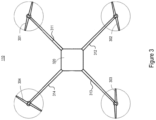
- FIG 3 shows an exemplary top down plan view of UAV 110.
- the UAV 110 includes a main body 320 that houses one or more of the components described as being included in the UAV 110 according to the description related to the exemplary block diagram for UAV 110 in Figure 2 .
- the UAV 110 shown in Figure 3 also includes four propeller blades 301, 302, 303, 304, where each of the four propeller blades 301, 302, 303, 304 are connected to the main body 320 by respective control bars 311, 312, 313, 314.
- the UAV 110 may include a single propeller blade in a helicopter embodiment, or any number of propeller blades according to different embodiments.
- the UAV 110 may travel to the target location where the target vehicle is predicted to be located (402).
- the UAV 110 may communicate with the GPS 170 to identify its own location, as well as to identify the target location.
- the UAV 110 may be operating autonomously according to the received operational commands.
- the UAV 110 may be operating according to the received operational commands as well as updated operational commands continuously received from the UAV command server 160 while the UAV 110 is operational (e.g., in-flight).
- the vehicle identifier may be referenced to identify the vehicle from which the vehicle identifier was obtained (407). For example, the vehicle identifier may be compared to a database of known vehicles and their respective vehicle identifier(s) to look up the vehicle corresponding to the vehicle identifier recognized from the image. By identifying the vehicle from the vehicle identifier recognized from the image, the vehicle depicted in the image may be determined to be the target vehicle. A results message may be transmitted back to the UAV 110 that confirms whether the vehicle identified from the recognized vehicle identifier matches the target vehicle.
- the results message may additionally include an operational command to capture an image of another vehicle within the target area to implement the process for identifying a vehicle through the operation of UAV 110 described by the flow diagram of logic 400.
- the UAV 110 may control the deployed attachments to gather respective measurements (504). For example, digital images or videos may be captured by the digital camera attachment that depicts the target vehicle. A color measurement may be obtained by the color meter from a portion of the target vehicle. A temperature measurement may be obtained by the thermographic camera from a portion of the target vehicle. An odor measurement may be obtained by the electronic nose device from a portion of the target vehicle. A distance measurement may be obtained by the distance measuring device (e.g., sonar based device or LIDAR based device) between an object and the target vehicle. In addition or alternatively, the distance measuring device may include a passive infrared sensor, a microwave radiation sensor, an ultrasonic sensor, or a tomographic motion detector to generally detect motion.
- the distance measuring device may include a passive infrared sensor, a microwave radiation sensor, an ultrasonic sensor, or a tomographic motion detector to generally detect motion.
- the UAV 110 may store the measurement information for analysis by the UAV 110 (505).
- the UAV 110 may further transmit the measurement information to an offsite computing device (e.g., UAV command server 160, the booth controller 120, or the vehicle information server 140) for analysis by the offsite computing device (505).
- an offsite computing device e.g., UAV command server 160, the booth controller 120, or the vehicle information server 140
- digital images or videos captured by the digital camera attachment may be analyzed to detect specific objects depicted in the image.
- a color measurement obtained by the color meter may be analyzed to determine a color on a portion of the target vehicle from which the color measurement was taken.
- a temperature measurement obtained by the thermographic camera may be analyzed to determine a temperate of a portion of the target vehicle from which the temperature measurement was taken.
- the UAV 110 may travel to the target location where the target vehicle is predicted to be located (702).
- the UAV 110 may communicate with the GPS 170 to identify its own location, as well as to identify the target location.
- the UAV 110 may be operating autonomously according to the received operational commands.
- the UAV 110 may be operating according to the received operational commands as well as updated operational commands continuously received from the UAV command server 160 while the UAV 110 is operational (e.g., in-flight).
- the UAV 110 may capture a digital image that depicts a vehicle identifier from a vehicle within the target location (703).
- the UAV 110 may determine it is at the target location by comparing location information obtained from communicating with the GPS 170 and the location information from the operational commands.
- the image may be captured by a digital camera included in the attachment assembly 216 of the UAV 110.
- the image may be initially stored within a memory of the UAV 110.
- the image may be analyzed according to known image recognition processes and algorithms (706). For example, the image may be analyzed to recognize alphanumeric characters corresponding to a vehicle identifier in the form of a VIN by comparing the shapes recognized from the analyzed image to known alphanumeric shapes. The image may also be analyzed to recognize a vehicle identifier in the form of a barcode or QR code by comparing the shapes recognized from the analyzed image to known barcode or QR code decoding algorithms. A vehicle identifier may be determined based on the analysis.
- the UAV 110 captures additional images of the vehicle using the digital camera (1006).
- the vehicle profile image requirements may call for the vehicle images uploaded to the vehicle profile to meet certain criteria.
- the vehicle template obtained from the vehicle profile may help the UAV 110 meet these criteria when capturing the vehicle images.
- one criteria may require the vehicle profile image to be a head-on image of the front-end of the vehicle.
- the vehicle template 1101 provides an outline that would result in the head-on image of the front-end of a vehicle 1102. In the field of view 1 100, the vehicle 1102 is shown to not yet fit within the vehicle template 1101.
- the UAV 110 may process the vehicle dimensions obtained from the vehicle profile and the UAV's GPS coordinates to map a flight path for the UAV 110 to travel around to specific locations around the vehicle's perimeter. For example, the UAV 110 may generate the flight path to locations that are a specific distance away from the front of the vehicle, driver side of the vehicle, rear of the vehicle, and passenger side of the vehicle. So by understanding the vehicle dimensions, the UAV 110 is able to generate the flight path and control the UAV 110 to travel to specific GPS coordinates on the flight path around the vehicle to capture additional vehicle images. The additional vehicle images may be uploaded to the vehicle profile stored on the data center 150.
- the UAV 110 may position itself relative to a vehicle in a predetermined manner (e.g., the UAV 110 may position itself so that the windshield is square in the field of view of the digital camera). After which, using the vehicle dimensions as determined by the scanned VIN and the GPS coordinates, the UAV 110 may move in a predetermined sequence in order to take a series of photographs. Specifically, after positioning itself square with the windshield of the vehicle, the UAV 110 may move backward 2 feet in order to take a first picture of the front of the vehicle. After which, the UAV 110 may move 4 feet to the right, move 5 feet forward and rotate 90° to take a picture of the right side of the vehicle. Thereafter, the UAV 110 may move in a predetermined fashion to take other pictures of the vehicle.
- a predetermined manner e.g., the UAV 110 may position itself so that the windshield is square in the field of view of the digital camera.
- additional vehicle images may be captured based on the obtained onboard vehicle information.
- the UAV 110 may analyze this information, generate predicted scenarios that could have caused the airbag deployment, and modify the flight path of the UAV 110 to capture images of the vehicle affected by the predicted scenarios.
- One predicted scenario may include a front-end collision, which causes the UAV 110 to modify the flight path to travel to a front-end of the vehicle to capture an image of the front-end of the vehicle that may show signs of a front-end collision predicted to have caused the airbag deployment.
Description
- This application claims priority to
U.S. Patent Application No. 15/367,510, filed December 2, 2016 - This disclosure relates to an unmanned aerial vehicle (UAV) including an attachment assembly for obtaining measurements.
- With rapid advances in network connectivity and UAV technology, the range of UAVs to travel greater distances from a command center has grown. With the ability to travel greater distances, the tasks and responsibilities assigned to UAVs have similarly grown.
- It is known from
US Patent No. 9,508,263 (Teng Yifei et al - It is known from US Patent Application
US2016/078759 (Nerayoff Steven David et al ) to provide tracking of a vehicle using an unmanned aerial vehicle. First images of the vehicle are received from a first camera of the unmanned aerial vehicle located at a first location. A unique identifier of a vehicle is determined to be unidentifiable in the first images. The unmanned aerial vehicle is then repositioned and second images of the vehicle are received. The unique identifier of the vehicle is then determined based on the second images. - According to the invention there is provided an unmanned aerial vehicle according to the characterising portion of claim 1.
-
-
Figure 1 shows an exemplary vehicle management system that includes an unmanned aerial vehicle (UAV). -
Figure 2 shows a block diagram for an exemplary UAV. -
Figure 3 shows an exemplary top down plan view of a UAV. -
Figure 4 shows a flow chart of logic describing an exemplary process for identifying a vehicle through the operation of a UAV. -
Figure 5 shows a flow chart of logic describing an exemplary process for modifying a UAV operation based on state information gathered by an attachment of the UAV. -
Figure 6 shows an exemplary vehicle management area within range of a UAV. -
Figure 7 shows a flow chart of logic describing an exemplary process for locating a target vehicle by a UAV. -
Figure 8 shows a flow chart of logic describing an exemplary process for modifying a UAV operation based on vehicle attribute information detected by a UAV. -
Figure 9 shows exemplary computer architecture for a computer system. -
Figure 10 shows a flow chart of logic describing an exemplary process for obtaining information from a vehicle via a UAV. -
Figure 11 shows an exemplary graphical user interface presented within a viewfinder of a UAV. - The discussion below makes reference to a vehicle management system that includes the control and operation of a UAV. The UAV is constructed to include flight components for achieving unmanned flight, processing components for processing information, and uses an attachment assembly, which includes one or more attachment devices for obtaining respective state observation measurements. The attachment assembly may comprise one, any combination, or all of the following: a digital camera for capturing a digital image (or a series of images); a color meter for measuring a paint color; a thermographic camera for measuring infrared radiation; an electronic nose device for measuring odors; and/or an electronic distance measuring device for measuring a distance between objects. The UAV may further include a wireless communication interface for wirelessly communicating (e.g., receiving and/or transmitting) information with other computing devices that are within range of the UAV's wireless communication interface.
- With these enhanced technological capabilities, and the additional range afforded to the UAV, the UAV may be utilized by the vehicle management system to achieve a number of sophisticated tasks.
-
Figure 1 shows an exemplaryvehicle management system 100 that includes UAV 110. Thevehicle management system 100 further includes Global Positioning Satellite (GPS) 170,UAV command server 160,booth controller 120,vehicle information server 140, anddata center 150. - Each of the components included in the
vehicle management system 100 may be connected via anetwork 130 to allow for communication of information to and from each of the components that are connected to thenetwork 130. Thenetwork 130 may be one or more of the following: a local area network; a wide area network; or any other network (such as a cellular communication network) that enables communication of data between computing communication devices. In one embodiment,network 130 may support wireless communications. Alternatively, or in addition,network 130 may support hard-wired communications, such as a telephone line or cable. Network 130 may also support the Ethernet IEEE (Institute of Electrical and Electronics Engineers) 802.3x specification. Network 130 may be the Internet and may support IP (Internet Protocol).Network 130 may be a LAN or a WAN. Network 130 may be a hotspot service provider network. Network 130 may be an intranet. Network 130 may be a GPRS (General Packet Radio Service) network. Network 130 may be any appropriate cellular data network or cell-based radio network technology. Network 130 may be an IEEE 802.11 wireless network or any suitable network or combination of networks. Although onenetwork 130 is shown inFigure 1 ,network 130 may be representative of any number of networks (of the same or different types) that may be utilized. - The
network 130 may couple one or more computing devices that may interact with data captured and/or stored by the other components of thevehicle management system 100. For example, thenetwork 130 may be coupled to a desktop computer, a laptop computer, or a mobile device such as a smart phone, tablet computer, or smart watch, that interacts with the data captured and/or stored by theUAV 110 or other components of thevehicle management system 100. - According to embodiments where the
network 130 is coupled to a smart watch, the smart watch may be configured to allow for an inspector of a vehicle to communicate with theUAV 110 over thenetwork 130 in real-time. For example, the inspector may input one or more of the following voice commands to the smart watch: "drone 123: please inspect vehicle X"; "drone 123: please detect smog." When the UAV 110 receives a voice command to detect smog, the UAV 110 may enter a smog inspection mode for conducting an emissions test on the vehicle. As part of the smog inspection mode, the UAV 110 may first control the vehicle to rev its engine to a predetermined speed (e.g., rotations per minute "RPM") while in park. To achieve this, the UAV 110 may send a command to the vehicle to rev the engine to the predetermined RPM. In addition or alternatively, the UAV 110 may communicate with an original equipment manager (OEM) service such as, for example OnStar, so that the OEM service controls the vehicle to rev the engine to the predetermined RPM. The UAV 110 may include sniffer components for measuring the different smog particles and products in the vehicle's emissions. - As another part of the smog inspection test administered by the
UAV 110, theUAV 110 may send a command to the vehicle to turn on both the left and right blinkers to inspect the blinkers. The UAV 110 may communicate wirelessly with a microprocessor on the vehicle to determine whether the blinkers are working. In addition or alternatively, the UAV 110 may be equipped with a light sensor component for directly measuring a light emitted from the vehicle's blinkers. - As another part of the smog inspection test, the UAV 110 may inspect certain vehicles (e.g., trucks) by measuring a weight of the vehicle. The UAV 110 may be equipped with an attachment for attaching to the vehicle, where a weight of the vehicle is measured based on a tension force exerted on the attachment as the
UAV 110 attempts to fly away from the vehicle while the attachment is attached to the vehicle. - In addition to communicating through the
network 130, the UAV 110 may communicate directly, via wireless communication protocols, with one or more of the components described as being included in thevehicle management system 100 when the UAV 110 is within wireless communication range of the components. For example, the UAV 110 may include a wireless communication interface configured for direct wireless communication with another computing device according one or more known wireless communication protocols. Each wireless communication protocol may have its own distinct range for communicating with another computing device. A more detailed description of theUAV 110 is provided with reference toFigure 2 . - The data captured and/or stored by the other components of the
vehicle management system 100 may be stored, for example, by theUAV 110 or may be routed by thevehicle information server 140 to be stored on thedata center 150. Thedata center 150 may include a high density array of network devices, includingcloud storage databases 151, andhost servers 152. Thehost servers 152 support a unique set of computing functionality offered by thevehicle information server 140. - The
vehicle information server 140 may store vehicle information gathered for a particular vehicle into a vehicle profile. One or more vehicle profiles may then be stored in thevehicle information server 140, or routed by thevehicle information server 140 to be stored on thecloud storage databases 151, according to vehicle identification information that identifies respective vehicles. Vehicle identification information may be, for example, a vehicle's unique VIN, license plate number, auction identification number when the vehicle has been processed into an auction database, or other unique identifier corresponding to the vehicle. - The vehicle information gathered by the
vehicle information server 140 for inclusion into a vehicle profile may include a vehicle history report (VHR) that includes, for example, accidents reported for a vehicle. The VHR may be retrieved from a department of motor vehicles, vehicle title database, or third party reporting services. Thevehicle information server 140 may further retrieve estimated value reports (EVR) on the vehicle from third party evaluation services, and include the retrieved EVR into a vehicle's vehicle profile. The EVR may describe a predicted price a client may expect to be able to resale the vehicle for, as well as an amount a client may expect to pay wholesale for the vehicle. Alternatively, or in addition, thevehicle information server 140 may retrieve make, model, vehicle build reports describing the vehicle attributes, and/or vehicle recall information obtained from a vehicle manufacturer, and include this information into a vehicle's vehicle profile. Thevehicle information server 140 may further retrieve vehicle title information from a title holding entity, and include the title information into a vehicle profile. With the information gathered by thevehicle information server 140, a vehicle profile may include vehicle specifications, vehicle condition reporting (e.g., junk, salvage, total loss), vehicle title reporting, vehicle odometer readings, vehicle recall information, as well as other vehicle specific information such as evidence of past sales or past offers for sale (e.g., identifying past offers for sale on an online auction website), existing liens on the vehicle obtained from financial institutions, and vehicle accident reports obtained from police accident reports. - In one embodiment, when the
UAV 110 obtains vehicle identification information (e.g., obtains a vehicle identifier), as described by one or more of the processes described herein, theUAV 110 may further transmit a request to thevehicle information server 140. The request may include the vehicle identification information obtained by theUAV 110, as well as a request for vehicle information corresponding to the vehicle identification information. For example, theUAV 110 may transmit a request to thevehicle information server 140 through thenetwork 130, or alternatively, control a wireless communication interface on theUAV 110 to directly transmit the request to thevehicle information server 140 according to a wireless communication protocol. In response to receiving the request, thevehicle information server 140 may parse a database of vehicle profiles to locate a vehicle profile matching the vehicle identification information included in the request. After identifying the vehicle profile matching the vehicle identification information included in the request, thevehicle information server 140 may return the matching vehicle profile back to theUAV 110. According to some embodiments, thevehicle information server 140 may further generate a vehicle report based on the matching vehicle profile, and return the vehicle report to theUAV 110 along with the matching vehicle profile. - The
UAV 110 may also have access to a shipping report that may be included in the vehicle report. The shipping report may identify vehicles based on their respective VIN numbers, and also describes vehicle equipment at the time the vehicles were shipped based on their VIN numbers. By accessing the shipping report, theUAV 110 may understand after-market add-ons to a vehicle that were not identified as part of the original equipment on the vehicle at the time of shipping. For example, when theUAV 110 detects a trailer hitch or roof rack that was not identified as part of the original equipment in the shipping report, theUAV 110 may determine such new equipment is either after-market or at least not part of the vehicle's original equipment. In one embodiment, theUAV 110 may be responsible for running the analysis to populate the shipping report. In another embodiment, theUAV 110 may access the shipping report from a third part source. - After receiving the vehicle profile, the
UAV 110 may analyze the vehicle profile to generate a vehicle report. When a vehicle report generating application is installed on theUAV 110, theUAV 110 may directly generate the vehicle report based on the information included in the vehicle profile. In addition or alternatively, theUAV 110 may transmit the vehicle profile to thebooth controller 120, where thebooth controller 120 has installed the vehicle report generating application that analyzes the vehicle profile and generates the vehicle report based on the analysis. The vehicle report may include a vehicle inspection form that includes instructions and other information tailored for the vehicle identified by the corresponding vehicle profile. In one embodiment, the vehicle inspection form includes one or more fields that are pre-populated with information received from theUAV 110. As one example, the vehicle inspection form may include the vehicle identification information (e.g., the VIN) pre-populated in the form. As another example, the vehicle inspection form may be pre-populated with measurements taken by an attachment assembly of the UAV 110 (e.g., vehicle color, recognition of vehicle damage, recognition of vehicle accessories, distance between vehicle and another specified object). The vehicle report may further be generated to include tailored vehicle inspection protocols that identify inspection instructions that are relevant to the vehicle identified by the corresponding vehicle profile. For example, when the vehicle profile identifies a model year 2014 Ford F-150 truck in a XLT trim, the respective vehicle report may identify specific inspection instructions that are tailored for the vehicle due to its known larger dimensions, as well as instructions for inspecting vehicle specific parts that are known to have higher rates of failure as described in the vehicle profile (e.g., recall notices that are related to the model year 2014 Ford F-150 truck in a XLT trim). - The
booth controller 120 may, for example, be part of a vehicle documentation booth as described byU.S. Patent Application No. 14/477,615 , the entire contents of which are hereby incorporated by reference herein. - The
UAV command server 160 may be a computing device configured to communicate operational commands to theUAV 110. The operational commands may include flight path plans for controlling aerial movement and positioning of theUAV 110. The operational commands may also include instructions for operating an attachment assembly included on theUAV 110. In operation, theUAV 110 may receive operational commands from theUAV command server 160, execute the operational commands, which then cause theUAV 110 to operate according to the flight path plans and instructions described by the operational commands. TheUAV command server 160 may also keep track of theUAV 110's position by communicating with theUAV 110 directly, or by communicating theGPS 170 that is tracking theUAV 110. - The
UAV command server 160 may also modify operational commands based on information received from one or more of the component devices included in thevehicle management system 100. For example, the vehicle profile and/or vehicle report may be received by theUAV command server 160 from theUAV 110,vehicle information server 140, orbooth controller 120. - It follows that the
vehicle management system 100 shown inFigure 1 is enhanced by the advanced capabilities of theUAV 110 to accomplish a variety of unique tasks. For example, theUAV 110 may be operated to travel to a target location, where the target location may be described as the location of a target vehicle. After theUAV 110 confirms it has arrived at the target location, theUAV 110 may implement procedures to identify the target vehicle by scanning a vehicle identification number (VIN) on the target vehicle. As the target location may include more than one vehicle, theUAV 110 may be operated to scan more than one vehicle for its VIN to identify the respective target vehicle. TheUAV 110 may also be operated to identify the target vehicle by capturing a digital image of one or more vehicles that are within the target location, and analyzing the digital image according to an image recognition processes to detect vehicle identifiers that may be relied on to identify the vehicles. Vehicle identifiers may include an alphanumeric VIN or other identifying set of numbers/letters (e.g., model number, license plate), or unique vehicle characteristics that may be relied upon to identify the vehicle (e.g., vehicle shape, size, unique characteristics such as wheel design, color, or specialty trim). By analyzing the vehicle identifier for one or more of the vehicles depicted in the digital image, theUAV 110 may be able to identify the target vehicle. - The
UAV 110 may further be operated to travel to the target location, locate the target vehicle within the target location, and initiate a locksmith process for unlocking the target vehicle. For example, theUAV 110 may receive unlock codes for unlocking the target vehicle doors from theUAV command server 160 as part of operational commands received from theUAV command server 160. After confirming identification of the target vehicle, theUAV 110 may transmit the unlock codes to the target vehicle, similar to the wireless unlocking feature found on key fobs. TheUAV 110 may transmit an unlock confirmation signal to theUAV command server 160 after confirming successful unlock of the target vehicle. In one embodiment, the timing of theUAV command server 160 sending the unlock code to theUAV 110 may be dependent on one or more conditions. For example, theUAV command server 160 may monitor the location of theUAV 110 and another electronic device, such ascomputing device 620, discussed below. In particular, theUAV command server 160 may monitor the locations of both theUAV 110 and thecomputing device 620 with respect to a target vehicle, and send the unlock code to theUAV 110 when both theUAV 110 and thecomputing device 620 are within a predetermined distance(s) of the target vehicle. - The
UAV 110 may further be operated to travel to the target location, locate the target vehicle within the target location, and initiate an information transfer process with the target vehicle. For example, the target vehicle may be equipped with a vehicle history dongle that records vehicle characteristics while the target vehicle is operated. For example, the vehicle history dongle may record temperature readings measured by temperature sensors within an engine bay of the target vehicle. The vehicle history dongle may record vibration/shock readings measured by vibration/shock sensors (e.g., accelerometer, gyroscope, or piezoelectric sensors) on the target vehicle or included in the vehicle history dongle, where the measured vibrations or shocks may indicate an accident involving the target vehicle has occurred. The vehicle history dongle may record acceleration readings measured by an accelerometer on the target vehicle or included in the vehicle history dongle. By recording such information, the vehicle history dongle may generate a vehicle driving report for the target vehicle based on the recorded information. The vehicle driving report may describe a driving style (e.g., passive, moderate, aggressive) as well as a driving history derived from an analysis of the recorded information. - Some dongles may be equipped to start the vehicle. For example, authorized OEM dongles may be configured to start the vehicle directly or from commands received from an OnStar service. When an OnStar service or dongle is allowed to start the vehicle, the
UAV 110 may subsequently detect operational issues on the vehicle after the vehicle starts its engine. For example, sniffers or smoke sensors on theUAV 110 may detect smoke from the vehicle following the vehicle start. Because the vehicle's engine has started and the vehicle may be moving, theUAV 110 may also include anti-collision software to operate theUAV 110 to avoid collision with the vehicle that theUAV 110 is observing to detect the measurements from. - The
UAV 110 may be operated to generally travel to a target area (e.g., parking lot, vehicle auction lot, car dealer lot, rental vehicle lot), identify one or more vehicles within the target area, and generate a map that locates one or more of the identified vehicles to their respective location within the target area. In this way, theUAV 110 may generate an accurate map and location key identifying the location of vehicles within the target area. - The
UAV 110 may further be operated to utilize attachments from an attachment assembly to obtain state measurements related to the target vehicle. For example, theUAV 110 may activate a color meter attachment to measure a paint color of the target vehicle, a thermographic camera to measure infrared radiation emitting from the target vehicle, an electronic nose device to measure odors emitting from the target vehicle, or an electronic distance measuring device to measure a distance between the target vehicle and surrounding objects. - The
UAV 110 may further be operated to transmit information obtained by the UAV 110 (e.g., state information obtained by an attachment from the UAV attachment assembly, vehicle profile, or vehicle report) to another computing device for additional analysis. - The
UAV 110 may further be operated to travel to a target location described as including the target vehicle, confirm the identification of the target vehicle, and capture a digital image of a driver and/or passenger of the target vehicle. The digital image may be analyzed under facial recognition software to identify the faces. The faces recognized from the digital image may be compared against a database that stores facial information of one or more known people associated with the target vehicle to verify the target vehicle is being operated or otherwise occupied by a person associated with the target vehicle. The faces recognized from the digital image may also be compared against a database that stores faces of one or more known people associated with an application to verify whether one or more faces recognized from the digital image matches up to a registered user of the application. The application may be an application being executed by the target vehicle that requires user verification, which may be verified by theUAV 110 as described. After confirming verification of the driver and/or a passenger in the target vehicle, a verification signal may be transmitted to theUAV command server 160, or another server associated with, for example, the application. - A microphone and/or speaker may be included in the
UAV 110 so that theUAV 110 may recognize a driver or other person interacting with theUAV 110 or vehicle that is being observed by theUAV 110. For example, theUAV 110 may receive identification information from a person who identifies himself for authentication by theUAV 110. So when a person says "My name is Jim," this speech pattern is received by the microphone on theUAV 110 and theUAV 110 is able to run a voice recognition process on the person's voice to authenticate the person. The voice recognition process may be combined with other security features such as facial recognition and location information. For example, facial recognition may be run on the person who provided the speech pattern to better authenticate the person. In addition, location information on the person may be referenced to determine whether the person can be in their current location. For example, when theUAV 110 receives information indicating a vehicle's owner is on vacation in Mexico, and a person is attempting to authenticate themselves as the vehicle owner in Illinois, theUAV 110 will recognize the person is likely not the vehicle owner. After theUAV 110 authenticates the vehicle owner, theUAV 110 may receive voice commands from the authenticated vehicle owner to transmit to the vehicle (e.g., "unlock door"; "roll down windows"; "turn on left/right turn signals"; "rev engine to X RPM"). - One or more of the computing devices in the
vehicle management system 100 may include one or more components described by the exemplary computer architecture ofcomputer system 900 inFigure 9 . -
Computer system 900 includes anetwork interface 920 that allows communication with other computers via anetwork 926, wherenetwork 926 may be represented bynetwork 130 inFigure 1 .Network 926 may be any suitable network and may support any appropriate protocol suitable for communication tocomputer system 900. Thecomputer system 900 may also include aprocessor 902, amain memory 904, astatic memory 906, an output device 910 (e.g., a display or speaker), aninput device 912, and astorage device 916, communicating via abus 908. -
Processor 902 represents a central processing unit of any type of architecture, such as a CISC (Complex Instruction Set Computing), RISC (Reduced Instruction Set Computing), VLIW (Very Long Instruction Word), or a hybrid architecture, although any appropriate processor may be used.Processor 902 executesinstructions 924 stored on one or more of themain memory 904,static memory 906, orstorage device 916.Processor 902 may also include portions of thecomputer system 900 that control the operation of theentire computer system 900.Processor 902 may also represent a controller that organizes data and program storage in memory and transfers data and other information between the various parts of thecomputer system 900. -
Processor 902 is configured to receive input data and/or user commands throughinput device 912.Input device 912 may be a keyboard, mouse or other pointing device, trackball, scroll, button, touchpad, touch screen, keypad, microphone, speech recognition device, video recognition device, accelerometer, gyroscope, global positioning system (GPS) transceiver, or any other appropriate mechanism for the user to input data tocomputer system 900 and control operation ofcomputer system 900.Input device 912 as illustrated inFigure 9 may be representative of any number and type of input devices. -
Processor 902 may also communicate with other computer systems vianetwork 926 to receiveinstructions 924, whereprocessor 902 may control the storage ofsuch instructions 924 into any one or more of the main memory 904 (e.g., random access memory (RAM)), static memory 906 (e.g., read only memory (ROM)), or thestorage device 916.Processor 902 may then read and executeinstructions 924 from any one or more of themain memory 904,static memory 906, orstorage device 916. Theinstructions 924 may also be stored onto any one or more of themain memory 904,static memory 906, orstorage device 916 through other sources. Theinstructions 924 may correspond to, for example, instructions and/or operational commands for controlling operation of theUAV 110. - Although
computer system 900 is represented inFigure 9 as asingle processor 902 and asingle bus 908, the disclosed embodiments applies equally to computer systems that may have multiple processors and to computer systems that may have multiple busses with some or all performing different functions in different ways. -
Storage device 916 represents one or more mechanisms for storing data. For example,storage device 916 may include a computerreadable medium 922 such as read-only memory (ROM), RAM, non-volatile storage media, optical storage media, flash memory devices, and/or other machine-readable media, or any other appropriate type of storage device. Although only onestorage device 916 is shown, multiple storage devices and multiple types of storage devices may be present. Further, althoughcomputer system 900 is drawn to contain thestorage device 916, it may be distributed across other computer systems that are in communication withcomputer system 900, such as a computer system in communication withcomputer system 900. For example, whencomputer system 900 is representative of thevehicle information server 140,storage device 916 may be distributed across to include thedata center 150. -
Output device 910 is configured to present information to the user. For example,output device 910 may be a display such as a liquid crystal display (LCD), a gas or plasma-based flat-panel display, or a traditional cathode-ray tube (CRT) display or other well-known type of display in the art of computer hardware. Accordingly,output device 910 may be a device for displaying a user interface. In addition or alternatively,output device 910 may be a speaker configured to output audible information to the user. In addition or alternatively,output device 910 may be a haptic output device configured to output haptic feedback to the user. Any combination of output devices may be represented by theoutput device 910. -
Network interface 920 provides thecomputer system 900 with connectivity to thenetwork 926 through any compatible communications protocol.Network interface 920 sends and/or receives data from thenetwork 926 via a wireless orwired transceiver 914.Transceiver 914 may be a cellular frequency, radio frequency (RF), infrared (IR) or any of a number of known wireless or wired transmission systems capable of communicating withnetwork 926 or other computer device having some or all of the features ofcomputer system 800.Bus 908 may represent one or more busses, e.g., USB, PCI, ISA (Industry Standard Architecture), X-Bus, EISA (Extended Industry Standard Architecture), or any other appropriate bus and/or bridge (also called a bus controller).Network interface 920 as illustrated inFigure 9 may be representative of a single network interface card configured to communicate with one or more different data sources. -
Computer system 900 may be implemented using suitable hardware, software and/or circuitry, such as a personal computer or other electronic computing device. In addition,computer system 900 may also be a portable computer, laptop, tablet or notebook computer, PDA, pocket computer, appliance, telephone, server computer device, or mainframe computer. -
Figure 2 shows an exemplary block diagram forUAV 110. TheUAV 110 may include acommunication interface 202,analysis logic circuitry 204, and adisplay screen 206. TheUAV 110 may further include input/output (I/O) interfaces 212,flight components 214,attachment assembly 216,GPS circuitry 218, andpower source 220. - The
communication interface 202 may include Universal Serial Bus (USB) interfaces, audio outputs, magnetic or optical media interfaces (e.g., a CDROM or DVD drive), network (e.g., Ethernet or cable (e.g., DOCSIS) interfaces), Serial Advanced Technology Attachment (SATA), and Peripheral Component Interconnect express (PCIe) interfaces and connectors, memory card slots or other types of serial, parallel, or network data interfaces. Thecommunication interface 202 may include one or more Ethernet ports, or any other type of wired or wireless communication interface. For example, thecommunication interface 202 may include a communication interface for bi-directional communication of instructions / commands / data with thebooth controller 120,UAV command server 160, andvehicle information server 140. - The
display screen 206 may present, for example, a graphical user interface (GUI) 208. TheGUI 208 may display and accept user parameters, and annotation commands throughinterface elements 210. Theinterface elements 210 may visualize, as just a few examples, images, input fields, or any other information or measurements captured by theUAV 110. Theinterface elements 210 may also be directive interface element, such as a button, hyperlink, or any other interface element to provide a command or instruction. TheGUI 208 may further present the information captured by theUAV 110 as a direct display on thedisplay screen 206, or through an aggregated information portal, such as a web page. The captured information may be annotated with further information received from thebooth controller 120,UAV command server 160, andvehicle information server 140, which theanalysis logic circuitry 204 may request. - The I/O interfaces 212 may correspond to the
input device 912 and/oroutput device 910 described by thecomputer system 900. For example, the I/O interfaces 212 may include one or more of a keyboard, mouse, voice recognition, touchscreen, and any other type of input mechanisms for operator interaction with theUAV 110,booth controller 120, orUAV command server 160. Additional examples of the I/O interfaces 212 include microphones, video and still image cameras, temperature sensors, vibration sensors, rotation and orientation sensors, radiation sensors (e.g., IR or RF sensors), and other types of inputs. - The
flight components 214 may include the hardware, software, circuitry, and mechanics enabling theUAV 110 for airborne travel. This includes one or more of propellers, motors, digital cameras, distance sensors, and/or accelerometers. In particular, theflight components 214 may include two or more propeller assemblies for enabling theUAV 110 for airborne travel. - The
analysis logic circuitry 204 may include a combination of hardware, software, and/or circuitry. For example, theanalysis logic circuitry 204 may include one ormore processors 222 andmemories 224. Thememory 224 may store instructions 226 (e.g., program instructions) for execution by theprocessor 222. Theanalysis logic circuitry 204 may include an application customized for mobile devices and operating systems, such as for example Android, iOS, WebOS, Blackberry, or any other mobile device. This may allow any mobile device with the mobile application installed to effectively control theUAV 110. Thememory 224 may also store the information received at thecommunication interface 202, such as sensor measurements captured byattachment assembly 216. - The
attachment assembly 216 may include one or more attachments. For example, theattachment assembly 216 may include a digital camera to capture a digital image, a color meter to measure a paint color, a thermographic camera to measure infrared radiation, an electronic nose device to measure odors, and/or an electronic distance measuring device to measure a distance between objects. - The
GPS circuitry 218 may include a transceiver for communicating location information to and fromGPS 170. -
Power source 220 may be a rechargeable battery such as a lead acid based rechargeable battery, nickel cadmium (NiCd) based rechargeable battery, nickel metal hydride (NiMH) based rechargeable battery, lithium ion (Li-ion) based rechargeable battery, or lithium ion polymer (Li-ion polymer) based rechargeable battery. Thepower source 220 may further include solar energy capturing photovoltaic cells for assisting in the recharging of the rechargeable battery. - As will be described in more detail below, the
commands 228 may include an original set of commands included with theinstructions 226 for operating theUAV 110. Thecommands 228 may also correspond to revised commands or new commands transmitted from theUAV command server 160 during operation of theUAV 110. The measurements obtained by an attachment of theattachment assembly 216 may be stored asdata 230 in thememory 224. Thedata 230 may further be transmitted to thebooth controller 120,UAV command server 160, and/orvehicle information server 140. -
Figure 3 shows an exemplary top down plan view ofUAV 110. TheUAV 110 includes amain body 320 that houses one or more of the components described as being included in theUAV 110 according to the description related to the exemplary block diagram forUAV 110 inFigure 2 . TheUAV 110 shown inFigure 3 also includes fourpropeller blades propeller blades main body 320 byrespective control bars UAV 110 may include a single propeller blade in a helicopter embodiment, or any number of propeller blades according to different embodiments. -
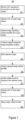
Figure 4 shows an exemplary flow diagram oflogic 400 describing an exemplary process for identifying a vehicle through the operation ofUAV 110. For example, theUAV 110 may receive, from theUAV command server 160, operational commands for locating a target vehicle (401). The operational commands may include at least a description of the target vehicle and a target location where the target vehicle is predicted to be located. The target vehicle description may include a vehicle identification number (VIN), as well as physical characteristics of the target vehicle such as color, make, model, special equipment, or known physical defects. The target location may be described in terms of latitude and longitude measurements. - Based on the information provided by the received operational commands, the
UAV 110 may travel to the target location where the target vehicle is predicted to be located (402). TheUAV 110 may communicate with theGPS 170 to identify its own location, as well as to identify the target location. TheUAV 110 may be operating autonomously according to the received operational commands. Alternatively, theUAV 110 may be operating according to the received operational commands as well as updated operational commands continuously received from theUAV command server 160 while theUAV 110 is operational (e.g., in-flight). - After determining that the
UAV 110 is at the target location, theUAV 110 may capture a digital image that depicts a vehicle identifier from a vehicle within the target location (403). TheUAV 110 may determine it is at the target location by comparing location information obtained from communicating with theGPS 170 and the location information from the operational commands. The image may be captured by a digital camera included in theattachment assembly 216 of theUAV 110. The image may be initially stored within a memory of theUAV 110. - The image may be transmitted to the
UAV command server 160 for image recognition analysis (404).
Alternatively in an arrangement not covered by the claims, the image may be transmitted to thebooth controller 120 or thevehicle information server 140 for image recognition analysis. Alternatively, theUAV 110 may perform the image recognition analysis. - The image may be stored on a memory of the computing device receiving the image (405). For example, the
UAV command server 160,booth controller 120,vehicle information server 140, orUAV 110 may store the image into a respective memory upon receipt. - The image may be analyzed according to known image recognition processes and algorithms (406). For example, the image may be analyzed to recognize alphanumeric characters corresponding to a vehicle identifier in the form of a VIN by comparing the shapes recognized from the analyzed image to known alphanumeric shapes. The image may also be analyzed to recognize a vehicle identifier in the form of a barcode or QR code by comparing the shapes recognized from the analyzed image to known barcode or QR code decoding algorithms. A vehicle identifier may be determined based on the analysis.
- The vehicle identifier may be referenced to identify the vehicle from which the vehicle identifier was obtained (407). For example, the vehicle identifier may be compared to a database of known vehicles and their respective vehicle identifier(s) to look up the vehicle corresponding to the vehicle identifier recognized from the image. By identifying the vehicle from the vehicle identifier recognized from the image, the vehicle depicted in the image may be determined to be the target vehicle. A results message may be transmitted back to the
UAV 110 that confirms whether the vehicle identified from the recognized vehicle identifier matches the target vehicle. When the vehicle identified from the recognized vehicle identifier does not match the target vehicle, the results message may additionally include an operational command to capture an image of another vehicle within the target area to implement the process for identifying a vehicle through the operation ofUAV 110 described by the flow diagram oflogic 400. - As described, according to some embodiments, the
UAV 110 may be operated to run the image recognition analysis on the image directly, recognize the vehicle identifier from the image, and determine whether the vehicle identified from the recognized vehicle identifier matches the target vehicle. - After the
UAV 110 verifies the target vehicle, additional processes specifically related to the target vehicle may be implemented. For example, theUAV 110 may communicate with thevehicle information server 140 to request a vehicle report on the target vehicle. TheUAV 110 may further communicate with theUAV command server 160, thebooth controller 120, or thevehicle information server 140 to request an examination report that identifies specific target vehicle related steps for examining the target vehicle. For example, when the vehicle report on the target vehicle identifies a collision to the front passenger side door, the target vehicle specific examination report will instruct theUAV 110 to examine the front passenger side door. The vehicle report may further identify an engine fire for the target vehicle, in which case the examination report may instruct theUAV 110 to examine the target vehicle's front hood. In one embodiment, theUAV command server 160 may review the vehicle report and, based on the review, instruct theUAV 110 to modify its operation (e.g., theUAV command server 160 determines, based on the vehicle report of a collision to the front passenger door, and in turn, instructs theUAV 110 to examine the front passenger door). In an alternative embodiment, theUAV 110 may review the vehicle report and, based on the review, modify its operation. -
Figure 5 shows an exemplary flow diagram oflogic 500 describing an exemplary process for deploying an attachment from theattachment assembly 216 of theUAV 110, gathering measurements from the deployed attachment, and modifying operation of theUAV 110 based on the gathered measurements. - The
UAV 110 may detect whether there is an attachment deployment state (501). The attachment deployment state may be an operational command received and executed by theUAV 110 that instructs the deployment of a specific attachment. The attachment deployment state may be related to a target vehicle presently being examined by theUAV 110. For example, theUAV 110 may examine the target vehicle by following an examination report specifically generated to account for characteristics of the target vehicle. - The
UAV 110 may determine an appropriate attachment to deploy from theattachment assembly 216 based on the detected attachment deployment state (502). For example, when the examination report instructs theUAV 110 to inspect the target vehicle's front passenger side door for collision damage and front hood for fire damage, theUAV 110 may determine to deploy the digital camera to capture pictures of the front passenger side door and the front hood, and further to deploy the electronic nose device to measure odors (i.e., smoke related odors) emitted from the front hood. TheUAV 110 may further deploy the color meter to measure a paint color of the front passenger side door and the front hood to detect paint variances from surrounding panels which may be referenced to determine whether new vehicle panels and parts were installed. - After determining the appropriate attachments to deploy, the
UAV 110 may deploy the appropriate attachments (503). - The
UAV 110 may control the deployed attachments to gather respective measurements (504). For example, digital images or videos may be captured by the digital camera attachment that depicts the target vehicle. A color measurement may be obtained by the color meter from a portion of the target vehicle. A temperature measurement may be obtained by the thermographic camera from a portion of the target vehicle. An odor measurement may be obtained by the electronic nose device from a portion of the target vehicle. A distance measurement may be obtained by the distance measuring device (e.g., sonar based device or LIDAR based device) between an object and the target vehicle. In addition or alternatively, the distance measuring device may include a passive infrared sensor, a microwave radiation sensor, an ultrasonic sensor, or a tomographic motion detector to generally detect motion. - The
UAV 110 may store the measurement information for analysis by the UAV 110 (505). TheUAV 110 may further transmit the measurement information to an offsite computing device (e.g.,UAV command server 160, thebooth controller 120, or the vehicle information server 140) for analysis by the offsite computing device (505). For example, digital images or videos captured by the digital camera attachment may be analyzed to detect specific objects depicted in the image. A color measurement obtained by the color meter may be analyzed to determine a color on a portion of the target vehicle from which the color measurement was taken. A temperature measurement obtained by the thermographic camera may be analyzed to determine a temperate of a portion of the target vehicle from which the temperature measurement was taken. An odor measurement obtained by the electronic nose device may be analyzed to determine an odor emitting from a portion of the target vehicle from which the odor measurement was taken. A distance measurement obtained by the distance measuring device (e.g., sonar based device or LIDAR based device) may be analyzed to determine a distance between an object and the target vehicle. - Operational commands for controlling the operation of the
UAV 110 may be modified and/or newly generated based on the measurement information (506). For example, when an object of interest is detected from the image captured by the digital camera, the operational commands may be modified to change the flight plan forUAV 110 to travel to a different position to capture a different view of the target vehicle. When a color measured by the color meter identifies a portion of the target vehicle has a color that is different from surrounding panels, the operational commands may be modified to change the flight plan forUAV 110 to travel to a different position to capture a different view of the target vehicle. When a temperature measured by the thermographic camera identifies a portion of the target vehicle exceeds a threshold temperature, the operational commands may be modified to change the flight plan forUAV 110 to travel to a different position to capture a different view of the target vehicle or to initiate a call to emergency services. When an odor detected by the electronic nose device is determined to match up to a known harmful gas or harmful condition, the operational commands may be modified to change the flight plan forUAV 110 to travel to a different position to capture a different view of the target vehicle or to initiate a call to emergency services. When an object detected by the electronic measuring device is determined to interfere with the UAV's 110 current flight plan, the operational commands may be modified to change the flight plan forUAV 110 to travel to a different position that does not interfere with the object. -
Figure 6 shows an exemplaryvehicle management area 600. Thevehicle management area 600 may be representative of, for example, a rental car lot, a car dealership lot, a parking lot, vehicle auction lot, or another target area. - Within the
vehicle management area 600, there may be one or more vehicles such asvehicle 601,vehicle 602,vehicle 603, andvehicle 604. Thevehicle management area 600 may further be partitioned into a plurality of sections. For example, when thevehicle management area 600 is representative of the vehicle auction lot, the partitioned sections may include a holdinglot 611 and anauction area 612. The holdinglot 611 may includevehicle 601,vehicle 602, andvehicle 603 that are included in the vehicle auction but not currently being bid on. Theauction area 612 includesvehicle 604 that is presently being bid on. - The
UAV 110 may be operated to locate and identify vehicles within thevehicle management area 600 according to any one or more of the processes described herein. TheUAV 110 may further be operated to deploy one or more attachments from theattachment assembly 216 to obtain measurements from vehicles within thevehicle management area 600. - According to some embodiments, the
UAV 110 may be operated according to operational commands transmitted from theUAV command server 160. According to some embodiments, theUAV 110 may be operated according to operational commands transmitted from acomputing device 620 such as a laptop computer, personal computer, or smartphone. According to some embodiments, theUAV 110 may operate autonomously after receiving an initial set of operational commands from either theUAV command server 160 orcomputing device 620. -
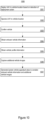
Figure 7 shows an exemplary flow diagram oflogic 700 describing an exemplary process for identifying and tracking a vehicle through the operation ofUAV 110. For example, theUAV 110 may receive, from theUAV command server 160, operational commands for locating a target vehicle (701). The operational commands including at least a description of the target vehicle and a target location where the target vehicle is predicted to be located. The target vehicle description may include a vehicle identification number (VIN), as well as physical characteristics of the target vehicle such as color, make, model, special equipment, or known physical defects. The target location may be described in terms of latitude and longitude measurements. - Based on the information provided by the received operational commands, the
UAV 110 may travel to the target location where the target vehicle is predicted to be located (702). TheUAV 110 may communicate with theGPS 170 to identify its own location, as well as to identify the target location. TheUAV 110 may be operating autonomously according to the received operational commands. Alternatively, theUAV 110 may be operating according to the received operational commands as well as updated operational commands continuously received from theUAV command server 160 while theUAV 110 is operational (e.g., in-flight). - After determining the
UAV 110 is at the target location, theUAV 110 may capture a digital image that depicts a vehicle identifier from a vehicle within the target location (703). TheUAV 110 may determine it is at the target location by comparing location information obtained from communicating with theGPS 170 and the location information from the operational commands. The image may be captured by a digital camera included in theattachment assembly 216 of theUAV 110. The image may be initially stored within a memory of theUAV 110. - The image may be transmitted to the
UAV command server 160 for image recognition analysis (704). Alternatively, the image may be transmitted to thebooth controller 120 or thevehicle information server 140 for image recognition analysis. Alternatively, theUAV 110 may commence the image recognition analysis. - The image may be stored on a memory of the computing device receiving the image (705). For example, the
UAV command server 160,booth controller 120,vehicle information server 140, orUAV 110 may store the image into a respective memory upon receipt. - The image may be analyzed according to known image recognition processes and algorithms (706). For example, the image may be analyzed to recognize alphanumeric characters corresponding to a vehicle identifier in the form of a VIN by comparing the shapes recognized from the analyzed image to known alphanumeric shapes. The image may also be analyzed to recognize a vehicle identifier in the form of a barcode or QR code by comparing the shapes recognized from the analyzed image to known barcode or QR code decoding algorithms. A vehicle identifier may be determined based on the analysis.
- The vehicle identifier may be referenced to identify the vehicle from which the vehicle identifier was obtained from (707). For example, the vehicle identifier may be compared to a database of known vehicles and their respective vehicle identifier(s) to look up the vehicle corresponding to the vehicle identifier recognized from the image. By identifying the vehicle from the vehicle identifier recognized from the image, the vehicle depicted in the image may be determined to be the target vehicle. A results message may be transmitted back to the
UAV 110 that confirms whether the vehicle identified from the recognized vehicle identifier matches the target vehicle. When the vehicle identified from the recognized vehicle identifier does not match the target vehicle, the results message may additionally include an operational command to capture an image of another vehicle within the target area to implement the process for identifying a vehicle through the operation ofUAV 110 described by the flow diagram oflogic 700. - As described, according to some embodiments the
UAV 110 may be operated to run the image recognition analysis on the image directly, recognize the vehicle identifier from the image, and determine whether the vehicle identified from the recognized vehicle identifier matches the target vehicle. - After the
UAV 110 verifies the target vehicle, additional processes specifically related to the target vehicle may be implemented. For example, theUAV 110 may be operated to track the target vehicle as the target vehicle travels to different locations (708). TheUAV 110 may maintain a predetermined distance from the target vehicle as theUAV 110 tracks the target vehicle to different locations. - As the
UAV 110 tracks the target vehicle, theUAV 110 may transmit location information back to theUAV command server 160 at predetermined time intervals (e.g., every 10 minute). -
Figure 8 shows an exemplary flow diagram oflogic 800 describing an exemplary process for modifying operation of theUAV 110 based on vehicle attribute information detected by theUAV 110. - The
UAV 110 may deploy an attachment to obtain a state observation measurement (801). The measurement information obtained by the attachment may be stored, at least temporarily, in theUAV 110. - The measurement information may be transmitted to the vehicle information server 140 (802). Target vehicle information corresponding to the vehicle from which the measurement information is obtained may further be transmitted to the
vehicle information server 140. Alternatively, the measurement information and/or the target vehicle information may be transmitted to theUAV command server 160,booth controller 120, or other remote computing device. The target vehicle information may include a vehicle report on the target vehicle, as well as other information describing the target vehicle. - The measurement information may be analyzed in view of the target vehicle information by the computing device receiving such information (803). For example, the measurement information may be compared against a set of operational commands that matches a predetermined operation command for a corresponding state observation measurement.
- The computing device having processed the analysis determines whether an actionable item is recognized based on the analysis (804). For example, when a comparison of the measurement information against the set of operational commands returns a match, an actionable item is determined to be recognized. As another example, recognizing a new physical characteristic of the target vehicle (e.g., new dent or scratch, new color, new accessories, new mileage) that is not identified in the target vehicle's vehicle report may be recognized as an actionable item.
- The
vehicle information server 140 may generate a new vehicle report or modify an existing vehicle report for the target vehicle to further describe the actionable item (805). Thevehicle information server 140, or other computing device, may further generate a new or modified examination report to account for the actionable item. - Operational commands for the
UAV 110 may be modified or newly generated in view of the modified or new vehicle report (806). For example, theUAV 110 orUAV command server 160 may receive the modified or new vehicle report from thevehicle information server 140, and generate new or modified operational commands for theUAV 110. The new or modified operational commands may include instructions for changing the UAV's 110 flight path, or control operation of attachments in theattachment assembly 216, to implement the operational commands corresponding to the actionable item. -
Figure 10 shows an exemplary flow diagram oflogic 1000 describing an exemplary process for operating theUAV 110 to obtain information from a vehicle. Based on the information obtained from the vehicle, the operation of theUAV 110 may be modified accordingly. - Initially, the
UAV 110 is deployed to a vehicle's location based on the detection of an deployment action (1001). The deployment action may be a deployment command received from theUAV command server 160, thebooth controller 120, or other computing device in communication with theUAV 110. The deployment command may be generated by a vehicle locator application, where the vehicle locator application is executed on thevehicle information server 140 or thebooth controller 120. The vehicle locator application may accept vehicle identification information (e.g., vehicle VIN) as an input, and then access thedata center 150 to locate a vehicle profile matching the vehicle identification information. Included in the located vehicle profile may be vehicle location information (e.g., address, GPS coordinates including latitude and longitude). When the vehicle profile includes the vehicle location information, the application may transmit the deployment command to theUAV 110, where the deployment command includes the vehicle location information. - After receiving the deployment command, the
UAV 110 is operated to the vehicle location by following the vehicle location information (1002). TheGPS circuitry 218 on theUAV 110 communicates with theGPS 170 to confirm theUAV 110 has arrived at the given location included in the vehicle location information. Once the location of theUAV 110 is confirmed, theUAV 110 captures an image of a VIN on a vehicle at the location. TheUAV 110 then confirms the VIN depicted in the captured image matches the vehicle identification information included in the deployment command (1003). The VIN confirmation process may follow any of the procedures described herein. Alternatively, theUAV 110 captures an image of the vehicle's license plate, where the license plate information depicted in the image is then used to confirm the VIN of the vehicle. For example, the image of the VIN or the vehicle license plate may be transmitted to thevehicle information server 140, and the vehicle information will confirm the VIN corresponding to the information depicted in the image. - After confirming the VIN matches the vehicle identification information included in the deployment command, the
UAV 110 commences communication with an onboard diagnostic (OBD) module to obtain onboard vehicle information from the vehicle having the matching VIN (1004). TheUAV 110 communicates with the OBD module via a wireless communication protocol having the appropriate range such as near-field communication (e.g. Bluetooth), Wi-Fi, or other wireless communication protocols. Communicating with the OBD module, theUAV 110 obtains known onboard vehicle information such as fault codes (e.g., fault codes related to fuel and air metering, emissions control, ignition system misfires, vehicle speed controls, vehicle idle control, transmission controls), vehicle speed history, vehicle location tracking history, engine rotations per minute (RPM) history, fuel level history, emergency systems deployment history, mileage of the vehicle (e.g., total mileage for the life of the vehicle) and other information tracked by the OBD module and other vehicle components. The obtained onboard vehicle information may be uploaded to the vehicle profile stored on thedata center 150. - After confirming the VIN matches the vehicle identification information included in the deployment command, the
UAV 110 also obtains one or both of the following vehicle specific information from the vehicle profile: 1) vehicle shape template, and 2) vehicle dimensions (1005). The vehicle shape template is an outline of the vehicle that is superimposed over a field of view for a digital camera on theUAV 110. For example,Figure 11 illustrates a field ofview 1100 for the digital camera on theUAV 110, where the field ofview 1100 includes avehicle template 1101 that outlines the vehicle shape and is superimposed over the field ofview 1100. The vehicle dimensions includes a length, height, and width of the vehicle. - The vehicle shape template may be selected in one of several ways. In one way, the vehicle shape template is selected based on the VIN scanned by the
UAV 110. For example, a scanned VIN, corresponding to a 2016 Chevrolet Impala, is used to select one or more vehicle shape templates correlated to the 2016 Chevrolet Impala. In this regard, there is a direct correlation between the VIN and the selected one or more vehicle shape templates. In another way, the one or more vehicle shape templates are selected based on the type of vehicle. For example, the scanned VIN may indicate that the vehicle is a mid-size vehicle. The one or more vehicle shape templates may then be selected based on the determined type of vehicle. Further, theUAV 110, thevehicle information server 140, and/or thebooth controller 120 may perform the selection of the one or more vehicle shape templates. For example, theUAV 110 may scan the VIN, and determine which vehicle shape template(s) to select based on the scanned VIN (either by selecting from vehicle shapes stored locally on theUAV 110 or by requesting the vehicle shapes from Vehicle information Server 140). - Though only one vehicle shape template is illustrated in
Figure 11 , one or multiple shape templates are contemplated. For example, based on the scanned VIN indicating a 2016 Chevrolet Impala, a plurality of vehicle shaped templates correlated to the scanned VIN may be selected (e.g., front grille template; front view template; right side view template; left side view template; back view template; etc.). As another example, the number of templates may be dependent on the scanned VIN (e.g., a first scanned VIN may be correlated to five distinct vehicle templates whereas a second scanned VIN may be correlated to six distinct vehicle templates). - Using the information obtained from the vehicle profile, the
UAV 110 captures additional images of the vehicle using the digital camera (1006). The vehicle profile image requirements may call for the vehicle images uploaded to the vehicle profile to meet certain criteria. The vehicle template obtained from the vehicle profile may help theUAV 110 meet these criteria when capturing the vehicle images. For example, one criteria may require the vehicle profile image to be a head-on image of the front-end of the vehicle. Referring back toFigure 11 , thevehicle template 1101 provides an outline that would result in the head-on image of the front-end of avehicle 1102. In the field of view 1 100, thevehicle 1102 is shown to not yet fit within thevehicle template 1101. When thevehicle 1102 is detected to not fit within thevehicle template 1101 superimposed onto the field ofview 1100, theUAV 110 may modify its operation or the operation of the camera in order to fit thevehicle 1102 within thevehicle template 1101. For example,arrow 1103 is indicative of movement of theUAV 110 in order to fit thevehicle 1102 within thevehicle template 1101. Alternatively, when a user is operating theUAV 110, a GUI presented to the user may display instructional cues (e.g., arrow 1103) on a display for a user to view and understand how to move theUAV 110 so that the digital camera captures thevehicle 1102 to fit within thevehicle template 1101. In addition or alternatively, when theUAV 110 detects thevehicle 1102 is unable to fit within thevehicle template 1101, theUAV 110 may determine an issue exists with the vehicle body (e.g., vehicle body panel). Based on the determination of the issue with the vehicle body, theUAV 110 may update its flight path to travel to the portion of the vehicle body that does not fit within thevehicle template 1101 and capture one or more additional pictures of the portion. The images of the vehicle portion may then be processed, either locally by theUAV 110 or on thevehicle information server 140 after being uploaded to thevehicle information server 140, to determine whether damage exists on the portion. The captured images and/or determinations of detected damage to specific vehicle portions may be uploaded to the vehicle profile stored on thedata center 150. - Another criteria may require multiple vehicle profile images to be uploaded by the
UAV 110 to the vehicle profile stored on thedata center 150. To satisfy such criteria, theUAV 110 may process the vehicle dimensions obtained from the vehicle profile and the UAV's GPS coordinates to map a flight path for theUAV 110 to travel around to specific locations around the vehicle's perimeter. For example, theUAV 110 may generate the flight path to locations that are a specific distance away from the front of the vehicle, driver side of the vehicle, rear of the vehicle, and passenger side of the vehicle. So by understanding the vehicle dimensions, theUAV 110 is able to generate the flight path and control theUAV 110 to travel to specific GPS coordinates on the flight path around the vehicle to capture additional vehicle images. The additional vehicle images may be uploaded to the vehicle profile stored on thedata center 150. For example, theUAV 110 may position itself relative to a vehicle in a predetermined manner (e.g., theUAV 110 may position itself so that the windshield is square in the field of view of the digital camera). After which, using the vehicle dimensions as determined by the scanned VIN and the GPS coordinates, theUAV 110 may move in a predetermined sequence in order to take a series of photographs. Specifically, after positioning itself square with the windshield of the vehicle, theUAV 110 may move backward 2 feet in order to take a first picture of the front of the vehicle. After which, theUAV 110 may move 4 feet to the right, move 5 feet forward and rotate 90° to take a picture of the right side of the vehicle. Thereafter, theUAV 110 may move in a predetermined fashion to take other pictures of the vehicle. In addition or alternatively, the images captured by theUAV 110 may be post edited, either locally on theUAV 110 or after being uploaded to thevehicle information server 140. The post editing may include cropping, formatting, and/or orientation corrections to satisfy a standard framing protocol. By applying the post editing, theUAV 110 may not need to expend resources to position itself to exactly line up to the vehicle as the same image may be obtained in post editing. Alternatively, instead of capturing individual still images, the digital camera on theUAV 110 may record a digital video of the vehicle as theUAV 110 flies in the flight path, and then extract out the individual still images that match a desired framing or orientation angles from the recorded digital video. The extraction of the still images may be executed on theUAV 110 locally or at thevehicle information server 140 after the digital video is uploaded to thevehicle information server 140. - In addition to the criteria, additional vehicle images may be captured based on the obtained onboard vehicle information. For example, if the onboard vehicle information includes a message describing an airbag deployment, the
UAV 110 may analyze this information, generate predicted scenarios that could have caused the airbag deployment, and modify the flight path of theUAV 110 to capture images of the vehicle affected by the predicted scenarios. One predicted scenario may include a front-end collision, which causes theUAV 110 to modify the flight path to travel to a front-end of the vehicle to capture an image of the front-end of the vehicle that may show signs of a front-end collision predicted to have caused the airbag deployment. - The
vehicle information server 140 may generate or update a vehicle appraisal value to account for the new onboard vehicle information, as well as any information parsed from the additional vehicle images (1007). The vehicle appraisal value may be generated based on a combination of one or more of VIN related information (e.g., original manufacture attributes such as make, model, year, accessories, option packages, color), vehicle profile data (e.g., vehicle history data, vehicle service history data, vehicle accident data), geographical considerations, seasonal considerations, and now the onboard vehicle information and any additional information extracted from the additional vehicle images (e.g., new damage detected from the vehicle images). - The methods, devices, processing, and logic described above may be implemented in many different ways and in many different combinations of hardware and software. For example, all or parts of the implementations may be circuitry that includes an instruction processor, such as a Central Processing Unit (CPU), microcontroller, or a microprocessor; an Application Specific Integrated Circuit (ASIC), Programmable Logic Device (PLD), or Field Programmable Gate Array (FPGA); or circuitry that includes discrete logic or other circuit components, including analog circuit components, digital circuit components or both; or any combination thereof. The circuitry may include discrete interconnected hardware components and/or may be combined on a single integrated circuit die, distributed among multiple integrated circuit dies, or implemented in a Multiple Chip Module (MCM) of multiple integrated circuit dies in a common package, as examples.
- The circuitry may further include or access instructions for execution by the circuitry. The instructions may be stored in a tangible storage medium that is other than a transitory signal, such as a flash memory, a Random Access Memory (RAM), a Read Only Memory (ROM), an Erasable Programmable Read Only Memory (EPROM); or on a magnetic or optical disc, such as a Compact Disc Read Only Memory (CDROM), Hard Disk Drive (HDD), or other magnetic or optical disk; or in or on another machine-readable medium. A product, such as a computer program product, may include a storage medium and instructions stored in or on the medium, and the instructions when executed by the circuitry in a device may cause the device to implement any of the processing described above or illustrated in the drawings.
- The implementations may be distributed as circuitry among multiple system components, such as among multiple processors and memories, optionally including multiple distributed processing systems. Parameters, databases, and other data structures may be separately stored and managed, may be incorporated into a single memory or database, may be logically and physically organized in many different ways, and may be implemented in many different ways, including as data structures such as linked lists, hash tables, arrays, records, objects, or implicit storage mechanisms. Programs may be parts (e.g., subroutines) of a single program, separate programs, distributed across several memories and processors, or implemented in many different ways, such as in a library, such as a shared library (e.g., a Dynamic Link Library (DLL)). The DLL, for example, may store instructions that perform any of the processing described above or illustrated in the drawings, when executed by the circuitry. Various implementations have been specifically described. However, other implementations are also within the scope of this disclosure.
Claims (14)
- An unmanned aerial vehicle (UAV) (110) comprising:a network interface (920) configured to communicate with a command server (160);an attachment assembly (216);a memory (904, 906) configured to store UAV operational commands; anda processor (902) in communication with the memory (904, 906) and configured to execute the UAV operational commands to:characterised by:control the attachment assembly (216) comprising a digital camera to obtain a digital image including information indicative of vehicle identification associated with a vehicle (601, 602, 603);identify the vehicle by:controlling the network interface (920) to transmit the information indicative of the vehicle identification associated with the vehicle (601, 602, 603) to the command server (160) and in response receiving a results message as to whether the information indicative of the vehicle identification matches information indicative of a target vehicle; orthe UAV determining whether the information indicative of the vehicle identification matches the information indicative of the target vehicle; and
the processor (902) being configured to execute the UAV operational commands:receive, through the network interface (920) from the command server (160), at least one operational command, the at least one operational command comprising a vehicle control command, the vehicle control command, when executed by the vehicle (601, 602, 603), configured to cause the vehicle to perform an action;transmit, to the vehicle (601, 602, 603), the vehicle control command for execution by the vehicle (601, 602, 603); andresponsive to transmitting the vehicle control command to the vehicle (601, 602, 603) in order for the vehicle to execute the vehicle control command and thereby perform the action, receive information with regard to the action performed by the vehicle (601, 602, 603) in order to determine at least one aspect of the action of the vehicle. - The unmanned aerial vehicle (110) of claim 1, wherein the attachment assembly (216) includes at least one of the digital camera to capture the digital image, a color meter to measure a paint color, a thermographic camera to measure infrared radiation, an electronic nose device to measure odors, or an electronic distance measuring device to measure a distance between objects.
- The unmanned aerial vehicle (110) of claim 1, wherein the attachment assembly (216) includes the digital camera; andwherein the processor (902) is configured to execute the UAV operational commands to control the digital camera to capture the digital image depicting a vehicle component; andwherein the processor (902) is further configured to execute the UAV operational commands to:transmit, through the network interface (920), the digital image to the command server (160); andreceive, through the network interface (920), confirmation from the command server (160) that the vehicle component depicted in the digital image corresponds to a target vehicle (601, 602, 603), the confirmation including a vehicle identifier corresponding to the target vehicle recognized from the digital image.
- The unmanned aerial vehicle (110) of claim 3, wherein the processor (902) is further configured to execute the UAV operational commands to:transmit, through the network interface (920), a vehicle report request to a vehicle information server (140), wherein the vehicle report request includes the vehicle identifier;receive, through the network interface (920), a vehicle report corresponding to the target vehicle (601, 602, 603) from the vehicle information server (140).
- The unmanned aerial vehicle (110) of claim 4, wherein the processor (902) is further configured to execute the UAV operational commands to:parse the vehicle report for an actionable item ; andin response to identifying the actionable item based on the parsing modifying the UAV operational commands in view of the actionable item .
- The unmanned aerial vehicle (110) of claim 1, wherein the attachment assembly (216) includes the digital camera; andwherein the processor (902) is configured to obtain the vehicle identification associated with the vehicle (601, 602, 603) by:controlling the UAV (110) to travel to a target location including a plurality of vehicles (601, 602, 603) within a predetermined area; andcontrolling the digital camera to capture the digital image, the digital image depicting the plurality of vehicles (601, 602, 603) within the predetermined area; andwherein the processor (902) is further configured to execute the UAV operational commands to:transmit, through the network interface (920), the digital image to the command server (160); andreceive, through the network interface (920), confirmation from the command server (160) identifying one or more of the plurality of vehicles (601, 602, 603) depicted in the digital image.
- The UAV (110) of claim 1, wherein the processor (902) is configured to control at least one attachment assembly (216) to obtain one or more observations regarding the vehicle (601, 602, 603) indicative of vehicle identification associated with the vehicle by controlling the digital camera in the attachment assembly (216) to capture the digital image;
wherein after confirming identification of a target vehicle (601, 602, 603), the UAV (110) is further configured to:transmit a vehicle un-lock code; andtransmit an unlock confirmation signal to the command server after confirming successful unlock of the target vehicle. - The UAV (110) of claim 1, wherein the vehicle control command is indicative to the vehicle (601, 602, 603) to unlock the vehicle.
- The UAV (110) of claim 8, wherein, responsive to confirming successful unlock of the vehicle (601, 602, 603), the UAV (110) is further configured to transmit to the command server (160) a confirmation of the successful unlock of the vehicle (601, 602, 603).
- The UAV (110) of claim 1, wherein the vehicle control command comprises an information transfer command in order to initiate an information transfer process with the vehicle (601, 602, 603); and
wherein information for the information transfer process is recorded while the vehicle (601, 602, 603) is operated. - The UAV (110) of claim 10, wherein the vehicle (601, 602, 603) includes a vehicle dongle; and
wherein the information transfer process comprises vehicle history data received by the UAV (110). - The UAV (110) of claim 1, wherein the vehicle control command is indicative to the vehicle (601, 602, 603) to control the engine of the vehicle; and
wherein the processor (902) is configured to determine at least one aspect of the controlled engine. - The UAV (110) of claim 1, wherein the processor (902) is configured to determine the at least one aspect of the action of the vehicle (601, 602, 603) by communication with a microprocessor on the vehicle (601, 602, 603).
- The UAV (110) of claim 1, wherein the processor (902) is configured to determine the at least one aspect of the action of the vehicle (601, 602, 603) by using a sensor resident on the UAV (110) to determine whether the action by the vehicle was performed.
Applications Claiming Priority (2)
| Application Number | Priority Date | Filing Date | Title |
|---|---|---|---|
| US15/367,510 US10472091B2 (en) | 2016-12-02 | 2016-12-02 | Method and apparatus using a drone to input vehicle data |
| PCT/US2017/064236 WO2018102698A1 (en) | 2016-12-02 | 2017-12-01 | Method and apparatus using a drone to input vehicle data |
Publications (3)
| Publication Number | Publication Date |
|---|---|
| EP3548978A1 EP3548978A1 (en) | 2019-10-09 |
| EP3548978B1 true EP3548978B1 (en) | 2023-06-07 |
| EP3548978C0 EP3548978C0 (en) | 2023-06-07 |
Family
ID=60997528
Family Applications (1)
| Application Number | Title | Priority Date | Filing Date |
|---|---|---|---|
| EP17830040.6A Active EP3548978B1 (en) | 2016-12-02 | 2017-12-01 | Method and apparatus using a drone to input vehicle data |
Country Status (4)
| Country | Link |
|---|---|
| US (1) | US10472091B2 (en) |
| EP (1) | EP3548978B1 (en) |
| CA (1) | CA3045803A1 (en) |
| WO (1) | WO2018102698A1 (en) |
Families Citing this family (31)
| Publication number | Priority date | Publication date | Assignee | Title |
|---|---|---|---|---|
| US10567920B1 (en) * | 2013-06-04 | 2020-02-18 | Konnect Solutions, Inc. | Location detection systems and methods of use |
| US11006095B2 (en) * | 2015-07-15 | 2021-05-11 | Fyusion, Inc. | Drone based capture of a multi-view interactive digital media |
| US11095869B2 (en) | 2015-09-22 | 2021-08-17 | Fyusion, Inc. | System and method for generating combined embedded multi-view interactive digital media representations |
| US10242474B2 (en) | 2015-07-15 | 2019-03-26 | Fyusion, Inc. | Artificially rendering images using viewpoint interpolation and extrapolation |
| US10222932B2 (en) | 2015-07-15 | 2019-03-05 | Fyusion, Inc. | Virtual reality environment based manipulation of multilayered multi-view interactive digital media representations |
| US11783864B2 (en) | 2015-09-22 | 2023-10-10 | Fyusion, Inc. | Integration of audio into a multi-view interactive digital media representation |
| US20170161961A1 (en) * | 2015-12-07 | 2017-06-08 | Paul Salsberg | Parking space control method and system with unmanned paired aerial vehicle (uav) |
| CA2976770A1 (en) * | 2016-08-18 | 2018-02-18 | Mitchell International, Inc. | Methods for vehicle valuation utilizing automated integration of build sheet data and devices thereof |
| US10825097B1 (en) | 2016-12-23 | 2020-11-03 | State Farm Mutual Automobile Insurance Company | Systems and methods for utilizing machine-assisted vehicle inspection to identify insurance buildup or fraud |
| US10437879B2 (en) | 2017-01-18 | 2019-10-08 | Fyusion, Inc. | Visual search using multi-view interactive digital media representations |
| US10313651B2 (en) | 2017-05-22 | 2019-06-04 | Fyusion, Inc. | Snapshots at predefined intervals or angles |
| CN206894795U (en) * | 2017-05-23 | 2018-01-16 | 深圳市道通智能航空技术有限公司 | A kind of remote control for realizing image procossing and unmanned flight's system |
| US11069147B2 (en) | 2017-06-26 | 2021-07-20 | Fyusion, Inc. | Modification of multi-view interactive digital media representation |
| GB2565757A (en) * | 2017-07-13 | 2019-02-27 | Sita Information Networking Computing Uk Ltd | Database of Drone flight plans for aircraft inspection using relative mapping |
| JP6634423B2 (en) * | 2017-09-26 | 2020-01-22 | Kddi株式会社 | Operation management method and operation management device |
| WO2019147795A1 (en) * | 2018-01-24 | 2019-08-01 | Avis Budget Car Rental, LLC | Drone usage in connected user and connected fleet communication and interface systems |
| US10592747B2 (en) | 2018-04-26 | 2020-03-17 | Fyusion, Inc. | Method and apparatus for 3-D auto tagging |
| KR20200017582A (en) * | 2018-07-26 | 2020-02-19 | 현대자동차주식회사 | System and method for assisting autonomous driving of vehicle using drone |
| CN112585650B (en) * | 2018-08-20 | 2023-03-24 | 日产自动车株式会社 | Vehicle management system and vehicle management method |
| US11495028B2 (en) * | 2018-09-28 | 2022-11-08 | Intel Corporation | Obstacle analyzer, vehicle control system, and methods thereof |
| US11580800B2 (en) * | 2018-11-08 | 2023-02-14 | Verizon Patent And Licensing Inc. | Computer vision based vehicle inspection report automation |
| US11741763B2 (en) * | 2018-12-26 | 2023-08-29 | Allstate Insurance Company | Systems and methods for system generated damage analysis |
| CN110930547A (en) * | 2019-02-28 | 2020-03-27 | 上海商汤临港智能科技有限公司 | Vehicle door unlocking method, vehicle door unlocking device, vehicle door unlocking system, electronic equipment and storage medium |
| US11221626B2 (en) * | 2019-04-23 | 2022-01-11 | HERE Global, B.V. | Drone-based collection of location-related data |
| KR20210000220A (en) * | 2019-06-24 | 2021-01-04 | 현대자동차주식회사 | Method And Apparatus for using an UAV in a vehicle |
| CN110347183A (en) * | 2019-08-26 | 2019-10-18 | 中国航空工业集团公司沈阳飞机设计研究所 | A kind of unmanned plane moves target striking method and system over the ground |
| FR3100647B1 (en) | 2019-09-11 | 2021-12-10 | Lojelis Holding | VEHICLE RENTAL MANAGEMENT PROCESS AND DEVICE |
| US11263742B2 (en) | 2020-02-05 | 2022-03-01 | Fulpruf Technology Corporation | Vehicle supply chain damage tracking system |
| US11557211B2 (en) * | 2020-08-06 | 2023-01-17 | Capital One Services, Llc | System and method for remote viewing of vehicles using drones |
| CN113160554B (en) * | 2021-02-02 | 2023-04-07 | 上海大学 | Air-ground cooperative traffic management system and method based on Internet of vehicles |
| US20230143934A1 (en) * | 2021-11-10 | 2023-05-11 | Honeywell International Inc. | Selective video analytics based on capture location of video |
Family Cites Families (7)
| Publication number | Priority date | Publication date | Assignee | Title |
|---|---|---|---|---|
| US8718838B2 (en) | 2007-12-14 | 2014-05-06 | The Boeing Company | System and methods for autonomous tracking and surveillance |
| US9489839B2 (en) * | 2012-08-06 | 2016-11-08 | Cloudparc, Inc. | Tracking a vehicle using an unmanned aerial vehicle |
| US9429425B2 (en) | 2013-03-05 | 2016-08-30 | Here Global B.V. | Aerial image collection |
| US9688403B2 (en) * | 2014-05-20 | 2017-06-27 | Infatics, Inc. | Method for adaptive mission execution on an unmanned aerial vehicle |
| US20160307447A1 (en) | 2015-02-13 | 2016-10-20 | Unmanned Innovation, Inc. | Unmanned aerial vehicle remote flight planning system |
| US9505494B1 (en) * | 2015-04-30 | 2016-11-29 | Allstate Insurance Company | Enhanced unmanned aerial vehicles for damage inspection |
| US9508263B1 (en) | 2015-10-20 | 2016-11-29 | Skycatch, Inc. | Generating a mission plan for capturing aerial images with an unmanned aerial vehicle |
-
2016
- 2016-12-02 US US15/367,510 patent/US10472091B2/en active Active
-
2017
- 2017-12-01 EP EP17830040.6A patent/EP3548978B1/en active Active
- 2017-12-01 CA CA3045803A patent/CA3045803A1/en active Pending
- 2017-12-01 WO PCT/US2017/064236 patent/WO2018102698A1/en unknown
Also Published As
| Publication number | Publication date |
|---|---|
| US20180155057A1 (en) | 2018-06-07 |
| EP3548978C0 (en) | 2023-06-07 |
| CA3045803A1 (en) | 2018-06-07 |
| WO2018102698A1 (en) | 2018-06-07 |
| US10472091B2 (en) | 2019-11-12 |
| EP3548978A1 (en) | 2019-10-09 |
Similar Documents
| Publication | Publication Date | Title |
|---|---|---|
| EP3548978B1 (en) | Method and apparatus using a drone to input vehicle data | |
| US11798099B2 (en) | Systems and methods for automated accident analysis | |
| US10997607B1 (en) | Method and system for comparing automatically determined crash information to historical collision data to detect fraud | |
| US10817951B1 (en) | System and method for facilitating transportation of a vehicle involved in a crash | |
| US20220245720A1 (en) | Accident reconstruction implementing unmanned aerial vehicles (uavs) | |
| EP3523155B1 (en) | Method and system for detecting vehicle collisions | |
| US10198954B2 (en) | Method and apparatus for positioning an unmanned robotic vehicle | |
| US20210004909A1 (en) | Systems and methods for real-time accident analysis | |
| CN105976450A (en) | Unmanned vehicle data processing method and device, and black box system | |
| CN103425731A (en) | Traffic event data source identification, data collection and data storage | |
| KR20150090899A (en) | A system, method, computer program and data signal for the registration, monitoring and control of machines and devices | |
| US20180190043A1 (en) | Mileage Tracking Provisioning | |
| Jabeen et al. | IoT based smart vehicle ignition and monitoring system | |
| CN209248532U (en) | A kind of monitoring management system based on vehicle collision | |
| US20230154242A1 (en) | Autonomous vehicle, control system for remotely controlling the same, and method thereof | |
| CN116719975A (en) | Traffic accident handling method, device and storage medium |
Legal Events
| Date | Code | Title | Description |
|---|---|---|---|
| STAA | Information on the status of an ep patent application or granted ep patent |
Free format text: STATUS: UNKNOWN |
|
| STAA | Information on the status of an ep patent application or granted ep patent |
Free format text: STATUS: THE INTERNATIONAL PUBLICATION HAS BEEN MADE |
|
| PUAI | Public reference made under article 153(3) epc to a published international application that has entered the european phase |
Free format text: ORIGINAL CODE: 0009012 |
|
| STAA | Information on the status of an ep patent application or granted ep patent |
Free format text: STATUS: REQUEST FOR EXAMINATION WAS MADE |
|
| 17P | Request for examination filed |
Effective date: 20190702 |
|
| AK | Designated contracting states |
Kind code of ref document: A1 Designated state(s): AL AT BE BG CH CY CZ DE DK EE ES FI FR GB GR HR HU IE IS IT LI LT LU LV MC MK MT NL NO PL PT RO RS SE SI SK SM TR |
|
| AX | Request for extension of the european patent |
Extension state: BA ME |
|
| DAV | Request for validation of the european patent (deleted) | ||
| DAX | Request for extension of the european patent (deleted) | ||
| STAA | Information on the status of an ep patent application or granted ep patent |
Free format text: STATUS: EXAMINATION IS IN PROGRESS |
|
| 17Q | First examination report despatched |
Effective date: 20200901 |
|
| STAA | Information on the status of an ep patent application or granted ep patent |
Free format text: STATUS: EXAMINATION IS IN PROGRESS |
|
| STAA | Information on the status of an ep patent application or granted ep patent |
Free format text: STATUS: EXAMINATION IS IN PROGRESS |
|
| GRAP | Despatch of communication of intention to grant a patent |
Free format text: ORIGINAL CODE: EPIDOSNIGR1 |
|
| STAA | Information on the status of an ep patent application or granted ep patent |
Free format text: STATUS: GRANT OF PATENT IS INTENDED |
|
| INTG | Intention to grant announced |
Effective date: 20211222 |
|
| GRAJ | Information related to disapproval of communication of intention to grant by the applicant or resumption of examination proceedings by the epo deleted |
Free format text: ORIGINAL CODE: EPIDOSDIGR1 |
|
| STAA | Information on the status of an ep patent application or granted ep patent |
Free format text: STATUS: EXAMINATION IS IN PROGRESS |
|
| GRAP | Despatch of communication of intention to grant a patent |
Free format text: ORIGINAL CODE: EPIDOSNIGR1 |
|
| STAA | Information on the status of an ep patent application or granted ep patent |
Free format text: STATUS: GRANT OF PATENT IS INTENDED |
|
| INTC | Intention to grant announced (deleted) | ||
| INTG | Intention to grant announced |
Effective date: 20220512 |
|
| GRAJ | Information related to disapproval of communication of intention to grant by the applicant or resumption of examination proceedings by the epo deleted |
Free format text: ORIGINAL CODE: EPIDOSDIGR1 |
|
| STAA | Information on the status of an ep patent application or granted ep patent |
Free format text: STATUS: EXAMINATION IS IN PROGRESS |
|
| INTC | Intention to grant announced (deleted) | ||
| GRAP | Despatch of communication of intention to grant a patent |
Free format text: ORIGINAL CODE: EPIDOSNIGR1 |
|
| STAA | Information on the status of an ep patent application or granted ep patent |
Free format text: STATUS: GRANT OF PATENT IS INTENDED |
|
| INTG | Intention to grant announced |
Effective date: 20221201 |
|
| GRAS | Grant fee paid |
Free format text: ORIGINAL CODE: EPIDOSNIGR3 |
|
| GRAA | (expected) grant |
Free format text: ORIGINAL CODE: 0009210 |
|
| STAA | Information on the status of an ep patent application or granted ep patent |
Free format text: STATUS: THE PATENT HAS BEEN GRANTED |
|
| AK | Designated contracting states |
Kind code of ref document: B1 Designated state(s): AL AT BE BG CH CY CZ DE DK EE ES FI FR GB GR HR HU IE IS IT LI LT LU LV MC MK MT NL NO PL PT RO RS SE SI SK SM TR |
|
| REG | Reference to a national code |
Ref country code: GB Ref legal event code: FG4D |
|
| REG | Reference to a national code |
Ref country code: CH Ref legal event code: EP Ref country code: AT Ref legal event code: REF Ref document number: 1576967 Country of ref document: AT Kind code of ref document: T Effective date: 20230615 |
|
| REG | Reference to a national code |
Ref country code: DE Ref legal event code: R096 Ref document number: 602017069869 Country of ref document: DE |
|
| U01 | Request for unitary effect filed |
Effective date: 20230627 |
|
| U07 | Unitary effect registered |
Designated state(s): AT BE BG DE DK EE FI FR IT LT LU LV MT NL PT SE SI Effective date: 20230703 |
|
| REG | Reference to a national code |
Ref country code: LT Ref legal event code: MG9D |
|
| PG25 | Lapsed in a contracting state [announced via postgrant information from national office to epo] |
Ref country code: NO Free format text: LAPSE BECAUSE OF FAILURE TO SUBMIT A TRANSLATION OF THE DESCRIPTION OR TO PAY THE FEE WITHIN THE PRESCRIBED TIME-LIMIT Effective date: 20230907 Ref country code: ES Free format text: LAPSE BECAUSE OF FAILURE TO SUBMIT A TRANSLATION OF THE DESCRIPTION OR TO PAY THE FEE WITHIN THE PRESCRIBED TIME-LIMIT Effective date: 20230607 |
|
| PG25 | Lapsed in a contracting state [announced via postgrant information from national office to epo] |
Ref country code: RS Free format text: LAPSE BECAUSE OF FAILURE TO SUBMIT A TRANSLATION OF THE DESCRIPTION OR TO PAY THE FEE WITHIN THE PRESCRIBED TIME-LIMIT Effective date: 20230607 Ref country code: HR Free format text: LAPSE BECAUSE OF FAILURE TO SUBMIT A TRANSLATION OF THE DESCRIPTION OR TO PAY THE FEE WITHIN THE PRESCRIBED TIME-LIMIT Effective date: 20230607 Ref country code: GR Free format text: LAPSE BECAUSE OF FAILURE TO SUBMIT A TRANSLATION OF THE DESCRIPTION OR TO PAY THE FEE WITHIN THE PRESCRIBED TIME-LIMIT Effective date: 20230908 |
|
| U20 | Renewal fee paid [unitary effect] |
Year of fee payment: 7 Effective date: 20231102 |
|
| PG25 | Lapsed in a contracting state [announced via postgrant information from national office to epo] |
Ref country code: SK Free format text: LAPSE BECAUSE OF FAILURE TO SUBMIT A TRANSLATION OF THE DESCRIPTION OR TO PAY THE FEE WITHIN THE PRESCRIBED TIME-LIMIT Effective date: 20230607 |
|
| PGFP | Annual fee paid to national office [announced via postgrant information from national office to epo] |
Ref country code: GB Payment date: 20231102 Year of fee payment: 7 |
|
| PG25 | Lapsed in a contracting state [announced via postgrant information from national office to epo] |
Ref country code: IS Free format text: LAPSE BECAUSE OF FAILURE TO SUBMIT A TRANSLATION OF THE DESCRIPTION OR TO PAY THE FEE WITHIN THE PRESCRIBED TIME-LIMIT Effective date: 20231007 |
|
| PG25 | Lapsed in a contracting state [announced via postgrant information from national office to epo] |
Ref country code: SM Free format text: LAPSE BECAUSE OF FAILURE TO SUBMIT A TRANSLATION OF THE DESCRIPTION OR TO PAY THE FEE WITHIN THE PRESCRIBED TIME-LIMIT Effective date: 20230607 Ref country code: SK Free format text: LAPSE BECAUSE OF FAILURE TO SUBMIT A TRANSLATION OF THE DESCRIPTION OR TO PAY THE FEE WITHIN THE PRESCRIBED TIME-LIMIT Effective date: 20230607 Ref country code: RO Free format text: LAPSE BECAUSE OF FAILURE TO SUBMIT A TRANSLATION OF THE DESCRIPTION OR TO PAY THE FEE WITHIN THE PRESCRIBED TIME-LIMIT Effective date: 20230607 Ref country code: IS Free format text: LAPSE BECAUSE OF FAILURE TO SUBMIT A TRANSLATION OF THE DESCRIPTION OR TO PAY THE FEE WITHIN THE PRESCRIBED TIME-LIMIT Effective date: 20231007 Ref country code: CZ Free format text: LAPSE BECAUSE OF FAILURE TO SUBMIT A TRANSLATION OF THE DESCRIPTION OR TO PAY THE FEE WITHIN THE PRESCRIBED TIME-LIMIT Effective date: 20230607 |
|
| PG25 | Lapsed in a contracting state [announced via postgrant information from national office to epo] |
Ref country code: PL Free format text: LAPSE BECAUSE OF FAILURE TO SUBMIT A TRANSLATION OF THE DESCRIPTION OR TO PAY THE FEE WITHIN THE PRESCRIBED TIME-LIMIT Effective date: 20230607 |
|
| PLBE | No opposition filed within time limit |
Free format text: ORIGINAL CODE: 0009261 |
|
| STAA | Information on the status of an ep patent application or granted ep patent |
Free format text: STATUS: NO OPPOSITION FILED WITHIN TIME LIMIT |