EP3544787B1 - System and method for producing an object by means of additive manufacturing - Google Patents
System and method for producing an object by means of additive manufacturing Download PDFInfo
- Publication number
- EP3544787B1 EP3544787B1 EP17817228.4A EP17817228A EP3544787B1 EP 3544787 B1 EP3544787 B1 EP 3544787B1 EP 17817228 A EP17817228 A EP 17817228A EP 3544787 B1 EP3544787 B1 EP 3544787B1
- Authority
- EP
- European Patent Office
- Prior art keywords
- storage container
- supply
- powdered material
- container
- supply device
- Prior art date
- Legal status (The legal status is an assumption and is not a legal conclusion. Google has not performed a legal analysis and makes no representation as to the accuracy of the status listed.)
- Active
Links
- 238000004519 manufacturing process Methods 0.000 title claims description 26
- 239000000654 additive Substances 0.000 title claims description 16
- 230000000996 additive effect Effects 0.000 title claims description 16
- 239000012254 powdered material Substances 0.000 claims description 71
- 238000000034 method Methods 0.000 claims description 59
- 239000000463 material Substances 0.000 claims description 45
- 238000000605 extraction Methods 0.000 claims description 22
- 238000012546 transfer Methods 0.000 claims description 13
- XKRFYHLGVUSROY-UHFFFAOYSA-N Argon Chemical compound [Ar] XKRFYHLGVUSROY-UHFFFAOYSA-N 0.000 claims description 12
- IJGRMHOSHXDMSA-UHFFFAOYSA-N Atomic nitrogen Chemical compound N#N IJGRMHOSHXDMSA-UHFFFAOYSA-N 0.000 claims description 12
- 238000011010 flushing procedure Methods 0.000 claims description 10
- 239000011261 inert gas Substances 0.000 claims description 9
- 238000002156 mixing Methods 0.000 claims description 9
- 229910052786 argon Inorganic materials 0.000 claims description 6
- 229910052757 nitrogen Inorganic materials 0.000 claims description 6
- 238000001914 filtration Methods 0.000 claims description 4
- 239000012530 fluid Substances 0.000 claims description 4
- 239000000843 powder Substances 0.000 description 22
- 230000001965 increasing effect Effects 0.000 description 6
- 238000007664 blowing Methods 0.000 description 5
- QVGXLLKOCUKJST-UHFFFAOYSA-N atomic oxygen Chemical compound [O] QVGXLLKOCUKJST-UHFFFAOYSA-N 0.000 description 4
- 239000001301 oxygen Substances 0.000 description 4
- 229910052760 oxygen Inorganic materials 0.000 description 4
- 238000011049 filling Methods 0.000 description 3
- 239000007789 gas Substances 0.000 description 3
- 238000010146 3D printing Methods 0.000 description 2
- 230000007423 decrease Effects 0.000 description 2
- 230000005670 electromagnetic radiation Effects 0.000 description 2
- 238000004880 explosion Methods 0.000 description 2
- 230000001939 inductive effect Effects 0.000 description 2
- 238000007639 printing Methods 0.000 description 2
- 230000005855 radiation Effects 0.000 description 2
- 239000013598 vector Substances 0.000 description 2
- 238000012356 Product development Methods 0.000 description 1
- 238000007792 addition Methods 0.000 description 1
- 230000003679 aging effect Effects 0.000 description 1
- 230000003466 anti-cipated effect Effects 0.000 description 1
- 230000009286 beneficial effect Effects 0.000 description 1
- 230000002860 competitive effect Effects 0.000 description 1
- 238000001816 cooling Methods 0.000 description 1
- 238000013461 design Methods 0.000 description 1
- 238000001746 injection moulding Methods 0.000 description 1
- 239000007788 liquid Substances 0.000 description 1
- 239000011344 liquid material Substances 0.000 description 1
- 238000012423 maintenance Methods 0.000 description 1
- 239000002184 metal Substances 0.000 description 1
- 239000011812 mixed powder Substances 0.000 description 1
- 230000003287 optical effect Effects 0.000 description 1
- 239000000123 paper Substances 0.000 description 1
- 229920000642 polymer Polymers 0.000 description 1
- 238000005086 pumping Methods 0.000 description 1
- 230000001360 synchronised effect Effects 0.000 description 1
- 238000011144 upstream manufacturing Methods 0.000 description 1
Images


Classifications
-
- B—PERFORMING OPERATIONS; TRANSPORTING
- B29—WORKING OF PLASTICS; WORKING OF SUBSTANCES IN A PLASTIC STATE IN GENERAL
- B29C—SHAPING OR JOINING OF PLASTICS; SHAPING OF MATERIAL IN A PLASTIC STATE, NOT OTHERWISE PROVIDED FOR; AFTER-TREATMENT OF THE SHAPED PRODUCTS, e.g. REPAIRING
- B29C64/00—Additive manufacturing, i.e. manufacturing of three-dimensional [3D] objects by additive deposition, additive agglomeration or additive layering, e.g. by 3D printing, stereolithography or selective laser sintering
- B29C64/30—Auxiliary operations or equipment
- B29C64/307—Handling of material to be used in additive manufacturing
- B29C64/321—Feeding
-
- B—PERFORMING OPERATIONS; TRANSPORTING
- B29—WORKING OF PLASTICS; WORKING OF SUBSTANCES IN A PLASTIC STATE IN GENERAL
- B29C—SHAPING OR JOINING OF PLASTICS; SHAPING OF MATERIAL IN A PLASTIC STATE, NOT OTHERWISE PROVIDED FOR; AFTER-TREATMENT OF THE SHAPED PRODUCTS, e.g. REPAIRING
- B29C64/00—Additive manufacturing, i.e. manufacturing of three-dimensional [3D] objects by additive deposition, additive agglomeration or additive layering, e.g. by 3D printing, stereolithography or selective laser sintering
- B29C64/10—Processes of additive manufacturing
- B29C64/141—Processes of additive manufacturing using only solid materials
- B29C64/153—Processes of additive manufacturing using only solid materials using layers of powder being selectively joined, e.g. by selective laser sintering or melting
-
- B—PERFORMING OPERATIONS; TRANSPORTING
- B29—WORKING OF PLASTICS; WORKING OF SUBSTANCES IN A PLASTIC STATE IN GENERAL
- B29C—SHAPING OR JOINING OF PLASTICS; SHAPING OF MATERIAL IN A PLASTIC STATE, NOT OTHERWISE PROVIDED FOR; AFTER-TREATMENT OF THE SHAPED PRODUCTS, e.g. REPAIRING
- B29C64/00—Additive manufacturing, i.e. manufacturing of three-dimensional [3D] objects by additive deposition, additive agglomeration or additive layering, e.g. by 3D printing, stereolithography or selective laser sintering
- B29C64/20—Apparatus for additive manufacturing; Details thereof or accessories therefor
-
- B—PERFORMING OPERATIONS; TRANSPORTING
- B33—ADDITIVE MANUFACTURING TECHNOLOGY
- B33Y—ADDITIVE MANUFACTURING, i.e. MANUFACTURING OF THREE-DIMENSIONAL [3-D] OBJECTS BY ADDITIVE DEPOSITION, ADDITIVE AGGLOMERATION OR ADDITIVE LAYERING, e.g. BY 3-D PRINTING, STEREOLITHOGRAPHY OR SELECTIVE LASER SINTERING
- B33Y10/00—Processes of additive manufacturing
-
- B—PERFORMING OPERATIONS; TRANSPORTING
- B33—ADDITIVE MANUFACTURING TECHNOLOGY
- B33Y—ADDITIVE MANUFACTURING, i.e. MANUFACTURING OF THREE-DIMENSIONAL [3-D] OBJECTS BY ADDITIVE DEPOSITION, ADDITIVE AGGLOMERATION OR ADDITIVE LAYERING, e.g. BY 3-D PRINTING, STEREOLITHOGRAPHY OR SELECTIVE LASER SINTERING
- B33Y30/00—Apparatus for additive manufacturing; Details thereof or accessories therefor
-
- B—PERFORMING OPERATIONS; TRANSPORTING
- B33—ADDITIVE MANUFACTURING TECHNOLOGY
- B33Y—ADDITIVE MANUFACTURING, i.e. MANUFACTURING OF THREE-DIMENSIONAL [3-D] OBJECTS BY ADDITIVE DEPOSITION, ADDITIVE AGGLOMERATION OR ADDITIVE LAYERING, e.g. BY 3-D PRINTING, STEREOLITHOGRAPHY OR SELECTIVE LASER SINTERING
- B33Y40/00—Auxiliary operations or equipment, e.g. for material handling
-
- B—PERFORMING OPERATIONS; TRANSPORTING
- B22—CASTING; POWDER METALLURGY
- B22F—WORKING METALLIC POWDER; MANUFACTURE OF ARTICLES FROM METALLIC POWDER; MAKING METALLIC POWDER; APPARATUS OR DEVICES SPECIALLY ADAPTED FOR METALLIC POWDER
- B22F10/00—Additive manufacturing of workpieces or articles from metallic powder
- B22F10/20—Direct sintering or melting
- B22F10/28—Powder bed fusion, e.g. selective laser melting [SLM] or electron beam melting [EBM]
-
- B—PERFORMING OPERATIONS; TRANSPORTING
- B22—CASTING; POWDER METALLURGY
- B22F—WORKING METALLIC POWDER; MANUFACTURE OF ARTICLES FROM METALLIC POWDER; MAKING METALLIC POWDER; APPARATUS OR DEVICES SPECIALLY ADAPTED FOR METALLIC POWDER
- B22F10/00—Additive manufacturing of workpieces or articles from metallic powder
- B22F10/40—Structures for supporting workpieces or articles during manufacture and removed afterwards
-
- B—PERFORMING OPERATIONS; TRANSPORTING
- B22—CASTING; POWDER METALLURGY
- B22F—WORKING METALLIC POWDER; MANUFACTURE OF ARTICLES FROM METALLIC POWDER; MAKING METALLIC POWDER; APPARATUS OR DEVICES SPECIALLY ADAPTED FOR METALLIC POWDER
- B22F12/00—Apparatus or devices specially adapted for additive manufacturing; Auxiliary means for additive manufacturing; Combinations of additive manufacturing apparatus or devices with other processing apparatus or devices
- B22F12/50—Means for feeding of material, e.g. heads
- B22F12/53—Nozzles
-
- B—PERFORMING OPERATIONS; TRANSPORTING
- B29—WORKING OF PLASTICS; WORKING OF SUBSTANCES IN A PLASTIC STATE IN GENERAL
- B29C—SHAPING OR JOINING OF PLASTICS; SHAPING OF MATERIAL IN A PLASTIC STATE, NOT OTHERWISE PROVIDED FOR; AFTER-TREATMENT OF THE SHAPED PRODUCTS, e.g. REPAIRING
- B29C64/00—Additive manufacturing, i.e. manufacturing of three-dimensional [3D] objects by additive deposition, additive agglomeration or additive layering, e.g. by 3D printing, stereolithography or selective laser sintering
- B29C64/30—Auxiliary operations or equipment
- B29C64/357—Recycling
-
- Y—GENERAL TAGGING OF NEW TECHNOLOGICAL DEVELOPMENTS; GENERAL TAGGING OF CROSS-SECTIONAL TECHNOLOGIES SPANNING OVER SEVERAL SECTIONS OF THE IPC; TECHNICAL SUBJECTS COVERED BY FORMER USPC CROSS-REFERENCE ART COLLECTIONS [XRACs] AND DIGESTS
- Y02—TECHNOLOGIES OR APPLICATIONS FOR MITIGATION OR ADAPTATION AGAINST CLIMATE CHANGE
- Y02P—CLIMATE CHANGE MITIGATION TECHNOLOGIES IN THE PRODUCTION OR PROCESSING OF GOODS
- Y02P10/00—Technologies related to metal processing
- Y02P10/25—Process efficiency
Definitions
- the present invention relates to a system for producing an object by means of additive manufacturing, comprising a process chamber for receiving a bath of material which can be solidified; a structure for positioning the object in relation to the surface level of the bath of material; a solidifying device for solidifying at least a part of a layer of the material on the surface.
- 3D printing or additive manufacturing refers to any of various processes for printing a three-dimensional object.
- Traditional techniques like injection molding can be less expensive for manufacturing, for example, polymer products in high quantities, but 3D printing or additive manufacturing can be faster, more flexible and less expensive when producing relatively small quantities of three-dimensional objects.
- the three-dimensional object may be produced by using a directed energy beam to selectively sinter a powder, or liquid material to produce a three-dimensional, 3D, object.
- a computer controlled additive manufacturing system may be used which sequentially sinters a plurality of layers to build the desired object in a layer-by-layer fashion.
- Primarily additive processes are used, in which successive layers of material are laid down under computer control.
- a printable model is to be created with a computer design package or via a 3D scanner, for example.
- the input is a 3D CAD file such as an STL file, a STEP file or a IGS file.
- the file is to be processed by a piece of software called a slicer, which converts the model into a series of thin subsequent layers. Further, system settings and vectors are generated for controlling the creation of each of the subsequent layers.
- a laser comprised in the computer controlled additive manufacturing system follows these settings and vectors to lay down successive layers of liquid, powder, paper or sheet material to build the 3D object from a series of cross sections. These layers, which correspond to the virtual cross sections from the CAD model, are then joined or fused to create the final 3D object.
- DE 102011088158 A1 discloses a secondary circuit for a device for manufacturing of three-dimensional objects.
- WO 95/34468 A1 discloses a system for producing an object by means of additive manufacturing according to the preamble of claim 1 and a method using said apparatus.
- the invention provides a system according to claim 1 and a method according to claim 11.
- the system according to the invention comprises an apparatus with a storage container for storing powdered material that can be solidified; with a process chamber fluidly connected to the storage container and arranged for receiving at least a part of the powdered material, preferably from said storage container, for forming a bath of material within the process chamber; with a structure for positioning the object in relation to the surface level of the bath of material; and with a solidifying device for solidifying at least a part of a layer of the bath of material.
- said system further comprises a supply device having a supply container for storing a supply of powdered material that can be solidified.
- Connection means are provided that fluidly connect, or are arranged for fluidly connecting, the supply device to the apparatus, preferably for fluidly connecting the supply container to the storage container.
- transfer means are provided for transferring powdered material between the supply container and the apparatus, preferably for transferring powdered material between the supply container and the storage container.
- the supply container may be prefilled during use of the apparatus, and the system may be used to refill the storage container in an idle condition of the solidifying device. This not only ensures that a high quality supply may be provided in the supply container, but also means that the speed of manufacturing may be increased as the transfer of material from the supply container to the storage container may be performed relatively quickly.
- the apparatus may be provided with a new powder supply even during use of the apparatus, e.g.
- powdered material may be transferred from the apparatus back to the supply container. This way it is possible to remove a certain batch of powdered material from the apparatus, for example when it is detected that the quality of the powdered material does not reach a certain standard, or when a different material is needed for a next product.
- a further advantage of the supply device is that powder already present in the storage container may be mixed with a powder supply present in the supply container. In principle, this will be most easily be performed by extracting the powder from the storage container, and mixing with the powder supply in the supply container. After mixing, the mixed power may be supplied to the storage container. This mixing averages the quality of both powders, which counteracts the aging effect that naturally occurs when powdered material resides in the storage container. Thus, the supply device allows the quality of the used powdered material to be increased.
- the system comprises flushing means for flushing the connection means, in particular with an inert gas such as argon or nitrogen.
- an inert gas such as argon or nitrogen.
- the supply device is fluidly connectable to the storage container for supplying powdered material to the storage container, to be used for providing a layer of powdered material to the process chamber.
- the storage container is arranged as an integral part of the apparatus.
- an integral part is to be understood as a part that is designed as a part that remains inside the apparatus during a relative long period as opposed to consumable parts that are designed to be exchanged on a regular basis such as a build plate.
- the use of the supply device according to the invention allows a safe and controlled transfer of powdered material, in particular when, in a connected state of the supply device, the supply container and the process chamber are sealed from the environment. This means that in a connected state, a closed system for transferring powdered material from the supply device to the apparatus, and vice versa, is established. Powdered material is prevented from leaving this closed system.
- the apparatus comprises an extraction device fluidly connected to the process chamber and arranged for extracting material out of the process chamber.
- an extraction device fluidly connected to the process chamber and arranged for extracting material out of the process chamber.
- the extraction device may further be fluidly connected, or at least connectable, to the supply device for transferring the extracted material to the supply device. This allows the powdered material to be directly transferred from the apparatus to the supply device.
- the apparatus comprises in an embodiment blowing means arranged for inducing a gaseous flow in the process chamber affecting the material to be extracted.
- the supply device is arranged to be releasably connectable to the storage container. This allows the supply device to be filled and/or emptied off site, i.e. at a location remote from the apparatus, where quality standards and/or conditions may be optimized.
- Transfer of material between the supply container and the storage container may be effected in an effective manner when the system comprises pneumatic transfer means for transferring the powdered material between the supply container and the storage container.
- transferring may be from the supply container to the apparatus, for instance to the storage container, or from the apparatus (e.g. storage container) to the supply container, or vice versa, for instance due to the fact that a closed loop is formed between the apparatus and the supply container.
- the pneumatic transfer means comprise at least a pump and fluid lines for connecting the storage container to the supply container.
- the pump may be provided in the apparatus itself, for instance in a frame unit thereof.
- the releasable supply device may comprise the pump, for forming an autonomous supply device.
- the system comprises a filter unit for filtering powdered material that is being transferred between the supply container and the apparatus. This further enhances the quality of the powdered material.
- the filter unit comprises a cyclone filter.
- the filter unit such as the cyclone filter, may be provided on the supply device. This way maintenance of the filter unit is relatively easy.
- the invention provides a method of supplying powdered material to an apparatus for producing an object by means of additive manufacturing according to claim 11.
- the method comprises the step of providing an apparatus having a storage container for storing powdered material that can be solidified; a process chamber fluidly connected to the storage container and arranged for receiving at least a part of the powdered material, preferably from the storage container, for forming a bath of material within the process chamber; a structure for positioning the object in relation to the surface level of the bath of material; and a solidifying device for solidifying at least a part of a layer of the bath of material.
- the method comprises the steps of providing a supply device having a supply container for storing a supply of powdered material that can be solidified.
- the method further comprises the step of connecting, by means of connecting means, in particular by means of mutually engaging connecting elements that are provided on the apparatus and the supply device, said supply device to the apparatus, preferably the storage container, and transferring powdered material between the supply container and the apparatus, preferably the storage container.
- said method comprises the step of flushing the connection means, in particular with an inert gas such as argon or nitrogen. In particular this step is performed before any transferring of powder takes place.
- the method comprises the step of mixing powdered material in the storage container with powdered material in the supply container.
- the quality of the powdered material in the storage container may be increased.
- Mixing may take place in the supply container.
- powdered material may be extracted from the storage container, be transferred to the supply container, and there be mixed with powdered material already present in the supply container. Afterwards, powdered material may be transferred back to the storage container.
- the method comprises the step of supplying powdered material to the storage container during use of the solidifying device. This decreases the productivity of the apparatus, as the apparatus does not need to be idle for transferring powdered material to the apparatus. Additionally, or alternatively, the method may comprise the step of supplying powdered material to the storage container during non-use of the solidifying device.
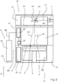
- FIG. 1 shows an overview of a system 1 for producing an object 2 by means of additive manufacturing.
- the system comprises an apparatus 19 that is built from several frame parts 11, 12, 13, 14.
- the apparatus 19 comprises a process chamber 3 for receiving a bath of material 4 which can be solidified.
- a shaft 50 is formed, wherein a support 5 is provided for positioning the object 2 in relation to the surface level L of the bath of material 4.
- the support 5 is movably provided in the shaft 50, such that after solidifying at least a part of a layer, the support 5 may be lowered, and a further layer of material may be solidified on top of the part of the object 2 already formed.
- a solidifying device 7 is provided for solidifying a selective part of the material.
- the solidifying device 7 is a laser device, which is arranged for producing electromagnetic radiation in the form of laser light, in order to melt a powdered material provided on the support, which then, after cooling forms a solidified part of the object 2 to be produced.
- the invention is not limited to the type of solidifying device 7.
- the electromagnetic radiation 71 emitted by the laser device 7 is deflected by means of a deflector unit 74, which uses a rotatable optical element 75 to direct the emitted radiation 71 towards the surface L of the layer of material 4.
- radiation may be emitted, as an example, according to rays 72, 73.
- powder supply means 6 are provided. These powder supply means 6 comprise a storage container 61 for storing powdered material that can be solidified. This storage container 61 is fluidly connected, via a powder supply means 16, such as a nozzle or a (rotary) valve, to the process chamber 3. Connected to the storage container 61 is a supply device 8.
- This movable supply device 8 has a supply container 18 for storing a supply of powdered material that can be solidified. As can be seen, the supply device 8 is fluidly connected to the storage container by means of line 86.
- the system 1 according to the invention is arranged for transferring powdered material between the supply container 18 and the apparatus 19, and in particular between the supply container 18 and the storage container 61.
- the transfer takes place from the supply container 18 to the storage container 61, and/or from the storage container 61 to the supply container 18.
- Transfer means such as fluid lines and one or more pumps, may be provided to this end.
- the supply device 8 is releasably connectable to the storage container 61. Suitable connecting means may be provided to this end, with which the supply device 8 may be connected and/or reconnected to the storage container 61.
- the supply device 8 is movable due to the fact that a number of wheel elements 19 are provided.
- the supply device it is relatively easy to refill the storage container 61, or to empty it if needed. Filling and/or emptying may be done relatively quickly, and may even be performed when the solidifying device 7 of the apparatus 19 is active. Filling of the supply device 8 may for instance be performed at a location distant from the apparatus 19, and may thus be performed under specific and controlled conditions, ensuring that the quality of the powdered material reaches a predetermined standard. The subsequent filling may then be performed relatively quickly.
- the supply device 8 is provided next to the apparatus 19, and connected by means of the connecting means 86 to the apparatus. Once said supply device 8 is connected to the apparatus 19, powdered material may be transferred between the supply container 18 and the apparatus 19.
- flushing means may be provided for flushing the connection means, in particular with an inert gas such as argon or nitrogen.
- a gas supply 117 may be present in the device 8 for flushing the connection means and conduits. Alternatively, the gas supply may be present in the apparatus 19 itself (not shown).
- the connection means may be flushed, in particular with an inert gas such as argon or nitrogen.
- an inert gas for flushing the lines and conduits increases the quality of the powder supply, as oxygen uptake by the powder will be prevented. Additionally, this increases the safety of the system, as the risk of explosion is dramatically reduced when oxygen is replaced by inert gases.
- the powdered material in the storage container 61 may be extracted to the supply container 18, where mixing takes place, whereafter the mixed powder may be transferred back to the storage container 61.
- the use of the storage device 8 allows the step of supplying powdered material to the storage container 61 to be performed during use of the solidifying device 7.
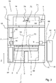
- Figure 2 shows a further embodiment of the system 1 with the apparatus 19.
- both storage containers 61, 62 are provided. Both storage containers 61, 62 are connected to the powder supply nozzle 16. Powder from both containers 61, 62 may thus be provided to the process chamber 3.
- the supply device 8 is connected, via lines 86 and 86', to both storage containers 61, 62. Powder may be supplied to both containers 61, 62, or may be extracted from both containers 61, 62. Alternatively, powder may be supplied to the top most container 62, and may be extracted from the bottom container 61.
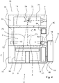
- Figure 3 shows a further embodiment of the system 1.
- the apparatus 19 shown further comprises an extraction device 9 fluidly connected to the process chamber 3 and arranged for extracting material 4 out of the process chamber.
- the extraction device 9 may be a pump.
- the supply device 8 is fluidly connected to the extraction device 9, and thus to the process chamber 3, by means of extraction line 89. Thus, when the extraction device 9 is activated, excess powder from the process chamber 3 may be transferred to the supply device 8 for further use.
- Figure 4 shows a further embodiment of the system 1.
- the apparatus 19 is provided with blowing means 10 on the opposite side of the process chamber 3 for inducing a gaseous flow in the process chamber 3 effecting the material to be extracted. Further blowing means may be provided as well, for more effectively influencing the powdered material in the process chamber 3.
- the blow nozzle 10 is connected via lines 82 to a control unit 94.
- the extraction device 9 is connected via line 84 to the control unit 94.
- the control unit 94 may be used to start and/or stop the blowing nozzle 10 (or nozzles).
- the extraction device 9, for instance in the form of a suction device 9, is also connected to this control unit 94, such that operation thereof may be synchronized. It is, however, conceivable that the extraction device 9 is provided with a separate control unit.
- Figure 4 further shows that the extraction device 9 is connected to the supply device 8 by means of extraction line 89.
- a storage container 61 is provided in the lower frame part 11 of the apparatus 19, and is also connected to the extraction device 9.
- the storage container 61 is also connected to the supply device 8.
- the storage container 61 is fluidly connected to the process chamber 3, such that a layer of material may be deposited in the process chamber 3. Details of this fluid connection are not shown in Figure 4 , but these details have already been described with reference to Figure 1 .
- FIG. 5 shows a further embodiment of the system 1 having two additional nozzles 92, 93, which may be movable nozzles 92, 93, and in which in particular details of the apparatus 19 downstream of the extraction device 9 are shown.
- the extraction device 9 comprises an extraction tube 121 comprising a pumping unit (shown as one unit 121), wherein an inlet opening of the extraction tube 121 is positioned within the process chamber 3.
- the extraction device 9 is fluidly connected, via line 87, to a filter unit 101, in particular a cyclone filter unit 101, which may be used to filter the extracted gaseous flow containing the material extracted from the process chamber. For instance, this allows powdered material contained in the flow to be filtered and collected for further usage.
- the cyclone filter unit 101 is connected, via line 111, to a first storage container 103 or collector, for collecting powdered material filtered by the filter unit 101.
- the gaseous flow may, after having passed the filter unit 101, be exhausted from the apparatus 19 by means of exhaust tube 114 and exhaust outlet 104. In this way, the gaseous flow may be vented through the exhaust tube 114 and outlet 104.
- the exhaust tube 114 is connected to the blowing means 10, such that the filtered gas flow may once again be introduced into the process chamber.
- the first storage container 103 is connected, via line 112, to a second storage container 102, provided above the first storage container 103. Material collected in the first storage container 103 may be transferred via line 112 to the second storage container 102, for later use.
- An overflow line 113 is provided between the second storage container 102 and the filter unit 101, which may be used to filter the extracted material a plurality of times, by re-feeding said material back to the filter unit a number of times, for instance.
- the extraction device 9 may be connected to one or more storage container 103, 102 for holding material extracted from the process chamber. This material may be re-used, for instance for laying down a further layer of material to be solidified.
- the system 1 comprises a supply device 8 that is connected to the first storage container 103 and the second storage container 102, via lines 86 and 88, respectively.
- the supply device 8 comprises a supply container 118, and a filter unit 119 provided upstream thereof.
- a pump unit (not shown) may be used to transfer powdered material from the supply device 118 to the first storage container 103. Additionally, or alternatively, powdered material may be extracted from the second storage container 102 to the supply container 118.
- the filter unit 119 may be used to further filter the powdered material coming from the second storage container 102.
Landscapes
- Chemical & Material Sciences (AREA)
- Engineering & Computer Science (AREA)
- Materials Engineering (AREA)
- Manufacturing & Machinery (AREA)
- Physics & Mathematics (AREA)
- Optics & Photonics (AREA)
- Mechanical Engineering (AREA)
- Life Sciences & Earth Sciences (AREA)
- Sustainable Development (AREA)
- Powder Metallurgy (AREA)
Description
- The present invention relates to a system for producing an object by means of additive manufacturing, comprising a process chamber for receiving a bath of material which can be solidified; a structure for positioning the object in relation to the surface level of the bath of material; a solidifying device for solidifying at least a part of a layer of the material on the surface.
- 3D printing or additive manufacturing refers to any of various processes for printing a three-dimensional object. Traditional techniques like injection molding can be less expensive for manufacturing, for example, polymer products in high quantities, but 3D printing or additive manufacturing can be faster, more flexible and less expensive when producing relatively small quantities of three-dimensional objects.
- It is anticipated that additive manufacturing becomes more and more important in the future, as the increasing competitive pressure forces companies to not only manufacture more economically with a constant high product quality but also to save time and costs in the area of product development. The life span of products is continuously shortened. In addition to product quality and product costs, the moment of market introduction is becoming increasingly important for the success of a product.
- The three-dimensional object may be produced by using a directed energy beam to selectively sinter a powder, or liquid material to produce a three-dimensional, 3D, object. In particular, a computer controlled additive manufacturing system may be used which sequentially sinters a plurality of layers to build the desired object in a layer-by-layer fashion. Primarily additive processes are used, in which successive layers of material are laid down under computer control. These objects can be of almost any shape or geometry, and are produced from a 3D model or other electronic data source.
- In order to print a three-dimensional object, a printable model is to be created with a computer design package or via a 3D scanner, for example. Usually, the input is a 3D CAD file such as an STL file, a STEP file or a IGS file. Before printing the object from a CAD file, the file is to be processed by a piece of software called a slicer, which converts the model into a series of thin subsequent layers. Further, system settings and vectors are generated for controlling the creation of each of the subsequent layers.
- A laser comprised in the computer controlled additive manufacturing system follows these settings and vectors to lay down successive layers of liquid, powder, paper or sheet material to build the 3D object from a series of cross sections. These layers, which correspond to the virtual cross sections from the CAD model, are then joined or fused to create the final 3D object.
- To reduce operational costs of the system, it is an object to fully utilize the capacity of the system and, at the same time, make sure that the total production lead time of a three dimensional object is minimized, i.e. the production queue is minimized.
- One of the challenges in the manufacturing of three dimensional objects, in particular in additive manufacturing of metal objects, is related to managing the quality of the layer to be solidified. The quality of the material to be solidified is of vital importance for obtaining desired product characteristics.
DE 102011088158 A1 discloses a secondary circuit for a device for manufacturing of three-dimensional objects.WO 95/34468 A1 claim 1 and a method using said apparatus. - It is therefore an object of the invention to provide a system and a method for producing an object by means of additive manufacturing, with which improved speed and accuracy of manufacturing may be obtained, in particular whilst at least maintaining or even increasing the quality of the material to be solidified.
- To this end, the invention provides a system according to
claim 1 and a method according toclaim 11. - The system according to the invention comprises an apparatus with a storage container for storing powdered material that can be solidified; with a process chamber fluidly connected to the storage container and arranged for receiving at least a part of the powdered material, preferably from said storage container, for forming a bath of material within the process chamber; with a structure for positioning the object in relation to the surface level of the bath of material; and with a solidifying device for solidifying at least a part of a layer of the bath of material.
- According to the invention, said system further comprises a supply device having a supply container for storing a supply of powdered material that can be solidified. Connection means are provided that fluidly connect, or are arranged for fluidly connecting, the supply device to the apparatus, preferably for fluidly connecting the supply container to the storage container. Additionally, transfer means are provided for transferring powdered material between the supply container and the apparatus, preferably for transferring powdered material between the supply container and the storage container.
- By using said system with a supply device for transferring powdered material from the supply container to the storage container, it becomes possible to quickly refill the storage container with a new supply of powdered material, for example. In addition, a high quality standard of the refilled supply may be ensured. In an embodiment, the supply container may be prefilled during use of the apparatus, and the system may be used to refill the storage container in an idle condition of the solidifying device. This not only ensures that a high quality supply may be provided in the supply container, but also means that the speed of manufacturing may be increased as the transfer of material from the supply container to the storage container may be performed relatively quickly. In an alternative embodiment, the apparatus may be provided with a new powder supply even during use of the apparatus, e.g. when using the apparatus for solidifying at least part of the layer of the bath of material. This decreases the idle time of the apparatus, and hence the productivity of the apparatus. Another advantage of using the supply device is that powdered material may be transferred from the apparatus back to the supply container. This way it is possible to remove a certain batch of powdered material from the apparatus, for example when it is detected that the quality of the powdered material does not reach a certain standard, or when a different material is needed for a next product.
- A further advantage of the supply device is that powder already present in the storage container may be mixed with a powder supply present in the supply container. In principle, this will be most easily be performed by extracting the powder from the storage container, and mixing with the powder supply in the supply container. After mixing, the mixed power may be supplied to the storage container. This mixing averages the quality of both powders, which counteracts the aging effect that naturally occurs when powdered material resides in the storage container. Thus, the supply device allows the quality of the used powdered material to be increased.
- Thus, from the above it follows that with the supply device according to the invention, the speed and accuracy of manufacturing, as well as the quality of the material to be solidified may be increased. With this, the object of the invention is achieved.
- Advantageous embodiments will be described below.
- In an embodiment, the system comprises flushing means for flushing the connection means, in particular with an inert gas such as argon or nitrogen. This increases the quality of the powder supply, as oxygen uptake by the powder will be prevented. Additionally, this increases the safety of the system, as the risk of explosion is dramatically reduced when oxygen is replaced by inert gases.
- The supply device is fluidly connectable to the storage container for supplying powdered material to the storage container, to be used for providing a layer of powdered material to the process chamber.
- It is beneficial if the storage container is arranged as an integral part of the apparatus. Within the context of the present disclosure an integral part is to be understood as a part that is designed as a part that remains inside the apparatus during a relative long period as opposed to consumable parts that are designed to be exchanged on a regular basis such as a build plate.
- The use of the supply device according to the invention allows a safe and controlled transfer of powdered material, in particular when, in a connected state of the supply device, the supply container and the process chamber are sealed from the environment. This means that in a connected state, a closed system for transferring powdered material from the supply device to the apparatus, and vice versa, is established. Powdered material is prevented from leaving this closed system.
- In an embodiment, the apparatus comprises an extraction device fluidly connected to the process chamber and arranged for extracting material out of the process chamber. With this, powdered material that remains in the process chamber after having solidified a layer of material, may be removed from the process chamber.
- The extraction device may further be fluidly connected, or at least connectable, to the supply device for transferring the extracted material to the supply device. This allows the powdered material to be directly transferred from the apparatus to the supply device.
- To enable an effective powder extraction, the apparatus comprises in an embodiment blowing means arranged for inducing a gaseous flow in the process chamber affecting the material to be extracted.
- The supply device is arranged to be releasably connectable to the storage container. This allows the supply device to be filled and/or emptied off site, i.e. at a location remote from the apparatus, where quality standards and/or conditions may be optimized.
- Transfer of material between the supply container and the storage container may be effected in an effective manner when the system comprises pneumatic transfer means for transferring the powdered material between the supply container and the storage container. As stated before, transferring may be from the supply container to the apparatus, for instance to the storage container, or from the apparatus (e.g. storage container) to the supply container, or vice versa, for instance due to the fact that a closed loop is formed between the apparatus and the supply container.
- In a cost effective embodiment, the pneumatic transfer means comprise at least a pump and fluid lines for connecting the storage container to the supply container. The pump may be provided in the apparatus itself, for instance in a frame unit thereof. Alternatively, the releasable supply device may comprise the pump, for forming an autonomous supply device.
- The system comprises a filter unit for filtering powdered material that is being transferred between the supply container and the apparatus. This further enhances the quality of the powdered material.
- In an effective embodiment, the filter unit comprises a cyclone filter. The filter unit, such as the cyclone filter, may be provided on the supply device. This way maintenance of the filter unit is relatively easy.
- According to an other aspect, the invention provides a method of supplying powdered material to an apparatus for producing an object by means of additive manufacturing according to
claim 11. - The method comprises the step of providing an apparatus having a storage container for storing powdered material that can be solidified; a process chamber fluidly connected to the storage container and arranged for receiving at least a part of the powdered material, preferably from the storage container, for forming a bath of material within the process chamber; a structure for positioning the object in relation to the surface level of the bath of material; and a solidifying device for solidifying at least a part of a layer of the bath of material.
- According to the invention, the method comprises the steps of providing a supply device having a supply container for storing a supply of powdered material that can be solidified. The method further comprises the step of connecting, by means of connecting means, in particular by means of mutually engaging connecting elements that are provided on the apparatus and the supply device, said supply device to the apparatus, preferably the storage container, and transferring powdered material between the supply container and the apparatus, preferably the storage container. Advantages of such a method have already been described in the foregoing.
- In an embodiment, said method comprises the step of flushing the connection means, in particular with an inert gas such as argon or nitrogen. In particular this step is performed before any transferring of powder takes place.
- In an embodiment, the method comprises the step of mixing powdered material in the storage container with powdered material in the supply container. By mixing, the quality of the powdered material in the storage container may be increased. Mixing may take place in the supply container. Hence, powdered material may be extracted from the storage container, be transferred to the supply container, and there be mixed with powdered material already present in the supply container. Afterwards, powdered material may be transferred back to the storage container.
- In an embodiment, the method comprises the step of supplying powdered material to the storage container during use of the solidifying device. This decreases the productivity of the apparatus, as the apparatus does not need to be idle for transferring powdered material to the apparatus. Additionally, or alternatively, the method may comprise the step of supplying powdered material to the storage container during non-use of the solidifying device.
- Embodiments of the invention will be described in the following in connection with the Figures. In the Figures:
-
Figure 1 shows a schematic overview of a first embodiment of a system according to the present disclosure for additive manufacturing an object; -
Figure 2 shows a schematic overview of a second embodiment of the system according to the present disclosure; -
Figure 3 shows a schematic overview of a third embodiment of the system according to the present disclosure; -
Figure 4 shows a schematic overview of a fourth embodiment of the system according to the present disclosure; -
Figure 5 shows a detailed overview of a fifth embodiment of the system according to the present disclosure. -
Figure 1 shows an overview of asystem 1 for producing anobject 2 by means of additive manufacturing. The system comprises anapparatus 19 that is built fromseveral frame parts apparatus 19 comprises aprocess chamber 3 for receiving a bath ofmaterial 4 which can be solidified. In alower frame part 11, ashaft 50 is formed, wherein asupport 5 is provided for positioning theobject 2 in relation to the surface level L of the bath ofmaterial 4. Thesupport 5 is movably provided in theshaft 50, such that after solidifying at least a part of a layer, thesupport 5 may be lowered, and a further layer of material may be solidified on top of the part of theobject 2 already formed. In atop part 13 of theapparatus 19, a solidifyingdevice 7 is provided for solidifying a selective part of the material. In the embodiment shown, the solidifyingdevice 7 is a laser device, which is arranged for producing electromagnetic radiation in the form of laser light, in order to melt a powdered material provided on the support, which then, after cooling forms a solidified part of theobject 2 to be produced. However, the invention is not limited to the type of solidifyingdevice 7. As can be seen, theelectromagnetic radiation 71 emitted by thelaser device 7 is deflected by means of adeflector unit 74, which uses a rotatableoptical element 75 to direct the emittedradiation 71 towards the surface L of the layer ofmaterial 4. Depending on the position of thedeflector unit 74, radiation may be emitted, as an example, according torays - On the left hand side of
Fig. 1 , powder supply means 6 are provided. These powder supply means 6 comprise astorage container 61 for storing powdered material that can be solidified. Thisstorage container 61 is fluidly connected, via a powder supply means 16, such as a nozzle or a (rotary) valve, to theprocess chamber 3. Connected to thestorage container 61 is asupply device 8. Thismovable supply device 8 has asupply container 18 for storing a supply of powdered material that can be solidified. As can be seen, thesupply device 8 is fluidly connected to the storage container by means ofline 86. Thesystem 1 according to the invention is arranged for transferring powdered material between thesupply container 18 and theapparatus 19, and in particular between thesupply container 18 and thestorage container 61. This may mean that the transfer takes place from thesupply container 18 to thestorage container 61, and/or from thestorage container 61 to thesupply container 18. Transfer means, such as fluid lines and one or more pumps, may be provided to this end. In the embodiment shown inFig. 1 , thesupply device 8 is releasably connectable to thestorage container 61. Suitable connecting means may be provided to this end, with which thesupply device 8 may be connected and/or reconnected to thestorage container 61. Thesupply device 8 is movable due to the fact that a number ofwheel elements 19 are provided. - With the supply device, it is relatively easy to refill the
storage container 61, or to empty it if needed. Filling and/or emptying may be done relatively quickly, and may even be performed when the solidifyingdevice 7 of theapparatus 19 is active. Filling of thesupply device 8 may for instance be performed at a location distant from theapparatus 19, and may thus be performed under specific and controlled conditions, ensuring that the quality of the powdered material reaches a predetermined standard. The subsequent filling may then be performed relatively quickly. - In an embodiment, the
supply device 8 is provided next to theapparatus 19, and connected by means of the connecting means 86 to the apparatus. Once saidsupply device 8 is connected to theapparatus 19, powdered material may be transferred between thesupply container 18 and theapparatus 19. - Additionally flushing means may be provided for flushing the connection means, in particular with an inert gas such as argon or nitrogen. A gas supply 117 (see
Fig. 5 ) may be present in thedevice 8 for flushing the connection means and conduits. Alternatively, the gas supply may be present in theapparatus 19 itself (not shown). Thus, the connection means may be flushed, in particular with an inert gas such as argon or nitrogen. In any event, the use of an inert gas for flushing the lines and conduits increases the quality of the powder supply, as oxygen uptake by the powder will be prevented. Additionally, this increases the safety of the system, as the risk of explosion is dramatically reduced when oxygen is replaced by inert gases. - Also, it will be possible to increase the quality of the powdered material in the
storage container 61 when the step is performed of mixing powdered material in thestorage container 61 with powdered material in thesupply container 18. To this end, the powdered material in thestorage container 61 may be extracted to thesupply container 18, where mixing takes place, whereafter the mixed powder may be transferred back to thestorage container 61. - As already stated, the use of the
storage device 8 allows the step of supplying powdered material to thestorage container 61 to be performed during use of the solidifyingdevice 7. -
Figure 2 shows a further embodiment of thesystem 1 with theapparatus 19. - In this embodiment two
storage containers storage containers powder supply nozzle 16. Powder from bothcontainers process chamber 3. Thesupply device 8 is connected, vialines 86 and 86', to bothstorage containers containers containers most container 62, and may be extracted from thebottom container 61. -
Figure 3 shows a further embodiment of thesystem 1. - In this embodiment, the
apparatus 19 shown further comprises anextraction device 9 fluidly connected to theprocess chamber 3 and arranged for extractingmaterial 4 out of the process chamber. Theextraction device 9 may be a pump. Thesupply device 8 is fluidly connected to theextraction device 9, and thus to theprocess chamber 3, by means ofextraction line 89. Thus, when theextraction device 9 is activated, excess powder from theprocess chamber 3 may be transferred to thesupply device 8 for further use. -
Figure 4 shows a further embodiment of thesystem 1. - This embodiment is similar to the embodiment of
Figure 3 , with the following additions. Here, theapparatus 19 is provided with blowing means 10 on the opposite side of theprocess chamber 3 for inducing a gaseous flow in theprocess chamber 3 effecting the material to be extracted. Further blowing means may be provided as well, for more effectively influencing the powdered material in theprocess chamber 3. Theblow nozzle 10 is connected vialines 82 to acontrol unit 94. Theextraction device 9 is connected vialine 84 to thecontrol unit 94. Thecontrol unit 94 may be used to start and/or stop the blowing nozzle 10 (or nozzles). Theextraction device 9, for instance in the form of asuction device 9, is also connected to thiscontrol unit 94, such that operation thereof may be synchronized. It is, however, conceivable that theextraction device 9 is provided with a separate control unit. -
Figure 4 further shows that theextraction device 9 is connected to thesupply device 8 by means ofextraction line 89. Astorage container 61 is provided in thelower frame part 11 of theapparatus 19, and is also connected to theextraction device 9. Thestorage container 61 is also connected to thesupply device 8. Thestorage container 61 is fluidly connected to theprocess chamber 3, such that a layer of material may be deposited in theprocess chamber 3. Details of this fluid connection are not shown inFigure 4 , but these details have already been described with reference toFigure 1 . -
Figure 5 shows a further embodiment of thesystem 1 having twoadditional nozzles movable nozzles apparatus 19 downstream of theextraction device 9 are shown. Theextraction device 9 comprises anextraction tube 121 comprising a pumping unit (shown as one unit 121), wherein an inlet opening of theextraction tube 121 is positioned within theprocess chamber 3. Furthermore, theextraction device 9 is fluidly connected, vialine 87, to afilter unit 101, in particular acyclone filter unit 101, which may be used to filter the extracted gaseous flow containing the material extracted from the process chamber. For instance, this allows powdered material contained in the flow to be filtered and collected for further usage. Thecyclone filter unit 101 is connected, vialine 111, to afirst storage container 103 or collector, for collecting powdered material filtered by thefilter unit 101. The gaseous flow may, after having passed thefilter unit 101, be exhausted from theapparatus 19 by means ofexhaust tube 114 andexhaust outlet 104. In this way, the gaseous flow may be vented through theexhaust tube 114 andoutlet 104. In a preferred embodiment, theexhaust tube 114 is connected to the blowing means 10, such that the filtered gas flow may once again be introduced into the process chamber. - The
first storage container 103 is connected, vialine 112, to asecond storage container 102, provided above thefirst storage container 103. Material collected in thefirst storage container 103 may be transferred vialine 112 to thesecond storage container 102, for later use. Anoverflow line 113 is provided between thesecond storage container 102 and thefilter unit 101, which may be used to filter the extracted material a plurality of times, by re-feeding said material back to the filter unit a number of times, for instance. - Thus, the
extraction device 9 may be connected to one ormore storage container - Furthermore, the
system 1 comprises asupply device 8 that is connected to thefirst storage container 103 and thesecond storage container 102, vialines supply device 8 comprises asupply container 118, and afilter unit 119 provided upstream thereof. A pump unit (not shown) may be used to transfer powdered material from thesupply device 118 to thefirst storage container 103. Additionally, or alternatively, powdered material may be extracted from thesecond storage container 102 to thesupply container 118. Thefilter unit 119 may be used to further filter the powdered material coming from thesecond storage container 102. - It will be clear to those skilled in the art, that the invention is described above by means of several embodiments. However, the invention is not limited to these embodiments. Combinations of individual parts of the several embodiments are conceivable. The desired protection is defined by the appended claims.
Claims (15)
- System (1) for producing an object (2) by means of additive manufacturing, comprising an apparatus (19) with:- a storage container (102, 103) for storing powdered material that can be solidified;- a process chamber (3) fluidly connected to the storage container (102, 103) and arranged for receiving at least a part of the powdered material from said storage container (102, 103) for forming a bath of material (4) within the process chamber (3);- a structure (5) for positioning the object (2) in relation to the surface level (L) of the bath of material (4); and- a solidifying device (7) for solidifying at least a part of a layer of the bath of material (4);wherein said system (1) further comprises:- a supply device (8) arranged for refilling the storage container (102, 103) with a new supply of powdered material, said supply device (8) having a supply container (118) for storing said new supply of powdered material that can be solidified and that can be supplied to the storage container ( 102, 103) wherein the supply device (8) is arranged to be releasably connectable to said apparatus (19);- connection means for fluidly connecting the supply container (118) to the storage container (102, 103); and- transfer means for transferring powdered material between the supply container (118) and the storage container (102, 103);characterized in that said system (1) comprises a filter unit (101, 119) for filtering powdered material that is being transferred between the supply container (118) and the apparatus (19).
- System (1) according to claim 1, further comprising flushing means for flushing the connection means, in particular with an inert gas such as argon or nitrogen.
- System (1) according to claim 1 or 2, wherein the storage container (102, 103) is arranged as an integral part of the apparatus (19).
- System (1) according to claim 1, 2 or 3, wherein, in a connected state of the supply device (8), the supply container (118) and the process chamber (3) are sealed from the environment.
- System (1) according to claim 1, 2, 3 or 4, wherein the apparatus (19) comprises an extraction device (9) fluidly connected to the process chamber (3) and arranged for extracting material out of the process chamber (3).
- System (1) according to claim 5, wherein the supply device (8) is fluidly connected, or at least connectable, to the extraction device (9) for transferring the extracted material to the supply device (8).
- System (1) according to any of the previous claims, wherein the transfer means comprise pneumatic transfer means.
- System (1) according to claim 7, wherein the pneumatic transfer means comprise at least a pump and fluid lines for connecting the supply container (18, 118) to the apparatus (19), preferably wherein the supply device (8) comprises said pump.
- System (1) according to any of the previous claims, wherein the filter unit (101) comprises a cyclone filter.
- System according to claim 9, wherein the supply device (8) comprises the filter unit (119).
- Method of supplying powdered material to an apparatus (19) for producing an object (2) by means of additive manufacturing, wherein said apparatus (19) comprises:- a storage container (102, 103) for storing powdered material that can be solidified;- a process chamber (3) fluidly connected to the storage container (102, 103) and arranged for receiving at least a part of the powdered material from the storage container (102, 103) for forming a bath of material (4) within the process chamber (3);- a structure (5) for positioning the object (2) in relation to the surface level (L) of the bath of material (4); and- a solidifying device (7) for solidifying at least a part of a layer of the bath of material (4);wherein said method comprises the steps of:- providing a supply device (8) arranged for refilling the storage container ( 102, 103) with a new supply of powdered material, said supply device (8) having a supply container (118) for storing a supply of powdered material that can be solidified and that can be supplied to the storage container ( 102, 103), wherein the supply device (8) is arranged to be releasably connectable to said apparatus (19);- providing a filter unit (101, 119) for filtering powdered material that is being transferred between the supply container (118) and the apparatus (19);- connecting, by means of connecting means, said supply container (118) to the storage container (102, 103), and- transferring powdered material between the supply container (118) and the storage container (102, 103),- filtering powdered material, by the filter unit (119), that is being transferred between the supply container (118) and the apparatus (19).
- Method according to claim 11, wherein said method comprises the step of flushing the connection means, in particular with an inert gas such as argon or nitrogen.
- Method according to claim 11 or 12, wherein the method comprises the step of mixing powdered material in the storage container (102, 103) with powdered material in the supply container (118).
- Method according to claims 11-13, wherein the method comprises the step of supplying powdered material to the storage container (102, 103) during use of the solidifying device (7).
- Method according to claims 11-14, wherein the method comprises the step of supplying powdered material to the storage container (102, 103) during non-use of the solidifying device (7).
Applications Claiming Priority (2)
| Application Number | Priority Date | Filing Date | Title |
|---|---|---|---|
| NL2017864A NL2017864B1 (en) | 2016-11-24 | 2016-11-24 | System for producing an object by means of additive manufacturing |
| PCT/NL2017/050727 WO2018097708A1 (en) | 2016-11-24 | 2017-11-10 | System for producing an object by means of additive manufacturing |
Publications (2)
| Publication Number | Publication Date |
|---|---|
| EP3544787A1 EP3544787A1 (en) | 2019-10-02 |
| EP3544787B1 true EP3544787B1 (en) | 2022-05-25 |
Family
ID=57460586
Family Applications (1)
| Application Number | Title | Priority Date | Filing Date |
|---|---|---|---|
| EP17817228.4A Active EP3544787B1 (en) | 2016-11-24 | 2017-11-10 | System and method for producing an object by means of additive manufacturing |
Country Status (6)
| Country | Link |
|---|---|
| US (1) | US11511487B2 (en) |
| EP (1) | EP3544787B1 (en) |
| JP (1) | JP7105764B2 (en) |
| CN (1) | CN110494271B (en) |
| NL (1) | NL2017864B1 (en) |
| WO (1) | WO2018097708A1 (en) |
Families Citing this family (4)
| Publication number | Priority date | Publication date | Assignee | Title |
|---|---|---|---|---|
| NL2017864B1 (en) | 2016-11-24 | 2018-06-01 | Additive Ind Bv | System for producing an object by means of additive manufacturing |
| EP3473360B1 (en) * | 2017-10-23 | 2022-08-10 | Renishaw PLC | Powder bed fusion apparatus |
| WO2020219031A1 (en) * | 2019-04-23 | 2020-10-29 | Hewlett-Packard Development Company, L.P. | Filter housing |
| CN112223747B (en) * | 2020-09-23 | 2022-10-04 | 浙江精功机器人智能装备有限公司 | Spread powder formula 3D printer |
Citations (7)
| Publication number | Priority date | Publication date | Assignee | Title |
|---|---|---|---|---|
| WO1995034468A1 (en) * | 1994-06-14 | 1995-12-21 | Soligen, Inc. | Powder handling apparatus for additive fabrication equipment |
| DE102011088158A1 (en) | 2011-12-09 | 2013-06-13 | Bayerische Motoren Werke Aktiengesellschaft | Secondary circuit for device for producing three-dimensional metal object used in beam fusion plant, has return line that is provided for recycling of powder from overflow container in main circuit of device |
| WO2013092757A1 (en) | 2011-12-20 | 2013-06-27 | Compagnie Generale Des Etablissements Michelin | Machine and process for powder-based additive manufacturing |
| WO2013178825A2 (en) | 2012-06-01 | 2013-12-05 | Compagnie Generale Des Etablissements Michelin | Machine and method for powder-based additive manufacturing |
| WO2016131785A1 (en) | 2015-02-16 | 2016-08-25 | Compagnie Generale Des Etablissements Michelin | Method for managing a powder in an additive manufacturing facility comprising a plurality of machines |
| EP3243620A1 (en) | 2016-05-09 | 2017-11-15 | Siemens Aktiengesellschaft | Additive manufacturing system |
| WO2018097708A1 (en) | 2016-11-24 | 2018-05-31 | Additive Industries B.V. | System for producing an object by means of additive manufacturing |
Family Cites Families (11)
| Publication number | Priority date | Publication date | Assignee | Title |
|---|---|---|---|---|
| US7296599B2 (en) * | 2005-03-31 | 2007-11-20 | 3D Systems, Inc. | Pneumatic powder transport system |
| GB2472783B (en) * | 2009-08-14 | 2012-05-23 | Norsk Titanium Components As | Device for manufacturing titanium objects |
| GB201204752D0 (en) * | 2012-03-19 | 2012-05-02 | Bae Systems Plc | Additive layer manufacturing |
| CN105188993A (en) * | 2013-03-15 | 2015-12-23 | 麦特法布公司 | Cartridge for an additive manufacturing apparatus and method |
| GB201316815D0 (en) * | 2013-09-23 | 2013-11-06 | Renishaw Plc | Additive manufacturing apparatus and method |
| CN110757796B (en) | 2014-11-24 | 2022-10-11 | 添加剂工业有限公司 | Apparatus and method for producing an article by additive manufacturing |
| EP3023227B1 (en) * | 2014-11-24 | 2018-01-03 | SLM Solutions Group AG | Powder circuit for use in an apparatus for producing three-dimensional work pieces |
| JP6019268B1 (en) * | 2015-11-13 | 2016-11-02 | 技術研究組合次世代3D積層造形技術総合開発機構 | Control method for three-dimensional additive manufacturing apparatus, control method for three-dimensional additive manufacturing apparatus, and control program for three-dimensional additive manufacturing apparatus |
| JP6798012B2 (en) * | 2016-10-27 | 2020-12-09 | ヒューレット−パッカード デベロップメント カンパニー エル.ピー.Hewlett‐Packard Development Company, L.P. | Entrance for construction material container |
| US20180339466A1 (en) * | 2017-05-26 | 2018-11-29 | Divergent Technologies, Inc. | Material handling in additive manufacturing |
| EP3473360B1 (en) * | 2017-10-23 | 2022-08-10 | Renishaw PLC | Powder bed fusion apparatus |
-
2016
- 2016-11-24 NL NL2017864A patent/NL2017864B1/en active
-
2017
- 2017-11-10 US US16/462,740 patent/US11511487B2/en active Active
- 2017-11-10 EP EP17817228.4A patent/EP3544787B1/en active Active
- 2017-11-10 CN CN201780081865.7A patent/CN110494271B/en active Active
- 2017-11-10 JP JP2019517053A patent/JP7105764B2/en active Active
- 2017-11-10 WO PCT/NL2017/050727 patent/WO2018097708A1/en unknown
Patent Citations (7)
| Publication number | Priority date | Publication date | Assignee | Title |
|---|---|---|---|---|
| WO1995034468A1 (en) * | 1994-06-14 | 1995-12-21 | Soligen, Inc. | Powder handling apparatus for additive fabrication equipment |
| DE102011088158A1 (en) | 2011-12-09 | 2013-06-13 | Bayerische Motoren Werke Aktiengesellschaft | Secondary circuit for device for producing three-dimensional metal object used in beam fusion plant, has return line that is provided for recycling of powder from overflow container in main circuit of device |
| WO2013092757A1 (en) | 2011-12-20 | 2013-06-27 | Compagnie Generale Des Etablissements Michelin | Machine and process for powder-based additive manufacturing |
| WO2013178825A2 (en) | 2012-06-01 | 2013-12-05 | Compagnie Generale Des Etablissements Michelin | Machine and method for powder-based additive manufacturing |
| WO2016131785A1 (en) | 2015-02-16 | 2016-08-25 | Compagnie Generale Des Etablissements Michelin | Method for managing a powder in an additive manufacturing facility comprising a plurality of machines |
| EP3243620A1 (en) | 2016-05-09 | 2017-11-15 | Siemens Aktiengesellschaft | Additive manufacturing system |
| WO2018097708A1 (en) | 2016-11-24 | 2018-05-31 | Additive Industries B.V. | System for producing an object by means of additive manufacturing |
Non-Patent Citations (2)
| Title |
|---|
| "SLM", 1 January 2014, SLM SOLUTIONS GMBH, article ANONYMOUS: "Betriebsanleitung Pulver Sieb Maschine Semi-Automatisch PSH 100", pages: 1 - 14, XP093029208 |
| ANONYMOUS: "Betriebsanleitung Selective Laser Melting-Anlage SLM®280HL", SLM SOLUTIONS GMBH, 1 January 2015 (2015-01-01), pages 1 - 16, XP093045437 |
Also Published As
| Publication number | Publication date |
|---|---|
| US11511487B2 (en) | 2022-11-29 |
| JP2020513340A (en) | 2020-05-14 |
| CN110494271B (en) | 2022-10-14 |
| EP3544787A1 (en) | 2019-10-02 |
| CN110494271A (en) | 2019-11-22 |
| WO2018097708A1 (en) | 2018-05-31 |
| JP7105764B2 (en) | 2022-07-25 |
| US20190375152A1 (en) | 2019-12-12 |
| NL2017864B1 (en) | 2018-06-01 |
Similar Documents
| Publication | Publication Date | Title |
|---|---|---|
| EP3544787B1 (en) | System and method for producing an object by means of additive manufacturing | |
| EP2359958B1 (en) | Method for production of a ceramic casting mold system | |
| CN109153176B (en) | Cooling of build material in three-dimensional printing systems | |
| EP2363221A2 (en) | Method and apparatus for production of a cast component | |
| US20120225210A1 (en) | Device and method for manufacturing a three-dimensional body | |
| JP2018524245A (en) | Powder conveying system and method for additional manufacturing equipment | |
| CN109070477B (en) | Cooling build material in 3D printing system | |
| CN104441656B (en) | Three-dimensional printer and its Method of printing | |
| JP6482006B2 (en) | 3D modeling equipment | |
| EP3612390B1 (en) | Three-dimensional printer | |
| CN204196268U (en) | Three-dimensional printer | |
| CN210211369U (en) | Melt and mix 3D printing system to particulate material | |
| US20220193781A1 (en) | Circulation paths for fluid dispensing devices | |
| CN204844876U (en) | Automatic 3D printer of clearance mesa | |
| NL2013860B1 (en) | Apparatus for producing an object by means of additive manufacturing. | |
| CN210139628U (en) | A melt and mix device for granular material 3D prints | |
| CN210139620U (en) | Printer for 3D printing | |
| WO2019094267A1 (en) | Powder refill system for an additive manufacturing machine | |
| CN204820357U (en) | Novel 3D printer | |
| CA2824923C (en) | Method and apparatus for production of a cast component | |
| BR102022011299A2 (en) | METHOD AND APPARATUS FOR MANUFACTURING 3D CERAMIC AND METALLIC OBJECTS THROUGH ADDITIVE MANUFACTURING | |
| CN109986774A (en) | A kind of 3D printer | |
| JP2019089283A (en) | Three-dimensional fabrication apparatus |
Legal Events
| Date | Code | Title | Description |
|---|---|---|---|
| STAA | Information on the status of an ep patent application or granted ep patent |
Free format text: STATUS: UNKNOWN |
|
| STAA | Information on the status of an ep patent application or granted ep patent |
Free format text: STATUS: THE INTERNATIONAL PUBLICATION HAS BEEN MADE |
|
| PUAI | Public reference made under article 153(3) epc to a published international application that has entered the european phase |
Free format text: ORIGINAL CODE: 0009012 |
|
| STAA | Information on the status of an ep patent application or granted ep patent |
Free format text: STATUS: REQUEST FOR EXAMINATION WAS MADE |
|
| 17P | Request for examination filed |
Effective date: 20190517 |
|
| AK | Designated contracting states |
Kind code of ref document: A1 Designated state(s): AL AT BE BG CH CY CZ DE DK EE ES FI FR GB GR HR HU IE IS IT LI LT LU LV MC MK MT NL NO PL PT RO RS SE SI SK SM TR |
|
| AX | Request for extension of the european patent |
Extension state: BA ME |
|
| DAV | Request for validation of the european patent (deleted) | ||
| DAX | Request for extension of the european patent (deleted) | ||
| STAA | Information on the status of an ep patent application or granted ep patent |
Free format text: STATUS: EXAMINATION IS IN PROGRESS |
|
| STAA | Information on the status of an ep patent application or granted ep patent |
Free format text: STATUS: EXAMINATION IS IN PROGRESS |
|
| 17Q | First examination report despatched |
Effective date: 20200917 |
|
| GRAP | Despatch of communication of intention to grant a patent |
Free format text: ORIGINAL CODE: EPIDOSNIGR1 |
|
| STAA | Information on the status of an ep patent application or granted ep patent |
Free format text: STATUS: GRANT OF PATENT IS INTENDED |
|
| GRAJ | Information related to disapproval of communication of intention to grant by the applicant or resumption of examination proceedings by the epo deleted |
Free format text: ORIGINAL CODE: EPIDOSDIGR1 |
|
| RIC1 | Information provided on ipc code assigned before grant |
Ipc: B33Y 40/00 20200101ALI20211029BHEP Ipc: B33Y 30/00 20150101ALI20211029BHEP Ipc: B33Y 10/00 20150101ALI20211029BHEP Ipc: B22F 12/00 20210101ALI20211029BHEP Ipc: B22F 10/20 20210101ALI20211029BHEP Ipc: B29C 64/20 20170101ALI20211029BHEP Ipc: B22F 3/105 20060101ALI20211029BHEP Ipc: B29C 64/357 20170101ALI20211029BHEP Ipc: B29C 64/321 20170101ALI20211029BHEP Ipc: B29C 64/153 20170101AFI20211029BHEP |
|
| STAA | Information on the status of an ep patent application or granted ep patent |
Free format text: STATUS: EXAMINATION IS IN PROGRESS |
|
| INTG | Intention to grant announced |
Effective date: 20211125 |
|
| INTC | Intention to grant announced (deleted) | ||
| GRAP | Despatch of communication of intention to grant a patent |
Free format text: ORIGINAL CODE: EPIDOSNIGR1 |
|
| STAA | Information on the status of an ep patent application or granted ep patent |
Free format text: STATUS: GRANT OF PATENT IS INTENDED |
|
| INTG | Intention to grant announced |
Effective date: 20220126 |
|
| GRAS | Grant fee paid |
Free format text: ORIGINAL CODE: EPIDOSNIGR3 |
|
| GRAA | (expected) grant |
Free format text: ORIGINAL CODE: 0009210 |
|
| STAA | Information on the status of an ep patent application or granted ep patent |
Free format text: STATUS: THE PATENT HAS BEEN GRANTED |
|
| AK | Designated contracting states |
Kind code of ref document: B1 Designated state(s): AL AT BE BG CH CY CZ DE DK EE ES FI FR GB GR HR HU IE IS IT LI LT LU LV MC MK MT NL NO PL PT RO RS SE SI SK SM TR |
|
| REG | Reference to a national code |
Ref country code: GB Ref legal event code: FG4D |
|
| REG | Reference to a national code |
Ref country code: CH Ref legal event code: EP |
|
| REG | Reference to a national code |
Ref country code: DE Ref legal event code: R096 Ref document number: 602017057858 Country of ref document: DE |
|
| REG | Reference to a national code |
Ref country code: AT Ref legal event code: REF Ref document number: 1494090 Country of ref document: AT Kind code of ref document: T Effective date: 20220615 |
|
| REG | Reference to a national code |
Ref country code: IE Ref legal event code: FG4D |
|
| REG | Reference to a national code |
Ref country code: LT Ref legal event code: MG9D |
|
| REG | Reference to a national code |
Ref country code: NL Ref legal event code: MP Effective date: 20220525 |
|
| REG | Reference to a national code |
Ref country code: AT Ref legal event code: MK05 Ref document number: 1494090 Country of ref document: AT Kind code of ref document: T Effective date: 20220525 |
|
| PG25 | Lapsed in a contracting state [announced via postgrant information from national office to epo] |
Ref country code: SE Free format text: LAPSE BECAUSE OF FAILURE TO SUBMIT A TRANSLATION OF THE DESCRIPTION OR TO PAY THE FEE WITHIN THE PRESCRIBED TIME-LIMIT Effective date: 20220525 Ref country code: PT Free format text: LAPSE BECAUSE OF FAILURE TO SUBMIT A TRANSLATION OF THE DESCRIPTION OR TO PAY THE FEE WITHIN THE PRESCRIBED TIME-LIMIT Effective date: 20220926 Ref country code: NO Free format text: LAPSE BECAUSE OF FAILURE TO SUBMIT A TRANSLATION OF THE DESCRIPTION OR TO PAY THE FEE WITHIN THE PRESCRIBED TIME-LIMIT Effective date: 20220825 Ref country code: NL Free format text: LAPSE BECAUSE OF FAILURE TO SUBMIT A TRANSLATION OF THE DESCRIPTION OR TO PAY THE FEE WITHIN THE PRESCRIBED TIME-LIMIT Effective date: 20220525 Ref country code: LT Free format text: LAPSE BECAUSE OF FAILURE TO SUBMIT A TRANSLATION OF THE DESCRIPTION OR TO PAY THE FEE WITHIN THE PRESCRIBED TIME-LIMIT Effective date: 20220525 Ref country code: HR Free format text: LAPSE BECAUSE OF FAILURE TO SUBMIT A TRANSLATION OF THE DESCRIPTION OR TO PAY THE FEE WITHIN THE PRESCRIBED TIME-LIMIT Effective date: 20220525 Ref country code: GR Free format text: LAPSE BECAUSE OF FAILURE TO SUBMIT A TRANSLATION OF THE DESCRIPTION OR TO PAY THE FEE WITHIN THE PRESCRIBED TIME-LIMIT Effective date: 20220826 Ref country code: FI Free format text: LAPSE BECAUSE OF FAILURE TO SUBMIT A TRANSLATION OF THE DESCRIPTION OR TO PAY THE FEE WITHIN THE PRESCRIBED TIME-LIMIT Effective date: 20220525 Ref country code: ES Free format text: LAPSE BECAUSE OF FAILURE TO SUBMIT A TRANSLATION OF THE DESCRIPTION OR TO PAY THE FEE WITHIN THE PRESCRIBED TIME-LIMIT Effective date: 20220525 Ref country code: BG Free format text: LAPSE BECAUSE OF FAILURE TO SUBMIT A TRANSLATION OF THE DESCRIPTION OR TO PAY THE FEE WITHIN THE PRESCRIBED TIME-LIMIT Effective date: 20220825 Ref country code: AT Free format text: LAPSE BECAUSE OF FAILURE TO SUBMIT A TRANSLATION OF THE DESCRIPTION OR TO PAY THE FEE WITHIN THE PRESCRIBED TIME-LIMIT Effective date: 20220525 |
|
| PG25 | Lapsed in a contracting state [announced via postgrant information from national office to epo] |
Ref country code: RS Free format text: LAPSE BECAUSE OF FAILURE TO SUBMIT A TRANSLATION OF THE DESCRIPTION OR TO PAY THE FEE WITHIN THE PRESCRIBED TIME-LIMIT Effective date: 20220525 Ref country code: PL Free format text: LAPSE BECAUSE OF FAILURE TO SUBMIT A TRANSLATION OF THE DESCRIPTION OR TO PAY THE FEE WITHIN THE PRESCRIBED TIME-LIMIT Effective date: 20220525 Ref country code: LV Free format text: LAPSE BECAUSE OF FAILURE TO SUBMIT A TRANSLATION OF THE DESCRIPTION OR TO PAY THE FEE WITHIN THE PRESCRIBED TIME-LIMIT Effective date: 20220525 Ref country code: IS Free format text: LAPSE BECAUSE OF FAILURE TO SUBMIT A TRANSLATION OF THE DESCRIPTION OR TO PAY THE FEE WITHIN THE PRESCRIBED TIME-LIMIT Effective date: 20220925 |
|
| PG25 | Lapsed in a contracting state [announced via postgrant information from national office to epo] |
Ref country code: SM Free format text: LAPSE BECAUSE OF FAILURE TO SUBMIT A TRANSLATION OF THE DESCRIPTION OR TO PAY THE FEE WITHIN THE PRESCRIBED TIME-LIMIT Effective date: 20220525 Ref country code: SK Free format text: LAPSE BECAUSE OF FAILURE TO SUBMIT A TRANSLATION OF THE DESCRIPTION OR TO PAY THE FEE WITHIN THE PRESCRIBED TIME-LIMIT Effective date: 20220525 Ref country code: RO Free format text: LAPSE BECAUSE OF FAILURE TO SUBMIT A TRANSLATION OF THE DESCRIPTION OR TO PAY THE FEE WITHIN THE PRESCRIBED TIME-LIMIT Effective date: 20220525 Ref country code: EE Free format text: LAPSE BECAUSE OF FAILURE TO SUBMIT A TRANSLATION OF THE DESCRIPTION OR TO PAY THE FEE WITHIN THE PRESCRIBED TIME-LIMIT Effective date: 20220525 Ref country code: DK Free format text: LAPSE BECAUSE OF FAILURE TO SUBMIT A TRANSLATION OF THE DESCRIPTION OR TO PAY THE FEE WITHIN THE PRESCRIBED TIME-LIMIT Effective date: 20220525 Ref country code: CZ Free format text: LAPSE BECAUSE OF FAILURE TO SUBMIT A TRANSLATION OF THE DESCRIPTION OR TO PAY THE FEE WITHIN THE PRESCRIBED TIME-LIMIT Effective date: 20220525 |
|
| REG | Reference to a national code |
Ref country code: DE Ref legal event code: R026 Ref document number: 602017057858 Country of ref document: DE |
|
| PLBI | Opposition filed |
Free format text: ORIGINAL CODE: 0009260 |
|
| PLAX | Notice of opposition and request to file observation + time limit sent |
Free format text: ORIGINAL CODE: EPIDOSNOBS2 |
|
| 26 | Opposition filed |
Opponent name: SLM SOLUTIONS GROUP AG Effective date: 20230221 |
|
| PG25 | Lapsed in a contracting state [announced via postgrant information from national office to epo] |
Ref country code: AL Free format text: LAPSE BECAUSE OF FAILURE TO SUBMIT A TRANSLATION OF THE DESCRIPTION OR TO PAY THE FEE WITHIN THE PRESCRIBED TIME-LIMIT Effective date: 20220525 |
|
| PG25 | Lapsed in a contracting state [announced via postgrant information from national office to epo] |
Ref country code: SI Free format text: LAPSE BECAUSE OF FAILURE TO SUBMIT A TRANSLATION OF THE DESCRIPTION OR TO PAY THE FEE WITHIN THE PRESCRIBED TIME-LIMIT Effective date: 20220525 |
|
| PG25 | Lapsed in a contracting state [announced via postgrant information from national office to epo] |
Ref country code: MC Free format text: LAPSE BECAUSE OF FAILURE TO SUBMIT A TRANSLATION OF THE DESCRIPTION OR TO PAY THE FEE WITHIN THE PRESCRIBED TIME-LIMIT Effective date: 20220525 |
|
| REG | Reference to a national code |
Ref country code: CH Ref legal event code: PL |
|
| PLBB | Reply of patent proprietor to notice(s) of opposition received |
Free format text: ORIGINAL CODE: EPIDOSNOBS3 |
|
| P01 | Opt-out of the competence of the unified patent court (upc) registered |
Effective date: 20230527 |
|
| PG25 | Lapsed in a contracting state [announced via postgrant information from national office to epo] |
Ref country code: LI Free format text: LAPSE BECAUSE OF NON-PAYMENT OF DUE FEES Effective date: 20221130 Ref country code: CH Free format text: LAPSE BECAUSE OF NON-PAYMENT OF DUE FEES Effective date: 20221130 |
|
| PG25 | Lapsed in a contracting state [announced via postgrant information from national office to epo] |
Ref country code: LU Free format text: LAPSE BECAUSE OF NON-PAYMENT OF DUE FEES Effective date: 20221110 |
|
| PLAB | Opposition data, opponent's data or that of the opponent's representative modified |
Free format text: ORIGINAL CODE: 0009299OPPO |
|
| PG25 | Lapsed in a contracting state [announced via postgrant information from national office to epo] |
Ref country code: IE Free format text: LAPSE BECAUSE OF NON-PAYMENT OF DUE FEES Effective date: 20221110 |
|
| R26 | Opposition filed (corrected) |
Opponent name: NIKON SLM SOLUTIONS AG Effective date: 20230221 |
|
| PGFP | Annual fee paid to national office [announced via postgrant information from national office to epo] |
Ref country code: GB Payment date: 20231123 Year of fee payment: 7 |
|
| PGFP | Annual fee paid to national office [announced via postgrant information from national office to epo] |
Ref country code: IT Payment date: 20231124 Year of fee payment: 7 Ref country code: FR Payment date: 20231120 Year of fee payment: 7 Ref country code: DE Payment date: 20231121 Year of fee payment: 7 |
|
| PGFP | Annual fee paid to national office [announced via postgrant information from national office to epo] |
Ref country code: BE Payment date: 20231120 Year of fee payment: 7 |
|
| PG25 | Lapsed in a contracting state [announced via postgrant information from national office to epo] |
Ref country code: HU Free format text: LAPSE BECAUSE OF FAILURE TO SUBMIT A TRANSLATION OF THE DESCRIPTION OR TO PAY THE FEE WITHIN THE PRESCRIBED TIME-LIMIT; INVALID AB INITIO Effective date: 20171110 |
|
| PG25 | Lapsed in a contracting state [announced via postgrant information from national office to epo] |
Ref country code: CY Free format text: LAPSE BECAUSE OF FAILURE TO SUBMIT A TRANSLATION OF THE DESCRIPTION OR TO PAY THE FEE WITHIN THE PRESCRIBED TIME-LIMIT Effective date: 20220525 |