EP3540294A1 - Motor vehicle light module - Google Patents
Motor vehicle light module Download PDFInfo
- Publication number
- EP3540294A1 EP3540294A1 EP18161982.6A EP18161982A EP3540294A1 EP 3540294 A1 EP3540294 A1 EP 3540294A1 EP 18161982 A EP18161982 A EP 18161982A EP 3540294 A1 EP3540294 A1 EP 3540294A1
- Authority
- EP
- European Patent Office
- Prior art keywords
- light
- motor vehicle
- micro
- light module
- projection system
- Prior art date
- Legal status (The legal status is an assumption and is not a legal conclusion. Google has not performed a legal analysis and makes no representation as to the accuracy of the status listed.)
- Withdrawn
Links
Images

Classifications
-
- F—MECHANICAL ENGINEERING; LIGHTING; HEATING; WEAPONS; BLASTING
- F21—LIGHTING
- F21S—NON-PORTABLE LIGHTING DEVICES; SYSTEMS THEREOF; VEHICLE LIGHTING DEVICES SPECIALLY ADAPTED FOR VEHICLE EXTERIORS
- F21S41/00—Illuminating devices specially adapted for vehicle exteriors, e.g. headlamps
- F21S41/10—Illuminating devices specially adapted for vehicle exteriors, e.g. headlamps characterised by the light source
- F21S41/14—Illuminating devices specially adapted for vehicle exteriors, e.g. headlamps characterised by the light source characterised by the type of light source
- F21S41/141—Light emitting diodes [LED]
- F21S41/143—Light emitting diodes [LED] the main emission direction of the LED being parallel to the optical axis of the illuminating device
-
- B—PERFORMING OPERATIONS; TRANSPORTING
- B60—VEHICLES IN GENERAL
- B60Q—ARRANGEMENT OF SIGNALLING OR LIGHTING DEVICES, THE MOUNTING OR SUPPORTING THEREOF OR CIRCUITS THEREFOR, FOR VEHICLES IN GENERAL
- B60Q1/00—Arrangement of optical signalling or lighting devices, the mounting or supporting thereof or circuits therefor
- B60Q1/02—Arrangement of optical signalling or lighting devices, the mounting or supporting thereof or circuits therefor the devices being primarily intended to illuminate the way ahead or to illuminate other areas of way or environments
- B60Q1/24—Arrangement of optical signalling or lighting devices, the mounting or supporting thereof or circuits therefor the devices being primarily intended to illuminate the way ahead or to illuminate other areas of way or environments for lighting other areas than only the way ahead
-
- B—PERFORMING OPERATIONS; TRANSPORTING
- B60—VEHICLES IN GENERAL
- B60Q—ARRANGEMENT OF SIGNALLING OR LIGHTING DEVICES, THE MOUNTING OR SUPPORTING THEREOF OR CIRCUITS THEREFOR, FOR VEHICLES IN GENERAL
- B60Q3/00—Arrangement of lighting devices for vehicle interiors; Lighting devices specially adapted for vehicle interiors
- B60Q3/60—Arrangement of lighting devices for vehicle interiors; Lighting devices specially adapted for vehicle interiors characterised by optical aspects
-
- F—MECHANICAL ENGINEERING; LIGHTING; HEATING; WEAPONS; BLASTING
- F21—LIGHTING
- F21S—NON-PORTABLE LIGHTING DEVICES; SYSTEMS THEREOF; VEHICLE LIGHTING DEVICES SPECIALLY ADAPTED FOR VEHICLE EXTERIORS
- F21S41/00—Illuminating devices specially adapted for vehicle exteriors, e.g. headlamps
- F21S41/10—Illuminating devices specially adapted for vehicle exteriors, e.g. headlamps characterised by the light source
- F21S41/12—Illuminating devices specially adapted for vehicle exteriors, e.g. headlamps characterised by the light source characterised by the type of emitted light
- F21S41/125—Coloured light
-
- F—MECHANICAL ENGINEERING; LIGHTING; HEATING; WEAPONS; BLASTING
- F21—LIGHTING
- F21S—NON-PORTABLE LIGHTING DEVICES; SYSTEMS THEREOF; VEHICLE LIGHTING DEVICES SPECIALLY ADAPTED FOR VEHICLE EXTERIORS
- F21S41/00—Illuminating devices specially adapted for vehicle exteriors, e.g. headlamps
- F21S41/10—Illuminating devices specially adapted for vehicle exteriors, e.g. headlamps characterised by the light source
- F21S41/14—Illuminating devices specially adapted for vehicle exteriors, e.g. headlamps characterised by the light source characterised by the type of light source
- F21S41/141—Light emitting diodes [LED]
-
- F—MECHANICAL ENGINEERING; LIGHTING; HEATING; WEAPONS; BLASTING
- F21—LIGHTING
- F21S—NON-PORTABLE LIGHTING DEVICES; SYSTEMS THEREOF; VEHICLE LIGHTING DEVICES SPECIALLY ADAPTED FOR VEHICLE EXTERIORS
- F21S41/00—Illuminating devices specially adapted for vehicle exteriors, e.g. headlamps
- F21S41/20—Illuminating devices specially adapted for vehicle exteriors, e.g. headlamps characterised by refractors, transparent cover plates, light guides or filters
- F21S41/25—Projection lenses
- F21S41/265—Composite lenses; Lenses with a patch-like shape
-
- B—PERFORMING OPERATIONS; TRANSPORTING
- B60—VEHICLES IN GENERAL
- B60Q—ARRANGEMENT OF SIGNALLING OR LIGHTING DEVICES, THE MOUNTING OR SUPPORTING THEREOF OR CIRCUITS THEREFOR, FOR VEHICLES IN GENERAL
- B60Q2400/00—Special features or arrangements of exterior signal lamps for vehicles
- B60Q2400/50—Projected symbol or information, e.g. onto the road or car body
-
- B—PERFORMING OPERATIONS; TRANSPORTING
- B60—VEHICLES IN GENERAL
- B60Q—ARRANGEMENT OF SIGNALLING OR LIGHTING DEVICES, THE MOUNTING OR SUPPORTING THEREOF OR CIRCUITS THEREFOR, FOR VEHICLES IN GENERAL
- B60Q2900/00—Features of lamps not covered by other groups in B60Q
- B60Q2900/30—Lamps commanded by wireless transmissions
-
- B—PERFORMING OPERATIONS; TRANSPORTING
- B60—VEHICLES IN GENERAL
- B60Q—ARRANGEMENT OF SIGNALLING OR LIGHTING DEVICES, THE MOUNTING OR SUPPORTING THEREOF OR CIRCUITS THEREFOR, FOR VEHICLES IN GENERAL
- B60Q3/00—Arrangement of lighting devices for vehicle interiors; Lighting devices specially adapted for vehicle interiors
- B60Q3/20—Arrangement of lighting devices for vehicle interiors; Lighting devices specially adapted for vehicle interiors for lighting specific fittings of passenger or driving compartments; mounted on specific fittings of passenger or driving compartments
-
- F—MECHANICAL ENGINEERING; LIGHTING; HEATING; WEAPONS; BLASTING
- F21—LIGHTING
- F21W—INDEXING SCHEME ASSOCIATED WITH SUBCLASSES F21K, F21L, F21S and F21V, RELATING TO USES OR APPLICATIONS OF LIGHTING DEVICES OR SYSTEMS
- F21W2102/00—Exterior vehicle lighting devices for illuminating purposes
-
- F—MECHANICAL ENGINEERING; LIGHTING; HEATING; WEAPONS; BLASTING
- F21—LIGHTING
- F21W—INDEXING SCHEME ASSOCIATED WITH SUBCLASSES F21K, F21L, F21S and F21V, RELATING TO USES OR APPLICATIONS OF LIGHTING DEVICES OR SYSTEMS
- F21W2103/00—Exterior vehicle lighting devices for signalling purposes
- F21W2103/60—Projection of signs from lighting devices, e.g. symbols or information being projected onto the road
-
- F—MECHANICAL ENGINEERING; LIGHTING; HEATING; WEAPONS; BLASTING
- F21—LIGHTING
- F21W—INDEXING SCHEME ASSOCIATED WITH SUBCLASSES F21K, F21L, F21S and F21V, RELATING TO USES OR APPLICATIONS OF LIGHTING DEVICES OR SYSTEMS
- F21W2107/00—Use or application of lighting devices on or in particular types of vehicles
- F21W2107/10—Use or application of lighting devices on or in particular types of vehicles for land vehicles
-
- F—MECHANICAL ENGINEERING; LIGHTING; HEATING; WEAPONS; BLASTING
- F21—LIGHTING
- F21Y—INDEXING SCHEME ASSOCIATED WITH SUBCLASSES F21K, F21L, F21S and F21V, RELATING TO THE FORM OR THE KIND OF THE LIGHT SOURCES OR OF THE COLOUR OF THE LIGHT EMITTED
- F21Y2115/00—Light-generating elements of semiconductor light sources
- F21Y2115/10—Light-emitting diodes [LED]
Definitions
- the invention relates to a motor vehicle light module comprising a light means arranged for generating preferably collimated light, a projection system downstream of the light source which projects the light generated by the light source into an area in front of the motor vehicle light module, the projection system comprising a support of a material that can be transmitted through light, a micro-light.
- Exit optics array and an aperture device
- the aperture device is disposed on a side facing the lamp of the carrier and the micro-exit optical array close to a side facing away from the lamp, the diaphragm device having a plurality of diaphragm areas, each Aperture region is associated with at least one micro-exit optics of the micro-exit optical array and each aperture region and at least one, this aperture range associated micro-exit optics form a partial projection system, each sub-projection system e is associated in the illuminant area of the luminous means in such a way that the preferably collimated light generated by this illuminant area substantially only strikes that partial projection system to which this illuminant area is assigned.
- the invention relates to a lighting system for a motor vehicle comprising at least one above-mentioned motor vehicle light module.
- the invention relates to a motor vehicle headlight with at least one above-mentioned motor vehicle light module or a lighting system mentioned above.
- the invention relates to a motor vehicle with at least one motor vehicle light module, wherein the motor vehicle light module is installed in the interior of the motor vehicle.
- Automotive light modules of the above type are known in the art (see, for example DE 102015220911 A1 . DE 102015115242 A1 ). Such motor vehicle light modules have the disadvantage that they are static. That is, the number of possible light patterns is quite limited.
- the object of the present invention is to provide a motor vehicle light module in which, firstly, the number of possible light patterns is increased and, secondly, dynamic (eg real-time playable) light patterns are possible.
- the partial projection systems are designed differently and the light-emitting means are controlled independently of each other by means of a control device, each partial projection system from the light source area radiated light in the form of a (for example, in color, brightness, etc.) controllable partial light pattern projected into an area in front of the motor vehicle light module and the controllable partial light patterns together form a controllable light pattern.
- a control device for example, in color, brightness, etc.
- the object is also achieved with a lighting system of the type mentioned above, which comprises the control device.
- controllable light pattern can be influenced both by the control device (for example switching on and off the partial light pattern) and by design of the diaphragm areas (shape and position of the diaphragm edges in diaphragm areas, etc.).
- the lighting means may be, for example, an LED light source.
- the LED light source may be an optical element, such as an optic, for example a TIR optic or a silicone optic body, downstream, which optics or which silicone optic body collimates the light emitted by the LED light source.
- the lighting means may also be a light conversion means.
- the light conversion means may also be followed by an optical element of the abovementioned type which collimates the mostly diffused light generated by the light conversion means.
- micro-exit optical array an array of micro-optics, preferably microlenses (characteristic size is preferably in the micrometer range), which are arranged in a matrix-like array in a plane transverse to the optical axis of the motor vehicle light module.
- micro exit optics arrays are for example in the applications WO 2015/058227 A1 .
- WO 2017/066817 A1 and WO 2017/066818 A1 the applicant described in detail.
- the micro-exit optical array can be fixedly connected to the carrier, which is formed for example as a glass substrate.
- the carrier may thus be connected to both the diaphragm device and the micro-exit optical array.
- an optical thickness of the entire projection system and consequently its optical parameters, such as cutting width can be changed more easily.
- the beam path of the light of the illuminant passes through both materials - carrier and micro exit optics array.
- the material of the carrier for example glass, takes over part of the lens body of the micro exit optics of the micro exit optics array.
- the amount of material that is required for the production of the micro-exit optical array can be reduced.
- the diaphragm device is exchangeable.
- corresponding adjustment and fixing means may be provided in the motor vehicle light module, which allow the projection system to be positioned with respect to the illuminant, adjusted and fixed after the adjustment.
- the adjusting and fixing means can be designed such that the projection system or diaphragm device can be easily replaced.
- similar mechanisms can be used as with a slide projector.
- the corresponding projection system or the diaphragm device of the corresponding projection system in the present invention projection system similar to slides in a slide projector to be interchangeable.
- the user-friendliness of the motor vehicle light module can be increased by the user acquiring, for example, the projection systems or their diaphragm device with differently designed diaphragm devices, exchanging them as needed and in this way achieving a desired illumination pattern.
- the diaphragm areas of the different partial projection systems are designed differently.
- the diaphragm areas of an aperture device may be arranged in a 4x5 array.
- the aperture devices in the present invention can reach sizes of about 7.2x10mm.
- the micro-exit optical array is formed as a small plate, wherein the plate in about 1 to 10 mm wide and 1 to 10 mm long, preferably 1 to 2 mm wide and 2 to 3 mm long , in particular 1.8 mm by 2 mm in size.
- micro-exit optics are arranged in the micro-exit optical array in a regular, for example in a square or hexagonal pattern and preferably formed as convex lenses, wherein the lenses have a characteristic size, for example a characteristic diameter of their The lamp-facing side, in the micrometer range.
- the area utilization (for example, of the carrier) can be improved.
- control device may comprise a control device with an internal storage medium, wherein software is stored in the control device, which software is configured to control the individual light-emitting device regions.
- control unit is portable, preferably designed as a smartphone or a tablet
- software is designed as an application software, preferably a smartphone or tablet app.
- the luminous means is designed as an LED light source comprising a plurality of individual LEDs, with each illuminant area preferably comprising at least one LED.
- each LED is a lichtkollimierender optical body, such as a TIR lens or a silicone-optic body, downstream.
- a lichtkollimierender optical body such as a TIR lens or a silicone-optic body
- the projection system further comprises a micro-entrance optical array, which is upstream of the carrier, that each micro-exit optics is associated with at least one micro-entry optics of the micro-entry optics array ,
- illuminant regions provision can be made for different illuminant regions to be set up to emit light in respectively different wavelengths.
- Another field of application is ambient or contour lighting in vehicles.
- control device which software is configured to control the individual illuminant areas, and the control device is either an integral part of the motor vehicle light module or a motor vehicle light module. external control device is.
- the software of the control device by means of a portable controller is remote-controlled, wherein the portable control device is preferably designed as a smartphone or a tablet, and the software is designed as an application software.
- the lighting system is installed in a motor vehicle headlight.
- control device may be, for example, a motor vehicle on-board computer.
- vehicle light module in a Motor vehicle headlight or be installed, for example, in the interior of a motor vehicle.
- FIGS. 1 and 2 show a schematic structure of a lighting system for a motor vehicle with a light module 1, which light module 1 can be installed both in a motor vehicle headlight and for example in the interior of a motor vehicle, and a control device 6.
- the control device can be both an integral part of the light module 1 as also assigned to the light module 1 externally and be designed for example as a motor vehicle on-board computer.
- the light module 1 can correspond to a motor vehicle light module according to the invention.
- the light module 1 has a luminous means 2 and a projection system 4 downstream of the luminous means 2.
- the luminous means 2 is set up, preferably designed such that it generates light 3 in an activated state.
- light-collimating optical elements may be arranged in front of the light source 2. These optical elements are not necessary and serve for improved coupling of the lamp 2 radiated light 3 in the projection system 4. The coupling can also be achieved by reducing the distance between the light emitting means 2 and the projection system 4.
- the light 3 for example in the form of a predetermined controllable light pattern, in particular a desired logo or an arrow, in an area 5 in front of the light module 1, for example in the traffic area, in particular on the road surface, when the light module in a Motor vehicle is put into operation, shown.
- the area 5 can also be inside the motor vehicle when the light module 1 is installed in the interior of the motor vehicle.
- the projection system 4 comprises a carrier 40 made of a material which can be irradiated by the collimated light 3, for example, a micro exit optics array 41 and a diaphragm device 42.
- the diaphragm device 42 is arranged on a side of the carrier 40 facing the light source 2.
- the micro-exit optical array 41 is close, so that, for example, an air gap of 0 to 10 mm is present, or it is arranged directly on a side of the carrier 40 facing away from the luminous means 2. In this case, the air gap should be such that the entire light 3 penetrated by the carrier 40 strikes the micro exit optics array 41 and preferably almost no scattered light and / or light losses occur / arise.
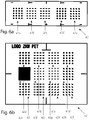
- the diaphragm device 42 has a plurality of diaphragm areas 42a to 42l (see also FIGS Figures 6a and 6b ), wherein each aperture region 42a to 42l corresponds to at least one micro exit optics 41a to 41d of the micro exit optics array 41, each aperture region 42a to 42l and at least one micro exit optic corresponding to this aperture region 42a to 42l 41a to 41d form a partial projection system.
- each partial projection system is assigned a light source region 2a to 2d of the light source 2 in such a way that the light 3a to 3d produced by this light source region 2a to 3d, for example, collides essentially only with the partial projection system to which this light source Area 2a is assigned to 2d.
- the light source 2 of the light module 1 of FIG. 2 is designed such that its different light emitting regions 2a to 2d can emit light in different colors, wavelengths.
- Both the carrier 40 and the micro-exit optical array 41 may be made of various materials, such as UV-acrylate, silicone, glass or plastic. Glass supports - glass supports - have become reality proven.
- the micro-exit optical array 41 may for example be attached directly to the carrier 40, in particular glued to it.
- the number of lamp areas 2a to 2d of the number of partial projection systems is preferably the same. It can also be provided that exactly one micro exit optics 41a to 41d corresponds to each aperture area 42a to 42l.
- the number of lamp areas 2a to 2d, as well as the number of partial projection systems vary. It can be 1 to 20 or 30, depending on the desired light output of the system.
- the number of partial projection systems for example, is related to the luminous efficiency, since the amount of light / area depends on the respective luminous means, which may be formed, for example, as an LED light source with an upstream collimator element.
- a collimator element may, for example, comprise one or more collimating attachment optics or optic bodies, such as TIR lenses, or one or more collimating reflectors (hollow optic bodies). For applications that require little light, even a single partial projection system can be enough.
- FIG. 6a shows, for example, five in a row arranged aperture areas 42a to 42e.
- FIG. 6b shows, for example, twelve aperture areas 42a to 42l arranged in a 3x4 matrix.
- the partial projection systems are designed differently. In view of the above, it is said that different controllable partial light patterns can be generated by using different partial projection systems.
- the partial light patterns together form the controllable light pattern.
- the above-mentioned control device 6 is arranged to control the illuminant regions 2a to 2d independently of each other. As a result, the number of variations of the emitted light pattern is significantly increased. Thus, certain individual light-emitting means regions 2a to 2d can be dimmed or even switched off or illuminated by means of the control device 6, as a result of which the one partial light pattern no longer arises, but the others do. So it is e.g. possible to switch between different logos or other characters or combine them as you wish.
- the entire projection system 4 or only its diaphragm device 42 is exchangeable. Which results in even more creative freedom.
- a customer can thus a projection system or their Acquire and replace the bezel assembly with the desired symbols.
- the individual personalization can be significantly extended without increasing the basic structure of the system.
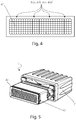
- the micro exit optics array 41 may be formed as a die. Which platelet is about 1 to 10 mm wide and 1 to 10 mm long, preferably 1 to 2 mm wide and 2 to 3 mm long. In particular, a micro-exit optics can be 1.8 mm by 2 mm in size. From this micro exit optics arrays 41 of different sizes, for example 10x10mm but also 36x55mm, can be formed. In this case, the platelet, as the figures undoubtedly can be seen, is arranged in a plane perpendicular to a main emission direction of the light module.
- the micro exit optics 41a to 41d in the micro exit optics array 41 in a regular, for example in a square (see FIG. 4 ) or hexagonal (not shown) patterns.
- the micro-exit optics may be formed as convex lenses having a characteristic size, for example, diameter of their side facing the lamp 2, in the micrometer range. In this case, a very advantageous overall depth of the entire light module is achieved. By using such small optics located in the micro exit optics array, the light output can be increased and adjusted for the particular application.
- control device which software is configured to control the individual light-emitting means regions 2a to 2d.
- control device which software is configured to control the individual light-emitting means regions 2a to 2d.
- the software is designed as an application software.
- the software of the control device by means of a portable controller is remote controlled.
- the controller may be a smartphone or a tablet with a corresponding, connectable with the software smartphone or tablet app.
- the number of users who can operate the lighting system or the light module is increased dramatically.
- Another advantage results from the fact that the desired light pattern not directly to the lighting system or to the light module but away from the Light module on the portable control unit, simulated and set and can be played later on the lighting system or on the light module only.
- the luminous means 2 is designed as an LED light source comprising a plurality of individual LEDs, wherein preferably each luminous means region 2a to 2d comprises at least one LED.
- the LEDs can be applied to a common board 20 in a matrix-like arrangement, wherein each light-collimating optical body 21 is preferably downstream of each individual LED.
- the light-collimating optical body 21 is also called a "collimator”.
- Lich collimating optics body or collimator subsumes several terms, such as TIR lens, silicone optic body, light-guiding silicone optics or a reflector with mirrored reflector surfaces of a certain shape.
- all light-collimating optical body 21 can be formed integrally with each other.
- One-piece designs are easier to manufacture.
- the light-collimating optical bodies 21 (regardless of whether they are integrally formed with each other or separately) may be fixed to the common board 20 / fixed.
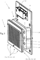
- FIG. 3 an arranged on the common board 20 interface 6b for - in this case external - control device 6, via which the controller 6, the light emitting means 2 and in particular the individual light emitting portions 2a to 2d control, for example, by control signals from the control unit 6a via the interface 6b transmits to the luminous means 2 and in particular to the individual luminous means regions 2a to 2d.
- the motor vehicle light module 1 may have adjusting and fixing means (not shown) which allow the projection system 4 to be positioned, adjusted and fixed after adjustment with respect to the illuminant 2.
- the adjusting and fixing means may be designed such that the projection system 4 or its diaphragm device 42 can be easily replaced.
- similar mechanisms as in the case of a slide projector can be considered, wherein in the present invention projection system 4 or its diaphragm device 42 are similar to slides in a slide projector exchangeable.
- the micro-exit optical array 41 can be attached directly to the carrier 40, in particular glued to it.
- the projection system 4 additionally comprises a micro-entry optical array, which is arranged upstream of the carrier 40 such that each micro-exit optics 41a to 41d is assigned at least one micro-entry optics of the micro-entry optics array (see FIG. 3 or 6 ).
- the micro-entrance optics array With the micro-entrance optics array, the distribution of light intensity can be even more influenced. When the light 3 is collimated, the most homogeneous possible illumination of the projection system 4 can be achieved.
- a basic light distribution according to the desired application can be designed by the micro-entrance optical array.
- FIG. 5 a perspective view of a light module of FIG. 1 or 2 , which is attached to a heat sink 7.
- micro-entrance optics and micro-exit optics which may be formed as (e.g., convex) lenses, may be constructed for an intended application, that is, the desired pattern of light.
Landscapes
- Engineering & Computer Science (AREA)
- General Engineering & Computer Science (AREA)
- Mechanical Engineering (AREA)
- Physics & Mathematics (AREA)
- Microelectronics & Electronic Packaging (AREA)
- Optics & Photonics (AREA)
- Non-Portable Lighting Devices Or Systems Thereof (AREA)
- Arrangements Of Lighting Devices For Vehicle Interiors, Mounting And Supporting Thereof, Circuits Therefore (AREA)
Abstract
Kraftfahrzeuglichtmodul (1) umfassend ein zum Erzeugen vorzugsweise kollimierten Lichts (3) eingerichtetes Leuchtmittel (2), ein dem Leuchtmittel (2) nachgelagertes Projektionssystem (4), welches das von dem Leuchtmittel (2) erzeugte Licht (3) in einen Bereich (5) vor dem Kraftfahrzeuglichtmodul (1) projiziert, wobei das Projektionssystem (4) einen Träger (40) aus einem von Licht (3) durchstrahlbaren Material, ein Mikro-Austrittsoptik-Array (41), und eine Blendenvorrichtung (42), aufweist, wobei die Blendenvorrichtung (42) an einer dem Leuchtmittel (2) zugewandten Seite des Trägers (40) und das Mikro-Austrittsoptik-Array (41) nah an einer dem Leuchtmittel (2) abgewandten Seite des Trägers (40) angeordnet ist, die Blendenvorrichtung (42) mehrere Blenden-Bereiche (42a bis 421) aufweist, wobei jedem Blenden-Bereich (42a bis 421) zumindest eine Mikro-Austrittsoptik (41a bis 41d) des Mikro-Austrittsoptik-Arrays (41) zugeordnet ist und jeder Blenden-Bereich (42a bis 421) und zumindest eine, diesem Blenden-Bereich (42a bis 421) zugeordnete Mikro-Austrittsoptik (41a bis 41d) ein Teil-Projektionssystem bilden, wobei jedem Teil-Projektionssystem ein Leuchtmittel-Bereich (2a bis 2d) des Leuchtmittels (2) derart zugeordnet ist, dass das vorzugsweise kollimierte, von diesem Leuchtmittel-Bereich (2a bis 2d) erzeugte Licht (3a bis 3d) im Wesentlichen nur auf jenes Teil-Projektionssystem trifft, dem dieser Leuchtmittel-Bereich (2a bis 2d) zugeordnet ist, wobei die Teil-Projektionssysteme unterschiedlich ausgebildet sind und die Leuchtmittel-Bereiche (2a bis 2d) mittels einer Steuereinrichtung (6) unabhängig voneinander steuerbar sind, wobei jedes Teil-Projektionssystem von dem Leuchtmittel-Bereich (2a bis 2d) abgestrahltes Licht (3a bis 3d) in Form eines steuerbaren Teil-Lichtmusters in einen Bereich (5) vor dem Kraftfahrzeuglichtmodul (1) projiziert und die steuerbaren Teil-Lichtmuster gemeinsam ein steuerbares Lichtmuster bilden.Motor vehicle light module (1) comprising a light source (2) arranged for generating preferably collimated light (3), a projection system (4) downstream of the light source (2), which projects the light (3) generated by the light source (2) into an area (5 ) projected in front of the motor vehicle light module (1), wherein the projection system (4) comprises a support (40) made of a light (3) durchstrahlbaren material, a micro exit optics array (41), and an aperture device (42) the diaphragm device (42) is arranged close to a side of the carrier (40) facing away from the light source (2) on a side of the carrier (40) facing the light source (2) and the micro exit optical array (41), the diaphragm device ( 42) has a plurality of diaphragm regions (42a to 421), wherein each diaphragm region (42a to 421) is assigned at least one micro exit optics (41a to 41d) of the micro exit optics array (41) and each diaphragm region (41). 42a to 421) and at least one e, this aperture region (42a to 421) associated micro-exit optics (41a to 41d) form a partial projection system, each sub-projection system, a light-emitting means (2a to 2d) of the light source (2) is assigned such that the preferably collimated light (3a to 3d) generated by this light-emitting means region (2a to 3d) strikes substantially only that partial projection system to which this light-emitting means region (2a to 2d) is assigned, wherein the partial projection systems differ are formed and the light-emitting means areas (2a to 2d) by means of a control device (6) are independently controllable, each partial projection system of the light-emitting means (2a to 2d) radiated light (3a to 3d) in the form of a controllable part -Lichtmusters projected into a region (5) in front of the motor vehicle light module (1) and the controllable partial light patterns together form a controllable light pattern.
Description
Die Erfindung betrifft Kraftfahrzeuglichtmodul umfassend ein zum Erzeugen vorzugsweise kollimierten Lichts eingerichtetes Leuchtmittel, ein dem Leuchtmittel nachgelagertes Projektionssystem, welches das von dem Leuchtmittel erzeugte Licht in einen Bereich vor dem Kraftfahrzeuglichtmodul projiziert, wobei das Projektionssystem einen Träger aus einem von Licht durchstrahlbaren Material, ein Mikro-Austrittsoptik-Array, und eine Blendenvorrichtung, aufweist, wobei die Blendenvorrichtung an einer dem Leuchtmittel zugewandten Seite des Trägers und das Mikro-Austrittsoptik-Array nah an einer dem Leuchtmittel abgewandten Seite des Trägers angeordnet ist, die Blendenvorrichtung mehrere Blenden-Bereiche aufweist, wobei jedem Blenden-Bereich zumindest eine Mikro-Austrittsoptik des Mikro-Austrittsoptik-Arrays zugeordnet ist und jeder Blenden-Bereich und zumindest eine, diesem Blenden-Bereich zugeordnete Mikro-Austrittsoptik ein Teil-Projektionssystem bilden, wobei jedem Teil-Projektionssystem ein Leuchtmittel-Bereich des Leuchtmittels derart zugeordnet ist, dass das vorzugsweise kollimierte, von diesem Leuchtmittel-Bereich erzeugte Licht im Wesentlichen nur auf jenes Teil-Projektionssystem trifft, dem dieser Leuchtmittel-Bereich zugeordnet ist.The invention relates to a motor vehicle light module comprising a light means arranged for generating preferably collimated light, a projection system downstream of the light source which projects the light generated by the light source into an area in front of the motor vehicle light module, the projection system comprising a support of a material that can be transmitted through light, a micro-light. Exit optics array, and an aperture device, wherein the aperture device is disposed on a side facing the lamp of the carrier and the micro-exit optical array close to a side facing away from the lamp, the diaphragm device having a plurality of diaphragm areas, each Aperture region is associated with at least one micro-exit optics of the micro-exit optical array and each aperture region and at least one, this aperture range associated micro-exit optics form a partial projection system, each sub-projection system e is associated in the illuminant area of the luminous means in such a way that the preferably collimated light generated by this illuminant area substantially only strikes that partial projection system to which this illuminant area is assigned.
Außerdem betrifft die Erfindung ein Beleuchtungssystem für ein Kraftfahrzeug umfassend zumindest ein oben genanntes Kraftfahrzeuglichtmodul.In addition, the invention relates to a lighting system for a motor vehicle comprising at least one above-mentioned motor vehicle light module.
Weiters betrifft die Erfindung einen Kraftfahrzeugscheinwerfer mit zumindest einem oben genannten Kraftfahrzeuglichtmodul oder einem oben genannten Beleuchtungssystem.Furthermore, the invention relates to a motor vehicle headlight with at least one above-mentioned motor vehicle light module or a lighting system mentioned above.
Darüber hinaus betrifft die Erfindung ein Kraftfahrzeug mit zumindest einem Kraftfahrzeuglichtmodul, wobei das Kraftfahrzeuglichtmodul in dem Inneren des Kraftfahrzeugs verbaut ist.Moreover, the invention relates to a motor vehicle with at least one motor vehicle light module, wherein the motor vehicle light module is installed in the interior of the motor vehicle.
Immer öfter wird Lichtinszenierung in und um das Fahrzeug thematisiert. Darüber hinaus ist mit dem Wandel zum autonomen Fahren auch ein Wandel bei der KFZ Beleuchtung zu erwarten. Es werden zunehmend zusätzliche Beleuchtungsszenarien mit Fokus auf Personalisierung gefragt. Dabei sollen dafür entwickelte Lichtmodule hohe Flexibilität betreffend Lichtmuster, die sie erzeugen können, besitzen gleichzeitig aber auch einen geringen Bauraum erfordern und robustes Design aufweisen.More and more lighting is being staged in and around the vehicle. In addition, with the change to autonomous driving a change in the car lighting can be expected. Increasingly, additional lighting scenarios with a focus on personalization are in demand. At the same time, light modules developed for this purpose should have a high degree of flexibility with regard to light patterns that they can generate, but at the same time also require little space and have a robust design.
Kraftfahrzeuglichtmodule der oben genannten Art sind im Stand der Technik bekannt (siehe z.B.
Die Aufgabe der vorliegenden Erfindung besteht darin, ein Kraftfahrzeuglichtmodul zu schaffen, bei welchem erstens die Anzahl der möglichen Leuchtmuster gesteigert wird und zweitens dynamische (beispielsweise in Echtzeit abspielbare) Leuchtmuster möglich sind.The object of the present invention is to provide a motor vehicle light module in which, firstly, the number of possible light patterns is increased and, secondly, dynamic (eg real-time playable) light patterns are possible.
Diese Aufgabe wird mit einem Kraftfahrzeuglichtmodul der oben genannten Art erfindungsgemäß dadurch gelöst, die Teil-Projektionssysteme unterschiedlich ausgebildet sind und die Leuchtmittel-Bereiche mittels einer Steuereinrichtung unabhängig voneinander steuerbar sind, wobei jedes Teil-Projektionssystem von dem Leuchtmittel-Bereich abgestrahltes Licht in Form eines (beispielsweise in Farbe, Helligkeit usw.) steuerbaren Teil-Lichtmusters in einen Bereich vor dem Kraftfahrzeuglichtmodul projiziert und die steuerbaren Teil-Lichtmuster gemeinsam ein steuerbares Lichtmuster bilden.This object is achieved with a motor vehicle light module of the above type according to the invention, the partial projection systems are designed differently and the light-emitting means are controlled independently of each other by means of a control device, each partial projection system from the light source area radiated light in the form of a ( For example, in color, brightness, etc.) controllable partial light pattern projected into an area in front of the motor vehicle light module and the controllable partial light patterns together form a controllable light pattern.
Die Aufgabe wird auch mit einem Beleuchtungssystem der oben genannten Art gelöst, welches die Steuereinrichtung umfasst.The object is also achieved with a lighting system of the type mentioned above, which comprises the control device.
Durch Einschalten oder Dimmen unterschiedlicher Leuchtmittel-Bereiche werden diesen Leuchtmittel-Bereichen zugeordnete Teil-Projektionssysteme mit unterschiedlicher Lichtmenge ausgeleuchtet, wodurch die Anzahl der Leuchtmuster gesteigert werden kann. Es können auch dynamische Leuchtmuster erzeugt werden. Dabei ist anzumerken, dass die Form des steuerbaren Lichtmusters sowohl durch die Steuereinrichtung (beispielsweise Ein- und Ausschalten der Teil-Lichtmuster) als auch durch Gestaltung der Blenden-Bereiche (Form und Position der Blendenkanten in Blenden-Bereichen usw.) beeinflusst werden kann.By switching on or dimming different illuminant areas, partial projection systems assigned to these illuminant areas are illuminated with different amounts of light, as a result of which the number of luminous patterns can be increased. It is also possible to generate dynamic light patterns. It should be noted that the shape of the controllable light pattern can be influenced both by the control device (for example switching on and off the partial light pattern) and by design of the diaphragm areas (shape and position of the diaphragm edges in diaphragm areas, etc.).
Das Leuchtmittel kann beispielsweise eine LED-Lichtquelle sein. Optional kann der LED-Lichtquelle ein Optik-Element, wie eine Optik, beispielsweise eine TIR-Optik oder ein Silikon-Optikkörper, nachgelagert sein, welche Optik oder welcher Silikon-Optikkörper das von der LED-Lichtquelle abgestrahltes Licht kollimiert. Das Leuchtmittel kann darüber hinaus ein Lichtkonversionsmittel sein. Dem Lichtkonversionsmittel kann ebenfalls ein Optik-Element der oben genannten Art nachgelagert sein, welches das vom Lichtkonversionsmittel erzeugtes, meist diffuses Licht kollimiert.The lighting means may be, for example, an LED light source. Optionally, the LED light source may be an optical element, such as an optic, for example a TIR optic or a silicone optic body, downstream, which optics or which silicone optic body collimates the light emitted by the LED light source. The lighting means may also be a light conversion means. The light conversion means may also be followed by an optical element of the abovementioned type which collimates the mostly diffused light generated by the light conversion means.
Das Mikro-Austrittsoptik-Array - ein Array von Mikrooptiken, vorzugsweise Mikrolinsen (charakteristische Größe liegt vorzugsweise im Mikrometer Bereich), welche in einem matrixartigen Array in einer quer zur optischen Achse des Kraftfahrzeuglichtmoduls stehenden Ebene angeordnet sind. Solche Mikro-Austrittsoptik-Arrays sind beispielsweise in den Anmeldungen
Das Mikro-Austrittsoptik-Array kann mit dem Träger, der beispielsweise als ein Glassubstrat ausgebildet ist, fix verbunden sein.The micro-exit optical array can be fixedly connected to the carrier, which is formed for example as a glass substrate.
Der Träger kann demnach sowohl mit der Blendenvorrichtung als auch mit dem Mikro-Austrittsoptik-Array verbunden sein. Dadurch kann beispielsweise eine optische Dicke des gesamten Projektionssystems und folglich seine optischen Parameter, wie Schnittweite, einfacher geändert werden. Der Strahlengang des Lichts des Leuchtmittels durchläuft beide Materialien - Träger und Mikro-Austrittsoptik-Array. Damit übernimmt das Material des Trägers, beispielsweise Glas, einen Teil der Linsenkörper der Mikro-Austrittsoptiken des Mikro-Austrittsoptik-Arrays. Dadurch kann beispielsweise die Menge des Materials, welches für die Herstellung des Mikro-Austrittsoptik-Arrays benötigt wird, reduziert werden.The carrier may thus be connected to both the diaphragm device and the micro-exit optical array. As a result, for example, an optical thickness of the entire projection system and consequently its optical parameters, such as cutting width, can be changed more easily. The beam path of the light of the illuminant passes through both materials - carrier and micro exit optics array. Thus, the material of the carrier, for example glass, takes over part of the lens body of the micro exit optics of the micro exit optics array. As a result, for example, the amount of material that is required for the production of the micro-exit optical array can be reduced.
Es kann mit Vorteil vorgesehen sein, dass das Projektionssystem austauschbar ist.It can be provided with advantage that the projection system is interchangeable.
Es kann auch vorgesehen sein, dass die Blendenvorrichtung austauschbar ist.It can also be provided that the diaphragm device is exchangeable.
Sofern im Nachfolgenden die Austauschbarkeit des Projektionssystems ausgeführt wird, gelten diese Ausführungen sinngemäß auch für die Austauschbarkeit der Blendenvorrichtung.If, in the following, the interchangeability of the projection system is carried out, these statements also apply mutatis mutandis to the interchangeability of the diaphragm device.
Dafür können beim Kraftfahrzeuglichtmodul beispielsweise entsprechende Justier- und Fixiermittel vorgesehen sein, welche es erlauben, das Projektionssystem in Bezug auf das Leuchtmittel zu positionieren, justieren und nach dem Justieren zu fixieren. Um die Handhabung des Kraftfahrzeuglichtmoduls zu vereinfachen können die Justier- und Fixiermittel derart ausgebildet sein, dass sich das Projektionssystem beziehungsweise Blendenvorrichtung leicht austauschen lässt. Dafür können beispielsweise ähnliche Mechanismen wie bei einem Diaprojektor in Frage kommen. Dabei können das entsprechende Projektionssystem beziehungsweise die Blendenvorrichtung des entsprechenden Projektionssystems bei der vorliegenden Erfindung Projektionssystem ähnlich wie Dias in einem Diaprojektor austauschbar sein.For example, corresponding adjustment and fixing means may be provided in the motor vehicle light module, which allow the projection system to be positioned with respect to the illuminant, adjusted and fixed after the adjustment. In order to simplify the handling of the motor vehicle light module, the adjusting and fixing means can be designed such that the projection system or diaphragm device can be easily replaced. For example, similar mechanisms can be used as with a slide projector. In this case, the corresponding projection system or the diaphragm device of the corresponding projection system in the present invention projection system similar to slides in a slide projector to be interchangeable.
Dadurch kann die Benutzerfreundlichkeit des Kraftfahrzeuglichtmoduls gesteigert werden, indem der Benutzer beispielsweise die Projektionssysteme beziehungsweise ihre Blendenvorrichtung mit unterschiedlich ausgebildeten Blendenvorrichtungen erwerben, bei Bedarf selbst austauschen und auf diese Weise ein von ihm gewünschtes Leuchtmuster erreichen kann.As a result, the user-friendliness of the motor vehicle light module can be increased by the user acquiring, for example, the projection systems or their diaphragm device with differently designed diaphragm devices, exchanging them as needed and in this way achieving a desired illumination pattern.
Darüber hinaus kann vorgesehen sein, dass die Blenden-Bereiche der unterschiedlichen Teil-Projektionssysteme unterschiedlich ausgebildet sind. Beispielsweise können die Blenden-Bereiche einer Blendenvorrichtung in einem 4x5 Array angeordnet sein. Die Blendenvorrichtungen in der vorliegenden Erfindung können Größen von ca. 7,2x10mm erreichen.In addition, it can be provided that the diaphragm areas of the different partial projection systems are designed differently. For example, the diaphragm areas of an aperture device may be arranged in a 4x5 array. The aperture devices in the present invention can reach sizes of about 7.2x10mm.
Bei einer praxisbewährten Ausführungsform kann vorgesehen sein, dass das Mikro-Austrittsoptik-Array als ein Plättchen ausgebildet ist, wobei das Plättchen in etwa 1 bis 10 mm breit und 1 bis 10 mm lang, vorzugsweise 1 bis 2 mm breit und 2 bis 3 mm lang, insbesondere 1,8 mm mal 2 mm groß ist.In a practice-proven embodiment it can be provided that the micro-exit optical array is formed as a small plate, wherein the plate in about 1 to 10 mm wide and 1 to 10 mm long, preferably 1 to 2 mm wide and 2 to 3 mm long , in particular 1.8 mm by 2 mm in size.
Es kann zweckmäßig sein, wenn die Mikro-Austrittsoptiken in dem Mikro-Austrittsoptik-Array in einem regelmäßigen, beispielsweise in einem quadratischen oder hexagonalen, Muster angeordnet und vorzugsweise als konvexe Linsen ausgebildet sind, wobei die Linsen eine charakteristische Größe, beispielsweise einen charakteristischen Durchmesser ihrer dem Leuchtmittel zugewandten Seite, im Mikrometerbereich aufweisen.It may be expedient if the micro-exit optics are arranged in the micro-exit optical array in a regular, for example in a square or hexagonal pattern and preferably formed as convex lenses, wherein the lenses have a characteristic size, for example a characteristic diameter of their The lamp-facing side, in the micrometer range.
Durch die oben genannte hexagonale Anordnung kann die Flächenausnutzung (beispielsweise des Trägers) verbessert werden.By the above-mentioned hexagonal arrangement, the area utilization (for example, of the carrier) can be improved.
Weiters kann es zweckmäßig sein, wenn die Steuereinrichtung ein Steuergerät mit einem internen Speichermedium umfasst, wobei in dem Steuergerät eine Software gespeichert ist, welche Software konfiguriert ist, die einzelnen Leuchtmittel-Bereiche zu steuern.Furthermore, it may be expedient for the control device to comprise a control device with an internal storage medium, wherein software is stored in the control device, which software is configured to control the individual light-emitting device regions.
Darüber hinaus ist es denkbar, dass das Steuergerät tragbar ist, vorzugsweise als ein Smartphone oder ein Tablet ausgebildet ist, und die Software als eine Anwendungssoftware, vorzugsweise eine Smartphone- oder Tablet-App, ausgebildet ist.Moreover, it is conceivable that the control unit is portable, preferably designed as a smartphone or a tablet, and the software is designed as an application software, preferably a smartphone or tablet app.
Es ist vorteilhaft, wenn das Leuchtmittel als eine mehrere einzelne LEDs umfassende LED-Lichtquelle ausgebildet ist, wobei vorzugsweise jeder Leuchtmittel-Bereich zumindest eine LED umfasst.It is advantageous if the luminous means is designed as an LED light source comprising a plurality of individual LEDs, with each illuminant area preferably comprising at least one LED.
Weitere bautechnische Vorteile ergeben sich, wenn die LEDs auf einer gemeinsamen Platine in einer matrixartigen Anordnung aufgebracht sind, wobei vorzugsweise jeder einzelnen LED ein lichtkollimierender Optikkörper, beispielsweise eine TIR-Linse oder ein Silikon-Optikkörper, nachgelagert ist. Beispielsweise können es 20 in einer 4x5 Matrix angeordneten LEDs sein.Further constructional advantages arise when the LEDs are mounted on a common board in a matrix-like arrangement, wherein preferably each LED is a lichtkollimierender optical body, such as a TIR lens or a silicone-optic body, downstream. For example, there may be 20 LEDs arranged in a 4x5 matrix.
Hinsichtlich Justierens des Projektionssystems und Anpassens der Leuchtmuster kann es vorteilhaft sein, wenn das Projektionssystem ferner ein Mikro-Eintrittsoptik-Array umfasst, welches dem Träger derart vorgelagert ist, dass jeder Mikro-Austrittsoptik zumindest eine Mikro-Eintrittsoptik des Mikro-Eintrittsoptik-Arrays zugeordnet ist.With regard to adjusting the projection system and adjusting the light patterns, it may be advantageous if the projection system further comprises a micro-entrance optical array, which is upstream of the carrier, that each micro-exit optics is associated with at least one micro-entry optics of the micro-entry optics array ,
Es kann darüber hinaus vorgesehen sein, dass unterschiedliche Leuchtmittel-Bereiche eingerichtet sind, Licht in jeweils unterschiedlichen Wellenlängen abzustrahlen. Ein anderes Einsatzgebiet ist die Ambiente- oder Konturbeleuchtung in Fahrzeugen.In addition, provision can be made for different illuminant regions to be set up to emit light in respectively different wavelengths. Another field of application is ambient or contour lighting in vehicles.
Bei einer bevorzugten des erfindungsgemäßen Beleuchtungssystems kann vorgesehen sein, dass auf der Steuereinrichtung eine Software gespeichert ist, welche Software konfiguriert ist, die einzelnen Leuchtmittel-Bereiche zu steuern, und die Steuereinrichtung entweder ein integraler Teil des Kraftfahrzeuglichtmoduls oder eine - in Hinblick auf das Kraftfahrzeuglichtmodul - externe Steuereinrichtung ist.In a preferred illumination system according to the invention, provision may be made for software to be stored on the control device, which software is configured to control the individual illuminant areas, and the control device is either an integral part of the motor vehicle light module or a motor vehicle light module. external control device is.
Dabei ist es denkbar, dass die Software der Steuereinrichtung mittels eines tragbaren Steuergeräts fernbedienbar ist, wobei das tragbare Steuergerät vorzugsweise als ein Smartphone oder ein Tablet ausgebildet ist, und die Software als eine Anwendungssoftware ausgebildet ist.It is conceivable that the software of the control device by means of a portable controller is remote-controlled, wherein the portable control device is preferably designed as a smartphone or a tablet, and the software is designed as an application software.
Es kann auch vorgesehen sein, dass das Beleuchtungssystem in einem Kraftfahrzeugscheinwerfer verbaut ist.It can also be provided that the lighting system is installed in a motor vehicle headlight.
Alternativ kann die oben genannte Steuereinrichtung beispielsweise ein Kraftfahrzeug-Bordcomputer sein. In diesem Fall kann nur das Kraftfahrzeuglichtmodul in einem Kraftfahrzeugscheinwerfer oder beispielsweise im Inneren eines Kraftfahrzeugs verbaut sein.Alternatively, the above-mentioned control device may be, for example, a motor vehicle on-board computer. In this case, only the vehicle light module in a Motor vehicle headlight or be installed, for example, in the interior of a motor vehicle.
Die Erfindung samt weiteren Vorteilen ist im Folgenden an Hand beispielhafter Ausführungsformen näher erläutert, die in der Zeichnung veranschaulicht sind. In dieser zeigt
-
Fig. 1 einen schematischen Aufbau eines Beleuchtungssystems für ein Kraftfahrzeug; -
Fig. 2 einen schematischen Aufbau eines Beleuchtungssystems für ein Kraftfahrzeug mit Lichtquellen in unterschiedlichen Farben; -
Fig. 3 eine perspektivische Ansicht eines Lichtmoduls des Beleuchtungssystems derFigur 1 oder 2 -
Fig. 4 ein Mikro-Austrittsoptik-Array; -
Fig. 5 eine perspektivische Ansicht eines Lichtmoduls derFigur 1 oder 2 -
Fig. 6a und 6b zwei Blendenvorrichtungen.
-
Fig. 1 a schematic structure of a lighting system for a motor vehicle; -
Fig. 2 a schematic structure of a lighting system for a motor vehicle with light sources in different colors; -
Fig. 3 a perspective view of a light module of the illumination system ofFIG. 1 or 2 ; -
Fig. 4 a micro-exit optics array; -
Fig. 5 a perspective view of a light module ofFIG. 1 or 2 , which is attached to a heat sink, and -
Fig. 6a and 6b two aperture devices.
Zuerst wird auf
Mittels des Projektionssystems 4 wird das Licht 3, zum Beispiel in Form eines vorgegebenen steuerbaren Lichtmusters, insbesondere eines gewünschten Logos oder eines Pfeils, in einen Bereich 5 vor dem Lichtmodul 1, beispielsweise in den Verkehrsraum, insbesondere auf den Fahrbahnbelag, wenn das Lichtmodul in einem Kraftfahrzeug in Betrieb genommen wird, abgebildet. Alternativ kann der Bereich 5 auch im Kraftfahrzeuginneren liegen, wenn das Lichtmodul 1 im Innenraum des Kraftfahrzeugs verbaut ist.By means of the
Das Projektionssystem 4 umfasst einen Träger 40 aus einem von dem beispielsweise kollimierten Licht 3 durchstrahlbaren Material, ein Mikro-Austrittsoptik-Array 41 und eine Blendenvorrichtung 42. Die Blendenvorrichtung 42 ist an einer dem Leuchtmittel 2 zugewandten Seite des Trägers 40 angeordnet. Das Mikro-Austrittsoptik-Array 41 ist nah, sodass ein beispielsweise 0 bis 10 mm großer Luftspalt vorhanden ist, oder direkt an einer dem Leuchtmittel 2 abgewandten Seite des Trägers 40 angeordnet. Dabei sollte der Luftspalt derart sein, dass das ganze durch den Träger 40 durchgedrungene Licht 3 auf das Mikro-Austrittsoptik-Array 41 trifft und vorzugsweise beinah kein Streulicht und/oder Lichtverluste entsteht/entstehen. Die Blendenvorrichtung 42 weist mehrere Blenden-Bereiche 42a bis 42l auf (siehe auch
An dieser Stelle sei angemerkt, dass die Anzahl der Leuchtmittel-Bereiche 2a bis 2d der Anzahl der Teil-Projektionssysteme vorzugsweise gleich ist. Es kann auch vorgesehen sein, dass jedem Blenden-Bereich 42a bis 42l genau eine Mikro-Austrittsoptik 41a bis 41d korrespondiert. Die Anzahl der Leuchtmittel-Bereiche 2a bis 2d, sowie die Anzahl der Teil-Projektionssysteme variieren. Sie kann 1 bis 20 beziehungsweise bis 30 betragen, je nach gewünschte Lichtleistung des Systems. Die Anzahl der Teil-Projektionssysteme hängt beispielsweise mit der Lichtausbeute zusammen, da die Lichtmenge /Fläche von dem jeweiligen Leuchtmittel, welches beispielsweise als LED-Lichtquelle mit einem vorgelagerten Kollimator-Element ausgebildet sein kann, abhängt. Ein Kollimator-Element kann beispielsweise eine oder mehrere kollimierende Vorsatzoptiken beziehungsweise Optikkörper, wie TIR-Linsen, oder einen oder mehrere kollimierenden Reflektoren (hohlen Optikkörper) umfassen. Bei Anwendungen, für die wenig Licht benötigt wird kann auch schon ein einziges Teil-Projektionssystem genügen.
Die Teil-Projektionssysteme sind unterschiedlich ausgebildet. Unter Berücksichtigung des oben Gesagten heißt es, dass mithilfe unterschiedlicher Teil-Projektionssysteme unterschiedliche steuerbare Teil-Lichtmuster erzeugt werden können. Die Teil-Lichtmuster gemeinsam bilden das steuerbare Lichtmuster. Die oben genannte Steuereinrichtung 6 eingerichtet, die Leuchtmittel-Bereiche 2a bis 2d unabhängig voneinander zu steuern. Dadurch wird die Anzahl an Variationen der abgestrahlten Lichtmuster deutlich erhöht. So können bestimmte einzelne Leuchtmittel-Bereiche 2a bis 2d mittels der Steuereinrichtung 6 gedimmt oder gar ausgeschaltet oder erhellt werden, wodurch die einen Teil-Lichtmuster nicht mehr entstehen, dafür aber die anderen. So ist es z.B. möglich zwischen unterschiedlichen Logos oder anderen Zeichen zu schalten oder diese nach Belieben kombinieren.The partial projection systems are designed differently. In view of the above, it is said that different controllable partial light patterns can be generated by using different partial projection systems. The partial light patterns together form the controllable light pattern. The above-mentioned
Es kann vorgesehen sein, dass das ganze Projektionssystem 4 oder nur seine Blendenvorrichtung 42 austauschbar ist. Wodurch sich noch weitere Gestaltungsfreiheiten ergeben. Ein Kunde kann somit ein Projektionssystem beziehungsweise ihre Blendenvorrichtung mit den gewünschten Symbolen erwerben und austauschen. Damit kann die individuelle Personalisierung wesentlich erweitert werden, ohne den Grundaufbau des Systems zu verteuern.It can be provided that the
Das Mikro-Austrittsoptik-Array 41 kann als ein Plättchen ausgebildet sein. Welches Plättchen in etwa 1 bis 10 mm breit und 1 bis 10 mm lang, vorzugsweise 1 bis 2 mm breit und 2 bis 3 mm lang ist. Insbesondere kann eine Mikro-Austrittsoptik 1,8 mm mal 2 mm groß sein. Daraus können Mikro-Austrittsoptik-Arrays 41 unterschiedlicher Größen, beispielsweise 10x10mm aber auch 36x55mm, gebildet werden. Dabei ist das Plättchen, wie den Figuren zweifelsohne zu entnehmen ist in einer zu einer Hauptabstrahlrichtung des Lichtmoduls senkrecht stehenden Ebene angeordnet.The micro
Vorzugsweise sind die Mikro-Austrittsoptiken 41a bis 41d in dem Mikro-Austrittsoptik-Array 41 in einem regelmäßigen, beispielsweise in einem quadratischen (siehe
Bei einer bevorzugten Ausführungsform kann vorgesehen sein, dass auf der Steuereinrichtung eine Software gespeichert ist, welche Software konfiguriert ist, die einzelnen Leuchtmittel-Bereiche 2a bis 2d zu steuern. Dadurch kann Bedienbarkeit des Lichtmoduls erleichtert werden.In a preferred embodiment it can be provided that software is stored on the control device, which software is configured to control the individual light-emitting
Vorzugsweise ist die Software als eine Anwendungssoftware ausgebildet. Darüber hinaus kann es besonders vorteilhaft sein, wenn die Software der Steuereinrichtung mittels eines tragbaren Steuergeräts fernbedienbar ist. Das Steuergerät kann ein Smartphone oder ein Tablet mit einer entsprechenden, mit der Software verbindbaren Smartphone- oder Tablet-App sein. Dadurch wird die Anzahl der Benutzer, die das Beleuchtungssystem beziehungsweise das Lichtmodul bedienen können immens erhöht. Ein weiterer Vorteil ergibt sich dadurch, dass die gewünschten Lichtmuster nicht direkt an dem Beleuchtungssystem beziehungsweise an dem Lichtmodul sondern fern von dem Lichtmodul, an dem tragbaren Steuergerät, simuliert und eingestellt werden und später auf das Beleuchtungssystem beziehungsweise auf das Lichtmodul nur eingespielt werden können.Preferably, the software is designed as an application software. In addition, it may be particularly advantageous if the software of the control device by means of a portable controller is remote controlled. The controller may be a smartphone or a tablet with a corresponding, connectable with the software smartphone or tablet app. As a result, the number of users who can operate the lighting system or the light module is increased immensely. Another advantage results from the fact that the desired light pattern not directly to the lighting system or to the light module but away from the Light module on the portable control unit, simulated and set and can be played later on the lighting system or on the light module only.
Dabei ergibt sich ein Vorteil, dass für verschiedene Kunden beziehungsweise Anwendungsfälle über die Anwendungssoftware oder die Smartphone- oder die Tablet-App Symbole, die von Teil-Projektionssystemen erzeugt werden, aktiv geschalten werden können, sodass für mehrere Kunden dasselbe Lichtmodul verwendet werden kann. Die Anwendungssoftware oder die Smartphone- oder die Tablet-App ließe sich auch individuell bezogen auf verschiedene Blendenvorrichtungen 42 einstellen.This results in an advantage that for different customers or applications via the application software or the smartphone or the tablet app icons that are generated by partial projection systems can be actively switched so that the same light module can be used for multiple customers. The application software or the smartphone or the tablet app could also be individually adjusted to
Bei einer praxisbewährten Ausführungsform (siehe z.B.
Der
Darüber hinaus zeigt die
Weiters ist es zweckmäßig, wenn das Kraftfahrzeuglichtmodul 1 Justier- und Fixiermittel (nicht gezeigt) aufweist, welche es erlauben, das Projektionssystem 4 in Bezug auf das Leuchtmittel 2 zu positionieren, justieren und nach dem Justieren zu fixieren. Um die Handhabung des Kraftfahrzeuglichtmoduls 1 können die Justier- und Fixiermittel derart ausgebildet sein, dass sich das Projektionssystem 4 beziehungsweise ihre Blendenvorrichtung 42 leicht austauschen lässt. Dafür können beispielsweise ähnliche Mechanismen wie bei einem Diaprojektor in Frage kommen, wobei bei der vorliegenden Erfindung Projektionssystem 4 beziehungsweise ihre Blendenvorrichtung 42 ähnlich wie Dias in einem Diaprojektor austauschbar sind.Furthermore, it is expedient for the motor vehicle
Wie bereits erwähnt kann das Mikro-Austrittsoptik-Array 41 direkt an dem Träger 40 angebracht, insbesondere mit diesem verklebt sein.As already mentioned, the micro-exit
Weiters kann vorgesehen sein, dass das Projektionssystem 4 zusätzlich ein Mikro-Eintrittsoptik-Array umfasst, welches dem Träger 40 derart vorgelagert ist, dass jeder Mikro-Austrittsoptik 41a bis 41d zumindest eine Mikro-Eintrittsoptik des Mikro-Eintrittsoptik-Arrays zugeordnet ist (siehe
Weiters zeigt
Es versteht sich, dass sowohl Mikro-Eintrittsoptiken als auch Mikro-Austrittsoptiken, die beispielsweise als (z.B. konvexe) Linsen ausgebildet sein können, für eine gedachte Anwendung, sprich für das gewünschte Lichtmuster, konstruiert werden.It should be understood that both micro-entrance optics and micro-exit optics, which may be formed as (e.g., convex) lenses, may be constructed for an intended application, that is, the desired pattern of light.
Die vorstehende Diskussion der Erfindung wurde zu Zwecken der Darstellung und Beschreibung vorgestellt. Das Vorstehende soll die Erfindung nicht auf die hierin offenbarte Form oder Formen beschränken. In der vorstehenden ausführlichen Beschreibung sind beispielsweise verschiedene Merkmale der Erfindung in einer oder mehreren Ausführungsformen zum Zwecke der Straffung der Offenbarung zusammengefasst. Diese Art der Offenbarung ist nicht so zu verstehen, dass sie die Absicht widerspiegelt, dass die beanspruchte Erfindung mehr Merkmale erfordert, als in jedem Anspruch ausdrücklich erwähnt wird. Vielmehr liegen, wie die folgenden Ansprüche widerspiegeln, erfinderische Aspekte in weniger als allen Merkmalen einer einzigen vorstehend beschriebenen Ausführungsform vor. Somit werden die folgenden Ansprüche hiermit in diese detaillierte Beschreibung aufgenommen, wobei jeder Anspruch allein als eine separate bevorzugte Ausführungsform der Erfindung steht.The foregoing discussion of the invention has been presented for purposes of illustration and description. The foregoing is not intended to limit the invention to the form or forms disclosed herein. For example, in the foregoing detailed description, various features of the invention are summarized in one or more embodiments for the purpose of streamlining the disclosure. This type of revelation is not to be understood as reflecting the intention that the claimed invention requires more features than is expressly mentioned in each claim. Rather, as the following claims reflect, inventive aspects are present in less than all features of a single embodiment described above. Thus, the following claims are hereby incorporated into this Detailed Description, with each claim standing on its own as a separate preferred embodiment of the invention.
Die Bezugsziffern in den Ansprüchen dienen lediglich zum besseren Verständnis der vorliegenden Erfindungen und bedeuten auf keinen Fall eine Beschränkung der vorliegenden Erfindungen.The reference numerals in the claims merely serve for a better understanding of the present inventions and by no means limit the present inventions.
Claims (15)
die Teil-Projektionssysteme unterschiedlich ausgebildet sind und
die Leuchtmittel-Bereiche (2a bis 2d) mittels einer Steuereinrichtung (6) unabhängig voneinander steuerbar sind, wobei jedes Teil-Projektionssystem von dem Leuchtmittel-Bereich (2a bis 2d) abgestrahltes Licht (3a bis 3d) in Form eines steuerbaren Teil-Lichtmusters in einen Bereich (5) vor dem Kraftfahrzeuglichtmodul (1) projiziert und die steuerbaren Teil-Lichtmuster gemeinsam ein steuerbares Lichtmuster bilden.Motor vehicle light module (1) comprising
the partial projection systems are designed differently and
the illuminant regions (2a to 2d) can be controlled independently of one another by means of a control device (6), each partial projection system emitting light (3a to 3d) from the illuminant region (2a to 2d) in the form of a controllable partial light pattern projecting an area (5) in front of the motor vehicle light module (1) and the controllable partial light patterns together form a controllable light pattern.
Priority Applications (2)
| Application Number | Priority Date | Filing Date | Title |
|---|---|---|---|
| EP18161982.6A EP3540294A1 (en) | 2018-03-15 | 2018-03-15 | Motor vehicle light module |
| CN201910197585.3A CN110274204A (en) | 2018-03-15 | 2019-03-15 | Motor vehicle optical module |
Applications Claiming Priority (1)
| Application Number | Priority Date | Filing Date | Title |
|---|---|---|---|
| EP18161982.6A EP3540294A1 (en) | 2018-03-15 | 2018-03-15 | Motor vehicle light module |
Publications (1)
| Publication Number | Publication Date |
|---|---|
| EP3540294A1 true EP3540294A1 (en) | 2019-09-18 |
Family
ID=61691265
Family Applications (1)
| Application Number | Title | Priority Date | Filing Date |
|---|---|---|---|
| EP18161982.6A Withdrawn EP3540294A1 (en) | 2018-03-15 | 2018-03-15 | Motor vehicle light module |
Country Status (2)
| Country | Link |
|---|---|
| EP (1) | EP3540294A1 (en) |
| CN (1) | CN110274204A (en) |
Cited By (4)
| Publication number | Priority date | Publication date | Assignee | Title |
|---|---|---|---|---|
| EP3907107A1 (en) * | 2020-05-06 | 2021-11-10 | SUSS MicroOptics SA | Projection system for a vehicle and vehicle with projection system |
| DE102020005335A1 (en) | 2020-08-31 | 2022-03-03 | Daimler Ag | Headlight module for a vehicle |
| CN114846268A (en) * | 2019-12-20 | 2022-08-02 | 法雷奥照明公司 | Automobile lighting equipment |
| WO2023280639A1 (en) * | 2021-07-07 | 2023-01-12 | Ams OSRAM Automotive Lighting Systems GmbH | Illumination device for a motor vehicle |
Families Citing this family (1)
| Publication number | Priority date | Publication date | Assignee | Title |
|---|---|---|---|---|
| CN116749867A (en) * | 2023-08-23 | 2023-09-15 | 长春希达电子技术有限公司 | Vehicle turning auxiliary lighting device, control method and automobile |
Citations (12)
| Publication number | Priority date | Publication date | Assignee | Title |
|---|---|---|---|---|
| WO2012156280A1 (en) * | 2011-05-18 | 2012-11-22 | Fraunhofer-Gesellschaft zur Förderung der angewandten Forschung e.V. | Projection display and method for displaying a total image for projection freeform surfaces or tilted projection surfaces |
| WO2014164792A1 (en) * | 2013-03-12 | 2014-10-09 | Lpi-Europe, S.L. | Thin luminaire |
| US20150094897A1 (en) * | 2013-09-30 | 2015-04-02 | Ford Global Technologies, Llc | Autonomous vehicle entertainment system |
| WO2015058227A1 (en) | 2013-10-25 | 2015-04-30 | Zizala Lichtsysteme Gmbh | Microprojection lighting module for a motor vehicle headlight |
| EP3072743A2 (en) * | 2015-03-23 | 2016-09-28 | International Automotive Components Group GmbH | Interior lining component for a motor vehicle |
| DE102015115579A1 (en) * | 2015-09-16 | 2017-03-16 | Hella Kgaa Hueck & Co. | Lighting device for the interior of a vehicle |
| DE102015115242A1 (en) | 2015-09-10 | 2017-03-16 | Hella Kgaa Hueck & Co. | Vehicle with light projection system and method for creating a safety area on a ground surface |
| DE102015220911A1 (en) | 2015-10-27 | 2017-04-27 | Bayerische Motoren Werke Aktiengesellschaft | motor vehicle |
| WO2017066817A1 (en) | 2015-10-23 | 2017-04-27 | Zkw Group Gmbh | Micro-projection light module for a vehicle headlight |
| WO2017066818A1 (en) | 2015-10-23 | 2017-04-27 | Zkw Group Gmbh | Micro-projection light module for a motor vehicle headlight, for achieving aplanatic light distrubtion |
| DE102016210512A1 (en) * | 2015-12-07 | 2017-06-08 | Volkswagen Aktiengesellschaft | Method and system for controlling interior lighting in a vehicle |
| EP3282181A1 (en) * | 2016-07-29 | 2018-02-14 | ZKW Group GmbH | Microoptic lenses on glass with printed diaphragm - concept and production method |
Family Cites Families (3)
| Publication number | Priority date | Publication date | Assignee | Title |
|---|---|---|---|---|
| AT513129B1 (en) * | 2012-12-13 | 2014-02-15 | Zizala Lichtsysteme Gmbh | Light module for a vehicle headlight |
| JP6153181B2 (en) * | 2013-10-01 | 2017-06-28 | ジェンテックス コーポレイション | System and method for controlling external vehicle lighting on a highway |
| DE102016206347A1 (en) * | 2016-04-15 | 2017-10-19 | Osram Gmbh | LIGHTING DEVICE AND METHOD FOR ADJUSTING THE LIGHTING DEVICE |
-
2018
- 2018-03-15 EP EP18161982.6A patent/EP3540294A1/en not_active Withdrawn
-
2019
- 2019-03-15 CN CN201910197585.3A patent/CN110274204A/en active Pending
Patent Citations (12)
| Publication number | Priority date | Publication date | Assignee | Title |
|---|---|---|---|---|
| WO2012156280A1 (en) * | 2011-05-18 | 2012-11-22 | Fraunhofer-Gesellschaft zur Förderung der angewandten Forschung e.V. | Projection display and method for displaying a total image for projection freeform surfaces or tilted projection surfaces |
| WO2014164792A1 (en) * | 2013-03-12 | 2014-10-09 | Lpi-Europe, S.L. | Thin luminaire |
| US20150094897A1 (en) * | 2013-09-30 | 2015-04-02 | Ford Global Technologies, Llc | Autonomous vehicle entertainment system |
| WO2015058227A1 (en) | 2013-10-25 | 2015-04-30 | Zizala Lichtsysteme Gmbh | Microprojection lighting module for a motor vehicle headlight |
| EP3072743A2 (en) * | 2015-03-23 | 2016-09-28 | International Automotive Components Group GmbH | Interior lining component for a motor vehicle |
| DE102015115242A1 (en) | 2015-09-10 | 2017-03-16 | Hella Kgaa Hueck & Co. | Vehicle with light projection system and method for creating a safety area on a ground surface |
| DE102015115579A1 (en) * | 2015-09-16 | 2017-03-16 | Hella Kgaa Hueck & Co. | Lighting device for the interior of a vehicle |
| WO2017066817A1 (en) | 2015-10-23 | 2017-04-27 | Zkw Group Gmbh | Micro-projection light module for a vehicle headlight |
| WO2017066818A1 (en) | 2015-10-23 | 2017-04-27 | Zkw Group Gmbh | Micro-projection light module for a motor vehicle headlight, for achieving aplanatic light distrubtion |
| DE102015220911A1 (en) | 2015-10-27 | 2017-04-27 | Bayerische Motoren Werke Aktiengesellschaft | motor vehicle |
| DE102016210512A1 (en) * | 2015-12-07 | 2017-06-08 | Volkswagen Aktiengesellschaft | Method and system for controlling interior lighting in a vehicle |
| EP3282181A1 (en) * | 2016-07-29 | 2018-02-14 | ZKW Group GmbH | Microoptic lenses on glass with printed diaphragm - concept and production method |
Cited By (5)
| Publication number | Priority date | Publication date | Assignee | Title |
|---|---|---|---|---|
| CN114846268A (en) * | 2019-12-20 | 2022-08-02 | 法雷奥照明公司 | Automobile lighting equipment |
| EP3907107A1 (en) * | 2020-05-06 | 2021-11-10 | SUSS MicroOptics SA | Projection system for a vehicle and vehicle with projection system |
| US11365863B2 (en) | 2020-05-06 | 2022-06-21 | Suss Microoptics Sa | Projection system and vehicle with a projection system |
| DE102020005335A1 (en) | 2020-08-31 | 2022-03-03 | Daimler Ag | Headlight module for a vehicle |
| WO2023280639A1 (en) * | 2021-07-07 | 2023-01-12 | Ams OSRAM Automotive Lighting Systems GmbH | Illumination device for a motor vehicle |
Also Published As
| Publication number | Publication date |
|---|---|
| CN110274204A (en) | 2019-09-24 |
Similar Documents
| Publication | Publication Date | Title |
|---|---|---|
| EP3540294A1 (en) | Motor vehicle light module | |
| DE102010056313C5 (en) | Lighting device of a motor vehicle | |
| DE102011076621B4 (en) | Lighting device for a motor vehicle | |
| AT516113B1 (en) | Headlight for motor vehicles with laser unit | |
| DE102014210500A1 (en) | Optics for a vehicle lighting device | |
| DE102014211874B4 (en) | Lighting device of a motor vehicle | |
| DE102012220457A1 (en) | LIGHTING DEVICE | |
| WO2006045545A1 (en) | Lens and microlens array | |
| DE102009022723A1 (en) | Rear-mounted LED module for combination rear lights on motor vehicles | |
| WO2012139880A1 (en) | Semiconductor incandescent lamp retrofit lamp | |
| DE202016002197U1 (en) | Direct-emitting LED lamp with anti-glare effect | |
| DE102005019018A1 (en) | Motor vehicle lamp, has optical waveguide with mutually spaced light entry surfaces | |
| EP2984397B1 (en) | Lighting unit for a vehicle headlamp | |
| EP2534003B1 (en) | Reading light for motor vehicles | |
| DE102014110599A1 (en) | Lighting device for vehicles | |
| DE202012013172U1 (en) | Area light with a light-conducting plate | |
| DE102013107355A1 (en) | Lighting device for vehicles | |
| WO2020104311A1 (en) | Illumination apparatus for vehicles | |
| DE102008048764A1 (en) | Lighting device for motor vehicle for producing e.g. signal functions, has light conducting segments comprising two flat sides for total reflection of incoming light, and two narrow sides on light coupling and decoupling sides, respectively | |
| DE102013007856A1 (en) | Light guide and lighting device with the light guide | |
| DE102017213103A1 (en) | LIGHTING SYSTEM AND HEADLIGHTS | |
| WO2016096608A1 (en) | Led support with an led, and lighting unit with such an led support | |
| DE112019004405T5 (en) | Optical element of a vehicle light, vehicle light module, vehicle headlight and vehicle | |
| EP1837590A1 (en) | LED headlamp and illumination system with such a headlamp | |
| EP3869093B1 (en) | Flat light with direct and indirect light emission |
Legal Events
| Date | Code | Title | Description |
|---|---|---|---|
| PUAI | Public reference made under article 153(3) epc to a published international application that has entered the european phase |
Free format text: ORIGINAL CODE: 0009012 |
|
| STAA | Information on the status of an ep patent application or granted ep patent |
Free format text: STATUS: THE APPLICATION HAS BEEN PUBLISHED |
|
| AK | Designated contracting states |
Kind code of ref document: A1 Designated state(s): AL AT BE BG CH CY CZ DE DK EE ES FI FR GB GR HR HU IE IS IT LI LT LU LV MC MK MT NL NO PL PT RO RS SE SI SK SM TR |
|
| AX | Request for extension of the european patent |
Extension state: BA ME |
|
| STAA | Information on the status of an ep patent application or granted ep patent |
Free format text: STATUS: REQUEST FOR EXAMINATION WAS MADE |
|
| 17P | Request for examination filed |
Effective date: 20200311 |
|
| RBV | Designated contracting states (corrected) |
Designated state(s): AL AT BE BG CH CY CZ DE DK EE ES FI FR GB GR HR HU IE IS IT LI LT LU LV MC MK MT NL NO PL PT RO RS SE SI SK SM TR |
|
| STAA | Information on the status of an ep patent application or granted ep patent |
Free format text: STATUS: EXAMINATION IS IN PROGRESS |
|
| 17Q | First examination report despatched |
Effective date: 20220902 |
|
| STAA | Information on the status of an ep patent application or granted ep patent |
Free format text: STATUS: THE APPLICATION IS DEEMED TO BE WITHDRAWN |
|
| 18D | Application deemed to be withdrawn |
Effective date: 20230113 |