EP3538470B1 - Radio-location system for determining the location of a transportation vehicle for containers - Google Patents
Radio-location system for determining the location of a transportation vehicle for containers Download PDFInfo
- Publication number
- EP3538470B1 EP3538470B1 EP17794957.5A EP17794957A EP3538470B1 EP 3538470 B1 EP3538470 B1 EP 3538470B1 EP 17794957 A EP17794957 A EP 17794957A EP 3538470 B1 EP3538470 B1 EP 3538470B1
- Authority
- EP
- European Patent Office
- Prior art keywords
- transport vehicle
- containers
- antennas
- container
- position data
- Prior art date
- Legal status (The legal status is an assumption and is not a legal conclusion. Google has not performed a legal analysis and makes no representation as to the accuracy of the status listed.)
- Active
Links
- 238000000034 method Methods 0.000 claims description 6
- 230000003044 adaptive effect Effects 0.000 claims description 4
- 230000032258 transport Effects 0.000 description 111
- 238000012546 transfer Methods 0.000 description 7
- 238000006073 displacement reaction Methods 0.000 description 6
- 230000008901 benefit Effects 0.000 description 3
- 230000005540 biological transmission Effects 0.000 description 3
- 239000000969 carrier Substances 0.000 description 3
- 230000008878 coupling Effects 0.000 description 3
- 238000010168 coupling process Methods 0.000 description 3
- 238000005859 coupling reaction Methods 0.000 description 3
- 230000008569 process Effects 0.000 description 3
- 238000012937 correction Methods 0.000 description 2
- 238000013461 design Methods 0.000 description 2
- 238000005259 measurement Methods 0.000 description 2
- 230000007246 mechanism Effects 0.000 description 2
- HBBGRARXTFLTSG-UHFFFAOYSA-N Lithium ion Chemical compound [Li+] HBBGRARXTFLTSG-UHFFFAOYSA-N 0.000 description 1
- 230000001133 acceleration Effects 0.000 description 1
- 230000004888 barrier function Effects 0.000 description 1
- 230000008859 change Effects 0.000 description 1
- 238000006243 chemical reaction Methods 0.000 description 1
- 238000002485 combustion reaction Methods 0.000 description 1
- 230000000295 complement effect Effects 0.000 description 1
- 230000001419 dependent effect Effects 0.000 description 1
- 238000005516 engineering process Methods 0.000 description 1
- 229910001416 lithium ion Inorganic materials 0.000 description 1
- 238000012423 maintenance Methods 0.000 description 1
- 239000000463 material Substances 0.000 description 1
- 230000003287 optical effect Effects 0.000 description 1
- 230000008439 repair process Effects 0.000 description 1
- 238000000926 separation method Methods 0.000 description 1
- 230000001360 synchronised effect Effects 0.000 description 1
- 230000002123 temporal effect Effects 0.000 description 1
Images

Classifications
-
- B—PERFORMING OPERATIONS; TRANSPORTING
- B66—HOISTING; LIFTING; HAULING
- B66C—CRANES; LOAD-ENGAGING ELEMENTS OR DEVICES FOR CRANES, CAPSTANS, WINCHES, OR TACKLES
- B66C19/00—Cranes comprising trolleys or crabs running on fixed or movable bridges or gantries
- B66C19/007—Cranes comprising trolleys or crabs running on fixed or movable bridges or gantries for containers
-
- B—PERFORMING OPERATIONS; TRANSPORTING
- B66—HOISTING; LIFTING; HAULING
- B66C—CRANES; LOAD-ENGAGING ELEMENTS OR DEVICES FOR CRANES, CAPSTANS, WINCHES, OR TACKLES
- B66C13/00—Other constructional features or details
- B66C13/18—Control systems or devices
- B66C13/46—Position indicators for suspended loads or for crane elements
-
- G—PHYSICS
- G01—MEASURING; TESTING
- G01S—RADIO DIRECTION-FINDING; RADIO NAVIGATION; DETERMINING DISTANCE OR VELOCITY BY USE OF RADIO WAVES; LOCATING OR PRESENCE-DETECTING BY USE OF THE REFLECTION OR RERADIATION OF RADIO WAVES; ANALOGOUS ARRANGEMENTS USING OTHER WAVES
- G01S5/00—Position-fixing by co-ordinating two or more direction or position line determinations; Position-fixing by co-ordinating two or more distance determinations
- G01S5/02—Position-fixing by co-ordinating two or more direction or position line determinations; Position-fixing by co-ordinating two or more distance determinations using radio waves
- G01S5/0247—Determining attitude
-
- G—PHYSICS
- G05—CONTROLLING; REGULATING
- G05D—SYSTEMS FOR CONTROLLING OR REGULATING NON-ELECTRIC VARIABLES
- G05D1/00—Control of position, course, altitude or attitude of land, water, air or space vehicles, e.g. using automatic pilots
- G05D1/02—Control of position or course in two dimensions
- G05D1/021—Control of position or course in two dimensions specially adapted to land vehicles
- G05D1/0276—Control of position or course in two dimensions specially adapted to land vehicles using signals provided by a source external to the vehicle
- G05D1/028—Control of position or course in two dimensions specially adapted to land vehicles using signals provided by a source external to the vehicle using a RF signal
Definitions
- the invention relates to a system for radiolocation of a transport vehicle for containers according to the preamble of claim 1.
- Transport vehicles in the sense of the present invention can be straddle lift trucks or industrial trucks designed as heavy-duty vehicles, which are designed for the handling and / or transport of containers, in particular as purely internal or internal vehicles in container terminals for the handling of containers.
- the containers to be transported or handled can accordingly weigh up to 40 t when loaded, particularly in the case of ISO containers, and have standardized or at least standardized lengths of, for example, 10, 20, 40, 45, 53 or 60 feet. The last two lengths mentioned have so far been used as non-ISO standardized containers exclusively in North America.
- ISO containers are standardized large-capacity or sea freight containers that are used in international goods transport.
- containers can also be other standardized or at least standardized load carriers such as swap bodies, in particular swap bodies or swap bodies.
- Transport vehicles in the form of the heavy-duty vehicles mentioned are also referred to as terminal trucks or terminal tractors because they are used together with one or more trailers as a type of tractor-trailer.
- the loading area of the trailer is limited by guide elements.
- the spaced-apart guide elements are also referred to as guides and guide a container to be picked up or its corner fittings onto the loading area.
- the guide elements extend obliquely outwards and upwards away from the loading area with their guide surfaces.
- Such transport vehicles are, for example DE 10 2012 108 768 A1 known. Different transport vehicles for containers are out of the question US 9,522,623 B2 known.
- U1 is a transport vehicle designed as a straddle lift truck with automatic steering for transporting and stacking containers, which is used to provide a driver To support the straddle lift truck when driving or steering.
- the portal lift truck has two carriers arranged next to one another and laterally spaced apart from one another, each with several steerable wheels.
- a U-shaped portal frame is supported on the carriage beams, on which a load-carrying device in the form of a spreader for containers can be raised and lowered vertically. With the spreader, containers can be picked up, lifted, transported, lowered and placed, as well as stacked or unstacked.
- the gantry stackers often have to be steered over long, stacked rows of containers, with the carriages being moved to the right and left of the container being driven over and in narrow lanes between the rows of containers.
- Automatic steering is used to support the driver of the straddle lift truck when driving or steering.
- This automatic steering includes a laser scanner arranged at the front of one of the carriages and thus laterally offset from the respective container being driven over, from whose measurement signals a distance between the carriage and a side wall of the container is determined.
- the laser scanner sending laser beams in horizontal directions in an angular range between the longitudinal axis of the carriage and the side wall of the container of approximately 55 degrees and these being reflected by an obstacle, for example in the form of the side wall in front of and to the side of the carriage.
- the distance to the obstacle is then calculated from a transit time difference between the transmitted and reflected beam.
- the distances measured in this way to the side wall of the container in front and the associated measuring angles are then transmitted to an electronic control, which then calculates the distance between the carriage carrier and the side wall of the container.
- the straddle lift truck can also be equipped with navigation systems, which are generally known from the navigation of driverless industrial trucks. These are the following individual systems or combinations thereof: satellite navigation (differential GPS), radar navigation, inertial navigation (gyroscopes), Transponder navigation (with transponders embedded in the ground or magnets and antennas on the vehicle) or guidewire navigation.
- a system with the features of the preamble of claim 1 is from the DE 10 2008 011 539 B3 known. It discloses a fully automatic, driverless straddle lift truck with a local radio location system, which corresponds to a large number of radio transponders arranged on the operating area to be traveled. Laser scanners arranged on the straddle-lift truck enable automatic steering to operate when the straddle-lift truck moves over a stack of containers.
- the position signals are transmitted as predetermined sequences using a time division multiplex method (TDMA for Time Division Multiple Access) in a fixed time period for each active location mark and these are received by a receiver via the directional antenna.
- TDMA Time Division Multiple Access
- the special directional antenna for receiving the position signals which is known as a TDMA adaptive directional antenna array and which, in connection with a special mode of operation via the receiver, is capable of multi-path propagation of the position signals from the active ones Filter out placemarks.
- a Directional gain pattern is generated that can be successively controlled in a variety of directions.
- the directional antenna can be aligned locally to a location mark that is currently transmitting or to the position signal that is currently being received.
- This directional antenna is locally synchronized with the network of placemarks via the receiver, which means it can be successively aligned in a variety of directions.
- the local synchronization is carried out on the basis of position data of the placemarks, alignment data of the directional antenna, which is determined by an inertial navigation system, as well as position data of the directional antenna, a network time and any propagation delay times.
- a local network time By using a local network time, the system is independent of satellite timing and the associated possible inaccuracies.
- the placemarks transmit in a fixed order, so that each transmitter is assigned a time slot for transmission.
- so-called multipath propagation and the associated multipath reception can occur. This is caused by optical effects such as reflection, refraction and scattering, and the associated duplication of the position signal and the resulting inaccuracies in position determination.
- this radio location system can be expanded to include location marks with little effort, for example to cover a larger work area.
- the US 7,032,763 ,B1 discloses a GPS based tracking and navigation ,system for Rubber Tire Gantry Cranes. Another GPS tracking system for Rubber Tire Gantry Cranes is out WO 98/34127 A1 known.
- Locating systems for forklifts or lift trucks are known.
- the invention is based on the object of creating an improved system for radiolocation of a transport vehicle for containers within a work area.
- an improved system for radiolocation of a transport vehicle for containers within a working area of a container terminal for handling containers with a radiolocation system comprising a plurality of active terrestrially arranged placemarks that send position data, the antennas that receive position data, at least one receiver that processes the received position data and with at least one Transport vehicle for containers with at least one of the antennas with a receiver and a navigation computer that converts the position data into driving instructions for the transport vehicle, the transport vehicle being a straddle lift truck for containers or a tractor for a and/or with a trailer with a loading area for containers delimited by guide elements, created in that at least two of the antennas are arranged on the transport vehicle, which each receive the position data sent by the location marks separately from one another, the at least two antennas being spaced apart from one another and the navigation computer next to the position of the Transport vehicle also determines the orientation of the transport vehicle from the position data of the at least two antennas.
- the transport vehicle is a straddle lift truck for containers. It is then provided that the at least two antennas are arranged on the gantry forklift, the at least two antennas are spaced apart from one another and the navigation computer, in addition to the position of the gantry forklift, also determines the orientation of the gantry forklift in relation to its forward direction of travel, in particular within the working area in relation to a coordinate system of the Working area, determined from the position data of at least two antennas.
- the orientation of the straddle forklift can also be advantageously determined, which makes it easier to align the straddle forklift with the containers or to place the containers in a targeted manner, particularly with regard to the handling of containers.
- Drivers of a straddle lift truck can be assisted in steering or the straddle lift truck can be guided automatically as a whole. This is accompanied by optimal use of space for precisely placed containers in a container warehouse.
- Another advantage of using two antennas is that radio positioning systems are fundamentally subject to inaccuracies such as multipath propagation and ambiguity of position solutions. By combining two antennas and thus two measuring systems at a fixed distance from one another and the associated position data, the accuracy and the time for determining an exact position solution can be significantly improved.
- the conversion of the position data into driving instructions for the gantry forklift by the navigation computer is to be understood as meaning that, depending on the operation of the gantry forklift, the driving instructions are provided in a suitable manner manually, semi-automatically or automatically, that is, for example to the driver as a display or an automatic vehicle control as setpoints.
- the combination of two antennas and two measuring systems is therefore particularly advantageous for automatic vehicle control, as this requires very precise position and orientation data.
- a high degree of accuracy in determining the position data is also required for the automatic navigation of the straddle lift truck a predetermined route within the work area. In order to avoid collisions within the work area, it is therefore necessary to determine the exact position of the straddle lift truck in as short a time as possible.
- the transport vehicle is a tractor for a trailer with a loading area for containers. It is then provided that the at least two antennas are arranged on the tractor, the at least two antennas are spaced apart from one another and the navigation computer, in addition to the position of the tractor, also determines the orientation of the tractor in relation to a coordinate system of the work area from the position data of the at least two antennas .
- the alignment therefore also refers to a direction of travel in the sense of a target direction of travel of the tractor.
- the orientation of the transport vehicle can also advantageously be determined if the transport vehicle also includes a trailer coupled to the tractor.
- the navigation computer can use the articulation angle determined by a sensor between the longitudinal axis of the tractor and the longitudinal axis of the trailer to also determine the position and orientation of the trailer.
- Drivers of a transport vehicle can be assisted in steering or the transport vehicle can be guided automatically as a whole. This is accompanied by optimal use of space in lanes in the work area and avoidance of collisions with other objects, such as other transport vehicles.
- Another advantage of using two antennas is that radio positioning systems are fundamentally subject to inaccuracies such as multipath propagation and ambiguity of position solutions. By combining two antennas and thus two measuring systems at a fixed distance from one another and the associated position data, the accuracy and the time for determining an exact position solution can be significantly improved.
- Position data in driving instructions for the transport vehicle by the navigation computer is to be understood in such a way that, depending on the operation of the transport vehicle, the driving instructions are made available in a suitable manner manually, semi-automatically or automatically, that is, for example, to the driver as a display or to an automatic vehicle control as setpoints.
- the combination of two antennas and two measuring systems is therefore particularly advantageous for automatic vehicle control, as this requires very precise position and orientation data in terms of alignment.
- a high degree of accuracy in determining the position data is also required for the automatic navigation of the transport vehicle on a predetermined route within the work area. In order to avoid collisions within the work area, it is therefore necessary to determine the exact position of the transport vehicle in the shortest possible time.
- the location marks send out position signals as predetermined sequences using a time division multiplex method.
- the antenna is particularly advantageous for the antenna to be designed as a TDMA adaptive directional antenna. This reduces inaccuracy caused by multipath propagation of radio signals.
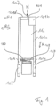
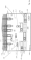
- FIG. 1 A straddle carrier, designated 101, is shown in a front view.
- the portal lift truck 101 essentially comprises a downwardly open U-shaped portal frame 101a, a load-carrying device in the form of a so-called spreader 102 and two travel carriers 103.
- the portal frame 101a with the travel carrier 103 encloses one on three sides and is therefore open to the front, back and bottom Space 112, which can at least partially accommodate a container 106 or two containers 105 and 106 one behind the other, viewed in a forward travel direction F1 of the straddle lift truck 101.
- the spreader 102 can be moved vertically in a lifting/lowering direction H along vertical portal supports 101c of the portal frame 101a.
- the two horizontal carriage beams 103 adjoin the lower end of the portal supports 101c.
- the spreader 102 includes a side displacement unit 110.
- an orientation of the straddle lift truck 101 - preferably based on its forward direction of travel F1 in the sense of a target direction of travel and accordingly based on fixed coordinates of a coordinate system of a work area - for example in a container stacking warehouse or in a sea-facing area of a container terminal and thus between
- the antennas 107a and 107b belong to a radio location system 107.
- the antennas 107a and 107b are preferably arranged in the area of a center M of the top of the straddle lift truck.
- the at least two antennas 107a and 107b can of course also be arranged in another predefined and known position, for example on the right or left on the top 101d, on the straddle lift truck 101, as long as they are spaced apart from one another with respect to a coordinate system of the radio location system 107 for position determination.
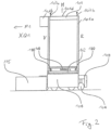
- the Figure 2 shows a side view of the portal lift truck 101 Figure 1 , which, in addition to the side displacement unit 110, has a longitudinal displacement unit 109 for the spreader 102, which serves to align the container 106 in its longitudinal direction relative to the spreader 102.
- the carriages 103 on which travel drives 104 with rubber-tired wheels are arranged, are located at the lower ends of the portal frame 101a and move to the left and right of the containers 105, 106 that are parked and to be parked.
- a driver's cab 101b is arranged, from which a driver looks in the direction of the forward travel direction F1 and operates the straddle lift truck 101.
- the two antennas 107a and 107b are arranged at the front and rear near the front V and near the rear R.
- An arrangement of a first antenna 107a to a second antenna 107b on the straddle lift truck 101 with a maximum distance from one another is advantageous;
- the two antennas 107a and 107b can also be arranged at a shorter distance.
- the Figure 3 shows a top view of the gantry lift truck 101 within a schematically shown radio location system 107 with active location marks 107c. It can be seen that the portal lift truck 101 with the portal frame 101a can drive over a container 106, which is arranged below the spreader 102 after driving over it.
- the spreader 102 is H-shaped and can hold and lift the container 106 at its four corner points using twist locks (not shown).
- a central horizontal longitudinal axis of the spreader 102 is also aligned in the direction of the forward travel direction F1, which means that the container 106 to be parked is arranged in a longitudinal orientation below and towards the portal frame 101a.
- the spreader 102 can be a so-called twin-lift spreader, which can be extended along its horizontal longitudinal axis and can accommodate two containers placed one behind the other.
- the antennas 107a and 107b can alternatively be arranged at the outer front and rear edges of the spreader 102.
- Radio location system 107 with the active location marks 107c and at least two antennas 107a, 107b per straddle lift truck 101 is provided.
- This local radio location system 107 includes several location marks 107c, which are distributed on the working area of the straddle lift truck 101, for example in a container terminal, and are therefore arranged terrestrially.
- the structure of the radiolocation system 107 corresponds to the radiolocation system described as prior art in the introduction to the description. With regard to the exemplary embodiment and the invention, reference is made to the content thereof.
- the orientation of the straddle lift truck 101 is also determined, since the position data is evaluated via the first antenna 107a and the second antenna 107b.
- the antennas 107a and 107b each separately receive position data 108 from the location marks 107c, which are then received and processed by a common receiver 107d.
- one receiver 107d can also be used for the antenna 107a and one receiver 107d for the antenna 107b.
- the processed position data is forwarded by the receiver 107d to a navigation computer 108, which then uses this to determine driving instructions for the straddle lift truck 101, for example for automatic control of the straddle lift truck in the sense of a driverless process and steering.
- the positions of the two antennas 107a, 107b on the gantry forklift 101 are stored in the navigation computer 108 in order to be able to determine the current orientation of the gantry forklift 101 from this.
- the positions of the two antennas 107a, 107b can be stored with reference to the center M of the straddle lift truck 101.
- the navigation computer 108 calculates from the current positions of the two antennas 107a, 107b, which, for example, each include an x and a y coordinate in a coordinate system of the working area of the gantry forklift 101, a type of reference position of the gantry forklift 101, for example based on its center M and a Alignment of the portal lift truck 101 or its longitudinal axis in the sense of a forward direction of travel F1 within the coordinate system of the work site.
- This orientation of the gantry lift truck 101 corresponds to an orientation angle.
- the invention is described below using the Figures 1 , 2 and 3 explained.
- the straddle lift truck 101 is driven by the driver over a container 106 to be picked up.
- the container 106 is picked up with the spreader 102 and raised.
- the driver then moves the straddle lift truck 101 to a desired position, typically at a container transfer point behind an already parked container 105 or to any other location within a container terminal, and lowers the spreader 102 to park the container 106 again.
- the portal lift truck 101 is steered manually by the driver to the desired position, for example.
- the driver can be supported with driving instructions via the radio positioning system 107, which provides position data, orientation data, destination information and direction information via a display.
- the driving instructions of the radio location system 107 can also be used for automatic steering of the gantry forklift 101 when driving over containers 105, 106 or also for automatically guided and therefore driverless gantry forklifts 101. This is achieved by the spaced arrangement of the antennas 107a and 107b, as well as the determination of position data 111 at two points, a high level of position determination accuracy is achieved, which enables precise control of the automatically guided gantry forklift truck 101.
- the position data 111 of the gantry forklift is compared with route information stored in the navigation computer 108 and a correction can be made if there is a deviation from the specified route. This can be done either with manual or preferably with automatic control.
- the desired position for the container 106 to be placed can be adjusted laterally in the transverse direction Q1 and in the direction of rotation D by a vertical direction in accordance with calculated control values Axis can be aligned in position by the side displacement unit 110 and thus corrected.
- a desired distance a between the parked container 105 and the container 106 to be parked can be set by the travel drive 104 or the longitudinal displacement unit 109 before the container 106 is parked.
- the straddle lift truck 101 can also be operated in a so-called twin-lift operation.
- the spreader 102 is a so-called twin-lift spreader. This means that the spreader 102 can accommodate two containers arranged one behind the other. For this purpose, the spreader 102 can be extended along its horizontal longitudinal axis.
- containers are understood to mean ISO containers.
- ISO containers weigh up to around 38 t and are generally understood to be standardized large containers with standardized pick-up points or corners for load-carrying devices.
- ISO containers are typically 20, 40, or 45 feet long.
- ISO containers with a length of 53 feet are already available.
- refrigerated containers so-called reefers, and a variety of other container types are also known.
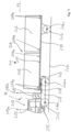
- the Figure 4 shows a schematic side view of an automatically guided transport vehicle 201 for containers 202.
- the transport vehicle 201 is designed, for example, as a tractor-trailer and accordingly includes a tractor 203, also known as a terminal truck, and a trailer 204 coupled to it in the form of a semi-trailer.
- a tractor 203 also known as a terminal truck
- a trailer 204 coupled to it in the form of a semi-trailer.
- semi-trailers have a total train weight of up to 200 t.
- the tractor 203 taken on its own and without the trailer 204 also represents a transport vehicle 201.
- the transport vehicle 201 can be moved freely on a floor area 206 via wheels 205 and is therefore floor-bound, but not rail-bound. Accordingly, the transport vehicle 201 must be distinguished from rail vehicles.
- the wheels 205 are each provided with tires, which are preferably rubber tires filled with air in the sense of tires.
- the transport vehicle 201 includes a travel drive with at least one motor designed as an electric motor and a transmission in order to drive the wheels 205.
- the engine and transmission are not shown for better clarity. In principle, an internal combustion engine is also conceivable instead of an electric motor.
- the wheels 205 are arranged in the usual manner on two axles 206a, 206b in the area of the tractor 203.
- Wheels 205 are arranged on at least one further third axle 206c of the trailer 204 designed as a semi-trailer. In principle, it is also possible to provide other numbers of axles and axle arrangements with a corresponding number of wheels 205 if this is technically necessary.
- the transport vehicle 201 or its tractor 203 comprises a chassis 207 on which the wheels 205 are mounted via the front first axle 206a and the rear second axle 206b.
- a fifth wheel plate 208 is arranged in the rear area of the chassis 207, which is part of a fifth wheel coupling.
- the fifth wheel plate 208 can be designed to be raised and lowered via a hydraulic drive, so that the tractor 203 can actively and independently connect or disconnect the trailer 204.
- the hydraulic lift of the fifth wheel plate 208 makes it possible to lift fifth wheel loads of up to 45 t.
- a different type of coupling and uncoupling of the trailer 204 without a hydraulic lifting option is also conceivable, for example using a manually operated coupling mechanism.
- the fifth wheel plate 208 can also be designed like a joint in such a way that no regular separation of the tractor 203 and trailer 204 is provided and thus permanently connects the tractor 203 and trailer 204 into a fixed unit in the form of a tractor-trailer.
- the chassis 207 carries a battery 209, which feeds the electric motor(s) of the travel drive of the transport vehicle 201 and is moved along with it.
- the battery 209 is preferably designed as a rechargeable lithium-ion battery or as a lead battery and is arranged above the chassis 207 or below it, for example between the two axles 206a, 206b, in order to enable easy replacement with a charged battery 209.
- an additional battery 209 can also be arranged on the trailer 204 to power the traction drive and can be electrically connected to the traction drive for this purpose.
- the trailer 204 designed as a semi-trailer does not have a front axle arranged at the end facing the tractor 203, but only one or more rear axles 206c, which are mounted under a frame 210 of the trailer 204 at the end facing away from the tractor 203.
- a kind of front axle of the trailer 204 is formed by the rear axle 206b of the tractor 203.
- the trailer 204 also has supports, not shown, which are arranged at its front end facing the tractor 203.
- the pillars are intended for parking the trailer 204 after uncoupling and, depending on the design of the fifth wheel plate 208, for attaching and detaching a trailer 204 designed as a semi-trailer from the tractor 203.
- the trailer 204 does not have its own drive.
- the transport vehicle 201 or its trailer 204 has a substantially flat loading area 211 for containers 202 on its frame 210.
- FIG. 5 As seen in the direction of travel F2 of the transport vehicle 201, two containers 202 designed as ISO containers with a length of approximately 20 feet are parked one behind the other.
- ISO containers in the sense defined above have standardized corner fittings.
- the corner fittings can, for example, be gripped by the load-carrying device of a crane designed as a so-called spreader frame in order to lift the ISO container from the loading area 211 or place it on it.
- the loading area 211 is delimited on its sides by several guide elements 211a.
- the guide elements 211a have guide surfaces with an oblique course.
- the guide surfaces extend from the loading surface 211 upwards and outwards and towards the loading surface 211 downwards and inwards.
- the guide elements 211a are preferably arranged in pairs on opposite sides, in particular long sides and/or narrow sides, of the loading surface 211.
- the guide surfaces of a pair of guide elements 211a form a kind of funnel, the oblique course of which tapers towards the loading surface 211 in order to realize the guiding and aligning function. Accordingly, the guide surfaces of a pair of guide members 211a expand upwardly away from the loading surface 211.
- the transport vehicle 201 is automatically guided in the sense defined above and has an in Figure 5 vehicle control 212 shown schematically.
- vehicle control 212 By means of the vehicle control 212, the driving maneuvers of the transport vehicle 201 can be controlled automatically, for example by carrying out planned transport orders via a control system and predetermined travel routes in this regard be implemented in control technology into appropriate driving maneuvers. In this context, steering operations and speeds as well as accelerations of the transport vehicle 201 are automatically controlled using the vehicle control 212.
- the transport vehicle 201 can optionally be guided or controlled manually by a driver in the sense defined above, so that a change between manual and automatic guidance of the transport vehicle 201 is also conceivable.
- a driver's cab 213 with corresponding control means for manual intervention in the vehicle control 212 is arranged in the front area of the tractor 203.
- the driver's cab 213 can be as in Figure 4 shown remain driverless or can be omitted.
- an orientation of the transport vehicle 201 - preferably based on its direction of travel F2 in the sense of a target direction of travel and accordingly based on fixed coordinates of a coordinate system of a work area 222 - for example in a container stacking warehouse or in a water-side area of a container based on the container stacking warehouse
- there are at least two antennas 215a and 215b on the top of the transport vehicle 201 which are one behind the other and spaced apart from one another when viewed in the longitudinal direction of the transport vehicle 201.
- the antennas 215a and 215b belong to a radio location system 214.
- the antennas 215a and 215b are preferably arranged centrally on the top of the tractor 203.
- the at least two antennas 215a and 215b can of course also be arranged in another predefined and known position, for example on the right or left of the chassis 207 on the tractor 203, as long as they are spaced apart from one another with respect to a coordinate system of the radio location system 214 for position determination.
- An arrangement of a first antenna 215a to a second antenna 215b on the tractor 203 with a maximum distance from one another is advantageous; However, the two antennas 215a and 215b can also be arranged at a shorter distance.
- the rear antenna 215b is arranged above the fifth wheel plate 208 so that it does not affect the range of motion of the trailer 204 even at the maximum articulation angle between the tractor 203 and the trailer 204.
- the driver's cab 213 is arranged between the two antennas 215a, 215b.
- FIG 5 is a schematic top view of a terminal 223 designed, for example, as a port terminal for handling containers 202 using the transport vehicles 201 described above Figure 4 shown.
- Several ships 224 can dock at a quay 216 in a port to deliver or pick up containers 202.
- 216 handling equipment in the form of container bridges 217 is provided on the quay, which are also referred to as ship-to-shore cranes (STS crane for short) and whose booms extend over the ships 224 on the one hand and on the other extend over quay 216.
- STS crane ship-to-shore cranes
- the ships 224 can also be loaded or unloaded using so-called harbor cranes or mobile harbor cranes, the boom of which is pivoted about a vertical axis over the corresponding ship 224. This is particularly true when it comes to smaller terminals 223 or work areas 222.
- the terminal 223 is separated from its external environment by a boundary 223a designed as a fence or wall and can only be reached via passing areas 223b by external transport vehicles 225 traveling in public transport, for example conventional trucks, in order to pick up or deliver containers 202.
- external transport vehicles 225 traveling in public transport, for example conventional trucks, in order to pick up or deliver containers 202.
- a security gate for logging in and out, including identification of the external vehicles entering and leaving and their drivers, can also be provided there.
- the terminal 223 includes within the boundary 223a a container stacking warehouse 218, in which containers 202 can be stacked for short-term interim storage in at least one storage area 218a, also referred to as a stack. This may be the case after the containers 202 have been unloaded from the ships 224 and before they are loaded onto a road or rail vehicle for further transport outside the terminal 223 or after they have been delivered therefrom and before they are loaded onto the ships 224.
- the internal transport vehicles 201 which are not designed and approved for public transport, move over the corridor area 206 surrounding the quay 216 of the port in order to transport the containers 202, which are designed, for example, as ISO containers the container bridges 217 and the container stacking cranes 219 designed as gantry cranes of the container stacking warehouse 218 of the terminal 223.
- the container stack storage 218 in such a terminal 223 comprises a plurality of storage areas 218a, each of which is arranged in rows or in a grid-like manner next to one another and spaced apart from one another.
- each storage area 218a several rows of containers 202 can be placed with their long sides next to each other and several containers 202 per row can be placed one above the other.
- at least one corresponding gantry crane is provided for each storage area 218a of the container stacking warehouse 218 in order to transport containers 202 for storage or retrieval in the To take over the container stacking warehouse 218 from the transport vehicles 201 or to hand it over to them.
- the gantry cranes representing handling equipment span the corresponding storage area 218a and the containers 202 stacked therein with their crane girders supported by gantry supports.
- the container stacking cranes 219 can move over the storage area 218a in its longitudinal direction.
- the transport vehicles 201 move in a work area 222 within the boundary 223a of the terminal 223.
- transport vehicle 201 which is an internal and preferably automatically guided vehicle in the sense of the above definition
- at least one manually guided external transport vehicle 225 which
- transport vehicles 201 in the manual version of the in Figure 4 The transport vehicle 201 described with a driver's cab 205 can operate in the work area 222 in addition to or as an alternative to the automatically guided variant.
- the containers 202 are transported between the container stacking warehouse 218 or its handling equipment and the handling equipment arranged on the quay 216 in the form of the container bridges 217 or harbor cranes or mobile harbor cranes in which the containers 202 can be transshipped between the transport vehicles 201 and the ships 224 and accordingly the transport vehicles 201 can be loaded and unloaded on the quay 216.
- the external transport vehicles 225 containers 202 can be picked up from the container stacking warehouse 218 or its handling device for further transport in public transport or can be delivered for interim storage in the container stacking warehouse 218 after transport in public transport. These transports take place in what is known as horizontal transport.
- the gantry cranes assigned to the storage areas 218a as handling equipment are in Figure 5 designed as so-called rubber-tired stacking cranes (Rubber-Tyred Gantry Crane - RTG for short) or rail-mounted stacking cranes (Rail-Mounted Gantry Crane - RMG for short), which are either manually guided or controlled by an operator traveling in a crane cabin or (partially ) can be managed or controlled automatically. Accordingly, this will be in Figure 5 Terminal 223 shown schematically is also referred to as an RMG or RTG terminal.
- straight-line and grid-shaped single or multi-lane lanes L, Q2 are provided, in which the internal transport vehicles 201 and those entering and exiting the terminal 223 via the passing area 223b external transport vehicles 225 can move.
- the loading and unloading of the transport vehicles 201, 225 by the container stacking cranes 219 takes place in the longitudinal aisles L of the storage areas 218a leading along the long sides.
- lanes serving as transfer lanes or transfer areas are provided for the transport vehicles 201, 225, which are also spanned by the respective container stacking cranes 219.
- each storage area 218a can have at least one container stacking crane 219 be assigned.
- the area of the quay 216 with the handling equipment there can be reserved for the internal transport vehicles 201, which is why appropriate barriers or passing areas with security gates can be provided within the terminal 223. This is indicated by the dashed line in Figure 5 indicated.
- FIG 5a an alternative terminal 223 is shown, which is designed as a so-called ASC terminal.
- the container stacking cranes 219 of the container stacking warehouse 218 are designed here as gantry cranes in the form of so-called automated and rail-bound stacking cranes, which are also referred to as Automated Stacking Crane - ASC for short.
- Automated Stacking Crane - ASC Automated Stacking Crane - ASC for short.
- this type of terminal only narrow alleys are provided between the storage areas 218a as travel routes for the ASCs.
- the routes for include rails 226 on which the respective ASC moves and between whose pairs a storage area 218a is arranged. These lanes are not intended for transport vehicles 201 and 225 to pass through and are generally too narrow for this.
- the storage areas 218a do not extend along and in particular parallel, but usually transversely and in particular perpendicular to the quay 216.
- the container stacking cranes 219 also move accordingly transversely to the quay 216.
- the container -Stack storage 218 of the ASC terminal does not have any transfer tracks or transfer areas arranged on the long sides of the storage areas 218a. Instead, head-side transfer areas are provided at the longitudinal ends of the respective storage area 218a pointing in the longitudinal direction.
- the work area 222 in such an ASC terminal includes a water-side or quay-side transshipment area with respect to the container stacking warehouse 218, which is separated from the land-side traffic of external transport vehicles 225 in the land-side transshipment area 222a by the above-described design of the ASC terminal during regular operation of the terminal 223 .
- vehicles can move between the waterside transshipment area and the landside transshipment area 222a, for which lanes with sufficient width can then be used.
- the transport vehicles 225 use a passing area 223b in the above to enter or exit the transshipment area 222a senses.
- the Figure 6 shows a top view of a transport vehicle 201 within a schematically shown radio location system 214 with active location marks 215c.
- the radio positioning system 214 is in the terminal 223 Figure 5 respectively Figure 5a and in particular its respective work area 222 set up.
- the radio location system 214 is included the active location marks 215c and at least two antennas 215a, 215b per transport vehicle 201.
- This local radio positioning system 214 includes several location marks 215c, which are distributed in the working area 222 of the transport vehicle 201 in the terminal 223 and are therefore arranged terrestrially.
- the structure of the radiolocation system 214 corresponds to the radiolocation system described as prior art in the introduction to the description. With regard to the exemplary embodiment and the invention, reference is made to the content thereof.
- the orientation of the tractor 203 is also determined, since the position data is evaluated via the first antenna 215a and the second antenna 215b.
- the antennas 215a and 215b each separately receive position data 220 from the location marks 215c, which are then received and processed by a common receiver 215d.
- a common receiver 215d can also be used for the antenna 215a and one receiver 215d for the antenna 215b.
- the processed position data is forwarded by the receiver 215d to a navigation computer 221, which then uses this to determine driving instructions for the transport vehicle 201, for example for automatic control of the transport vehicle 201 in the sense of a driverless process and steering.
- the positions of the two antennas 215a, 215b on the transport vehicle 201 or the tractor 203 are stored in the navigation computer 221 in order to be able to determine the current orientation of the transport vehicle 201 from this.
- the navigation computer 221 also evaluates this data supplied by a sensor system for determining the bend angle.
- the positions of the two antennas 215a, 215b can be stored with reference to the center M of the tractor 203.
- the navigation computer 221 calculates from the current positions of the two antennas 215a, 215b, which, for example, each include an x and a y coordinate in a coordinate system of the working area 222 of the transport vehicle 201, a type of reference position of the tractor 203 or its center M and an orientation the tractor 203 or its longitudinal axis in the sense of a forward direction of travel F2 within the coordinate system of the working area 222.
- This orientation of the tractor 203 corresponds to an orientation angle.
- the transport vehicle 201 is driven by the driver to pick up or deliver a container 202, for example to a container bridge 217 or a container stacking crane 219. After handing over a container 202, the driver moves the transport vehicle 201 to a desired position within a work area 222.
- the transport vehicle 201 is steered manually, for example, to the desired position by the driver.
- the driver can be supported with driving instructions via the radio positioning system 214, which provides him with position data, orientation data, destination information and direction information via a display.
- the driving instructions of the radio location system 214 can also be used for automatic steering of the transport vehicle 201, for example when approaching container bridges 217 or container stacking cranes 219, or also with automatically guided and therefore driverless transport vehicles 201. This is done by the spaced arrangement of the antennas 215a and 215b, as well as the determination of position data 220 at two points, achieves a high level of position determination accuracy, which enables precise control of the automatically guided transport vehicle 201.
- the position data 220 of the transport vehicle 201 are compared with route information stored in the navigation computer 221 and a correction can be made if there is a deviation from the predetermined route. This can either with manual or preferably with automatic control.
Landscapes
- Engineering & Computer Science (AREA)
- Automation & Control Theory (AREA)
- Mechanical Engineering (AREA)
- Physics & Mathematics (AREA)
- General Physics & Mathematics (AREA)
- Radar, Positioning & Navigation (AREA)
- Remote Sensing (AREA)
- Aviation & Aerospace Engineering (AREA)
- Traffic Control Systems (AREA)
- Control Of Position, Course, Altitude, Or Attitude Of Moving Bodies (AREA)
- Warehouses Or Storage Devices (AREA)
Description
Die Erfindung betrifft ein System zur Funkortung eines Transportfahrzeugs für Container gemäß dem Oberbegriff von Anspruch 1.The invention relates to a system for radiolocation of a transport vehicle for containers according to the preamble of
Transportfahrzeuge im Sinne der vorliegenden Erfindung können Portalhubstapler oder als Schwerlastfahrzeuge ausgebildete Flurförderfahrzeuge sein, die für die Handhabung und/oder den Transport von Containern, insbesondere als rein innerbetriebliche beziehungsweise interne Fahrzeuge in Containerterminals zum Umschlag von Containern, ausgelegt sind. Die zu transportierenden beziehungsweise handzuhabenden Container können dementsprechend insbesondere im Fall von ISO-Containern im beladenen Zustand bis zu 40 t wiegen und normierte oder zumindest standardisierte Längen von zum Beispiel 10, 20, 40, 45, 53 oder 60 Fuß aufweisen. Die beiden letztgenannten Längen werden bisher als nicht ISO genormte Container ausschließlich in Nordamerika eingesetzt. In diesem Zusammenhang werden unter ISO-Containern genormte Großraum- beziehungsweise Seefrachtcontainer verstanden, die im internationalen Warenverkehr zum Einsatz kommen. In diesem Zusammenhang können Container auch andere normierte oder zumindest standardisierte Ladungsträger wie beispielsweise Wechselaufbauten, insbesondere Wechselbehälter oder Wechselbrücken, sein.Transport vehicles in the sense of the present invention can be straddle lift trucks or industrial trucks designed as heavy-duty vehicles, which are designed for the handling and / or transport of containers, in particular as purely internal or internal vehicles in container terminals for the handling of containers. The containers to be transported or handled can accordingly weigh up to 40 t when loaded, particularly in the case of ISO containers, and have standardized or at least standardized lengths of, for example, 10, 20, 40, 45, 53 or 60 feet. The last two lengths mentioned have so far been used as non-ISO standardized containers exclusively in North America. In this context, ISO containers are standardized large-capacity or sea freight containers that are used in international goods transport. In this context, containers can also be other standardized or at least standardized load carriers such as swap bodies, in particular swap bodies or swap bodies.
Transportfahrzeuge in Form der genannten Schwerlastfahrzeuge werden auch als Terminal Truck oder Terminal Tractor bezeichnet, da sie zusammen mit einem oder mehreren Anhängern als eine Art Sattelzug eingesetzt werden. Die Ladefläche der Anhänger ist von Führungselementen begrenzt. Die zueinander beabstandeten Führungselemente werden auch als Einweiser bezeichnet und führen einen aufzunehmenden Container beziehungsweise dessen Eckbeschläge auf die Ladefläche. Hierfür erstrecken sich die Führungselemente mit ihren Führungsflächen schräg nach außen und oben von der Ladefläche weg. Derartige Transportfahrzeuge sind beispielsweise aus
Aus der Gebrauchsmusterschrift
Neben dieser automatischen Lenkung mittels Laserscanner, die eine Positionsbestimmung des Portalhubstapler relativ zu einem abgestellten Container im Zentimeterbereich bei geringem Aufwand ermöglicht, können die Portalhubstapler auch mit Navigationssystemen ausgerüstet sein, die von der Navigation von fahrerlosen Flurförderfahrzeugen allgemein bekannt sind. Hierbei handelt es sich um die folgenden Einzelsysteme oder Kombinationen hiervon: Satellitennavigation (differentielles GPS), Radarnavigation, Trägheitsnavigation (Gyroskope), Transpondernavigation (mit im Boden eingelassen Transpondern oder Magneten und Antennen am Fahrzeug) oder Leitdrahtnavigation.In addition to this automatic steering using a laser scanner, which enables the position of the straddle lift truck to be determined relative to a parked container in the centimeter range with little effort, the straddle lift truck can also be equipped with navigation systems, which are generally known from the navigation of driverless industrial trucks. These are the following individual systems or combinations thereof: satellite navigation (differential GPS), radar navigation, inertial navigation (gyroscopes), Transponder navigation (with transponders embedded in the ground or magnets and antennas on the vehicle) or guidewire navigation.
Ein System mit den Merkmalen des Oberbegriffs des Anspruchs 1 ist aus der
Aus der europäischen Patentschrift
Aus der
Die
Aus der
In der
Aus der
Die
Aus der
Der Erfindung liegt die Aufgabe zugrunde, ein verbessertes System zur Funkortung eines Transportfahrzeugs für Container innerhalb eines Arbeitsbereichs zu schaffen.The invention is based on the object of creating an improved system for radiolocation of a transport vehicle for containers within a work area.
Diese Aufgabe wird durch ein System mit den Merkmalen des Anspruches 1 gelöst. Vorteilhafte Ausgestaltungen der Erfindung sind in den abhängigen Ansprüchen 2 und 3 und der nachfolgenden Beschreibung angegeben.This task is solved by a system with the features of
Erfindungsgemäß wird ein verbessertes System zur Funkortung eines Transportfahrzeugs für Container innerhalb eines Arbeitsbereichs eines Containerterminals zum Umschlag von Containern, mit einem Funkortungssystem umfassend mehrere aktive terrestrisch angeordnete und Positionsdaten sendende Ortsmarken, die Positionsdaten empfangende Antennen, mindestens einem die empfangenen Positionsdaten verarbeitenden Empfänger und mit mindestens einem Transportfahrzeug für Container mit mindestens einer der Antennen mit Empfänger und einem die Positionsdaten in Fahranweisungen für das Transportfahrzeug umsetzenden Navigationsrechner, wobei das Transportfahrzeug ein Portalhubstapler für Container oder eine Zugmaschine für einen und/oder mit einem Anhänger mit einer von Führungselementen begrenzten Ladefläche für Container ist, dadurch geschaffen, dass an dem Transportfahrzeug mindestens zwei der Antennen angeordnet sind, welche die von den Ortsmarken gesendeten Positionsdaten jeweils getrennt voneinander empfangen, wobei die mindestens zwei Antennen voneinander beabstandet sind und der Navigationsrechner neben der Position des Transportfahrzeugs auch die Ausrichtung des Transportfahrzeugs aus den Positionsdaten der mindestens zwei Antennen ermittelt.According to the invention, an improved system for radiolocation of a transport vehicle for containers within a working area of a container terminal for handling containers, with a radiolocation system comprising a plurality of active terrestrially arranged placemarks that send position data, the antennas that receive position data, at least one receiver that processes the received position data and with at least one Transport vehicle for containers with at least one of the antennas with a receiver and a navigation computer that converts the position data into driving instructions for the transport vehicle, the transport vehicle being a straddle lift truck for containers or a tractor for a and/or with a trailer with a loading area for containers delimited by guide elements, created in that at least two of the antennas are arranged on the transport vehicle, which each receive the position data sent by the location marks separately from one another, the at least two antennas being spaced apart from one another and the navigation computer next to the position of the Transport vehicle also determines the orientation of the transport vehicle from the position data of the at least two antennas.
Nach einer ersten Variante der Erfindung ist hierbei vorgesehen, dass das Transportfahrzeug ein Portalhubstapler für Container ist. Dabei ist dann vorgesehen, dass an dem Portalhubstapler die mindestens zwei Antennen angeordnet sind, die mindestens zwei Antennen voneinander beabstandet sind und der Navigationsrechner neben der Position des Portalhubstaplers auch die Ausrichtung des Portalhubstaplers bezogen auf dessen Vorwärtsfahrtrichtung, insbesondere innerhalb des Arbeitsbereichs bezogen auf ein Koordinatensystem des Arbeitsbereichs, aus den Positionsdaten der mindestens zwei Antennen ermittelt. Durch die Verwendung von zwei Antennen kann vorteilhafter Weise auch die Ausrichtung des Portalhubstaplers bestimmt werden, wodurch insbesondere in Bezug auf die Handhabung von Containern eine Ausrichtung des Portalhubstaplers zu den Containern oder eine gezieltes Abstellen der Container erleichtert wird. Fahrer eines Portalhubstaplers können beim Lenken unterstützt werden oder der Portalhubstapler kann insgesamt automatisch geführt werden. Hiermit geht dann eine optimale Platzausnutzung von genau abgestellten Containern in einem Containerlager einher. Ein weiterer Vorteil der Verwendung von zwei Antennen ist auch darin zu sehen, dass Funkortungssysteme grundsätzlich Ungenauigkeiten wie Mehrwegausbreitung und Mehrdeutigkeit von Positionslösungen unterliegen. Durch die Kombination von zwei Antennen und somit von zwei Messsystemen in festem Abstand zueinander und der zugehörigen Positionsdaten kann die Genauigkeit als auch die Zeit für die Bestimmung einer genauen Positionslösung wesentlich verbessert werden.According to a first variant of the invention, it is provided that the transport vehicle is a straddle lift truck for containers. It is then provided that the at least two antennas are arranged on the gantry forklift, the at least two antennas are spaced apart from one another and the navigation computer, in addition to the position of the gantry forklift, also determines the orientation of the gantry forklift in relation to its forward direction of travel, in particular within the working area in relation to a coordinate system of the Working area, determined from the position data of at least two antennas. By using two antennas, the orientation of the straddle forklift can also be advantageously determined, which makes it easier to align the straddle forklift with the containers or to place the containers in a targeted manner, particularly with regard to the handling of containers. Drivers of a straddle lift truck can be assisted in steering or the straddle lift truck can be guided automatically as a whole. This is accompanied by optimal use of space for precisely placed containers in a container warehouse. Another advantage of using two antennas is that radio positioning systems are fundamentally subject to inaccuracies such as multipath propagation and ambiguity of position solutions. By combining two antennas and thus two measuring systems at a fixed distance from one another and the associated position data, the accuracy and the time for determining an exact position solution can be significantly improved.
Im Sinne der Erfindung gemäß der ersten Variante ist das Umsetzen der Positionsdaten in Fahranweisungen für den Portalhubstapler durch den Navigationsrechner so zu verstehen, dass je nach Betrieb des Portalhubstaplers manuell, halbautomatisch oder automatisch die Fahranweisungen in geeigneter Weise zur Verfügung gestellt werden, d. h. beispielsweise dem Fahrer als Anzeige oder einer automatischen Fahrzeugsteuerung als Sollwerte. Die Kombination von zwei Antennen und zwei Messsystemen ist daher besonders vorteilhaft für die automatische Fahrzeugsteuerung, da diese sehr präzise Positions- und auch Orientierungsdaten erfordert. Auch ist eine hohe Genauigkeit der Bestimmung der Positionsdaten erforderlich für die automatische Navigation des Portalhubstaplers auf einer vorgegebenen Route innerhalb des Arbeitsbereichs. Um Kollisionen innerhalb des Arbeitsbereichs zu vermeiden, ist daher eine Bestimmung der genauen Position des Portalhubstaplers in einer möglichst geringen Zeit erforderlich.In the sense of the invention according to the first variant, the conversion of the position data into driving instructions for the gantry forklift by the navigation computer is to be understood as meaning that, depending on the operation of the gantry forklift, the driving instructions are provided in a suitable manner manually, semi-automatically or automatically, that is, for example to the driver as a display or an automatic vehicle control as setpoints. The combination of two antennas and two measuring systems is therefore particularly advantageous for automatic vehicle control, as this requires very precise position and orientation data. A high degree of accuracy in determining the position data is also required for the automatic navigation of the straddle lift truck a predetermined route within the work area. In order to avoid collisions within the work area, it is therefore necessary to determine the exact position of the straddle lift truck in as short a time as possible.
Nach einer zweiten Variante der Erfindung ist vorgesehen, dass das Transportfahrzeug eine Zugmaschine für einen Anhänger mit einer Ladefläche für Container ist. Dabei ist dann vorgesehen, dass an der Zugmaschine die mindestens zwei Antennen angeordnet sind, die mindestens zwei Antennen voneinander beabstandet sind und der Navigationsrechner neben der Position der Zugmaschine auch die Ausrichtung der Zugmaschine bezogen auf ein Koordinatensystem des Arbeitsbereichs aus den Positionsdaten der mindestens zwei Antennen ermittelt. Die Ausrichtung bezieht sich somit auch auf eine Fahrtrichtung im Sinne einer Soll-Fahrtrichtung der Zugmaschine. Durch die Verwendung von zwei Antennen kann vorteilhafter Weise auch die Ausrichtung des Transportfahrzeugs bestimmt werden, wenn das Transportfahrzeug auch einen an die Zugmaschine gekoppelten Anhänger umfasst. Dadurch ist insbesondere in Bezug auf die Handhabung von Containern eine Ausrichtung des Transportfahrzeugs zu den Umschlaggeräten für ein gezieltes Abstellen oder Aufnehmen der Container auf oder von dem Anhänger des Transportfahrzeugs erleichtert. In diesem Zusammenhang kann der Navigationsrechner den von einer Sensorik ermittelten Knickwinkel zwischen der Längsachse der Zugmaschine und der Längsachse des Anhängers verwenden, um auch die Position und Ausrichtung des Anhängers zu bestimmen. Fahrer eines Transportfahrzeugs können beim Lenken unterstützt werden oder das Transportfahrzeug kann insgesamt automatisch geführt werden. Hiermit geht dann eine optimale Platzausnutzung von Fahrspuren in dem Arbeitsbereich und Vermeidung von Kollisionen mit anderen Objekten, beispielsweise anderen Transportfahrzeugen, einher. Ein weiterer Vorteil der Verwendung von zwei Antennen ist auch darin zu sehen, dass Funkortungssysteme grundsätzlich Ungenauigkeiten wie Mehrwegausbreitung und Mehrdeutigkeit von Positionslösungen unterliegen. Durch die Kombination von zwei Antennen und somit von zwei Messsystemen in festem Abstand zueinander und der zugehörigen Positionsdaten kann die Genauigkeit als auch die Zeit für die Bestimmung einer genauen Positionslösung wesentlich verbessert werden.According to a second variant of the invention it is provided that the transport vehicle is a tractor for a trailer with a loading area for containers. It is then provided that the at least two antennas are arranged on the tractor, the at least two antennas are spaced apart from one another and the navigation computer, in addition to the position of the tractor, also determines the orientation of the tractor in relation to a coordinate system of the work area from the position data of the at least two antennas . The alignment therefore also refers to a direction of travel in the sense of a target direction of travel of the tractor. By using two antennas, the orientation of the transport vehicle can also advantageously be determined if the transport vehicle also includes a trailer coupled to the tractor. This makes it easier, particularly with regard to the handling of containers, to align the transport vehicle with the handling equipment for targeted parking or picking up of the containers on or from the trailer of the transport vehicle. In this context, the navigation computer can use the articulation angle determined by a sensor between the longitudinal axis of the tractor and the longitudinal axis of the trailer to also determine the position and orientation of the trailer. Drivers of a transport vehicle can be assisted in steering or the transport vehicle can be guided automatically as a whole. This is accompanied by optimal use of space in lanes in the work area and avoidance of collisions with other objects, such as other transport vehicles. Another advantage of using two antennas is that radio positioning systems are fundamentally subject to inaccuracies such as multipath propagation and ambiguity of position solutions. By combining two antennas and thus two measuring systems at a fixed distance from one another and the associated position data, the accuracy and the time for determining an exact position solution can be significantly improved.
Im Sinne der Erfindung gemäß der zweiten Variante ist das Umsetzen der Positionsdaten in Fahranweisungen für das Transportfahrzeug durch den Navigationsrechner so zu verstehen, dass je nach Betrieb des Transportfahrzeugs manuell, halbautomatisch oder automatisch die Fahranweisungen in geeigneter Weise zur Verfügung gestellt werden, d. h. beispielsweise dem Fahrer als Anzeige oder einer automatischen Fahrzeugsteuerung als Sollwerte. Die Kombination von zwei Antennen und zwei Messsystemen ist daher besonders vorteilhaft für die automatische Fahrzeugsteuerung, da diese sehr präzise Positions- und auch Orientierungsdaten im Sinne der Ausrichtung erfordert. Auch ist eine hohe Genauigkeit der Bestimmung der Positionsdaten erforderlich für die automatische Navigation des Transportfahrzeugs auf einer vorgegebenen Route innerhalb des Arbeitsbereichs. Um Kollisionen innerhalb des Arbeitsbereichs zu vermeiden, ist daher eine Bestimmung der genauen Position des Transportfahrzeugs in einer möglichst geringen Zeit erforderlich.In the sense of the invention according to the second variant, the implementation is Position data in driving instructions for the transport vehicle by the navigation computer is to be understood in such a way that, depending on the operation of the transport vehicle, the driving instructions are made available in a suitable manner manually, semi-automatically or automatically, that is, for example, to the driver as a display or to an automatic vehicle control as setpoints. The combination of two antennas and two measuring systems is therefore particularly advantageous for automatic vehicle control, as this requires very precise position and orientation data in terms of alignment. A high degree of accuracy in determining the position data is also required for the automatic navigation of the transport vehicle on a predetermined route within the work area. In order to avoid collisions within the work area, it is therefore necessary to determine the exact position of the transport vehicle in the shortest possible time.
In vorteilhafter Weise ist vorgesehen, dass die Ortsmarken Positionssignale als vorbestimmte Sequenzen mit einem Zeitmultiplexverfahren aussenden.Advantageously, it is provided that the location marks send out position signals as predetermined sequences using a time division multiplex method.
Besonders vorteilhaft ist vorgesehen, dass die Antenne als TDMA adaptive Richtantenne ausgebildet ist. Hierdurch wird eine Ungenauigkeit durch Mehrwegausbreitung von Funksignalen vermindert.It is particularly advantageous for the antenna to be designed as a TDMA adaptive directional antenna. This reduces inaccuracy caused by multipath propagation of radio signals.
Nachfolgend wird die Erfindung an Hand eines in einer Zeichnung dargestellten Ausführungsbeispiels zur ersten Variante und an Hand eines in einer Zeichnung dargestellten Ausführungsbeispiels zur zweiten Variante näher erläutert. Es zeigen:
-
Figur 1 -
Figur 2Figur 1 , -
Figur 3 eine Draufsicht auf denPortalhubstapler aus Figur 1 innerhalb eines Funkortungssystems mit aktiven Ortsmarken, -
Figur 4 eine Seitenansicht eines Transportfahrzeugs in Form einer Zugmaschine, -
Figur 5 eine schematische Ansicht eines Terminals zum Umschlag von Containern unter Einsatz der Transportfahrzeuge gemäßFigur 4 , -
Figur 5a eine schematische Ansicht eines alternativen Terminals zum Umschlag von Containern unter Einsatz der Transportfahrzeuge gemäßFigur 4 und -
Figur 6 eine Draufsicht auf das Transportfahrzeug ausFigur 4 innerhalb eines schematisch dargestellten Funkortungssystems mit aktiven Ortsmarken.
-
Figure 1 a front view of a straddle lift truck, -
Figure 2 a side view of the straddle lift truckFigure 1 , -
Figure 3 a top view of the straddle lift truckFigure 1 within a radio positioning system with active placemarks, -
Figure 4 a side view of a transport vehicle in the form of a tractor, -
Figure 5 a schematic view of a terminal for handling containers using the transport vehiclesFigure 4 , -
Figure 5a a schematic view of an alternative terminal for handling containers using the transport vehicles according toFigure 4 and -
Figure 6 a top view of the transport vehicleFigure 4 within a schematically shown radio location system with active placemarks.
In
Um neben einer Position auch eine Ausrichtung des Portalhubstaplers 101 - vorzugsweise bezogen auf dessen Vorwärtsfahrtrichtung F1 im Sinne einer Soll-Fahrtrichtung und dementsprechend bezogen auf ortsfeste Koordinaten eines Koordinatensystems eines Arbeitsbereichs - beispielsweise in einem Containerstapellager oder in einem seeseitigen Bereich eines Container-Terminals und somit zwischen dem Containerstapellager und Schiffsentladekranen und dort dann auch unter anderen Portalhubstaplern bestimmen zu können, befinden sich auf einer Oberseite 101d des Portalrahmens 101a mindestens zwei Antennen 107a und 107b, die in Vorwärtsfahrtrichtung F1 des Portalhubstaplers 101 gesehen hintereinander und voneinander beabstandet sind. Die Antennen 107a und 107b gehören zu einem Funkortungssystem 107. Bevorzugt sind die Antennen 107a und 107b im Bereich einer Mitte M der Oberseite des Portalhubstaplers angeordnet. Die mindestens zwei Antennen 107a und 107b können selbstverständlich auch in einer anderen vordefinierten und bekannten Position, beispielsweise rechts oder links auf der Oberseite 101d, an dem Portalhubstapler 101 angeordnet sein, solange diese in Bezug auf ein Koordinatensystem des Funkortungssystems 107 zur Positionsbestimmung voneinander beabstandet sind.In order to, in addition to a position, also an orientation of the straddle lift truck 101 - preferably based on its forward direction of travel F1 in the sense of a target direction of travel and accordingly based on fixed coordinates of a coordinate system of a work area - for example in a container stacking warehouse or in a sea-facing area of a container terminal and thus between In order to be able to determine the container stacking warehouse and ship unloading cranes and there also among other gantry forklifts, there are at least two
Die
Die
Um einem Portalhubstapler 101 innerhalb eines Containerterminals Fahranweisungen zur Verfügung stellen zu können, die neben einer aktuellen absoluten Position auch die aktuelle Ausrichtung des Portalhubstaplers 101 beinhalten, ist das Funkortungssystem 107 mit den aktiven Ortsmarken 107c und mindestens zwei Antennen 107a, 107b je Portalhubstapler 101 vorgesehen. Dieses lokale Funkortungssystem 107 umfasst mehreren Ortsmarken 107c, welche auf dem Arbeitsgelände des Portalhubstaplers 101, beispielsweise in einem ContainerTerminal, verteilt und somit terrestrisch angeordnet sind. Das Funkortungssystem 107 stimmt vom Aufbau mit dem in der Beschreibungseinleitung als Stand der Technik beschriebenen Funkortungssystem überein. In Bezug auf das Ausführungsbeispiel und die Erfindung wird somit inhaltlich hierauf Bezug genommen. Mit Hilfe des Funkortungssystems 107 wird neben der absoluten Position auch die Ausrichtung des Portalhubstaplers 101 bestimmt, da die Positionsdaten über die erste Antenne 107a und die zweite Antenne 107b ausgewertet werden. Die Antennen 107a und 107b empfangen getrennt voneinander jeweils Positionsdaten 108 von den Ortsmarken 107c, die dann von einem gemeinsamen Empfänger 107d empfangen und verarbeitet werden. Selbstverständlich kann aber auch jeweils ein Empfänger 107d für die Antenne 107a und ein Empfänger 107d für die Antenne 107b verwendet werden. Die verarbeiteten Positionsdaten werden von dem Empfänger 107d an einen Navigationsrechner 108 weitergeleitet, der hieraus dann Fahranweisungen für den Portalhubstapler 101 bestimmt, beispielsweise zur automatischen Steuerung des Portalhubstaplers im Sinne eines fahrerlosen Verfahrens und Lenkens. Hierfür sind in dem Navigationsrechner 108 die Positionen der beiden Antennen 107a, 107b auf dem Portalhubstapler 101 hinterlegt, um hieraus die aktuelle Ausrichtung des Portalhubstaplers 101 bestimmen zu können. Die Positionen der beiden Antennen 107a, 107b kann mit Bezug zur Mitte M des Portalhubstaplers 101 hinterlegt sein. Der Navigationsrechner 108 berechnet aus den aktuellen Positionen der beiden Antennen 107a, 107b, welche beispielsweise jeweils eine x- und eine y-Koordinate in einem Koordinatensystem des Arbeitsgeländes des Portalhubstaplers 101 umfassen, eine Art Referenzposition des Portalhubstaplers 101 beispielweise bezogen auf dessen Mitte M und eine Ausrichtung des Portalhubstaplers 101 beziehungsweise dessen Längsachse im Sinne einer Vorwärtsfahrtrichtung F1 innerhalb des Koordinatensystems des Arbeitsgeländes. Diese Ausrichtung des Portalhubstaplers 101 entspricht einem Orientierungswinkel.In order to be able to provide a
Im Folgenden wird die Erfindung anhand der
Ebenfalls möglich ist eine Navigation des Portalhubstaplers 101 auf vorgegebenen Routen innerhalb des Arbeitsbereichs. Dabei werden die Positionsdaten 111 des Portalhubstaplers mit in dem Navigationsrechner 108 hinterlegten Streckeninformationen abgeglichen und bei Abweichung von der vorgegebenen Route kann eine Korrektur erfolgen. Dies kann entweder mit manueller aber bevorzugt mit automatischer Steuerung erfolgen.It is also possible to navigate the
Entsprechend von ermittelten Positionsdaten des Portalhubstaplers 101 und den vorbestimmten Positionsdaten des abzustellenden Containers 105, 106 kann je nach Genauigkeit der von dem Portalhubstapler 101 angefahrenen Position die gewünschte Position für den abzusetzenden Container 106 entsprechend berechneter Stellwerte seitlich in Querrichtung Q1 und in Drehrichtung D um eine vertikale Achse durch die Seitenverschubeinheit 110 in seiner Position ausgerichtet und somit korrigiert werden. Ein gewünschter Abstand a zwischen abgestelltem Container 105 und abzustellendem Container 106 kann vor dem Abstellen des Containers 106 durch den Fahrantrieb 104 oder die Längsverschubeinheit 109 eingestellt werden.According to the determined position data of the
Der Portalhubstapler 101 kann auch in einem sogenannten Twin-Lift-Betrieb betrieben werden. Hierbei ist der Spreader 102 ein sogenannter Twin-Lift-Spreader. Das bedeutet, dass der Spreader 102 zwei hintereinander angeordnete Container aufnehmen kann. Zu diesem Zweck ist der Spreader 102 entlang seiner horizontalen Längsachse ausfahrbar.The
In Verbindung mit der vorliegenden Erfindung werden unter Containern ISO-Container verstanden. ISO-Container wiegen bis zu etwa 38 t und werden allgemein als genormte Großbehälter mit genormten Aufnahmepunkten oder -ecken für Lastaufnahmemittel verstanden. ISO-Container sind üblicherweise 20, 40 oder 45 Fuß lang. Auch ISO-Container in einer Länge von 53 Fuß gibt es bereits. Im Bereich der ISO-Container sind neben den geschlossenen Containern auch Kühl-Containersogenannte Reefer - und eine Vielzahl anderer Containertypen bekannt.In connection with the present invention, containers are understood to mean ISO containers. ISO containers weigh up to around 38 t and are generally understood to be standardized large containers with standardized pick-up points or corners for load-carrying devices. ISO containers are typically 20, 40, or 45 feet long. ISO containers with a length of 53 feet are already available. In the area of ISO containers, in addition to closed containers, refrigerated containers, so-called reefers, and a variety of other container types are also known.
Die
Das Transportfahrzeug 201 ist über Räder 205 frei auf einer Flurfläche 206 und damit flurgebunden, jedoch nicht schienengebunden verfahrbar. Dementsprechend ist das Transportfahrzeug 201 von Schienenfahrzeugen zu unterscheiden. Die Räder 205 sind jeweils mit einer Bereifung versehen, die vorzugsweise eine mit Luft befüllte Gummibereifung im Sinne von Pneus ist. Außerdem umfasst das Transportfahrzeug 201 einen Fahrantrieb mit mindestens einem als Elektromotor ausgebildeten Motor und einem Getriebe, um hierüber die Räder 205 anzutreiben. Der Motor und das Getriebe sind zur besseren Übersichtlichkeit nicht dargestellt. Grundsätzlich ist anstelle eines Elektromotors auch ein Verbrennungsmotor denkbar. Die Räder 205 sind in üblicher Weise an zwei Achsen 206a, 206b im Bereich der Zugmaschine 203 angeordnet. Wenn das Transportfahrzeug 201 als Sattelzug ausgebildet ist, sind auch an zumindest einer weiteren dritten Achse 206c des als Auflieger ausgebildeten Anhängers 204 Räder 205 angeordnet. Grundsätzlich ist es auch möglich, andere Achszahlen und Achsanordnungen mit entsprechender Anzahl von Rädern 205 vorzusehen, wenn dies technisch erforderlich ist.The
Das Transportfahrzeug 201 beziehungsweise dessen Zugmaschine 203 umfasst ein Fahrgestell 207, an dem die Räder 205 über die vordere erste Achse 206a und die hintere zweite Achse 206b gelagert sind. Zudem ist im hinteren Bereich des Fahrgestells 207 eine Sattelplatte 208 angeordnet, die Bestandteil einer Sattelkupplung ist. Die Sattelplatte 208 kann über einen hydraulischen Antrieb heb- und senkbar ausgebildet sein, so dass die Zugmaschine 203 den Anhänger 204 aktiv und selbstständig an- beziehungsweise abkuppeln kann. Der hydraulische Hub der Sattelplatte 208 ermöglicht es, Sattellasten bis 45 t anzuheben. Auch ein andersartiges An- und Abkuppeln des Anhängers 204 ohne hydraulische Hubmöglichkeit ist denkbar, beispielsweise durch einen manuell betätigbaren Kupplungsmechanismus. Die Sattelplatte 208 kann auch derart gelenkartig ausgebildet sein, dass kein regelmäßiges Trennen von Zugmaschine 203 und Anhänger 204 vorgesehen ist und somit Zugmaschine 203 und Anhänger 204 dauerhaft zu einer festen Einheit in Form eines Sattelzugs verbindet. Außerdem trägt das Fahrgestell 207 eine Batterie 209, die den oder die Elektromotoren des Fahrantriebs des Transportfahrzeugs 201 speist und mit diesem mitbewegt wird. Die Batterie 209 ist vorzugsweise als wieder aufladbare Lithium-Ionen-Batterie oder als Bleibatterie ausgebildet und oberhalb des Fahrgestells 207 oder unterhalb desselben beispielsweise zwischen den beiden Achsen 206a, 206b angeordnet, um einen einfachen Austausch mit einer geladenen Batterie 209 zu ermöglichen. Alternativ kann auch an dem Anhänger 204 eine zusätzliche Batterie 209 zur Speisung des Fahrantriebs angeordnet und hierfür mit dem Fahrantrieb elektrisch verbunden sein.The
Der als Auflieger ausgebildete Anhänger 204 weist keine am der Zugmaschine 203 zugewandten Ende angeordnete vordere Achse, sondern nur eine oder mehrere hintere Achsen 206c auf, die am von der Zugmaschine 203 abgewandten Ende unter einem Rahmen 210 des Anhängers 204 gelagert sind. Eine Art vordere Achse des Anhängers 204 wird jedoch durch die hintere Achse 206b der Zugmaschine 203 gebildet. Auch weist der Anhänger 204 nicht dargestellte und an seinem der Zugmaschine 203 zugewandten vorderen Ende angeordnete Stützen auf. Die Stützen sind zum Abstellen des Anhängers 204 nach erfolgtem Abkuppeln und je nach Ausgestaltung der Sattelplatte 208 zum Auf- und Absatteln eines als Auflieger ausgebildeten Anhängers 204 an der Zugmaschine 203 vorgesehen. Außerdem weist der Anhänger 204 keinen eigenen Antrieb auf.The
Des Weiteren weist das Transportfahrzeug 201 beziehungsweise dessen Anhänger 204 auf seinem Rahmen 210 eine im Wesentlichen ebene Ladefläche 211 für Container 202 auf. In der
Um einen zu transportierenden Container 202 und im Fall von ISO-Containern insbesondere dessen Eckbeschläge beim Absetzen auf der Ladefläche 211 führen und in Bezug auf die Ladefläche 211 ausrichten zu können, wird die Ladefläche 211 an ihren Seiten von mehreren Führungselementen 211a begrenzt. Die Führungselemente 211a weisen hierfür Führungsflächen mit einem schrägen Verlauf auf. Hierbei erstrecken sich die Führungsflächen von der Ladefläche 211 nach oben und außen weg gerichtet und zu der Ladefläche 211 nach unten und innen hin gerichtet. Vorzugsweise sind die Führungselemente 211a paarweise an gegenüberliegenden Seiten, insbesondere Längsseiten und/oder Schmalseiten, der Ladefläche 211 angeordnet. Die Führungsflächen eines Paars von Führungselementen 211a bilden eine Art Trichter, deren schräger Verlauf sich zur Ladefläche 211 hin verjüngt, um die Führungs- und Ausrichtfunktion zu realisieren. Dementsprechend erweitern sich die Führungsflächen eines Paars von Führungselementen 211a von der Ladefläche 211 nach oben weggerichtet.In order to be able to guide a container to be transported 202 and in the case of ISO containers in particular its corner fittings when placing it on the
Das Transportfahrzeug 201 ist im oben definierten Sinne automatisch geführt und weist hierfür eine in
Um neben einer Position auch eine Ausrichtung des Transportfahrzeugs 201 - vorzugsweise bezogen auf dessen Fahrtrichtung F2 im Sinne einer Soll-Fahrtrichtung und dementsprechend bezogen auf ortsfeste Koordinaten eines Koordinatensystems eines Arbeitsbereichs 222 - beispielsweise in einem Containerstapellager oder in einem bezogen auf das Containerstapellager wasserseitigen Bereich eines Container-Terminals auch unter anderen Transportfahrzeugen 201 bestimmen zu können, befinden sich an einer Oberseite des Transportfahrzeugs 201 mindestens zwei Antennen 215a und 215b, die in Längsrichtung des Transportfahrzeugs 201 gesehen hintereinander und voneinander beabstandet sind. Die Antennen 215a und 215b gehören zu einem Funkortungssystem 214. Bevorzugt sind die Antennen 215a und 215b mittig an der Oberseite der Zugmaschine 203 angeordnet. Die mindestens zwei Antennen 215a und 215b können selbstverständlich auch in einer anderen vordefinierten und bekannten Position, beispielsweise rechts oder links auf dem Fahrgestell 207 an der Zugmaschine 203 angeordnet sein, solange diese in Bezug auf ein Koordinatensystem des Funkortungssystems 214 zur Positionsbestimmung voneinander beabstandet sind. Vorteilhaft ist eine Anordnung einer ersten Antenne 215a zu einer zweiten Antenne 215b an der Zugmaschine 203 mit maximalem Abstand zueinander; die beiden Antennen 215a und 215b können aber auch in geringerem Abstand angeordnet sein. Die hintere Antenne 215b ist oberhalb der Sattelplatte 208 angeordnet, so dass sie auch bei maximalem Knickwinkel zwischen Zugmaschine 203 und dem Anhänger 204 den Bewegungsbereich des Anhängers 204 nicht beeinträchtigt. Im Falle eines manuell geführten Transportfahrzeugs 201 ist hierbei die Fahrerkabine 213 zwischen beiden Antennen 215a, 215b angeordnet.In addition to a position, also an orientation of the transport vehicle 201 - preferably based on its direction of travel F2 in the sense of a target direction of travel and accordingly based on fixed coordinates of a coordinate system of a work area 222 - for example in a container stacking warehouse or in a water-side area of a container based on the container stacking warehouse In order to be able to determine terminals among
In der
Das Terminal 223 ist über eine als Zaun oder Mauer ausgebildete Begrenzung 223a von seiner äußeren Umgebung abgegrenzt und nur über Passierbereiche 223b von im öffentlichen Verkehr fahrenden externen Transportfahrzeugen 225, beispielsweise konventionellen Lkw, erreichbar, um Container 202 abzuholen oder anzuliefern. Zum gezielten beziehungsweise kontrollierten Öffnen und Schließen jedes Passierbereichs 223b kann dort auch jeweils eine Sicherheitsschleuse zum An- und Abmelden einschließlich einer Identifikation der ein- und ausfahrenden externen Fahrzeuge und deren Fahrer vorgesehen sein.The terminal 223 is separated from its external environment by a
Zudem umfasst das Terminal 223 innerhalb der Begrenzung 223a ein Container-Stapellager 218, in dem Container 202 zur kurzzeitigen Zwischenlagerung in mindestens einem auch als Stack bezeichneten Lagerbereich 218a gestapelt werden können. Dies kann der Fall sein, nachdem die Container 202 von den Schiffen 224 abgeladen wurden und bevor sie für den weiteren Transport außerhalb des Terminals 223 auf ein Straßen- oder Schienenfahrzeug geladen oder nachdem sie hiervon angeliefert wurden und bevor sie auf die Schiffe 224 geladen werden. Über die den Kai 216 des Hafens umfassende Flurfläche 206 verfahren die nicht für den öffentlichen Verkehr ausgelegten und zugelassenen internen Transportfahrzeuge 201, um die beispielsweise als ISO-Container ausgebildeten Container 202 zwischen den Containerbrücken 217 und den als Portalkranen ausgebildeten Container-Stapelkranen 219 des Container-Stapellagers 218 des Terminals 223 zu transportieren.In addition, the terminal 223 includes within the
Üblicher Weise umfasst das Container-Stapellager 218 in einem derartigen Terminal 223 mehrere Lagerbereiche 218a, die jeweils reihenförmig beziehungsweise rasterartig nebeneinander und voneinander beabstandet angeordnet sind. In jedem Lagerbereich 218a können mehrere Reihen von Containern 202 mit ihren Längsseiten nebeneinander und je Reihe mehrere Container 202 übereinander abgestellt werden. Zum Bewirtschaften des Container-Stapellagers 218 beziehungsweise der jeweiligen Lagerbereiche 218a, das heißt zum dortigen Ein- und Auslagern von Containern 202, ist je Lagerbereich 218a des Container-Stapellagers 218 mindestens ein entsprechender Portalkran vorgesehen, um Container 202 zur Ein- oder Auslagerung in dem Container-Stapellager 218 von den Transportfahrzeugen 201 zu übernehmen oder an diese abzugeben. Die Umschlaggeräte darstellenden Portalkrane überspannen mit ihren von Portalstützen getragenen Kranträgern den entsprechenden Lagerbereich 218a und die darin gestapelten Container 202. Für das Ein- und Auslagern von Containern 202 können die Container-Stapelkrane 219 über den Lagerbereich 218a in dessen Längsrichtung hinweg verfahren. Die Transportfahrzeuge 201 verkehren hierbei in einem Arbeitsbereich 222 innerhalb der Begrenzung 223a des Terminals 223.Typically, the
Innerhalb des Terminals 223 beziehungsweise dessen Arbeitsbereichs 222 erfolgt zum Transport von Containern 202 ein gemeinsamer und gleichzeitiger Betrieb von mindestens einem Transportfahrzeug 201, das im Sinne der obigen Definition ein internes und vorzugsweise automatisch geführtes Fahrzeug ist, und mindestens einem manuell geführten externen Transportfahrzeug 225, das beispielsweise ein für den öffentlichen Straßenverkehr zugelassener konventioneller Lkw oder Sattelzug sein kann. Auch Transportfahrzeuge 201 in der manuellen Variante des in
Die den Lagerbereichen 218a als Umschlaggeräte zugeordneten Portalkrane sind in
In
Die
Um einem Transportfahrzeug 201 innerhalb des Terminals 223 Fahranweisungen zur Verfügung stellen zu können, die neben einer aktuellen absoluten Position auch die aktuelle Ausrichtung des Transportfahrzeugs 201, das heißt zumindest der Zugmaschine 203 und gegebenenfalls auch des angekoppelten Anhängers 204, beinhalten, ist das Funkortungssystem 214 mit den aktiven Ortsmarken 215c und mindestens zwei Antennen 215a, 215b je Transportfahrzeug 201 vorgesehen. Dieses lokale Funkortungssystem 214 umfasst mehrere Ortsmarken 215c, welche in dem Arbeitsbereich 222 des Transportfahrzeugs 201 in dem Terminal 223 verteilt und somit terrestrisch angeordnet sind. Das Funkortungssystem 214 stimmt vom Aufbau mit dem in der Beschreibungseinleitung als Stand der Technik beschriebenen Funkortungssystem überein. In Bezug auf das Ausführungsbeispiel und die Erfindung wird somit inhaltlich hierauf Bezug genommen. Mit Hilfe des Funkortungssystems 214 wird neben der absoluten Position auch die Ausrichtung der Zugmaschine 203 bestimmt, da die Positionsdaten über die erste Antenne 215a und die zweite Antenne 215b ausgewertet werden. Die Antennen 215a und 215b empfangen getrennt voneinander jeweils Positionsdaten 220 von den Ortsmarken 215c, die dann von einem gemeinsamen Empfänger 215d empfangen und verarbeitet werden. Selbstverständlich kann aber auch jeweils ein Empfänger 215d für die Antenne 215a und ein Empfänger 215d für die Antenne 215b verwendet werden. Die verarbeiteten Positionsdaten werden von dem Empfänger 215d an einen Navigationsrechner 221 weitergeleitet, der hieraus dann Fahranweisungen für das Transportfahrzeug 201 bestimmt, beispielsweise zur automatischen Steuerung des Transportfahrzeugs 201 im Sinne eines fahrerlosen Verfahrens und Lenkens. Hierfür sind in dem Navigationsrechner 221 die Positionen der beiden Antennen 215a, 215b auf dem Transportfahrzeug 201 beziehungsweise der Zugmaschine 203 hinterlegt, um hieraus die aktuelle Ausrichtung des Transportfahrzeugs 201 bestimmen zu können. Um nicht nur die Ausrichtung der Zugmaschine 203, sondern auch eines angekoppelten Anhängers 204 bestimmen zu können, wertet der Navigationsrechner 221 auch die von einer Sensorik zur Ermittlung des Knickwinkels gelieferten Daten aus. Die Positionen der beiden Antennen 215a, 215b können mit Bezug zur Mitte M der Zugmaschine 203 hinterlegt sein. Der Navigationsrechner 221 berechnet aus den aktuellen Positionen der beiden Antennen 215a, 215b, welche beispielsweise jeweils eine x- und eine y-Koordinate in einem Koordinatensystem des Arbeitsbereichs 222 des Transportfahrzeugs 201 umfassen, eine Art Referenzposition der Zugmaschine 203 beziehungsweise deren Mitte M und eine Ausrichtung der Zugmaschine 203 beziehungsweise deren Längsachse im Sinne einer vorwärts gerichteten Fahrtrichtung F2 innerhalb des Koordinatensystems des Arbeitsbereichs 222. Diese Ausrichtung der Zugmaschine 203 entspricht einem Orientierungswinkel.In order to be able to provide a
Im Folgenden wird die Erfindung anhand der
Ebenfalls möglich ist eine Navigation des Transportfahrzeugs 201 auf beziehungsweise entlang vorgegebenen Routen innerhalb des Arbeitsbereichs 222. Dabei werden die Positionsdaten 220 des Transportfahrzeugs 201 mit in dem Navigationsrechner 221 hinterlegten Streckeninformationen abgeglichen und bei Abweichung von der vorgegebenen Route kann eine Korrektur erfolgen. Dies kann entweder mit manueller aber bevorzugt mit automatischer Steuerung erfolgen.It is also possible to navigate the
- 101 Portalhubstapler101 straddle lift truck
- 101a Portalrahmen101a portal frame
- 101b Fahrerkabine101b driver's cab
- 101c Portalstützen101c portal supports
- 101d Oberseite des Portalrahmens101d Top of the portal frame
- 102 Spreader102 spreaders
- 103 Fahrträger103 carriages
- 104 Fahrantriebe104 travel drives
- 105 erster Container105 first container
- 106 zweiter Container106 second container
- 107 Funkortungssystem107 radio positioning system
- 107a erste Antenne107a first antenna
- 107b zweite Antenne107b second antenna
- 107c Ortsmarken107c placemarks
- 107d Empfänger107d receiver
- 108 Navigationsrechner108 navigation calculator
- 109 Längsverschubeinheit109 Longitudinal displacement unit
- 110 Seitenverschubeinheit110 side shift unit
- 111 Positionsdaten111 position data
- 112 Raum112 room
- 201 Transportfahrzeug201 transport vehicle
- 202 Container202 containers
- 203 Zugmaschine203 tractor
- 204 Anhänger204 followers
- 205 Räder205 wheels
- 206 Flurfläche206 hallway space
- 206a erste Achse206a first axis
- 206b zweite Achse206b second axis
- 206c dritte Achse206c third axis
- 207 Fahrgestell207 chassis
- 208 Sattelplatte208 saddle plate
- 209 Batterie209 battery
- 210 Rahmen210 frames
- 211 Ladefläche211 loading area
- 211a Führungselemente211a leadership elements
- 212 Fahrzeugsteuerung212 vehicle control
- 213 Fahrerkabine213 driver's cab
- 214 Funkortungssystem214 radio positioning system
- 215a erste Antenne215a first antenna
- 215b zweite Antenne215b second antenna
- 215c Ortsmarke215c placemark
- 215d Empfänger215d receiver
- 216 Kai216 Kai
- 217 Containerbrücke217 container bridge
- 218 Container-Stapellager218 container stacking warehouse
- 218a Lagerbereich218a storage area
- 219 Container-Stapelkran219 container stacking crane
- 220 Positionsdaten220 position data
- 221 Navigationsrechner221 navigation calculator
- 222 Arbeitsbereich222 workspace
- 222a landseitiger Umschlagbereich222a landside transshipment area
- 223 Terminal223 Terminal
- 223a Begrenzung223a limitation
- 223b Passierbereich223b passing area
- 224 Schiff224 ship
- 225 Transportfahrzeug225 transport vehicle
- 226 Schiene226 rail
- a Abstanda distance
- F1 VorwärtsfahrtrichtungF1 forward direction
- F2 FahrtrichtungF2 direction of travel
- H Hub-/SenkrichtungH lifting/lowering direction
- L LängsgasseL Longitudinal alley
- M MitteM middle
- Q1 QuerrichtungQ1 transverse direction
- Q2 QuergasseQ2 Quergasse
- D DrehrichtungD Direction of rotation
- V VorderseiteV front
- R HinterseiteR rear
Claims (3)
- System for radiolocation of a transport vehicle (101, 201) for containers (105, 106, 202) within a working area (222) of a container terminal for handling containers, having a local radiolocation system (107, 214) comprising a plurality of active terrestrially arranged location markers (107c, 215c) transmitting position data, antennas (107a, 107b, 215a, 215b) receiving the position data, at least one receiver (107d, 215d) receiving the position data and with at least one transport vehicle (101, 201) with at least one of the antennas (107a, 107b, 215a, 215b) with receiver (107d, 215d) and a navigation computer (108, 221) converting the position data into driving instructions for the transport vehicle, wherein the transport vehicle is a straddle carrier (101) for containers (105, 106) or a tractor (203) for and/or with a trailer (204) with a loading area for containers (202) delimited by guide elements, characterized in that at least two of the antennas (107a, 107b, 215a, 215b) are arranged on the transport vehicle (101, 201), which each separately receive the position data sent by the position markers (107c, 215c), the at least two antennas (107a, 107b, 215a, 215b) being spaced apart from one another and the navigation computer determining not only the position of the transport vehicle (101, 201) but also the orientation of the transport vehicle (101, 201), 215b) are spaced apart, and the navigation computer (108, 221) determines both the position of the transport vehicle (101, 201) and the orientation of the transport vehicle (101, 201) from the position data of the at least two antennas (107a, 107b, 215a, 215b).
- System according to claim 1, characterized in that the position markers (107c, 215c) transmit position signals in the form of predetermined sequences using a time-division multiplexing method.
- System according to claim 1 or 2, characterized in that the antenna (107a, 107b, 215a, 215b) is configured as an TDMA adaptive directional antenna.
Applications Claiming Priority (3)
| Application Number | Priority Date | Filing Date | Title |
|---|---|---|---|
| DE102016121328.4A DE102016121328A1 (en) | 2016-11-08 | 2016-11-08 | System for the radio location of a straddle carrier for containers |
| DE102017108608.0A DE102017108608A1 (en) | 2017-04-21 | 2017-04-21 | System for the radio location of a transport vehicle for containers |
| PCT/EP2017/078592 WO2018087141A1 (en) | 2016-11-08 | 2017-11-08 | Radio-location system for determining the location of a transportation vehicle for containers |
Publications (3)
| Publication Number | Publication Date |
|---|---|
| EP3538470A1 EP3538470A1 (en) | 2019-09-18 |
| EP3538470B1 true EP3538470B1 (en) | 2024-03-13 |
| EP3538470C0 EP3538470C0 (en) | 2024-03-13 |
Family
ID=60269829
Family Applications (1)
| Application Number | Title | Priority Date | Filing Date |
|---|---|---|---|
| EP17794957.5A Active EP3538470B1 (en) | 2016-11-08 | 2017-11-08 | Radio-location system for determining the location of a transportation vehicle for containers |
Country Status (3)
| Country | Link |
|---|---|
| EP (1) | EP3538470B1 (en) |
| CN (1) | CN110944926A (en) |
| WO (1) | WO2018087141A1 (en) |
Families Citing this family (3)
| Publication number | Priority date | Publication date | Assignee | Title |
|---|---|---|---|---|
| JP6849959B2 (en) * | 2017-05-12 | 2021-03-31 | 株式会社Ihiエアロスペース | Container terminal system and its control method |
| EP3663250B1 (en) | 2018-12-03 | 2021-10-06 | CAMCO Technologies NV | A system and method for alignment of a terminal truck relative to a crane |
| WO2023084941A1 (en) * | 2021-11-10 | 2023-05-19 | 住友重機械搬送システム株式会社 | Crane control system, crane control method, and antenna adjustment method |
Family Cites Families (11)
| Publication number | Priority date | Publication date | Assignee | Title |
|---|---|---|---|---|
| FI973960A (en) * | 1997-01-13 | 1998-07-14 | Sisu Terminal Systems Inc | Automatic direct drive system for container handling machine |
| WO2001006401A1 (en) | 1999-07-15 | 2001-01-25 | Pinpoint Corporation | Method and apparatus for mobile tag reading |
| AU2002333320A1 (en) * | 2001-08-02 | 2003-02-17 | Siemens Aktiengesellschaft | Material handling systems with high frequency radio location devices |
| AU2002951632A0 (en) * | 2002-09-20 | 2002-10-10 | Qx Corporation Pty Ltd | A tdma adaptine directional antenna array for multipath mitigation |
| US7032763B1 (en) * | 2002-11-18 | 2006-04-25 | Mi-Jack Products, Inc. | System and method for automatically guiding a gantry crane |
| CN101192265B (en) * | 2006-11-29 | 2010-05-19 | 中国国际海运集装箱(集团)股份有限公司 | Low frequency wake-up positioning apparatus for solving adjacent laneway interference of container |
| DE202007016156U1 (en) | 2007-11-16 | 2008-03-20 | Noell Mobile Systems Gmbh | Portal forklift with automatic steering |
| DE102008011539B3 (en) | 2008-02-28 | 2009-06-18 | Noell Mobile Systems Gmbh | Fully automatic straddle carrier with local radiolocation and laser steering |
| CN101475126A (en) * | 2008-12-31 | 2009-07-08 | 北京北斗星通导航技术股份有限公司 | RTG navigation locating and container position monitoring system |
| US9146559B2 (en) * | 2011-03-18 | 2015-09-29 | The Raymond Corporation | System and method for gathering video data related to operation of an autonomous industrial vehicle |
| DE102012108768A1 (en) | 2012-09-18 | 2014-03-20 | Gottwald Port Technology Gmbh | Battery Electric Tractor Trailer for ISO Container Transport |
-
2017
- 2017-11-08 CN CN201780069162.2A patent/CN110944926A/en active Pending
- 2017-11-08 WO PCT/EP2017/078592 patent/WO2018087141A1/en unknown
- 2017-11-08 EP EP17794957.5A patent/EP3538470B1/en active Active
Also Published As
| Publication number | Publication date |
|---|---|
| EP3538470C0 (en) | 2024-03-13 |
| CN110944926A (en) | 2020-03-31 |
| WO2018087141A1 (en) | 2018-05-17 |
| EP3538470A1 (en) | 2019-09-18 |
Similar Documents
| Publication | Publication Date | Title |
|---|---|---|
| EP3619586B1 (en) | Method and system for operating an automatically guided transport vehicle for containers | |
| EP3583586B1 (en) | Automatically guided transport vehicle for containers and method for operating the same and system with an automatically guided transport vehicle | |
| EP3475202B1 (en) | System for transporting containers using automated and manually driven heavy goods vehicles | |
| DE102008011539B3 (en) | Fully automatic straddle carrier with local radiolocation and laser steering | |
| EP3634901B1 (en) | Automatically guided lifting gantry device for containers and method for operating such a lifting gantry device | |
| EP3475203B1 (en) | System for transporting containers, particularly iso containers, using heavy goods vehicles | |
| EP3681831B1 (en) | Method for controlling travel within a transfer zone for containers of transport vehicles in a terminal for containers, control system for same, and terminal comprising a control system of this kind | |
| EP3538470B1 (en) | Radio-location system for determining the location of a transportation vehicle for containers | |
| WO2018073168A1 (en) | Method for automatically positioning a straddle carrier for containers, and straddle carrier for this purpose | |
| EP3097045A1 (en) | Automatically guided container gantry lifting device having a movable sensor assembly | |
| WO2018167227A1 (en) | Storage area for containers and method for operating a transport vehicle in a storage area of this type | |
| EP3529194A1 (en) | Arrangement of a gantry lifting device and of a row of spaced-apart marking elements | |
| EP3606860B1 (en) | Mehod for the position ally accurate receiving and depositing of a container using a gantry stacker and gantry stacker for this purpose | |
| DE102017108608A1 (en) | System for the radio location of a transport vehicle for containers | |
| DE102020005289A1 (en) | Device for direct or indirect goods handling between water and at least one of water, road, rail, air and automated transport system | |
| DE102016125157A1 (en) | Industrial truck for turning pallets | |
| EP2778010A2 (en) | Load carrier for combined transport of goods | |
| DE102016121328A1 (en) | System for the radio location of a straddle carrier for containers | |
| DE102022110682A1 (en) | Heavy-duty transport module vehicle, transport vehicle for a plurality of heavy-duty transport module vehicles and receiving section for such a transport vehicle | |
| DE102021108357A1 (en) | Method for operating an industrial truck in an intralogistic system and intralogistic system |
Legal Events
| Date | Code | Title | Description |
|---|---|---|---|
| STAA | Information on the status of an ep patent application or granted ep patent |
Free format text: STATUS: UNKNOWN |
|
| STAA | Information on the status of an ep patent application or granted ep patent |
Free format text: STATUS: THE INTERNATIONAL PUBLICATION HAS BEEN MADE |
|
| PUAI | Public reference made under article 153(3) epc to a published international application that has entered the european phase |
Free format text: ORIGINAL CODE: 0009012 |
|
| STAA | Information on the status of an ep patent application or granted ep patent |
Free format text: STATUS: REQUEST FOR EXAMINATION WAS MADE |
|
| 17P | Request for examination filed |
Effective date: 20190604 |
|
| AK | Designated contracting states |
Kind code of ref document: A1 Designated state(s): AL AT BE BG CH CY CZ DE DK EE ES FI FR GB GR HR HU IE IS IT LI LT LU LV MC MK MT NL NO PL PT RO RS SE SI SK SM TR |
|
| AX | Request for extension of the european patent |
Extension state: BA ME |
|
| DAV | Request for validation of the european patent (deleted) | ||
| DAX | Request for extension of the european patent (deleted) | ||
| STAA | Information on the status of an ep patent application or granted ep patent |
Free format text: STATUS: EXAMINATION IS IN PROGRESS |
|
| 17Q | First examination report despatched |
Effective date: 20210817 |
|
| STAA | Information on the status of an ep patent application or granted ep patent |
Free format text: STATUS: EXAMINATION IS IN PROGRESS |
|
| P01 | Opt-out of the competence of the unified patent court (upc) registered |
Effective date: 20230527 |
|
| GRAP | Despatch of communication of intention to grant a patent |
Free format text: ORIGINAL CODE: EPIDOSNIGR1 |
|
| STAA | Information on the status of an ep patent application or granted ep patent |
Free format text: STATUS: GRANT OF PATENT IS INTENDED |
|
| RIC1 | Information provided on ipc code assigned before grant |
Ipc: G05D 1/02 20060101ALI20231031BHEP Ipc: G01S 5/02 20100101ALI20231031BHEP Ipc: B66C 19/00 20060101ALI20231031BHEP Ipc: B66C 13/46 20060101AFI20231031BHEP |
|
| INTG | Intention to grant announced |
Effective date: 20231130 |
|
| GRAS | Grant fee paid |
Free format text: ORIGINAL CODE: EPIDOSNIGR3 |
|
| GRAA | (expected) grant |
Free format text: ORIGINAL CODE: 0009210 |
|
| STAA | Information on the status of an ep patent application or granted ep patent |
Free format text: STATUS: THE PATENT HAS BEEN GRANTED |
|
| AK | Designated contracting states |
Kind code of ref document: B1 Designated state(s): AL AT BE BG CH CY CZ DE DK EE ES FI FR GB GR HR HU IE IS IT LI LT LU LV MC MK MT NL NO PL PT RO RS SE SI SK SM TR |
|
| REG | Reference to a national code |
Ref country code: GB Ref legal event code: FG4D Free format text: NOT ENGLISH |
|
| REG | Reference to a national code |
Ref country code: CH Ref legal event code: EP |
|
| REG | Reference to a national code |
Ref country code: DE Ref legal event code: R096 Ref document number: 502017015930 Country of ref document: DE |
|
| REG | Reference to a national code |
Ref country code: IE Ref legal event code: FG4D Free format text: LANGUAGE OF EP DOCUMENT: GERMAN |
|
| U01 | Request for unitary effect filed |
Effective date: 20240404 |
|
| U07 | Unitary effect registered |
Designated state(s): AT BE BG DE DK EE FI FR IT LT LU LV MT NL PT SE SI Effective date: 20240412 |
|
| P04 | Withdrawal of opt-out of the competence of the unified patent court (upc) registered |
Effective date: 20240412 |