EP3537982B1 - Controlled treatment of tissue and dynamic interaction with tissue and/or treatment data and comparison of tissue and/or treatment data - Google Patents
Controlled treatment of tissue and dynamic interaction with tissue and/or treatment data and comparison of tissue and/or treatment data Download PDFInfo
- Publication number
- EP3537982B1 EP3537982B1 EP17870547.1A EP17870547A EP3537982B1 EP 3537982 B1 EP3537982 B1 EP 3537982B1 EP 17870547 A EP17870547 A EP 17870547A EP 3537982 B1 EP3537982 B1 EP 3537982B1
- Authority
- EP
- European Patent Office
- Prior art keywords
- fibroid
- treatment
- data
- user
- icon
- Prior art date
- Legal status (The legal status is an assumption and is not a legal conclusion. Google has not performed a legal analysis and makes no representation as to the accuracy of the status listed.)
- Active
Links
- 238000011282 treatment Methods 0.000 title claims description 316
- 230000008846 dynamic interplay Effects 0.000 title description 3
- 201000010260 leiomyoma Diseases 0.000 claims description 430
- 230000002452 interceptive effect Effects 0.000 claims description 56
- 206010046798 Uterine leiomyoma Diseases 0.000 claims description 42
- 210000004291 uterus Anatomy 0.000 claims description 37
- 238000003384 imaging method Methods 0.000 claims description 33
- 230000000007 visual effect Effects 0.000 claims description 20
- 230000004044 response Effects 0.000 claims description 6
- 238000009877 rendering Methods 0.000 claims 1
- 238000000034 method Methods 0.000 description 97
- 238000013507 mapping Methods 0.000 description 50
- 238000013439 planning Methods 0.000 description 50
- 238000002679 ablation Methods 0.000 description 22
- 238000002604 ultrasonography Methods 0.000 description 22
- 230000008569 process Effects 0.000 description 15
- 230000015654 memory Effects 0.000 description 11
- 230000009471 action Effects 0.000 description 8
- 230000008901 benefit Effects 0.000 description 8
- 238000011298 ablation treatment Methods 0.000 description 7
- 238000010943 off-gassing Methods 0.000 description 6
- 230000004931 aggregating effect Effects 0.000 description 5
- 230000008859 change Effects 0.000 description 5
- 238000004422 calculation algorithm Methods 0.000 description 4
- 238000002405 diagnostic procedure Methods 0.000 description 4
- 230000000977 initiatory effect Effects 0.000 description 4
- 238000003780 insertion Methods 0.000 description 4
- 230000037431 insertion Effects 0.000 description 4
- 230000033001 locomotion Effects 0.000 description 4
- 230000005540 biological transmission Effects 0.000 description 3
- 238000004891 communication Methods 0.000 description 3
- 238000010586 diagram Methods 0.000 description 3
- 230000003287 optical effect Effects 0.000 description 3
- 230000002159 abnormal effect Effects 0.000 description 2
- 210000003484 anatomy Anatomy 0.000 description 2
- 210000003679 cervix uteri Anatomy 0.000 description 2
- 238000010276 construction Methods 0.000 description 2
- 230000005670 electromagnetic radiation Effects 0.000 description 2
- 230000006870 function Effects 0.000 description 2
- 238000007726 management method Methods 0.000 description 2
- 238000005457 optimization Methods 0.000 description 2
- 239000007787 solid Substances 0.000 description 2
- 230000001225 therapeutic effect Effects 0.000 description 2
- 230000008467 tissue growth Effects 0.000 description 2
- 238000012384 transportation and delivery Methods 0.000 description 2
- 208000005641 Adenomyosis Diseases 0.000 description 1
- 201000009273 Endometriosis Diseases 0.000 description 1
- 206010028980 Neoplasm Diseases 0.000 description 1
- 230000003213 activating effect Effects 0.000 description 1
- 230000004913 activation Effects 0.000 description 1
- 238000004873 anchoring Methods 0.000 description 1
- 238000013459 approach Methods 0.000 description 1
- 238000003491 array Methods 0.000 description 1
- 239000003086 colorant Substances 0.000 description 1
- 238000011161 development Methods 0.000 description 1
- 239000003814 drug Substances 0.000 description 1
- 230000000694 effects Effects 0.000 description 1
- 201000009274 endometriosis of uterus Diseases 0.000 description 1
- 238000005516 engineering process Methods 0.000 description 1
- 230000000762 glandular Effects 0.000 description 1
- 230000008676 import Effects 0.000 description 1
- 238000002372 labelling Methods 0.000 description 1
- 238000005259 measurement Methods 0.000 description 1
- 230000007246 mechanism Effects 0.000 description 1
- 230000003387 muscular Effects 0.000 description 1
- 230000002632 myometrial effect Effects 0.000 description 1
- 230000006855 networking Effects 0.000 description 1
- 238000011369 optimal treatment Methods 0.000 description 1
- 210000000056 organ Anatomy 0.000 description 1
- 238000004091 panning Methods 0.000 description 1
- 230000000644 propagated effect Effects 0.000 description 1
- 238000012552 review Methods 0.000 description 1
- 239000000523 sample Substances 0.000 description 1
- 239000000126 substance Substances 0.000 description 1
- 229940124597 therapeutic agent Drugs 0.000 description 1
- 238000002560 therapeutic procedure Methods 0.000 description 1
- 238000012285 ultrasound imaging Methods 0.000 description 1
- 208000010579 uterine corpus leiomyoma Diseases 0.000 description 1
- 201000007954 uterine fibroid Diseases 0.000 description 1
- 238000012800 visualization Methods 0.000 description 1
Images


Classifications
-
- A—HUMAN NECESSITIES
- A61—MEDICAL OR VETERINARY SCIENCE; HYGIENE
- A61B—DIAGNOSIS; SURGERY; IDENTIFICATION
- A61B34/00—Computer-aided surgery; Manipulators or robots specially adapted for use in surgery
- A61B34/10—Computer-aided planning, simulation or modelling of surgical operations
-
- A—HUMAN NECESSITIES
- A61—MEDICAL OR VETERINARY SCIENCE; HYGIENE
- A61B—DIAGNOSIS; SURGERY; IDENTIFICATION
- A61B18/00—Surgical instruments, devices or methods for transferring non-mechanical forms of energy to or from the body
- A61B18/04—Surgical instruments, devices or methods for transferring non-mechanical forms of energy to or from the body by heating
- A61B18/12—Surgical instruments, devices or methods for transferring non-mechanical forms of energy to or from the body by heating by passing a current through the tissue to be heated, e.g. high-frequency current
- A61B18/14—Probes or electrodes therefor
- A61B18/1477—Needle-like probes
-
- A—HUMAN NECESSITIES
- A61—MEDICAL OR VETERINARY SCIENCE; HYGIENE
- A61B—DIAGNOSIS; SURGERY; IDENTIFICATION
- A61B34/00—Computer-aided surgery; Manipulators or robots specially adapted for use in surgery
- A61B34/20—Surgical navigation systems; Devices for tracking or guiding surgical instruments, e.g. for frameless stereotaxis
-
- A—HUMAN NECESSITIES
- A61—MEDICAL OR VETERINARY SCIENCE; HYGIENE
- A61B—DIAGNOSIS; SURGERY; IDENTIFICATION
- A61B34/00—Computer-aided surgery; Manipulators or robots specially adapted for use in surgery
- A61B34/25—User interfaces for surgical systems
-
- A—HUMAN NECESSITIES
- A61—MEDICAL OR VETERINARY SCIENCE; HYGIENE
- A61B—DIAGNOSIS; SURGERY; IDENTIFICATION
- A61B8/00—Diagnosis using ultrasonic, sonic or infrasonic waves
- A61B8/08—Detecting organic movements or changes, e.g. tumours, cysts, swellings
-
- A—HUMAN NECESSITIES
- A61—MEDICAL OR VETERINARY SCIENCE; HYGIENE
- A61B—DIAGNOSIS; SURGERY; IDENTIFICATION
- A61B8/00—Diagnosis using ultrasonic, sonic or infrasonic waves
- A61B8/08—Detecting organic movements or changes, e.g. tumours, cysts, swellings
- A61B8/0833—Detecting organic movements or changes, e.g. tumours, cysts, swellings involving detecting or locating foreign bodies or organic structures
- A61B8/085—Detecting organic movements or changes, e.g. tumours, cysts, swellings involving detecting or locating foreign bodies or organic structures for locating body or organic structures, e.g. tumours, calculi, blood vessels, nodules
-
- A—HUMAN NECESSITIES
- A61—MEDICAL OR VETERINARY SCIENCE; HYGIENE
- A61B—DIAGNOSIS; SURGERY; IDENTIFICATION
- A61B8/00—Diagnosis using ultrasonic, sonic or infrasonic waves
- A61B8/12—Diagnosis using ultrasonic, sonic or infrasonic waves in body cavities or body tracts, e.g. by using catheters
-
- A—HUMAN NECESSITIES
- A61—MEDICAL OR VETERINARY SCIENCE; HYGIENE
- A61B—DIAGNOSIS; SURGERY; IDENTIFICATION
- A61B90/00—Instruments, implements or accessories specially adapted for surgery or diagnosis and not covered by any of the groups A61B1/00 - A61B50/00, e.g. for luxation treatment or for protecting wound edges
- A61B90/36—Image-producing devices or illumination devices not otherwise provided for
- A61B90/37—Surgical systems with images on a monitor during operation
-
- A—HUMAN NECESSITIES
- A61—MEDICAL OR VETERINARY SCIENCE; HYGIENE
- A61B—DIAGNOSIS; SURGERY; IDENTIFICATION
- A61B90/00—Instruments, implements or accessories specially adapted for surgery or diagnosis and not covered by any of the groups A61B1/00 - A61B50/00, e.g. for luxation treatment or for protecting wound edges
- A61B90/39—Markers, e.g. radio-opaque or breast lesions markers
-
- G—PHYSICS
- G06—COMPUTING; CALCULATING OR COUNTING
- G06F—ELECTRIC DIGITAL DATA PROCESSING
- G06F3/00—Input arrangements for transferring data to be processed into a form capable of being handled by the computer; Output arrangements for transferring data from processing unit to output unit, e.g. interface arrangements
- G06F3/01—Input arrangements or combined input and output arrangements for interaction between user and computer
- G06F3/048—Interaction techniques based on graphical user interfaces [GUI]
- G06F3/0484—Interaction techniques based on graphical user interfaces [GUI] for the control of specific functions or operations, e.g. selecting or manipulating an object, an image or a displayed text element, setting a parameter value or selecting a range
-
- G—PHYSICS
- G16—INFORMATION AND COMMUNICATION TECHNOLOGY [ICT] SPECIALLY ADAPTED FOR SPECIFIC APPLICATION FIELDS
- G16H—HEALTHCARE INFORMATICS, i.e. INFORMATION AND COMMUNICATION TECHNOLOGY [ICT] SPECIALLY ADAPTED FOR THE HANDLING OR PROCESSING OF MEDICAL OR HEALTHCARE DATA
- G16H40/00—ICT specially adapted for the management or administration of healthcare resources or facilities; ICT specially adapted for the management or operation of medical equipment or devices
- G16H40/60—ICT specially adapted for the management or administration of healthcare resources or facilities; ICT specially adapted for the management or operation of medical equipment or devices for the operation of medical equipment or devices
- G16H40/63—ICT specially adapted for the management or administration of healthcare resources or facilities; ICT specially adapted for the management or operation of medical equipment or devices for the operation of medical equipment or devices for local operation
-
- A—HUMAN NECESSITIES
- A61—MEDICAL OR VETERINARY SCIENCE; HYGIENE
- A61B—DIAGNOSIS; SURGERY; IDENTIFICATION
- A61B17/00—Surgical instruments, devices or methods, e.g. tourniquets
- A61B2017/00017—Electrical control of surgical instruments
- A61B2017/00022—Sensing or detecting at the treatment site
- A61B2017/00039—Electric or electromagnetic phenomena other than conductivity, e.g. capacity, inductivity, Hall effect
- A61B2017/00044—Sensing electrocardiography, i.e. ECG
- A61B2017/00048—Spectral analysis
- A61B2017/00053—Mapping
-
- A—HUMAN NECESSITIES
- A61—MEDICAL OR VETERINARY SCIENCE; HYGIENE
- A61B—DIAGNOSIS; SURGERY; IDENTIFICATION
- A61B17/00—Surgical instruments, devices or methods, e.g. tourniquets
- A61B17/42—Gynaecological or obstetrical instruments or methods
- A61B2017/4216—Operations on uterus, e.g. endometrium
-
- A—HUMAN NECESSITIES
- A61—MEDICAL OR VETERINARY SCIENCE; HYGIENE
- A61B—DIAGNOSIS; SURGERY; IDENTIFICATION
- A61B18/00—Surgical instruments, devices or methods for transferring non-mechanical forms of energy to or from the body
- A61B2018/00315—Surgical instruments, devices or methods for transferring non-mechanical forms of energy to or from the body for treatment of particular body parts
- A61B2018/00559—Female reproductive organs
-
- A—HUMAN NECESSITIES
- A61—MEDICAL OR VETERINARY SCIENCE; HYGIENE
- A61B—DIAGNOSIS; SURGERY; IDENTIFICATION
- A61B18/00—Surgical instruments, devices or methods for transferring non-mechanical forms of energy to or from the body
- A61B2018/00571—Surgical instruments, devices or methods for transferring non-mechanical forms of energy to or from the body for achieving a particular surgical effect
- A61B2018/00577—Ablation
-
- A—HUMAN NECESSITIES
- A61—MEDICAL OR VETERINARY SCIENCE; HYGIENE
- A61B—DIAGNOSIS; SURGERY; IDENTIFICATION
- A61B18/00—Surgical instruments, devices or methods for transferring non-mechanical forms of energy to or from the body
- A61B2018/00982—Surgical instruments, devices or methods for transferring non-mechanical forms of energy to or from the body combined with or comprising means for visual or photographic inspections inside the body, e.g. endoscopes
-
- A—HUMAN NECESSITIES
- A61—MEDICAL OR VETERINARY SCIENCE; HYGIENE
- A61B—DIAGNOSIS; SURGERY; IDENTIFICATION
- A61B34/00—Computer-aided surgery; Manipulators or robots specially adapted for use in surgery
- A61B34/10—Computer-aided planning, simulation or modelling of surgical operations
- A61B2034/107—Visualisation of planned trajectories or target regions
-
- A—HUMAN NECESSITIES
- A61—MEDICAL OR VETERINARY SCIENCE; HYGIENE
- A61B—DIAGNOSIS; SURGERY; IDENTIFICATION
- A61B34/00—Computer-aided surgery; Manipulators or robots specially adapted for use in surgery
- A61B34/25—User interfaces for surgical systems
- A61B2034/256—User interfaces for surgical systems having a database of accessory information, e.g. including context sensitive help or scientific articles
-
- A—HUMAN NECESSITIES
- A61—MEDICAL OR VETERINARY SCIENCE; HYGIENE
- A61B—DIAGNOSIS; SURGERY; IDENTIFICATION
- A61B90/00—Instruments, implements or accessories specially adapted for surgery or diagnosis and not covered by any of the groups A61B1/00 - A61B50/00, e.g. for luxation treatment or for protecting wound edges
- A61B90/36—Image-producing devices or illumination devices not otherwise provided for
- A61B2090/364—Correlation of different images or relation of image positions in respect to the body
-
- A—HUMAN NECESSITIES
- A61—MEDICAL OR VETERINARY SCIENCE; HYGIENE
- A61B—DIAGNOSIS; SURGERY; IDENTIFICATION
- A61B90/00—Instruments, implements or accessories specially adapted for surgery or diagnosis and not covered by any of the groups A61B1/00 - A61B50/00, e.g. for luxation treatment or for protecting wound edges
- A61B90/36—Image-producing devices or illumination devices not otherwise provided for
- A61B90/37—Surgical systems with images on a monitor during operation
- A61B2090/378—Surgical systems with images on a monitor during operation using ultrasound
-
- A—HUMAN NECESSITIES
- A61—MEDICAL OR VETERINARY SCIENCE; HYGIENE
- A61B—DIAGNOSIS; SURGERY; IDENTIFICATION
- A61B90/00—Instruments, implements or accessories specially adapted for surgery or diagnosis and not covered by any of the groups A61B1/00 - A61B50/00, e.g. for luxation treatment or for protecting wound edges
- A61B90/39—Markers, e.g. radio-opaque or breast lesions markers
- A61B2090/3925—Markers, e.g. radio-opaque or breast lesions markers ultrasonic
-
- A—HUMAN NECESSITIES
- A61—MEDICAL OR VETERINARY SCIENCE; HYGIENE
- A61B—DIAGNOSIS; SURGERY; IDENTIFICATION
- A61B90/00—Instruments, implements or accessories specially adapted for surgery or diagnosis and not covered by any of the groups A61B1/00 - A61B50/00, e.g. for luxation treatment or for protecting wound edges
- A61B90/39—Markers, e.g. radio-opaque or breast lesions markers
- A61B2090/397—Markers, e.g. radio-opaque or breast lesions markers electromagnetic other than visible, e.g. microwave
- A61B2090/3975—Markers, e.g. radio-opaque or breast lesions markers electromagnetic other than visible, e.g. microwave active
-
- A—HUMAN NECESSITIES
- A61—MEDICAL OR VETERINARY SCIENCE; HYGIENE
- A61B—DIAGNOSIS; SURGERY; IDENTIFICATION
- A61B5/00—Measuring for diagnostic purposes; Identification of persons
- A61B5/43—Detecting, measuring or recording for evaluating the reproductive systems
- A61B5/4306—Detecting, measuring or recording for evaluating the reproductive systems for evaluating the female reproductive systems, e.g. gynaecological evaluations
- A61B5/4318—Evaluation of the lower reproductive system
- A61B5/4325—Evaluation of the lower reproductive system of the uterine cavities, e.g. uterus, fallopian tubes, ovaries
Definitions
- the present disclosure relates generally to systems for controlling the deployment of needles through the construction of treatment maps.
- Embodiments of the present disclosure relate to systems and techniques for providing a user interface for dynamic interactions with fibroid data and treatment data. More specifically, examples of the present disclosure relate to user interfaces for dynamically providing a visual representation of information generated by aggregating treatment data from one or more medical articles and generating information.
- a treatment for uterine fibroids has recently been proposed which relies on the transvaginal or laparoscopic positioning of a treatment device in the patient's uterus.
- a radiofrequency or other energy or therapeutic delivery needle is deployed from the device into the fibroid, and energy and/or therapeutic substances are delivered in order to ablate or treat the fibroid.
- the device includes an ultrasonic imaging array with an adjustable field of view in a generally forward or lateral direction relative to an axial shaft which carries the needle. The needle is advanced from the shaft and across the field of view so that the needle can be visualized and directed into the tissue and the targeted fibroid.
- US 2011/0087100 describes methods and devices for both imaging and treating uterine fibroid tumors in one real time system.
- One described minimally invasive method comprises introducing a sheath into a uterus and determining a location of a fibroid using a visualization element within or on the sheath. Upon identification, a portion of the sheath is steered to position at least one treatment needle at the determined location. The needle is then anchoring in uterine tissue and the fibroid treated with the needle.
- the present disclosure provides improved systems and methods for the treatment of tissues such as uterine fibroids.
- the systems and methods allow the treating physician to interactively and efficiently access information to assist in the development of a treatment map and plan. Access to such information may facilitate the planning and treatment of targeted tissues and improve the likelihood that proper treatment of a targeted anatomy occurs.
- the systems and methods provide a user interface for real-time dynamic interactions and feedback regarding treatment data. Such information may allow the physician, if desired, to alter or reassess the treatment plan before and/or during the treatment procedure.
- the systems and methods provide user interfaces that can dynamically generate a visual representation of information by aggregating treatment data from one or more of the treatment devices and generating useful information.
- the treatment mapping and planning application may generally have graphical user interfaces that include real-time images overlaid by or alongside various objects and fibroid data.
- the images may comprise ultrasonic or other imaging screens.
- An application may further be able to aggregate real-time information gathered from one or more treatment devices and display the information in an interactive manner that provides the user with information.
- the real-time information may comprise feedback information in response to manipulating the probe and/or activating the needles.
- the system automatically aggregating the information reduces the need to enter data or commands onto a system controller or display, and can reduce the risk of data being lost altogether.
- the application may generate a treatment report including information regarding the fibroid(s), the treatment device, the treatment parameters, the day and/or time of treatment, and other treatment information.
- An interactive treatment mapping and planning system enables a user to more quickly, thoroughly, and efficiently aggregate fibroid and/or treatment information from a user and/or data source, construct a fibroid map providing a visual representation of the aggregated fibroid information, generate information from the aggregated information about the fibroid to be treated and/or treatment procedure, develop a treatment plan based on the fibroid and/or treatment procedure information, provide real-time information gathered from treatment devices during the treatment procedure, and allow the user to interact with the treatment data.
- This and other functionality and advantages are provided via interactive graphical user interfaces, including interactive map interfaces, which are inextricably tied to computer technology.
- the system enables a user to efficiently input and/or compile fibroid data, construct a fibroid map, develop a treatment plan, gather information regarding the treatment procedure, and generate a treatment report.
- the interactive treatment mapping and planning system may include an interactive user interface in which fibroid and/or treatment data may be displayed on a user interface.
- Fibroid data may refer to any type of data and/or information related to the fibroid(s) to be mapped. Fibroid data may also be referred to herein as fibroid data items.
- a fibroid data item generally includes at least a location associated with a fibroid. The location may be specified by, for example in some embodiments, a designated location selected by the user on a projected image located on or alongside a user interface. In some instances, fibroid data may include other information.
- the fibroid data may comprise a description of the fibroid, fibroid location, fibroid type (e.g., intramural, submucosal, subserosal, pedunculated submucosal, pedunculated subserosal), estimated fibroid size, fibroid prior treatment status, number of fibroids, fibroid treatment order, and/or other fibroid information. Any combination of different types of fibroid data items may be used in the system simultaneously. Fibroid data items may be from various sources, and may be associated with various types of fibroids. Fibroid data may be obtained from a user, a single database, and/or multiple databases. The single and/or multiple databases from which fibroid data may be obtained may be operated, maintained, and/or owned by various entities. For example, the fibroid data may be obtained from a patient database and/or a hospital records management database.
- fibroid type e.g., intramural, subm
- Treatment data may refer to any type of data and/or information related to the treatment procedure. Treatment data may also be referred to herein as treatment data items.
- a treatment data item generally includes at least information regarding the treatment device(s), the treatment parameters, the day and/or time of treatment, and/or other treatment information. In some instances treatment data may include other information.
- the treatment data may comprise fibroid treatment order, treatment time, ultrasound device information (such as ultrasound device serial number), ultrasound transducer angle, ultrasound transducer position, ablation device information (such as ablation device serial number), needle deployment depth, electrode deployment length, ablation data, ablation treatment volume, ablation treatment area, ablation time, ablation temperature, electrode and/or tissue impedance, radiofrequency power, radiofrequency temperature, time-temperature graphs, time-radiofrequency power graphs, and/or other treatment information. Any combination of different types of treatment data items may be used in the system simultaneously. Treatment data items may be from various sources. Treatment data may be obtained from a user and/or treatment device(s) throughout a treatment procedure. For example, the treatment data may be obtained from various treatment devices, such as an ultrasound device and/or an ablation device.
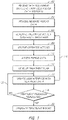
- Figure 1 shows a flowchart depicting an illustrative operation of the interactive treatment mapping and planning system. In various embodiments, fewer blocks or additional blocks may be included in the processes, or various blocks may be performed in an order different from that shown in Figure 1 . In an embodiment, one or more blocks in Figure 1 may be performed by, or implemented in, the interactive treatment mapping and planning system 800 shown in Figure 8 .
- various fibroid data may be optionally received by the system from a user input and/or one or more databases and/or data sources (including, for example, from databases maintained by the user or third party entities).
- the system may access fibroid data from one or more data sources.
- the data may comprise computer-readable output from a diagnostic test such as a transcervical uterine ultrasound, a laparoscopic ultrasound, or intrauterine ultrasound. The diagnostic test may be performed prior to or contemporaneously with the operation illustrated in Figure 1 .
- the data may then optionally be processed by the server at block 104.
- the fibroid data may be organized by location, type, and/or by any other useful index so as to enable fast searching of the fibroid data.
- a user interface (and/or user interface data) is generated that displays (and/or is useable to generate and display) a map interface, as described in further detail below.
- a map interface detailing a constructed fibroid map may be displayed on the user interface.
- the map interface may be constructed entirely automatically based on the received data, entirely by the user, or a combination thereof.
- the map interface may auto-populate based on the received data and then be manipulated by the user.
- the system creates a visual representation of fibroid data and/or treatment data on the generated user interface, including, for example, descriptions of the fibroids, fibroid locations, fibroid type (e.g., intramural, submucosal, subserosal, pedunculated submucosal, pedunculated subserosal), estimated fibroid sizes, fibroid prior treatment statuses, number of fibroids, fibroid treatment order, and other fibroid information
- the system may create a populated fibroid map following a preliminary exploratory procedure, as described below in reference to Figure 9 .
- the user may interact with the user interface of the system in any of the ways described below. For example, the user may import additional data, interact with the map interface, provide various search query criteria, etc.
- the fibroid data may be accessed by the system based on the provided user actions.
- the treatment system may access one or more internal and/or external databases in response to user actions. The one or more accessed internal and/or external databases may or may not include the fibroid data described above.
- the system may develop a treatment plan based on the constructed fibroid map.
- the treatment plan may be developed manually by the user.
- the system may develop the treatment plan automatically based on the fibroid data, as described in further detail below.
- the user may modify an automatically created treatment plan (e.g., changing the treatment order of the fibroids, selecting to skip treatment of some fibroids, etc.). Some changes may be prohibited or generate an error or warning message.
- the system may suggest changes to a manually created treatment plan.
- the user interface may be updated in response to the user's actions.
- the system may update the user interface following initiation of the treatment procedure.
- the updated interface may include data acquired from a treatment device.
- the user interface may display information regarding the treatment device(s), the treatment parameters, the day and/or time of treatment, and other treatment information described herein in further detail.
- Treatment may be prevented by the system unless the treatment can be linked to a specific fibroid.
- Fibroid information may be displayed in lists and/or in the map interface, and/or animations may be provided, among other interface updates described below.
- the operation may revert to block 108 such that the user may update and/or input a new action. After reversion, one or more of blocks 106, 108, 110, and/or 112 may be skipped.
- the system determines whether the treatment procedure has been terminated.
- the system may determine whether sufficient treatment has been performed prior to terminating the treatment procedure. In some embodiments, the system may not terminate the treatment procedure if the system determines that additional treatment is required. As indicated by arrow 120, if the treatment procedure has not terminated, the operation may continue to update the user interface as the user interacts with the system in any of the various ways described here. If the treatment procedure has terminated, the process proceeds to block 122.
- fibroid and/or treatment data may be received and processed by the system at any time and/or continuously.
- treatment data may be updated even as the user is viewing the data on the user interface.
- the user may use the system to analyze substantially real-time treatment data.
- the system may generate a report following the termination of the treatment procedure.
- the report may detail treatment information acquired during the treatment procedure.
- the report may include information regarding the fibroid(s), the treatment device, the treatment parameters, the day and/or time of treatment, etc. The report is described in further detail below.
- the system may generate alerts to the user.
- Alerts may comprise electronic notifications of changes and/or updates, for example, related to a user's actions.
- the system may determine new or different fibroid classification, or may determine that user interfaces are or would be updated as a result of the updates. Accordingly, in order that the user may be made aware of these changes in a timely manner, an alert and/or notification may be automatically transmitted, for example, to a device operated by the user.
- the alert and/or notification can be transmitted at the time that the alert and/or notification is generated or at some determined time after generation of the alert and/or notification.
- the alert and/or notification can cause the device to display the alert and/or notification via the activation of an application on the device.
- the device may comprise a browser, a mobile application, etc.
- receipt of the alert and/or notification may automatically activate an application on the device, such as a messaging application, a standalone application, or a browser, for example, and display information included in the alert and/or notification.
- the standalone application may comprise an interactive treatment mapping and planning system application.
- An alert may include notification that one or more fibroids was not treated, a treatment parameter may be inconsistent with the estimated fibroid size, there was a problem with the treatment device or a portion thereof (e.g., one or more thermocouples providing inconsistent data), etc.
- Embodiments of the disclosure will now be described with reference to the accompanying figures, wherein like numerals refer to like elements throughout.
- the terminology used in the description presented herein is not intended to be interpreted in any limited or restrictive manner, simply because it is being utilized in conjunction with a detailed description of certain specific embodiments of the disclosure.
- Embodiments of the disclosure may include several novel features, no single one of which is solely responsible for its desirable attributes or which is essential to practicing the embodiments of the disclosure herein described.
- Figures 2-5 illustrate an example of a graphical user interface 200 of the interactive treatment mapping and planning system.
- the user interface 200 may include an imaging field 202 displaying real-time images obtained from an ultrasound device or another imaging modality.
- the user interface 200 may further comprise a fibroid map interface 204 to assist a user before and/or during a treatment procedure.
- the fibroid map interface 204 may allow a user to obtain a comprehensive view of the mapped fibroids and develop a treatment plan prior to initiating a treatment procedure.
- the fibroid map interface 204 may be created using diagnostic images from an ultrasound device.
- the fibroid map interface 204 may be based on diagnostic data derived from other systems.
- the fibroid map interface 204 displays images or illustrations of a uterus.
- the fibroid map interface 204 displays several views of a uterus.
- the several views include a uterus front view 206 and/or a uterus side view 208.
- the uterus views 206, 208 may be annotated with directional indicators (e.g., left, right, lateral, medial, anterior, posterior, dorsal, ventral, inferior, superior) to orient a user interacting with the one or more uterus views 206, 208.
- a uterus front view 206 may indicate a right side and/or left side.
- a uterus side view 208 may indicate an anterior side and/or a posterior side.
- the fibroid map interface 204 may be located at various portions of the user interface 200.
- the fibroid map interface 204 may overlay a portion of the user interface 200 (e.g., as shown in Figures 2-5 ).
- the user may interact with the fibroid map interface 204 to resize the fibroid map interface 204 and/or move the fibroid map interface 204 throughout any portion of the user interface 200, for example to change obstruction of the view of the imaging field 202.
- the user interface 200 may comprise a separate viewing window or a split-screen window providing the fibroid map interface. In this case, the fibroid map interface 204 will not be displayed obstructing the imaging field 202.
- the user interface 200 and/or fibroid map interface 204 may further comprise several additional icons or buttons to increase the system's functionalities.
- the user interface 200 may comprise a fibroid map interface view button 210.
- the system may display the fibroid map interface 204.
- the system may subsequently remove the fibroid map interface 204 from view when the user again engages the view button 210.
- the fibroid map interface 204 may be removed from view when a user engages a fibroid map interface close button 212.
- the fibroid map interface may be removed from view or reduced in size upon user actions such as operation of a treatment device.
- the user interface 200 and or fibroid map interface 204 may further comprise a treatment report button 214 that, when engaged by the user, causes the system to generate a treatment report 600, 700, discussed in further detail below.
- functionality of the interactive treatment mapping and planning system may be implemented in one or more software computer modules stored in a memory and executed by one or more hardware processors, as is described below with reference to the example interactive treatment mapping and planning system 800 in Figure 8 .
- the system 800 can be designed to operate with the treatment device, display the user interface 200, and/or generate the treatment report 600, 700.
- the user interface 200 of Figures 2-5 may be displayed on an electronic display viewable by a user of the interactive treatment mapping and planning system.
- the user of the interactive treatment mapping and planning system may interact with the user interface 200 of Figures 2-5 by, for example, touching the display when the display is touch-enabled, using a mouse pointer to click on the various elements of the user interface 200, and/or using a keyboard to input data.
- the user of the system may interact with the user interface 200 by scrolling or panning up, down, and/or side to side; zooming in or out; selecting data items; drawing shapes; performing a search queries; and/or the like.
- Various user actions may reveal more or less user interface 200 and/or fibroid map interface 204 detail, and/or more or fewer data items.
- Figure 3 illustrates an example user interface 200 of the interactive treatment mapping and planning system in which various types of fibroid data items are displayed, according to block 106 of Figure 1 .
- the system utilizes the graphical fibroid map interface 204 to display visual representations that provide the user with insightful information about a mapped fibroid.
- the system displays a visual representation that provides the user with information relating to fibroid data, among other information, without the user having to go back to the one or more fibroid data source(s).
- the system Prior to initiation of a treatment procedure, receives fibroid data.
- a user may interact with the user interface 200 and/or fibroid map interface 204 to manually populate the fibroid map interface 204 with fibroid information.
- the user may review fibroid information based on previously gathered diagnostic results.
- the user may input the fibroid information into the user interface 200 and/or fibroid map interface 204.
- the system may automatically populate the fibroid map interface 200 with fibroid information.
- the system may generate fibroid information by aggregating information from a user and/or one or more separate data sources, discussed in further detail below with reference to Figure 9 .
- the system may automatically obtain fibroid data from single and/or multiple databases from which fibroid data may be obtained may be operated, maintained, and/or owned by various entities.
- the one or more databases may include a patient database and/or a hospital records management database.
- the system may track and record the fibroid information.
- Various data items may be represented on the fibroid map interface 204 with icons and/or symbols.
- Figures 2-5 illustrate several examples of fibroid icons 216 that may represent fibroid data on the uterus views 206, 208.
- the user may select and/or otherwise interact with fibroid data for each fibroid icon 216 displayed on the fibroid map interface 204.
- the system may display a fibroid icon 216 as a representation of fibroid data, including for example, a description of the fibroid, fibroid location, estimated fibroid size, fibroid prior treatment status, number of fibroids, fibroid treatment order, and other fibroid information.
- a user may manually populate the fibroid map interface 204 by interacting with a fibroid icon 216 within a fibroid icon selection tray 218.
- a user may interact with the system through various means. For example, the user may click and drag a fibroid icon 216 to a desired location. For another example, the user may click a fibroid icon 216 and subsequently click a desired location to place the fibroid icon 216 at the location. The user may click a desired location to place the fibroid icon 216 and subsequently click a fibroid icon 216 to place the fibroid icon 216 at the location.
- the system When a user places a fibroid icon 216 in one uterus view 206, 208, the system automaticahy populates the other uterus view 206, 208 with a fibroid icon 216 at the same location on the uterus. The user may alter the location of the fibroid icon 216 by interacting with the fibroid icon 216. In some embodiments, when a user moves a fibroid icon 216 up or down in a single uterus view 206, 208, the system may automatically move a corresponding fibroid icon 216 in another uterus view 206, 208.
- the system may not alter the location of a corresponding fibroid icon 216 in another uterus view 206, 208. This allows the fibroid icon 216 to maintain the representative horizontal location of the fibroid icon 216 on the fibroid map interface 204.
- each fibroid icon 216 may represent a fibroid type associated with a fibroid data item.
- the fibroid icon 216 may be chosen from a fibroid icon selection tray 218 based on the properties of the fibroid, as discussed in further detail below.
- the visual representation may be capable of quickly and efficiently providing the user with valuable fibroid information.
- the system may assign the particular representation to the fibroid data item based on fibroid information generated from the aggregated information.
- the visual representations of the fibroid icons 216 may be animated to show, among other things, recent activity, such as a change in fibroid treatment status, fibroid treatment order, or other fibroid information.
- the fibroid icon 216 may comprise different sizes to represent variations in the estimated fibroid size.
- the fibroid icon 216 may be selected from a large fibroid icon 216A, medium fibroid icon 216B, and small fibroid icon 216C displayed within the fibroid icon selection tray 218.
- the fibroid selection tray 218 may comprise a conical or frustoconical scale where a user can click along the longitudinal axis to select from an analog assortment of sizes.
- the fibroid selection tray 218 may prompt user input of a numerical fibroid estimated size and then base the fibroid icon 216 thereon.
- a fibroid icon 216 may provide a user with the ability to interact with the fibroid icon 216 to alter the properties of the fibroid icon 216. For example, a user may click and drag on a portion of the fibroid icon 216 to increase or decrease the size of the fibroid icon 216. This provides the user with the option to vary the fibroid icon 216 size to any representative fibroid size desired.
- Fibroid icons 216 may be circular/spherical (e.g., as shown in Figures 2-5 ) or oblong, elliptical, egg-shaped, or other shapes. In such embodiments, the fibroid icons 216 may be stretched, narrowed, rotated, etc.
- Fibroid icons 216 may be a graphical representation illustrating the relative fibroid size and fibroid location in a uterus.
- a fibroid map interface 204 may display various visual representations that provide the user with insightful information about the mapped fibroid(s).
- fibroid icon 217 indicates the presence of a large (216A-sized) fibroid located on the posterior side of the right wall of the uterine cavity.
- the fibroid icon 217 is yellow, which indicates that the fibroid is untreated.
- a white fibroid icon indicates that the fibroid has been treated.
- Other colors and schemes for indication of treatment are also possible.
- a grey-scale color scheme may be used to differentiate fibroid icons 216 indicating untreated and treated fibroids.
- the fibroid treatment status may be altered during and/or after a treatment procedure, as described below.
- Figure 3 also shows three other fibroids having various estimated sizes and locations.
- the user may select (e.g., by clicking on, hovering over, etc.), via the fibroid map interface 204, one or more of the fibroid icons 216 displayed to cause the system to display additional fibroid details.
- the additional information may be displayed in the fibroid map interface 204 or in a separate portion of the user interface 200.
- the user may further interact with a fibroid icon 216 to alter various other fibroid properties, such as fibroid treatment order (e.g., if the number indicates order of treatment, changing the number), fibroid treatment status (e.g., marking as treated), fibroid location (e.g., as described above), and/or other fibroid information.
- fibroid treatment order e.g., if the number indicates order of treatment, changing the number
- fibroid treatment status e.g., marking as treated
- fibroid location e.g., as described above
- the user interface 200 and/or fibroid map interface 204 may comprise a legend.
- Embodiments of the interactive treatment mapping and planning system relate to systems that facilitate the treatment of a fibroid.
- the fibroids described herein this specification may encompass any fibroid, and are not limited to a particular location or type of fibroid.
- the term fibroid is to be broadly construed and encompasses any abnormal tissue growth or any other superficial or other conditions or imperfections within the uterus of the patient or otherwise that benefit from ablation treatment.
- the term fibroid may be used herein to describe ectopic glandular tissue or myometrial found in the muscular wall of the uterus (adenomyosis or uterine endometriosis).
- the user may develop a treatment plan based on the fibroid map interface 204 following the construction of the fibroid map interface 204.
- the system may automatically develop a treatment plan based on the constructed fibroid map interface 204 and aggregated fibroid information.
- the treatment plan may comprise illustrating fibroid icons 216 on the fibroid map interface 204 to include numbering indicating a fibroid treatment order, as shown in Figures 3-5 .
- the user and/or system may alter the fibroid treatment order for a fibroid icon 216.
- An automated fibroid treatment order may be based on one or more parameters including, for example, fibroid size (e.g., largest to smallest, smallest to largest), fibroid location (e.g., most superior to most inferior, most inferior to most superior, most submucosal to most subserosal), likelihood of outgassing, ease of access, combinations thereof, and the like. Parameters may be provided with weighted scores to recommend, as a non-limiting example, treatment of a superior small submucosal fibroid before treatment of an inferior medium intramural fibroid.
- fibroid size e.g., largest to smallest, smallest to largest
- fibroid location e.g., most superior to most inferior, most inferior to most superior, most submucosal to most subserosal
- likelihood of outgassing ease of access, combinations thereof, and the like.
- Parameters may be provided with weighted scores to recommend, as a non-limiting example
- the treatment plan may target a fibroid(s) farthest from serosa prior to a fibroid(s) closest to serosa.
- the treatment plan may target pedunculated submucosal fibroid(s), submucosal fibroid(s), intramural fibroid(s), subserosal fibroid(s), and lastly pedunculated subserosal fibroid(s), in the order recited.
- the fibroid treatment order may be designed to avoid obscuring of the imaging field 202.
- Obscuring may arise through a process referred to as outgassing that occurs when steam created during ablation of a fibroid alters the quality of images produced by ultrasound or other imaging modalities.
- a treatment plan may be developed to avoid outgassing.
- Several factors may affect the extent to which outgassing occurs during the treatment procedure, such as the mapped fibroid location, the fibroid size, other fibroid information, treatment parameters (e.g., temperature, time, temperature ramping, etc.), etc.
- a treatment plan may be developed that treats fibroids located farther within a uterine cavity prior to treating fibroids located closer to the cervix.
- fibroids located closer to the cervix may be treated before fibroids located farther within the uterine cavity.
- a treatment plan may be developed to treat fibroids located closer to the surface of the uterine lining as opposed to fibroids located deeper within the uterine walls. Fibroid size may be a factor in determining fibroid treatment order.
- Embodiments of the interactive treatment planning and mapping system may utilize a combinatorial optimization algorithm to determine an improved or optimal fibroid treatment order subject to treatment constraints and/or treatment parameters (e.g., temperature, time, temperature ramping, reducing or avoiding outgassing, fibroid size, fibroid location, number of fibroids, etc.).
- treatment constraints and/or treatment parameters e.g., temperature, time, temperature ramping, reducing or avoiding outgassing, fibroid size, fibroid location, number of fibroids, etc.
- the imaging field 202, the fibroid map interface 204, or a combination of both may be utilized to determine placement and/or location of the treatment device during the treatment procedure.
- the interactive treatment planning and mapping system may determine placement and/or location of the treatment device based on fibroid data and treatment data. Several factors may affect the placement of the treatment device, such as the mapped fibroid location, the fibroid size, other fibroid information, treatment parameters (e.g., temperature, time, temperature ramping, etc.), and other information.
- the user interface may further comprise treatment device placement and/or location indications on the imaging field 202, the fibroid map interface 204, or a combination of both.
- the indications may instruct the user to place the treatment device in a particular position and/or location during the treatment procedure.
- Embodiments of the interactive treatment planning and mapping system may utilize a combinatorial optimization algorithm to determine an improved or optimal treatment device location and/or placement subject to treatment constraints and/or treatment parameters (e.g., temperature, time, temperature ramping, reducing or avoiding outgassing, fibroid size, fibroid location, number of fibroids, etc.).
- the treatment device may be configured to sense its position and/or orientation in space.
- the treatment device can transmit its position and/or orientation information to the interactive treatment planning and mapping system.
- the system may incorporate the position and/or orientation information into the imaging field 202, the fibroid map interface 204, or a combination of both to be displayed to a user.
- the treatment device may include one or more sensors to measure the position and/or orientation in three-dimensional space of the treatment device.
- the sensors may communicate the position and/or orientation information to the interactive treatment planning and mapping system, such that a position and/or orientation information of the treatment device can be displayed in the imaging field 202 and/or fibroid map interface 204.
- the treatment device is in the form of an ablation tool comprising a needle, but the treatment device can include other ablation and/or imaging devices, or may only include an imaging device (e.g., for diagnostic uses).
- the treatment device comprises one or more sensors configured to measure an insertion depth of the treatment device during a treatment procedure.
- the insertion depth can be communicated to the interactive treatment planning and mapping system such that depth of the treatment device can be displayed in the imaging field 202, the fibroid map interface 204, or a combination of both.
- the treatment device is configured to measure an insertion angle of the treatment device during a treatment procedure.
- the insertion angle information may be transmitted to the interactive treatment planning and mapping system to be displayed in the imaging field 202, the fibroid map interface 204, or a combination of both.
- the treatment device may include one or more sensors configured to determine a device position and/or orientation relative to other objects, such as, for example, a fibroid location, a user, one or more locations on a patient, combinations thereof, and the like.
- Information corresponding to the sensed position and/or orientation is transmitted to the interactive treatment planning and mapping system.
- Position and/or orientation information between the treatment device and a fibroid to be ablated may be captured by an external tracking system, such as, by way of non-limiting example, an optical tracking system.
- the tracking system can be configured to obtain at least one of position, orientation, and motion information of the treatment device used.
- the information sensed by the tracking system can be transmitted to the interactive treatment planning and mapping system.
- the system may be configured to receive the information and to display it in the imaging field 202, the fibroid map interface 204, or a combination of both.
- the position and/or orientation information may be determined by any suitable approaches to measure and determine the position and orientation of an object in three-dimensional space.
- an optical tracking system and/or inertial sensors for example, gyroscope sensors and/or accelerometers
- the treatment device may include visual markers that provide placement and/or location indications to a user.
- the treatment device may be annotated with positional indicators (e.g., depth indications) along at least a portion of the treatment device to orient a user interacting with the treatment device.
- positional indicators e.g., depth indications
- Indicators may be active (e.g., light-emitting diodes) and/or passive (e.g., optically recognizable patterns).
- the treatment device may comprise an alignment system that periodically emits a signal which is may be captured by one or more corresponding receivers.
- the one or more receivers may sense the signal from the treatment device directly.
- the alignment system may comprise a source of electromagnetic radiation and emit a signal comprising electromagnetic radiation.
- the source may be configured to transmit a signal that is capable of traveling through one or more portions of a patient anatomy to be received by a corresponding receiver located outside of a patient cavity.
- the position and/or orientation information transmitted to the interactive treatment planning and mapping system may be used in conjunction with fibroid data so that the locations of the treatment device in the imaging field 202 and/or the fibroid map interface 204 correspond to an actual location of the treatment device relative to one or more fibroids.
- the ability to obtain position and/or orientation data of the treatment device as the user is performing a treatment or diagnostic procedure can help the user perform a fibroid treatment at an optimal location.
- the interactive treatment planning and mapping system may instruct a user via the imaging field 202 and/or fibroid map interface 204 to guide the treatment device to an appropriate depth, position, and/or orientation for a therapeutic procedure.
- the movement of the treatment device can be projected on the imaging field 202 and/or fibroid map interface 204 in real-time during the treatment procedure. For example, as the treatment device is moved through a patient cavity, the location of a distal tip of the treatment device can be identified on the imaging field 202 and/or fibroid map interface 204. When the treatment device is positioned in a target location within the patient cavity, the treatment device may be positioned in the target location in the imaging field 202 and/or fibroid map interface 204.Updating A User Interface with Treatment Data
- the user interface 200 may be updated before and/or during a treatment procedure in response to the user's actions.
- the system may update the user interface 200 following initiation of the treatment procedure.
- the updated user interface 200 may include data acquired from the treatment devices, such as an ultrasound device and an ablation device.
- the user interface 200 may display information regarding the treatment device(s), the treatment parameters, the day and/or time of treatment, and other treatment information described herein in further detail.
- the fibroid map interface 204 may be updated to include treatment parameters 220.
- the displayed treatment parameters may comprise an ultrasound transducer angle relative to needle longitudinal axis ("Angle"), an ablation diameter along the minor axis ("Size”), needle deployment depth (“Intro”), electrode deployment length, and/or other treatment data.
- the user interface 200 may further comprise a treatment data interface 222 detailing the elapsed treatment time, treatment time remaining, ablation treatment volume, ablation treatment area, ablation time, ablation temperature, electrode and/or tissue impedance, radiofrequency power, radiofrequency temperature, and/or any other desired treatment data.
- the treatment data interface 222 may comprise a power graph 224 illustrating the relationship between time and radiofrequency power.
- the treatment data interface 222 may comprises a temperature graph 226 illustrating the relationship between time and mapped fibroid temperature.
- fibroid and/or treatment data may be received and processed by the system at any time and/or continuously.
- the system may determine whether the treatment procedure has been terminated. In some embodiments, termination can be determined by the user clicking the treatment report button 214 or the completed treatment of all mapped fibroids. If the treatment procedure has not been terminated, the system may continuously update the user interface 200 as the treatment procedure continues, as shown by arrow 120. In an embodiment, treatment data may be updated even as the user is viewing the data on the user interface 200. For example, the user may use the system to analyze substantially real-time treatment data through the treatment interface 222 and/or fibroid map interface 204.
- the system may provide color coded representations.
- the system may characterize a fibroid icon 216 into various classifications such as treatment status classifications: untreated, treated, previously treated but recurring fibroid, or untreated with a previous failed treatment attempt.
- the individual classifications may result in variations in the visual representation of the fibroid icon 216.
- color coded representation of fibroid icon 217T may indicate a treated fibroid
- fibroid icon 219U may represent an untreated fibroid.
- the user may interact with a fibroid classification before, during, and/or after a treatment procedure.
- a user may manually change a fibroid icon 216 to modify the treatment status of a fibroid icon 216 from "untreated” to “treated” after treating the fibroid.
- the system may automatically modify the fibroid icon's 216 treatment status based on treatment data received from the treatment device(s). The change in treatment status may automatically alter the visual representation of the fibroid icon 216 to properly indicate the updated fibroid treatment status.
- the classification of an untreated fibroid may initiate a warning or alert to the user relating to the fibroid.
- the fibroid icon 216 may change to a third color, have a treatment quantity indicator (e.g., "2"), combinations thereof, and the like.
- the system may automatically generate a treatment report 600, 700 following the termination of the treatment procedure, as shown in Figures 6-7 .
- a user may interact with the treatment report button 214 to instruct the system to generate a treatment report 600.
- the report 600 of Figure 6 may be generated by a user clicking the treatment report button 214 after treating the fibroid 217T at the time of Figure 4
- the report 700 of Figure 7 may be generated by a user clicking the treatment report button 214 after treating all of the fibroids at the time of Figure 5 .
- the treatment report 600, 700 may detail treatment information acquired during the treatment procedure.
- the treatment report 600, 700 may include information relating to fibroid location, estimated fibroid size, fibroid treated status, number of fibroids, fibroid treatment order, ultrasound device information (such as ultrasound device serial number), ultrasound transducer angle, ablation device information (such as ablation device serial number), needle deployment depth, electrode deployment length, planned fibroid size, ablation data, ablation data, ablation treatment volume, ablation treatment area, ablation time, ablation temperature, electrode and/or tissue impedance, radiofrequency power, radiofrequency temperature, time-temperature graphs, time-radiofrequency power graphs, ablation safety zone distance, photographs and/or screen shoots of the imaging field, treatment procedure information, time of treatment, treatment length, treatment date, patient data, attending physician and/or nurse, user and/or physician notes, and other fibroid and/or treatment information.
- Figure 6 illustrates an example treatment report 600.
- the treatment report 600 may include the fibroid map interface 204 along with an individual fibroid report 602.
- the treatment procedure may have been limited to a single fibroid.
- the treatment report 600 may include only one fibroid report 602.
- the report may include information about all mapped fibroids, only treated fibroids (e.g., as shown in Figure 6 ), or a subset of selected fibroids.
- the report may include a warning flag related to a fibroid (e.g., red text indicating a treatment time not commensurate with an estimated size).
- the treatment report 700 may include multiple fibroid reports 702, as shown in Figure 7 .
- the treatment report 600, 700 and/or fibroid report(s) 602, 702 may be exported to one or more databases.
- the system may export the report 600, 700 through wired and/or wireless connections.
- the interactive treatment mapping and planning system may incorporate a preliminary exploratory procedure.
- the system may enable a user to more efficiently aggregate fibroid information during an exploratory procedure, construct a fibroid map providing a visual representation of the aggregated fibroid information, and generate an exploratory report.
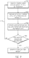
- Figure 9 shows a flowchart depicting an illustrative operation of the preliminary exploratory procedure.
- fewer blocks or additional blocks may be included in the processes, or various blocks may be performed in an order different from that shown in Figure 9 .
- one or more blocks in Figure 9 may be performed by, or implemented in, the interactive treatment mapping and planning system 800 shown in Figure 8 .
- various fibroid data may be identified during a preliminary exploratory procedure performed via a diagnostic test such as a transcervical uterine ultrasound, laparoscopic ultrasound, or intrauterine ultrasound.
- the system may receive the fibroid data from the imaging device(s) at block 904.
- diagnostic device placement and/or location data may be identified during a preliminary exploratory procedure.
- the interactive treatment mapping and planning system may utilize any structure, device, method, or features described herein in relation to the treatment device.
- the diagnostic device may include one or more sensors to measure the position and orientation in three-dimensional space of the diagnostic device.
- the diagnostic device can transmit its position and/or orientation information to the interactive treatment planning and mapping system.
- the system may incorporate the position and orientation information into a user interface to be displayed to a user. The method may end after such automated mapping.
- a user interface is generated that displays (and/or is useable to generate and display) a fibroid map interface similar to the user interface and fibroid map interface previously described above with reference to Figures 2-5 .
- the fibroid map interface may be constructed entirely automatically based on the received data, entirely by the user, or a combination thereof. For example, the map interface may auto-populate based on the received data and then be manipulated by the user.
- the system creates a visual representation of fibroid data on the generated user interface, including, for example, descriptions of the fibroids, fibroid locations, fibroid type (e.g., intramural, submucosal, subserosal, pedunculated submucosal, pedunculated subserosal), estimated fibroid sizes, fibroid prior treatment statuses, number of fibroids, fibroid treatment order, and other fibroid information.
- the system creates a visual representation of diagnostic device data on the generated user interface, including, for example, a position, orientation, motion, and/or other device information.
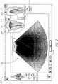
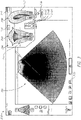
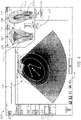
- Figures 10A-10D illustrate an example of a diagnostic device 1002 and a fibroid map interface 1004.
- the fibroid map interface 1004 may utilize any structure, device, method, or features described herein in relation to the interactive treatment mapping and planning system.
- the system may receive fibroid data from the diagnostic device 1002 to auto-populate the fibroid map interface 1004 with fibroid information.
- the diagnostic device 1002 may transmit fibroid information (e.g., fibroid location) to the system to input into the fibroid map interface 1004. Transmission of fibroid information may be based at least partially on sensor data (e.g., providing position and/or orientation information), for example in accordance with certain devices described herein.
- the system After locating a first fibroid, the system automatically populates the fibroid map interface 1004 with the fibroid information. For example, as illustrated in Figures 10A and 10B , the diagnostic device 1002 may identify fibroid 1 and transmit fibroid information to allow the system to display a fibroid icon 1 on the fibroid map interface 1004. In some embodiments, the diagnostic device 1002 may identify a plurality of fibroids and transmit a plurality of fibroid information to be displayed on the fibroid map interface 1004. Figures 10C and 10D illustrate that, in some instances, the diagnostic device 1002 may identify fibroid 2 and transmit fibroid information to allow the system to display a fibroid icon 2 on the fibroid map interface 1004. As described herein, the system may generate fibroid information by aggregating information from the diagnostic device.
- the system determines whether the exploratory procedure has terminated. As indicated by arrow 910, if the exploratory procedure has not terminated, the operation may continue to identify additional fibroid(s). For example, with reference to Figure 3 , the fibroid icon 217 may be generated on a first pass of blocks 902, 904, 906, 908, and then a second icon may be generated on a second pass blocks 902, 904, 906, 908, etc. At each block 906, fibroid icons from that pass and previous passes may be updated. If the exploratory procedure has terminated, the process proceeds to block 912.
- the system may automatically generate an exploratory report following the termination of the exploratory procedure.
- the report may detail exploratory information acquired during the exploratory procedure.
- the report may include information regarding the fibroid(s), the imaging device (e.g. an ultrasound transducer), the imaging parameters, the day and/or time of exploratory procedure, and other information.
- the exploratory report may include an automated and/or manual treatment protocol recommendation (e.g., labeling fibroid icons based on a recommended treatment order rather than the order in which the fibroids were diagnosed).
- the system may export a fibroid data file comprising the constructed fibroid map interface and/or exploratory report.
- the exploratory report may be readable to automatically populate a fibroid interface map 204.
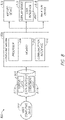
- FIG 8 is a block diagram that illustrates an example of an interactive treatment mapping and planning system 800 that can implement the various methods and functionality described herein (e.g., the operation methods described with reference to Figures 1 and 9 and the user interfaces 200 described with reference to Figures 2-5 , and the reports 600, 700 described with reference to Figures 6 and 7 ).
- an interactive treatment mapping and planning system 800 can implement the various methods and functionality described herein (e.g., the operation methods described with reference to Figures 1 and 9 and the user interfaces 200 described with reference to Figures 2-5 , and the reports 600, 700 described with reference to Figures 6 and 7 ).
- the interactive treatment mapping and planning system 800 may comprise an imaging device 814 (e.g. an ultrasound transducer or other imaging modality), a display device 816, and an ablation device 818 configured to generate radiofrequency energy for the treatment of an abnormal tissue growth.
- an imaging device 814 e.g. an ultrasound transducer or other imaging modality
- a display device 816 e.g. an IR transducer or other imaging modality
- an ablation device 818 configured to generate radiofrequency energy for the treatment of an abnormal tissue growth.
- the interactive treatment mapping and planning system 800 can include a computing engine 806, a data source 804, an imaging device 814, a display device 816, and an ablation device 818.
- the system 800 can receive user (e.g., physician) input from one or more user computing devices 802.
- the computing device(s) 802 may be any computing devices capable of displaying software applications to a user and receiving input from the user.
- the computing device(s) 802 may include smartphones, tablets, laptops, and/or other types of computing devices.
- the computing device(s) 852 may be capable of communicating over a network, for example, to request data from, and/or to provide data to, the components of the system 800.
- the data source 804 may include non-transitory computer-readable medium storage for storing fibroid data 811a and/or treatment data 811b.
- the computing engine 806 may perform a variety of tasks to implement the operations of the interactive treatment mapping and planning system.
- the computing engine 806 can include a hardware processor 808, a memory 810 (which can store code modules executed by the processor 808), and a communication interface 812 that communicates information to and/or from other components of the system 800.
- the computing engine 806 may include one or more software modules stored in the memory 810 and that, when executed by the processor 808, may, for example, receive fibroid data 811a and/or treatment data 811b from the data source 804, process the received data, generate user interfaces 200 and/or user interface data for display by the display device 816, process inputs from the user received from the computing device 802 or via the user interface (UI) 200 of the display device 816, and/or update the user interface 200.
- the processor 808 may be programmed to perform embodiments of the methods described with reference to Figures 1 and 9 .
- the computing engine 806 may be in communication with the data source 804.
- the database 804 may include electronic storage local to the computing engine 806.
- the data source 804 may be embodied in hard disk drives, solid state memories, and/or any other type of non-transitory, computer-readable storage medium remotely or locally accessible to the computing engine 806.
- the fibroid data 811a and/or the treatment data 811b may be distributed or partitioned across multiple storage devices, and/or may be combined into a single database.
- the computing engine 806 or data source 804 may be accessible by the user through a web-based viewer, such as a web browser, executed by the user computing device 802 or displayed as the display device 816.
- the display device 816 may be a computer monitor, a touchscreen, an electronic (e.g., LCD or LED) display, etc.
- the user interface may be generated by the computing engine 806 and transmitted to the web browser of the user computing device 802 or the display device 816.
- data necessary for generating the user interface 200 may be provided by the computing engine 806 to the display device 816, where the user interface may be generated for display.
- the user may interact with the user interface 200 through the web-browser or the display device 816.
- the user interface 200 of the interactive treatment mapping and planning system 800 may be accessible through a dedicated software application (rather than a web browser).
- the interactive treatment mapping and planning system 800 and other methods and techniques described herein can be implemented by one or more special-purpose computing devices such as the processor 808 and the memory 810.
- the special-purpose computing devices may be hard-wired to perform the techniques, or may include digital electronic devices such as one or more application-specific integrated circuits (ASICs) or field programmable gate arrays (FPGAs) that are persistently programmed to perform the techniques, or may include one or more general purpose hardware processors specially programmed to perform the techniques pursuant to program instructions in firmware, in executable code modules stored in the memory 810, other storage, or a combination.
- ASICs application-specific integrated circuits
- FPGAs field programmable gate arrays
- Such special-purpose computing devices may combine custom hard-wired logic, ASICs, or FPGAs with custom programming to accomplish the techniques.
- the special-purpose computing devices may be desktop computer systems, server computer systems, portable computer systems, handheld devices, networking devices or any other device or combination of devices that incorporate hard-wired and/or specialized program logic to implement the techniques described herein. Execution of the sequences of instructions contained in the memory 806 causes the processor(s) 804 to perform the process steps described herein.
- a phrase referring to "at least one of" a list of items refers to any combination of those items, including single members.
- "at least one of: A, B, or C” is intended to cover: A, B, C, A and B, A and C, B and C, and A, B, and C.
- Conjunctive language such as the phrase "at least one of X, Y and Z," unless specifically stated otherwise, is otherwise understood with the context as used in general to convey that an item, term, etc. may be at least one of X, Y or Z. Thus, such conjunctive language is not generally intended to imply that certain embodiments require at least one of X, at least one of Y and at least one of Z to each be present.
- the processes, methods, and systems may be implemented in a network (or distributed) computing environment.
- Network environments include enterprise-wide computer networks, intranets, local area networks (LAN), wide area networks (WAN), personal area networks (PAN), cloud computing networks, crowd-sourced computing networks, the Internet, and the World Wide Web.
- the network may be a wired or a wireless network or any other type of communication network.
- Code modules or any type of data may be stored on any type of non-transitory computer-readable medium, such as physical computer storage including hard drives, solid state memory, random access memory (RAM), read only memory (ROM), optical disc, volatile or non-volatile storage, combinations of the same and/or the like.
- the methods and modules (or data) may also be transmitted as generated data signals (e.g., as part of a carrier wave or other analog or digital propagated signal) on a variety of computer-readable transmission mediums, including wireless-based and wired/cable-based mediums, and may take a variety of forms (e.g., as part of a single or multiplexed analog signal, or as multiple discrete digital packets or frames).
- the results of the disclosed processes or process steps may be stored, persistently or otherwise, in any type of non-transitory, tangible computer storage or may be communicated via a computer-readable transmission medium.
Description
- The present disclosure relates generally to systems for controlling the deployment of needles through the construction of treatment maps. Embodiments of the present disclosure relate to systems and techniques for providing a user interface for dynamic interactions with fibroid data and treatment data. More specifically, examples of the present disclosure relate to user interfaces for dynamically providing a visual representation of information generated by aggregating treatment data from one or more medical articles and generating information.
- Current medical treatments of organs and tissues within a patient's body often use a needle or other elongate body for delivery of energy, therapeutic agents or the like. Some methods use ultrasound imaging to observe and identify a treatment target and predict and track the position of the needle relative to the treatment target.
- A treatment for uterine fibroids has recently been proposed which relies on the transvaginal or laparoscopic positioning of a treatment device in the patient's uterus. A radiofrequency or other energy or therapeutic delivery needle is deployed from the device into the fibroid, and energy and/or therapeutic substances are delivered in order to ablate or treat the fibroid. To facilitate locating the fibroids and positioning the needles within the fibroids, the device includes an ultrasonic imaging array with an adjustable field of view in a generally forward or lateral direction relative to an axial shaft which carries the needle. The needle is advanced from the shaft and across the field of view so that the needle can be visualized and directed into the tissue and the targeted fibroid.
-
US 2011/0087100 describes methods and devices for both imaging and treating uterine fibroid tumors in one real time system. One described minimally invasive method comprises introducing a sheath into a uterus and determining a location of a fibroid using a visualization element within or on the sheath. Upon identification, a portion of the sheath is steered to position at least one treatment needle at the determined location. The needle is then anchoring in uterine tissue and the fibroid treated with the needle. - The present invention is set out in the appended claims.
- The following drawings and the associated descriptions are provided to illustrate embodiments of the present disclosure. Aspects and many of the attendant advantages of this disclosure will become more readily appreciated as the same become better understood by reference to the following detailed description, when taken in conjunction with the accompanying drawings, wherein:
-
Figure 1 is a flowchart of an illustrative operation of an example interactive treatment mapping and planning system. -
Figure 2 illustrates an example graphical user interface of an interactive treatment mapping and planning system. -
Figure 3 illustrates an example graphical user interface with a constructed fibroid map located alongside a user interface of the interactive treatment mapping and planning system in which various types of fibroid icons are displayed with a representation of a uterus. -
Figure 4 illustrates an example graphical user interface of the interactive treatment mapping and planning system in which the fibroid map indicates that one fibroid has been treated. -
Figure 5 illustrates an example graphical user interface of the interactive treatment mapping and planning system in which the fibroid map indicates that all fibroids have been treated. -
Figure 6 illustrates an example of a treatment report that may be generated by the interactive treatment mapping and planning system in which a single fibroid has been treated. -
Figure 7 illustrates another example of a treatment report that may be generated by the interactive treatment mapping and planning system in which several fibroids have been treated. -
Figure 8 is a block diagram that illustrates an example interactive treatment mapping and planning system. -
Figure 9 is a flowchart of an illustrative operation of an example interactive treatment mapping and planning system. -
Figure 10A is an example diagnostic device of the interactive treatment mapping and planning system configured to identify fibroids within a uterus. -
Figure 10B illustrates an example of a fibroid map interface of the interactive treatment mapping and planning system in which various types of fibroid icons can be displayed with a representation of a uterus. -
Figure 10C is an example diagnostic device of the interactive treatment mapping and planning system configured to identify fibroids within a uterus. -
Figure 10D illustrates an example of a fibroid map interface of the interactive treatment mapping and planning system in which various types of fibroid icons can be displayed with a representation of a uterus. - The present disclosure provides improved systems and methods for the treatment of tissues such as uterine fibroids. The systems and methods allow the treating physician to interactively and efficiently access information to assist in the development of a treatment map and plan. Access to such information may facilitate the planning and treatment of targeted tissues and improve the likelihood that proper treatment of a targeted anatomy occurs. The systems and methods provide a user interface for real-time dynamic interactions and feedback regarding treatment data. Such information may allow the physician, if desired, to alter or reassess the treatment plan before and/or during the treatment procedure. The systems and methods provide user interfaces that can dynamically generate a visual representation of information by aggregating treatment data from one or more of the treatment devices and generating useful information.
- Feedback or other information is preferably provided visually on a treatment mapping and planning application. The treatment mapping and planning application may generally have graphical user interfaces that include real-time images overlaid by or alongside various objects and fibroid data. In some embodiments, the images may comprise ultrasonic or other imaging screens. An application may further be able to aggregate real-time information gathered from one or more treatment devices and display the information in an interactive manner that provides the user with information. For example, the real-time information may comprise feedback information in response to manipulating the probe and/or activating the needles. The system automatically aggregating the information reduces the need to enter data or commands onto a system controller or display, and can reduce the risk of data being lost altogether.
- The application may generate a treatment report including information regarding the fibroid(s), the treatment device, the treatment parameters, the day and/or time of treatment, and other treatment information.
- The structures, systems, and/or devices described herein may be embodied as integrated components or as separate components. For purposes of comparing various embodiments, certain aspects and advantages of these embodiments are described. Not necessarily all such aspects or advantages are achieved by any particular embodiment. Thus, for example, various embodiments may be carried out in a manner that achieves or optimizes one advantage or group of advantages as taught herein without necessarily achieving other aspects or advantages as may be taught or suggested herein.
- Unless otherwise noted, the systems and methods described herein may be used with any embodiment described and/or contemplated within
U.S. Patent Nos. 8,088,072 and8,992,427 . It will be understood that any of the embodiments described and/or contemplated withinU.S. Patent Nos. 8,088,072 and8,992,427 can be modified to be used with the systems and methods described herein. - An interactive treatment mapping and planning system enables a user to more quickly, thoroughly, and efficiently aggregate fibroid and/or treatment information from a user and/or data source, construct a fibroid map providing a visual representation of the aggregated fibroid information, generate information from the aggregated information about the fibroid to be treated and/or treatment procedure, develop a treatment plan based on the fibroid and/or treatment procedure information, provide real-time information gathered from treatment devices during the treatment procedure, and allow the user to interact with the treatment data. This and other functionality and advantages are provided via interactive graphical user interfaces, including interactive map interfaces, which are inextricably tied to computer technology.
- As mentioned above, the system enables a user to efficiently input and/or compile fibroid data, construct a fibroid map, develop a treatment plan, gather information regarding the treatment procedure, and generate a treatment report. The interactive treatment mapping and planning system may include an interactive user interface in which fibroid and/or treatment data may be displayed on a user interface.
- Fibroid data may refer to any type of data and/or information related to the fibroid(s) to be mapped. Fibroid data may also be referred to herein as fibroid data items. A fibroid data item generally includes at least a location associated with a fibroid. The location may be specified by, for example in some embodiments, a designated location selected by the user on a projected image located on or alongside a user interface. In some instances, fibroid data may include other information. For example, the fibroid data may comprise a description of the fibroid, fibroid location, fibroid type (e.g., intramural, submucosal, subserosal, pedunculated submucosal, pedunculated subserosal), estimated fibroid size, fibroid prior treatment status, number of fibroids, fibroid treatment order, and/or other fibroid information. Any combination of different types of fibroid data items may be used in the system simultaneously. Fibroid data items may be from various sources, and may be associated with various types of fibroids. Fibroid data may be obtained from a user, a single database, and/or multiple databases. The single and/or multiple databases from which fibroid data may be obtained may be operated, maintained, and/or owned by various entities. For example, the fibroid data may be obtained from a patient database and/or a hospital records management database.
- Treatment data may refer to any type of data and/or information related to the treatment procedure. Treatment data may also be referred to herein as treatment data items. A treatment data item generally includes at least information regarding the treatment device(s), the treatment parameters, the day and/or time of treatment, and/or other treatment information. In some instances treatment data may include other information. For example, the treatment data may comprise fibroid treatment order, treatment time, ultrasound device information (such as ultrasound device serial number), ultrasound transducer angle, ultrasound transducer position, ablation device information (such as ablation device serial number), needle deployment depth, electrode deployment length, ablation data, ablation treatment volume, ablation treatment area, ablation time, ablation temperature, electrode and/or tissue impedance, radiofrequency power, radiofrequency temperature, time-temperature graphs, time-radiofrequency power graphs, and/or other treatment information. Any combination of different types of treatment data items may be used in the system simultaneously. Treatment data items may be from various sources. Treatment data may be obtained from a user and/or treatment device(s) throughout a treatment procedure. For example, the treatment data may be obtained from various treatment devices, such as an ultrasound device and/or an ablation device.
-
Figure 1 shows a flowchart depicting an illustrative operation of the interactive treatment mapping and planning system. In various embodiments, fewer blocks or additional blocks may be included in the processes, or various blocks may be performed in an order different from that shown inFigure 1 . In an embodiment, one or more blocks inFigure 1 may be performed by, or implemented in, the interactive treatment mapping andplanning system 800 shown inFigure 8 . - At
block 102, various fibroid data may be optionally received by the system from a user input and/or one or more databases and/or data sources (including, for example, from databases maintained by the user or third party entities). As an example of the system receiving various fibroid data, the system may access fibroid data from one or more data sources. The data may comprise computer-readable output from a diagnostic test such as a transcervical uterine ultrasound, a laparoscopic ultrasound, or intrauterine ultrasound. The diagnostic test may be performed prior to or contemporaneously with the operation illustrated inFigure 1 . - The data may then optionally be processed by the server at
block 104. For example, the fibroid data may be organized by location, type, and/or by any other useful index so as to enable fast searching of the fibroid data. - At
block 106, a user interface (and/or user interface data) is generated that displays (and/or is useable to generate and display) a map interface, as described in further detail below. For example, a map interface detailing a constructed fibroid map, as described in further detail below, may be displayed on the user interface. The map interface may be constructed entirely automatically based on the received data, entirely by the user, or a combination thereof. For example, the map interface may auto-populate based on the received data and then be manipulated by the user. In various embodiments, the system creates a visual representation of fibroid data and/or treatment data on the generated user interface, including, for example, descriptions of the fibroids, fibroid locations, fibroid type (e.g., intramural, submucosal, subserosal, pedunculated submucosal, pedunculated subserosal), estimated fibroid sizes, fibroid prior treatment statuses, number of fibroids, fibroid treatment order, and other fibroid information In various embodiments, the system may create a populated fibroid map following a preliminary exploratory procedure, as described below in reference toFigure 9 . - At
block 108, the user may interact with the user interface of the system in any of the ways described below. For example, the user may import additional data, interact with the map interface, provide various search query criteria, etc. Atblock 110, the fibroid data may be accessed by the system based on the provided user actions. In various embodiments, the treatment system may access one or more internal and/or external databases in response to user actions. The one or more accessed internal and/or external databases may or may not include the fibroid data described above. - At
block 112, the system may develop a treatment plan based on the constructed fibroid map. The treatment plan may be developed manually by the user. In some embodiments, the system may develop the treatment plan automatically based on the fibroid data, as described in further detail below. The user may modify an automatically created treatment plan (e.g., changing the treatment order of the fibroids, selecting to skip treatment of some fibroids, etc.). Some changes may be prohibited or generate an error or warning message. The system may suggest changes to a manually created treatment plan. - At
block 114, the user interface may be updated in response to the user's actions. The system may update the user interface following initiation of the treatment procedure. The updated interface may include data acquired from a treatment device. For example, the user interface may display information regarding the treatment device(s), the treatment parameters, the day and/or time of treatment, and other treatment information described herein in further detail. Treatment may be prevented by the system unless the treatment can be linked to a specific fibroid. Fibroid information may be displayed in lists and/or in the map interface, and/or animations may be provided, among other interface updates described below. As indicated byarrow 116, the operation may revert to block 108 such that the user may update and/or input a new action. After reversion, one or more ofblocks - At
block 118, the system determines whether the treatment procedure has been terminated. The system may determine whether sufficient treatment has been performed prior to terminating the treatment procedure. In some embodiments, the system may not terminate the treatment procedure if the system determines that additional treatment is required. As indicated byarrow 120, if the treatment procedure has not terminated, the operation may continue to update the user interface as the user interacts with the system in any of the various ways described here. If the treatment procedure has terminated, the process proceeds to block 122. - In various embodiments, fibroid and/or treatment data may be received and processed by the system at any time and/or continuously. In an embodiment, treatment data may be updated even as the user is viewing the data on the user interface. For example, the user may use the system to analyze substantially real-time treatment data.
- At
block 122, the system may generate a report following the termination of the treatment procedure. The report may detail treatment information acquired during the treatment procedure. For example, the report may include information regarding the fibroid(s), the treatment device, the treatment parameters, the day and/or time of treatment, etc. The report is described in further detail below. - The system may generate alerts to the user. Alerts may comprise electronic notifications of changes and/or updates, for example, related to a user's actions. For example, as treatment data is updated in the system, the system may determine new or different fibroid classification, or may determine that user interfaces are or would be updated as a result of the updates. Accordingly, in order that the user may be made aware of these changes in a timely manner, an alert and/or notification may be automatically transmitted, for example, to a device operated by the user. The alert and/or notification can be transmitted at the time that the alert and/or notification is generated or at some determined time after generation of the alert and/or notification. When received by the device, the alert and/or notification can cause the device to display the alert and/or notification via the activation of an application on the device. In some embodiments, the device may comprise a browser, a mobile application, etc. For example, receipt of the alert and/or notification may automatically activate an application on the device, such as a messaging application, a standalone application, or a browser, for example, and display information included in the alert and/or notification. In some embodiments, the standalone application may comprise an interactive treatment mapping and planning system application. An alert may include notification that one or more fibroids was not treated, a treatment parameter may be inconsistent with the estimated fibroid size, there was a problem with the treatment device or a portion thereof (e.g., one or more thermocouples providing inconsistent data), etc.
- Embodiments of the disclosure will now be described with reference to the accompanying figures, wherein like numerals refer to like elements throughout. The terminology used in the description presented herein is not intended to be interpreted in any limited or restrictive manner, simply because it is being utilized in conjunction with a detailed description of certain specific embodiments of the disclosure. Embodiments of the disclosure may include several novel features, no single one of which is solely responsible for its desirable attributes or which is essential to practicing the embodiments of the disclosure herein described.
-
Figures 2-5 illustrate an example of agraphical user interface 200 of the interactive treatment mapping and planning system. Theuser interface 200 may include animaging field 202 displaying real-time images obtained from an ultrasound device or another imaging modality. Theuser interface 200 may further comprise afibroid map interface 204 to assist a user before and/or during a treatment procedure. Thefibroid map interface 204 may allow a user to obtain a comprehensive view of the mapped fibroids and develop a treatment plan prior to initiating a treatment procedure. Thefibroid map interface 204 may be created using diagnostic images from an ultrasound device. Thefibroid map interface 204 may be based on diagnostic data derived from other systems. Thefibroid map interface 204 displays images or illustrations of a uterus. Thefibroid map interface 204 displays several views of a uterus.. As shown inFigures 2-5 , the several views include auterus front view 206 and/or auterus side view 208. The uterus views 206, 208 may be annotated with directional indicators (e.g., left, right, lateral, medial, anterior, posterior, dorsal, ventral, inferior, superior) to orient a user interacting with the one or more uterus views 206, 208. For example, auterus front view 206 may indicate a right side and/or left side. For another example, auterus side view 208 may indicate an anterior side and/or a posterior side. - The
fibroid map interface 204 may be located at various portions of theuser interface 200. In some embodiments, thefibroid map interface 204 may overlay a portion of the user interface 200 (e.g., as shown inFigures 2-5 ). The user may interact with thefibroid map interface 204 to resize thefibroid map interface 204 and/or move thefibroid map interface 204 throughout any portion of theuser interface 200, for example to change obstruction of the view of theimaging field 202. In some embodiments, theuser interface 200 may comprise a separate viewing window or a split-screen window providing the fibroid map interface. In this case, thefibroid map interface 204 will not be displayed obstructing theimaging field 202. - The
user interface 200 and/orfibroid map interface 204 may further comprise several additional icons or buttons to increase the system's functionalities. In some embodiments, theuser interface 200 may comprise a fibroid mapinterface view button 210. When a user engages theview button 210, the system may display thefibroid map interface 204. The system may subsequently remove thefibroid map interface 204 from view when the user again engages theview button 210. In some embodiments, thefibroid map interface 204 may be removed from view when a user engages a fibroid map interfaceclose button 212. In some embodiments, the fibroid map interface may be removed from view or reduced in size upon user actions such as operation of a treatment device. - The
user interface 200 and orfibroid map interface 204 may further comprise atreatment report button 214 that, when engaged by the user, causes the system to generate atreatment report - In various embodiments, functionality of the interactive treatment mapping and planning system (as described in reference to the various figures below) may be implemented in one or more software computer modules stored in a memory and executed by one or more hardware processors, as is described below with reference to the example interactive treatment mapping and
planning system 800 inFigure 8 . Thesystem 800 can be designed to operate with the treatment device, display theuser interface 200, and/or generate thetreatment report - In various embodiments, the
user interface 200 ofFigures 2-5 may be displayed on an electronic display viewable by a user of the interactive treatment mapping and planning system. The user of the interactive treatment mapping and planning system may interact with theuser interface 200 ofFigures 2-5 by, for example, touching the display when the display is touch-enabled, using a mouse pointer to click on the various elements of theuser interface 200, and/or using a keyboard to input data. - The user of the system may interact with the
user interface 200 by scrolling or panning up, down, and/or side to side; zooming in or out; selecting data items; drawing shapes; performing a search queries; and/or the like. Various user actions may reveal more orless user interface 200 and/orfibroid map interface 204 detail, and/or more or fewer data items. -
Figure 3 illustrates anexample user interface 200 of the interactive treatment mapping and planning system in which various types of fibroid data items are displayed, according to block 106 ofFigure 1 . In some embodiments, the system utilizes the graphicalfibroid map interface 204 to display visual representations that provide the user with insightful information about a mapped fibroid. In some embodiments, the system displays a visual representation that provides the user with information relating to fibroid data, among other information, without the user having to go back to the one or more fibroid data source(s). - Prior to initiation of a treatment procedure, the system receives fibroid data. In some embodiments, a user may interact with the
user interface 200 and/orfibroid map interface 204 to manually populate thefibroid map interface 204 with fibroid information. The user may review fibroid information based on previously gathered diagnostic results. After locating one or more fibroids through a preliminary ultrasound or other imaging modality exploratory procedure, the user may input the fibroid information into theuser interface 200 and/orfibroid map interface 204. The system may automatically populate thefibroid map interface 200 with fibroid information. During the preliminary exploratory procedure, the system may generate fibroid information by aggregating information from a user and/or one or more separate data sources, discussed in further detail below with reference toFigure 9 . In some embodiments, as described above, the system may automatically obtain fibroid data from single and/or multiple databases from which fibroid data may be obtained may be operated, maintained, and/or owned by various entities. The one or more databases may include a patient database and/or a hospital records management database. Following input of the fibroid information, either manually by the user or automatically by the system, the system may track and record the fibroid information. - Various data items, including fibroid data items, may be represented on the
fibroid map interface 204 with icons and/or symbols.Figures 2-5 illustrate several examples offibroid icons 216 that may represent fibroid data on the uterus views 206, 208. The user may select and/or otherwise interact with fibroid data for eachfibroid icon 216 displayed on thefibroid map interface 204. In various embodiments, the system may display afibroid icon 216 as a representation of fibroid data, including for example, a description of the fibroid, fibroid location, estimated fibroid size, fibroid prior treatment status, number of fibroids, fibroid treatment order, and other fibroid information. - A user may manually populate the
fibroid map interface 204 by interacting with afibroid icon 216 within a fibroidicon selection tray 218. As discussed above, a user may interact with the system through various means. For example, the user may click and drag afibroid icon 216 to a desired location. For another example, the user may click afibroid icon 216 and subsequently click a desired location to place thefibroid icon 216 at the location. The user may click a desired location to place thefibroid icon 216 and subsequently click afibroid icon 216 to place thefibroid icon 216 at the location. When a user places afibroid icon 216 in oneuterus view other uterus view fibroid icon 216 at the same location on the uterus. The user may alter the location of thefibroid icon 216 by interacting with thefibroid icon 216. In some embodiments, when a user moves afibroid icon 216 up or down in asingle uterus view corresponding fibroid icon 216 in anotheruterus view fibroid icon 216 left or right in asingle uterus view corresponding fibroid icon 216 in anotheruterus view fibroid icon 216 to maintain the representative horizontal location of thefibroid icon 216 on thefibroid map interface 204. - In various embodiments, the system displays each
fibroid icon 216 on thefibroid map interface 204 through a particular visual representation. Eachfibroid icon 216 may represent a fibroid type associated with a fibroid data item. Thefibroid icon 216 may be chosen from a fibroidicon selection tray 218 based on the properties of the fibroid, as discussed in further detail below. The visual representation may be capable of quickly and efficiently providing the user with valuable fibroid information. The system may assign the particular representation to the fibroid data item based on fibroid information generated from the aggregated information. The visual representations of thefibroid icons 216 may be animated to show, among other things, recent activity, such as a change in fibroid treatment status, fibroid treatment order, or other fibroid information. - The
fibroid icon 216 may comprise different sizes to represent variations in the estimated fibroid size. For example, as shown inFigure 3 , thefibroid icon 216 may be selected from alarge fibroid icon 216A,medium fibroid icon 216B, andsmall fibroid icon 216C displayed within the fibroidicon selection tray 218. Thefibroid selection tray 218 may comprise a conical or frustoconical scale where a user can click along the longitudinal axis to select from an analog assortment of sizes. Thefibroid selection tray 218 may prompt user input of a numerical fibroid estimated size and then base thefibroid icon 216 thereon. Afibroid icon 216 may provide a user with the ability to interact with thefibroid icon 216 to alter the properties of thefibroid icon 216. For example, a user may click and drag on a portion of thefibroid icon 216 to increase or decrease the size of thefibroid icon 216. This provides the user with the option to vary thefibroid icon 216 size to any representative fibroid size desired.Fibroid icons 216 may be circular/spherical (e.g., as shown inFigures 2-5 ) or oblong, elliptical, egg-shaped, or other shapes. In such embodiments, thefibroid icons 216 may be stretched, narrowed, rotated, etc. The user may alter the properties of thefibroid icon 216 prior to and/or after thefibroid icon 216 is placed on thefibroid map interface 204.Fibroid icons 216 may be a graphical representation illustrating the relative fibroid size and fibroid location in a uterus. - As shown in
Figure 3 , afibroid map interface 204 may display various visual representations that provide the user with insightful information about the mapped fibroid(s). For example,fibroid icon 217 indicates the presence of a large (216A-sized) fibroid located on the posterior side of the right wall of the uterine cavity. Thefibroid icon 217 is yellow, which indicates that the fibroid is untreated. As shown inFigures 4 and5 , a white fibroid icon indicates that the fibroid has been treated. Other colors and schemes for indication of treatment are also possible. For example, a grey-scale color scheme may be used to differentiatefibroid icons 216 indicating untreated and treated fibroids. The fibroid treatment status may be altered during and/or after a treatment procedure, as described below.Figure 3 also shows three other fibroids having various estimated sizes and locations. - In some embodiments, the user may select (e.g., by clicking on, hovering over, etc.), via the
fibroid map interface 204, one or more of thefibroid icons 216 displayed to cause the system to display additional fibroid details. The additional information may be displayed in thefibroid map interface 204 or in a separate portion of theuser interface 200. These capabilities can increase user efficiency by granting the user access to fibroid data through theuser interface 200. - In some embodiments, the user may further interact with a
fibroid icon 216 to alter various other fibroid properties, such as fibroid treatment order (e.g., if the number indicates order of treatment, changing the number), fibroid treatment status (e.g., marking as treated), fibroid location (e.g., as described above), and/or other fibroid information. - In some embodiments, the
user interface 200 and/orfibroid map interface 204 may comprise a legend. - Embodiments of the interactive treatment mapping and planning system relate to systems that facilitate the treatment of a fibroid. It will be understood by one of skill in the art that the fibroids described herein this specification may encompass any fibroid, and are not limited to a particular location or type of fibroid. It is to be understood that the term fibroid is to be broadly construed and encompasses any abnormal tissue growth or any other superficial or other conditions or imperfections within the uterus of the patient or otherwise that benefit from ablation treatment. For example, the term fibroid may be used herein to describe ectopic glandular tissue or myometrial found in the muscular wall of the uterus (adenomyosis or uterine endometriosis).
- At
block 112 ofFigure 1 , the user may develop a treatment plan based on thefibroid map interface 204 following the construction of thefibroid map interface 204. In alternative embodiments, the system may automatically develop a treatment plan based on the constructedfibroid map interface 204 and aggregated fibroid information. The treatment plan may comprise illustratingfibroid icons 216 on thefibroid map interface 204 to include numbering indicating a fibroid treatment order, as shown inFigures 3-5 . The user and/or system may alter the fibroid treatment order for afibroid icon 216. An automated fibroid treatment order may be based on one or more parameters including, for example, fibroid size (e.g., largest to smallest, smallest to largest), fibroid location (e.g., most superior to most inferior, most inferior to most superior, most submucosal to most subserosal), likelihood of outgassing, ease of access, combinations thereof, and the like. Parameters may be provided with weighted scores to recommend, as a non-limiting example, treatment of a superior small submucosal fibroid before treatment of an inferior medium intramural fibroid. - The treatment plan may target a fibroid(s) farthest from serosa prior to a fibroid(s) closest to serosa. The treatment plan may target pedunculated submucosal fibroid(s), submucosal fibroid(s), intramural fibroid(s), subserosal fibroid(s), and lastly pedunculated subserosal fibroid(s), in the order recited.
- In some embodiments, the fibroid treatment order may be designed to avoid obscuring of the
imaging field 202. Obscuring may arise through a process referred to as outgassing that occurs when steam created during ablation of a fibroid alters the quality of images produced by ultrasound or other imaging modalities. As such, a treatment plan may be developed to avoid outgassing. Several factors may affect the extent to which outgassing occurs during the treatment procedure, such as the mapped fibroid location, the fibroid size, other fibroid information, treatment parameters (e.g., temperature, time, temperature ramping, etc.), etc. In some embodiments, a treatment plan may be developed that treats fibroids located farther within a uterine cavity prior to treating fibroids located closer to the cervix. Alternatively, fibroids located closer to the cervix may be treated before fibroids located farther within the uterine cavity. A treatment plan may be developed to treat fibroids located closer to the surface of the uterine lining as opposed to fibroids located deeper within the uterine walls. Fibroid size may be a factor in determining fibroid treatment order. Embodiments of the interactive treatment planning and mapping system may utilize a combinatorial optimization algorithm to determine an improved or optimal fibroid treatment order subject to treatment constraints and/or treatment parameters (e.g., temperature, time, temperature ramping, reducing or avoiding outgassing, fibroid size, fibroid location, number of fibroids, etc.). - In some embodiments, the
imaging field 202, thefibroid map interface 204, or a combination of both may be utilized to determine placement and/or location of the treatment device during the treatment procedure. The interactive treatment planning and mapping system may determine placement and/or location of the treatment device based on fibroid data and treatment data. Several factors may affect the placement of the treatment device, such as the mapped fibroid location, the fibroid size, other fibroid information, treatment parameters (e.g., temperature, time, temperature ramping, etc.), and other information. The user interface may further comprise treatment device placement and/or location indications on theimaging field 202, thefibroid map interface 204, or a combination of both. The indications may instruct the user to place the treatment device in a particular position and/or location during the treatment procedure. Embodiments of the interactive treatment planning and mapping system may utilize a combinatorial optimization algorithm to determine an improved or optimal treatment device location and/or placement subject to treatment constraints and/or treatment parameters (e.g., temperature, time, temperature ramping, reducing or avoiding outgassing, fibroid size, fibroid location, number of fibroids, etc.). - The treatment device, in some instances, may be configured to sense its position and/or orientation in space. The treatment device can transmit its position and/or orientation information to the interactive treatment planning and mapping system. The system may incorporate the position and/or orientation information into the
imaging field 202, thefibroid map interface 204, or a combination of both to be displayed to a user. The treatment device may include one or more sensors to measure the position and/or orientation in three-dimensional space of the treatment device. The sensors may communicate the position and/or orientation information to the interactive treatment planning and mapping system, such that a position and/or orientation information of the treatment device can be displayed in theimaging field 202 and/orfibroid map interface 204. In some instances, the treatment device is in the form of an ablation tool comprising a needle, but the treatment device can include other ablation and/or imaging devices, or may only include an imaging device (e.g., for diagnostic uses). - In some embodiments, the treatment device comprises one or more sensors configured to measure an insertion depth of the treatment device during a treatment procedure. The insertion depth can be communicated to the interactive treatment planning and mapping system such that depth of the treatment device can be displayed in the
imaging field 202, thefibroid map interface 204, or a combination of both. In some instances, the treatment device is configured to measure an insertion angle of the treatment device during a treatment procedure. The insertion angle information may be transmitted to the interactive treatment planning and mapping system to be displayed in theimaging field 202, thefibroid map interface 204, or a combination of both. - In some embodiments, the treatment device may include one or more sensors configured to determine a device position and/or orientation relative to other objects, such as, for example, a fibroid location, a user, one or more locations on a patient, combinations thereof, and the like. Information corresponding to the sensed position and/or orientation is transmitted to the interactive treatment planning and mapping system. Position and/or orientation information between the treatment device and a fibroid to be ablated may be captured by an external tracking system, such as, by way of non-limiting example, an optical tracking system. The tracking system can be configured to obtain at least one of position, orientation, and motion information of the treatment device used. The information sensed by the tracking system can be transmitted to the interactive treatment planning and mapping system. The system may be configured to receive the information and to display it in the
imaging field 202, thefibroid map interface 204, or a combination of both. The position and/or orientation information may be determined by any suitable approaches to measure and determine the position and orientation of an object in three-dimensional space. For example, an optical tracking system and/or inertial sensors (for example, gyroscope sensors and/or accelerometers) can be configured to obtain one or more of position, orientation, and motion information of the treatment device. In some instances, the treatment device may include visual markers that provide placement and/or location indications to a user. For example, the treatment device may be annotated with positional indicators (e.g., depth indications) along at least a portion of the treatment device to orient a user interacting with the treatment device. Indicators may be active (e.g., light-emitting diodes) and/or passive (e.g., optically recognizable patterns). - In some implementations, the treatment device may comprise an alignment system that periodically emits a signal which is may be captured by one or more corresponding receivers. In some embodiments, the one or more receivers may sense the signal from the treatment device directly. The alignment system may comprise a source of electromagnetic radiation and emit a signal comprising electromagnetic radiation. For example, the source may be configured to transmit a signal that is capable of traveling through one or more portions of a patient anatomy to be received by a corresponding receiver located outside of a patient cavity.
- The position and/or orientation information transmitted to the interactive treatment planning and mapping system may be used in conjunction with fibroid data so that the locations of the treatment device in the
imaging field 202 and/or thefibroid map interface 204 correspond to an actual location of the treatment device relative to one or more fibroids. The ability to obtain position and/or orientation data of the treatment device as the user is performing a treatment or diagnostic procedure can help the user perform a fibroid treatment at an optimal location. For example, during a treatment procedure, the interactive treatment planning and mapping system may instruct a user via theimaging field 202 and/orfibroid map interface 204 to guide the treatment device to an appropriate depth, position, and/or orientation for a therapeutic procedure. In some instances, the movement of the treatment device can be projected on theimaging field 202 and/orfibroid map interface 204 in real-time during the treatment procedure. For example, as the treatment device is moved through a patient cavity, the location of a distal tip of the treatment device can be identified on theimaging field 202 and/orfibroid map interface 204. When the treatment device is positioned in a target location within the patient cavity, the treatment device may be positioned in the target location in theimaging field 202 and/or fibroid map interface 204.Updating A User Interface with Treatment Data - At
block 114 shown inFigure 1 , theuser interface 200 may be updated before and/or during a treatment procedure in response to the user's actions. In some embodiments, the system may update theuser interface 200 following initiation of the treatment procedure. The updateduser interface 200 may include data acquired from the treatment devices, such as an ultrasound device and an ablation device. For example, as discussed above, theuser interface 200 may display information regarding the treatment device(s), the treatment parameters, the day and/or time of treatment, and other treatment information described herein in further detail. In some embodiments, as shown inFigures 4-5 , thefibroid map interface 204 may be updated to includetreatment parameters 220. The displayed treatment parameters may comprise an ultrasound transducer angle relative to needle longitudinal axis ("Angle"), an ablation diameter along the minor axis ("Size"), needle deployment depth ("Intro"), electrode deployment length, and/or other treatment data. - The
user interface 200 may further comprise atreatment data interface 222 detailing the elapsed treatment time, treatment time remaining, ablation treatment volume, ablation treatment area, ablation time, ablation temperature, electrode and/or tissue impedance, radiofrequency power, radiofrequency temperature, and/or any other desired treatment data. In some embodiments, thetreatment data interface 222 may comprise a power graph 224 illustrating the relationship between time and radiofrequency power. Thetreatment data interface 222 may comprises a temperature graph 226 illustrating the relationship between time and mapped fibroid temperature. - In various embodiments, fibroid and/or treatment data may be received and processed by the system at any time and/or continuously. As indicated by
block 118 inFigure 1 , the system may determine whether the treatment procedure has been terminated. In some embodiments, termination can be determined by the user clicking thetreatment report button 214 or the completed treatment of all mapped fibroids. If the treatment procedure has not been terminated, the system may continuously update theuser interface 200 as the treatment procedure continues, as shown byarrow 120. In an embodiment, treatment data may be updated even as the user is viewing the data on theuser interface 200. For example, the user may use the system to analyze substantially real-time treatment data through thetreatment interface 222 and/orfibroid map interface 204. - In various embodiments, the system may provide color coded representations. For example, the system may characterize a
fibroid icon 216 into various classifications such as treatment status classifications: untreated, treated, previously treated but recurring fibroid, or untreated with a previous failed treatment attempt. The individual classifications may result in variations in the visual representation of thefibroid icon 216. For example, as shown inFigure 4 , color coded representation offibroid icon 217T may indicate a treated fibroid, while fibroid icon 219U may represent an untreated fibroid. The user may interact with a fibroid classification before, during, and/or after a treatment procedure. In some embodiments, a user may manually change afibroid icon 216 to modify the treatment status of afibroid icon 216 from "untreated" to "treated" after treating the fibroid. Alternatively, the system may automatically modify the fibroid icon's 216 treatment status based on treatment data received from the treatment device(s). The change in treatment status may automatically alter the visual representation of thefibroid icon 216 to properly indicate the updated fibroid treatment status. In some embodiments, the classification of an untreated fibroid may initiate a warning or alert to the user relating to the fibroid. If a fibroid is treated for a second time, for example because a first treatment was not able to capture the entire fibroid or the portion of the fibroid to be treated, thefibroid icon 216 may change to a third color, have a treatment quantity indicator (e.g., "2"), combinations thereof, and the like. - As discussed previously, at
block 122 inFigure 1 , the system may automatically generate atreatment report Figures 6-7 . A user may interact with thetreatment report button 214 to instruct the system to generate atreatment report 600. For example, thereport 600 ofFigure 6 may be generated by a user clicking thetreatment report button 214 after treating thefibroid 217T at the time ofFigure 4 , and thereport 700 ofFigure 7 may be generated by a user clicking thetreatment report button 214 after treating all of the fibroids at the time ofFigure 5 . - The
treatment report treatment report -
Figure 6 illustrates anexample treatment report 600. In some embodiments, thetreatment report 600 may include thefibroid map interface 204 along with anindividual fibroid report 602. For example, as shown inFigure 6 , the treatment procedure may have been limited to a single fibroid. In this instance, thetreatment report 600 may include only onefibroid report 602. The report may include information about all mapped fibroids, only treated fibroids (e.g., as shown inFigure 6 ), or a subset of selected fibroids. The report may include a warning flag related to a fibroid (e.g., red text indicating a treatment time not commensurate with an estimated size). Thetreatment report 700 may include multiplefibroid reports 702, as shown inFigure 7 . - In some embodiments, the
treatment report report - The interactive treatment mapping and planning system may incorporate a preliminary exploratory procedure. The system may enable a user to more efficiently aggregate fibroid information during an exploratory procedure, construct a fibroid map providing a visual representation of the aggregated fibroid information, and generate an exploratory report.
-
Figure 9 shows a flowchart depicting an illustrative operation of the preliminary exploratory procedure. In various embodiments, fewer blocks or additional blocks may be included in the processes, or various blocks may be performed in an order different from that shown inFigure 9 . In an embodiment, one or more blocks inFigure 9 may be performed by, or implemented in, the interactive treatment mapping andplanning system 800 shown inFigure 8 . - At
block 902, various fibroid data may be identified during a preliminary exploratory procedure performed via a diagnostic test such as a transcervical uterine ultrasound, laparoscopic ultrasound, or intrauterine ultrasound. The system may receive the fibroid data from the imaging device(s) atblock 904. - In some instances, at
block 902, diagnostic device placement and/or location data may be identified during a preliminary exploratory procedure. The interactive treatment mapping and planning system may utilize any structure, device, method, or features described herein in relation to the treatment device. For example, the diagnostic device may include one or more sensors to measure the position and orientation in three-dimensional space of the diagnostic device. The diagnostic device can transmit its position and/or orientation information to the interactive treatment planning and mapping system. The system may incorporate the position and orientation information into a user interface to be displayed to a user. The method may end after such automated mapping. - At
block 906, a user interface is generated that displays (and/or is useable to generate and display) a fibroid map interface similar to the user interface and fibroid map interface previously described above with reference toFigures 2-5 . The fibroid map interface may be constructed entirely automatically based on the received data, entirely by the user, or a combination thereof. For example, the map interface may auto-populate based on the received data and then be manipulated by the user. In various embodiments, the system creates a visual representation of fibroid data on the generated user interface, including, for example, descriptions of the fibroids, fibroid locations, fibroid type (e.g., intramural, submucosal, subserosal, pedunculated submucosal, pedunculated subserosal), estimated fibroid sizes, fibroid prior treatment statuses, number of fibroids, fibroid treatment order, and other fibroid information. In some embodiments, the system creates a visual representation of diagnostic device data on the generated user interface, including, for example, a position, orientation, motion, and/or other device information. -
Figures 10A-10D illustrate an example of adiagnostic device 1002 and afibroid map interface 1004. Thefibroid map interface 1004 may utilize any structure, device, method, or features described herein in relation to the interactive treatment mapping and planning system. In some instances, the system may receive fibroid data from thediagnostic device 1002 to auto-populate thefibroid map interface 1004 with fibroid information. Through an exploratory procedure, thediagnostic device 1002 may transmit fibroid information (e.g., fibroid location) to the system to input into thefibroid map interface 1004. Transmission of fibroid information may be based at least partially on sensor data (e.g., providing position and/or orientation information), for example in accordance with certain devices described herein. After locating a first fibroid, the system automatically populates thefibroid map interface 1004 with the fibroid information. For example, as illustrated inFigures 10A and 10B , thediagnostic device 1002 may identifyfibroid 1 and transmit fibroid information to allow the system to display afibroid icon 1 on thefibroid map interface 1004. In some embodiments, thediagnostic device 1002 may identify a plurality of fibroids and transmit a plurality of fibroid information to be displayed on thefibroid map interface 1004.Figures 10C and 10D illustrate that, in some instances, thediagnostic device 1002 may identifyfibroid 2 and transmit fibroid information to allow the system to display afibroid icon 2 on thefibroid map interface 1004. As described herein, the system may generate fibroid information by aggregating information from the diagnostic device. - At
block 908, the system determines whether the exploratory procedure has terminated. As indicated byarrow 910, if the exploratory procedure has not terminated, the operation may continue to identify additional fibroid(s). For example, with reference toFigure 3 , thefibroid icon 217 may be generated on a first pass ofblocks block 906, fibroid icons from that pass and previous passes may be updated. If the exploratory procedure has terminated, the process proceeds to block 912. - At
block 912, the system may automatically generate an exploratory report following the termination of the exploratory procedure. The report may detail exploratory information acquired during the exploratory procedure. For example, the report may include information regarding the fibroid(s), the imaging device (e.g. an ultrasound transducer), the imaging parameters, the day and/or time of exploratory procedure, and other information. The exploratory report may include an automated and/or manual treatment protocol recommendation (e.g., labeling fibroid icons based on a recommended treatment order rather than the order in which the fibroids were diagnosed). - In various embodiments, the system may export a fibroid data file comprising the constructed fibroid map interface and/or exploratory report. The exploratory report may be readable to automatically populate a
fibroid interface map 204. -
Figure 8 is a block diagram that illustrates an example of an interactive treatment mapping andplanning system 800 that can implement the various methods and functionality described herein (e.g., the operation methods described with reference toFigures 1 and9 and theuser interfaces 200 described with reference toFigures 2-5 , and thereports Figures 6 and7 ). - As previously discussed, the interactive treatment mapping and
planning system 800 may comprise an imaging device 814 (e.g. an ultrasound transducer or other imaging modality), adisplay device 816, and anablation device 818 configured to generate radiofrequency energy for the treatment of an abnormal tissue growth. - The interactive treatment mapping and
planning system 800 can include acomputing engine 806, adata source 804, animaging device 814, adisplay device 816, and anablation device 818. Thesystem 800 can receive user (e.g., physician) input from one or moreuser computing devices 802. In an embodiment, the computing device(s) 802 may be any computing devices capable of displaying software applications to a user and receiving input from the user. For example, the computing device(s) 802 may include smartphones, tablets, laptops, and/or other types of computing devices. The computing device(s) 852 may be capable of communicating over a network, for example, to request data from, and/or to provide data to, the components of thesystem 800. In some embodiments, thedata source 804 may include non-transitory computer-readable medium storage for storingfibroid data 811a and/or treatment data 811b. - The
computing engine 806 may perform a variety of tasks to implement the operations of the interactive treatment mapping and planning system. Thecomputing engine 806 can include ahardware processor 808, a memory 810 (which can store code modules executed by the processor 808), and acommunication interface 812 that communicates information to and/or from other components of thesystem 800. - The
computing engine 806 may include one or more software modules stored in thememory 810 and that, when executed by theprocessor 808, may, for example, receivefibroid data 811a and/or treatment data 811b from thedata source 804, process the received data, generateuser interfaces 200 and/or user interface data for display by thedisplay device 816, process inputs from the user received from thecomputing device 802 or via the user interface (UI) 200 of thedisplay device 816, and/or update theuser interface 200. Theprocessor 808 may be programmed to perform embodiments of the methods described with reference toFigures 1 and9 . - The
computing engine 806 may be in communication with thedata source 804. Thedatabase 804 may include electronic storage local to thecomputing engine 806. Thedata source 804 may be embodied in hard disk drives, solid state memories, and/or any other type of non-transitory, computer-readable storage medium remotely or locally accessible to thecomputing engine 806. Thefibroid data 811a and/or the treatment data 811b may be distributed or partitioned across multiple storage devices, and/or may be combined into a single database. - In various embodiments, the
computing engine 806 or data source 804may be accessible by the user through a web-based viewer, such as a web browser, executed by theuser computing device 802 or displayed as thedisplay device 816. Thedisplay device 816 may be a computer monitor, a touchscreen, an electronic (e.g., LCD or LED) display, etc. The user interface may be generated by thecomputing engine 806 and transmitted to the web browser of theuser computing device 802 or thedisplay device 816. Alternatively, data necessary for generating theuser interface 200 may be provided by thecomputing engine 806 to thedisplay device 816, where the user interface may be generated for display. The user may interact with theuser interface 200 through the web-browser or thedisplay device 816. In an embodiment, theuser interface 200 of the interactive treatment mapping andplanning system 800 may be accessible through a dedicated software application (rather than a web browser). - The interactive treatment mapping and
planning system 800 and other methods and techniques described herein can be implemented by one or more special-purpose computing devices such as theprocessor 808 and thememory 810. The special-purpose computing devices may be hard-wired to perform the techniques, or may include digital electronic devices such as one or more application-specific integrated circuits (ASICs) or field programmable gate arrays (FPGAs) that are persistently programmed to perform the techniques, or may include one or more general purpose hardware processors specially programmed to perform the techniques pursuant to program instructions in firmware, in executable code modules stored in thememory 810, other storage, or a combination. Such special-purpose computing devices may combine custom hard-wired logic, ASICs, or FPGAs with custom programming to accomplish the techniques. The special-purpose computing devices may be desktop computer systems, server computer systems, portable computer systems, handheld devices, networking devices or any other device or combination of devices that incorporate hard-wired and/or specialized program logic to implement the techniques described herein. Execution of the sequences of instructions contained in thememory 806 causes the processor(s) 804 to perform the process steps described herein. - Each of the processes, methods, and algorithms described in the preceding sections may be embodied in, and fully or partially automated by, code modules stored in memory and executed by one or more computer systems or computer processors comprising computer hardware. The processes and algorithms may be implemented partially or wholly in application-specific circuitry.
- The various features and processes described above may be used independently of one another, or may be combined in various ways. In addition, certain method or process blocks may be omitted in some implementations. The methods and processes described herein are not limited to any particular sequence, and the blocks or states relating thereto can be performed in other sequences that are appropriate. For example, described blocks or states may be performed in an order other than that specifically disclosed, or multiple blocks or states may be combined in a single block or state. The example blocks or states may be performed in serial, in parallel, or in some other manner. Blocks or states may be added to or removed from the disclosed example embodiments. The example systems and components described herein may be configured differently than described. For example, elements may be added to, removed from, or rearranged compared to the disclosed example embodiments.
- Conditional language, such as, among others, "can," "could," "might," or "may," unless specifically stated otherwise, or otherwise understood within the context as used, is generally intended to convey that certain embodiments include, while other embodiments do not include, certain features, elements and/or steps. Thus, such conditional language is not generally intended to imply that features, elements and/or steps are in any way required for one or more embodiments or that one or more embodiments necessarily include logic for deciding, with or without user input or prompting, whether these features, elements and/or steps are included or are to be performed in any particular embodiment.
- The term "comprising" as used herein should be given an inclusive rather than exclusive interpretation. For example, a general purpose computer comprising one or more processors should not be interpreted as excluding other computer components, and may possibly include such components as non-transitory memory, input/output devices, and/or network interfaces, among others. Also, the term "or" is used in its inclusive sense (and not in its exclusive sense) so that when used, for example, to connect a list of elements, the term "or" means one, some, or all of the elements in the list. In addition, the articles "a," "an," and "the" as used in this application and the appended claims are to be construed to mean "one or more" or "at least one" unless specified otherwise.
- As used herein, a phrase referring to "at least one of" a list of items refers to any combination of those items, including single members. As an example, "at least one of: A, B, or C" is intended to cover: A, B, C, A and B, A and C, B and C, and A, B, and C. Conjunctive language such as the phrase "at least one of X, Y and Z," unless specifically stated otherwise, is otherwise understood with the context as used in general to convey that an item, term, etc. may be at least one of X, Y or Z. Thus, such conjunctive language is not generally intended to imply that certain embodiments require at least one of X, at least one of Y and at least one of Z to each be present.
- The processes, methods, and systems may be implemented in a network (or distributed) computing environment. Network environments include enterprise-wide computer networks, intranets, local area networks (LAN), wide area networks (WAN), personal area networks (PAN), cloud computing networks, crowd-sourced computing networks, the Internet, and the World Wide Web. The network may be a wired or a wireless network or any other type of communication network.
- Any process descriptions, elements, or blocks in the flow diagrams described herein and/or depicted in the attached figures should be understood as potentially representing modules, segments, or portions of code which include one or more executable instructions for implementing specific logical functions or steps in the process. Alternate implementations are included within the scope of the embodiments described herein in which elements or functions may be deleted, executed out of order from that shown or discussed, including substantially concurrently or in reverse order, depending on the functionality involved, as would be understood by those skilled in the art.
- Code modules or any type of data may be stored on any type of non-transitory computer-readable medium, such as physical computer storage including hard drives, solid state memory, random access memory (RAM), read only memory (ROM), optical disc, volatile or non-volatile storage, combinations of the same and/or the like. The methods and modules (or data) may also be transmitted as generated data signals (e.g., as part of a carrier wave or other analog or digital propagated signal) on a variety of computer-readable transmission mediums, including wireless-based and wired/cable-based mediums, and may take a variety of forms (e.g., as part of a single or multiplexed analog signal, or as multiple discrete digital packets or frames). The results of the disclosed processes or process steps may be stored, persistently or otherwise, in any type of non-transitory, tangible computer storage or may be communicated via a computer-readable transmission medium.
- The ranges disclosed herein also encompass any and all overlap, sub-ranges, and combinations thereof. Language such as "up to," "at least," "greater than," "less than," "between," and the like includes the number recited. Numbers preceded by a term such as "about" or "approximately" include the recited numbers and should be interpreted based on the circumstances (e.g., as accurate as reasonably possible under the circumstances, for example ±5%, ±10%, ±15%, etc.). For example, "about 1" includes "1." Phrases preceded by a term such as "substantially," "generally," and the like include the recited phrase and should be interpreted based on the circumstances (e.g., as much as reasonably possible under the circumstances). For example, "substantially spherical" includes "spherical." Unless stated otherwise, all measurements are at standard conditions including temperature and pressure.
Claims (15)
- A system comprising:a non-transitory computer readable storage medium configured to store program instructions; anda processor programmed to execute the program instructions to cause the processor to:aggregate, from one or more data sources, a plurality of fibroid data records;extract, from the plurality of fibroid data records, fibroid data record items; andgenerate user interface data for rendering an interactive user interface on an electronic display, the interactive user interface including:a fibroid map interface (204) displaying several views of a uterus including a uterus front view (206) and a uterus side view (208), anda visual representation of a fibroid data record item, the visual representation comprising a fibroid icon (216) on the fibroid map interface (204) at a location associated with the fibroid data item, the visual representation configured to provide information relating to the fibroid data record item, characterized in that when a user places a fibroid icon (216) in one uterus view (206, 208) the system automatically populates the other uterus view (206, 208) with another fibroid icon (216) at the same location on the uterus.
- The system of Claim 1, wherein the location of the fibroid icon comprises a graphical representation of a fibroid location in a uterus of a patient.
- The system of Claim 1 or 2, wherein the processor is programmed to aggregate a plurality of fibroid data records from at least one of:an input from a user;a user data source; ora third party data source.
- The system of any one of Claims 1-3, wherein the fibroid data record item comprises at least one of a fibroid location, a fibroid size, a fibroid treatment status, a number of fibroids, and a fibroid treatment order.
- The system of Claim 3, wherein the input from the user comprises at least one of:user fibroid data record items; ortreatment data record items.
- The system of Claim 5, wherein the processor is programmed, in response to the user input, to:update the one or more data sources with the user fibroid data record item; andupdate the user interface data such that the interactive user interface includes an indication of at least one of the user fibroid data record items.
- The system of any one of Claims 1-6, wherein the processor is programmed to receive user input, and wherein the user input includes export criteria comprising at least one of:an export content;an export format; oran export location.
- The system of Claim 7, wherein the processor is programmed, in response to the user input, to:extract, from the fibroid data records, fibroid data export items relating to the export content;generate an export document comprising the export format and the fibroid data export items;store the export document at the export location; andupdate the user interface data such that the interactive user interface includes an indication of the export request.
- The system of any one of Claims 1-8, wherein the interactive user interface further comprises a legend.
- The system of any one of Claims 1-9, wherein the visual representation is configured to indicate a warning to the user.
- The system of any one of Claims 1-10, wherein the processor is programmed to:identify a fibroid using an information from an imaging modality;receive fibroid data from the imaging modality; andgenerate an exploratory report.
- The system of any one of Claims 1-11, wherein the processor is programmed to:receive fibroid data from a one or more data sources;receive treatment data from a treatment device; andupdate the user interface with treatment data.
- The system of Claim 12, wherein the processor is further programmed to generate a treatment report.
- The system of any one of Claims 1-13, wherein the processor is programmed so that, when a user moves the fibroid icon up or down in one uterus view, the system automatically moves the other fibroid icon in the other uterus view.
- The system of any one of Claims 1-14, wherein the processor is programmed so that, when a user moves the fibroid icon left or right in one uterus view, the system does not alter the location of the other fibroid icon in the other uterus view.
Priority Applications (1)
| Application Number | Priority Date | Filing Date | Title |
|---|---|---|---|
| EP22192376.6A EP4156204A1 (en) | 2016-11-11 | 2017-11-08 | Controlled treatment of tissue and dynamic interaction with, and comparison of, tissue and/or treatment data |
Applications Claiming Priority (2)
| Application Number | Priority Date | Filing Date | Title |
|---|---|---|---|
| US201662421119P | 2016-11-11 | 2016-11-11 | |
| PCT/US2017/060674 WO2018089523A1 (en) | 2016-11-11 | 2017-11-08 | Controlled treatment of tissue and dynamic interaction with, and comparison of, tissue and/or treatment data |
Related Child Applications (1)
| Application Number | Title | Priority Date | Filing Date |
|---|---|---|---|
| EP22192376.6A Division EP4156204A1 (en) | 2016-11-11 | 2017-11-08 | Controlled treatment of tissue and dynamic interaction with, and comparison of, tissue and/or treatment data |
Publications (3)
| Publication Number | Publication Date |
|---|---|
| EP3537982A1 EP3537982A1 (en) | 2019-09-18 |
| EP3537982A4 EP3537982A4 (en) | 2020-07-01 |
| EP3537982B1 true EP3537982B1 (en) | 2022-09-07 |
Family
ID=62110340
Family Applications (2)
| Application Number | Title | Priority Date | Filing Date |
|---|---|---|---|
| EP22192376.6A Pending EP4156204A1 (en) | 2016-11-11 | 2017-11-08 | Controlled treatment of tissue and dynamic interaction with, and comparison of, tissue and/or treatment data |
| EP17870547.1A Active EP3537982B1 (en) | 2016-11-11 | 2017-11-08 | Controlled treatment of tissue and dynamic interaction with tissue and/or treatment data and comparison of tissue and/or treatment data |
Family Applications Before (1)
| Application Number | Title | Priority Date | Filing Date |
|---|---|---|---|
| EP22192376.6A Pending EP4156204A1 (en) | 2016-11-11 | 2017-11-08 | Controlled treatment of tissue and dynamic interaction with, and comparison of, tissue and/or treatment data |
Country Status (9)
| Country | Link |
|---|---|
| US (3) | US10993770B2 (en) |
| EP (2) | EP4156204A1 (en) |
| JP (2) | JP7237829B2 (en) |
| KR (1) | KR20190095922A (en) |
| CN (2) | CN115715689A (en) |
| AU (2) | AU2017359338B2 (en) |
| CA (1) | CA3043314A1 (en) |
| ES (1) | ES2927968T3 (en) |
| WO (1) | WO2018089523A1 (en) |
Families Citing this family (5)
| Publication number | Priority date | Publication date | Assignee | Title |
|---|---|---|---|---|
| US11227427B2 (en) * | 2014-08-11 | 2022-01-18 | Covidien Lp | Treatment procedure planning system and method |
| AU2017359338B2 (en) | 2016-11-11 | 2022-09-08 | Gynesonics, Inc. | Controlled treatment of tissue and dynamic interaction with, and comparison of, tissue and/or treatment data |
| EP3843650A4 (en) * | 2018-08-27 | 2022-05-18 | Nesa Medtech | A system and method for the ablation of uterine fibroids |
| CN116669635A (en) * | 2020-10-27 | 2023-08-29 | 杰尼索尼克斯公司 | Systems and methods for image-guided tissue ablation |
| KR102412618B1 (en) * | 2020-11-18 | 2022-06-23 | 가톨릭대학교 산학협력단 | Method and device for analyzing cervicography image |
Family Cites Families (375)
| Publication number | Priority date | Publication date | Assignee | Title |
|---|---|---|---|---|
| US4289132A (en) | 1979-06-25 | 1981-09-15 | Rieman Robert D | Surgical instrument and method of using the same |
| US4272955A (en) | 1979-06-28 | 1981-06-16 | General Electric Company | Diffusing means |
| US5370675A (en) | 1992-08-12 | 1994-12-06 | Vidamed, Inc. | Medical probe device and method |
| US4567896A (en) | 1984-01-20 | 1986-02-04 | Elscint, Inc. | Method and apparatus for calibrating a biopsy attachment for ultrasonic imaging apparatus |
| US4671292A (en) | 1985-04-30 | 1987-06-09 | Dymax Corporation | Concentric biopsy probe |
| US5000185A (en) | 1986-02-28 | 1991-03-19 | Cardiovascular Imaging Systems, Inc. | Method for intravascular two-dimensional ultrasonography and recanalization |
| US4742829A (en) | 1986-08-11 | 1988-05-10 | General Electric Company | Intracavitary ultrasound and biopsy probe for transvaginal imaging |
| EP0273180B1 (en) | 1986-12-05 | 1991-06-12 | Siemens Aktiengesellschaft | Intracavitary ultrasonic scanning apparatus |
| US4802487A (en) | 1987-03-26 | 1989-02-07 | Washington Research Foundation | Endoscopically deliverable ultrasound imaging system |
| US5269301A (en) | 1987-10-06 | 1993-12-14 | Leonard Bloom | Multimode system for monitoring and treating a malfunctioning heart |
| US5372138A (en) | 1988-03-21 | 1994-12-13 | Boston Scientific Corporation | Acousting imaging catheters and the like |
| JPH0255050A (en) | 1988-08-22 | 1990-02-23 | Toshiba Corp | Mechanical scanning type ultrasonic probe |
| US5372587A (en) | 1989-01-09 | 1994-12-13 | Pilot Cariovascular Systems, Inc. | Steerable medical device |
| US4936281A (en) | 1989-04-13 | 1990-06-26 | Everest Medical Corporation | Ultrasonically enhanced RF ablation catheter |
| US5316000A (en) | 1991-03-05 | 1994-05-31 | Technomed International (Societe Anonyme) | Use of at least one composite piezoelectric transducer in the manufacture of an ultrasonic therapy apparatus for applying therapy, in a body zone, in particular to concretions, to tissue, or to bones, of a living being and method of ultrasonic therapy |
| US6485413B1 (en) | 1991-04-29 | 2002-11-26 | The General Hospital Corporation | Methods and apparatus for forward-directed optical scanning instruments |
| US6730081B1 (en) | 1991-10-18 | 2004-05-04 | Ashvin H. Desai | Endoscopic surgical instrument |
| US6461296B1 (en) | 1998-06-26 | 2002-10-08 | 2000 Injectx, Inc. | Method and apparatus for delivery of genes, enzymes and biological agents to tissue cells |
| US7549424B2 (en) | 1991-10-18 | 2009-06-23 | Pro Surg, Inc. | Method and apparatus for tissue treatment with laser and electromagnetic radiation |
| US5190050A (en) | 1991-11-08 | 1993-03-02 | Electro-Catheter Corporation | Tip deflectable steerable catheter |
| US6024733A (en) | 1995-06-07 | 2000-02-15 | Arthrocare Corporation | System and method for epidermal tissue ablation |
| US6770071B2 (en) | 1995-06-07 | 2004-08-03 | Arthrocare Corporation | Bladed electrosurgical probe |
| DE4209425C1 (en) | 1992-03-24 | 1993-09-02 | Markus 73563 Moegglingen De Dubberke | |
| US5470308A (en) | 1992-08-12 | 1995-11-28 | Vidamed, Inc. | Medical probe with biopsy stylet |
| US5364408A (en) | 1992-09-04 | 1994-11-15 | Laurus Medical Corporation | Endoscopic suture system |
| US5335663A (en) | 1992-12-11 | 1994-08-09 | Tetrad Corporation | Laparoscopic probes and probe sheaths useful in ultrasonic imaging applications |
| US5469853A (en) | 1992-12-11 | 1995-11-28 | Tetrad Corporation | Bendable ultrasonic probe and sheath for use therewith |
| US6832996B2 (en) | 1995-06-07 | 2004-12-21 | Arthrocare Corporation | Electrosurgical systems and methods for treating tissue |
| US5860974A (en) | 1993-07-01 | 1999-01-19 | Boston Scientific Corporation | Heart ablation catheter with expandable electrode and method of coupling energy to an electrode on a catheter shaft |
| US5456689A (en) | 1993-10-13 | 1995-10-10 | Arnold J. Kresch | Method and device for tissue resection |
| US5599345A (en) | 1993-11-08 | 1997-02-04 | Zomed International, Inc. | RF treatment apparatus |
| US6569159B1 (en) | 1993-11-08 | 2003-05-27 | Rita Medical Systems, Inc. | Cell necrosis apparatus |
| US5474075A (en) | 1993-11-24 | 1995-12-12 | Thomas Jefferson University | Brush-tipped catheter for ultrasound imaging |
| US6241725B1 (en) | 1993-12-15 | 2001-06-05 | Sherwood Services Ag | High frequency thermal ablation of cancerous tumors and functional targets with image data assistance |
| US5471988A (en) | 1993-12-24 | 1995-12-05 | Olympus Optical Co., Ltd. | Ultrasonic diagnosis and therapy system in which focusing point of therapeutic ultrasonic wave is locked at predetermined position within observation ultrasonic scanning range |
| DE4443947B4 (en) | 1994-01-14 | 2005-09-22 | Siemens Ag | endoscope |
| US5873828A (en) | 1994-02-18 | 1999-02-23 | Olympus Optical Co., Ltd. | Ultrasonic diagnosis and treatment system |
| US5517989A (en) | 1994-04-01 | 1996-05-21 | Cardiometrics, Inc. | Guidewire assembly |
| US5492126A (en) | 1994-05-02 | 1996-02-20 | Focal Surgery | Probe for medical imaging and therapy using ultrasound |
| JP3419884B2 (en) | 1994-05-11 | 2003-06-23 | オリンパス光学工業株式会社 | Control system |
| US6002968A (en) | 1994-06-24 | 1999-12-14 | Vidacare, Inc. | Uterine treatment apparatus |
| US6405732B1 (en) | 1994-06-24 | 2002-06-18 | Curon Medical, Inc. | Method to treat gastric reflux via the detection and ablation of gastro-esophageal nerves and receptors |
| US6032673A (en) | 1994-10-13 | 2000-03-07 | Femrx, Inc. | Methods and devices for tissue removal |
| EP0889706A1 (en) | 1995-03-08 | 1999-01-13 | TERWILLIGER, Richard, A. | Echogenic needle |
| US6083169A (en) | 1995-04-19 | 2000-07-04 | B & K Ultrasound Systems A/S | Method and an apparatus for the insertion of a needle guide into a patient in order to remove tissue samples |
| US6575969B1 (en) | 1995-05-04 | 2003-06-10 | Sherwood Services Ag | Cool-tip radiofrequency thermosurgery electrode system for tumor ablation |
| US5979452A (en) | 1995-06-07 | 1999-11-09 | General Surgical Innovations, Inc. | Endoscopic linton procedure using balloon dissectors and retractors |
| US6837888B2 (en) | 1995-06-07 | 2005-01-04 | Arthrocare Corporation | Electrosurgical probe with movable return electrode and methods related thereto |
| US6632193B1 (en) | 1995-06-07 | 2003-10-14 | Arthrocare Corporation | Systems and methods for electrosurgical tissue treatment |
| US5964740A (en) | 1996-07-09 | 1999-10-12 | Asahi Kogaku Kogyo Kabushiki Kaisha | Treatment accessory for an endoscope |
| US6837887B2 (en) | 1995-06-07 | 2005-01-04 | Arthrocare Corporation | Articulated electrosurgical probe and methods |
| US5590658A (en) | 1995-06-29 | 1997-01-07 | Teratech Corporation | Portable ultrasound imaging system |
| US5964709A (en) | 1995-06-29 | 1999-10-12 | Teratech Corporation | Portable ultrasound imaging system |
| CA2225784A1 (en) | 1995-06-30 | 1997-01-23 | Boston Scientific Corporation | Ultrasound imaging catheter with a cutting element |
| EP0845959A4 (en) | 1995-07-16 | 1998-09-30 | Ultra Guide Ltd | Free-hand aiming of a needle guide |
| US6256529B1 (en) | 1995-07-26 | 2001-07-03 | Burdette Medical Systems, Inc. | Virtual reality 3D visualization for surgical procedures |
| US6080150A (en) | 1995-08-15 | 2000-06-27 | Rita Medical Systems, Inc. | Cell necrosis apparatus |
| US6375615B1 (en) | 1995-10-13 | 2002-04-23 | Transvascular, Inc. | Tissue penetrating catheters having integral imaging transducers and their methods of use |
| US5979453A (en) | 1995-11-09 | 1999-11-09 | Femrx, Inc. | Needle myolysis system for uterine fibriods |
| US5780435A (en) | 1995-12-15 | 1998-07-14 | Praecis Pharmaceuticals Incorporated | Methods for treating prostate cancer with LHRH-R antagonists |
| US5863294A (en) | 1996-01-26 | 1999-01-26 | Femrx, Inc. | Folded-end surgical tubular cutter and method for fabrication |
| US6203524B1 (en) | 1997-02-10 | 2001-03-20 | Emx, Inc. | Surgical and pharmaceutical site access guide and methods |
| US6813520B2 (en) | 1996-04-12 | 2004-11-02 | Novacept | Method for ablating and/or coagulating tissue using moisture transport |
| US5769880A (en) | 1996-04-12 | 1998-06-23 | Novacept | Moisture transport system for contact electrocoagulation |
| US6077257A (en) | 1996-05-06 | 2000-06-20 | Vidacare, Inc. | Ablation of rectal and other internal body structures |
| US6419673B1 (en) | 1996-05-06 | 2002-07-16 | Stuart Edwards | Ablation of rectal and other internal body structures |
| US5649911A (en) | 1996-05-17 | 1997-07-22 | Indiana University Foundation | Intravenous catheter and delivery system |
| US6468228B1 (en) | 1996-06-18 | 2002-10-22 | Vance Products Incorporated | Surgical tissue morcellator |
| US5957941A (en) | 1996-09-27 | 1999-09-28 | Boston Scientific Corporation | Catheter system and drive assembly thereof |
| AU4808997A (en) | 1996-09-30 | 1998-04-24 | Brigham And Women's Hospital | Methods and compounds for treatment of abnormal uterine bleeding |
| US6719755B2 (en) | 1996-10-22 | 2004-04-13 | Epicor Medical, Inc. | Methods and devices for ablation |
| US6805128B1 (en) | 1996-10-22 | 2004-10-19 | Epicor Medical, Inc. | Apparatus and method for ablating tissue |
| US5752518A (en) | 1996-10-28 | 1998-05-19 | Ep Technologies, Inc. | Systems and methods for visualizing interior regions of the body |
| US5730752A (en) | 1996-10-29 | 1998-03-24 | Femrx, Inc. | Tubular surgical cutters having aspiration flow control ports |
| US5741287A (en) | 1996-11-01 | 1998-04-21 | Femrx, Inc. | Surgical tubular cutter having a tapering cutting chamber |
| US5853368A (en) | 1996-12-23 | 1998-12-29 | Hewlett-Packard Company | Ultrasound imaging catheter having an independently-controllable treatment structure |
| US5910104A (en) | 1996-12-26 | 1999-06-08 | Cryogen, Inc. | Cryosurgical probe with disposable sheath |
| US6270494B1 (en) | 1996-12-26 | 2001-08-07 | Cryogen, Inc. | Stretchable cryoprobe sheath |
| US5931787A (en) | 1997-02-11 | 1999-08-03 | Tetrad Corporation | Sheath and methods of ultrasonic guidance for biopsy and catheter insertion |
| US6314310B1 (en) | 1997-02-14 | 2001-11-06 | Biosense, Inc. | X-ray guided surgical location system with extended mapping volume |
| US5906615A (en) | 1997-03-31 | 1999-05-25 | Femrx, Inc. | Serpentine ablation/coagulation electrode |
| US5984942A (en) | 1997-04-02 | 1999-11-16 | Femrx, Inc. | Methods and systems for reducing tissue adhesion |
| US5873877A (en) | 1997-04-11 | 1999-02-23 | Vidamed, Inc. | Medical probe device with transparent distal extremity |
| US5876340A (en) | 1997-04-17 | 1999-03-02 | Irvine Biomedical, Inc. | Ablation apparatus with ultrasonic imaging capabilities |
| US6126665A (en) | 1997-05-01 | 2000-10-03 | Yoon; Inbae | Surgical instrument with arcuately movable offset end effectors and method of using the same |
| US6050992A (en) | 1997-05-19 | 2000-04-18 | Radiotherapeutics Corporation | Apparatus and method for treating tissue with multiple electrodes |
| US5891137A (en) | 1997-05-21 | 1999-04-06 | Irvine Biomedical, Inc. | Catheter system having a tip with fixation means |
| US5876399A (en) | 1997-05-28 | 1999-03-02 | Irvine Biomedical, Inc. | Catheter system and methods thereof |
| US5842994A (en) | 1997-07-02 | 1998-12-01 | Boston Scientific Technology, Inc. | Multifunction intraluminal ultrasound catheter having a removable core with maximized transducer aperture |
| US5921926A (en) | 1997-07-28 | 1999-07-13 | University Of Central Florida | Three dimensional optical imaging colposcopy |
| US6039748A (en) | 1997-08-05 | 2000-03-21 | Femrx, Inc. | Disposable laparoscopic morcellator |
| US5916198A (en) | 1997-08-05 | 1999-06-29 | Femrx, Inc. | Non-binding surgical valve |
| WO1999008598A1 (en) | 1997-08-19 | 1999-02-25 | Mendlein John D | Ultrasonic transmission films and devices, particularly for hygienic transducer surfaces |
| JP3904299B2 (en) | 1997-09-05 | 2007-04-11 | オリンパス株式会社 | Ultrasound puncture needle |
| JP2001517475A (en) | 1997-09-22 | 2001-10-09 | エシコン・インコーポレイテッド | Cryosurgery system and method |
| US6055449A (en) | 1997-09-22 | 2000-04-25 | Siemens Corporate Research, Inc. | Method for localization of a biopsy needle or similar surgical tool in a radiographic image |
| US6238389B1 (en) | 1997-09-30 | 2001-05-29 | Boston Scientific Corporation | Deflectable interstitial ablation device |
| US5865729A (en) | 1997-10-10 | 1999-02-02 | Olympus America, Inc. | Apparatus for facilitating gynecological examinations and procedures |
| US6171249B1 (en) | 1997-10-14 | 2001-01-09 | Circon Corporation | Ultrasound guided therapeutic and diagnostic device |
| US6325758B1 (en) | 1997-10-27 | 2001-12-04 | Nomos Corporation | Method and apparatus for target position verification |
| US6007499A (en) | 1997-10-31 | 1999-12-28 | University Of Washington | Method and apparatus for medical procedures using high-intensity focused ultrasound |
| IL122336A0 (en) | 1997-11-27 | 1998-04-05 | Ultra Guide Ltd | System and method for guiding the movements of a device to a target particularly for medical applications |
| EP0958506A1 (en) | 1997-12-04 | 1999-11-24 | Olivetti Research Limited | Detection system for determining positional information about objects |
| US6280441B1 (en) | 1997-12-15 | 2001-08-28 | Sherwood Services Ag | Apparatus and method for RF lesioning |
| IL122839A0 (en) | 1997-12-31 | 1998-08-16 | Ultra Guide Ltd | Calibration method and apparatus for calibrating position sensors on scanning transducers |
| DK176387B1 (en) | 1998-01-07 | 2007-10-22 | Bk Medical Aps | Apparatus for insertion into the human body |
| US6146380A (en) | 1998-01-09 | 2000-11-14 | Radionics, Inc. | Bent tip electrical surgical probe |
| AU2114299A (en) | 1998-01-14 | 1999-08-02 | Conway-Stuart Medical, Inc. | Electrosurgical device for sphincter treatment |
| CN1058905C (en) | 1998-01-25 | 2000-11-29 | 重庆海扶(Hifu)技术有限公司 | High-intensity focus supersonic tumor scanning therapy system |
| US6059766A (en) | 1998-02-27 | 2000-05-09 | Micro Therapeutics, Inc. | Gynecologic embolotherapy methods |
| JP4125814B2 (en) | 1998-03-04 | 2008-07-30 | Hoya株式会社 | Ultrasound endoscope |
| JPH11276422A (en) | 1998-03-31 | 1999-10-12 | Fuji Photo Optical Co Ltd | Ultrasonic endoscope |
| AU3555899A (en) | 1998-04-13 | 1999-11-01 | Theodore J. Dubinsky | Method and apparatus for sonographic examination, biopsy, and excision |
| US6311084B1 (en) | 1998-05-04 | 2001-10-30 | Robert A. Cormack | Radiation seed implant method and apparatus |
| US6635055B1 (en) | 1998-05-06 | 2003-10-21 | Microsulis Plc | Microwave applicator for endometrial ablation |
| US6261234B1 (en) | 1998-05-07 | 2001-07-17 | Diasonics Ultrasound, Inc. | Method and apparatus for ultrasound imaging with biplane instrument guidance |
| US6508815B1 (en) | 1998-05-08 | 2003-01-21 | Novacept | Radio-frequency generator for powering an ablation device |
| US20050255039A1 (en) | 1998-06-26 | 2005-11-17 | Pro Surg, Inc., A California Corporation | Gel injection treatment of breast, fibroids & endometrial ablation |
| AU4842999A (en) | 1998-06-30 | 2000-01-17 | Arthrocare Corporation | Systems and methods for electrosurgical ablation of viable body structures |
| US6296639B1 (en) | 1999-02-12 | 2001-10-02 | Novacept | Apparatuses and methods for interstitial tissue removal |
| US7276063B2 (en) | 1998-08-11 | 2007-10-02 | Arthrocare Corporation | Instrument for electrosurgical tissue treatment |
| US7435247B2 (en) | 1998-08-11 | 2008-10-14 | Arthrocare Corporation | Systems and methods for electrosurgical tissue treatment |
| US6361499B1 (en) | 1998-09-16 | 2002-03-26 | Civco Medical Instruments Inc. | Multiple angle needle guide |
| US6425867B1 (en) | 1998-09-18 | 2002-07-30 | University Of Washington | Noise-free real time ultrasonic imaging of a treatment site undergoing high intensity focused ultrasound therapy |
| US7686763B2 (en) | 1998-09-18 | 2010-03-30 | University Of Washington | Use of contrast agents to increase the effectiveness of high intensity focused ultrasound therapy |
| JP4443672B2 (en) | 1998-10-14 | 2010-03-31 | 株式会社東芝 | Ultrasonic diagnostic equipment |
| US6190383B1 (en) | 1998-10-21 | 2001-02-20 | Sherwood Services Ag | Rotatable electrode device |
| EP1131011B1 (en) | 1998-11-16 | 2005-04-13 | United States Surgical Corporation | Apparatus for thermal treatment of tissue |
| US6507747B1 (en) | 1998-12-02 | 2003-01-14 | Board Of Regents, The University Of Texas System | Method and apparatus for concomitant structural and biochemical characterization of tissue |
| US6254601B1 (en) | 1998-12-08 | 2001-07-03 | Hysterx, Inc. | Methods for occlusion of the uterine arteries |
| AU736964B2 (en) | 1998-12-09 | 2001-08-09 | Cook Medical Technologies Llc | Hollow, curved, superelastic medical needle |
| US6146378A (en) | 1999-03-19 | 2000-11-14 | Endocare, Inc. | Placement guide for ablation devices |
| AU3985400A (en) | 1999-04-15 | 2000-11-02 | Ultra-Guide Ltd. | Apparatus and method for detecting the bending of medical invasive tools in medical interventions |
| US6463331B1 (en) | 1999-04-19 | 2002-10-08 | Novasys Medical, Inc. | Application of energy and substances in the treatment of uro-genital disorders |
| US6368280B1 (en) | 1999-04-30 | 2002-04-09 | Civco Medical Instruments Inc. | Endocavity needle guide apparatus and method |
| US6692490B1 (en) | 1999-05-18 | 2004-02-17 | Novasys Medical, Inc. | Treatment of urinary incontinence and other disorders by application of energy and drugs |
| US6139544A (en) | 1999-05-26 | 2000-10-31 | Endocare, Inc. | Computer guided cryosurgery |
| JP3570923B2 (en) | 1999-06-08 | 2004-09-29 | 松下電器産業株式会社 | Puncture needle adapter for probe |
| US6306097B1 (en) | 1999-06-17 | 2001-10-23 | Acuson Corporation | Ultrasound imaging catheter guiding assembly with catheter working port |
| AU775394B2 (en) | 1999-07-19 | 2004-07-29 | St. Jude Medical, Atrial Fibrillation Division, Inc. | Apparatus and method for ablating tissue |
| ITMI991608A1 (en) | 1999-07-21 | 2001-01-21 | Thermo Med 2000 Kft | ELECTROSURGICAL PROBE FOR TREATMENT OF TUMORS BY RADIOFREQUENCY |
| US7520856B2 (en) * | 1999-09-17 | 2009-04-21 | University Of Washington | Image guided high intensity focused ultrasound device for therapy in obstetrics and gynecology |
| US20030032896A1 (en) | 2000-09-25 | 2003-02-13 | Vance Products, Inc., D/B/A/ Cook Urological, Inc. | Microvolume embryo transfer system |
| US20020077550A1 (en) | 1999-10-05 | 2002-06-20 | Rabiner Robert A. | Apparatus and method for treating gynecological diseases using an ultrasonic medical device operating in a transverse mode |
| EP1229829B1 (en) | 1999-11-10 | 2008-01-09 | Cytyc Surgical Products | System for detecting perforations in a body cavity |
| US6626855B1 (en) | 1999-11-26 | 2003-09-30 | Therus Corpoation | Controlled high efficiency lesion formation using high intensity ultrasound |
| JP2001224595A (en) | 1999-12-08 | 2001-08-21 | Olympus Optical Co Ltd | Ultrasonic probe for microscopic operation |
| US6451017B1 (en) | 2000-01-10 | 2002-09-17 | Hydrocision, Inc. | Surgical instruments with integrated electrocautery |
| US6506156B1 (en) | 2000-01-19 | 2003-01-14 | Vascular Control Systems, Inc | Echogenic coating |
| US6158250A (en) | 2000-02-14 | 2000-12-12 | Novacept | Flat-bed knitting machine and method of knitting |
| US6579298B1 (en) | 2000-02-29 | 2003-06-17 | Scimed Life Systems, Inc. | Method and apparatus for treating vein graft lesions |
| DE60013550D1 (en) | 2000-03-09 | 2004-10-14 | Angiodynamics Inc | Ultrasound visualized surgical needle |
| EP1263332B1 (en) | 2000-03-10 | 2016-04-27 | Smith & Nephew, Inc. | Apparatus for use in arthroplasty of the knees |
| US6475152B1 (en) | 2000-03-13 | 2002-11-05 | Koninklijke Philips Electronics N.V. | Biopsy needle guide for attachment to an ultrasound transducer |
| US6379348B1 (en) | 2000-03-15 | 2002-04-30 | Gary M. Onik | Combined electrosurgical-cryosurgical instrument |
| US6770070B1 (en) | 2000-03-17 | 2004-08-03 | Rita Medical Systems, Inc. | Lung treatment apparatus and method |
| JP3875841B2 (en) | 2000-03-28 | 2007-01-31 | アロカ株式会社 | Medical system |
| US6419648B1 (en) | 2000-04-21 | 2002-07-16 | Insightec-Txsonics Ltd. | Systems and methods for reducing secondary hot spots in a phased array focused ultrasound system |
| US6550482B1 (en) | 2000-04-21 | 2003-04-22 | Vascular Control Systems, Inc. | Methods for non-permanent occlusion of a uterine artery |
| US6543272B1 (en) | 2000-04-21 | 2003-04-08 | Insightec-Txsonics Ltd. | Systems and methods for testing and calibrating a focused ultrasound transducer array |
| US6613004B1 (en) | 2000-04-21 | 2003-09-02 | Insightec-Txsonics, Ltd. | Systems and methods for creating longer necrosed volumes using a phased array focused ultrasound system |
| US7223279B2 (en) * | 2000-04-21 | 2007-05-29 | Vascular Control Systems, Inc. | Methods for minimally-invasive, non-permanent occlusion of a uterine artery |
| US6419048B1 (en) | 2000-05-04 | 2002-07-16 | Laurence Robinson | Adjustable supports |
| EP1296598B1 (en) | 2000-05-16 | 2007-11-14 | Atrionix, Inc. | Apparatus incorporating an ultrasound transducer on a delivery member |
| US6662680B2 (en) | 2000-05-17 | 2003-12-16 | Peter Rocket | Device and method for attaching a supplemental set of handlebars to a bicycle |
| US6654202B2 (en) | 2000-06-20 | 2003-11-25 | Seagate Technology Llc | Disc drive with layered write coil |
| US6355275B1 (en) | 2000-06-23 | 2002-03-12 | Carbon Medical Technologies, Inc. | Embolization using carbon coated microparticles |
| US6506171B1 (en) | 2000-07-27 | 2003-01-14 | Insightec-Txsonics, Ltd | System and methods for controlling distribution of acoustic energy around a focal point using a focused ultrasound system |
| AU2001280040A1 (en) | 2000-07-31 | 2002-02-13 | Galil Medical Ltd. | Planning and facilitation systems and methods for cryosurgery |
| US7678106B2 (en) | 2000-08-09 | 2010-03-16 | Halt Medical, Inc. | Gynecological ablation procedure and system |
| US6840935B2 (en) | 2000-08-09 | 2005-01-11 | Bekl Corporation | Gynecological ablation procedure and system using an ablation needle |
| US6612988B2 (en) | 2000-08-29 | 2003-09-02 | Brigham And Women's Hospital, Inc. | Ultrasound therapy |
| US6585694B1 (en) | 2000-09-07 | 2003-07-01 | Syntheon, Llc | Knob-controlled endoscopic needle device |
| US7387628B1 (en) | 2000-09-15 | 2008-06-17 | Boston Scientific Scimed, Inc. | Methods and systems for focused bipolar tissue ablation |
| US20020165947A1 (en) | 2000-09-25 | 2002-11-07 | Crossbeam Systems, Inc. | Network application apparatus |
| US6638275B1 (en) | 2000-10-05 | 2003-10-28 | Medironic, Inc. | Bipolar ablation apparatus and method |
| US6554801B1 (en) | 2000-10-26 | 2003-04-29 | Advanced Cardiovascular Systems, Inc. | Directional needle injection drug delivery device and method of use |
| US6679855B2 (en) | 2000-11-07 | 2004-01-20 | Gerald Horn | Method and apparatus for the correction of presbyopia using high intensity focused ultrasound |
| US6638286B1 (en) | 2000-11-16 | 2003-10-28 | Vascular Control Systems, Inc. | Doppler directed suture ligation device and method |
| US6635065B2 (en) | 2000-11-16 | 2003-10-21 | Vascular Control Systems, Inc. | Doppler directed suture ligation device and method |
| US6540677B1 (en) | 2000-11-17 | 2003-04-01 | Bjorn A. J. Angelsen | Ultrasound transceiver system for remote operation through a minimal number of connecting wires |
| US6666833B1 (en) | 2000-11-28 | 2003-12-23 | Insightec-Txsonics Ltd | Systems and methods for focussing an acoustic energy beam transmitted through non-uniform tissue medium |
| US6613005B1 (en) | 2000-11-28 | 2003-09-02 | Insightec-Txsonics, Ltd. | Systems and methods for steering a focused ultrasound array |
| US6506154B1 (en) | 2000-11-28 | 2003-01-14 | Insightec-Txsonics, Ltd. | Systems and methods for controlling a phased array focused ultrasound system |
| US6558323B2 (en) | 2000-11-29 | 2003-05-06 | Olympus Optical Co., Ltd. | Ultrasound transducer array |
| US6645162B2 (en) | 2000-12-27 | 2003-11-11 | Insightec - Txsonics Ltd. | Systems and methods for ultrasound assisted lipolysis |
| US6626854B2 (en) | 2000-12-27 | 2003-09-30 | Insightec - Txsonics Ltd. | Systems and methods for ultrasound assisted lipolysis |
| DE60238178D1 (en) | 2001-01-16 | 2010-12-16 | Cytyc Surgical Products Palo A | DEVICE AND METHOD FOR TREATING THE VENOUS REFLUX |
| US6572613B1 (en) | 2001-01-16 | 2003-06-03 | Alan G. Ellman | RF tissue penetrating probe |
| US6695786B2 (en) | 2001-03-16 | 2004-02-24 | U-Systems, Inc. | Guide and position monitor for invasive medical instrument |
| CA2445392C (en) | 2001-05-10 | 2011-04-26 | Rita Medical Systems, Inc. | Rf tissue ablation apparatus and method |
| US6559644B2 (en) | 2001-05-30 | 2003-05-06 | Insightec - Txsonics Ltd. | MRI-based temperature mapping with error compensation |
| US6921398B2 (en) | 2001-06-04 | 2005-07-26 | Electrosurgery Associates, Llc | Vibrating electrosurgical ablator |
| US6735461B2 (en) | 2001-06-19 | 2004-05-11 | Insightec-Txsonics Ltd | Focused ultrasound system with MRI synchronization |
| US6728571B1 (en) | 2001-07-16 | 2004-04-27 | Scimed Life Systems, Inc. | Electronically scanned optical coherence tomography with frequency modulated signals |
| US6994706B2 (en) | 2001-08-13 | 2006-02-07 | Minnesota Medical Physics, Llc | Apparatus and method for treatment of benign prostatic hyperplasia |
| EP1460945B1 (en) | 2001-09-14 | 2013-01-09 | ArthroCare Corporation | Electrosurgical apparatus for tissue treatment & removal |
| US6733458B1 (en) | 2001-09-25 | 2004-05-11 | Acuson Corporation | Diagnostic medical ultrasound systems and methods using image based freehand needle guidance |
| US6969354B1 (en) | 2001-09-25 | 2005-11-29 | Acuson Corporation | Adaptable intraoperative or endocavity ultrasound probe |
| JP2003126093A (en) | 2001-10-23 | 2003-05-07 | Olympus Optical Co Ltd | Ultrasonic diagnostic apparatus |
| JP3847606B2 (en) | 2001-11-09 | 2006-11-22 | オリンパス株式会社 | Puncture needle |
| US6938048B1 (en) | 2001-11-14 | 2005-08-30 | Qgenisys, Inc. | Universal task management system, method and product for automatically managing remote workers, including automatically training the workers |
| ES2246999T3 (en) | 2001-11-23 | 2006-03-01 | Nucletron B.V. | AUTOCONTROLLED DEVICE GUIDED BY IMAGES TO INSERT A NEEDLE IN THE BODY OF AN ANIMAL TO PERFORM RADIOTHERAPY IN THIS BODY. |
| US6790180B2 (en) | 2001-12-03 | 2004-09-14 | Insightec-Txsonics Ltd. | Apparatus, systems, and methods for measuring power output of an ultrasound transducer |
| US6522142B1 (en) | 2001-12-14 | 2003-02-18 | Insightec-Txsonics Ltd. | MRI-guided temperature mapping of tissue undergoing thermal treatment |
| US20030114732A1 (en) | 2001-12-18 | 2003-06-19 | Advanced Cardiovascular Systems, Inc. | Sheath for guiding imaging instruments |
| WO2003068055A2 (en) | 2002-02-11 | 2003-08-21 | Arthrocare Corporation | Electrosurgical apparatus and methods for laparoscopy |
| US20050177209A1 (en) | 2002-03-05 | 2005-08-11 | Baylis Medical Company Inc. | Bipolar tissue treatment system |
| US20070185376A1 (en) | 2002-03-11 | 2007-08-09 | Wilson Roger F | System and method for positioning a laparoscopic device |
| US20030199472A1 (en) | 2002-03-19 | 2003-10-23 | Board Of Regents, The University Of Texas System | Adenovirus-mediated therapy for uterine fibroids |
| US7462366B2 (en) | 2002-03-29 | 2008-12-09 | Boston Scientific Scimed, Inc. | Drug delivery particle |
| US6974455B2 (en) | 2002-04-10 | 2005-12-13 | Boston Scientific Scimed, Inc. | Auto advancing radio frequency array |
| EP1501411B1 (en) | 2002-04-22 | 2014-03-12 | Johns Hopkins University | Apparatus for insertion of a medical device during a medical imaging process |
| US6908433B1 (en) | 2002-05-10 | 2005-06-21 | Rick L. Pruter | Adhesive method and apparatus for guiding needles |
| US8221321B2 (en) | 2002-06-07 | 2012-07-17 | Verathon Inc. | Systems and methods for quantification and classification of fluids in human cavities in ultrasound images |
| US6923807B2 (en) | 2002-06-27 | 2005-08-02 | Ethicon, Inc. | Helical device and method for aiding the ablation and assessment of tissue |
| US20040006336A1 (en) | 2002-07-02 | 2004-01-08 | Scimed Life Systems, Inc. | Apparatus and method for RF ablation into conductive fluid-infused tissue |
| US6705994B2 (en) | 2002-07-08 | 2004-03-16 | Insightec - Image Guided Treatment Ltd | Tissue inhomogeneity correction in ultrasound imaging |
| US20040049121A1 (en) | 2002-09-06 | 2004-03-11 | Uri Yaron | Positioning system for neurological procedures in the brain |
| US6944490B1 (en) | 2002-09-25 | 2005-09-13 | Advanced Cardiovascular Systems, Inc. | Apparatus and method for positioning and delivering a therapeutic tool to the inside of a heart |
| US7101367B2 (en) | 2002-09-30 | 2006-09-05 | Ethicon, Inc. | Deployable cryosurgical catheter |
| EP1558326A4 (en) | 2002-10-17 | 2007-08-15 | Pro Surg Inc | Gel injection apparatus and treatment of breast, fibroids and endometrial ablation |
| AU2003282949A1 (en) | 2002-10-17 | 2004-05-04 | Microtek Medical, Inc. | System and method for removing a protective cover from a medical instrument |
| JP3894092B2 (en) | 2002-10-18 | 2007-03-14 | フジノン株式会社 | Ultrasound endoscope |
| US7306593B2 (en) | 2002-10-21 | 2007-12-11 | Biosense, Inc. | Prediction and assessment of ablation of cardiac tissue |
| AU2003298638A1 (en) | 2002-11-12 | 2004-06-03 | Prourocare, Inc. | Intelligent medical device barrier |
| AU2003290979A1 (en) | 2002-11-15 | 2004-06-15 | The Government Of The United States Of America As Represented By The Secretary Of Health And Human Services | Method and device for catheter-based repair of cardiac valves |
| JP3890013B2 (en) | 2002-12-05 | 2007-03-07 | オリンパス株式会社 | Ultrasound puncture needle |
| US6953458B2 (en) | 2002-12-20 | 2005-10-11 | Trimedyne, Inc. | Device and method for delivery of long wavelength laser energy to a tissue site |
| US7315762B2 (en) | 2003-01-16 | 2008-01-01 | American Medical Systems, Inc. | Non-surgical incontinence treatment system and method |
| US6936048B2 (en) | 2003-01-16 | 2005-08-30 | Charlotte-Mecklenburg Hospital Authority | Echogenic needle for transvaginal ultrasound directed reduction of uterine fibroids and an associated method |
| US7635332B2 (en) | 2003-02-14 | 2009-12-22 | Siemens Medical Solutions Usa, Inc. | System and method of operating microfabricated ultrasonic transducers for harmonic imaging |
| US8071550B2 (en) | 2003-03-03 | 2011-12-06 | Allergan, Inc. | Methods for treating uterine disorders |
| US20040176760A1 (en) | 2003-03-05 | 2004-09-09 | Qiu Xue Hua | Electrosurgical apparatus with cooling device |
| US7333844B2 (en) | 2003-03-28 | 2008-02-19 | Vascular Control Systems, Inc. | Uterine tissue monitoring device and method |
| US20040199179A1 (en) | 2003-04-02 | 2004-10-07 | Elliott Christopher J. | Steerable ablation probe |
| US20040254572A1 (en) | 2003-04-25 | 2004-12-16 | Mcintyre Jon T. | Self anchoring radio frequency ablation array |
| US7101387B2 (en) | 2003-04-30 | 2006-09-05 | Scimed Life Systems, Inc. | Radio frequency ablation cooling shield |
| WO2004100811A1 (en) | 2003-05-19 | 2004-11-25 | Hitachi, Ltd. | Ultrasonic treatment equipment |
| US7909815B2 (en) | 2003-05-23 | 2011-03-22 | Civco Medical Instruments Co., Inc. | Instrument guide for use with needles and catheters |
| JP4091634B2 (en) | 2003-06-19 | 2008-05-28 | 富士通株式会社 | Route determination method in optical signal transmission system |
| US6798716B1 (en) | 2003-06-19 | 2004-09-28 | Bc Systems, Inc. | System and method for wireless electrical power transmission |
| US8055323B2 (en) | 2003-08-05 | 2011-11-08 | Imquant, Inc. | Stereotactic system and method for defining a tumor treatment region |
| US7359755B2 (en) | 2003-08-08 | 2008-04-15 | Advanced Neuromodulation Systems, Inc. | Method and apparatus for implanting an electrical stimulation lead using a flexible introducer |
| US20050159676A1 (en) | 2003-08-13 | 2005-07-21 | Taylor James D. | Targeted biopsy delivery system |
| JP4467927B2 (en) | 2003-08-19 | 2010-05-26 | 株式会社東芝 | Ultrasonic diagnostic equipment |
| JP4828802B2 (en) | 2004-05-12 | 2011-11-30 | 株式会社東芝 | Ultrasonic diagnostic equipment for puncture therapy |
| WO2005041748A2 (en) | 2003-09-12 | 2005-05-12 | Minnow Medical, Llc | Selectable eccentric remodeling and/or ablation of atherosclerotic material |
| US20050085718A1 (en) | 2003-10-21 | 2005-04-21 | Ramin Shahidi | Systems and methods for intraoperative targetting |
| US7066887B2 (en) | 2003-10-21 | 2006-06-27 | Vermon | Bi-plane ultrasonic probe |
| US7306595B2 (en) | 2003-11-18 | 2007-12-11 | Boston Scientific Scimed, Inc. | System and method for tissue ablation |
| US20050203410A1 (en) | 2004-02-27 | 2005-09-15 | Ep Medsystems, Inc. | Methods and systems for ultrasound imaging of the heart from the pericardium |
| US7247141B2 (en) | 2004-03-08 | 2007-07-24 | Ethicon Endo-Surgery, Inc. | Intra-cavitary ultrasound medical system and method |
| US7854733B2 (en) | 2004-03-24 | 2010-12-21 | Biosense Webster, Inc. | Phased-array for tissue treatment |
| CN100482174C (en) | 2004-04-02 | 2009-04-29 | 皇家飞利浦电子股份有限公司 | Ultrasonic intracavity probe for 3d imaging |
| US20050256405A1 (en) | 2004-05-17 | 2005-11-17 | Makin Inder Raj S | Ultrasound-based procedure for uterine medical treatment |
| US7699780B2 (en) | 2004-08-11 | 2010-04-20 | Insightec—Image-Guided Treatment Ltd. | Focused ultrasound system with adaptive anatomical aperture shaping |
| US20060058680A1 (en) | 2004-08-25 | 2006-03-16 | Stephen Solomon | Needle guide for laparoscopic ultrasonography |
| US20080015664A1 (en) | 2004-10-06 | 2008-01-17 | Podhajsky Ronald J | Systems and methods for thermally profiling radiofrequency electrodes |
| CA2583407A1 (en) | 2004-10-06 | 2006-04-20 | Sherwood Services Ag | Systems and methods for thermally profiling radiofrequency electrodes |
| US7229438B2 (en) | 2004-10-14 | 2007-06-12 | Boston Scientific Scimed, Inc. | Ablation probe with distal inverted electrode array |
| US7452357B2 (en) | 2004-10-22 | 2008-11-18 | Ethicon Endo-Surgery, Inc. | System and method for planning treatment of tissue |
| US20060089636A1 (en) | 2004-10-27 | 2006-04-27 | Christopherson Mark A | Ultrasound visualization for transurethral needle ablation |
| NL1027678C2 (en) | 2004-12-07 | 2006-06-12 | Benedictus Christiaan Schoot | Device and method for examining a body cavity. |
| JP4619803B2 (en) | 2005-01-26 | 2011-01-26 | 富士フイルム株式会社 | Fluorescence tomographic image acquisition device |
| US7918795B2 (en) * | 2005-02-02 | 2011-04-05 | Gynesonics, Inc. | Method and device for uterine fibroid treatment |
| US7517346B2 (en) * | 2005-02-08 | 2009-04-14 | Boston Scientific Scimed, Inc. | Radio frequency ablation system with integrated ultrasound imaging |
| US20060178698A1 (en) | 2005-02-08 | 2006-08-10 | Mcintyre Jon T | Method and device for canulation and occlusion of uterine arteries |
| GB0503380D0 (en) | 2005-02-17 | 2005-03-23 | Rhytec Ltd | Tissue treatment system |
| WO2006093976A1 (en) | 2005-02-28 | 2006-09-08 | Spirus Medical Inc. | Rotate-to-advance catheterization system |
| WO2006089426A1 (en) | 2005-02-28 | 2006-08-31 | Robarts Research Institute | System and method for performing a biopsy of a target volume and a computing device for planning the same |
| US8801701B2 (en) | 2005-03-09 | 2014-08-12 | Sunnybrook Health Sciences Centre | Method and apparatus for obtaining quantitative temperature measurements in prostate and other tissue undergoing thermal therapy treatment |
| US7963941B2 (en) | 2005-04-12 | 2011-06-21 | Wilk Peter J | Intra-abdominal medical method and associated device |
| US7914458B2 (en) | 2005-05-05 | 2011-03-29 | Volcano Corporation | Capacitive microfabricated ultrasound transducer-based intravascular ultrasound probes |
| US7717928B2 (en) | 2005-05-20 | 2010-05-18 | Ams Research Corporation | Anastomosis device configurations and methods |
| US20090043295A1 (en) | 2005-06-06 | 2009-02-12 | Ams Research Corporation | Fibroid Treatment Methods and Devices |
| JP4746359B2 (en) | 2005-06-20 | 2011-08-10 | オリンパスメディカルシステムズ株式会社 | Endoscopic treatment tool |
| US8512330B2 (en) | 2005-07-01 | 2013-08-20 | Halt Medical Inc. | Ablation method |
| US8080009B2 (en) | 2005-07-01 | 2011-12-20 | Halt Medical Inc. | Radio frequency ablation device for the destruction of tissue masses |
| US8512333B2 (en) | 2005-07-01 | 2013-08-20 | Halt Medical Inc. | Anchored RF ablation device for the destruction of tissue masses |
| US7317988B2 (en) * | 2005-08-17 | 2008-01-08 | Ag Leader Technology, Inc. | Method for automatically optimizing the legend for real-time mapping |
| US10433859B2 (en) | 2005-10-12 | 2019-10-08 | Atricure, Inc. | Diaphragm entry for posterior surgical access |
| US8257314B2 (en) | 2005-11-16 | 2012-09-04 | Cook Medical Technologies Llc | Spiral shaft catheter |
| US20070129626A1 (en) | 2005-11-23 | 2007-06-07 | Prakash Mahesh | Methods and systems for facilitating surgical procedures |
| US20070167806A1 (en) * | 2005-11-28 | 2007-07-19 | Koninklijke Philips Electronics N.V. | Multi-modality imaging and treatment |
| JP2007159653A (en) | 2005-12-09 | 2007-06-28 | Ge Medical Systems Global Technology Co Llc | Ultrasonic probe for puncture and ultrasonic diagnostic apparatus |
| US20070161905A1 (en) | 2006-01-12 | 2007-07-12 | Gynesonics, Inc. | Intrauterine ultrasound and method for use |
| US9357977B2 (en) | 2006-01-12 | 2016-06-07 | Gynesonics, Inc. | Interventional deployment and imaging system |
| US7874986B2 (en) | 2006-04-20 | 2011-01-25 | Gynesonics, Inc. | Methods and devices for visualization and ablation of tissue |
| US10058342B2 (en) * | 2006-01-12 | 2018-08-28 | Gynesonics, Inc. | Devices and methods for treatment of tissue |
| US7815571B2 (en) | 2006-04-20 | 2010-10-19 | Gynesonics, Inc. | Rigid delivery systems having inclined ultrasound and needle |
| US11259825B2 (en) | 2006-01-12 | 2022-03-01 | Gynesonics, Inc. | Devices and methods for treatment of tissue |
| US8277379B2 (en) | 2006-01-13 | 2012-10-02 | Mirabilis Medica Inc. | Methods and apparatus for the treatment of menometrorrhagia, endometrial pathology, and cervical neoplasia using high intensity focused ultrasound energy |
| JP4812458B2 (en) | 2006-02-15 | 2011-11-09 | 株式会社東芝 | Ultrasonic diagnostic apparatus and treatment support apparatus |
| WO2007110076A1 (en) | 2006-03-24 | 2007-10-04 | B-K Medical Aps | Biopsy system |
| JP4768494B2 (en) | 2006-03-31 | 2011-09-07 | テルモ株式会社 | Diagnostic imaging apparatus and processing method thereof |
| US20100056926A1 (en) | 2008-08-26 | 2010-03-04 | Gynesonics, Inc. | Ablation device with articulated imaging transducer |
| US8206300B2 (en) | 2008-08-26 | 2012-06-26 | Gynesonics, Inc. | Ablation device with articulated imaging transducer |
| US10595819B2 (en) * | 2006-04-20 | 2020-03-24 | Gynesonics, Inc. | Ablation device with articulated imaging transducer |
| WO2007124458A2 (en) * | 2006-04-20 | 2007-11-01 | The Regents Of The University Of California | Method of thermal treatment for myolysis and destruction of benign uterine tumors |
| JP2007312798A (en) | 2006-05-23 | 2007-12-06 | Hitachi Medical Corp | Ultrasonic probe for inside of body cavity |
| ES2336626T3 (en) | 2006-06-12 | 2010-04-14 | Region Hovedstaden V/Herlev Hospital | INTRODUCTORY DEVICE OF ELECTRODES. |
| US10376314B2 (en) | 2006-07-14 | 2019-08-13 | Neuwave Medical, Inc. | Energy delivery systems and uses thereof |
| US8298145B2 (en) | 2006-08-01 | 2012-10-30 | Gynesonics, Inc. | Peri-capsular fibroid treatment |
| US20090131790A1 (en) | 2007-05-15 | 2009-05-21 | Gynesonics, Inc. | Systems and methods for deploying echogenic components in ultrasonic imaging fields |
| US8285362B2 (en) | 2007-06-28 | 2012-10-09 | W. L. Gore & Associates, Inc. | Catheter with deflectable imaging device |
| JP5389804B2 (en) | 2007-08-15 | 2014-01-15 | コーニンクレッカ フィリップス エヌ ヴェ | Method and device for generating an image of a heated tine near a tissue portion |
| US8088072B2 (en) * | 2007-10-12 | 2012-01-03 | Gynesonics, Inc. | Methods and systems for controlled deployment of needles in tissue |
| WO2009055720A1 (en) | 2007-10-26 | 2009-04-30 | University Of Virginia Patent Foundation | System for treatment and imaging using ultrasonic energy and microbubbles and related method thereof |
| US9622813B2 (en) | 2007-11-01 | 2017-04-18 | Covidien Lp | Method for volume determination and geometric reconstruction |
| JP5304986B2 (en) | 2008-03-31 | 2013-10-02 | 株式会社日立メディコ | Ultrasonic diagnostic equipment |
| US20090287081A1 (en) | 2008-04-29 | 2009-11-19 | Gynesonics , Inc | Submucosal fibroid ablation for the treatment of menorrhagia |
| EP2296745B1 (en) | 2008-05-28 | 2019-07-24 | Technion Research & Development Foundation Ltd. | Ultrasound guided robot for flexible needle steering |
| US8864652B2 (en) | 2008-06-27 | 2014-10-21 | Intuitive Surgical Operations, Inc. | Medical robotic system providing computer generated auxiliary views of a camera instrument for controlling the positioning and orienting of its tip |
| US8086298B2 (en) | 2008-09-29 | 2011-12-27 | Civco Medical Instruments Co., Inc. | EM tracking systems for use with ultrasound and other imaging modalities |
| EP2331207B1 (en) * | 2008-10-03 | 2013-12-11 | Mirabilis Medica Inc. | Apparatus for treating tissues with hifu |
| WO2010080637A1 (en) | 2008-12-18 | 2010-07-15 | C. R. Bard, Inc. | Needle guides for a sonographic imaging device |
| US9089287B2 (en) | 2008-12-30 | 2015-07-28 | St. Jude Medical, Atrial Fibrillation Division, Inc. | Image-guided ablation system and method for monitoring an ablation procedure |
| US8287485B2 (en) | 2009-01-28 | 2012-10-16 | Olympus Medical Systems Corp. | Treatment system for surgery and control method of treatment system for surgery |
| US11284931B2 (en) | 2009-02-03 | 2022-03-29 | Tsunami Medtech, Llc | Medical systems and methods for ablating and absorbing tissue |
| US8690776B2 (en) | 2009-02-17 | 2014-04-08 | Inneroptic Technology, Inc. | Systems, methods, apparatuses, and computer-readable media for image guided surgery |
| US8262574B2 (en) | 2009-02-27 | 2012-09-11 | Gynesonics, Inc. | Needle and tine deployment mechanism |
| US20100286687A1 (en) | 2009-05-06 | 2010-11-11 | Ian Feldberg | Dual Energy Therapy Needle |
| US20100305439A1 (en) | 2009-05-27 | 2010-12-02 | Eyal Shai | Device and Method for Three-Dimensional Guidance and Three-Dimensional Monitoring of Cryoablation |
| US20110098564A1 (en) | 2009-10-26 | 2011-04-28 | Larson Marian L | Method and apparatus for diagnosing and treating vascular disease |
| US20120209115A1 (en) | 2009-10-30 | 2012-08-16 | Hitachi Medical Corporation | Ultrasonic diagnostic device, method for generating image for evaluating disorder of part to be diagnosed of object, and program for generating image for evaluating disorder of part to be diagnosed of object |
| KR101702934B1 (en) * | 2009-11-24 | 2017-02-06 | 유키치카 카와카미 | Human healing ability enhancing apparatus and method for actuating human healing ability enhancing apparatus |
| US9149251B2 (en) | 2010-03-02 | 2015-10-06 | Civco Medical Instruments Co., Inc. | Hinged reusable endocavity needle guide |
| JP5352502B2 (en) | 2010-03-05 | 2013-11-27 | 株式会社日立製作所 | Packet communication system and packet communication apparatus control method |
| CN102858252B (en) | 2010-04-28 | 2015-05-20 | 皇家飞利浦电子股份有限公司 | Property determining apparatus for determining a property of an object |
| US9561021B2 (en) * | 2010-05-06 | 2017-02-07 | Boston Scientific Scimed, Inc. | Method and system for intracavitary and extracavitary procedures |
| EP3750501B1 (en) | 2010-05-21 | 2024-03-06 | Stratus Medical, LLC | Systems for tissue ablation |
| US9033979B2 (en) | 2010-06-23 | 2015-05-19 | National University Of Singapore | Articulating ablation and division device with blood flow sensing capability |
| DE102010041175A1 (en) | 2010-07-09 | 2012-01-12 | Siemens Aktiengesellschaft | Optimization of ablation planning through the use of flow information from perfusion measurements |
| US20120071794A1 (en) | 2010-09-20 | 2012-03-22 | Alma Lasers Ltd. | Robotic System for Delivering Energy for Treatment of Skin of a Subject |
| EP2671512A4 (en) | 2011-02-01 | 2015-07-29 | Konica Minolta Inc | Body cavity ultrasonic probe |
| EP2491865A1 (en) | 2011-02-24 | 2012-08-29 | Samsung Medison Co., Ltd. | Ultrasound system for providing image indicator |
| US20120245575A1 (en) * | 2011-03-23 | 2012-09-27 | Halt Medical Inc. | User interface and navigational tool for remote control of an anchored rf ablation device for destruction of tissue masses |
| EP3785653A1 (en) | 2011-04-12 | 2021-03-03 | Thermedical, Inc. | Devices for remote temperature monitoring in fluid enhanced ablation therapy |
| US9237925B2 (en) | 2011-04-22 | 2016-01-19 | Ablative Solutions, Inc. | Expandable catheter system for peri-ostial injection and muscle and nerve fiber ablation |
| JP5731267B2 (en) | 2011-04-25 | 2015-06-10 | 株式会社日立メディコ | Treatment support system and medical image processing apparatus |
| BR112013028428A2 (en) | 2011-05-03 | 2019-09-24 | Endosee Corp | method and apparatus for hysteroscopy and endometrial biopsy |
| CN103415260B (en) | 2011-10-27 | 2015-02-04 | 奥林巴斯医疗株式会社 | Ultrasonic observation device |
| US8814796B2 (en) | 2012-01-10 | 2014-08-26 | Hologic, Inc. | System and method for tissue ablation in a body cavity |
| JP6039903B2 (en) | 2012-01-27 | 2016-12-07 | キヤノン株式会社 | Image processing apparatus and operation method thereof |
| US9123261B2 (en) * | 2012-01-28 | 2015-09-01 | Gaumard Scientific Company, Inc. | Surgical simulation models, materials, and methods |
| US8900225B2 (en) | 2012-05-07 | 2014-12-02 | Biosense Webster (Israel) Ltd. | Automatic ablation tracking |
| US9439627B2 (en) | 2012-05-22 | 2016-09-13 | Covidien Lp | Planning system and navigation system for an ablation procedure |
| US9113825B2 (en) | 2012-07-10 | 2015-08-25 | Fujifilm Sonosite, Inc. | Ultrasonic probe and aligned needle guide system |
| US20150150497A1 (en) | 2012-07-18 | 2015-06-04 | Mor Research Applications Ltd. | Intrauterine device |
| US9861336B2 (en) | 2012-09-07 | 2018-01-09 | Gynesonics, Inc. | Methods and systems for controlled deployment of needle structures in tissue |
| US9615878B2 (en) | 2012-12-21 | 2017-04-11 | Volcano Corporation | Device, system, and method for imaging and tissue characterization of ablated tissue |
| US9247925B2 (en) | 2013-01-31 | 2016-02-02 | Muffin Incorporated | 3D catheter-based ultrasound assembly with gimbal-mount transducer and single-coil drive |
| KR20140103690A (en) | 2013-02-19 | 2014-08-27 | 주식회사 무한기업 | laparoscopic cover for ultrasonic diagnostic apparatus |
| US10555719B2 (en) | 2013-03-12 | 2020-02-11 | St. Jude Medical Puerto Rico Llc | Ultrasound assisted needle puncture mechanism |
| US9198707B2 (en) | 2013-03-15 | 2015-12-01 | Warsaw Orthopedic, Inc. | Nerve and soft tissue ablation device and method |
| US9198719B2 (en) | 2013-09-30 | 2015-12-01 | Gyrus Acmi, Inc. | Electrosurgical fibroid ablation system and method |
| WO2015073932A1 (en) | 2013-11-14 | 2015-05-21 | Clph, Llc | Apparatus, systems, and methods for epicardial imaging and injection |
| WO2015087203A1 (en) | 2013-12-13 | 2015-06-18 | Koninklijke Philips N.V. | Imaging systems and methods for monitoring treatment of tissue lesions |
| EP3096688A1 (en) * | 2014-01-24 | 2016-11-30 | Koninklijke Philips N.V. | System and method for three-dimensional quantitative evaluation of uterine fibroids |
| WO2015138795A1 (en) | 2014-03-12 | 2015-09-17 | Cibiem, Inc. | Carotid body ablation with a transvenous ultrasound imaging and ablation catheter |
| US20160051221A1 (en) | 2014-08-25 | 2016-02-25 | Covidien Lp | System and Method for Planning, Monitoring, and Confirming Treatment |
| US9460563B2 (en) | 2014-11-28 | 2016-10-04 | Biosense Webster (Israel) Ltd. | Differential mapping of a body organ |
| KR102356719B1 (en) | 2014-12-01 | 2022-01-27 | 삼성메디슨 주식회사 | ULTRASOUND IMAGE APPARATUS AND operating method for the same |
| US20160278740A1 (en) | 2015-03-23 | 2016-09-29 | Hyland Software, Inc. | Ultrasound imaging system and method |
| US10362965B2 (en) | 2015-04-22 | 2019-07-30 | Acclarent, Inc. | System and method to map structures of nasal cavity |
| US20170060674A1 (en) | 2015-09-02 | 2017-03-02 | Hewlett-Packard Development Company, L.P. | Persistent checksum data validation |
| EP3407795A4 (en) | 2016-01-27 | 2019-07-31 | Gynesonics, Inc. | Disposable sheath for ultrasound probe mounted on reusable needle structure |
| AU2017359338B2 (en) | 2016-11-11 | 2022-09-08 | Gynesonics, Inc. | Controlled treatment of tissue and dynamic interaction with, and comparison of, tissue and/or treatment data |
| CA3043490A1 (en) | 2016-11-14 | 2018-05-17 | Gynesonics, Inc. | Methods and systems for real-time planning and monitoring of ablation needle deployment in tissue |
| JP6343648B2 (en) | 2016-11-30 | 2018-06-13 | 株式会社イノテック | Circle detection method, circle detection apparatus, program, and storage medium |
| CA3061352A1 (en) | 2017-04-28 | 2018-11-01 | Arrinex, Inc. | Systems and methods for locating blood vessels in the treatment of rhinitis |
| CA3060579A1 (en) | 2017-05-04 | 2018-11-08 | Gynesonics Inc. | Methods for monitoring ablation progress with doppler ultrasound |
| US11648062B2 (en) * | 2017-11-09 | 2023-05-16 | Acessa Health Inc. | System for controlling ablation treatment and visualization |
| EP3796835A4 (en) | 2018-05-21 | 2022-03-09 | Gynesonics, Inc. | Methods and systems for in situ exchange |
-
2017
- 2017-11-08 AU AU2017359338A patent/AU2017359338B2/en active Active
- 2017-11-08 WO PCT/US2017/060674 patent/WO2018089523A1/en unknown
- 2017-11-08 ES ES17870547T patent/ES2927968T3/en active Active
- 2017-11-08 KR KR1020197016363A patent/KR20190095922A/en active IP Right Grant
- 2017-11-08 CN CN202211333249.5A patent/CN115715689A/en active Pending
- 2017-11-08 JP JP2019524307A patent/JP7237829B2/en active Active
- 2017-11-08 CN CN201780082988.2A patent/CN110290751B/en active Active
- 2017-11-08 EP EP22192376.6A patent/EP4156204A1/en active Pending
- 2017-11-08 EP EP17870547.1A patent/EP3537982B1/en active Active
- 2017-11-08 CA CA3043314A patent/CA3043314A1/en active Pending
-
2019
- 2019-05-10 US US16/408,790 patent/US10993770B2/en active Active
-
2021
- 2021-04-19 US US17/233,838 patent/US11419682B2/en active Active
-
2022
- 2022-08-17 US US17/820,352 patent/US20230040427A1/en active Pending
- 2022-11-25 AU AU2022275516A patent/AU2022275516A1/en active Pending
-
2023
- 2023-03-01 JP JP2023030875A patent/JP2023081924A/en active Pending
Also Published As
| Publication number | Publication date |
|---|---|
| ES2927968T3 (en) | 2022-11-14 |
| US11419682B2 (en) | 2022-08-23 |
| AU2017359338A1 (en) | 2019-06-27 |
| CA3043314A1 (en) | 2018-05-17 |
| JP7237829B2 (en) | 2023-03-13 |
| US20210346095A1 (en) | 2021-11-11 |
| AU2017359338B2 (en) | 2022-09-08 |
| EP4156204A1 (en) | 2023-03-29 |
| JP2019536536A (en) | 2019-12-19 |
| AU2022275516A1 (en) | 2023-01-05 |
| US20230040427A1 (en) | 2023-02-09 |
| CN110290751B (en) | 2022-11-22 |
| CN110290751A (en) | 2019-09-27 |
| US10993770B2 (en) | 2021-05-04 |
| EP3537982A1 (en) | 2019-09-18 |
| EP3537982A4 (en) | 2020-07-01 |
| JP2023081924A (en) | 2023-06-13 |
| WO2018089523A1 (en) | 2018-05-17 |
| US20190262080A1 (en) | 2019-08-29 |
| CN115715689A (en) | 2023-02-28 |
| KR20190095922A (en) | 2019-08-16 |
Similar Documents
| Publication | Publication Date | Title |
|---|---|---|
| EP3537982B1 (en) | Controlled treatment of tissue and dynamic interaction with tissue and/or treatment data and comparison of tissue and/or treatment data | |
| Vercauteren et al. | Cai4cai: the rise of contextual artificial intelligence in computer-assisted interventions | |
| CN1973780B (en) | System and method for facilitating surgical | |
| US11370113B2 (en) | Systems and methods for prevention of surgical mistakes | |
| US9805469B2 (en) | Marking and tracking an area of interest during endoscopy | |
| JP2022511604A (en) | Indicator system | |
| US10431001B2 (en) | Method and system for interactive percutaneous pre-operation surgical planning | |
| CN111148546B (en) | Visualization system for deep brain stimulation | |
| US20150080652A1 (en) | Lesion detection and image stabilization using portion of field of view | |
| CN110547869A (en) | Preoperative auxiliary planning device based on virtual reality | |
| JP2000300538A (en) | Image displaying method, image displaying apparatus and mri apparatus | |
| US20220287550A1 (en) | Endoscopy support apparatus, endoscopy support method, and computer readable recording medium | |
| US10772595B2 (en) | Method and apparatus for displaying medical image | |
| US20240074810A1 (en) | Systems and methods for surgery planning | |
| US20230260121A1 (en) | Systems and methods for image guided tissue ablation | |
| US20230260114A1 (en) | Computer aided assistance system and method | |
| EP4345829A1 (en) | Computer-implemented soft tissue emulation system and method | |
| EP4225195A1 (en) | Procedure visualization and guidance |
Legal Events
| Date | Code | Title | Description |
|---|---|---|---|
| STAA | Information on the status of an ep patent application or granted ep patent |
Free format text: STATUS: THE INTERNATIONAL PUBLICATION HAS BEEN MADE |
|
| PUAI | Public reference made under article 153(3) epc to a published international application that has entered the european phase |
Free format text: ORIGINAL CODE: 0009012 |
|
| STAA | Information on the status of an ep patent application or granted ep patent |
Free format text: STATUS: REQUEST FOR EXAMINATION WAS MADE |
|
| 17P | Request for examination filed |
Effective date: 20190610 |
|
| AK | Designated contracting states |
Kind code of ref document: A1 Designated state(s): AL AT BE BG CH CY CZ DE DK EE ES FI FR GB GR HR HU IE IS IT LI LT LU LV MC MK MT NL NO PL PT RO RS SE SI SK SM TR |
|
| AX | Request for extension of the european patent |
Extension state: BA ME |
|
| DAV | Request for validation of the european patent (deleted) | ||
| DAX | Request for extension of the european patent (deleted) | ||
| A4 | Supplementary search report drawn up and despatched |
Effective date: 20200603 |
|
| RIC1 | Information provided on ipc code assigned before grant |
Ipc: A61B 8/00 20060101AFI20200527BHEP Ipc: A61N 7/02 20060101ALI20200527BHEP Ipc: A61B 17/42 20060101ALI20200527BHEP Ipc: A61B 34/10 20160101ALI20200527BHEP Ipc: A61B 8/12 20060101ALI20200527BHEP Ipc: G16H 40/63 20180101ALI20200527BHEP Ipc: A61B 90/00 20160101ALI20200527BHEP Ipc: A61B 34/20 20160101ALI20200527BHEP Ipc: A61B 17/00 20060101ALI20200527BHEP Ipc: A61B 8/14 20060101ALI20200527BHEP Ipc: A61N 7/00 20060101ALI20200527BHEP Ipc: A61B 8/08 20060101ALI20200527BHEP Ipc: A61B 34/00 20160101ALI20200527BHEP |
|
| STAA | Information on the status of an ep patent application or granted ep patent |
Free format text: STATUS: EXAMINATION IS IN PROGRESS |
|
| 17Q | First examination report despatched |
Effective date: 20210429 |
|
| STAA | Information on the status of an ep patent application or granted ep patent |
Free format text: STATUS: EXAMINATION IS IN PROGRESS |
|
| GRAP | Despatch of communication of intention to grant a patent |
Free format text: ORIGINAL CODE: EPIDOSNIGR1 |
|
| STAA | Information on the status of an ep patent application or granted ep patent |
Free format text: STATUS: GRANT OF PATENT IS INTENDED |
|
| INTG | Intention to grant announced |
Effective date: 20220325 |
|
| GRAS | Grant fee paid |
Free format text: ORIGINAL CODE: EPIDOSNIGR3 |
|
| GRAA | (expected) grant |
Free format text: ORIGINAL CODE: 0009210 |
|
| STAA | Information on the status of an ep patent application or granted ep patent |
Free format text: STATUS: THE PATENT HAS BEEN GRANTED |
|
| AK | Designated contracting states |
Kind code of ref document: B1 Designated state(s): AL AT BE BG CH CY CZ DE DK EE ES FI FR GB GR HR HU IE IS IT LI LT LU LV MC MK MT NL NO PL PT RO RS SE SI SK SM TR |
|
| REG | Reference to a national code |
Ref country code: GB Ref legal event code: FG4D |
|
| REG | Reference to a national code |
Ref country code: CH Ref legal event code: EP Ref country code: AT Ref legal event code: REF Ref document number: 1516411 Country of ref document: AT Kind code of ref document: T Effective date: 20220915 |
|
| REG | Reference to a national code |
Ref country code: NL Ref legal event code: FP |
|
| REG | Reference to a national code |
Ref country code: DE Ref legal event code: R096 Ref document number: 602017061656 Country of ref document: DE |
|
| REG | Reference to a national code |
Ref country code: IE Ref legal event code: FG4D |
|
| REG | Reference to a national code |
Ref country code: ES Ref legal event code: FG2A Ref document number: 2927968 Country of ref document: ES Kind code of ref document: T3 Effective date: 20221114 |
|
| REG | Reference to a national code |
Ref country code: LT Ref legal event code: MG9D |
|
| PG25 | Lapsed in a contracting state [announced via postgrant information from national office to epo] |
Ref country code: SE Free format text: LAPSE BECAUSE OF FAILURE TO SUBMIT A TRANSLATION OF THE DESCRIPTION OR TO PAY THE FEE WITHIN THE PRESCRIBED TIME-LIMIT Effective date: 20220907 Ref country code: RS Free format text: LAPSE BECAUSE OF FAILURE TO SUBMIT A TRANSLATION OF THE DESCRIPTION OR TO PAY THE FEE WITHIN THE PRESCRIBED TIME-LIMIT Effective date: 20220907 Ref country code: NO Free format text: LAPSE BECAUSE OF FAILURE TO SUBMIT A TRANSLATION OF THE DESCRIPTION OR TO PAY THE FEE WITHIN THE PRESCRIBED TIME-LIMIT Effective date: 20221207 Ref country code: LV Free format text: LAPSE BECAUSE OF FAILURE TO SUBMIT A TRANSLATION OF THE DESCRIPTION OR TO PAY THE FEE WITHIN THE PRESCRIBED TIME-LIMIT Effective date: 20220907 Ref country code: LT Free format text: LAPSE BECAUSE OF FAILURE TO SUBMIT A TRANSLATION OF THE DESCRIPTION OR TO PAY THE FEE WITHIN THE PRESCRIBED TIME-LIMIT Effective date: 20220907 Ref country code: FI Free format text: LAPSE BECAUSE OF FAILURE TO SUBMIT A TRANSLATION OF THE DESCRIPTION OR TO PAY THE FEE WITHIN THE PRESCRIBED TIME-LIMIT Effective date: 20220907 |
|
| PGFP | Annual fee paid to national office [announced via postgrant information from national office to epo] |
Ref country code: NL Payment date: 20221117 Year of fee payment: 6 Ref country code: IT Payment date: 20221123 Year of fee payment: 6 Ref country code: ES Payment date: 20221201 Year of fee payment: 6 |
|
| REG | Reference to a national code |
Ref country code: AT Ref legal event code: MK05 Ref document number: 1516411 Country of ref document: AT Kind code of ref document: T Effective date: 20220907 |
|
| PG25 | Lapsed in a contracting state [announced via postgrant information from national office to epo] |
Ref country code: HR Free format text: LAPSE BECAUSE OF FAILURE TO SUBMIT A TRANSLATION OF THE DESCRIPTION OR TO PAY THE FEE WITHIN THE PRESCRIBED TIME-LIMIT Effective date: 20220907 Ref country code: GR Free format text: LAPSE BECAUSE OF FAILURE TO SUBMIT A TRANSLATION OF THE DESCRIPTION OR TO PAY THE FEE WITHIN THE PRESCRIBED TIME-LIMIT Effective date: 20221208 |
|
| PGFP | Annual fee paid to national office [announced via postgrant information from national office to epo] |
Ref country code: CH Payment date: 20221128 Year of fee payment: 6 |
|
| PG25 | Lapsed in a contracting state [announced via postgrant information from national office to epo] |
Ref country code: SM Free format text: LAPSE BECAUSE OF FAILURE TO SUBMIT A TRANSLATION OF THE DESCRIPTION OR TO PAY THE FEE WITHIN THE PRESCRIBED TIME-LIMIT Effective date: 20220907 Ref country code: RO Free format text: LAPSE BECAUSE OF FAILURE TO SUBMIT A TRANSLATION OF THE DESCRIPTION OR TO PAY THE FEE WITHIN THE PRESCRIBED TIME-LIMIT Effective date: 20220907 Ref country code: PT Free format text: LAPSE BECAUSE OF FAILURE TO SUBMIT A TRANSLATION OF THE DESCRIPTION OR TO PAY THE FEE WITHIN THE PRESCRIBED TIME-LIMIT Effective date: 20230109 Ref country code: CZ Free format text: LAPSE BECAUSE OF FAILURE TO SUBMIT A TRANSLATION OF THE DESCRIPTION OR TO PAY THE FEE WITHIN THE PRESCRIBED TIME-LIMIT Effective date: 20220907 Ref country code: AT Free format text: LAPSE BECAUSE OF FAILURE TO SUBMIT A TRANSLATION OF THE DESCRIPTION OR TO PAY THE FEE WITHIN THE PRESCRIBED TIME-LIMIT Effective date: 20220907 |
|
| PG25 | Lapsed in a contracting state [announced via postgrant information from national office to epo] |
Ref country code: SK Free format text: LAPSE BECAUSE OF FAILURE TO SUBMIT A TRANSLATION OF THE DESCRIPTION OR TO PAY THE FEE WITHIN THE PRESCRIBED TIME-LIMIT Effective date: 20220907 Ref country code: PL Free format text: LAPSE BECAUSE OF FAILURE TO SUBMIT A TRANSLATION OF THE DESCRIPTION OR TO PAY THE FEE WITHIN THE PRESCRIBED TIME-LIMIT Effective date: 20220907 Ref country code: IS Free format text: LAPSE BECAUSE OF FAILURE TO SUBMIT A TRANSLATION OF THE DESCRIPTION OR TO PAY THE FEE WITHIN THE PRESCRIBED TIME-LIMIT Effective date: 20230107 Ref country code: EE Free format text: LAPSE BECAUSE OF FAILURE TO SUBMIT A TRANSLATION OF THE DESCRIPTION OR TO PAY THE FEE WITHIN THE PRESCRIBED TIME-LIMIT Effective date: 20220907 |
|
| REG | Reference to a national code |
Ref country code: DE Ref legal event code: R097 Ref document number: 602017061656 Country of ref document: DE |
|
| P01 | Opt-out of the competence of the unified patent court (upc) registered |
Effective date: 20230517 |
|
| PG25 | Lapsed in a contracting state [announced via postgrant information from national office to epo] |
Ref country code: MC Free format text: LAPSE BECAUSE OF FAILURE TO SUBMIT A TRANSLATION OF THE DESCRIPTION OR TO PAY THE FEE WITHIN THE PRESCRIBED TIME-LIMIT Effective date: 20220907 Ref country code: AL Free format text: LAPSE BECAUSE OF FAILURE TO SUBMIT A TRANSLATION OF THE DESCRIPTION OR TO PAY THE FEE WITHIN THE PRESCRIBED TIME-LIMIT Effective date: 20220907 |
|
| PLBE | No opposition filed within time limit |
Free format text: ORIGINAL CODE: 0009261 |
|
| STAA | Information on the status of an ep patent application or granted ep patent |
Free format text: STATUS: NO OPPOSITION FILED WITHIN TIME LIMIT |
|
| REG | Reference to a national code |
Ref country code: BE Ref legal event code: MM Effective date: 20221130 |
|
| PG25 | Lapsed in a contracting state [announced via postgrant information from national office to epo] |
Ref country code: DK Free format text: LAPSE BECAUSE OF FAILURE TO SUBMIT A TRANSLATION OF THE DESCRIPTION OR TO PAY THE FEE WITHIN THE PRESCRIBED TIME-LIMIT Effective date: 20220907 |
|
| 26N | No opposition filed |
Effective date: 20230608 |
|
| PG25 | Lapsed in a contracting state [announced via postgrant information from national office to epo] |
Ref country code: SI Free format text: LAPSE BECAUSE OF FAILURE TO SUBMIT A TRANSLATION OF THE DESCRIPTION OR TO PAY THE FEE WITHIN THE PRESCRIBED TIME-LIMIT Effective date: 20220907 Ref country code: LU Free format text: LAPSE BECAUSE OF NON-PAYMENT OF DUE FEES Effective date: 20221108 |
|
| PG25 | Lapsed in a contracting state [announced via postgrant information from national office to epo] |
Ref country code: IE Free format text: LAPSE BECAUSE OF NON-PAYMENT OF DUE FEES Effective date: 20221108 |
|
| PG25 | Lapsed in a contracting state [announced via postgrant information from national office to epo] |
Ref country code: BE Free format text: LAPSE BECAUSE OF NON-PAYMENT OF DUE FEES Effective date: 20221130 |
|
| PGFP | Annual fee paid to national office [announced via postgrant information from national office to epo] |
Ref country code: GB Payment date: 20231127 Year of fee payment: 7 |
|
| PGFP | Annual fee paid to national office [announced via postgrant information from national office to epo] |
Ref country code: FR Payment date: 20231127 Year of fee payment: 7 Ref country code: DE Payment date: 20231129 Year of fee payment: 7 |
|
| PG25 | Lapsed in a contracting state [announced via postgrant information from national office to epo] |
Ref country code: HU Free format text: LAPSE BECAUSE OF FAILURE TO SUBMIT A TRANSLATION OF THE DESCRIPTION OR TO PAY THE FEE WITHIN THE PRESCRIBED TIME-LIMIT; INVALID AB INITIO Effective date: 20171108 |
|
| PG25 | Lapsed in a contracting state [announced via postgrant information from national office to epo] |
Ref country code: CY Free format text: LAPSE BECAUSE OF FAILURE TO SUBMIT A TRANSLATION OF THE DESCRIPTION OR TO PAY THE FEE WITHIN THE PRESCRIBED TIME-LIMIT Effective date: 20220907 |