EP3537337B1 - User authentication system and method for enrolling fingerprint reference data - Google Patents
User authentication system and method for enrolling fingerprint reference data Download PDFInfo
- Publication number
- EP3537337B1 EP3537337B1 EP18162791.0A EP18162791A EP3537337B1 EP 3537337 B1 EP3537337 B1 EP 3537337B1 EP 18162791 A EP18162791 A EP 18162791A EP 3537337 B1 EP3537337 B1 EP 3537337B1
- Authority
- EP
- European Patent Office
- Prior art keywords
- token
- secure element
- user authentication
- fingerprint
- interface
- Prior art date
- Legal status (The legal status is an assumption and is not a legal conclusion. Google has not performed a legal analysis and makes no representation as to the accuracy of the status listed.)
- Active
Links
- 238000000034 method Methods 0.000 title claims description 39
- 238000012795 verification Methods 0.000 claims description 20
- 230000003287 optical effect Effects 0.000 claims description 18
- 238000004590 computer program Methods 0.000 claims description 7
- 230000008878 coupling Effects 0.000 claims description 5
- 238000010168 coupling process Methods 0.000 claims description 5
- 238000005859 coupling reaction Methods 0.000 claims description 5
- 239000000463 material Substances 0.000 claims description 5
- 230000008569 process Effects 0.000 description 12
- 238000004891 communication Methods 0.000 description 11
- 230000006870 function Effects 0.000 description 9
- 238000012545 processing Methods 0.000 description 9
- 239000000758 substrate Substances 0.000 description 9
- 230000003993 interaction Effects 0.000 description 6
- 238000003860 storage Methods 0.000 description 6
- 230000000694 effects Effects 0.000 description 5
- 238000013459 approach Methods 0.000 description 4
- 239000011159 matrix material Substances 0.000 description 4
- 238000004806 packaging method and process Methods 0.000 description 4
- 238000004080 punching Methods 0.000 description 4
- 230000003213 activating effect Effects 0.000 description 3
- XAGFODPZIPBFFR-UHFFFAOYSA-N aluminium Chemical compound [Al] XAGFODPZIPBFFR-UHFFFAOYSA-N 0.000 description 3
- 229910052782 aluminium Inorganic materials 0.000 description 3
- 238000013461 design Methods 0.000 description 3
- 230000004936 stimulating effect Effects 0.000 description 3
- RYGMFSIKBFXOCR-UHFFFAOYSA-N Copper Chemical compound [Cu] RYGMFSIKBFXOCR-UHFFFAOYSA-N 0.000 description 2
- 230000004913 activation Effects 0.000 description 2
- 230000008901 benefit Effects 0.000 description 2
- 229910052802 copper Inorganic materials 0.000 description 2
- 239000010949 copper Substances 0.000 description 2
- 238000012937 correction Methods 0.000 description 2
- 230000001419 dependent effect Effects 0.000 description 2
- 238000011161 development Methods 0.000 description 2
- 238000005553 drilling Methods 0.000 description 2
- 230000001771 impaired effect Effects 0.000 description 2
- 238000004519 manufacturing process Methods 0.000 description 2
- 238000005259 measurement Methods 0.000 description 2
- 239000005022 packaging material Substances 0.000 description 2
- 238000013475 authorization Methods 0.000 description 1
- 230000003750 conditioning effect Effects 0.000 description 1
- 239000004020 conductor Substances 0.000 description 1
- 238000013479 data entry Methods 0.000 description 1
- 238000010586 diagram Methods 0.000 description 1
- 230000004069 differentiation Effects 0.000 description 1
- 239000011888 foil Substances 0.000 description 1
- 230000003116 impacting effect Effects 0.000 description 1
- 238000000465 moulding Methods 0.000 description 1
- 239000013307 optical fiber Substances 0.000 description 1
- 230000002093 peripheral effect Effects 0.000 description 1
- 238000007639 printing Methods 0.000 description 1
- 230000004044 response Effects 0.000 description 1
- 239000004065 semiconductor Substances 0.000 description 1
- 230000011664 signaling Effects 0.000 description 1
- 230000003068 static effect Effects 0.000 description 1
- 239000012815 thermoplastic material Substances 0.000 description 1
Images


Classifications
-
- G—PHYSICS
- G06—COMPUTING; CALCULATING OR COUNTING
- G06F—ELECTRIC DIGITAL DATA PROCESSING
- G06F21/00—Security arrangements for protecting computers, components thereof, programs or data against unauthorised activity
- G06F21/30—Authentication, i.e. establishing the identity or authorisation of security principals
- G06F21/31—User authentication
- G06F21/32—User authentication using biometric data, e.g. fingerprints, iris scans or voiceprints
-
- G—PHYSICS
- G06—COMPUTING; CALCULATING OR COUNTING
- G06V—IMAGE OR VIDEO RECOGNITION OR UNDERSTANDING
- G06V40/00—Recognition of biometric, human-related or animal-related patterns in image or video data
- G06V40/10—Human or animal bodies, e.g. vehicle occupants or pedestrians; Body parts, e.g. hands
- G06V40/12—Fingerprints or palmprints
- G06V40/1365—Matching; Classification
-
- G—PHYSICS
- G06—COMPUTING; CALCULATING OR COUNTING
- G06F—ELECTRIC DIGITAL DATA PROCESSING
- G06F21/00—Security arrangements for protecting computers, components thereof, programs or data against unauthorised activity
- G06F21/30—Authentication, i.e. establishing the identity or authorisation of security principals
- G06F21/31—User authentication
- G06F21/33—User authentication using certificates
-
- G—PHYSICS
- G06—COMPUTING; CALCULATING OR COUNTING
- G06K—GRAPHICAL DATA READING; PRESENTATION OF DATA; RECORD CARRIERS; HANDLING RECORD CARRIERS
- G06K19/00—Record carriers for use with machines and with at least a part designed to carry digital markings
- G06K19/06—Record carriers for use with machines and with at least a part designed to carry digital markings characterised by the kind of the digital marking, e.g. shape, nature, code
- G06K19/067—Record carriers with conductive marks, printed circuits or semiconductor circuit elements, e.g. credit or identity cards also with resonating or responding marks without active components
- G06K19/07—Record carriers with conductive marks, printed circuits or semiconductor circuit elements, e.g. credit or identity cards also with resonating or responding marks without active components with integrated circuit chips
- G06K19/0716—Record carriers with conductive marks, printed circuits or semiconductor circuit elements, e.g. credit or identity cards also with resonating or responding marks without active components with integrated circuit chips at least one of the integrated circuit chips comprising a sensor or an interface to a sensor
- G06K19/0718—Record carriers with conductive marks, printed circuits or semiconductor circuit elements, e.g. credit or identity cards also with resonating or responding marks without active components with integrated circuit chips at least one of the integrated circuit chips comprising a sensor or an interface to a sensor the sensor being of the biometric kind, e.g. fingerprint sensors
-
- G—PHYSICS
- G06—COMPUTING; CALCULATING OR COUNTING
- G06K—GRAPHICAL DATA READING; PRESENTATION OF DATA; RECORD CARRIERS; HANDLING RECORD CARRIERS
- G06K19/00—Record carriers for use with machines and with at least a part designed to carry digital markings
- G06K19/06—Record carriers for use with machines and with at least a part designed to carry digital markings characterised by the kind of the digital marking, e.g. shape, nature, code
- G06K19/067—Record carriers with conductive marks, printed circuits or semiconductor circuit elements, e.g. credit or identity cards also with resonating or responding marks without active components
- G06K19/07—Record carriers with conductive marks, printed circuits or semiconductor circuit elements, e.g. credit or identity cards also with resonating or responding marks without active components with integrated circuit chips
- G06K19/073—Special arrangements for circuits, e.g. for protecting identification code in memory
- G06K19/07309—Means for preventing undesired reading or writing from or onto record carriers
-
- G—PHYSICS
- G06—COMPUTING; CALCULATING OR COUNTING
- G06Q—INFORMATION AND COMMUNICATION TECHNOLOGY [ICT] SPECIALLY ADAPTED FOR ADMINISTRATIVE, COMMERCIAL, FINANCIAL, MANAGERIAL OR SUPERVISORY PURPOSES; SYSTEMS OR METHODS SPECIALLY ADAPTED FOR ADMINISTRATIVE, COMMERCIAL, FINANCIAL, MANAGERIAL OR SUPERVISORY PURPOSES, NOT OTHERWISE PROVIDED FOR
- G06Q20/00—Payment architectures, schemes or protocols
- G06Q20/30—Payment architectures, schemes or protocols characterised by the use of specific devices or networks
- G06Q20/34—Payment architectures, schemes or protocols characterised by the use of specific devices or networks using cards, e.g. integrated circuit [IC] cards or magnetic cards
- G06Q20/357—Cards having a plurality of specified features
-
- G—PHYSICS
- G06—COMPUTING; CALCULATING OR COUNTING
- G06Q—INFORMATION AND COMMUNICATION TECHNOLOGY [ICT] SPECIALLY ADAPTED FOR ADMINISTRATIVE, COMMERCIAL, FINANCIAL, MANAGERIAL OR SUPERVISORY PURPOSES; SYSTEMS OR METHODS SPECIALLY ADAPTED FOR ADMINISTRATIVE, COMMERCIAL, FINANCIAL, MANAGERIAL OR SUPERVISORY PURPOSES, NOT OTHERWISE PROVIDED FOR
- G06Q20/00—Payment architectures, schemes or protocols
- G06Q20/38—Payment protocols; Details thereof
- G06Q20/382—Payment protocols; Details thereof insuring higher security of transaction
- G06Q20/3821—Electronic credentials
- G06Q20/38215—Use of certificates or encrypted proofs of transaction rights
-
- G—PHYSICS
- G06—COMPUTING; CALCULATING OR COUNTING
- G06Q—INFORMATION AND COMMUNICATION TECHNOLOGY [ICT] SPECIALLY ADAPTED FOR ADMINISTRATIVE, COMMERCIAL, FINANCIAL, MANAGERIAL OR SUPERVISORY PURPOSES; SYSTEMS OR METHODS SPECIALLY ADAPTED FOR ADMINISTRATIVE, COMMERCIAL, FINANCIAL, MANAGERIAL OR SUPERVISORY PURPOSES, NOT OTHERWISE PROVIDED FOR
- G06Q20/00—Payment architectures, schemes or protocols
- G06Q20/38—Payment protocols; Details thereof
- G06Q20/40—Authorisation, e.g. identification of payer or payee, verification of customer or shop credentials; Review and approval of payers, e.g. check credit lines or negative lists
- G06Q20/401—Transaction verification
- G06Q20/4014—Identity check for transactions
- G06Q20/40145—Biometric identity checks
-
- G—PHYSICS
- G06—COMPUTING; CALCULATING OR COUNTING
- G06Q—INFORMATION AND COMMUNICATION TECHNOLOGY [ICT] SPECIALLY ADAPTED FOR ADMINISTRATIVE, COMMERCIAL, FINANCIAL, MANAGERIAL OR SUPERVISORY PURPOSES; SYSTEMS OR METHODS SPECIALLY ADAPTED FOR ADMINISTRATIVE, COMMERCIAL, FINANCIAL, MANAGERIAL OR SUPERVISORY PURPOSES, NOT OTHERWISE PROVIDED FOR
- G06Q20/00—Payment architectures, schemes or protocols
- G06Q20/38—Payment protocols; Details thereof
- G06Q20/40—Authorisation, e.g. identification of payer or payee, verification of customer or shop credentials; Review and approval of payers, e.g. check credit lines or negative lists
- G06Q20/409—Device specific authentication in transaction processing
-
- G—PHYSICS
- G07—CHECKING-DEVICES
- G07F—COIN-FREED OR LIKE APPARATUS
- G07F7/00—Mechanisms actuated by objects other than coins to free or to actuate vending, hiring, coin or paper currency dispensing or refunding apparatus
- G07F7/08—Mechanisms actuated by objects other than coins to free or to actuate vending, hiring, coin or paper currency dispensing or refunding apparatus by coded identity card or credit card or other personal identification means
- G07F7/0806—Details of the card
- G07F7/0813—Specific details related to card security
-
- G—PHYSICS
- G07—CHECKING-DEVICES
- G07F—COIN-FREED OR LIKE APPARATUS
- G07F7/00—Mechanisms actuated by objects other than coins to free or to actuate vending, hiring, coin or paper currency dispensing or refunding apparatus
- G07F7/08—Mechanisms actuated by objects other than coins to free or to actuate vending, hiring, coin or paper currency dispensing or refunding apparatus by coded identity card or credit card or other personal identification means
- G07F7/10—Mechanisms actuated by objects other than coins to free or to actuate vending, hiring, coin or paper currency dispensing or refunding apparatus by coded identity card or credit card or other personal identification means together with a coded signal, e.g. in the form of personal identification information, like personal identification number [PIN] or biometric data
- G07F7/1016—Devices or methods for securing the PIN and other transaction-data, e.g. by encryption
-
- G—PHYSICS
- G06—COMPUTING; CALCULATING OR COUNTING
- G06F—ELECTRIC DIGITAL DATA PROCESSING
- G06F21/00—Security arrangements for protecting computers, components thereof, programs or data against unauthorised activity
- G06F21/70—Protecting specific internal or peripheral components, in which the protection of a component leads to protection of the entire computer
- G06F21/71—Protecting specific internal or peripheral components, in which the protection of a component leads to protection of the entire computer to assure secure computing or processing of information
- G06F21/74—Protecting specific internal or peripheral components, in which the protection of a component leads to protection of the entire computer to assure secure computing or processing of information operating in dual or compartmented mode, i.e. at least one secure mode
Definitions
- the present disclosure relates to a user authentication system. Furthermore, the present disclosure relates to a method for enrolling fingerprint reference data.
- Fingerprint sensing devices such as capacitive fingerprint sensors, may be integrated into user authentication tokens, for example into smart cards.
- fingerprint reference data should be enrolled into the user authentication token.
- a fingerprint template should be stored in a secure element of the token, so that - in operation - a captured fingerprint can be compared with said template in order to authenticate a user.
- a secure element may for example be an embedded chip, more specifically a tamper-resistant integrated circuit with installed or pre-installed smart-card-grade applications, for instance payment applications, which have a prescribed functionality and a prescribed level of security.
- a secure element may implement security functions, such as cryptographic functions and authentication functions.
- security functions such as cryptographic functions and authentication functions.
- the enrolment of fingerprint reference data is often performed under supervision in a secure environment, for example at the premises of a bank. This process is often not user-friendly and time-consuming. Thus, it is desirable to facilitate enrolling fingerprint reference data into user authentication tokens of the kind set forth.
- US 2017/0286789 A1 describes a biometric authorized smartcard that comprises: a biometric sensor; a control system for controlling operation of the smartcard; and a graphical user interface for displaying alphanumeric information to a user of the smartcard.
- the smartcard has one or more protected features that are accessible to a user identified via the biometric sensor and the graphical user interface displays information in response to interaction of the user with the biometric sensor. The information can be used to guide enrolment of a user via the biometric sensor and/or to aid the interaction of the user with the biometric sensor during biometric authorization after enrolment.
- a user authentication system is provided, as defined in claim 1.
- a method for enrolling fingerprint reference data in a user authentication token is conceived, as defined in claim 11.
- a computer program comprising executable instructions which, when executed by an assistance device or a secure element, cause said assistance device and secure element, respectively, to carry out steps of a method of the kind set forth.
- Fingerprint sensing devices such as capacitive fingerprint sensors, may be integrated into user authentication tokens, for example into smart cards.
- fingerprint reference data should be enrolled into the user authentication token.
- a fingerprint template should be stored in a secure element of the token, so that - in operation - a captured fingerprint can be compared with said template in order to authenticate a user.
- the enrolment of fingerprint reference data is often performed under supervision in a secure environment, for example at the premises of a bank. This process is often not user-friendly and time-consuming. Thus, it is desirable to facilitate enrolling fingerprint reference data into user authentication tokens of the kind set forth.
- tokens such as smart wearables or smart cards equipped with a fingerprint-based user authentication function require the user to enrol his biometric credentials (i.e., fingerprint template) as reference data for later verification on the token.
- biometric credentials i.e., fingerprint template
- the sensitive biometric credentials must be securely stored within such fingerprint-authenticated tokens.
- this enrolment process for payment tokens requires either an external computer, smartphone or internet connection or an enrolment at a bank branch. From a convenience perspective, it would be better to perform fingerprint enrolment on the token in a private environment, i.e. at the premises of the token holder, without compromising the security level of the token.
- a fingerprint template should be stored safely inside a secure element being embedded in such token.
- the identity of the user should somehow be verified, so that the correct fingerprint template is enrolled - and not the template of a malicious person, for example when the token has been stolen.
- this identity verification is typically done at the premises of a token issuer (e.g., a bank), which is not user-friendly and time-consuming.
- a user authentication system comprising a user authentication token, wherein the user authentication token comprises a fingerprint sensor and a secure element. Furthermore, the system comprises an assistance device configured to be coupled to the user authentication token through an interface of said user authentication token.
- the assistance device is configured to request the secure element to verify a personal unlock key (PUK) to be captured by the secure element through the fingerprint sensor, and the secure element is configured to capture the personal unlock key through the fingerprint sensor, to verify the captured personal unlock key and to enrol, upon or after a positive verification of the personal unlock key, fingerprint reference data captured through the fingerprint sensor.
- PKI personal unlock key
- the assistance device is also referred to herein as an enrolment adapter, as a token interface or token interface adapter, or in short as an "adapter".
- the PUK is a three-dimensional code pattern that is not a fingerprint. More specifically, the three-dimensional code pattern is formed as a sensor-readable 3-dimensional structure having data encoded thereon by modulation of the z-axis of the structure at predefined data positions. Such a pattern can easily be read by a fingerprint sensor. Thus, this embodiment facilitates using only a single sensor (i.e., the fingerprint sensor) for capturing the PUK and the fingerprint reference data. Furthermore, in an embodiment, the three-dimensional code pattern is a printable code pattern. In this way, the PUK can easily be delivered to a user, for example in shipping letter which is sent to a user separately from the user authentication token. Alternatively, the three-dimensional code pattern may be a code pattern created by punching holes in a substrate. Such a punching method or impacting method is a subtractive coding method, which has the advantage that the three-dimensional code pattern still exhibits a flat surface towards the surface of the fingerprint sensor. This, in turn, enables an adequate coupling to the fingerprint sensor.
- the three-dimensional code pattern is configured to be attached to or embedded in a document.
- the code pattern may be printed and attached to the above-mentioned shipping letter.
- the user may simply detach the code pattern from the letter, and place the code pattern on the fingerprint sensor when prompted to do so.
- this embodiment increases the user convenience.
- at least a part of the PUK may comprise one or more gestures representing code elements of a known code alphabet. Gesture-based code entry has been described in, inter alia, EP 2 575 084 A1 . This embodiment may further increase the level of security as well as the user convenience.
- the interface is a contact-based interface according to the standard ISO/IEC 7816. In this way, since a standardized and commonly available interface is used, no additional interface needs to be provided for connecting the assistance device to the secure element.
- the interface may be a contactless interface according to the standard ISO/IEC 14443.
- the assistance device is further configured to provide power to the user authentication token.
- a user authentication token of the kind set forth often does not contain a power source. For example, a smart card does often not have a battery, but it is powered by an external device - e.g.
- the assistance device may be configured to provide power to the user authentication, in a comparable way as said external device, for example through the contact-based interface (ISO/IEC 7816).
- the assistance device may contain its own power source (e.g., a battery) or be connected to an external power source.
- the assistance device is further configured to facilitate fixing a position of the user authentication token.
- the PUK is a three-dimensional code pattern
- the user may easily place the PUK on the fingerprint sensor.
- a smart card is delivered in a package made of cardboard, and that the assistance device is integrally formed with said cardboard package.
- the cardboard package may fix the position of the smart card, and a removable part of the package - having a cut-out, for instance - is placed above the smart card so that the cut-out indicates to the user where the three-dimensional code pattern should be placed.
- the assistance device is included in a delivery package that comprises the user authentication token.
- the assistance device can easily be delivered to the user.
- the assistance device can be integrally formed with a cardboard package in which a smart card is shipped to a user.
- the PUK can then be sent in a separate shipping letter to the user.
- the assistance device is at least partially made of the same material - e.g. cardboard - as the delivery package.
- the assistance device contains electronic components for performing its function or functions.
- the assistance device comprises an optical feedback unit configured to provide optical feedback to a user.
- Such an optical feedback unit may guide the user through the PUK entry and fingerprint reference data enrolment process, as will be explained in more detail below.
- the optical feedback unit comprises one or more light-emitting diodes (LEDs). LEDs do not consume much power and can easily be controlled.
- Fig. 1 shows an illustrative embodiment of a user authentication system 100.
- the system 100 comprises a user authentication token 102 and an assistance device 108 of the kind set forth.
- the user authentication token 102 comprises a secure element 104 and a fingerprint sensor 106.
- the assistance device 108 is configured to request the secure element 104, e.g. by means of a command (CMD), to verify a personal unlock key (PUK) to be captured by the secure element 104 through the fingerprint sensor 106.
- CMD command
- PKA personal unlock key
- the secure element 104 may be configured to initiate - optionally via a processing unit or microcontroller (not shown) - a measurement process of the fingerprint sensor 106.
- the secure element 104 effectively captures the PUK through the fingerprint sensor 106.
- the secure element 104 is configured to verify the captured PUK and to enrol, upon or after a positive verification PUK, fingerprint reference data captured through the fingerprint sensor 106.
- the secure element 104 may again be configured to initiate - optionally via said processing unit or microcontroller - a measurement process of the fingerprint sensor 106.
- the user may then be prompted to place his finger on the sensor 106, for example, and the fingerprint sensor 106 reads out the fingerprint reference data.
- the secure element 104 may enrol the fingerprint reference data by storing said data securely in a memory unit (not shown) of the secure element 104.
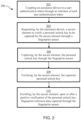
- Fig. 2 shows an illustrative embodiment of a method 200 for enrolling fingerprint reference data in a user authentication token.
- the method 200 comprises, at 202, coupling an assistance device to a user authentication token through an interface of said user authentication token. Furthermore, the method 200 comprises, at 204, requesting, by the assistance device, a secure element to verify a personal unlock key to be captured by the secure element through a fingerprint sensor. Furthermore, the method 200 comprises, at 206, capturing, by the secure element, the personal unlock key through the fingerprint sensor. Furthermore, the method 200 comprises, at 208, verifying, by the secure element, the captured personal unlock key. Finally, the method 200 comprises, at 210, enrolling, by the secure element, upon or after a positive verification of the personal unlock key, fingerprint reference data captured through the fingerprint sensor.
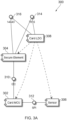
- Fig. 3A shows an example of a token architecture 300.
- Fig. 3A shows components of a typical fingerprint-enabled user authentication token, such as a smart card.
- the token comprises a secure element 304, a card microcontroller (MCU) 302 and a fingerprint sensor 306.
- MCU card microcontroller
- LDO card low dropout regulators
- the secure element 304 handles secure communication with a security network, which may be a payment network.
- the sensor 306 converts biometric features by means of the card MCU 302 into a feature set that is machine readable, more specifically readable by the secure element 304.
- the secure element 304 may e.g.
- token MCU and “card MCU” are used interchangeably, as well as the terms “token interface adapter” and “card adapter”, and “card LDO” and “token LDO”, if not otherwise specified.
- Fig. 3B shows another example of a token architecture 318.
- Fig. 3B shows an example of a typical token that does not have a contactless interface.
- a simplified token architecture is shown, which only has a contact-based interface 314. It is noted that the presently disclosed system and method are not limited to tokens that only have a such a contact-based interface 314; they may equally be applied in tokens having a contactless interface or another interface.
- Fig. 3C shows an example of a smart card 320.
- Fig. 3C shows a typical fingerprint-enabled smart card 320, having an ISO contact module 322 that effectively implements the contact-based interface (ISO 7816).
- the smart card contains a fingerprint verification module 324 operatively coupled to the ISO contact module 322.
- the fingerprint verification module 324 typically contains a secure element, an application processor, and a fingerprint sensor: the fingerprint sensor may provide captured fingerprint data to the application processor, which may forward said fingerprint data the secure element. The secure element may then verify said fingerprint data, for example by comparing them with stored fingerprint reference data of the kind set forth above.
- a loop antenna 326 may be provided for establishing contactless communication.
- Fig. 4 shows an illustrative embodiment of a token architecture 400.
- the token comprises components as shown in Figs. 3A and 3B .
- An interface MCU 402 i.e. a microcontroller comprised in an assistance device of the kind set forth, is connected to the contact-based interface 314 of the token.
- a power source 404 may be connected to both the interface MCU 308 and the card LDO 308, in order to provide operating power to said interface MCU 308 and the various components of the token (secure element 304, card MCU 302, and sensor 306). It is noted that both the power source 404 and the interface MCU 402 are external to the token.
- the secure element 304 should receive a corresponding command, for example formatted as an application protocol data unit (APDU). For security reasons, the secure element 304 should behave as a slave towards an external security network.
- APDU application protocol data unit
- a programmable interface MCU 402 may be executing code that sends the required command APDU through the ISO 7816 interface 314 to the token's secure element 304. Since enrolment requires user entry and user feedback, the interface MCU 402 may also control a simple user interface.
- Fig. 5 shows an illustrative embodiment of a PUK entry and verification flow 500. More specifically, interactions between the assistance device 502 (i.e., adapter), secure element 504, biometric subsystem 506 (e.g., processing unit), and fingerprint sensor 508 are shown. These interactions may implement the PUK entry and verification flow. In short, the PUK entry and verification flow may contain the following elements:
- Fig. 6 shows an illustrative embodiment of a fingerprint reference data enrolment flow 600. More specifically, interactions between the assistance device 602 (i.e., adapter) and the token 604 (i.e., biometric smart card) are shown.
- the smart card comprises the secure element, biometric subsystem and fingerprint sensor, which are not shown separately in this figure. These interactions may implement the fingerprint reference data enrolment flow.
- the token 604 may be activated for enrolment.
- the activation status may be implemented by setting/resetting an activation flag.
- the PUK is provided as a 3-dimensional key, removal of the key from the sensor may be indicative for configuring the token 604 for enrolment.
- a signal provided by the cardholder that may e.g. be a long press by finger on the sensor, may configure the token 604 for enrolment.
- optical feedback indicators e.g. LEDs
- the core of the enrolment functionality may be implemented as an enrolment application being securely executed by the secure element.
- the token interface may only poll the status of the enrolment application and stimulate user actions or provide status feedback to the user. This approach maintains security integrity and leaves full control of enrolment to the secure element. Whatever is executed in terms of enrolment may only run under control of the secure element.
- the user interface shown by way of example in the sequence diagram may only synchronize with the enrolment process executed by the secure element by exchange of status information.
- the token interface may translate the status information into feedback representing user task requests or user feedback.
- Such status information may comprise: Table 1 Task Request Feedback Request sample of new finger Finger attached Captured successfully Move less Capture Error Request Sample of current finger Finger attached Captured successfully Move less Capture Error PUK Verified PUK Error Enrolment Successful Enrolment Error
- the generation of the reference data set may be spread over an initial generation of a subset of the reference dataset and a succeeding period collecting and adding additional reference template members at successful authentications as an extension of the reference dataset until a number of templates has been collected that satisfies the False Acceptance Rate (FAR) and False Reject Rate (FRR) requirements of the biometric system.
- FAR False Acceptance Rate
- FRR False Reject Rate
- Starting with a lower number of reference samples may either result in an increased FRR or an increased FAR, depending of the setting of the biometric system.
- a potential decrease of the FAR may be offset by invoking PIN-entry as secondary cardholder verification method in case of transaction values exceeding a pre-defined level.
- This approach not only enhances the convenience for the token holder significantly as only a limited number of reference template members need to be captured and added to the reference template data set during an initial enrolment process, but it also improves the quality of the reference template data set.
- the time elapsed between successive template member acquisitions enhances the reliability of the reference template data set especially in terms of FRR as this method may also cover natural and random spreads caused by time-based variation of fingerprints.
- dynamic template renewal may be randomly executed when a randomly defined life-time interval associated to a member of a template data set has elapsed with the purpose to consider long-time variations of fingerprints.
- a member of a reference template data set being associated to the finger being applied for an actual authentication may, in case of a successful authentication, be replaced by a new reference template member created from the captured fingerprint.
- the reference template member to be replaced may be chosen randomly. The procedure and the parameters controlling the dynamic template renewal must reside within the secure element.
- Fig. 7 shows an illustrative embodiment of a user authentication system 700.
- the system comprises an adapter 702 (i.e., an assistance device), a secure element 704, a fingerprint sensor 706, a token MCU 708, and a power supply 710.
- the adapter MCU may send APDU commands to the token's secure element 704 that may stimulate the token to facilitate a token owner authentication, and in another processing step, to capture multiple token holder's fingerprint samples, process them into templates and add such templates as members to a reference template data set being securely stored within the secure element 704.
- the adapter 702 may contain an ISO 7816 interface that enables the adapter MCU to communicate command instructions to the secure element 704 embedded in the token, specifically to a computer program that is stored in, and can be executed by, the secure element 704. Said instructions may be decoded and executed by said computer program.
- the ISO 7816 interface of the adapter 702 may be implemented by a hardcoded functional block or by a soft-coded functional block.
- Fig. 8 shows an illustrative embodiment of an ISO/IEC 7816 interface implementation 800. It is noted that ISO/IEC 7816 is referred to as "ISO 7816" in short.
- the adapter MCU 802 and the secure element 804 communicate with each other through an ISO 7816 interface.
- the interface may be configured to comply with various supply voltages, as shown. For instance, by activating either TX1 or TX2 or activating TX1 and TX2 concurrently, appropriate pullup resistors become effective for specific supply voltages.
- Fig. 9 shows an illustrative embodiment of an interface adapter PCB assembly 900.
- the components forming the adapter interface may be implemented as a PCB assembly, as shown.
- Spring contacts may be configured to establish contact with the required token interface pads VCC, VSS, CLK, RESET and IO.
- the feedback element or elements (which may be optical indicators), the adapter MCU and passive components that may be required, may be mounted on a printed circuit board (PCB), which may also provide contact pads for attaching a wire connection to a power source or power supply.
- the power source or power supply may for example be a supply voltage provided by a universal serial bus (USB) port of an external device.
- the external device may for example be a USB charger, a laptop, a car, a plane, a power bank.
- Fig. 10 shows an illustrative embodiment of card packaging sheets 1000.
- the housing for the token interface adapter may be made from packaging material that is normally used to ship the token safely to the token holder.
- a part of the packaging material is configured to form prepunched components, that after breakout may be assembled quickly to form the token interface adapter.
- Fig. 10 shows the assembly of the token interface adapter.
- the token is a smart card.
- FIG. 11 shows an illustrative embodiment of assembly steps 1100.
- a token fixture that may be assembled from breakout parts may be designed such that it takes up the token exactly. Such a fixture may enable a precise positioning of a finger on the fingerprint sensing area.
- Bottom and card layer may be preassembled and serve as packaging for the card (i.e., the token) when sent to the token holder.
- the link layer may have bulges for facilitating the fixing of the token interface adapter. To fix the token interface adapter, it is inserted into the fixture and then slid over the card's contact area. The top layer may cover the bulges of the link layer, thus providing support for fixing the interface adapter.
- Fig. 12 shows another illustrative embodiment of assembly steps 1200.
- the token interface adapter is assembled from breakout parts of the link layer sheet and a pre-assembled PCB with an attached power connection cable. The first two parts are joined by suitable means, the PCB assembly is inserted such that the contact springs reach though the bottom part and the feedback indicators face the top side. The top plate is joined by suitable means as well, which completes the assembly of the interface adapter.
- the token interface adapter assembly has bulges that fix the token interface adapter to the token fixture and that make sure that the token interface adapter is positioned exactly above the card to gain correct access to the card's contact interface.
- the optical feedback indicator faces the cardholder.
- the signals provided to the user may be:
- Fig. 13 shows an illustrative embodiment of a three-dimensional code pattern 1300.
- the fingerprint sensor itself may be utilized for entering a PUK.
- the fingerprint sensor may provide a direct option for entering data into the token.
- a fingerprint sensor is designed to capture 3-dimensional patterns; for this reason, such a sensor may also be utilized to capture 3-dimensional code patterns that are not fingerprints. Therefore, the PUK may be read by the fingerprint sensor if the PUK takes the form of a sensor-readable 3-dimensional structure, which will significantly increase the cardholder's convenience level.
- data are encoded by modulating at predefined data positions the z-axis. Such data positions may be arranged in a matrix type structure as shown in Fig 13 .
- a 6x6 dot code matrix represents a 32-bit code including a rotation indicator. Corner positions may be pre-coded by a pattern that enables rotation identification.
- a code may be structured on a conductive substrate by printing with conductive ink.
- the height of printed dots may match the height of average fingerprint ridges, which is about 25 ⁇ m.
- the diameter of the dots may e.g. be between 100 ⁇ m and 300 ⁇ m, the dot pitch e.g. between 600 ⁇ m and 1000 ⁇ m.
- the resulting 3-dimensional code may be covered by a protection layer such that the total height of dots and protection layer (above the carrier substrate) may not exceed the normal ridge height of about 25 ⁇ m.
- the 3-dimensional code may be formed by creating holes, e.g. by laser-drilling or by mechanical drilling in a conductive substrate made of e.g. aluminum or copper.
- a 3-dimensional code may be attached by suitable means to a positioning plate at the time of enrolment, as shown in the rightmost column of Fig. 13 .
- a positioning plate which may be configured from breakout material as described above, may facilitate a precise positioning of the 3-dimensional code pattern over the token's fingerprint sensor.
- a printer having a punching effect e.g. matrix printer
- a conductive material may e.g. be aluminum or copper or a carbonized substrate.
- the PUK information may be programmed into the substrate material, resulting in a 3-dimensional code pattern.
- An example for an image collected from a punched aluminum foil with a standard capacitive fingerprint sensor at a resolution of 254 dpi is indicated above (2 nd column from the right). This example may prove, that even code pixel array sizes of 8x8 pixels up to 10x10 pixels may be read by 254 dpi sensors. Sensors with higher resolution may enable even larger code matrix dimensions.
- error correction information may be combined into the code pattern to enable correction of errors that may occur between code generation and code reading.
- the thickness of the carrier substrate may be configured such that it prevents damage of the 3-dimensional code during shipment and as such may avoid the application of a code protecting layer.
- Fig. 14 shows another illustrative embodiment of a three-dimensional code pattern 1400.
- the 3-dimensional code may be delivered to the cardholder by post mail as a sticker, that may be peeled off the PUK-letter 1406 and subsequently be attached to the positioning plate.
- the positioning plate may provide an option to apply the 3-dimensional code to the sensor with exact placement directly over the fingerprint sensor. For achieving that, the positioning plate may be configured to fit only in one orientation into the token fixture as described above.
- the 3-dimensional code may be processed into a grayscale image, that may be further processed into a PUK.
- the 3-dimensional key may be attached to a film carrier, that may be fixed to the positioning plate.
- the token holder may press the key with his finger against the sensor to achieve the best possible reading performance.
- This embodiment may be well suited for capacitive fingerprint sensors having a drive electrode (bezel) that normally establishes galvanic contact to the finger.
- the film may exhibit a slight spring effect, that removes the 3-dimensional PUK from the sensor when the finger is released. Said effect may emulate the function of an encoded switch.
- the token adapter may indicate to the secure element that a finger may be attached to the fingerprint sensor.
- a resistor being inserted in either the power line or the ground line may be configured to act as a short circuit protection to avoid a short circuit caused by not placing the token interface adapter correctly over the token.
- the token interface adapter may indicate to the secure element that a finger with ordinal number n may be attached to the fingerprint sensor.
- the token interface adapter may indicate to the secure element that a finger with ordinal number n may be attached to the fingerprint sensor to capture a template having ordinal number m .
- the number of fingers used for capturing reference template data sets may be larger than 2.
- the number of feedback indicators may differ from the number of 2 or the number of 3.
- the token interface adapter may be pre-assembled from components made e.g. of thermoplastic material and from a PCB pre-assembly. This embodiment may minimize the effort for setting up the token interface.
- Fig. 15 shows another illustrative embodiment of a user authentication system 1500.
- the adapter's interface may be configured as a USB to ISO7816 interface, so that the secure element of the smart card may communicate through said interface with a host device executing an enrolment application, wherein said enrolment application may also provide a user interface.
- the adapter 1502 may form in conjunction with the host device a standard card reader that may be utilized for card access beyond enrolment, e.g. for authenticating a payment transaction by fingerprint through the host device, which may be connected to a payment network. Such an embodiment is shown in Fig. 15 .
- Fig. 16 shows a further illustrative embodiment of a user authentication system 1600.
- the adapter 1602 may be configured to communicate with the token by a contactless ISO 14443 interface.
- a transmitter coil may be embedded between the bottom layer and the card layer and the antenna terminals may be connected to a conducting interface, which may enable operational coupling of the antenna terminals to the adapter 1602 when it is positioned in the locked position.
- the adapter MCU may also be configured to encode and decode communication according to ISO 14443.
- capturing of a fingerprint and generation of at least one reference template data set member may be initiated by the token MCU itself without involvement of the secure element.
- a public key may be derived from the PUK and the at least one reference template data set member being generated may be encrypted by the public key and stored persistently inside the token MCU.
- the token MCU may signal to the secure element that at least one new reference template data set member may be available.
- the secure element may collect the at least one encrypted reference template data set member from the token MCU and may decrypt them by a private key being derived from the same PUK.
- at least one reference template data set member may be stored in the insecure memory of the token MCU.
- the at least one reference template data set member may be added to the reference template data set inside the secure element; from that perspective the reference template information stored inside the insecure memory of the token MCU may not be utilized by unauthorized third parties who are not in possession of the private key.
- Such a private key should be securely stored inside the secure element.
- a simplified version of the token interface may be sufficient, which may only provide optical feedback to the token fixture.
- the token MCU may utilize the powerline to control an optical indicator inside the token interface adapter. This method may avoid additional communication lines between the token and the token interface adapter, thus saving cost.
- Fig. 17 shows an illustrative embodiment of a current sensor 1700.
- the token MCU may stimulate two conditions: in the first condition, the token MCU may stimulate a total token supply current that may be deliberately set to a minimum below the minimal operational supply current, in the second condition the token MCU may stimulate a token supply current that may be set above the maximum operational supply current of the token.
- a parallel load may be activated during all token activities with involvement of the token MCU. To stimulate the first condition, said parallel load is detached.
- the token MCU may increase its own supply current. Increasing the supply current may be achieved without a need for external components by e.g.
- a current sensor in the adapter interface may sense both conditions. This may be achieved by a current sensor as shown in Fig. 17 .
- Such a current sensor may work as follows: over a series resistor, which may be a short-circuit protection resistor 1702, a voltage drop may develop if the token interface adapter may be operationally coupled to the token. Such voltage drop may be indicative for the current drawn by the token.
- a voltage comparator may be utilized to compare a fraction of the supply voltage versus a fraction of the difference of the supply voltage and said voltage drop. Said voltage comparator may be configured to activate a LED if e.g. the voltage drop exceeds a level being predefined by the components forming the input voltages for the voltage comparator.
- Fig. 18 shows a further illustrative embodiment of a user authentication system 1800.
- a switch may be connected via a load resistor between a series resistor within the supply line and ground.
- the voltage-drop developing across said series resistor when switching the load resistor to ground may be measured by an Analog-to-Digital converter that may be integrated in the adapter MCU.
- a key-press at the adapter 1802 may be identified by the adapter MCU. This method may be applied to differentiate key presses on different switches switching different loads.
- the adapter MCU may be configured to measure the voltage without key presses upon adapter power-up. Applying relative switching levels to the measured supply voltage may enable the adapter MCU to convert relative switching levels into absolute voltage levels for sensing by its ADC.
- the power supply may be a battery that is operationally coupled to the adapter PCB assembly.
- the power supply is a solar panel that is operationally coupled to the adapter PCB assembly.
- Fig. 19 shows an illustrative embodiment of a gesture-based PUK entry 1900.
- the PUK information may be entered by capturing gestures being indicative of codes of a code alphabet of gestures.
- the size of a fingerprint sensor may allow the practical entry of a limited number of gestures that may e.g. comprise diagonal, vertical and horizontal movement over the sensor with a finger.
- These gestures may be processed into a machine-readable format, such that a sequence of gestures may be converted into a sequence or ordinal number that may be interpreted as a PUK to enable access to the enrolment process.
- the optical feedback indicators may be replaced by acoustical feedback indicators with the purpose of providing a token enrolment user interface to visually impaired people.
- the optical feedback indicators may be replaced by tactile feedback indicators with the purpose of providing a token enrolment user interface to visually impaired people.
- a fingerprint sensor may be beyond the enrolment use case utilized to decode a three-dimensional pattern, which is not a fingerprint, with the purpose of deriving a machine-readable code from it, which may be utilized as a personal key for gaining access to a service or a site.
- the code entropy of a 10x10 pixel pattern may theoretically be 2100 if differentiation of two states per code position is assumed.
- the 3-dimensional key is configured to comply with the requirement of an ultrasonic sensor which may require modifying the dimensions of the encoding pattern.
- the 3-dimensional key may be configured to comply with the requirement of an infrared sensor which may require modifying the material of the substrate carrying the encoding pattern.
- a reading device with an embedded fingerprint sensor may be utilized to sense a 3-dimensional code being embedded in the surface of a device, wherein the z-resolution of the third dimension enables a higher code density than what may currently be achieved by planar codes. Such 3-dimensional codes may be more difficult to read by unauthorized individuals.
- Fig. 20 shows a further illustrative embodiment of a user authentication system 2000.
- the role of the adapter MCU may be carried out by the token MCU.
- the token MCU 2008 may provide an emulated ISO 7816 interface that may be operationally connected to the ISO 7816 interface of the secure element, when the token MCU 2008 may identify from the signal levels on the token's 7816 interface that the token is not connected to an ISO 7816 host system. If operationally connected, the token MCU 2008 may act as the adapter MCU. In this function, it may provide a stimulating APDU sequence to the secure element to trigger PUK acquisition and later enrolment. In this configuration, no adapter MCU is required.
- the current sensing method as described above may be applied to control suitable user feedback devices as disclosed before.
- extra cost for an adapter MCU may be saved and, moreover, the manufacturer of the token may safeguard that the required functionality of the adapter MCU as embedded in the token MCU 2008 may always match his requirements.
- Fig. 21 shows a further illustrative embodiment of a user authentication system 2100.
- the adapter 2102 may be configured to provide power to the token by means of a radio frequency (RF) field generated through a loop antenna that is operationally coupled to the adapter 2102 and, moreover, the role of the adapter MCU may be performed by the token MCU 2108.
- the token MCU 2108 may provide an emulated ISO 7816 interface that is operationally coupled to the ISO 7816 interface of the secure element, when the token MCU 2108 identifies from missing or unspecified signal levels on the token's 7816 interface that the token is not connected to an ISO 7816 host system.
- the token MCU 2108 may act as the adapter MCU. In this function, it may provide a stimulating APDU sequence to the secure element to trigger PUK acquisition and later enrolment. In this configuration, no adapter MCU may be required.
- load modulation of the RF field may be stimulated by the token MCU to signal activity of feedback indicators.
- the load modulation may be detected by the adapter 2102 by means of a demodulator and translated into control for feedback elements, thus virtually connecting the feedback elements contained in the adapter 2102 in a contactless manner to the token MCU 2108.
- extra cost for an adapter MCU may be saved and, moreover, the functionality of the adapter MCU as embedded in the token MCU 2108 may always match the requirements of the token type and version.
- Fig. 22 shows a further illustrative embodiment of a user authentication system 2200.
- the token or card itself may be equipped with user feedback indicators, and the token MCU 2208 may also fulfill the role of the adapter MCU as disclosed above.
- only a power supply may be connected to the token's ISO 7816 interface. This approach may enable the implementation of a least cost self-enrolment interface.
- the feedback indicators may be located near the sensor, as the sensor may always be exposed to the user.
- the adapter PCB may be configured such that it may show a flat topology (achieved e.g. by dam and fill over-molding), which may make it simpler to embed such a PCB assembly in the adapter housing while ensuring a fixed vertical position of the contact springs.
- the systems and methods described herein may at least partially be embodied by a computer program or a plurality of computer programs, which may exist in a variety of forms both active and inactive in a single computer system or across multiple computer systems.
- they may exist as software program(s) comprised of program instructions in source code, object code, executable code or other formats for performing some of the steps.
- Any of the above may be embodied on a computer-readable medium, which may include storage devices and signals, in compressed or uncompressed form.
- the term "computer” refers to any electronic device comprising a processor, such as a general-purpose central processing unit (CPU), a specific-purpose processor or a microcontroller.
- a computer is capable of receiving data (an input), of performing a sequence of predetermined operations thereupon, and of producing thereby a result in the form of information or signals (an output).
- the term "computer” will mean either a processor in particular or more generally a processor in association with an assemblage of interrelated elements contained within a single case or housing.
- processor or “processing unit” refers to a data processing circuit that may be a microprocessor, a co-processor, a microcontroller, a microcomputer, a central processing unit, a field programmable gate array (FPGA), a programmable logic circuit, and/or any circuit that manipulates signals (analog or digital) based on operational instructions that are stored in a memory.
- memory refers to a storage circuit or multiple storage circuits such as read-only memory, random access memory, volatile memory, non-volatile memory, static memory, dynamic memory, Flash memory, cache memory, and/or any circuit that stores digital information.
- a "computer-readable medium” or “storage medium” may be any means that can contain, store, communicate, propagate, or transport a computer program for use by or in connection with the instruction execution system, apparatus, or device.
- the computer-readable medium may be, for example but not limited to, an electronic, magnetic, optical, electromagnetic, infrared, or semiconductor system, apparatus, device, or propagation medium.
- the computer-readable medium may include the following: an electrical connection having one or more wires, a portable computer diskette, a random access memory (RAM), a read-only memory (ROM), an erasable programmable read-only memory (EPROM or Flash memory), an optical fiber, a portable compact disc read-only memory (CDROM), a digital versatile disc (DVD), a Blu-ray disc (BD), and a memory card.
- RAM random access memory
- ROM read-only memory
- EPROM or Flash memory erasable programmable read-only memory
- CDROM compact disc read-only memory
- DVD digital versatile disc
- BD Blu-ray disc
Description
- The present disclosure relates to a user authentication system. Furthermore, the present disclosure relates to a method for enrolling fingerprint reference data. Fingerprint sensing devices, such as capacitive fingerprint sensors, may be integrated into user authentication tokens, for example into smart cards. In order to personalize such a user authentication token, fingerprint reference data should be enrolled into the user authentication token. More specifically, a fingerprint template should be stored in a secure element of the token, so that - in operation - a captured fingerprint can be compared with said template in order to authenticate a user. A secure element may for example be an embedded chip, more specifically a tamper-resistant integrated circuit with installed or pre-installed smart-card-grade applications, for instance payment applications, which have a prescribed functionality and a prescribed level of security. Furthermore, a secure element may implement security functions, such as cryptographic functions and authentication functions. The enrolment of fingerprint reference data is often performed under supervision in a secure environment, for example at the premises of a bank. This process is often not user-friendly and time-consuming. Thus, it is desirable to facilitate enrolling fingerprint reference data into user authentication tokens of the kind set forth.
-
US 2017/0286789 A1 describes a biometric authorized smartcard that comprises: a biometric sensor; a control system for controlling operation of the smartcard; and a graphical user interface for displaying alphanumeric information to a user of the smartcard. The smartcard has one or more protected features that are accessible to a user identified via the biometric sensor and the graphical user interface displays information in response to interaction of the user with the biometric sensor. The information can be used to guide enrolment of a user via the biometric sensor and/or to aid the interaction of the user with the biometric sensor during biometric authorization after enrolment. - In accordance with a first aspect of the present disclosure, a user authentication system is provided, as defined in
claim 1. - In accordance with a second aspect of the present disclosure, a method for enrolling fingerprint reference data in a user authentication token is conceived, as defined in claim 11.
- In accordance with a third aspect of the present disclosure, a computer program is provided, comprising executable instructions which, when executed by an assistance device or a secure element, cause said assistance device and secure element, respectively, to carry out steps of a method of the kind set forth.
- Advantageous embodiments are defined in the dependent claims.
- Embodiments will be described in more detail with reference to the appended drawings, in which:
-
Fig. 1 shows an illustrative embodiment of a user authentication system; -
Fig. 2 shows an illustrative embodiment of a method for enrolling fingerprint reference data in a user authentication token; -
Fig. 3A shows an example of a token architecture; -
Fig. 3B shows another example of a token architecture; -
Fig. 3C shows an example of a smart card; -
Fig. 4 shows an illustrative embodiment of a token architecture; -
Fig. 5 shows an illustrative embodiment of a PUK entry and verification flow; -
Fig. 6 shows an illustrative embodiment of a fingerprint reference data enrolment flow; -
Fig. 7 shows an illustrative embodiment of a user authentication system; -
Fig. 8 shows an illustrative embodiment of an ISO/IEC 7816 interface implementation; -
Fig. 9 shows an illustrative embodiment of an interface adapter PCB assembly; -
Fig. 10 shows an illustrative embodiment of card packaging sheets; -
Fig. 11 shows an illustrative embodiment of assembly steps; -
Fig. 12 shows another illustrative embodiment of assembly steps; -
Fig. 13 shows an illustrative embodiment of a three-dimensional code pattern; -
Fig. 14 shows another illustrative embodiment of a three-dimensional code pattern; -
Fig. 15 shows another illustrative embodiment of a user authentication system; -
Fig. 16 shows a further illustrative embodiment of a user authentication system; -
Fig. 17 shows an illustrative embodiment of a current sensor; -
Fig. 18 shows a further illustrative embodiment of a user authentication system; -
Fig. 19 shows an illustrative embodiment of a gesture-based PUK entry; -
Fig. 20 shows a further illustrative embodiment of a user authentication system; -
Fig. 21 shows a further illustrative embodiment of a user authentication system; -
Fig. 22 shows a further illustrative embodiment of a user authentication system. - Fingerprint sensing devices, such as capacitive fingerprint sensors, may be integrated into user authentication tokens, for example into smart cards. In order to personalize such a user authentication token, fingerprint reference data should be enrolled into the user authentication token. More specifically, a fingerprint template should be stored in a secure element of the token, so that - in operation - a captured fingerprint can be compared with said template in order to authenticate a user. The enrolment of fingerprint reference data is often performed under supervision in a secure environment, for example at the premises of a bank. This process is often not user-friendly and time-consuming. Thus, it is desirable to facilitate enrolling fingerprint reference data into user authentication tokens of the kind set forth.
- More specifically, tokens such as smart wearables or smart cards equipped with a fingerprint-based user authentication function require the user to enrol his biometric credentials (i.e., fingerprint template) as reference data for later verification on the token. For adequate storage, the sensitive biometric credentials must be securely stored within such fingerprint-authenticated tokens. Currently, this enrolment process for payment tokens requires either an external computer, smartphone or internet connection or an enrolment at a bank branch. From a convenience perspective, it would be better to perform fingerprint enrolment on the token in a private environment, i.e. at the premises of the token holder, without compromising the security level of the token. For this purpose, a fingerprint template should be stored safely inside a secure element being embedded in such token. However, before enabling such an enrolment of a fingerprint template, the identity of the user should somehow be verified, so that the correct fingerprint template is enrolled - and not the template of a malicious person, for example when the token has been stolen. As mentioned, this identity verification is typically done at the premises of a token issuer (e.g., a bank), which is not user-friendly and time-consuming.
- Therefore, in accordance with the present disclosure, a user authentication system is provided, comprising a user authentication token, wherein the user authentication token comprises a fingerprint sensor and a secure element. Furthermore, the system comprises an assistance device configured to be coupled to the user authentication token through an interface of said user authentication token. In addition, the assistance device is configured to request the secure element to verify a personal unlock key (PUK) to be captured by the secure element through the fingerprint sensor, and the secure element is configured to capture the personal unlock key through the fingerprint sensor, to verify the captured personal unlock key and to enrol, upon or after a positive verification of the personal unlock key, fingerprint reference data captured through the fingerprint sensor. In this way, by verifying a personal unlock key (PUK) before the fingerprint reference data are enrolled, the identity of the user can be verified securely in a private environment. Furthermore, since only a single sensor is used for capturing the PUK and the fingerprint reference data, the identity of the user can be verified in a resource-efficient way. It is noted that the assistance device is also referred to herein as an enrolment adapter, as a token interface or token interface adapter, or in short as an "adapter".
- The PUK is a three-dimensional code pattern that is not a fingerprint. More specifically, the three-dimensional code pattern is formed as a sensor-readable 3-dimensional structure having data encoded thereon by modulation of the z-axis of the structure at predefined data positions. Such a pattern can easily be read by a fingerprint sensor. Thus, this embodiment facilitates using only a single sensor (i.e., the fingerprint sensor) for capturing the PUK and the fingerprint reference data. Furthermore, in an embodiment, the three-dimensional code pattern is a printable code pattern. In this way, the PUK can easily be delivered to a user, for example in shipping letter which is sent to a user separately from the user authentication token. Alternatively, the three-dimensional code pattern may be a code pattern created by punching holes in a substrate. Such a punching method or impacting method is a subtractive coding method, which has the advantage that the three-dimensional code pattern still exhibits a flat surface towards the surface of the fingerprint sensor. This, in turn, enables an adequate coupling to the fingerprint sensor.
- Furthermore, in an embodiment, the three-dimensional code pattern is configured to be attached to or embedded in a document. For example, the code pattern may be printed and attached to the above-mentioned shipping letter. In that case, the user may simply detach the code pattern from the letter, and place the code pattern on the fingerprint sensor when prompted to do so. Thus, this embodiment increases the user convenience. Alternatively, or in addition, at least a part of the PUK may comprise one or more gestures representing code elements of a known code alphabet. Gesture-based code entry has been described in, inter alia,
EP 2 575 084 A1 - In a practical and effective implementation, the interface is a contact-based interface according to the standard ISO/
IEC 7816. In this way, since a standardized and commonly available interface is used, no additional interface needs to be provided for connecting the assistance device to the secure element. Alternatively, the interface may be a contactless interface according to the standard ISO/IEC 14443. Furthermore, in an embodiment, the assistance device is further configured to provide power to the user authentication token. A user authentication token of the kind set forth often does not contain a power source. For example, a smart card does often not have a battery, but it is powered by an external device - e.g. a reader embedded in a payment terminal - either through a contact-based interface (ISO/IEC 7816) or a contactless interface (ISO/IEC 14443). Such an external device is often not available when the user receives the smart card and wishes to commence the enrolment process. Therefore, the assistance device may be configured to provide power to the user authentication, in a comparable way as said external device, for example through the contact-based interface (ISO/IEC 7816). For this purpose, the assistance device may contain its own power source (e.g., a battery) or be connected to an external power source. - In an embodiment, the assistance device is further configured to facilitate fixing a position of the user authentication token. In this way, in case the PUK is a three-dimensional code pattern, for example, the user may easily place the PUK on the fingerprint sensor. It can be envisaged, for example, that a smart card is delivered in a package made of cardboard, and that the assistance device is integrally formed with said cardboard package. In that case, the cardboard package may fix the position of the smart card, and a removable part of the package - having a cut-out, for instance - is placed above the smart card so that the cut-out indicates to the user where the three-dimensional code pattern should be placed. Thus, this embodiment increases the user convenience. Furthermore, in an embodiment, the assistance device is included in a delivery package that comprises the user authentication token. In this way, the assistance device can easily be delivered to the user. For instance, in the above-described example, the assistance device can be integrally formed with a cardboard package in which a smart card is shipped to a user. The PUK can then be sent in a separate shipping letter to the user. This is a cheap and convenient, yet secure, way to deliver the user authentication token, the assistance device and the PUK to the user. Furthermore, in a practical and effective implementation, the assistance device is at least partially made of the same material - e.g. cardboard - as the delivery package. In addition, the assistance device contains electronic components for performing its function or functions. Finally, in an embodiment, the assistance device comprises an optical feedback unit configured to provide optical feedback to a user. Such an optical feedback unit may guide the user through the PUK entry and fingerprint reference data enrolment process, as will be explained in more detail below. In a practical and effective implementation, the optical feedback unit comprises one or more light-emitting diodes (LEDs). LEDs do not consume much power and can easily be controlled.
-
Fig. 1 shows an illustrative embodiment of auser authentication system 100. Thesystem 100 comprises auser authentication token 102 and anassistance device 108 of the kind set forth. Theuser authentication token 102 comprises asecure element 104 and afingerprint sensor 106. Theassistance device 108 is configured to request thesecure element 104, e.g. by means of a command (CMD), to verify a personal unlock key (PUK) to be captured by thesecure element 104 through thefingerprint sensor 106. Thesecure element 104 may be configured to initiate - optionally via a processing unit or microcontroller (not shown) - a measurement process of thefingerprint sensor 106. The user may then be prompted to place the PUK on thesensor 106, for example, and thefingerprint sensor 106 reads out the PUK. Thus, thesecure element 104 effectively captures the PUK through thefingerprint sensor 106. Furthermore, thesecure element 104 is configured to verify the captured PUK and to enrol, upon or after a positive verification PUK, fingerprint reference data captured through thefingerprint sensor 106. For this purpose, thesecure element 104 may again be configured to initiate - optionally via said processing unit or microcontroller - a measurement process of thefingerprint sensor 106. The user may then be prompted to place his finger on thesensor 106, for example, and thefingerprint sensor 106 reads out the fingerprint reference data. Thesecure element 104 may enrol the fingerprint reference data by storing said data securely in a memory unit (not shown) of thesecure element 104. -
Fig. 2 shows an illustrative embodiment of amethod 200 for enrolling fingerprint reference data in a user authentication token. Themethod 200 comprises, at 202, coupling an assistance device to a user authentication token through an interface of said user authentication token. Furthermore, themethod 200 comprises, at 204, requesting, by the assistance device, a secure element to verify a personal unlock key to be captured by the secure element through a fingerprint sensor. Furthermore, themethod 200 comprises, at 206, capturing, by the secure element, the personal unlock key through the fingerprint sensor. Furthermore, themethod 200 comprises, at 208, verifying, by the secure element, the captured personal unlock key. Finally, themethod 200 comprises, at 210, enrolling, by the secure element, upon or after a positive verification of the personal unlock key, fingerprint reference data captured through the fingerprint sensor. -
Fig. 3A shows an example of atoken architecture 300. In particular,Fig. 3A shows components of a typical fingerprint-enabled user authentication token, such as a smart card. The token comprises asecure element 304, a card microcontroller (MCU) 302 and afingerprint sensor 306. For power conditioning, a card low dropout regulators (LDO) 308 is provided. Thesecure element 304 handles secure communication with a security network, which may be a payment network. Thesensor 306 converts biometric features by means of thecard MCU 302 into a feature set that is machine readable, more specifically readable by thesecure element 304. In case of a smart card, thesecure element 304 may e.g. communicate through standardized interfaces, such as a contact-based interface (ISO 7816) 314 or a contactless interface (ISO 14443) 316. In case of a smart wearable device, the communication may be established e.g. through a Bluetooth or Wi-Fi channel. In case of a smart card, power may be derived through said communication interfaces. It is noted that, in this description, the terms "token MCU" and "card MCU" are used interchangeably, as well as the terms "token interface adapter" and "card adapter", and "card LDO" and "token LDO", if not otherwise specified. -
Fig. 3B shows another example of atoken architecture 318. In particular,Fig. 3B shows an example of a typical token that does not have a contactless interface. In other words, a simplified token architecture is shown, which only has a contact-basedinterface 314. It is noted that the presently disclosed system and method are not limited to tokens that only have a such a contact-basedinterface 314; they may equally be applied in tokens having a contactless interface or another interface. -
Fig. 3C shows an example of asmart card 320. In particular,Fig. 3C shows a typical fingerprint-enabledsmart card 320, having anISO contact module 322 that effectively implements the contact-based interface (ISO 7816). Furthermore, the smart card contains afingerprint verification module 324 operatively coupled to theISO contact module 322. Thefingerprint verification module 324 typically contains a secure element, an application processor, and a fingerprint sensor: the fingerprint sensor may provide captured fingerprint data to the application processor, which may forward said fingerprint data the secure element. The secure element may then verify said fingerprint data, for example by comparing them with stored fingerprint reference data of the kind set forth above. Furthermore, aloop antenna 326 may be provided for establishing contactless communication. -
Fig. 4 shows an illustrative embodiment of atoken architecture 400. The token comprises components as shown inFigs. 3A and3B . Aninterface MCU 402, i.e. a microcontroller comprised in an assistance device of the kind set forth, is connected to the contact-basedinterface 314 of the token. Apower source 404 may be connected to both theinterface MCU 308 and thecard LDO 308, in order to provide operating power to saidinterface MCU 308 and the various components of the token (secure element 304,card MCU 302, and sensor 306). It is noted that both thepower source 404 and theinterface MCU 402 are external to the token. - To stimulate enrolment under involvement of the
secure element 304, thesecure element 304 should receive a corresponding command, for example formatted as an application protocol data unit (APDU). For security reasons, thesecure element 304 should behave as a slave towards an external security network. For providing such a stimulating command APDU, aprogrammable interface MCU 402 may be executing code that sends the required command APDU through theISO 7816interface 314 to the token'ssecure element 304. Since enrolment requires user entry and user feedback, theinterface MCU 402 may also control a simple user interface. -
Fig. 5 shows an illustrative embodiment of a PUK entry andverification flow 500. More specifically, interactions between the assistance device 502 (i.e., adapter),secure element 504, biometric subsystem 506 (e.g., processing unit), andfingerprint sensor 508 are shown. These interactions may implement the PUK entry and verification flow. In short, the PUK entry and verification flow may contain the following elements: - a user connects a token to the
enrolment adapter 502; - the
enrolment adapter 502 establishes a secure communication session with thesecure element 504; - the
enrolment adapter 502 requests the user, e.g. using an optical feedback indicator or other user interface, to authenticate towards the token by providing a PUK; - the
enrolment adapter 502 sends a request to the token, in particular to thesecure element 504, to capture and verify the token holder's PUK; - the token holder enters his PUK through the fingerprint sensor's surface;
- the PUK is compared by the
secure element 504 against a secret stored within thesecure element 504 with the purpose to verify the token holder's identity; - upon a negative verification the user may be informed that the PUK-based authentication failed, and the token may be set into an idle mode;
- upon a positive verification the token is enabled for a fingerprint template enrolment process during the established communication session.
-
Fig. 6 shows an illustrative embodiment of a fingerprint referencedata enrolment flow 600. More specifically, interactions between the assistance device 602 (i.e., adapter) and the token 604 (i.e., biometric smart card) are shown. The smart card comprises the secure element, biometric subsystem and fingerprint sensor, which are not shown separately in this figure. These interactions may implement the fingerprint reference data enrolment flow. - If the PUK authentication was successful, the token 604 may be activated for enrolment. The activation status may be implemented by setting/resetting an activation flag. If the PUK is provided as a 3-dimensional key, removal of the key from the sensor may be indicative for configuring the token 604 for enrolment. In case of alternative ways to provide the PUK, a signal provided by the cardholder, that may e.g. be a long press by finger on the sensor, may configure the token 604 for enrolment. When configured for enrolment, optical feedback indicators (e.g. LEDs) may indicate task requests and may also provide feedback on task execution. The core of the enrolment functionality may be implemented as an enrolment application being securely executed by the secure element. Next to starting the enrolment application, the token interface may only poll the status of the enrolment application and stimulate user actions or provide status feedback to the user. This approach maintains security integrity and leaves full control of enrolment to the secure element. Whatever is executed in terms of enrolment may only run under control of the secure element. The user interface shown by way of example in the sequence diagram may only synchronize with the enrolment process executed by the secure element by exchange of status information. The token interface may translate the status information into feedback representing user task requests or user feedback. Such status information may comprise:
Table 1 Task Request Feedback Request sample of new finger Finger attached Captured successfully Move less Capture Error Request Sample of current finger Finger attached Captured successfully Move less Capture Error PUK Verified PUK Error Enrolment Successful Enrolment Error - To reduce the time required to enrol a biometric token, the generation of the reference data set may be spread over an initial generation of a subset of the reference dataset and a succeeding period collecting and adding additional reference template members at successful authentications as an extension of the reference dataset until a number of templates has been collected that satisfies the False Acceptance Rate (FAR) and False Reject Rate (FRR) requirements of the biometric system. Starting with a lower number of reference samples may either result in an increased FRR or an increased FAR, depending of the setting of the biometric system. If not all required reference template members have been captured, a potential decrease of the FAR may be offset by invoking PIN-entry as secondary cardholder verification method in case of transaction values exceeding a pre-defined level. For normal users, majority of transactions may be below such critical transaction value so that secondary cardholder verification method needs to be applied and the template extension period may not be visible to the end user. Finally, it may be the responsibility of the issuing bank to find a good compromise between enrolment convenience and authentication security.
- This approach not only enhances the convenience for the token holder significantly as only a limited number of reference template members need to be captured and added to the reference template data set during an initial enrolment process, but it also improves the quality of the reference template data set. The time elapsed between successive template member acquisitions enhances the reliability of the reference template data set especially in terms of FRR as this method may also cover natural and random spreads caused by time-based variation of fingerprints.
- In some embodiments, dynamic template renewal may be randomly executed when a randomly defined life-time interval associated to a member of a template data set has elapsed with the purpose to consider long-time variations of fingerprints. To avoid security risks, a member of a reference template data set being associated to the finger being applied for an actual authentication may, in case of a successful authentication, be replaced by a new reference template member created from the captured fingerprint. The reference template member to be replaced may be chosen randomly. The procedure and the parameters controlling the dynamic template renewal must reside within the secure element.
-
Fig. 7 shows an illustrative embodiment of auser authentication system 700. The system comprises an adapter 702 (i.e., an assistance device), asecure element 704, afingerprint sensor 706, atoken MCU 708, and apower supply 710. To enable reference template storage within thesecure element 704, the adapter MCU may send APDU commands to the token'ssecure element 704 that may stimulate the token to facilitate a token owner authentication, and in another processing step, to capture multiple token holder's fingerprint samples, process them into templates and add such templates as members to a reference template data set being securely stored within thesecure element 704. For communication, theadapter 702 may contain anISO 7816 interface that enables the adapter MCU to communicate command instructions to thesecure element 704 embedded in the token, specifically to a computer program that is stored in, and can be executed by, thesecure element 704. Said instructions may be decoded and executed by said computer program. TheISO 7816 interface of theadapter 702 may be implemented by a hardcoded functional block or by a soft-coded functional block. -
Fig. 8 shows an illustrative embodiment of an ISO/IEC 7816interface implementation 800. It is noted that ISO/IEC 7816 is referred to as "ISO 7816" in short. In this example, theadapter MCU 802 and thesecure element 804 communicate with each other through anISO 7816 interface. The interface may be configured to comply with various supply voltages, as shown. For instance, by activating either TX1 or TX2 or activating TX1 and TX2 concurrently, appropriate pullup resistors become effective for specific supply voltages. -
Fig. 9 shows an illustrative embodiment of an interfaceadapter PCB assembly 900. The components forming the adapter interface may be implemented as a PCB assembly, as shown. Spring contacts may be configured to establish contact with the required token interface pads VCC, VSS, CLK, RESET and IO. Furthermore, the feedback element or elements (which may be optical indicators), the adapter MCU and passive components that may be required, may be mounted on a printed circuit board (PCB), which may also provide contact pads for attaching a wire connection to a power source or power supply. The power source or power supply may for example be a supply voltage provided by a universal serial bus (USB) port of an external device. The external device may for example be a USB charger, a laptop, a car, a plane, a power bank. -
Fig. 10 shows an illustrative embodiment ofcard packaging sheets 1000. For weight, dimension and cost reasons, the housing for the token interface adapter may be made from packaging material that is normally used to ship the token safely to the token holder. For that reason, a part of the packaging material is configured to form prepunched components, that after breakout may be assembled quickly to form the token interface adapter.Fig. 10 shows the assembly of the token interface adapter. In this example, the token is a smart card. -
Fig. 11 shows an illustrative embodiment of assembly steps 1100. A token fixture that may be assembled from breakout parts may be designed such that it takes up the token exactly. Such a fixture may enable a precise positioning of a finger on the fingerprint sensing area. Bottom and card layer may be preassembled and serve as packaging for the card (i.e., the token) when sent to the token holder. The link layer may have bulges for facilitating the fixing of the token interface adapter. To fix the token interface adapter, it is inserted into the fixture and then slid over the card's contact area. The top layer may cover the bulges of the link layer, thus providing support for fixing the interface adapter. -
Fig. 12 shows another illustrative embodiment of assembly steps 1200. As shown, the token interface adapter is assembled from breakout parts of the link layer sheet and a pre-assembled PCB with an attached power connection cable. The first two parts are joined by suitable means, the PCB assembly is inserted such that the contact springs reach though the bottom part and the feedback indicators face the top side. The top plate is joined by suitable means as well, which completes the assembly of the interface adapter. The token interface adapter assembly has bulges that fix the token interface adapter to the token fixture and that make sure that the token interface adapter is positioned exactly above the card to gain correct access to the card's contact interface. The optical feedback indicator faces the cardholder. - The following options can be envisaged for implementing a user interface in case of offline enrolment:
- The fingerprint sensor may be utilized for data entry
- LEDs may be utilized to provide optical feedback In case of three LEDs the signals provided to the user may be:
- Yellow + blink: user requested to attach same finger
- Yellow constant: template member generation in progress
- Green + blink: user requested to attach new finger
- Green Pulse: PUK read successfully, template member creation successful
- Red Pulse: Error in PUK reading, Error in template member creation
- Green Short Pulse and Yellow Short Pulse: Move finger less
- Green constant: Enrolment successful
- Red constant: Error in enrolment
- In case of two LEDs the signals provided to the user may be:
- Green + blink: user requested to attach same finger
- Green + blink AND Red + blink: user requested to attach new finger
- Green Pulse: PUK read successfully, template member creation successful
- Red Pulse: Error in PUK reading, Error in template member creation
- Green Short Pulse and Red Short Pulse alternating: Move finger less
- Green constant: Enrolment successful
- Red constant: Error in enrolment
-
Fig. 13 shows an illustrative embodiment of a three-dimensional code pattern 1300. In accordance with the present disclosure, the fingerprint sensor itself may be utilized for entering a PUK. The fingerprint sensor may provide a direct option for entering data into the token. A fingerprint sensor is designed to capture 3-dimensional patterns; for this reason, such a sensor may also be utilized to capture 3-dimensional code patterns that are not fingerprints. Therefore, the PUK may be read by the fingerprint sensor if the PUK takes the form of a sensor-readable 3-dimensional structure, which will significantly increase the cardholder's convenience level. To comply with the sensor, data are encoded by modulating at predefined data positions the z-axis. Such data positions may be arranged in a matrix type structure as shown inFig 13 . In the example shown, a 6x6 dot code matrix represents a 32-bit code including a rotation indicator. Corner positions may be pre-coded by a pattern that enables rotation identification. Such a code may be structured on a conductive substrate by printing with conductive ink. The height of printed dots may match the height of average fingerprint ridges, which is about 25 µm. The diameter of the dots may e.g. be between 100 µm and 300 µm, the dot pitch e.g. between 600 µm and 1000 µm. The resulting 3-dimensional code may be covered by a protection layer such that the total height of dots and protection layer (above the carrier substrate) may not exceed the normal ridge height of about 25 µm. - In other embodiments, the 3-dimensional code may be formed by creating holes, e.g. by laser-drilling or by mechanical drilling in a conductive substrate made of e.g. aluminum or copper. Such a 3-dimensional code may be attached by suitable means to a positioning plate at the time of enrolment, as shown in the rightmost column of
Fig. 13 . Such a positioning plate, which may be configured from breakout material as described above, may facilitate a precise positioning of the 3-dimensional code pattern over the token's fingerprint sensor. In other embodiments, a printer having a punching effect (e.g. matrix printer) may be applied to a conductive material that may e.g. be aluminum or copper or a carbonized substrate. By punching, the PUK information may be programmed into the substrate material, resulting in a 3-dimensional code pattern. An example for an image collected from a punched aluminum foil with a standard capacitive fingerprint sensor at a resolution of 254 dpi is indicated above (2nd column from the right). This example may prove, that even code pixel array sizes of 8x8 pixels up to 10x10 pixels may be read by 254 dpi sensors. Sensors with higher resolution may enable even larger code matrix dimensions. In some embodiments, error correction information may be combined into the code pattern to enable correction of errors that may occur between code generation and code reading. Furthermore, in some embodiments, in case a code is implemented by creating holes in a carrier substrate, the thickness of the carrier substrate may be configured such that it prevents damage of the 3-dimensional code during shipment and as such may avoid the application of a code protecting layer. -
Fig. 14 shows another illustrative embodiment of a three-dimensional code pattern 1400. The 3-dimensional code may be delivered to the cardholder by post mail as a sticker, that may be peeled off the PUK-letter 1406 and subsequently be attached to the positioning plate. The positioning plate may provide an option to apply the 3-dimensional code to the sensor with exact placement directly over the fingerprint sensor. For achieving that, the positioning plate may be configured to fit only in one orientation into the token fixture as described above. In a successive processing step, the 3-dimensional code may be processed into a grayscale image, that may be further processed into a PUK. In one embodiment, shown in the middle column ofFig. 14 , the 3-dimensional key may be attached to a film carrier, that may be fixed to the positioning plate. The token holder may press the key with his finger against the sensor to achieve the best possible reading performance. This embodiment may be well suited for capacitive fingerprint sensors having a drive electrode (bezel) that normally establishes galvanic contact to the finger. Furthermore, the film may exhibit a slight spring effect, that removes the 3-dimensional PUK from the sensor when the finger is released. Said effect may emulate the function of an encoded switch. - In some embodiments, the token adapter may indicate to the secure element that a finger may be attached to the fingerprint sensor. In other embodiments, a resistor being inserted in either the power line or the ground line may be configured to act as a short circuit protection to avoid a short circuit caused by not placing the token interface adapter correctly over the token. In some embodiments, the token interface adapter may indicate to the secure element that a finger with ordinal number n may be attached to the fingerprint sensor. In some embodiments, the token interface adapter may indicate to the secure element that a finger with ordinal number n may be attached to the fingerprint sensor to capture a template having ordinal number m. In some embodiments, the number of fingers used for capturing reference template data sets may be larger than 2. In some embodiments, the number of feedback indicators may differ from the number of 2 or the number of 3. In some embodiments, the token interface adapter may be pre-assembled from components made e.g. of thermoplastic material and from a PCB pre-assembly. This embodiment may minimize the effort for setting up the token interface.
-
Fig. 15 shows another illustrative embodiment of auser authentication system 1500. In some embodiments, the adapter's interface may be configured as a USB to ISO7816 interface, so that the secure element of the smart card may communicate through said interface with a host device executing an enrolment application, wherein said enrolment application may also provide a user interface. Thus, theadapter 1502 may form in conjunction with the host device a standard card reader that may be utilized for card access beyond enrolment, e.g. for authenticating a payment transaction by fingerprint through the host device, which may be connected to a payment network. Such an embodiment is shown inFig. 15 . -
Fig. 16 shows a further illustrative embodiment of auser authentication system 1600. In other embodiments, theadapter 1602 may be configured to communicate with the token by acontactless ISO 14443 interface. To support contactless communication, a transmitter coil may be embedded between the bottom layer and the card layer and the antenna terminals may be connected to a conducting interface, which may enable operational coupling of the antenna terminals to theadapter 1602 when it is positioned in the locked position. In this embodiment, the adapter MCU may also be configured to encode and decode communication according toISO 14443. - In other embodiments, capturing of a fingerprint and generation of at least one reference template data set member may be initiated by the token MCU itself without involvement of the secure element. In this case, a public key may be derived from the PUK and the at least one reference template data set member being generated may be encrypted by the public key and stored persistently inside the token MCU. Upon next access to a payment network, the token MCU may signal to the secure element that at least one new reference template data set member may be available. The secure element may collect the at least one encrypted reference template data set member from the token MCU and may decrypt them by a private key being derived from the same PUK. Using this approach, at least one reference template data set member may be stored in the insecure memory of the token MCU. Only if public and private key match the at least one reference template data set member may be added to the reference template data set inside the secure element; from that perspective the reference template information stored inside the insecure memory of the token MCU may not be utilized by unauthorized third parties who are not in possession of the private key. Such a private key should be securely stored inside the secure element. For these embodiments, a simplified version of the token interface may be sufficient, which may only provide optical feedback to the token fixture. For signaling status feedback to the cardholder, the token MCU may utilize the powerline to control an optical indicator inside the token interface adapter. This method may avoid additional communication lines between the token and the token interface adapter, thus saving cost.
-
Fig. 17 shows an illustrative embodiment of acurrent sensor 1700. To control the optical indicator, the token MCU may stimulate two conditions: in the first condition, the token MCU may stimulate a total token supply current that may be deliberately set to a minimum below the minimal operational supply current, in the second condition the token MCU may stimulate a token supply current that may be set above the maximum operational supply current of the token. For achieving the first condition, a parallel load may be activated during all token activities with involvement of the token MCU. To stimulate the first condition, said parallel load is detached. To stimulate the second condition, the token MCU may increase its own supply current. Increasing the supply current may be achieved without a need for external components by e.g. increasing the clock frequency or activating otherwise unused peripheral components that are known to require significant extra current as e.g. ADCs or a PLL. A current sensor in the adapter interface may sense both conditions. This may be achieved by a current sensor as shown inFig. 17 . Such a current sensor may work as follows: over a series resistor, which may be a short-circuit protection resistor 1702, a voltage drop may develop if the token interface adapter may be operationally coupled to the token. Such voltage drop may be indicative for the current drawn by the token. A voltage comparator may be utilized to compare a fraction of the supply voltage versus a fraction of the difference of the supply voltage and said voltage drop. Said voltage comparator may be configured to activate a LED if e.g. the voltage drop exceeds a level being predefined by the components forming the input voltages for the voltage comparator. -
Fig. 18 shows a further illustrative embodiment of auser authentication system 1800. In other embodiments, a switch may be connected via a load resistor between a series resistor within the supply line and ground. The voltage-drop developing across said series resistor when switching the load resistor to ground may be measured by an Analog-to-Digital converter that may be integrated in the adapter MCU. Thus, a key-press at theadapter 1802 may be identified by the adapter MCU. This method may be applied to differentiate key presses on different switches switching different loads. The adapter MCU may be configured to measure the voltage without key presses upon adapter power-up. Applying relative switching levels to the measured supply voltage may enable the adapter MCU to convert relative switching levels into absolute voltage levels for sensing by its ADC. In other embodiments, the power supply may be a battery that is operationally coupled to the adapter PCB assembly. In other embodiments, the power supply is a solar panel that is operationally coupled to the adapter PCB assembly. -
Fig. 19 shows an illustrative embodiment of a gesture-basedPUK entry 1900. In some embodiments, the PUK information may be entered by capturing gestures being indicative of codes of a code alphabet of gestures. The size of a fingerprint sensor may allow the practical entry of a limited number of gestures that may e.g. comprise diagonal, vertical and horizontal movement over the sensor with a finger. These gestures may be processed into a machine-readable format, such that a sequence of gestures may be converted into a sequence or ordinal number that may be interpreted as a PUK to enable access to the enrolment process. - In some embodiments, the optical feedback indicators may be replaced by acoustical feedback indicators with the purpose of providing a token enrolment user interface to visually impaired people. In other embodiments, the optical feedback indicators may be replaced by tactile feedback indicators with the purpose of providing a token enrolment user interface to visually impaired people. In further embodiments, a fingerprint sensor may be beyond the enrolment use case utilized to decode a three-dimensional pattern, which is not a fingerprint, with the purpose of deriving a machine-readable code from it, which may be utilized as a personal key for gaining access to a service or a site. The code entropy of a 10x10 pixel pattern may theoretically be 2100 if differentiation of two states per code position is assumed. Such a pixel pattern may also be readable by low-resolution capacitive fingerprint sensors. In some embodiments, the 3-dimensional key is configured to comply with the requirement of an ultrasonic sensor which may require modifying the dimensions of the encoding pattern. In some embodiments, the 3-dimensional key may be configured to comply with the requirement of an infrared sensor which may require modifying the material of the substrate carrying the encoding pattern. In some embodiments, a reading device with an embedded fingerprint sensor may be utilized to sense a 3-dimensional code being embedded in the surface of a device, wherein the z-resolution of the third dimension enables a higher code density than what may currently be achieved by planar codes. Such 3-dimensional codes may be more difficult to read by unauthorized individuals.
-
Fig. 20 shows a further illustrative embodiment of auser authentication system 2000. In some embodiments, the role of the adapter MCU may be carried out by the token MCU. For this purpose, thetoken MCU 2008 may provide an emulatedISO 7816 interface that may be operationally connected to theISO 7816 interface of the secure element, when thetoken MCU 2008 may identify from the signal levels on the token's 7816 interface that the token is not connected to anISO 7816 host system. If operationally connected, thetoken MCU 2008 may act as the adapter MCU. In this function, it may provide a stimulating APDU sequence to the secure element to trigger PUK acquisition and later enrolment. In this configuration, no adapter MCU is required. For providing a minimalistic user interface, the current sensing method as described above may be applied to control suitable user feedback devices as disclosed before. Thus, extra cost for an adapter MCU may be saved and, moreover, the manufacturer of the token may safeguard that the required functionality of the adapter MCU as embedded in thetoken MCU 2008 may always match his requirements. -
Fig. 21 shows a further illustrative embodiment of auser authentication system 2100. In some embodiments, when the token's secure element is set to communication throughISO 7816, theadapter 2102 may be configured to provide power to the token by means of a radio frequency (RF) field generated through a loop antenna that is operationally coupled to theadapter 2102 and, moreover, the role of the adapter MCU may be performed by thetoken MCU 2108. For this purpose, thetoken MCU 2108 may provide an emulatedISO 7816 interface that is operationally coupled to theISO 7816 interface of the secure element, when thetoken MCU 2108 identifies from missing or unspecified signal levels on the token's 7816 interface that the token is not connected to anISO 7816 host system. If operationally connected, thetoken MCU 2108 may act as the adapter MCU. In this function, it may provide a stimulating APDU sequence to the secure element to trigger PUK acquisition and later enrolment. In this configuration, no adapter MCU may be required. For providing a minimalistic user interface, load modulation of the RF field may be stimulated by the token MCU to signal activity of feedback indicators. The load modulation may be detected by theadapter 2102 by means of a demodulator and translated into control for feedback elements, thus virtually connecting the feedback elements contained in theadapter 2102 in a contactless manner to thetoken MCU 2108. Thus, extra cost for an adapter MCU may be saved and, moreover, the functionality of the adapter MCU as embedded in thetoken MCU 2108 may always match the requirements of the token type and version. -
Fig. 22 shows a further illustrative embodiment of auser authentication system 2200. In some embodiments, the token or card itself may be equipped with user feedback indicators, and thetoken MCU 2208 may also fulfill the role of the adapter MCU as disclosed above. In these embodiments, only a power supply may be connected to the token'sISO 7816 interface. This approach may enable the implementation of a least cost self-enrolment interface. In such embodiments, the feedback indicators may be located near the sensor, as the sensor may always be exposed to the user. - In some embodiments, the adapter PCB may be configured such that it may show a flat topology (achieved e.g. by dam and fill over-molding), which may make it simpler to embed such a PCB assembly in the adapter housing while ensuring a fixed vertical position of the contact springs.
- The systems and methods described herein may at least partially be embodied by a computer program or a plurality of computer programs, which may exist in a variety of forms both active and inactive in a single computer system or across multiple computer systems. For example, they may exist as software program(s) comprised of program instructions in source code, object code, executable code or other formats for performing some of the steps. Any of the above may be embodied on a computer-readable medium, which may include storage devices and signals, in compressed or uncompressed form.
- As used herein, the term "computer" refers to any electronic device comprising a processor, such as a general-purpose central processing unit (CPU), a specific-purpose processor or a microcontroller. A computer is capable of receiving data (an input), of performing a sequence of predetermined operations thereupon, and of producing thereby a result in the form of information or signals (an output). Depending on the context, the term "computer" will mean either a processor in particular or more generally a processor in association with an assemblage of interrelated elements contained within a single case or housing.
- The term "processor" or "processing unit" refers to a data processing circuit that may be a microprocessor, a co-processor, a microcontroller, a microcomputer, a central processing unit, a field programmable gate array (FPGA), a programmable logic circuit, and/or any circuit that manipulates signals (analog or digital) based on operational instructions that are stored in a memory. The term "memory" refers to a storage circuit or multiple storage circuits such as read-only memory, random access memory, volatile memory, non-volatile memory, static memory, dynamic memory, Flash memory, cache memory, and/or any circuit that stores digital information.
- As used herein, a "computer-readable medium" or "storage medium" may be any means that can contain, store, communicate, propagate, or transport a computer program for use by or in connection with the instruction execution system, apparatus, or device. The computer-readable medium may be, for example but not limited to, an electronic, magnetic, optical, electromagnetic, infrared, or semiconductor system, apparatus, device, or propagation medium. More specific examples (non-exhaustive list) of the computer-readable medium may include the following: an electrical connection having one or more wires, a portable computer diskette, a random access memory (RAM), a read-only memory (ROM), an erasable programmable read-only memory (EPROM or Flash memory), an optical fiber, a portable compact disc read-only memory (CDROM), a digital versatile disc (DVD), a Blu-ray disc (BD), and a memory card.
- It is noted that the embodiments above have been described with reference to different subject-matters. In particular, some embodiments may have been described with reference to method-type claims whereas other embodiments may have been described with reference to apparatus-type claims. However, a person skilled in the art will gather from the above that, unless otherwise indicated, in addition to any combination of features belonging to one type of subject-matter also any combination of features relating to different subject-matters, in particular a combination of features of the method-type claims and features of the apparatus-type claims, is considered to be disclosed with this document.
- Furthermore, it is noted that the drawings are schematic. In different drawings, similar or identical elements are provided with the same reference signs. Furthermore, it is noted that in an effort to provide a concise description of the illustrative embodiments, implementation details which fall into the customary practice of the skilled person may not have been described. It should be appreciated that in the development of any such implementation, as in any engineering or design project, numerous implementation-specific decisions must be made in order to achieve the developers' specific goals, such as compliance with system-related and business-related constraints, which may vary from one implementation to another. Moreover, it should be appreciated that such a development effort might be complex and time consuming, but would nevertheless be a routine undertaking of design, fabrication, and manufacture for those of ordinary skill.
- Finally, it is noted that the skilled person will be able to design many alternative embodiments without departing from the scope of the appended claims. In the claims, any reference sign placed between parentheses shall not be construed as limiting the claim. The word "comprise(s)" or "comprising" does not exclude the presence of elements or steps other than those listed in a claim. The word "a" or "an" preceding an element does not exclude the presence of a plurality of such elements. Measures recited in the claims may be implemented by means of hardware comprising several distinct elements and/or by means of a suitably programmed processor. In a device claim enumerating several means, several of these means may be embodied by one and the same item of hardware. The mere fact that certain measures are recited in mutually different dependent claims does not indicate that a combination of these measures cannot be used to advantage.
-
- 100
- user authentication system
- 102
- user authentication token
- 104
- secure element
- 106
- fingerprint sensor
- 108
- assistance device
- 200
- method for enrolling fingerprint reference data in a user authentication token
- 202
- coupling an assistance device to a user authentication token through an interface of said user authentication token
- 204
- requesting, by the assistance device, a secure element to verify a personal unlock key to be captured by the secure element through a fingerprint sensor
- 206
- capturing, by the secure element, the personal unlock key through the fingerprint sensor
- 208
- verifying, by the secure element, the captured personal unlock key
- 210
- enrolling, by the secure element, upon or after a positive verification of the personal unlock key, fingerprint reference data captured through the fingerprint sensor
- 300
- token architecture
- 302
- card MCU
- 304
- secure element
- 306
- sensor
- 308
- card LDO
- 310
- I2C interface
- 312
- SPI interface
- 314
- ISO/
IEC 7816 interface - 316
- ISO/
IEC 14443 interface - 318
- token architecture
- 320
- smart card
- 322
- ISO contact module
- 324
- fingerprint verification module
- 326
- loop antenna
- 400
- token architecture
- 402
- interface MCU
- 404
- power
- 500
- PUK entry and verification flow
- 502
- adapter
- 504
- secure element
- 506
- biometric subsystem
- 508
- sensor
- 600
- fingerprint reference data enrolment flow
- 602
- adapter
- 604
- biometric smart card
- 700
- user authentication system
- 702
- adapter
- 704
- secure element
- 706
- sensor
- 708
- token MCU
- 710
- power supply
- 800
- ISO/
IEC 7816 interface implementation - 802
- adapter MCU
- 804
- secure element
- 900
- interface adapter PCB assembly
- 1000
- card packaging sheets
- 1002
- bottom layer
- 1004
- card layer
- 1006
- link layer
- 1008
- top layer
- 1100
- assembly steps
- 1102
- token holder
- 1104
- token holder with token
- 1106
- link layer added
- 1108
- top layer added
- 1110
- adapter inserted
- 1112
- adapter locked over contact plate
- 1114
- 3-D code with positioning adapter attached
- 1116
- cross-section
- 1200
- assembly steps
- 1202
- bottom plate
- 1204
- PCB housing
- 1206
- PCB assembly
- 1208
- PCB inserted
- 1210
- top cover attached
- 1300
- three-dimensional code pattern
- 1400
- three-dimensional code pattern
- 1402
- positioning plate
- 1404
- positioning plate
- 1406
- shipping letter
- 1500
- user authentication system
- 1502
- adapter
- 1504
- secure element
- 1506
- sensor
- 1508
- token MCU
- 1510
- host with USB interface
- 1600
- user authentication system
- 1602
- adapter
- 1604
- secure element
- 1606
- sensor
- 1608
- token MCU
- 1610
- power supply
- 1700
- current sensor
- 1702
- short-circuit protection
- 1800
- user authentication system
- 1802
- adapter
- 1804
- secure element
- 1806
- sensor
- 1808
- token MCU
- 1810
- power supply
- 1900
- gesture-based PUK entry
- 2000
- user authentication system
- 2002
- adapter
- 2004
- secure element
- 2006
- sensor
- 2008
- token MCU
- 2010
- power supply
- 2012
- load modulator
- 2014
- current sensor
- 2100
- user authentication system
- 2102
- adapter
- 2104
- secure element
- 2106
- sensor
- 2108
- token MCU
- 2110
- power supply
- 2112
- load modulator
- 2200
- user authentication system
- 2202
- feedback indicator
- 2204
- secure element
- 2206
- sensor
- 2208
- token MCU
- 2210
- power supply
Claims (12)
- A user authentication system, comprising:a personal unlock key being a three-dimensional code pattern that is not a fingerprint, said three-dimensional code pattern being formed as a sensor-readable 3-dimensional structure having data encoded thereon by modulation of the z-axis of the structure at predefined data positions;a user authentication token, said user authentication token comprising a fingerprint sensor and a secure element;an assistance device configured to be coupled to the user authentication token through an interface of said user authentication token;wherein the assistance device is configured to request the secure element to verify the personal unlock key to be captured by the secure element through the fingerprint sensor;wherein the secure element is configured to capture the personal unlock key through the fingerprint sensor, to verify the captured personal unlock key and to enrol, upon or after a positive verification of the personal unlock key, fingerprint reference data captured through the fingerprint sensor.
- The system of claim 1, wherein at least a part of the personal unlock key comprises one or more gestures representing code elements of a known code alphabet.
- The system of any preceding claim, wherein the interface is a contact-based interface according to the standard ISO/IEC 7816.
- The system of any preceding claim, wherein the assistance device is further configured to provide power to the user authentication token.
- The system of any preceding claim, wherein the assistance device is further configured to facilitate fixing a position of the user authentication token.
- The system of any preceding claim, wherein the assistance device is included in a delivery package that comprises the user authentication token.
- The system of claim 6, wherein the assistance device is at least partially made of the same material as the delivery package.
- The system of any preceding claim, wherein the assistance device comprises an optical feedback unit configured to provide optical feedback to a user.
- The system of claim 8, wherein the optical feedback unit comprises one or more light-emitting diodes.
- The system of any preceding claim, wherein the user authentication token is a smart card.
- A method for enrolling fingerprint reference data in a user authentication token, wherein said user authentication token comprises a fingerprint sensor and a secure element, the method comprising:coupling an assistance device to the user authentication token through an interface of said user authentication token;requesting, by the assistance device, the secure element to verify a personal unlock key to be captured by the secure element through the fingerprint sensor, wherein the personal unlock key is a three-dimensional code pattern that is not a fingerprint, said three-dimensional code pattern being formed as a sensor-readable 3-dimensional structure having data encoded thereon by modulation of the z-axis of the structure at predefined data positions;capturing, by the secure element, the personal unlock key through the fingerprint sensor;verifying, by the secure element, the captured personal unlock key;enrolling, by the secure element, upon or after a positive verification of the personal unlock key, fingerprint reference data captured through the fingerprint sensor.
- A computer program comprising executable instructions which, when executed by an assistance device or a secure element, cause said assistance device and secure element, respectively, to carry out steps of the method of claim 11.
Priority Applications (2)
| Application Number | Priority Date | Filing Date | Title |
|---|---|---|---|
| CN201910166746.2A CN110232429B (en) | 2018-03-05 | 2019-03-05 | User authentication system and method for registering fingerprint reference data |
| US16/293,600 US11321435B2 (en) | 2018-03-05 | 2019-03-05 | User authentication system and method for enrolling fingerprint reference data |
Applications Claiming Priority (1)
| Application Number | Priority Date | Filing Date | Title |
|---|---|---|---|
| EP18160040 | 2018-03-05 |
Publications (2)
| Publication Number | Publication Date |
|---|---|
| EP3537337A1 EP3537337A1 (en) | 2019-09-11 |
| EP3537337B1 true EP3537337B1 (en) | 2023-10-25 |
Family
ID=61569126
Family Applications (1)
| Application Number | Title | Priority Date | Filing Date |
|---|---|---|---|
| EP18162791.0A Active EP3537337B1 (en) | 2018-03-05 | 2018-03-20 | User authentication system and method for enrolling fingerprint reference data |
Country Status (3)
| Country | Link |
|---|---|
| US (1) | US11321435B2 (en) |
| EP (1) | EP3537337B1 (en) |
| CN (1) | CN110232429B (en) |
Families Citing this family (7)
| Publication number | Priority date | Publication date | Assignee | Title |
|---|---|---|---|---|
| WO2015138232A1 (en) * | 2014-03-10 | 2015-09-17 | Bio-Key International, Inc. | Improved utilization of biometric data |
| EP3557481B1 (en) | 2018-04-20 | 2023-02-22 | Nxp B.V. | Method for providing a code pattern |
| GB2577477B8 (en) * | 2018-08-31 | 2022-02-16 | Idex Biometrics Asa | Biometric Interface |
| EP3699790B1 (en) | 2019-02-19 | 2022-11-02 | Nxp B.V. | Method for enabling a biometric template |
| EP3770797A1 (en) | 2019-07-22 | 2021-01-27 | Nxp B.V. | Enrollment device and method of facilitating enrollment of a biometric template |
| US10970696B1 (en) * | 2019-10-04 | 2021-04-06 | Capital One Services, Llc | Techniques to provide physical transaction card capabilities for a mobile device |
| SE1951273A1 (en) * | 2019-11-06 | 2021-03-30 | Precise Biometrics Ab | A method and system for fingerprint verification and enrollment with secure storage of templates |
Family Cites Families (19)
| Publication number | Priority date | Publication date | Assignee | Title |
|---|---|---|---|---|
| JPH08270281A (en) * | 1995-03-29 | 1996-10-15 | Fujitsu Denso Ltd | Remotely controlled electric lock |
| US7552333B2 (en) * | 2000-08-04 | 2009-06-23 | First Data Corporation | Trusted authentication digital signature (tads) system |
| EP1316168A4 (en) * | 2000-08-04 | 2006-05-10 | First Data Corp | Method and system for using electronic communications for an electronic contact |
| US20020095588A1 (en) * | 2001-01-12 | 2002-07-18 | Satoshi Shigematsu | Authentication token and authentication system |
| NO316489B1 (en) * | 2001-10-01 | 2004-01-26 | Genkey As | System, portable device and method for digital authentication, encryption and signing by generating volatile but consistent and repeatable crypton keys |
| US10147076B2 (en) * | 2002-10-01 | 2018-12-04 | Andrew H B Zhou | Digital currency (virtual payment cards) issued by central bank for mobile and wearable devices |
| EP1801750B1 (en) * | 2004-10-04 | 2011-02-23 | Hitachi, Ltd. | Personal identification device |
| EP2575084A1 (en) | 2011-09-30 | 2013-04-03 | Nxp B.V. | Security token and authentication system |
| CN103366208A (en) * | 2012-04-09 | 2013-10-23 | 迈智电脑股份有限公司 | Code marking system and product thereof |
| US20130314208A1 (en) * | 2012-05-08 | 2013-11-28 | Arkami, Inc. | Systems And Methods For Storing And Accessing Confidential Data |
| US8913801B2 (en) | 2012-06-29 | 2014-12-16 | Apple Inc. | Enrollment using synthetic fingerprint image and fingerprint sensing systems |
| US20140175179A1 (en) * | 2012-12-21 | 2014-06-26 | Robert Carter | Context aware passcodes |
| US9958228B2 (en) * | 2013-04-01 | 2018-05-01 | Yardarm Technologies, Inc. | Telematics sensors and camera activation in connection with firearm activity |
| NO336008B1 (en) * | 2013-06-26 | 2015-04-20 | Steinar Pedersen | Easy and reliable authentication of fingerprints |
| US9430628B2 (en) | 2014-08-13 | 2016-08-30 | Qualcomm Incorporated | Access authorization based on synthetic biometric data and non-biometric data |
| US11106273B2 (en) * | 2015-10-30 | 2021-08-31 | Ostendo Technologies, Inc. | System and methods for on-body gestural interfaces and projection displays |
| US20170286789A1 (en) * | 2016-03-31 | 2017-10-05 | Zwipe As | Biometric authorised smartcard and method for controlling a biometric authorised smartcard |
| US10254499B1 (en) * | 2016-08-05 | 2019-04-09 | Southern Methodist University | Additive manufacturing of active devices using dielectric, conductive and magnetic materials |
| ES2764128T3 (en) * | 2016-12-21 | 2020-06-02 | Merck Patent Gmbh | Reading device to read a composite mark that includes a non-clonal physical function to fight counterfeiting |
-
2018
- 2018-03-20 EP EP18162791.0A patent/EP3537337B1/en active Active
-
2019
- 2019-03-05 US US16/293,600 patent/US11321435B2/en active Active
- 2019-03-05 CN CN201910166746.2A patent/CN110232429B/en active Active
Also Published As
| Publication number | Publication date |
|---|---|
| CN110232429A (en) | 2019-09-13 |
| CN110232429B (en) | 2022-12-02 |
| US11321435B2 (en) | 2022-05-03 |
| EP3537337A1 (en) | 2019-09-11 |
| US20190272363A1 (en) | 2019-09-05 |
Similar Documents
| Publication | Publication Date | Title |
|---|---|---|
| EP3537337B1 (en) | User authentication system and method for enrolling fingerprint reference data | |
| US10223555B2 (en) | Smart card systems comprising a card and a carrier | |
| US8811959B2 (en) | Bluetooth enabled credit card with a large data storage volume | |
| US7938329B2 (en) | System and method for sensing biometric and non-biometric smart card devices | |
| US20120313754A1 (en) | Biometric smart card reader | |
| EP2819107A1 (en) | Security token and transaction authorization system | |
| CN104969180A (en) | User authorization and presence detection in isolation from interference from and control by host central processing unit and operating system | |
| EP2782074B1 (en) | Control system with security token and control method | |
| CN114341876A (en) | Registration device for biometric smart card | |
| US10609012B2 (en) | Method of operating a security token, computer program product and security token | |
| JP2010044739A (en) | Composite function ic card, and reader/writer device with fingertip guide | |
| TWI590165B (en) | Display card with a protective chip | |
| US20230342566A1 (en) | Apparatus for the electronic recognition of a user | |
| CN105590124A (en) | Security smart card using external terminal for verification and verification method thereof | |
| JP2001043190A (en) | Authentication use terminal and authentication system | |
| KR20140092051A (en) | Security device and system using short range wireless communication | |
| CN106452734A (en) | Trusted tag generation method based on secure element and trusted tag generation system thereof | |
| KR20120021117A (en) | Card | |
| KR20070095156A (en) | Biometrics identification system using smart card |
Legal Events
| Date | Code | Title | Description |
|---|---|---|---|
| PUAI | Public reference made under article 153(3) epc to a published international application that has entered the european phase |
Free format text: ORIGINAL CODE: 0009012 |
|
| STAA | Information on the status of an ep patent application or granted ep patent |
Free format text: STATUS: THE APPLICATION HAS BEEN PUBLISHED |
|
| AK | Designated contracting states |
Kind code of ref document: A1 Designated state(s): AL AT BE BG CH CY CZ DE DK EE ES FI FR GB GR HR HU IE IS IT LI LT LU LV MC MK MT NL NO PL PT RO RS SE SI SK SM TR |
|
| AX | Request for extension of the european patent |
Extension state: BA ME |
|
| STAA | Information on the status of an ep patent application or granted ep patent |
Free format text: STATUS: REQUEST FOR EXAMINATION WAS MADE |
|
| 17P | Request for examination filed |
Effective date: 20200311 |
|
| RBV | Designated contracting states (corrected) |
Designated state(s): AL AT BE BG CH CY CZ DE DK EE ES FI FR GB GR HR HU IE IS IT LI LT LU LV MC MK MT NL NO PL PT RO RS SE SI SK SM TR |
|
| STAA | Information on the status of an ep patent application or granted ep patent |
Free format text: STATUS: EXAMINATION IS IN PROGRESS |
|
| STAA | Information on the status of an ep patent application or granted ep patent |
Free format text: STATUS: EXAMINATION IS IN PROGRESS |
|
| 17Q | First examination report despatched |
Effective date: 20211014 |
|
| REG | Reference to a national code |
Ref document number: 602018059827 Country of ref document: DE Ref country code: DE Ref legal event code: R079 Free format text: PREVIOUS MAIN CLASS: G06K0009000000 Ipc: G06V0040120000 |
|
| GRAP | Despatch of communication of intention to grant a patent |
Free format text: ORIGINAL CODE: EPIDOSNIGR1 |
|
| STAA | Information on the status of an ep patent application or granted ep patent |
Free format text: STATUS: GRANT OF PATENT IS INTENDED |
|
| GRAJ | Information related to disapproval of communication of intention to grant by the applicant or resumption of examination proceedings by the epo deleted |
Free format text: ORIGINAL CODE: EPIDOSDIGR1 |
|
| GRAP | Despatch of communication of intention to grant a patent |
Free format text: ORIGINAL CODE: EPIDOSNIGR1 |
|
| RIC1 | Information provided on ipc code assigned before grant |
Ipc: G06V 40/12 20220101AFI20230620BHEP |
|
| INTG | Intention to grant announced |
Effective date: 20230706 |
|
| INTG | Intention to grant announced |
Effective date: 20230721 |
|
| INTG | Intention to grant announced |
Effective date: 20230726 |
|
| GRAS | Grant fee paid |
Free format text: ORIGINAL CODE: EPIDOSNIGR3 |
|
| GRAA | (expected) grant |
Free format text: ORIGINAL CODE: 0009210 |
|
| STAA | Information on the status of an ep patent application or granted ep patent |
Free format text: STATUS: THE PATENT HAS BEEN GRANTED |
|
| AK | Designated contracting states |
Kind code of ref document: B1 Designated state(s): AL AT BE BG CH CY CZ DE DK EE ES FI FR GB GR HR HU IE IS IT LI LT LU LV MC MK MT NL NO PL PT RO RS SE SI SK SM TR |
|
| REG | Reference to a national code |
Ref country code: GB Ref legal event code: FG4D |
|
| REG | Reference to a national code |
Ref country code: CH Ref legal event code: EP |
|
| REG | Reference to a national code |
Ref country code: DE Ref legal event code: R096 Ref document number: 602018059827 Country of ref document: DE |
|
| REG | Reference to a national code |
Ref country code: IE Ref legal event code: FG4D |
|
| REG | Reference to a national code |
Ref country code: LT Ref legal event code: MG9D |
|
| REG | Reference to a national code |
Ref country code: NL Ref legal event code: MP Effective date: 20231025 |
|
| REG | Reference to a national code |
Ref country code: AT Ref legal event code: MK05 Ref document number: 1625476 Country of ref document: AT Kind code of ref document: T Effective date: 20231025 |
|
| PG25 | Lapsed in a contracting state [announced via postgrant information from national office to epo] |
Ref country code: NL Free format text: LAPSE BECAUSE OF FAILURE TO SUBMIT A TRANSLATION OF THE DESCRIPTION OR TO PAY THE FEE WITHIN THE PRESCRIBED TIME-LIMIT Effective date: 20231025 |
|
| P01 | Opt-out of the competence of the unified patent court (upc) registered |
Effective date: 20240228 |
|
| PG25 | Lapsed in a contracting state [announced via postgrant information from national office to epo] |
Ref country code: GR Free format text: LAPSE BECAUSE OF FAILURE TO SUBMIT A TRANSLATION OF THE DESCRIPTION OR TO PAY THE FEE WITHIN THE PRESCRIBED TIME-LIMIT Effective date: 20240126 |
|
| PG25 | Lapsed in a contracting state [announced via postgrant information from national office to epo] |
Ref country code: IS Free format text: LAPSE BECAUSE OF FAILURE TO SUBMIT A TRANSLATION OF THE DESCRIPTION OR TO PAY THE FEE WITHIN THE PRESCRIBED TIME-LIMIT Effective date: 20240225 |
|
| PG25 | Lapsed in a contracting state [announced via postgrant information from national office to epo] |
Ref country code: LT Free format text: LAPSE BECAUSE OF FAILURE TO SUBMIT A TRANSLATION OF THE DESCRIPTION OR TO PAY THE FEE WITHIN THE PRESCRIBED TIME-LIMIT Effective date: 20231025 |
|
| PG25 | Lapsed in a contracting state [announced via postgrant information from national office to epo] |
Ref country code: AT Free format text: LAPSE BECAUSE OF FAILURE TO SUBMIT A TRANSLATION OF THE DESCRIPTION OR TO PAY THE FEE WITHIN THE PRESCRIBED TIME-LIMIT Effective date: 20231025 |