EP3536607B1 - Aerial vehicle with deployable components - Google Patents
Aerial vehicle with deployable components Download PDFInfo
- Publication number
- EP3536607B1 EP3536607B1 EP19170501.1A EP19170501A EP3536607B1 EP 3536607 B1 EP3536607 B1 EP 3536607B1 EP 19170501 A EP19170501 A EP 19170501A EP 3536607 B1 EP3536607 B1 EP 3536607B1
- Authority
- EP
- European Patent Office
- Prior art keywords
- wing
- wing section
- arrangement
- telescoping
- section
- Prior art date
- Legal status (The legal status is an assumption and is not a legal conclusion. Google has not performed a legal analysis and makes no representation as to the accuracy of the status listed.)
- Active
Links
- 238000006073 displacement reaction Methods 0.000 claims description 7
- 230000007704 transition Effects 0.000 claims description 7
- 238000010408 sweeping Methods 0.000 description 36
- 230000007246 mechanism Effects 0.000 description 18
- 239000003381 stabilizer Substances 0.000 description 15
- 230000033001 locomotion Effects 0.000 description 12
- RZVHIXYEVGDQDX-UHFFFAOYSA-N 9,10-anthraquinone Chemical compound C1=CC=C2C(=O)C3=CC=CC=C3C(=O)C2=C1 RZVHIXYEVGDQDX-UHFFFAOYSA-N 0.000 description 4
- 239000000835 fiber Substances 0.000 description 4
- 238000011084 recovery Methods 0.000 description 4
- 230000009286 beneficial effect Effects 0.000 description 3
- 230000008901 benefit Effects 0.000 description 3
- 239000000463 material Substances 0.000 description 3
- 239000002184 metal Substances 0.000 description 3
- 229920000049 Carbon (fiber) Polymers 0.000 description 2
- 229920000271 Kevlar® Polymers 0.000 description 2
- 239000000853 adhesive Substances 0.000 description 2
- 230000001070 adhesive effect Effects 0.000 description 2
- 239000004917 carbon fiber Substances 0.000 description 2
- 238000002485 combustion reaction Methods 0.000 description 2
- 239000002131 composite material Substances 0.000 description 2
- 238000013481 data capture Methods 0.000 description 2
- 230000001419 dependent effect Effects 0.000 description 2
- 230000007613 environmental effect Effects 0.000 description 2
- 239000011152 fibreglass Substances 0.000 description 2
- 239000004761 kevlar Substances 0.000 description 2
- VNWKTOKETHGBQD-UHFFFAOYSA-N methane Chemical compound C VNWKTOKETHGBQD-UHFFFAOYSA-N 0.000 description 2
- 238000000034 method Methods 0.000 description 2
- 239000004033 plastic Substances 0.000 description 2
- 229920003023 plastic Polymers 0.000 description 2
- 230000006641 stabilisation Effects 0.000 description 2
- 238000011105 stabilization Methods 0.000 description 2
- 235000015842 Hesperis Nutrition 0.000 description 1
- 235000012633 Iberis amara Nutrition 0.000 description 1
- 230000001133 acceleration Effects 0.000 description 1
- 230000005540 biological transmission Effects 0.000 description 1
- 230000008859 change Effects 0.000 description 1
- 230000008878 coupling Effects 0.000 description 1
- 238000010168 coupling process Methods 0.000 description 1
- 238000005859 coupling reaction Methods 0.000 description 1
- 230000007423 decrease Effects 0.000 description 1
- 230000003247 decreasing effect Effects 0.000 description 1
- 239000002360 explosive Substances 0.000 description 1
- 239000000446 fuel Substances 0.000 description 1
- 239000002828 fuel tank Substances 0.000 description 1
- 230000008569 process Effects 0.000 description 1
- 230000000284 resting effect Effects 0.000 description 1
- 239000011435 rock Substances 0.000 description 1
- 238000001228 spectrum Methods 0.000 description 1
- 230000002459 sustained effect Effects 0.000 description 1
- 230000009466 transformation Effects 0.000 description 1
- 238000011282 treatment Methods 0.000 description 1
Images


Classifications
-
- B—PERFORMING OPERATIONS; TRANSPORTING
- B64—AIRCRAFT; AVIATION; COSMONAUTICS
- B64C—AEROPLANES; HELICOPTERS
- B64C3/00—Wings
- B64C3/38—Adjustment of complete wings or parts thereof
- B64C3/40—Varying angle of sweep
-
- B—PERFORMING OPERATIONS; TRANSPORTING
- B64—AIRCRAFT; AVIATION; COSMONAUTICS
- B64U—UNMANNED AERIAL VEHICLES [UAV]; EQUIPMENT THEREFOR
- B64U30/00—Means for producing lift; Empennages; Arrangements thereof
- B64U30/10—Wings
- B64U30/12—Variable or detachable wings, e.g. wings with adjustable sweep
-
- B—PERFORMING OPERATIONS; TRANSPORTING
- B64—AIRCRAFT; AVIATION; COSMONAUTICS
- B64C—AEROPLANES; HELICOPTERS
- B64C3/00—Wings
- B64C3/38—Adjustment of complete wings or parts thereof
- B64C3/54—Varying in area
-
- B—PERFORMING OPERATIONS; TRANSPORTING
- B64—AIRCRAFT; AVIATION; COSMONAUTICS
- B64C—AEROPLANES; HELICOPTERS
- B64C1/00—Fuselages; Constructional features common to fuselages, wings, stabilising surfaces or the like
- B64C1/36—Fuselages; Constructional features common to fuselages, wings, stabilising surfaces or the like adapted to receive antennas or radomes
-
- B—PERFORMING OPERATIONS; TRANSPORTING
- B64—AIRCRAFT; AVIATION; COSMONAUTICS
- B64C—AEROPLANES; HELICOPTERS
- B64C13/00—Control systems or transmitting systems for actuating flying-control surfaces, lift-increasing flaps, air brakes, or spoilers
- B64C13/24—Transmitting means
-
- B—PERFORMING OPERATIONS; TRANSPORTING
- B64—AIRCRAFT; AVIATION; COSMONAUTICS
- B64C—AEROPLANES; HELICOPTERS
- B64C3/00—Wings
- B64C3/38—Adjustment of complete wings or parts thereof
- B64C3/54—Varying in area
- B64C3/546—Varying in area by foldable elements
-
- B—PERFORMING OPERATIONS; TRANSPORTING
- B64—AIRCRAFT; AVIATION; COSMONAUTICS
- B64C—AEROPLANES; HELICOPTERS
- B64C3/00—Wings
- B64C3/38—Adjustment of complete wings or parts thereof
- B64C3/56—Folding or collapsing to reduce overall dimensions of aircraft
-
- B—PERFORMING OPERATIONS; TRANSPORTING
- B64—AIRCRAFT; AVIATION; COSMONAUTICS
- B64C—AEROPLANES; HELICOPTERS
- B64C39/00—Aircraft not otherwise provided for
- B64C39/02—Aircraft not otherwise provided for characterised by special use
- B64C39/024—Aircraft not otherwise provided for characterised by special use of the remote controlled vehicle type, i.e. RPV
-
- B—PERFORMING OPERATIONS; TRANSPORTING
- B64—AIRCRAFT; AVIATION; COSMONAUTICS
- B64C—AEROPLANES; HELICOPTERS
- B64C5/00—Stabilising surfaces
- B64C5/02—Tailplanes
-
- B—PERFORMING OPERATIONS; TRANSPORTING
- B64—AIRCRAFT; AVIATION; COSMONAUTICS
- B64C—AEROPLANES; HELICOPTERS
- B64C5/00—Stabilising surfaces
- B64C5/10—Stabilising surfaces adjustable
- B64C5/16—Stabilising surfaces adjustable about spanwise axes
-
- B—PERFORMING OPERATIONS; TRANSPORTING
- B64—AIRCRAFT; AVIATION; COSMONAUTICS
- B64U—UNMANNED AERIAL VEHICLES [UAV]; EQUIPMENT THEREFOR
- B64U10/00—Type of UAV
- B64U10/25—Fixed-wing aircraft
-
- B—PERFORMING OPERATIONS; TRANSPORTING
- B64—AIRCRAFT; AVIATION; COSMONAUTICS
- B64U—UNMANNED AERIAL VEHICLES [UAV]; EQUIPMENT THEREFOR
- B64U30/00—Means for producing lift; Empennages; Arrangements thereof
- B64U30/40—Empennages, e.g. V-tails
-
- B—PERFORMING OPERATIONS; TRANSPORTING
- B64—AIRCRAFT; AVIATION; COSMONAUTICS
- B64U—UNMANNED AERIAL VEHICLES [UAV]; EQUIPMENT THEREFOR
- B64U50/00—Propulsion; Power supply
- B64U50/10—Propulsion
- B64U50/13—Propulsion using external fans or propellers
-
- F—MECHANICAL ENGINEERING; LIGHTING; HEATING; WEAPONS; BLASTING
- F16—ENGINEERING ELEMENTS AND UNITS; GENERAL MEASURES FOR PRODUCING AND MAINTAINING EFFECTIVE FUNCTIONING OF MACHINES OR INSTALLATIONS; THERMAL INSULATION IN GENERAL
- F16H—GEARING
- F16H7/00—Gearings for conveying rotary motion by endless flexible members
- F16H7/02—Gearings for conveying rotary motion by endless flexible members with belts; with V-belts
-
- B—PERFORMING OPERATIONS; TRANSPORTING
- B64—AIRCRAFT; AVIATION; COSMONAUTICS
- B64C—AEROPLANES; HELICOPTERS
- B64C11/00—Propellers, e.g. of ducted type; Features common to propellers and rotors for rotorcraft
- B64C11/16—Blades
- B64C11/20—Constructional features
- B64C11/28—Collapsible or foldable blades
-
- B—PERFORMING OPERATIONS; TRANSPORTING
- B64—AIRCRAFT; AVIATION; COSMONAUTICS
- B64C—AEROPLANES; HELICOPTERS
- B64C13/00—Control systems or transmitting systems for actuating flying-control surfaces, lift-increasing flaps, air brakes, or spoilers
- B64C13/24—Transmitting means
- B64C13/26—Transmitting means without power amplification or where power amplification is irrelevant
- B64C13/28—Transmitting means without power amplification or where power amplification is irrelevant mechanical
- B64C13/30—Transmitting means without power amplification or where power amplification is irrelevant mechanical using cable, chain, or rod mechanisms
-
- B—PERFORMING OPERATIONS; TRANSPORTING
- B64—AIRCRAFT; AVIATION; COSMONAUTICS
- B64C—AEROPLANES; HELICOPTERS
- B64C2211/00—Modular constructions of airplanes or helicopters
-
- B—PERFORMING OPERATIONS; TRANSPORTING
- B64—AIRCRAFT; AVIATION; COSMONAUTICS
- B64C—AEROPLANES; HELICOPTERS
- B64C5/00—Stabilising surfaces
- B64C5/10—Stabilising surfaces adjustable
- B64C5/12—Stabilising surfaces adjustable for retraction against or within fuselage or nacelle
-
- B—PERFORMING OPERATIONS; TRANSPORTING
- B64—AIRCRAFT; AVIATION; COSMONAUTICS
- B64U—UNMANNED AERIAL VEHICLES [UAV]; EQUIPMENT THEREFOR
- B64U20/00—Constructional aspects of UAVs
- B64U20/40—Modular UAVs
-
- B—PERFORMING OPERATIONS; TRANSPORTING
- B64—AIRCRAFT; AVIATION; COSMONAUTICS
- B64U—UNMANNED AERIAL VEHICLES [UAV]; EQUIPMENT THEREFOR
- B64U20/00—Constructional aspects of UAVs
- B64U20/60—UAVs characterised by the material
-
- B—PERFORMING OPERATIONS; TRANSPORTING
- B64—AIRCRAFT; AVIATION; COSMONAUTICS
- B64U—UNMANNED AERIAL VEHICLES [UAV]; EQUIPMENT THEREFOR
- B64U2101/00—UAVs specially adapted for particular uses or applications
-
- B—PERFORMING OPERATIONS; TRANSPORTING
- B64—AIRCRAFT; AVIATION; COSMONAUTICS
- B64U—UNMANNED AERIAL VEHICLES [UAV]; EQUIPMENT THEREFOR
- B64U2101/00—UAVs specially adapted for particular uses or applications
- B64U2101/30—UAVs specially adapted for particular uses or applications for imaging, photography or videography
- B64U2101/31—UAVs specially adapted for particular uses or applications for imaging, photography or videography for surveillance
-
- B—PERFORMING OPERATIONS; TRANSPORTING
- B64—AIRCRAFT; AVIATION; COSMONAUTICS
- B64U—UNMANNED AERIAL VEHICLES [UAV]; EQUIPMENT THEREFOR
- B64U50/00—Propulsion; Power supply
- B64U50/10—Propulsion
- B64U50/19—Propulsion using electrically powered motors
-
- Y—GENERAL TAGGING OF NEW TECHNOLOGICAL DEVELOPMENTS; GENERAL TAGGING OF CROSS-SECTIONAL TECHNOLOGIES SPANNING OVER SEVERAL SECTIONS OF THE IPC; TECHNICAL SUBJECTS COVERED BY FORMER USPC CROSS-REFERENCE ART COLLECTIONS [XRACs] AND DIGESTS
- Y02—TECHNOLOGIES OR APPLICATIONS FOR MITIGATION OR ADAPTATION AGAINST CLIMATE CHANGE
- Y02T—CLIMATE CHANGE MITIGATION TECHNOLOGIES RELATED TO TRANSPORTATION
- Y02T50/00—Aeronautics or air transport
- Y02T50/10—Drag reduction
-
- Y—GENERAL TAGGING OF NEW TECHNOLOGICAL DEVELOPMENTS; GENERAL TAGGING OF CROSS-SECTIONAL TECHNOLOGIES SPANNING OVER SEVERAL SECTIONS OF THE IPC; TECHNICAL SUBJECTS COVERED BY FORMER USPC CROSS-REFERENCE ART COLLECTIONS [XRACs] AND DIGESTS
- Y02—TECHNOLOGIES OR APPLICATIONS FOR MITIGATION OR ADAPTATION AGAINST CLIMATE CHANGE
- Y02T—CLIMATE CHANGE MITIGATION TECHNOLOGIES RELATED TO TRANSPORTATION
- Y02T50/00—Aeronautics or air transport
- Y02T50/40—Weight reduction
Definitions
- the present disclosure generally relates to unmanned aerial vehicles.
- Unmanned aerial vehicles may be used for a plurality of applications. Such applications comprise commercial applications including surveillance and filming, and for military applications, reconnaissance and tactical missions.
- compact configurations can be beneficial to enabling particular types of missions. For example, compact configurations reduce space and enable various deployment options.
- current compact configurations are limited in flight range, endurance, and payload capacity.
- US 2011/001016 discloses an aircraft wing including a stationary root section and a telescoping end section slideable in the span wise direction.
- the telescoping end section can either slide within or slide over the root section as it extends and retracts during flight.
- the aircraft wing can also include a second telescoping distal end section, and can sweep back during flight, while the end sections or distal end sections are extended or retracted.
- US 2009/206193 discloses a wing including coaxially disposed first and second elongated airfoils and an inflatable device arranged to move the first airfoil coaxially relative to the second airfoil.
- the second airfoil has a root end fixed to the vehicle and an opposite outboard end, and the first airfoil is arranged to move axially between a retracted position generally inboard of the outboard end of the second airfoil and a deployed position generally outboard thereof.
- a latching mechanism locks it in position.
- US 2010/148011 discloses a telescoping structure including an alignment mechanism to keep aligned an inner structure member and outer structure member, as the members translate relative to one another to extend or retract the telescoping structure.
- UAVDC unmanned aerial vehicle with deployable components
- Various aspects of the UAVDC lead to improvements over conventional unmanned aerial vehicles, including, but not limited to, for example, improved portability, deployment, post-deployment transition to flight control, aerodynamic efficiency and flight endurance, payload capacity, and maximized mission capability over conventional unmanned aerial vehicles.
- the UAVDC of the present disclosure includes a number of features that lead to the aforementioned improvements, including, but not limited to, for example, trailing-edge hinged ailerons, deployable stabilizers, gearbox, fairing, and sweeping and telescoping wing implementations.
- the UAVDC may be configured in a plurality of arrangements.
- a first configuration may be a compact arrangement suitable in, for example, storage and launching embodiments, while a second configuration may be a deployed arrangement suitable in, for example, launch recovery and flight, and a third configuration may be an expanded configuration suitable in, for example, high-endurance flight.
- the UAVDC may be fully functional and operable in intermediary configurations between these three configurations to provide some of the advantages of the improved UAVDC at higher airspeeds.
- FIG. 1A illustrates an example of a first configuration (e.g., compact arrangement 102).
- Compact arrangement 102 may enable convenient storage and transportation of the UAVDC.
- compact arrangement 102 may enable certain launch methods, such as a launch from, for example, a tube or a release from, for example, an aircraft's weapons/bomb bay or wing attachment.
- the UAVDC may be deployed after launch into the deployed arrangement that is suitable to survive the high aerodynamic loads of launch recovery and high-speed flight. During the flight, the UAVDC may be further deployed into the expanded arrangement that is suitable for efficient, long-endurance flight. It should be understood that the term “deploy” and “deployment” may refer to the deployable components moving from one UAVDC configuration to another.
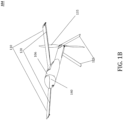
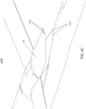
- FIG. 1B illustrates an example of a second configuration (e.g. deployed arrangement 104 ).
- a deployed arrangement 104 may be able sustain the higher aerodynamics loads associated with flight at a high airspeed or high-g pull-up maneuvers.
- at least one of the intermediary configurations e.g., the deployed arrangement 104
- the deployed arrangement may be used in a launch recovery, wherein the UAVDC has been launched and has not slowed to an airspeed that the third configuration can sustain.
- the deployed arrangement may be able to sustain high-speed flight more efficiently than the expanded arrangement.
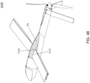
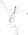
- FIG. 1C illustrates an example of a third configuration (e.g., an expanded arrangement 105 ).
- the UAVDC may be able to achieve an increased level of aerodynamic efficiency (i.e. flight endurance) as well as an increased payload weight capacity.
- the second configuration e.g., deployed arrangement 104
- the third configuration e.g., expanded arrangement 105
- the second configuration and the third configuration may be referred to as a common arrangement, but having wingspans that depend on the extent of the telescoped displacement of the wings.
- a UAVDC consistent with embodiments of the present disclosure may implement, but not be limited to, at least one of the following: wings 110 that may be configured to sweep and/or telescope, one or more trailing-edge hinged control surfaces that enable roll control (“ailerons") 120 , one or more fold-away actuating stabilizers 125 , one or more flexible aerodynamic fairings 130 , one or more propulsion mechanisms (e.g., fold-away propeller 135 ), and a modular payload 140.
- wings 110 that may be configured to sweep and/or telescope
- ailerons roll control
- fold-away actuating stabilizers 125 one or more flexible aerodynamic fairings 130
- propulsion mechanisms e.g., fold-away propeller 135
- the UAVDC may comprise intermediary configurations between the first configuration and second configuration or the second configuration and the third configuration.
- wings 110 may be at various stages of sweep or telescoping. It should be understood that the use of trailing-edge ailerons 120 and externally telescoped outer wing panels 310 may enable the UAVDC to continuously maintain controlled flight during transitions from the first configuration to the third configuration.
- the aforementioned wings 110 , stabilizers 125 , and propeller 135 may be stowed against a fuselage 106 of the UAVDC (i.e., folded and out of the way during vehicle launch).
- Fairing 130 may flex to accommodate wings 110 in their stowed configuration and then be configured to flex in a way so as to accommodate a sweeping motion of wings 110.
- the UAVDC may transform from the first configuration into the second configuration.
- wings 110 may be deployed by way of an outward sweeping motion (with fairing 130 flexing in a way to enable the sweeping motion).
- FIG. 2C illustrates an outward sweeping motion 250.
- outward sweeping motion 250 may be enabled by, but not limited to, for example, a sweeping gearbox coupled to an actuator.
- FIGs. 2A-2C illustrate an example of a sweeping gearbox 205 coupled to an actuator 210.
- sweeping motion 250 of wings 110 may enable configurable wing angles to optimize aerodynamics.
- Fairing 130 may be designed to accommodate wings 110 in the stored configuration as well as sweeping motion 250. Further, fairing 130 may close around wings 110 in order to maintain the aerodynamic integrity of the UAVDC, as shown in FIG. 4B .
- embodiments of the present disclosure may provide improvements over conventional systems.
- aircrafts that implement sweeping wings and wing angle adjustments require use of secondary mechanics to orient the wing angles.
- secondary mechanics add to weight and cost, as well as provide additional modes of failure.
- wings 110 may further be configured to telescope (i.e., expand in length) in the third configuration.
- Such telescoping wings may comprise a fixed inner section and one or more substantially hollow outer sections that slide along adjacent sections to provide a longer wingspan once deployed.
- FIG. 3 illustrates an example of telescoping wings 110 comprising a fixed inner section 305 that attaches to fuselage 106 and an outer section 310.
- a plurality of nested outer wing sections may be implemented.
- wings 110 may be stored in a compact arrangement 102 and later extend (i.e., telescope) to provide additional lift during the expanded arrangement 105.
- a telescoping mechanism consistent with embodiments of the present disclosure may employ, for example, a belt system 315 , a scissors mechanism, or a piston mechanism to extend and/or retract the wings.
- the telescoping means consistent with embodiments of the present disclosure enable a maximized wing span while maintaining roll control throughout the transition between configurations.
- the outer sections may comprise a substantially hollow interior so as to enable the fixed inner section to reside within the interior of the outer section.
- the outer section may then slide outwards (i.e., telescopes), away from fuselage 106 , thereby exposing the fixed inner section as it telescopes.
- the trailing-edge mounted control surfaces e.g., ailerons 120
- the trailing-edge mounted control surfaces are mounted to the outer section and are therefore exposed and operable throughout the deployment and telescoping process; in this way, the wingspan of the UAVDC can expand while continually maintaining controlled flight during the transition (e.g., regardless of the outer section position relative to the inner section position).
- inner section 305 connects to the fuselage 106
- outer section 310 may be telescoped outward from fuselage 106.
- Trailing-edge ailerons 120 may connect to outer section 310 to enable roll control. In this way, trailing-edge ailerons 120 may provide roll control even when wings 110 are not extended. Trailing-edge ailerons 120 may be connected by a hinge at a rear-most point of the wing in order to maximize an internal volume of the outer section 310 , which, in turn, maximizes the overall span of the wing 110 in its third configuration.
- other configurations of wing control surfaces such as spoilers, may be implemented within the spirit and scope of the present disclosure.
- a typical telescoping wing utilizes telescoping outer panels that are stored within the fixed inner panel, this precludes the use of ailerons mounted to the outer panels until the wing panels reach a telescoped state.
- conventional aileron implementations are configured within the wing surface itself, thereby reduce the amount of internal volume available in the wing. The reduced internal volume decreases the available depth of an interior wing section placement in a telescoping wing system, thereby leading to a smaller displacement in a telescoped configuration. In this way, conventional roll control surfaces may reduce the final length of a telescoped wing.
- Attaching trailing-edge hinged ailerons 120 to the outer section 310 of the telescoping wing 110 enables the inner section 305 of telescoping wing 110 to be stowed further within the interior of outer section 310 while still providing the necessary roll control to maintain flight in the deployed arrangement, before the wings are telescoped.
- the displacement of the outer section 310 is increased by a range greater than that of other telescoping wing systems, thereby leading to the benefits of increased wingspan over a conventional aerial vehicle capable of compact configurations.
- extending outer section 310 of the telescoping wing 110 from the fuselage further enables the trailing-edge hinged ailerons 120 to provide increased roll control of the UAVDC.
- control surfaces e.g., trailing-edge hinged ailerons 120
- the control surfaces may be operable in all of the UAVDC's configurations. That is, the control surfaces may be operable in the compact arrangement 102 , the deployed arrangement 104 , and in the expanded arrangement 105. Furthermore, the control surfaces may be operable during the transitionary phases between each of those arrangement.
- trailing-edge hinged ailerons 120 may be operable in between the first configuration (e.g., compact arrangement 102 ) and the deployed arrangement 104 (e.g., engaged in operation at approximately a 45-degree sweep) in order to provide post-launch stabilization for the UAVDC. Moreover, trailing-edge hinged ailerons 120 may be operable when the UAVDC is in the deployed arrangement 104 to provide flight control, as well as the transitionary stage between the deployed arrangement 104 and the expanded arrangement 105. Finally, trailing-edge hinged ailerons 120 may be operable in the expanded arrangement 105 to provide additional, more effective flight control.
- first configuration e.g., compact arrangement 102
- the deployed arrangement 104 e.g., engaged in operation at approximately a 45-degree sweep
- trailing-edge hinged ailerons 120 may be operable when the UAVDC is in the deployed arrangement 104 to provide flight control, as well as the transitionary stage between the deployed arrangement 104 and the expanded arrangement 105.
- One or more stabilizers 125 of the UAVDC may be deployed in the intermediary configurations, second configuration, and/or the third configuration.
- stabilizers 125 may be deployed upon interfacing with air resistance. For example, when stabilizers 125 interface with an airstream, a resulting drag force may cause stabilizers 125 to move into a deployed configuration.
- Servos may actuate the stabilizers 125 once stabilizers 125 are deployed.
- Deployable control surfaces embodied in the present disclosure as stabilizers 125 , are improved over conventional systems, for example, by enabling automatic deployment without requiring controlling components (e.g., actuators and linkages) to adjust. Further, by implementing a flexible fairing, the aerodynamic efficiencies may be improved. It should be understood that not all embodiments of the UAVDC may comprise each of the aforementioned components, while other embodiments of the UAVDC may comprise additional components, and yet other embodiments still may comprise various combinations of the embodiments described in the present disclosure.
- Propeller 135 of the UAVDC may deploy upon interfacing with the air resistance.
- springs and/or centripetal force from a rotation of propeller 135 may be implemented in deploying propeller 135.
- a UAVDC consistent with embodiments of the present disclosure may be configured to receive a modular payload 140.
- modular payload 140 may remain fixed in both the first and second configuration.
- modular payload 140 may be configured into the UAVDC, serving as a nose of fuselage 106.
- Embodiments of the present disclosure may provide improvements over conventional unmanned aerial vehicles including, but not limited to the following examples:
- FIG. 1C illustrates an UAVDC consistent with embodiments of the present disclosure.
- Embodiments of the present disclosure may comprise a fuselage 106 , one or more antennas 705 , power source 1310 , wings 110 that may be configured to sweep and/or telescope, stabilizers 125 , and payload 140 .
- Further embodiments may comprise a propulsion mechanism, such as, for example, propeller 135 .
- Fuselage 106 may be comprised of, but not limited to, for example, carbon fiber. Further, fuselage 106 may be comprised of, but not limited to, for example, a composite material (e.g., fiberglass, Kevlar, Spectra). In various embodiments, plastics may be used, including, but not limited to 3D printed plastics. Fuselage 106 may take an aerodynamic configuration to facilitate speed and reduced air resistance.
- a composite material e.g., fiberglass, Kevlar, Spectra
- plastics may be used, including, but not limited to 3D printed plastics. Fuselage 106 may take an aerodynamic configuration to facilitate speed and reduced air resistance.
- the UAVDC may be configured with various propulsion mechanisms, and that propeller 135 is just one illustrated variation.
- Other propulsion mechanisms may include, but are not limited to, rockets, jet engines and compressed gas jets.
- no propulsion may be required at all, as the UAVDC may have characteristics of a glider.
- the UAVDC may be launched from, for example, a tube or released from, for example, an airplane within gliding range of its mission target.
- the various properties of the UAVDC as described in various embodiments herein, may provide the UAVDC with sufficient flight time to accomplish its mission without requiring additional propulsion.
- propeller 135 is shown as having two propeller blades, it should be understood that more or fewer propeller blades may be utilized. For example, only a single propeller blade may be used.
- propeller 135 may be configured at different positions of the UAVDC.
- propeller 135 may mount to the front of the UAVDC instead of the rear.
- the UAVDC may have a wing arrangement comprised of a single wing with two wing sections.
- the wing arrangement may be segmented in a left wing section and a right wing section to enable variable sweep at approximately a lateral plane of symmetry between the left wing section and the right wing section.
- the wing sections may be a left wing and a right wing (e.g., wings 110 ). Still consistent with embodiments of the present disclosure, however, the wing arrangement may be a single wing comprised of the two wing sections.
- the wing arrangement being configurable in a first arrangement (e.g., corresponding to the first configuration of the UAVDC), a second arrangement (e.g., corresponding to the second or third configuration of the UAVDC), and a third arrangement.
- first arrangement e.g., corresponding to the first configuration of the UAVDC
- second arrangement e.g., corresponding to the second or third configuration of the UAVDC
- third arrangement may comprise the wing sections at any wing deployment angle in between the first sweep deployment angle and the second sweep deployment angle.
- the UAVDC may comprise a sweeping gearbox configured to pivot the left wing section and the right wing section to enable the wing arrangement to sweep from the first arrangement to the second arrangement at any sweep deployment angle.
- the UAVDC may comprise an actuator coupled to the sweeping gearbox configured to actuate the sweeping of the wing arrangement at any sweep deployment angle.
- fairing 130 may be configured to change from an open configuration to a closed configuration.
- Fairing 130 may begin in an open configuration by flexing to allow the first wing section and the second wing section to be stowed under the fairing in the first arrangement, and move to a closed configuration to provide aerodynamic and/or environmental advantages in the second arrangement.
- the wings 110 may be stowed in a launch configuration as shown in first configuration 102.
- the launch configuration of wings 110 may comprise a vertical offset.
- Wings 110 may be swept to a flight configuration by sweeping gearbox 205 (e.g., a sweeping means).
- actuator 210 attached to sweeping gearbox 205 may comprise a worm gear 220 coupled to each wing and a worm 225 coupled to worm gears 220 and configured to spread the wings in sweeping motion 250. Sweeping gearbox 205 may sit on wing mount 215.
- Various other means may be used in sweeping wings 110 , including, but not limited to, springs.
- wings 110 may not need to be fully swept in order to enable flight.
- the UAVDC may be capable of flight at an angle less than full sweep.
- Gearbox 205 may be configured such that wings 110 may be stored in the launch configuration with a first set of angles with respect to each other (e.g., flat with respect to each other) and with respect to the fuselage (e.g., flat with respect to the fuselage). Gearbox 205 may further be configured to cause wings 110 to be deployed with optimal incidence angles and dihedral angles in the swept configuration. This may be achieved by orienting each wing's axis of rotation as well as each wing's attachment to worm gear 220 (or "wing pivot"). As such, gearbox 205 may comprise two pivot axes around which the wings may sweep.
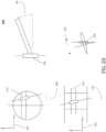
- FIG. 2D illustrates a schematic for illustrating geometry to enable a gearbox 205.
- the axis of rotation may be oriented such that its angle in the Y-Z plane 270 , as shown in reference to axes 255 , may match an angle of attachment 265 to worm gear 220. Further the angle in the X-Z plane 260 may match an angle of attachment 275 to worm gear 220.
- wings 110 may be stowed flat with respect to each other and with respect to the fuselage, while deployed with optimal dihedral and incidence angles.
- the optimal dihedral angle may be the combination of the angle in the X-Z plane 260 and the angle of attachment 265 ; the optimal angle of incidence may be the combination of the angle in the X-Y plane and the angle of attachment 275.
- a single mechanism may both sweep wings 110 and orient wings 110 to desired dihedral angles and angles of incidence.
- the single mechanism for sweeping and orienting wings may reduce weight and complexity, thus increasing endurance and decreasing cost.
- the UAVDC may comprise fairing 130 to reduce drag while enabling the outward sweeping motion 250 of wings 110.
- FIGs. 11A and 11B illustrate fairing 130 in a first configuration 1105 and a second configuration 1110 , respectively.
- Fairing 130 may be made of a flexible material (e.g., fiberglass) such that it may bend out of the way as wings 110 sweep. In various embodiments, other materials may be used, including, but not limited to carbon fiber, Kevlar, and sheet metal. Fairing 130 may comprise wing hole cutouts 1115 to fit around wings 110 's profile as wings 110 reach second configuration 1110.
- fairing 130 in first configuration 1105 may be resting upon the sweeping wings 110 in compact arrangement 102 and undergoing tension from being held in a strained ("buckled") state.
- Slits 1120 may be implemented in fairing 130 to enable fairing 130 to flex adequately to accommodate sweeping wings 110 in compact arrangement 102.
- fairing 130 may flex as illustrated in FIG. 4B to close around the wing as wings 110 reach wing hole cutouts 1115.
- fairing 130 may be in an unstrained state as it securely fits around wing 110 to minimize drag.
- fairing 130 comprises a fibrous composite material, it may be desirable to use a fiber orientation to facilitate buckling and flexibility in the laminate (e.g. using +/-45 degree plies may exhibit greater flexibility and buckle easily in 0 and 90 degree directions).
- magnets 1125 may be employed to further lock fairing 130 around the swept wings 110 , as shown in FIG. 4C .
- Magnets 1125 may be located on fuselage 106.
- Magnets of opposite polarity or a magnetic metal 1130 may be on fairing 130 to receive magnets 1125's magnetic attraction.
- the location of the magnets 1125 and corresponding magnetic metal 1130 may be reversed.
- wings 110 may telescope.
- inner section 305 may attach to fuselage 106 of the UAVDC.
- Inner section 305 may be stowed at least partially within outer section 310 during the compact first configuration.
- Outer section 310 may comprise a substantially hollow interior.
- An exterior surface of interior section 305 may be stowed against and interior surface of the exterior section 310.
- outer section 310 may slide along inner section 305 to extend outwards from the fuselage 106.
- an increasing portion of inner section 305 may be exposed.
- the wingspan of wings 110 may be approximately the length of outer section 310 and the exposed portion of interior section 305.
- Both inner section 305 and outer section 310 may employ an aerodynamic profile to provide lift during flight.
- Some embodiments may utilize belt system 315 for telescoping wings 110.
- belt system 315 may comprise belt pulleys 325 , which may attach to the inner wing section 305 ("second section"). At least one pulley 325 may be driven by an actuator 320. In further embodiments, a plurality of pulleys 325 may be driven by a plurality of actuators 320. Belt 330 may loop around pulleys 325. Notches in belt 330 may enable actuator 320 to move belt 330.
- One of the straight lengths 331 of belt 330 may be contained within the inner wing section 305 , while the other length 332 of belt 330 may be contained in a groove on the bottom of the inner wing section 305 ("second section") that is exposed to the outer wing section 310 ("first section") prior to the telescoping of wings 110.
- belt 330 may be attached to at least a portion of outer wing section 310 along length 332.
- actuator 320's rotation not only causes a movement of belt 330 but also a displacement of outer wing section 310 due to its attachment to belt 330. Accordingly, actuation in direction 335 would cause section 310 to be extended outward from the fuselage 106 , thereby increasing the wingspan of the UAVDC.
- inner section 305 is simultaneously withdrawn from the interior of outer section 310 , increasing the wingspan of the UAVDC. Accordingly, as wings 110 are telescoped, length 332 may become exposed but the groove may prevent the belt 330 from protruding from the bottom of the exposed inner wing section 305.
- Attaching outer section 310 to length 332 may be implemented by, for example, but not limited to, a clamp, screw or adhesive.
- belt 330 may comprise a length of fiber-reinforced rubber material. By stripping rubber from each end of the belt to expose fibers, further attachment mechanisms for attaching belt 330 to outer section 310 may be available.
- the exposed fibers may be tied to the outer wing section 310 (e.g., to holes in outer wing section 310 ).
- the tied fibers may further be secured, for example, with an adhesive. In this way, ends of belt 330 may be attached to create a connected loop without the use of a coupler clamping the ends, thereby eliminating bulky parts commonly used in the art.
- belt system 315 may provide a lighter and/or a more compact mechanism for telescoping over conventional telescoping systems.
- the telescoping of the wings may be reversed by reversing direction 335 of actuator 320 to retract wings 110.
- components of belt system 315 may be reversed, such that outer wing section 310 may be affixed to fuselage 106 and inner wing section 305 may be telescoped outward.
- a similar belt system may be implemented for extending a boom from fuselage 106. For example, instead of attaching belt 330 to outer wing section 310 , belt 330 may attach to the boom.
- wings 110 comprise ailerons 120.
- ailerons 120 may be attached via a hinge 1215 to the trailing edge of outer section 310.
- ailerons 120 may minimize interference with outer section 310's internal volume as compared to conventional ailerons.
- inner section 305 may have an optimized profile and an increased span that would otherwise be limited by the more commonly-used ailerons.
- inner section 305 may, when stowed within the first compact configuration, overlap at least a portion of the length of the trailing edge aileron attachment to outer section 310. In this way, a ratio of the surface area between the inner section 305 and outer section 310 may be increased. Maximizing wing span can significantly increase airframe efficiency, flight endurance, and payload capacity. Hinge types that may enable such trailing edge ailerons 120 include, but are not limited to, a living hinge, or other flexure bearing.
- ailerons 120 may enable roll control throughout the wing deployment phase. This means the UAVDC may be flown with positive roll control regardless of outer section 310 's position relative to inner section 305 , which can be beneficial during launch and flight recovery phases where transition to stable flight can be carried out with lower structural loads on the air frame when the wings are configured in their non-telescoped position. This may also be beneficial as the span may be reduced or increased in flight, to maximize aerodynamic efficiency without losing roll control.
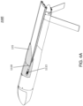
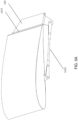
- FIG. 5A shows a configuration of components for controlling the ailerons. Each aileron 120 may be positioned by a servo 1320 , as illustrated in FIG.
- Each servo 1320 may, in some embodiments, be positioned within outer wing section 310. In further embodiments, ailerons 120 may be operated by other means, including, but not limited to, gears or shafts. Each servo 1320 may be controlled by controller 1500.
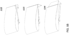
- FIG. 5B illustrates possible configurations for ailerons 120 , including, but not limited to, a tucked position 1230 , which minimizes stowed volume, a partially folded position 1235 , and a fully deployed position 1240.
- Servo 1320 may be operated through a control wire positioned within outer wing section 310 and inner wing section 305.
- the control wire may extend from fuselage 106 via inner wing section 305.
- An end of wing section 305 may comprise an opening through which the control wire may extend into the interior of outer wing section 310 , connecting to servo 1320.
- the wire may comprise sufficient length to accommodate the telescoping of the wings. While the wings are not telescoped, the control wire may be spooled or neatly folded within either of the wing sections.
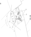
- FIG. 6 illustrates one example of internal configuration of the UAVDC in which a power source 1310 may be positioned within the interior of fuselage 106.
- Power source 1310 may comprise, for example, a fuel tank or one or more batteries.
- Various components of the UAVDC may be connected to power source 1310 , including, but not limited to, modular payload 140 , controller 1500 , sweeping gearbox actuator 210 , control mechanisms for ailerons (e.g., servos 1320 ), servos 410 for stabilizers 125 , a motor 1315 to drive the propeller 135 , and antenna 705.
- Embodiments of the UAVDC comprising a propulsion device may be powered by alternative power sources, such as, for example, an internal combustion engine.
- a fuel source for the internal combustion engine e.g., gas tank
- a fuel source for the internal combustion engine may be positioned within interior 1305 of fuselage 106.
- Internal components may further include, for example, but not be limited to, the following components: sweeping gearbox 205 and actuator 210 employed to sweep wings 110 ; control mechanisms for ailerons 120 (e.g., servos 1320 ) for operating ailerons 120 and servos 410 for operating stabilizers 125 ); a motor 1315 for driving propeller 135 ; driveshaft 1330 for coupling motor 1315 to propeller 135 and an on-board controller 1500 for controlling the deployment, flight, and operation of the UAVDC.
- the illustrated configuration of internal components is just one possible configuration, and other embodiments are possible.
- the interior components may be distributed to balance the weight in an optimal way for flight.
- the UAVDC may be fired from a tube launched from a craft or dropped from a carrier aerial vehicle.
- the compact arrangement 102 of the UAVDC's first configuration (as specified, for example, with reference to FIG. 1A ) may enable the UAVDC to be tube-launched as, for example, a missile.
- the UAVDC once dropped from a carrier aerial vehicle, the UAVDC may be aerodynamically designed (as illustrated) and with such a weight distribution that it may self-orient from a tumbling drop into a dive.
- the stabilizers 125 and propeller 135 may deploy.
- Controller 1500 may automatically engage actuators and the wing deployment mechanisms instantly or after a set amount of time has passed since the launch. In other embodiments, engagement may occur upon certain reading from on-board sensors (e.g., including, but not limited to, sensors deployed in modular payload 140 ). For example, wing deployment and extension may be dependent on certain in-flight factors such as, for example, velocity, acceleration, and leveling of the UAVDC. Controller 1500 may be configured to trigger deployment of various components upon the satisfaction of certain pre-set conditions. Such conditions may be defined prior to deployment.
- Actuator 210 may drive sweeping gearbox 205 to sweep wings 110.
- the UAVDC may be capable of controlling sustained flight once wings 110 sweep out 45 degrees.
- wings 110 may move within wing hole cutouts 1115 of fairing 130 , which has opened due to the strain of the sweeping motion 250 , and relocked with the aid of magnets positioned within the fuselage.
- fairing 130 may automatically snap shut around the profile of wings 110 to improve aerodynamics.
- Magnets 1125 may further lock fairing 130 around wings 110.
- wings 110 may begin telescoping.
- belt system 315 may pull outer section 310 along inner section 305 to telescope wings 110.
- the wing sweep angles and telescoped positions may further be dynamically adjusted in flight.
- modular payload 140 may deploy from its first arrangement to its second arrangement.
- modular payload 140 may comprise a plurality of sensing devices better situated for performance at a deployed position (e.g., an extended boom). Such deployment may occur upon the post-launch stabilization segment of the UAVDC's flight.
- the operator may control the operation of the UAVDC during the mission.
- the operator may be able to control the flight components, including, but not limited to, the wing deployment mechanisms (e.g., sweeping gearbox 205 , actuator 210 , and belt system 315 ), propeller 135 , stabilizers 125 , ailerons 120 , and further deployable components.
- on-board controller 1500 may be pre-configured with mission control data.
- Embodiments of the UAVDC may be used for a plurality of missions including, but not limited to, data capture, payload deployment, and providing a telecommunications relay.
- embodiments of the UAVDC may be controlled in data capture and transmission.
- the UAVDC may enable the operator to release modular payload 140 .
- the mission may be terminated by flying the UAVDC to a recapture location where it may be recovered. Further, the UAVDC may terminate a mission by crash landing. For example, the UAVDC may be flown into rocks or a hard surface in order to destroy functional components. In further embodiments, the UAVDC maybe equipped with an explosive device such that it may be self-destructed upon mission completion.
Description
- The present disclosure generally relates to unmanned aerial vehicles.
- Unmanned aerial vehicles may be used for a plurality of applications. Such applications comprise commercial applications including surveillance and filming, and for military applications, reconnaissance and tactical missions. In certain circumstances, compact configurations can be beneficial to enabling particular types of missions. For example, compact configurations reduce space and enable various deployment options. However, current compact configurations are limited in flight range, endurance, and payload capacity.
-
US 2011/001016 discloses an aircraft wing including a stationary root section and a telescoping end section slideable in the span wise direction. The telescoping end section can either slide within or slide over the root section as it extends and retracts during flight. The aircraft wing can also include a second telescoping distal end section, and can sweep back during flight, while the end sections or distal end sections are extended or retracted. -
US 2009/206193 discloses a wing including coaxially disposed first and second elongated airfoils and an inflatable device arranged to move the first airfoil coaxially relative to the second airfoil. The second airfoil has a root end fixed to the vehicle and an opposite outboard end, and the first airfoil is arranged to move axially between a retracted position generally inboard of the outboard end of the second airfoil and a deployed position generally outboard thereof. When the movable airfoil is deployed, a latching mechanism locks it in position. -
US 2010/148011 discloses a telescoping structure including an alignment mechanism to keep aligned an inner structure member and outer structure member, as the members translate relative to one another to extend or retract the telescoping structure. - According to the present invention there is provided a telescoping wing system according to claim 1.
- Further embodiments of the telescopic wing system are provided according to the appended dependent claims 2-13.
- Both the foregoing brief overview and the following detailed description provide examples and are explanatory only. Accordingly, the foregoing brief overview and the following detailed description should not be considered to be restrictive. Further, features or variations may be provided in addition to those set forth herein. For example, embodiments may be directed to various feature combinations and sub-combinations described in the detailed description.
- The accompanying drawings explain certain embodiments of the present disclosure. This text is included for illustrative, non-limiting, explanatory purposes of certain embodiments detailed in the present disclosure. In the drawings:
-
FIG. 1A illustrates an unmanned aerial vehicle with deployable components in a first configuration; -
FIG. 1B illustrates the unmanned aerial vehicle with deployable components in a second configuration; -
FIG. 1C illustrates the unmanned aerial vehicle with deployable components in a third configuration; -
FIG. 2A illustrates a cut-away view of a sweeping gearbox coupled to an actuator; -
FIG. 2B illustrates a view of the sweeping gearbox; -
FIG. 2C illustrates another view of the sweeping gearbox and a direction of wing sweeping; -
FIG. 2D illustrates a set of schematic drawings for enabling the sweeping gearbox to allow wings to have dihedral and incidence when deployed and to lay flat while stowed; -
FIG. 3 illustrates an example of telescoping wings; -
FIG. 4A illustrates a fairing in a first configuration; -
FIG. 4B illustrates the fairing in a second configuration; -
FIG. 4C illustrates the fairing comprising magnets; -
FIG. 5A illustrates components for controlling ailerons; -
FIG. 5B illustrates a plurality of configurations for the ailerons; and -
FIG. 6 illustrates one example of internal configuration of the UAVDC. - This overview is provided to introduce a selection of concepts in a simplified form that are further described below. This overview is not intended to identify key features or essential features of the claimed subject matter. Nor is this overview intended to be used to limit the claimed subject matter's scope.
- An improved unmanned aerial vehicle with deployable components (UAVDC) is provided in the various embodiments disclosed herein. Various aspects of the UAVDC lead to improvements over conventional unmanned aerial vehicles, including, but not limited to, for example, improved portability, deployment, post-deployment transition to flight control, aerodynamic efficiency and flight endurance, payload capacity, and maximized mission capability over conventional unmanned aerial vehicles. As will be detailed below, the UAVDC of the present disclosure includes a number of features that lead to the aforementioned improvements, including, but not limited to, for example, trailing-edge hinged ailerons, deployable stabilizers, gearbox, fairing, and sweeping and telescoping wing implementations.
- The UAVDC may be configured in a plurality of arrangements. A first configuration may be a compact arrangement suitable in, for example, storage and launching embodiments, while a second configuration may be a deployed arrangement suitable in, for example, launch recovery and flight, and a third configuration may be an expanded configuration suitable in, for example, high-endurance flight. As will be detailed below, the UAVDC may be fully functional and operable in intermediary configurations between these three configurations to provide some of the advantages of the improved UAVDC at higher airspeeds.
-
FIG. 1A illustrates an example of a first configuration (e.g., compact arrangement 102).Compact arrangement 102 may enable convenient storage and transportation of the UAVDC. In addition,compact arrangement 102 may enable certain launch methods, such as a launch from, for example, a tube or a release from, for example, an aircraft's weapons/bomb bay or wing attachment. - Consistent with embodiments of the present disclosure, the UAVDC may be deployed after launch into the deployed arrangement that is suitable to survive the high aerodynamic loads of launch recovery and high-speed flight. During the flight, the UAVDC may be further deployed into the expanded arrangement that is suitable for efficient, long-endurance flight. It should be understood that the term "deploy" and "deployment" may refer to the deployable components moving from one UAVDC configuration to another.
-
FIG. 1B illustrates an example of a second configuration (e.g. deployed arrangement 104). By using a deployedarrangement 104, embodiments may be able sustain the higher aerodynamics loads associated with flight at a high airspeed or high-g pull-up maneuvers. In this way, at least one of the intermediary configurations (e.g., the deployed arrangement 104) may be used in a launch recovery, wherein the UAVDC has been launched and has not slowed to an airspeed that the third configuration can sustain. Furthermore, the deployed arrangement may be able to sustain high-speed flight more efficiently than the expanded arrangement. -
FIG. 1C illustrates an example of a third configuration (e.g., an expanded arrangement 105). By using the expanded arrangement the UAVDC may be able to achieve an increased level of aerodynamic efficiency (i.e. flight endurance) as well as an increased payload weight capacity. In various embodiments, the second configuration (e.g., deployed arrangement 104) and the third configuration (e.g., expanded arrangement 105) may be referred to as a common arrangement, but having wingspans that depend on the extent of the telescoped displacement of the wings. - As will be detailed below, during transformation from
compact arrangement 102 to expandedarrangement 105, a UAVDC consistent with embodiments of the present disclosure may implement, but not be limited to, at least one of the following:wings 110 that may be configured to sweep and/or telescope, one or more trailing-edge hinged control surfaces that enable roll control ("ailerons") 120, one or more fold-away actuating stabilizers 125, one or more flexibleaerodynamic fairings 130, one or more propulsion mechanisms (e.g., fold-away propeller 135), and amodular payload 140. - In further embodiments, the UAVDC may comprise intermediary configurations between the first configuration and second configuration or the second configuration and the third configuration. In the intermediary configurations,
wings 110 may be at various stages of sweep or telescoping. It should be understood that the use of trailing-edge ailerons 120 and externally telescopedouter wing panels 310 may enable the UAVDC to continuously maintain controlled flight during transitions from the first configuration to the third configuration. - In the first configuration, prior to deployment, the
aforementioned wings 110,stabilizers 125, andpropeller 135 may be stowed against afuselage 106 of the UAVDC (i.e., folded and out of the way during vehicle launch). Fairing 130 may flex to accommodatewings 110 in their stowed configuration and then be configured to flex in a way so as to accommodate a sweeping motion ofwings 110. Once launched, the UAVDC may transform from the first configuration into the second configuration. In the second configuration,wings 110 may be deployed by way of an outward sweeping motion (with fairing 130 flexing in a way to enable the sweeping motion).FIG. 2C illustrates an outwardsweeping motion 250. As will be further detailed below, outwardsweeping motion 250 may be enabled by, but not limited to, for example, a sweeping gearbox coupled to an actuator.FIGs. 2A-2C illustrate an example of asweeping gearbox 205 coupled to anactuator 210. Further,sweeping motion 250 ofwings 110 may enable configurable wing angles to optimize aerodynamics. Fairing 130 may be designed to accommodatewings 110 in the stored configuration as well assweeping motion 250. Further, fairing 130 may close aroundwings 110 in order to maintain the aerodynamic integrity of the UAVDC, as shown inFIG. 4B . - By implementing a
gearbox 205 configured to sweepwings 110 as well as orientwings 110 with optimal dihedral angles 265 and angles ofincidence 275, embodiments of the present disclosure may provide improvements over conventional systems. For example, in conventional systems, aircrafts that implement sweeping wings and wing angle adjustments require use of secondary mechanics to orient the wing angles. Such secondary mechanics add to weight and cost, as well as provide additional modes of failure. - Still consistent with embodiments of the present disclosure,
wings 110 may further be configured to telescope (i.e., expand in length) in the third configuration. Such telescoping wings may comprise a fixed inner section and one or more substantially hollow outer sections that slide along adjacent sections to provide a longer wingspan once deployed.FIG. 3 illustrates an example oftelescoping wings 110 comprising a fixedinner section 305 that attaches tofuselage 106 and anouter section 310. In further embodiments, a plurality of nested outer wing sections may be implemented. In this way,wings 110 may be stored in acompact arrangement 102 and later extend (i.e., telescope) to provide additional lift during the expandedarrangement 105. As will be detailed below, a telescoping mechanism ("telescoping means") consistent with embodiments of the present disclosure may employ, for example, abelt system 315, a scissors mechanism, or a piston mechanism to extend and/or retract the wings. - The telescoping means consistent with embodiments of the present disclosure enable a maximized wing span while maintaining roll control throughout the transition between configurations. For example, as the inner section is fixed, the outer sections may comprise a substantially hollow interior so as to enable the fixed inner section to reside within the interior of the outer section. The outer section may then slide outwards (i.e., telescopes), away from
fuselage 106, thereby exposing the fixed inner section as it telescopes. The trailing-edge mounted control surfaces (e.g., ailerons 120) are mounted to the outer section and are therefore exposed and operable throughout the deployment and telescoping process; in this way, the wingspan of the UAVDC can expand while continually maintaining controlled flight during the transition (e.g., regardless of the outer section position relative to the inner section position). - In some embodiments,
inner section 305 connects to thefuselage 106, whileouter section 310 may be telescoped outward fromfuselage 106. Trailing-edge ailerons 120 may connect toouter section 310 to enable roll control. In this way, trailing-edge ailerons 120 may provide roll control even whenwings 110 are not extended. Trailing-edge ailerons 120 may be connected by a hinge at a rear-most point of the wing in order to maximize an internal volume of theouter section 310, which, in turn, maximizes the overall span of thewing 110 in its third configuration. In various embodiments, other configurations of wing control surfaces, such as spoilers, may be implemented within the spirit and scope of the present disclosure. - By implementing hollow outer
telescoping wing section 310 and trailing-edge hingedaileron 120, a plurality of improvements are introduced. A typical telescoping wing utilizes telescoping outer panels that are stored within the fixed inner panel, this precludes the use of ailerons mounted to the outer panels until the wing panels reach a telescoped state. Furthermore, conventional aileron implementations are configured within the wing surface itself, thereby reduce the amount of internal volume available in the wing. The reduced internal volume decreases the available depth of an interior wing section placement in a telescoping wing system, thereby leading to a smaller displacement in a telescoped configuration. In this way, conventional roll control surfaces may reduce the final length of a telescoped wing. - Attaching trailing-edge hinged
ailerons 120 to theouter section 310 of thetelescoping wing 110 enables theinner section 305 of telescopingwing 110 to be stowed further within the interior ofouter section 310 while still providing the necessary roll control to maintain flight in the deployed arrangement, before the wings are telescoped. In turn, whenwings 110 are telescoped, the displacement of theouter section 310 is increased by a range greater than that of other telescoping wing systems, thereby leading to the benefits of increased wingspan over a conventional aerial vehicle capable of compact configurations. Further still, extendingouter section 310 of thetelescoping wing 110 from the fuselage further enables the trailing-edge hingedailerons 120 to provide increased roll control of the UAVDC. - Consistent with embodiments of the present disclosure, the control surfaces (e.g., trailing-edge hinged ailerons 120) may be operable in all of the UAVDC's configurations. That is, the control surfaces may be operable in the
compact arrangement 102, the deployedarrangement 104, and in the expandedarrangement 105. Furthermore, the control surfaces may be operable during the transitionary phases between each of those arrangement. - For example, trailing-edge hinged
ailerons 120 may be operable in between the first configuration (e.g., compact arrangement 102) and the deployed arrangement 104 (e.g., engaged in operation at approximately a 45-degree sweep) in order to provide post-launch stabilization for the UAVDC. Moreover, trailing-edge hingedailerons 120 may be operable when the UAVDC is in the deployedarrangement 104 to provide flight control, as well as the transitionary stage between the deployedarrangement 104 and the expandedarrangement 105. Finally, trailing-edge hingedailerons 120 may be operable in the expandedarrangement 105 to provide additional, more effective flight control. - One or
more stabilizers 125 of the UAVDC may be deployed in the intermediary configurations, second configuration, and/or the third configuration. In further embodiments,stabilizers 125 may be deployed upon interfacing with air resistance. For example, whenstabilizers 125 interface with an airstream, a resulting drag force may causestabilizers 125 to move into a deployed configuration. Servos may actuate thestabilizers 125 oncestabilizers 125 are deployed. - Deployable control surfaces, embodied in the present disclosure as
stabilizers 125, are improved over conventional systems, for example, by enabling automatic deployment without requiring controlling components (e.g., actuators and linkages) to adjust. Further, by implementing a flexible fairing, the aerodynamic efficiencies may be improved. It should be understood that not all embodiments of the UAVDC may comprise each of the aforementioned components, while other embodiments of the UAVDC may comprise additional components, and yet other embodiments still may comprise various combinations of the embodiments described in the present disclosure. -
Propeller 135 of the UAVDC may deploy upon interfacing with the air resistance. In further embodiments, springs and/or centripetal force from a rotation ofpropeller 135 may be implemented in deployingpropeller 135. - A UAVDC consistent with embodiments of the present disclosure may be configured to receive a
modular payload 140. In some embodiments,modular payload 140 may remain fixed in both the first and second configuration. By way of non-limiting example,modular payload 140 may be configured into the UAVDC, serving as a nose offuselage 106. - Embodiments of the present disclosure may provide improvements over conventional unmanned aerial vehicles including, but not limited to the following examples:
- Improved aerodynamic efficiency which increases flight endurance;
- Increased payload capacity;
- Launch and transition to flight without the assistance of external aerodynamic treatments such as a parachute or balloon; and
- Maximized mission capability (i.e. its modular payload and reconfigurable and highly efficient airframe enable the UAVDC to efficiently perform a wider array of missions such as, for example, but not limited to, Intelligence Surveillance Reconnaissance (ISR), Signals Intelligence (SIGINT), weather, geophysical, environmental, and the like.
- Both the foregoing overview and the following detailed description provide examples and are explanatory only. Accordingly, the foregoing overview and the following detailed description should not be considered to be restrictive. Further, features or variations may be provided in addition to those set forth herein. For example, embodiments may be directed to various feature combinations and sub-combinations described in the detailed description.
-
FIG. 1C illustrates an UAVDC consistent with embodiments of the present disclosure. Embodiments of the present disclosure may comprise afuselage 106, one or more antennas 705,power source 1310,wings 110 that may be configured to sweep and/or telescope,stabilizers 125, andpayload 140. Further embodiments may comprise a propulsion mechanism, such as, for example,propeller 135. -
Fuselage 106 may be comprised of, but not limited to, for example, carbon fiber. Further,fuselage 106 may be comprised of, but not limited to, for example, a composite material (e.g., fiberglass, Kevlar, Spectra). In various embodiments, plastics may be used, including, but not limited to 3D printed plastics.Fuselage 106 may take an aerodynamic configuration to facilitate speed and reduced air resistance. - It should be understood that the UAVDC may be configured with various propulsion mechanisms, and that
propeller 135 is just one illustrated variation. Other propulsion mechanisms may include, but are not limited to, rockets, jet engines and compressed gas jets. Moreover, in some embodiments, no propulsion may be required at all, as the UAVDC may have characteristics of a glider. In such embodiments, the UAVDC may be launched from, for example, a tube or released from, for example, an airplane within gliding range of its mission target. The various properties of the UAVDC, as described in various embodiments herein, may provide the UAVDC with sufficient flight time to accomplish its mission without requiring additional propulsion. - While
propeller 135 is shown as having two propeller blades, it should be understood that more or fewer propeller blades may be utilized. For example, only a single propeller blade may be used. - Although many of the figures illustrate
propeller 135 in a rear-mounted position, it should be understood that, in embodiments where a propulsion mechanism is provided,propeller 135 may be configured at different positions of the UAVDC. For example, in some embodiments,propeller 135 may mount to the front of the UAVDC instead of the rear. - Referring back to
FIG. 1A , the UAVDC may have a wing arrangement comprised of a single wing with two wing sections. The wing arrangement may be segmented in a left wing section and a right wing section to enable variable sweep at approximately a lateral plane of symmetry between the left wing section and the right wing section. In some embodiments, the wing sections may be a left wing and a right wing (e.g., wings 110). Still consistent with embodiments of the present disclosure, however, the wing arrangement may be a single wing comprised of the two wing sections. - The wing arrangement being configurable in a first arrangement (e.g., corresponding to the first configuration of the UAVDC), a second arrangement (e.g., corresponding to the second or third configuration of the UAVDC), and a third arrangement. In the first arrangement, the left wing section and the right wing section may be stowed against the fuselage at a first sweep deployment angle. In the second arrangement, the wing arrangement may be fully deployed for flight at a second sweep deployment angle. A third arrangement may comprise the wing sections at any wing deployment angle in between the first sweep deployment angle and the second sweep deployment angle.
- To enable the sweep deployment angle, the UAVDC may comprise a sweeping gearbox configured to pivot the left wing section and the right wing section to enable the wing arrangement to sweep from the first arrangement to the second arrangement at any sweep deployment angle. The UAVDC may comprise an actuator coupled to the sweeping gearbox configured to actuate the sweeping of the wing arrangement at any sweep deployment angle.
- Throughout the sweeping motion, fairing 130 may be configured to change from an open configuration to a closed configuration. Fairing 130 may begin in an open configuration by flexing to allow the first wing section and the second wing section to be stowed under the fairing in the first arrangement, and move to a closed configuration to provide aerodynamic and/or environmental advantages in the second arrangement.
- The
wings 110 may be stowed in a launch configuration as shown infirst configuration 102. In some embodiments, the launch configuration ofwings 110 may comprise a vertical offset.Wings 110 may be swept to a flight configuration by sweeping gearbox 205 (e.g., a sweeping means). For example,actuator 210 attached tosweeping gearbox 205 may comprise aworm gear 220 coupled to each wing and aworm 225 coupled toworm gears 220 and configured to spread the wings insweeping motion 250.Sweeping gearbox 205 may sit onwing mount 215. Various other means may be used insweeping wings 110, including, but not limited to, springs. In some embodiments,wings 110 may not need to be fully swept in order to enable flight. For example, the UAVDC may be capable of flight at an angle less than full sweep. -
Gearbox 205 may be configured such thatwings 110 may be stored in the launch configuration with a first set of angles with respect to each other (e.g., flat with respect to each other) and with respect to the fuselage (e.g., flat with respect to the fuselage).Gearbox 205 may further be configured to causewings 110 to be deployed with optimal incidence angles and dihedral angles in the swept configuration. This may be achieved by orienting each wing's axis of rotation as well as each wing's attachment to worm gear 220 (or "wing pivot"). As such,gearbox 205 may comprise two pivot axes around which the wings may sweep.FIG. 2D illustrates a schematic for illustrating geometry to enable agearbox 205. For example, the axis of rotation may be oriented such that its angle in theY-Z plane 270, as shown in reference toaxes 255, may match an angle of attachment 265 toworm gear 220. Further the angle in theX-Z plane 260 may match an angle ofattachment 275 toworm gear 220. With this configuration,wings 110 may be stowed flat with respect to each other and with respect to the fuselage, while deployed with optimal dihedral and incidence angles. The optimal dihedral angle may be the combination of the angle in theX-Z plane 260 and the angle of attachment 265; the optimal angle of incidence may be the combination of the angle in the X-Y plane and the angle ofattachment 275. In this way, a single mechanism may both sweepwings 110 and orientwings 110 to desired dihedral angles and angles of incidence. The single mechanism for sweeping and orienting wings may reduce weight and complexity, thus increasing endurance and decreasing cost. - The UAVDC may comprise fairing 130 to reduce drag while enabling the outward
sweeping motion 250 ofwings 110. FIGs. 11A and 11B illustrate fairing 130 in afirst configuration 1105 and asecond configuration 1110, respectively. Fairing 130 may be made of a flexible material (e.g., fiberglass) such that it may bend out of the way aswings 110 sweep. In various embodiments, other materials may be used, including, but not limited to carbon fiber, Kevlar, and sheet metal. Fairing 130 may comprisewing hole cutouts 1115 to fit aroundwings 110's profile aswings 110 reachsecond configuration 1110. - As illustrated in
FIG. 4A , fairing 130 infirst configuration 1105 may be resting upon thesweeping wings 110 incompact arrangement 102 and undergoing tension from being held in a strained ("buckled") state.Slits 1120 may be implemented in fairing 130 to enable fairing 130 to flex adequately to accommodatesweeping wings 110 incompact arrangement 102. Upon the UAVDC entering second configuration (e.g., expanded arrangement 105), fairing 130 may flex as illustrated inFIG. 4B to close around the wing aswings 110 reachwing hole cutouts 1115. Insecond configuration 1110, fairing 130 may be in an unstrained state as it securely fits aroundwing 110 to minimize drag. If fairing 130 comprises a fibrous composite material, it may be desirable to use a fiber orientation to facilitate buckling and flexibility in the laminate (e.g. using +/-45 degree plies may exhibit greater flexibility and buckle easily in 0 and 90 degree directions). - In further embodiments,
magnets 1125 may be employed to further lock fairing 130 around the sweptwings 110, as shown inFIG. 4C .Magnets 1125 may be located onfuselage 106. Magnets of opposite polarity or amagnetic metal 1130 may be on fairing 130 to receivemagnets 1125's magnetic attraction. In further embodiments, the location of themagnets 1125 and correspondingmagnetic metal 1130 may be reversed. - As
wings 110 are being swept, or, in some embodiments, afterwings 110 have completely been swept,wings 110 may telescope. For example,inner section 305 may attach tofuselage 106 of the UAVDC.Inner section 305 may be stowed at least partially withinouter section 310 during the compact first configuration.Outer section 310 may comprise a substantially hollow interior. An exterior surface ofinterior section 305 may be stowed against and interior surface of theexterior section 310. To reach the second configuration,outer section 310 may slide alonginner section 305 to extend outwards from thefuselage 106. Asouter section 310 slides alonginner section 305, an increasing portion ofinner section 305 may be exposed. The wingspan ofwings 110 may be approximately the length ofouter section 310 and the exposed portion ofinterior section 305. Bothinner section 305 andouter section 310 may employ an aerodynamic profile to provide lift during flight. Some embodiments may utilizebelt system 315 for telescopingwings 110. - Referring to
FIG. 3 ,belt system 315 may comprise belt pulleys 325, which may attach to the inner wing section 305 ("second section"). At least onepulley 325 may be driven by anactuator 320. In further embodiments, a plurality ofpulleys 325 may be driven by a plurality ofactuators 320.Belt 330 may loop around pulleys 325. Notches inbelt 330 may enableactuator 320 to movebelt 330. One of thestraight lengths 331 ofbelt 330 may be contained within theinner wing section 305, while theother length 332 ofbelt 330 may be contained in a groove on the bottom of the inner wing section 305 ("second section") that is exposed to the outer wing section 310 ("first section") prior to the telescoping ofwings 110. - To enable telescoping,
belt 330 may be attached to at least a portion ofouter wing section 310 alonglength 332. In this way, actuator 320's rotation not only causes a movement ofbelt 330 but also a displacement ofouter wing section 310 due to its attachment to belt 330. Accordingly, actuation indirection 335 would causesection 310 to be extended outward from thefuselage 106, thereby increasing the wingspan of the UAVDC. Asouter section 310 travels outward,inner section 305 is simultaneously withdrawn from the interior ofouter section 310, increasing the wingspan of the UAVDC. Accordingly, aswings 110 are telescoped,length 332 may become exposed but the groove may prevent thebelt 330 from protruding from the bottom of the exposedinner wing section 305. - Attaching
outer section 310 tolength 332 may be implemented by, for example, but not limited to, a clamp, screw or adhesive. In some embodiments,belt 330 may comprise a length of fiber-reinforced rubber material. By stripping rubber from each end of the belt to expose fibers, further attachment mechanisms for attachingbelt 330 toouter section 310 may be available. For example, the exposed fibers may be tied to the outer wing section 310 (e.g., to holes in outer wing section 310). The tied fibers may further be secured, for example, with an adhesive. In this way, ends ofbelt 330 may be attached to create a connected loop without the use of a coupler clamping the ends, thereby eliminating bulky parts commonly used in the art. - Consistent with embodiments of the present disclosure,
belt system 315 may provide a lighter and/or a more compact mechanism for telescoping over conventional telescoping systems. In some embodiments, the telescoping of the wings may be reversed by reversingdirection 335 ofactuator 320 to retractwings 110. In further embodiments consistent with the present disclosure, components ofbelt system 315 may be reversed, such thatouter wing section 310 may be affixed tofuselage 106 andinner wing section 305 may be telescoped outward. In yet further embodiments, a similar belt system may be implemented for extending a boom fromfuselage 106. For example, instead of attachingbelt 330 toouter wing section 310,belt 330 may attach to the boom. - Referring to
FIG. 5A ,wings 110 compriseailerons 120. In some embodiments,ailerons 120 may be attached via ahinge 1215 to the trailing edge ofouter section 310. In this way,ailerons 120 may minimize interference withouter section 310's internal volume as compared to conventional ailerons. By optimizingouter section 310's internal volume,inner section 305 may have an optimized profile and an increased span that would otherwise be limited by the more commonly-used ailerons. For example,inner section 305 may, when stowed within the first compact configuration, overlap at least a portion of the length of the trailing edge aileron attachment toouter section 310. In this way, a ratio of the surface area between theinner section 305 andouter section 310 may be increased. Maximizing wing span can significantly increase airframe efficiency, flight endurance, and payload capacity. Hinge types that may enable suchtrailing edge ailerons 120 include, but are not limited to, a living hinge, or other flexure bearing. - Further, by mounting
ailerons 120 to theouter section 310 extending away fromfuselage 106,ailerons 120 may enable roll control throughout the wing deployment phase. This means the UAVDC may be flown with positive roll control regardless ofouter section 310's position relative toinner section 305, which can be beneficial during launch and flight recovery phases where transition to stable flight can be carried out with lower structural loads on the air frame when the wings are configured in their non-telescoped position. This may also be beneficial as the span may be reduced or increased in flight, to maximize aerodynamic efficiency without losing roll control.FIG. 5A shows a configuration of components for controlling the ailerons. Eachaileron 120 may be positioned by aservo 1320, as illustrated inFIG. 6 , through alinkage 1210. Eachservo 1320 may, in some embodiments, be positioned withinouter wing section 310. In further embodiments,ailerons 120 may be operated by other means, including, but not limited to, gears or shafts. Eachservo 1320 may be controlled bycontroller 1500. -
FIG. 5B illustrates possible configurations forailerons 120, including, but not limited to, a tuckedposition 1230, which minimizes stowed volume, a partially foldedposition 1235, and a fully deployedposition 1240.Servo 1320 may be operated through a control wire positioned withinouter wing section 310 andinner wing section 305. The control wire may extend fromfuselage 106 viainner wing section 305. An end ofwing section 305 may comprise an opening through which the control wire may extend into the interior ofouter wing section 310, connecting toservo 1320. In various embodiments, the wire may comprise sufficient length to accommodate the telescoping of the wings. While the wings are not telescoped, the control wire may be spooled or neatly folded within either of the wing sections. - A number of internal components may be mounted within an interior 1305 of
fuselage 106.FIG. 6 illustrates one example of internal configuration of the UAVDC in which apower source 1310 may be positioned within the interior offuselage 106.Power source 1310 may comprise, for example, a fuel tank or one or more batteries. Various components of the UAVDC may be connected topower source 1310, including, but not limited to,modular payload 140,controller 1500,sweeping gearbox actuator 210, control mechanisms for ailerons (e.g., servos 1320),servos 410 forstabilizers 125, amotor 1315 to drive thepropeller 135, and antenna 705. Embodiments of the UAVDC comprising a propulsion device (e.g., propeller 135) may be powered by alternative power sources, such as, for example, an internal combustion engine. In such embodiments, a fuel source for the internal combustion engine (e.g., gas tank) may be positioned within interior 1305 offuselage 106. - Internal components may further include, for example, but not be limited to, the following components:
sweeping gearbox 205 andactuator 210 employed to sweepwings 110; control mechanisms for ailerons 120 (e.g., servos 1320) for operatingailerons 120 andservos 410 for operating stabilizers 125); amotor 1315 for drivingpropeller 135;driveshaft 1330 forcoupling motor 1315 topropeller 135 and an on-board controller 1500 for controlling the deployment, flight, and operation of the UAVDC. The illustrated configuration of internal components is just one possible configuration, and other embodiments are possible. The interior components may be distributed to balance the weight in an optimal way for flight. - The UAVDC may be fired from a tube launched from a craft or dropped from a carrier aerial vehicle. The
compact arrangement 102 of the UAVDC's first configuration (as specified, for example, with reference toFIG. 1A ) may enable the UAVDC to be tube-launched as, for example, a missile. In some embodiments, once dropped from a carrier aerial vehicle, the UAVDC may be aerodynamically designed (as illustrated) and with such a weight distribution that it may self-orient from a tumbling drop into a dive. - Upon launch, the
stabilizers 125 andpropeller 135 may deploy. - Controller 1500 (e.g., on-board computing-device) may automatically engage actuators and the wing deployment mechanisms instantly or after a set amount of time has passed since the launch. In other embodiments, engagement may occur upon certain reading from on-board sensors (e.g., including, but not limited to, sensors deployed in modular payload 140). For example, wing deployment and extension may be dependent on certain in-flight factors such as, for example, velocity, acceleration, and leveling of the UAVDC.
Controller 1500 may be configured to trigger deployment of various components upon the satisfaction of certain pre-set conditions. Such conditions may be defined prior to deployment. -
Actuator 210 may drivesweeping gearbox 205 to sweepwings 110. In some embodiments, the UAVDC may be capable of controlling sustained flight oncewings 110 sweep out 45 degrees. Aswings 110 reach full sweep,wings 110 may move withinwing hole cutouts 1115 of fairing 130, which has opened due to the strain of thesweeping motion 250, and relocked with the aid of magnets positioned within the fuselage. Accordingly, fairing 130 may automatically snap shut around the profile ofwings 110 to improve aerodynamics.Magnets 1125 may further lock fairing 130 aroundwings 110. - As
wings 110 begin sweeping, or afterwings 110 are fully swept,wings 110 may begin telescoping. For example,belt system 315 may pullouter section 310 alonginner section 305 totelescope wings 110. The wing sweep angles and telescoped positions may further be dynamically adjusted in flight. - Further, in embodiments where deployable,
modular payload 140 may deploy from its first arrangement to its second arrangement. For example,modular payload 140 may comprise a plurality of sensing devices better situated for performance at a deployed position (e.g., an extended boom). Such deployment may occur upon the post-launch stabilization segment of the UAVDC's flight. - In some embodiments, the operator may control the operation of the UAVDC during the mission. For example, the operator may be able to control the flight components, including, but not limited to, the wing deployment mechanisms (e.g.,
sweeping gearbox 205,actuator 210, and belt system 315),propeller 135,stabilizers 125,ailerons 120, and further deployable components. In other embodiments, on-board controller 1500 may be pre-configured with mission control data. - Embodiments of the UAVDC may be used for a plurality of missions including, but not limited to, data capture, payload deployment, and providing a telecommunications relay. In addition to communicating for flight control, embodiments of the UAVDC may be controlled in data capture and transmission. In further embodiments, the UAVDC may enable the operator to release
modular payload 140. - The mission may be terminated by flying the UAVDC to a recapture location where it may be recovered. Further, the UAVDC may terminate a mission by crash landing. For example, the UAVDC may be flown into rocks or a hard surface in order to destroy functional components. In further embodiments, the UAVDC maybe equipped with an explosive device such that it may be self-destructed upon mission completion.
Claims (13)
- A telescoping wing system for an unmanned aerial vehicle, UAV, comprising:a first wing section (310) comprising a substantially hollow interior; anda second wing section (305) configured to be stowed within the interior of the first wing section such that an external surface of the second wing section is adjacent to an internal surface of the first wing section, wherein the second wing section is configured to be attached to a fuselage (106) of the unmanned aerial vehicle,wherein the first wing section and the second wing section form a first wingspan in a first arrangement, the first arrangement comprising the second wing section stowed within the interior of the first wing section, wherein the first wing section and the second wing section form a second wingspan in a second arrangement, the second arrangement comprising the first wing section displaced along at least a portion of the second wing section, andwherein:
a telescoping means extends the first wing section along the second wing section to increase a wingspan in the second arrangement; and further comprising:
a control surface (120) attached to a trailing-edge of the first wing section, wherein the control surface attaches to the first wing section via a hinge (1215) mounted on an external surface of the trailing-edge. - The telescoping wing system of claim 1, wherein at least a portion of the first wingspan and the second wingspan of the unmanned aerial vehicle is comprised of the first wing section and an exposed portion of the second wing section.
- The telescoping wing system of claim 1, wherein the length of the exposed portion of the second wing section increases as the first wing section is displaced by at least a portion of the length between the first end and the second end of the second wing section in the second arrangement, and preferably the displacement of the first wing section along the second wing section extends the first wingspan of the unmanned aerial vehicle by approximately the displacement length to form the second wingspan.
- The telescoping wing system of claim 1, wherein the first wing section and the second wing section are configured, in the first arrangement, to be stowed against a fuselage of the unmanned aerial vehicle, deployed at a deployment angle relative to the fuselage of the unmanned aerial vehicle, and wherein the first wing section and the second wing section are configured to transition from the first arrangement to the second arrangement at the deployment angle.
- The telescoping wing system of claim 1, further comprising an actuator (320) configured to drive the displacement of the first wing section.
- The telescoping wing system of claim 1, wherein the interior of the first wing section is not obstructed by the control surface.
- The telescoping wing system of claim 1, wherein the control surface is configured to attach to the trailing-edge of the first wing section, via the externally mounted hinge, so as to maximize the interior volume of the first wing section.
- The telescoping wing system of claim 1, wherein the attachment of the control surface along the trailing-edge of the external surface of the first wing section enables the second wing section, when stowed in the first arrangement, to overlap at least a portion of a length of the hinge.
- The telescoping wing system of claim 6, wherein the telescoping means is enabled to provide an improved wingspan ratio between the first arrangement and the second arrangement due to, at least in part, the second wing section being configurable within the interior of the first wing section without obstruction from the control surface attachment.
- The telescoping wing system of claim 1, further comprising a servo (1320) for actuating the control surface and preferably an externally configured link (1210) coupled to both the servo and control surface.
- The telescoping wing system of claim 1, wherein the control surface is configured to actuate regardless of a position of the first wing section relative to the second wing section.
- The telescoping wing system according to claim 1 further comprising:a fuselage (106) of the unmanned aerial vehicle;a wing (110) comprising said first wing section, said second wing section, and said telescoping means,wherein the telescoping means is enabled to transform the wing from the first arrangement to the second arrangement; anda first actuator (320) configured to sweep the wing from a first position to a second position,
wherein the first position comprises the wing stowed, in the first arrangement, at a first sweep deployment angle relative to the fuselage, and wherein the second position comprises the wing deployed at a second sweep deployment angle relative to the fuselage. - The telescoping wing system of claim 12, wherein the telescoping means is configured to transform the wing from the first arrangement to the second arrangement when the wing is deployed at the second position.
Priority Applications (3)
| Application Number | Priority Date | Filing Date | Title |
|---|---|---|---|
| EP23207184.5A EP4292922A3 (en) | 2015-11-11 | 2016-04-21 | Aerial vehicle with deployable components |
| EP23207189.4A EP4292923A3 (en) | 2015-11-11 | 2016-04-21 | Aerial vehicle with deployable components |
| EP23207166.2A EP4292921A3 (en) | 2015-11-11 | 2016-04-21 | Aerial vehicle with deployable components |
Applications Claiming Priority (6)
| Application Number | Priority Date | Filing Date | Title |
|---|---|---|---|
| US201562254098P | 2015-11-11 | 2015-11-11 | |
| US15/092,257 US9545991B1 (en) | 2015-11-11 | 2016-04-06 | Aerial vehicle with deployable components |
| US15/092,219 US9580165B1 (en) | 2015-11-11 | 2016-04-06 | Aerial vehicle with depolyable components |
| US15/092,237 US9555873B1 (en) | 2015-11-11 | 2016-04-06 | Aerial vehicle with deployable components |
| EP16864692.5A EP3374260B1 (en) | 2015-11-11 | 2016-04-21 | Aerial vehicle with deployable components |
| PCT/US2016/028649 WO2017082954A1 (en) | 2015-11-11 | 2016-04-21 | Aerial vehicle with deployable components |
Related Parent Applications (2)
| Application Number | Title | Priority Date | Filing Date |
|---|---|---|---|
| EP16864692.5A Division EP3374260B1 (en) | 2015-11-11 | 2016-04-21 | Aerial vehicle with deployable components |
| EP16864692.5A Division-Into EP3374260B1 (en) | 2015-11-11 | 2016-04-21 | Aerial vehicle with deployable components |
Related Child Applications (6)
| Application Number | Title | Priority Date | Filing Date |
|---|---|---|---|
| EP23207184.5A Division EP4292922A3 (en) | 2015-11-11 | 2016-04-21 | Aerial vehicle with deployable components |
| EP23207184.5A Division-Into EP4292922A3 (en) | 2015-11-11 | 2016-04-21 | Aerial vehicle with deployable components |
| EP23207189.4A Division-Into EP4292923A3 (en) | 2015-11-11 | 2016-04-21 | Aerial vehicle with deployable components |
| EP23207189.4A Division EP4292923A3 (en) | 2015-11-11 | 2016-04-21 | Aerial vehicle with deployable components |
| EP23207166.2A Division EP4292921A3 (en) | 2015-11-11 | 2016-04-21 | Aerial vehicle with deployable components |
| EP23207166.2A Division-Into EP4292921A3 (en) | 2015-11-11 | 2016-04-21 | Aerial vehicle with deployable components |
Publications (3)
| Publication Number | Publication Date |
|---|---|
| EP3536607A1 EP3536607A1 (en) | 2019-09-11 |
| EP3536607C0 EP3536607C0 (en) | 2024-01-17 |
| EP3536607B1 true EP3536607B1 (en) | 2024-01-17 |
Family
ID=57749286
Family Applications (7)
| Application Number | Title | Priority Date | Filing Date |
|---|---|---|---|
| EP16864692.5A Active EP3374260B1 (en) | 2015-11-11 | 2016-04-21 | Aerial vehicle with deployable components |
| EP19170501.1A Active EP3536607B1 (en) | 2015-11-11 | 2016-04-21 | Aerial vehicle with deployable components |
| EP23207184.5A Pending EP4292922A3 (en) | 2015-11-11 | 2016-04-21 | Aerial vehicle with deployable components |
| EP23207189.4A Pending EP4292923A3 (en) | 2015-11-11 | 2016-04-21 | Aerial vehicle with deployable components |
| EP23152519.7A Pending EP4190687A1 (en) | 2015-11-11 | 2016-04-21 | Aerial vehicle with deployable components |
| EP19170491.5A Active EP3560820B1 (en) | 2015-11-11 | 2016-04-21 | Aerial vehicle with deployable components |
| EP23207166.2A Pending EP4292921A3 (en) | 2015-11-11 | 2016-04-21 | Aerial vehicle with deployable components |
Family Applications Before (1)
| Application Number | Title | Priority Date | Filing Date |
|---|---|---|---|
| EP16864692.5A Active EP3374260B1 (en) | 2015-11-11 | 2016-04-21 | Aerial vehicle with deployable components |
Family Applications After (5)
| Application Number | Title | Priority Date | Filing Date |
|---|---|---|---|
| EP23207184.5A Pending EP4292922A3 (en) | 2015-11-11 | 2016-04-21 | Aerial vehicle with deployable components |
| EP23207189.4A Pending EP4292923A3 (en) | 2015-11-11 | 2016-04-21 | Aerial vehicle with deployable components |
| EP23152519.7A Pending EP4190687A1 (en) | 2015-11-11 | 2016-04-21 | Aerial vehicle with deployable components |
| EP19170491.5A Active EP3560820B1 (en) | 2015-11-11 | 2016-04-21 | Aerial vehicle with deployable components |
| EP23207166.2A Pending EP4292921A3 (en) | 2015-11-11 | 2016-04-21 | Aerial vehicle with deployable components |
Country Status (12)
| Country | Link |
|---|---|
| US (8) | US9545991B1 (en) |
| EP (7) | EP3374260B1 (en) |
| JP (8) | JP6872545B2 (en) |
| KR (8) | KR102574660B1 (en) |
| AU (9) | AU2016351357B2 (en) |
| BR (1) | BR112018009344A8 (en) |
| CA (3) | CA3005149C (en) |
| DK (1) | DK3374260T3 (en) |
| ES (2) | ES2922083T3 (en) |
| IL (7) | IL259274B2 (en) |
| TR (1) | TR201806641T1 (en) |
| WO (1) | WO2017082954A1 (en) |
Families Citing this family (58)
| Publication number | Priority date | Publication date | Assignee | Title |
|---|---|---|---|---|
| US10099770B2 (en) * | 2013-07-26 | 2018-10-16 | Icon Aircraft, Inc. | Manuel wing-fold mechanism |
| US9550567B1 (en) | 2014-10-27 | 2017-01-24 | Amazon Technologies, Inc. | In-flight reconfigurable hybrid unmanned aerial vehicle |
| WO2016200502A2 (en) * | 2015-05-01 | 2016-12-15 | Transition Robotics, Inc. | Remotely controlled modular vtol aircraft and re-configurable system using same |
| US10710715B2 (en) * | 2015-07-01 | 2020-07-14 | W.Morrison Consulting Group, Inc. | Unmanned supply delivery aircraft |
| WO2017083406A1 (en) * | 2015-11-10 | 2017-05-18 | Matternet, Inc. | Methods and systems for transportation using unmanned aerial vehicles |
| US9545991B1 (en) * | 2015-11-11 | 2017-01-17 | Area-I Inc. | Aerial vehicle with deployable components |
| US11117649B2 (en) | 2015-11-11 | 2021-09-14 | Area-I Inc. | Foldable propeller blade with locking mechanism |
| US11958588B2 (en) | 2015-11-11 | 2024-04-16 | Anduril Industries, Inc. | Foldable propeller blade with locking mechanism |
| CN105584621A (en) * | 2015-12-25 | 2016-05-18 | 北京臻迪机器人有限公司 | Aircraft |
| USD832154S1 (en) * | 2016-01-29 | 2018-10-30 | Yuneec Technology Co. | Unmanned aerial vehicle with multiple propellers |
| CN109070995A (en) * | 2016-02-01 | 2018-12-21 | 都铎克洛斯费尔特有限责任公司 | It is a kind of for putting the folded beam of the wing |
| US10124880B1 (en) * | 2016-02-03 | 2018-11-13 | Lockheed Martin Corporation | Rotatable control surface assembly for an unmanned aerial vehicle |
| CH712198A2 (en) * | 2016-03-07 | 2017-09-15 | Thoma Marc | Device for measuring the speed of a moving vehicle and vehicle equipped with such a device. |
| US10280904B2 (en) * | 2016-03-09 | 2019-05-07 | Northrop Grumman Systems Corporation | Electrically activated pivot assembly |
| US10974809B2 (en) * | 2016-06-23 | 2021-04-13 | Sierra Nevada Corporation | Air-launched unmanned aerial vehicle |
| FR3054030B1 (en) * | 2016-07-18 | 2018-08-24 | Nexter Munitions | PROJECTILE COMPRISING A DEVICE FOR DEPLOYING A VESSEL OR AILT |
| US10040549B2 (en) * | 2016-09-27 | 2018-08-07 | Logistic Gliders Inc. | Single use logistic glider |
| US10933975B2 (en) * | 2016-12-20 | 2021-03-02 | Bio Cellular Design Aeronautics Africa Sa | Variable geometry airframe for vertical and horizontal flight |
| CN107063755B (en) * | 2017-05-29 | 2023-05-05 | 四川沃洛佳科技有限公司 | Unmanned aerial vehicle water sample collection method |
| US10875626B2 (en) * | 2017-06-12 | 2020-12-29 | Textron Innovations Inc. | Foldable wings for UAS having a geared interface |
| ES2955333T3 (en) | 2017-08-02 | 2023-11-30 | Eyal Regev | Hybrid aerial vehicle |
| US10322790B2 (en) * | 2017-08-21 | 2019-06-18 | Pinnacle Vista, LLC | Tail tracking antenna |
| CN107933887B (en) * | 2017-10-23 | 2023-10-20 | 四川大学 | Rudder sheet unfolding mechanism |
| CN107719636A (en) * | 2017-10-27 | 2018-02-23 | 罗伟 | A kind of unmanned plane wingfold mechanism |
| WO2019094244A1 (en) * | 2017-11-10 | 2019-05-16 | Samir Aidan | Aircraft with in-flight form varying apparatus |
| CN108177783A (en) * | 2017-12-28 | 2018-06-19 | 陕西中科博亿电子科技有限公司 | A kind of training type unmanned plane |
| US11167836B2 (en) | 2018-06-21 | 2021-11-09 | Sierra Nevada Corporation | Devices and methods to attach composite core to a surrounding structure |
| CN108688793B (en) * | 2018-07-27 | 2023-11-24 | 中国工程物理研究院总体工程研究所 | Folding and unfolding mechanism for wings of barrel-type launching unmanned aerial vehicle |
| CN109018304B (en) * | 2018-08-15 | 2020-02-04 | 晨龙飞机(荆门)有限公司 | Stable aircraft vertical fin deflects |
| US11046427B2 (en) * | 2018-08-31 | 2021-06-29 | Wing Aviation LLC. | Safe unmanned aircraft |
| US11180251B2 (en) | 2018-09-04 | 2021-11-23 | The United States Of America As Represented By The Secretary Of The Army | Compact unmanned aerial system |
| US20200079492A1 (en) | 2018-09-11 | 2020-03-12 | Swift Engineering, Inc. | Systems and methods for aerodynamic deployment of wing structures |
| US10734716B2 (en) * | 2018-11-02 | 2020-08-04 | Raytheon Company | Broadband unmanned aerial vehicle (UAV) patch antenna |
| USD931757S1 (en) * | 2019-06-19 | 2021-09-28 | Autel Robotics Co., Ltd. | Unmanned aerial vehicle |
| US11541987B2 (en) * | 2019-08-19 | 2023-01-03 | Textron Innovations Inc. | Aircraft with foldable tail |
| JP7342250B2 (en) * | 2019-10-09 | 2023-09-11 | キティー・ホーク・コーポレーション | Hybrid power system for different flight modes |
| RU2728913C1 (en) * | 2019-11-28 | 2020-08-03 | Российская Федерация, от имени которой выступает Государственная корпорация по атомной энергии "Росатом" (Госкорпорация "Росатом") | Device for fixation of deployable aircraft wing brackets |
| BR112022011925A2 (en) * | 2019-12-20 | 2022-09-06 | Meggitt Aircraft Braking Systems Corp | AIRCRAFT BRAKE CONTROL SYSTEM AND METHOD FOR CONTROLLING yaw during AIRCRAFT BRAKING |
| US20230145112A1 (en) * | 2020-04-02 | 2023-05-11 | Bae Systems Plc | Aircraft |
| US11214370B2 (en) | 2020-05-04 | 2022-01-04 | Area-I Inc. | Rotating release launching system |
| US11753164B2 (en) | 2020-05-04 | 2023-09-12 | Anduril Industries, Inc. | Rotating release launching system |
| IL275254A (en) * | 2020-06-09 | 2022-01-01 | Israel Aerospace Ind Ltd | Wing system for air vehicle |
| CN111717409B (en) * | 2020-06-23 | 2022-04-12 | 添津人工智能通用应用系统(天津)有限公司 | High-pressure pneumatic boosting take-off device of light unmanned aerial vehicle |
| IL275738B1 (en) * | 2020-06-29 | 2024-03-01 | Israel Aerospace Ind Ltd | Deployable wing system for air vehicle |
| CN112124564B (en) * | 2020-09-17 | 2022-04-01 | 西安电子科技大学 | Fixed wing unmanned aerial vehicle folding mechanism based on launching tube |
| GB2605594A (en) * | 2021-04-06 | 2022-10-12 | Bae Systems Plc | Mounting structures |
| WO2022214793A1 (en) * | 2021-04-06 | 2022-10-13 | Bae Systems Plc | Mounting structures |
| US11760464B2 (en) * | 2021-05-21 | 2023-09-19 | The United States Of America As Represented By The Secretary Of The Army | Yaw alleviation mechanism for aircraft collision |
| CN113148112A (en) * | 2021-05-31 | 2021-07-23 | 南京理工大学 | Telescopic wing mechanism suitable for small unmanned aerial vehicle |
| CN113353243B (en) * | 2021-07-30 | 2023-08-22 | 郑州航空工业管理学院 | Self-wing-changing multifunctional unmanned aerial vehicle logistics vehicle |
| US20230109822A1 (en) * | 2021-10-11 | 2023-04-13 | The Boeing Company | Variable position airfoil |
| CN114537645A (en) * | 2021-12-31 | 2022-05-27 | 中国航天空气动力技术研究院 | Stable unmanned aerial vehicle telescopic wing structure |
| US11970293B2 (en) * | 2022-03-26 | 2024-04-30 | Epazz, Inc. | Drone with extendable and rotatable wings and multiple accessory securing panel |
| CN115009507A (en) * | 2022-04-19 | 2022-09-06 | 清华大学 | Multi-connecting-rod type single-wing double-wing variant aircraft |
| US11916279B1 (en) | 2022-05-20 | 2024-02-27 | Anduril Industries, Inc. | Modular system for detecting, tracking, and transmitting to identified objects |
| DE102023104248B3 (en) | 2023-02-21 | 2024-03-07 | Deutsches Zentrum für Luft- und Raumfahrt e.V. | Scheduling system for initiating an aircraft crash |
| CN116101524B (en) * | 2023-03-21 | 2024-01-19 | 南京航空航天大学 | Fixed wing rotor wing dual-mode tailstock type vertical take-off and landing unmanned aerial vehicle and working method |
| CN117775339A (en) * | 2024-02-28 | 2024-03-29 | 成都金支点科技有限公司 | Servo control mechanism and unmanned aerial vehicle of collapsible rudder |
Family Cites Families (74)
| Publication number | Priority date | Publication date | Assignee | Title |
|---|---|---|---|---|
| US2017291A (en) * | 1933-12-04 | 1935-10-15 | Us Electrical Mfg Company | Flexible belt |
| US2712421A (en) * | 1953-08-21 | 1955-07-05 | North American Aviation Inc | Folding wing aircraft |
| US2999657A (en) * | 1958-02-17 | 1961-09-12 | Chance Vought Corp | Stabilizing means for aircraft |
| US3069115A (en) * | 1958-10-08 | 1962-12-18 | Bristol Aircraft Ltd | Aircraft |
| US3250494A (en) * | 1963-03-25 | 1966-05-10 | Ronald T Peterson | Control mechanism for variable sweep wing aircraft |
| US3666210A (en) * | 1969-12-18 | 1972-05-30 | Hitco Gardena | Variable aerodynamic structure |
| DE2058430C3 (en) * | 1970-11-27 | 1975-02-27 | Messerschmitt-Boelkow-Blohm Gmbh, 8000 Muenchen | Variable sweep wing |
| US4730793A (en) * | 1981-08-12 | 1988-03-15 | E-Systems, Inc. | Ordnance delivery system and method including remotely piloted or programmable aircraft with yaw-to-turn guidance system |
| US5118052A (en) * | 1987-11-02 | 1992-06-02 | Albert Alvarez Calderon F | Variable geometry RPV |
| US5192037A (en) * | 1991-08-23 | 1993-03-09 | Mcdonnell Douglas Corporation | Double-pivoting deployment system for aerosurfaces |
| US5645249A (en) * | 1994-08-29 | 1997-07-08 | Mcdonnell Douglas Corporation | Helicopter stowable horizontal stabilizer |
| US5671899A (en) * | 1996-02-26 | 1997-09-30 | Lockheed Martin Corporation | Airborne vehicle with wing extension and roll control |
| US6119976A (en) | 1997-01-31 | 2000-09-19 | Rogers; Michael E. | Shoulder launched unmanned reconnaissance system |
| US6056237A (en) * | 1997-06-25 | 2000-05-02 | Woodland; Richard L. K. | Sonotube compatible unmanned aerial vehicle and system |
| US6260797B1 (en) | 1998-01-13 | 2001-07-17 | Science Applications International Corporation | Transformable gun launched aero vehicle |
| US7424988B2 (en) * | 2001-05-24 | 2008-09-16 | Mcdonnell Helicopter Company Llc | Use of aerodynamic forces to assist in the control and positioning of aircraft control surfaces and variable geometry systems |
| JP2003061193A (en) | 2001-08-16 | 2003-02-28 | Tayca Corp | Layered piezoelectric vibrator and method for transmitting/receiving ultrasonic wave employing the same |
| US20030094536A1 (en) * | 2001-10-25 | 2003-05-22 | Labiche Mitchell G. | Flyable automobile |
| US6761331B2 (en) * | 2002-03-19 | 2004-07-13 | Raytheon Company | Missile having deployment mechanism for stowable fins |
| US6923404B1 (en) | 2003-01-10 | 2005-08-02 | Zona Technology, Inc. | Apparatus and methods for variable sweep body conformal wing with application to projectiles, missiles, and unmanned air vehicles |
| US20050134685A1 (en) * | 2003-12-22 | 2005-06-23 | Objectvideo, Inc. | Master-slave automated video-based surveillance system |
| US7410124B2 (en) * | 2003-02-21 | 2008-08-12 | Aai Corporation | Lightweight air vehicle and pneumatic launcher |
| US7338010B2 (en) * | 2004-02-07 | 2008-03-04 | Raytheon Company | Air-launchable aircraft and method of use |
| US6978970B2 (en) * | 2004-04-28 | 2005-12-27 | Purcell Jr Thomas H | Aircraft with foldable tail assembly |
| US20060118675A1 (en) * | 2004-12-07 | 2006-06-08 | Tidwell John Z | Transformable fluid foil with pivoting spars and ribs |
| US7642492B2 (en) * | 2005-01-26 | 2010-01-05 | Raytheon Company | Single-axis fin deployment system |
| US20070018033A1 (en) * | 2005-03-22 | 2007-01-25 | Fanucci Jerome P | Precision aerial delivery of payloads |
| US7841559B1 (en) * | 2006-02-16 | 2010-11-30 | Mbda Incorporated | Aerial vehicle with variable aspect ratio deployable wings |
| US20090206193A1 (en) * | 2006-06-09 | 2009-08-20 | File David J | Ballistically deployed telescoping aircraft wing |
| IL176965A (en) * | 2006-07-20 | 2010-12-30 | Israel Aerospace Ind Ltd | Air vehicle |
| US7762500B1 (en) * | 2006-11-06 | 2010-07-27 | Sanjay Dhall | Telescopic wing with articulated structural spar |
| US7777165B2 (en) * | 2007-02-02 | 2010-08-17 | Raytheon Company | Methods and apparatus for adjustable surfaces |
| US7789343B2 (en) * | 2007-07-24 | 2010-09-07 | The Boeing Company | Morphing aircraft with telescopic lifting and control surfaces |
| US7946527B2 (en) * | 2007-09-10 | 2011-05-24 | Alan Glen Holmes | Aircraft with fixed, swinging and folding wings |
| US20110001016A1 (en) * | 2007-12-18 | 2011-01-06 | Robert Stewart Skillen | Telescoping and sweeping wing that is reconfigurable during flight |
| US7866610B2 (en) | 2007-12-28 | 2011-01-11 | Samuel Hall Bousfield | Telescoping wing and airfoil control mechanism |
| US20100072325A1 (en) | 2008-01-22 | 2010-03-25 | Kenneth William Sambell | Forward (Upstream) Folding Rotor for a Vertical or Short Take-Off and Landing (V/STOL) Aircraft |
| US8376279B2 (en) * | 2008-01-23 | 2013-02-19 | Aurora Flight Sciences Corporation | Inflatable folding wings for a very high altitude aircraft |
| US7832690B1 (en) * | 2008-02-12 | 2010-11-16 | Mundus Group, Inc. | Telescoping wing locking system |
| US20090249906A1 (en) * | 2008-04-06 | 2009-10-08 | Tung-Hsin Chen | Linear Actuator |
| US20110226174A1 (en) * | 2008-06-16 | 2011-09-22 | Aurora Flight Sciences Corporation | Combined submersible vessel and unmanned aerial vehicle |
| US20100148011A1 (en) * | 2008-11-12 | 2010-06-17 | Sanderson Terry M | Telescoping structure and method |
| US8256715B2 (en) | 2008-11-18 | 2012-09-04 | Mavg, Llc | Devices, systems and methods for modular payload integration for unmanned aerial vehicles |
| US8089034B2 (en) | 2009-04-17 | 2012-01-03 | Itt Manufacturing Enterprises, Inc. | Mechanism for folding, sweeping, and locking vehicle wings about a single pivot |
| EP3133019B1 (en) * | 2009-09-09 | 2018-12-05 | AeroVironment, Inc. | Noise suppression device for a drone launch tube |
| US8492692B2 (en) | 2010-04-30 | 2013-07-23 | Elbit Systems Of America, Llc | Unmanned aerial vehicle based sonar buoy |
| WO2011146349A2 (en) * | 2010-05-17 | 2011-11-24 | Piasecki Aircraft Corp. | Modular and morphable air vehicle |
| US8876039B2 (en) * | 2011-05-03 | 2014-11-04 | Stark Aerospace, Inc. | Folding wing for aircraft |
| US9010693B1 (en) * | 2011-05-03 | 2015-04-21 | James Emmett Dee Barbieri | Collapsible wing and unmanned aircraft system including collapsible wing |
| US8783604B2 (en) * | 2011-10-21 | 2014-07-22 | Raytheon Company | Aircraft wing with knuckled rib structure |
| US8714476B2 (en) * | 2011-10-21 | 2014-05-06 | Raytheon Company | Aircraft wing with flexible skins |
| US8946607B2 (en) * | 2011-12-13 | 2015-02-03 | The Boeing Company | Mechanisms for deploying and actuating airfoil-shaped bodies on unmanned aerial vehicles |
| US9384668B2 (en) * | 2012-05-09 | 2016-07-05 | Singularity University | Transportation using network of unmanned aerial vehicles |
| JP6243410B2 (en) | 2012-06-07 | 2017-12-06 | エアロバイロメント, インコーポレイテッドAerovironment, Inc. | System for removably connecting unmanned aircraft in a launch tube |
| GB2505942B (en) * | 2012-09-17 | 2015-06-10 | Blue Bear Systems Res Ltd | Morphing foil or wing |
| US9469392B2 (en) * | 2012-10-30 | 2016-10-18 | The Boeing Company | Wing fold system rotating latch |
| US9522725B2 (en) * | 2014-02-13 | 2016-12-20 | Northrup Grumman Systems Corporation | Stowable and deployable unmanned aerial vehicle |
| EP3197770A1 (en) * | 2014-09-25 | 2017-08-02 | Bombardier Inc. | Morphing skin for an aircraft |
| US9616991B2 (en) | 2015-05-01 | 2017-04-11 | Peter Daniel WIRASNIK | Mechanically self-regulated propeller |
| US9679713B2 (en) | 2015-05-26 | 2017-06-13 | Uneo Incorporated | Key switch and analog pressure detection system including the same |
| US10232938B2 (en) * | 2015-07-01 | 2019-03-19 | W.Morrison Consulting Group, Inc. | Unmanned supply delivery aircraft |
| IL241201B (en) * | 2015-09-06 | 2019-11-28 | Uvision Air Ltd | Foldable wings for an unmanned air vehicle |
| US9545991B1 (en) | 2015-11-11 | 2017-01-17 | Area-I Inc. | Aerial vehicle with deployable components |
| US11117649B2 (en) | 2015-11-11 | 2021-09-14 | Area-I Inc. | Foldable propeller blade with locking mechanism |
| US10322794B1 (en) * | 2016-02-03 | 2019-06-18 | Lockheed Martin Corporation | System and method for independent retention and release of individually stowed flight control surfaces |
| US10913534B1 (en) * | 2016-07-26 | 2021-02-09 | Meggitt Defense Systems, Inc. | Airborne docking system and method for unmanned aerial vehicle recovery |
| US10414492B2 (en) * | 2016-08-30 | 2019-09-17 | Bell Textron Inc. | Aircraft having rotor-to-wing conversion capabilities |
| US10414483B2 (en) * | 2016-09-21 | 2019-09-17 | Bell Helicopter Textron, Inc. | Tiltrotor articulated wing extension |
| US10308347B2 (en) | 2016-10-26 | 2019-06-04 | Simmonds Precision Products, Inc. | Wing tip aileron actuation system |
| US20180183535A1 (en) | 2016-12-22 | 2018-06-28 | StarLyte Sound LLC | Optimyx |
| GB2587520B (en) * | 2018-03-23 | 2022-09-21 | Simmonds Precision Products | Space saving wing stowage |
| US20200079492A1 (en) * | 2018-09-11 | 2020-03-12 | Swift Engineering, Inc. | Systems and methods for aerodynamic deployment of wing structures |
| IL265840A (en) * | 2019-04-03 | 2020-10-28 | Colugo Systems Ltd | Asymmetric multirotor |
| CN111169620B (en) * | 2020-01-14 | 2020-11-24 | 浙江大学 | Telescopic wing mechanism with slotted flap and continuously variable wingspan |
-
2016
- 2016-04-06 US US15/092,257 patent/US9545991B1/en active Active
- 2016-04-06 US US15/092,237 patent/US9555873B1/en active Active
- 2016-04-06 US US15/092,219 patent/US9580165B1/en active Active
- 2016-04-21 ES ES16864692T patent/ES2922083T3/en active Active
- 2016-04-21 KR KR1020187016428A patent/KR102574660B1/en active IP Right Grant
- 2016-04-21 KR KR1020237004313A patent/KR102593400B1/en active IP Right Grant
- 2016-04-21 IL IL259274A patent/IL259274B2/en unknown
- 2016-04-21 ES ES19170491T patent/ES2946895T3/en active Active
- 2016-04-21 DK DK16864692.5T patent/DK3374260T3/en active
- 2016-04-21 IL IL301985A patent/IL301985A/en unknown
- 2016-04-21 IL IL262914A patent/IL262914B2/en unknown
- 2016-04-21 WO PCT/US2016/028649 patent/WO2017082954A1/en active Application Filing
- 2016-04-21 KR KR1020237004315A patent/KR102593398B1/en active IP Right Grant
- 2016-04-21 BR BR112018009344A patent/BR112018009344A8/en not_active Application Discontinuation
- 2016-04-21 CA CA3005149A patent/CA3005149C/en active Active
- 2016-04-21 IL IL301987A patent/IL301987A/en unknown
- 2016-04-21 KR KR1020237004318A patent/KR102601850B1/en active IP Right Grant
- 2016-04-21 KR KR1020237004314A patent/KR102574661B1/en active IP Right Grant
- 2016-04-21 EP EP16864692.5A patent/EP3374260B1/en active Active
- 2016-04-21 EP EP19170501.1A patent/EP3536607B1/en active Active
- 2016-04-21 IL IL301984A patent/IL301984A/en unknown
- 2016-04-21 KR KR1020237004316A patent/KR102574663B1/en active IP Right Grant
- 2016-04-21 KR KR1020237004317A patent/KR102574665B1/en active IP Right Grant
- 2016-04-21 EP EP23207184.5A patent/EP4292922A3/en active Pending
- 2016-04-21 IL IL301988A patent/IL301988A/en unknown
- 2016-04-21 EP EP23207189.4A patent/EP4292923A3/en active Pending
- 2016-04-21 JP JP2018524480A patent/JP6872545B2/en active Active
- 2016-04-21 EP EP23152519.7A patent/EP4190687A1/en active Pending
- 2016-04-21 EP EP19170491.5A patent/EP3560820B1/en active Active
- 2016-04-21 EP EP23207166.2A patent/EP4292921A3/en active Pending
- 2016-04-21 AU AU2016351357A patent/AU2016351357B2/en active Active
- 2016-04-21 KR KR1020237038530A patent/KR20230159626A/en active Application Filing
- 2016-04-21 CA CA3178198A patent/CA3178198A1/en active Pending
- 2016-04-21 TR TR2018/06641T patent/TR201806641T1/en unknown
- 2016-04-21 CA CA3178186A patent/CA3178186A1/en active Pending
- 2016-12-22 US US15/388,396 patent/US9902488B2/en active Active
- 2016-12-22 US US15/388,478 patent/US9902487B2/en active Active
- 2016-12-22 US US15/388,433 patent/US10494081B2/en active Active
-
2018
- 2018-11-11 IL IL262910A patent/IL262910A/en unknown
- 2018-11-30 JP JP2018226114A patent/JP7045976B2/en active Active
- 2018-11-30 JP JP2018226113A patent/JP2019069762A/en active Pending
-
2019
- 2019-12-02 US US16/700,436 patent/US11541986B2/en active Active
-
2021
- 2021-04-19 JP JP2021070570A patent/JP7352593B2/en active Active
- 2021-05-18 JP JP2021083591A patent/JP7230100B2/en active Active
- 2021-08-04 AU AU2021212022A patent/AU2021212022B2/en active Active
-
2022
- 2022-03-22 JP JP2022045692A patent/JP7289954B2/en active Active
- 2022-08-02 AU AU2022211801A patent/AU2022211801B2/en active Active
- 2022-08-02 AU AU2022211806A patent/AU2022211806B2/en active Active
- 2022-08-02 AU AU2022211803A patent/AU2022211803B2/en active Active
- 2022-08-02 AU AU2022211805A patent/AU2022211805A1/en active Pending
- 2022-08-02 AU AU2022211804A patent/AU2022211804B2/en active Active
- 2022-08-02 AU AU2022211802A patent/AU2022211802B2/en active Active
-
2023
- 2023-01-03 US US18/149,550 patent/US11884388B2/en active Active
- 2023-01-31 AU AU2023200510A patent/AU2023200510A1/en active Pending
- 2023-04-05 JP JP2023061193A patent/JP2023082181A/en active Pending
- 2023-04-05 JP JP2023061194A patent/JP2023082182A/en active Pending
Also Published As
Similar Documents
| Publication | Publication Date | Title |
|---|---|---|
| EP3536607B1 (en) | Aerial vehicle with deployable components |
Legal Events
| Date | Code | Title | Description |
|---|---|---|---|
| PUAI | Public reference made under article 153(3) epc to a published international application that has entered the european phase |
Free format text: ORIGINAL CODE: 0009012 |
|
| STAA | Information on the status of an ep patent application or granted ep patent |
Free format text: STATUS: THE APPLICATION HAS BEEN PUBLISHED |
|
| AC | Divisional application: reference to earlier application |
Ref document number: 3374260 Country of ref document: EP Kind code of ref document: P |
|
| AK | Designated contracting states |
Kind code of ref document: A1 Designated state(s): AL AT BE BG CH CY CZ DE DK EE ES FI FR GB GR HR HU IE IS IT LI LT LU LV MC MK MT NL NO PL PT RO RS SE SI SK SM TR |
|
| STAA | Information on the status of an ep patent application or granted ep patent |
Free format text: STATUS: REQUEST FOR EXAMINATION WAS MADE |
|
| 17P | Request for examination filed |
Effective date: 20200311 |
|
| RBV | Designated contracting states (corrected) |
Designated state(s): AL AT BE BG CH CY CZ DE DK EE ES FI FR GB GR HR HU IE IS IT LI LT LU LV MC MK MT NL NO PL PT RO RS SE SI SK SM TR |
|
| STAA | Information on the status of an ep patent application or granted ep patent |
Free format text: STATUS: EXAMINATION IS IN PROGRESS |
|
| 17Q | First examination report despatched |
Effective date: 20210617 |
|
| RAP1 | Party data changed (applicant data changed or rights of an application transferred) |
Owner name: ANDURIL INDUSTRIES, INC. |
|
| REG | Reference to a national code |
Ref country code: DE Ref legal event code: R079 Ref document number: 602016085428 Country of ref document: DE Free format text: PREVIOUS MAIN CLASS: B64C0003560000 Ipc: B64U0030120000 Ref country code: DE Ref legal event code: R079 Free format text: PREVIOUS MAIN CLASS: B64C0003560000 Ipc: B64U0030120000 |
|
| RIC1 | Information provided on ipc code assigned before grant |
Ipc: B64C 3/56 20060101ALN20230711BHEP Ipc: B64C 3/40 20060101ALN20230711BHEP Ipc: B64C 13/30 20060101ALN20230711BHEP Ipc: B64C 3/54 20060101ALI20230711BHEP Ipc: B64U 30/12 20230101AFI20230711BHEP |
|
| GRAP | Despatch of communication of intention to grant a patent |
Free format text: ORIGINAL CODE: EPIDOSNIGR1 |
|
| STAA | Information on the status of an ep patent application or granted ep patent |
Free format text: STATUS: GRANT OF PATENT IS INTENDED |
|
| INTG | Intention to grant announced |
Effective date: 20230824 |
|
| GRAS | Grant fee paid |
Free format text: ORIGINAL CODE: EPIDOSNIGR3 |
|
| GRAA | (expected) grant |
Free format text: ORIGINAL CODE: 0009210 |
|
| STAA | Information on the status of an ep patent application or granted ep patent |
Free format text: STATUS: THE PATENT HAS BEEN GRANTED |
|
| AC | Divisional application: reference to earlier application |
Ref document number: 3374260 Country of ref document: EP Kind code of ref document: P |
|
| AK | Designated contracting states |
Kind code of ref document: B1 Designated state(s): AL AT BE BG CH CY CZ DE DK EE ES FI FR GB GR HR HU IE IS IT LI LT LU LV MC MK MT NL NO PL PT RO RS SE SI SK SM TR |
|
| REG | Reference to a national code |
Ref country code: GB Ref legal event code: FG4D |
|
| REG | Reference to a national code |
Ref country code: CH Ref legal event code: EP |
|
| REG | Reference to a national code |
Ref country code: DE Ref legal event code: R096 Ref document number: 602016085428 Country of ref document: DE |
|
| REG | Reference to a national code |
Ref country code: IE Ref legal event code: FG4D |
|
| U01 | Request for unitary effect filed |
Effective date: 20240130 |
|
| U07 | Unitary effect registered |
Designated state(s): AT BE BG DE DK EE FI FR IT LT LU LV MT NL PT SE SI Effective date: 20240209 |