EP3533641A1 - Method for locating position of wheels in motor vehicle in a tire pressure monitoring system, and device - Google Patents
Method for locating position of wheels in motor vehicle in a tire pressure monitoring system, and device Download PDFInfo
- Publication number
- EP3533641A1 EP3533641A1 EP19156454.1A EP19156454A EP3533641A1 EP 3533641 A1 EP3533641 A1 EP 3533641A1 EP 19156454 A EP19156454 A EP 19156454A EP 3533641 A1 EP3533641 A1 EP 3533641A1
- Authority
- EP
- European Patent Office
- Prior art keywords
- evaluation
- tire pressure
- pressure monitoring
- evaluation unit
- wheel
- Prior art date
- Legal status (The legal status is an assumption and is not a legal conclusion. Google has not performed a legal analysis and makes no representation as to the accuracy of the status listed.)
- Granted
Links
- 238000012544 monitoring process Methods 0.000 title claims abstract description 100
- 238000000034 method Methods 0.000 title claims abstract description 15
- 238000011156 evaluation Methods 0.000 claims abstract description 119
- 230000001133 acceleration Effects 0.000 claims description 15
- 238000010972 statistical evaluation Methods 0.000 claims description 7
- 238000012806 monitoring device Methods 0.000 claims description 6
- 238000011161 development Methods 0.000 description 6
- 230000018109 developmental process Effects 0.000 description 6
- 101100037618 Neurospora crassa (strain ATCC 24698 / 74-OR23-1A / CBS 708.71 / DSM 1257 / FGSC 987) ant-1 gene Proteins 0.000 description 3
- 101710148586 ADP,ATP carrier protein 1 Proteins 0.000 description 2
- 101710111394 ADP,ATP carrier protein 1, mitochondrial Proteins 0.000 description 2
- 101710102716 ADP/ATP translocase 1 Proteins 0.000 description 2
- 102100032533 ADP/ATP translocase 1 Human genes 0.000 description 2
- 102100026396 ADP/ATP translocase 2 Human genes 0.000 description 2
- 230000007423 decrease Effects 0.000 description 2
- 101710148588 ADP,ATP carrier protein 2 Proteins 0.000 description 1
- 101710165307 ADP,ATP carrier protein 2, mitochondrial Proteins 0.000 description 1
- 101710102718 ADP/ATP translocase 2 Proteins 0.000 description 1
- 101710102715 ADP/ATP translocase 3 Proteins 0.000 description 1
- 101000718417 Homo sapiens ADP/ATP translocase 2 Proteins 0.000 description 1
- 101150041689 SLC25A5 gene Proteins 0.000 description 1
- 101150092978 Slc25a4 gene Proteins 0.000 description 1
- 230000005540 biological transmission Effects 0.000 description 1
- 230000001419 dependent effect Effects 0.000 description 1
- 239000000446 fuel Substances 0.000 description 1
- 238000005259 measurement Methods 0.000 description 1
- 238000004804 winding Methods 0.000 description 1
Images
Classifications
-
- B—PERFORMING OPERATIONS; TRANSPORTING
- B60—VEHICLES IN GENERAL
- B60C—VEHICLE TYRES; TYRE INFLATION; TYRE CHANGING; CONNECTING VALVES TO INFLATABLE ELASTIC BODIES IN GENERAL; DEVICES OR ARRANGEMENTS RELATED TO TYRES
- B60C23/00—Devices for measuring, signalling, controlling, or distributing tyre pressure or temperature, specially adapted for mounting on vehicles; Arrangement of tyre inflating devices on vehicles, e.g. of pumps or of tanks; Tyre cooling arrangements
- B60C23/02—Signalling devices actuated by tyre pressure
- B60C23/04—Signalling devices actuated by tyre pressure mounted on the wheel or tyre
- B60C23/0408—Signalling devices actuated by tyre pressure mounted on the wheel or tyre transmitting the signals by non-mechanical means from the wheel or tyre to a vehicle body mounted receiver
- B60C23/0422—Signalling devices actuated by tyre pressure mounted on the wheel or tyre transmitting the signals by non-mechanical means from the wheel or tyre to a vehicle body mounted receiver characterised by the type of signal transmission means
- B60C23/0433—Radio signals
- B60C23/0435—Vehicle body mounted circuits, e.g. transceiver or antenna fixed to central console, door, roof, mirror or fender
- B60C23/0437—Means for detecting electromagnetic field changes not being part of the signal transmission per se, e.g. strength, direction, propagation or masking
-
- B—PERFORMING OPERATIONS; TRANSPORTING
- B60—VEHICLES IN GENERAL
- B60C—VEHICLE TYRES; TYRE INFLATION; TYRE CHANGING; CONNECTING VALVES TO INFLATABLE ELASTIC BODIES IN GENERAL; DEVICES OR ARRANGEMENTS RELATED TO TYRES
- B60C23/00—Devices for measuring, signalling, controlling, or distributing tyre pressure or temperature, specially adapted for mounting on vehicles; Arrangement of tyre inflating devices on vehicles, e.g. of pumps or of tanks; Tyre cooling arrangements
- B60C23/005—Devices specially adapted for special wheel arrangements
- B60C23/007—Devices specially adapted for special wheel arrangements having multiple wheels arranged side by side
-
- B—PERFORMING OPERATIONS; TRANSPORTING
- B60—VEHICLES IN GENERAL
- B60C—VEHICLE TYRES; TYRE INFLATION; TYRE CHANGING; CONNECTING VALVES TO INFLATABLE ELASTIC BODIES IN GENERAL; DEVICES OR ARRANGEMENTS RELATED TO TYRES
- B60C23/00—Devices for measuring, signalling, controlling, or distributing tyre pressure or temperature, specially adapted for mounting on vehicles; Arrangement of tyre inflating devices on vehicles, e.g. of pumps or of tanks; Tyre cooling arrangements
- B60C23/005—Devices specially adapted for special wheel arrangements
- B60C23/008—Devices specially adapted for special wheel arrangements having wheels on more than two axles
-
- B—PERFORMING OPERATIONS; TRANSPORTING
- B60—VEHICLES IN GENERAL
- B60C—VEHICLE TYRES; TYRE INFLATION; TYRE CHANGING; CONNECTING VALVES TO INFLATABLE ELASTIC BODIES IN GENERAL; DEVICES OR ARRANGEMENTS RELATED TO TYRES
- B60C23/00—Devices for measuring, signalling, controlling, or distributing tyre pressure or temperature, specially adapted for mounting on vehicles; Arrangement of tyre inflating devices on vehicles, e.g. of pumps or of tanks; Tyre cooling arrangements
- B60C23/02—Signalling devices actuated by tyre pressure
- B60C23/04—Signalling devices actuated by tyre pressure mounted on the wheel or tyre
- B60C23/0408—Signalling devices actuated by tyre pressure mounted on the wheel or tyre transmitting the signals by non-mechanical means from the wheel or tyre to a vehicle body mounted receiver
- B60C23/0415—Automatically identifying wheel mounted units, e.g. after replacement or exchange of wheels
-
- B—PERFORMING OPERATIONS; TRANSPORTING
- B60—VEHICLES IN GENERAL
- B60C—VEHICLE TYRES; TYRE INFLATION; TYRE CHANGING; CONNECTING VALVES TO INFLATABLE ELASTIC BODIES IN GENERAL; DEVICES OR ARRANGEMENTS RELATED TO TYRES
- B60C23/00—Devices for measuring, signalling, controlling, or distributing tyre pressure or temperature, specially adapted for mounting on vehicles; Arrangement of tyre inflating devices on vehicles, e.g. of pumps or of tanks; Tyre cooling arrangements
- B60C23/02—Signalling devices actuated by tyre pressure
- B60C23/04—Signalling devices actuated by tyre pressure mounted on the wheel or tyre
- B60C23/0408—Signalling devices actuated by tyre pressure mounted on the wheel or tyre transmitting the signals by non-mechanical means from the wheel or tyre to a vehicle body mounted receiver
- B60C23/0422—Signalling devices actuated by tyre pressure mounted on the wheel or tyre transmitting the signals by non-mechanical means from the wheel or tyre to a vehicle body mounted receiver characterised by the type of signal transmission means
- B60C23/0433—Radio signals
- B60C23/0447—Wheel or tyre mounted circuits
- B60C23/045—Means for detecting electromagnetic field changes being not part of the signal transmission per se, e.g. strength, direction, propagation or masking
-
- B—PERFORMING OPERATIONS; TRANSPORTING
- B60—VEHICLES IN GENERAL
- B60C—VEHICLE TYRES; TYRE INFLATION; TYRE CHANGING; CONNECTING VALVES TO INFLATABLE ELASTIC BODIES IN GENERAL; DEVICES OR ARRANGEMENTS RELATED TO TYRES
- B60C23/00—Devices for measuring, signalling, controlling, or distributing tyre pressure or temperature, specially adapted for mounting on vehicles; Arrangement of tyre inflating devices on vehicles, e.g. of pumps or of tanks; Tyre cooling arrangements
- B60C23/06—Signalling devices actuated by deformation of the tyre, e.g. tyre mounted deformation sensors or indirect determination of tyre deformation based on wheel speed, wheel-centre to ground distance or inclination of wheel axle
- B60C23/061—Signalling devices actuated by deformation of the tyre, e.g. tyre mounted deformation sensors or indirect determination of tyre deformation based on wheel speed, wheel-centre to ground distance or inclination of wheel axle by monitoring wheel speed
Definitions
- the invention relates to a method for assigning tire pressure monitoring units mounted on wheels of a vehicle to wheel positions of the vehicle, wherein some wheel positions of the vehicle are assigned ABS sensors and other wheel positions of the vehicle are not assigned ABS sensors.
- a method with the features specified in the preamble of claim 1 is made WO 2015/055424 A1 known.
- Too high or too low tire pressure affects vehicle safety, resulting in increased fuel consumption and increased tire wear.
- Vehicles are therefore equipped with tire pressure monitoring systems that indicate to a driver too high or too low tire pressure of a vehicle tire.
- tire pressure monitoring systems include tire pressure monitoring units that are mounted on the individual vehicle wheels, a pressure sensor During operation, measure the tire pressure and send print data wirelessly to a receiving device.
- Tire pressure monitoring units In order to be able to indicate on which wheel the tire pressure is too high or too low, the individual tire pressure monitoring units must be assigned to the respective vehicle wheels. Tire pressure monitoring units therefore transmit their pressure data in data telegrams together with a characteristic identifier, which is usually a sequence of numbers. These characteristic identifiers and thus the tire pressure monitoring units are automatically assigned to a tire position of the vehicle in modern tire pressure monitoring systems.
- One possibility for the automatic assignment of tire pressure monitoring units to the various wheel positions of a vehicle is to evaluate the reception level with which the signals emitted by the individual tire pressure monitoring units are received by one or more antennas arranged on the vehicle.
- the reception level decreases with increasing distance of the receiving antenna from the transmitting tire pressure monitoring unit.
- the reception levels therefore correlate with the distance of the antenna from the different wheel positions and thus allow an unambiguous assignment.
- This assignment is relatively simple if an antenna is assigned to each vehicle wheel, so that each antenna receives signals from a specific tire pressure monitoring unit with a very high reception level and the signals from other tire pressure monitoring units with significantly lower reception levels.
- the fewer receiving antennas on a vehicle the less clear are the differences in the reception levels of the signals of the various tire pressure monitoring units.
- the reception levels of the signals are influenced by various interference factors, in particular also the wheel rotation. Therefore, a more or less complicated statistical evaluation is required for an assignment. As a rule, therefore, a large number of programs must be received and evaluated statistically be, so that an assignment of a tire pressure monitoring unit to a specific wheel position is possible.
- ABS sensors are sometimes referred to as speed sensors.
- ABS sensors For commercial vehicles is usually not an ABS sensor available for each wheel, but only for a part of the wheels. From the WO 2015/055424 A1 It is known that in such a case, initially by evaluating the signals from ABS sensors only the vehicle wheels, which are associated with ABS sensors to assign tire pressure monitoring units. The remaining tire pressure monitoring units are then assigned to the remaining wheel positions by evaluating the reception levels with which the signals of the remaining tire pressure monitoring units are received.
- a constant goal in the development of tire pressure monitoring systems is to achieve the fastest possible assignment of the tire pressure monitoring units to the individual wheel positions of the vehicle at the start of the journey while keeping the hardware costs, in particular the number of receiving antennas, as low as possible.
- Object of the present invention is to show a way how this goal can be achieved even better in a vehicle that has ABS sensors only for a part of its wheels.
- a tire pressure monitoring system has a plurality of evaluation units, namely an evaluation unit which evaluates the signals from ABS sensors in order to assign tire pressure monitoring units to those wheels for which data from ABS sensors are present, and a second evaluation unit which is used to associate the remaining tire pressure monitoring units with the wheels. for which there are no data from ABS sensors that evaluates reception levels with which transmissions of the tire pressure monitoring units are received.
- data from ABS sensors in a first evaluation unit and reception levels are evaluated in a second evaluation unit, which is arranged at a distance from the first evaluation unit.
- the evaluation of the reception levels or also the evaluation of the ABS signals can be carried out by an evaluation unit of the vehicle, which also assumes other tasks in the vehicle and is also available for other systems.
- the evaluation of the reception levels can be performed by a microprocessor, which is included in a receiver anyway.
- An advantageous development of the invention provides that the first evaluation unit and the second evaluation unit communicate with each other via a bus system of the vehicle.
- An assignment of tire pressure monitoring units to individual wheel positions by means of data from ABS sensors for example, with the in the DE 197 34 323 B4 or the DE 10 2010 037 512 B4 described method, to which reference is made in this regard.
- a simple possibility for the assignment of tire pressure monitoring units to wheel positions on the basis of data from ABS sensors is that tire pressure monitoring units in data telegrams, together with their characteristic identifier, also transmit the rotational frequency.
- the ABS sensors detect the rotational frequency of their assigned wheel. Since the rotational frequencies of the various wheels of a vehicle differ slightly, a tire pressure monitoring unit can thus be assigned to a vehicle wheel by checking which rotational frequency transmitted by a tire pressure monitoring unit matches which of the rotational frequencies determined by an ABS sensor.
- the tire pressure monitoring devices may be provided with one or more acceleration sensors, for example with sensors for measuring the centrifugal acceleration or web acceleration.
- An assignment of tire pressure monitoring units to individual wheel positions by means of the reception levels with which data telegrams transmitted by the tire pressure monitoring units are received is based on the assumption that the closer the tire pressure monitoring unit is to the receiving antenna, the greater the reception level or the reception field strength in the statistical average. For this assignment a single antenna with which the data telegrams are received is sufficient. However, the assignment can be made faster, the more antennas are available.
- the second evaluation unit for each antenna and for each characteristic identifier, ie for each tire pressure monitoring unit can detect how large the reception level is at the relevant antenna.
- the second evaluation unit can also continuously determine an average value with which signals of the relevant tire pressure monitoring unit are received by the relevant antenna.
- the second evaluation unit can then be assigned For example, sort these averages by size.
- the tire pressure monitoring units can be assigned to the wheel positions on the basis of the order of the average values according to the size.
- the characteristic identifier received on the average with the largest reception level is assigned to the wheel position closest to this antenna
- the characteristic identifier received on average at the second largest reception level is assigned to the wheel position, and that antenna the second closest is, and so on.
- the two evaluation units can operate independently of one another, in particular it is possible in principle for the second evaluation unit to carry out an assignment of the tire pressure monitoring units by evaluating the reception levels for all wheels of the vehicle.
- the assignment can be accelerated by the first evaluation unit notifying its evaluation result to the second evaluation unit as soon as it is present.
- the second evaluation unit can then include the first evaluation result in the already started statistical evaluation. For example, in that then only the remaining wheel positions, which have not yet been assigned any tire pressure monitoring units by the evaluation result of the first evaluation unit, are assigned to a tire pressure monitoring unit.
- the first evaluation unit and the second evaluation unit start the assignment independently of one another, in many cases the assignment can be shortened. For example, the time required by the first evaluation unit to assign tire pressure monitoring units to those wheels to which ABS sensors are assigned may depend on the actual driving conditions, in particular whether a winding route is driven or not. During this time, the second evaluation unit can already collect data for a statistical evaluation of the assignment on the basis of the reception levels and evaluate them.
- twin wheels In twin wheels, it may be difficult to associate a tire pressure monitoring unit with the twin's inner wheel or outer wheel based on the reception levels because the distances between the two twin wheels are small.
- An advantageous development of the present invention therefore provides that the second evaluation unit first assigns tire pressure monitoring units only to the twin wheel on the basis of the reception level, but still does not make a decision as to which of the two tire pressure monitoring units is to be assigned to the inner or the outer wheel of a twin wheel. This decision can advantageously be made in a second step based on the direction of rotation. Inner and outer wheels of a twin wheel are in fact oriented opposite.
- the acceleration sensors of the tire pressure monitoring units of a twin wheel detect different directions of rotation, e.g. a left turn of the inner wheel and a right turn of the outer wheel or vice versa.
- Corresponding data of an acceleration sensor which indicate the direction of rotation or from which the direction of rotation can be determined, can be used to distinguish between inner and outer wheels of a twin wheel. This decision can also be made by the second evaluation unit.
- An advantageous development of the invention provides, however, that the distinction between inner and outer wheels of a twin wheel and thus the assignment of a tire pressure monitoring unit to an inner or outer wheel of a twin wheel are made by the first evaluation unit.
- the second evaluation unit need not take into account content of the data telegrams apart from the characteristic identifier.
- the programs of the evaluation units can therefore be simplified in that the second evaluation unit assigns a tire pressure monitoring unit to only one twin wheel and leaves open whether the tire pressure monitoring unit is to be assigned to the inner or the outer wheel of the twin wheel.
- This distinction is then made by the first evaluation unit on the basis of the data contained in the data telegrams data of the acceleration sensors the tire pressure monitoring unit made.
- the first evaluation unit must in any case evaluate the content of the data telegrams in order to be able to make an assignment on the basis of the data from ABS sensors, for example to determine the rotational speed of a wheel from acceleration data of a sensor of a tire pressure monitoring unit.
- a further advantageous development of the invention provides that the second evaluation unit notifies its evaluation result of the first evaluation unit and the first evaluation unit then makes a distinction between inner and outer twin wheels.
- the first evaluation unit Since the first evaluation unit must read and evaluate the content of the data telegrams sent by the tire pressure monitoring units in order to be able to make their assignment on the basis of the data from ABS sensors, it is advantageous if the first evaluation unit also evaluates the print data contained in the data telegrams, So does the actual pressure monitoring. In one exemplary embodiment of the invention, therefore, the first evaluation unit can detect a tire pressure that is too low or too high or a rapid pressure change and cause it to be displayed to a driver of the vehicle.
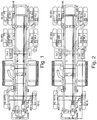
- FIG. 1 schematically illustrated a commercial vehicle having two front wheels, four middle wheels and four rear wheels, wherein the middle wheels and the rear wheels are each combined into two twin wheels.
- Some vehicle wheels are assigned ABS sensors, other vehicle wheels, however, are assigned no ABS sensors.
- ABS sensors ABS VL, ABS VR and the inner rear wheels ABS sensors ABS HL, ABS HR are assigned.
- ABS sensors ABS VL, ABS VR and the inner rear wheels ABS sensors ABS HL, ABS HR are assigned.
- the middle wheels the vehicle shown has no ABS sensors.
- the two front wheels are equipped with tire pressure monitoring units RE VL, RE VR.
- the middle wheels with tire pressure monitoring units RE MLA, RE MLI, RE MRE and RE MRA.
- the rear wheels are equipped with tire pressure monitoring units RE HLA, RE HLI, RE HRE and RE HRA.
- the tire pressure monitoring units each contain a transmitter, a pressure sensor, one or more acceleration sensors and a temperature sensor.
- the tire pressure monitoring units send data telegrams which contain a characteristic identifier of the tire pressure monitoring unit as well as pressure and temperature data and information obtained by means of the acceleration sensors.
- the commercial vehicle is equipped with two antennas Ant 1, Ant 2.
- the characteristic identifiers of the tire pressure monitoring units are assigned to the different wheel positions, ie it is determined which tire pressure monitoring unit is at which wheel position.
- the signals of the ABS sensors ABS VL, ABS VR, ABS HL, ABS HR and transmitted with the data telegrams information about the tire rotation are evaluated by a first evaluation unit AWE. Because of different tire diameter, such as as a result of different inflation pressure or different load, or because of cornering, the speeds of the different tires of a vehicle differ slightly.
- the first evaluation unit AWE 1 can therefore allocate the tire pressure monitoring units on the basis of data from the ABS sensors, for example by checking the first evaluation unit AWE 1 for which tire pressure monitoring units the rotational speeds determined on the basis of the data telegrams coincide with the rotational speeds determined from data from ABS sensors.
- the first evaluation unit AWE 1 can additionally also be used on the basis of data from an acceleration sensor the tire pressure monitoring units determine the direction of rotation of a wheel and so to distinguish tire pressure monitoring units on the left wheels of tire pressure monitoring devices on right wheels. The first evaluation unit 1 thus allocates tire pressure monitoring units to the wheels for which ABS sensors supply data.
- the wheel position is determined by evaluating the reception levels with which data telegrams of the relevant tire pressure monitoring units are received. As FIG. 1 shows, the distances of the different wheels from the antennas Ant 1, Ant 2 are each different. Since the reception levels with which data telegrams of the tire pressure monitoring units are received by the antennas Ant 1, Ant 2 decrease with increasing distance, the reception level can be determined by a statistical evaluation which wheel position is to be assigned to which characteristic identifier and thus to which tire pressure monitoring unit. Since the reception levels are affected by various disturbing influences, a statistical evaluation is required for the assignment, which is carried out by the second evaluation unit AWE 2.
- the two evaluation units AWE 1 and AWE 2 communicate with each other, for example via a data bus, such as a CAN bus.
- the first evaluation unit AWE 1 communicates its evaluation result of the second evaluation unit AWE 2.
- the second evaluation unit AWE 2 can then include this evaluation result in an ongoing evaluation, for example by now only taking into account characteristic identifiers and wheel positions for which no assignment has yet been made by the first evaluation unit AWE 1.
- the second evaluation unit AWE 2 can per se perform a complete assignment of all tire pressure monitoring units to all wheel positions or, as described above, by evaluating the reception levels with which data telegrams are received by the antennas ANT 1, ANT2, perform a complete assignment of those tire pressure monitoring units for which no assignment based on the data of the ABS sensors was possible.
- the distances between the two tires of a twin wheel differ to an antenna Ant1 or Ant2 very little, so that a distinction of the two wheel positions of a twin wheel based on the reception levels is difficult and only after receiving a relatively large number of data protocols possible.
- the second evaluation unit AWE 2 based only on the reception level assigns a tire pressure monitoring unit to a twin, but leaves open, which tire pressure monitoring unit to the inner wheel of a twin wheel and which tire pressure monitoring unit belongs to the outer wheel of a twin wheel.
- the distinction between inner and outer wheels of a twin wheel can advantageously be made on the basis of the direction of rotation.
- the acceleration sensors of the tire pressure monitoring devices of the outer wheel set the same reverse direction of rotation as the acceleration sensors of the inner wheel.
- the direction of rotation of a tire pressure monitoring device and thus the distinction of an inner twin wheel from an outer twin wheel can be made by the first or the second evaluation unit. In the illustrated embodiment, this distinction is made by the first evaluation unit AWE 1.
- the second evaluation unit then does not need to take note of the contents of the data protocols, apart from the characteristic identifier, so that the software for the second evaluation unit is very simple and consequently a simple microprocessor suffices as the second evaluation unit.
- the second evaluation unit AWE 2 therefore reports its evaluation result to the first evaluation unit AWE 1, which then completes the assignment of the tire pressure monitoring units to the wheel positions.
- the first evaluation unit AWE 1 is a separate evaluation and the second evaluation unit AWE 2 integrated into the receiver of the antenna.
- both evaluation units are integrated into receivers of the antennas, namely the first evaluation unit AWE 1 in the receiver of the first antenna ANT 1 and the second evaluation unit AWE 2 in the receiver of the second antenna ANT 2.
- any other control units of a vehicle can be used as first or second evaluation units, which are present anyway.
Landscapes
- Engineering & Computer Science (AREA)
- Mechanical Engineering (AREA)
- Physics & Mathematics (AREA)
- Electromagnetism (AREA)
- Measuring Fluid Pressure (AREA)
Abstract
Beschrieben wird ein Verfahren zum Zuordnen von an Rädern eines Fahrzeugs montierten Reifendrucküberwachungseinheiten (RE) zu Radpositionen des Fahrzeugs, wobei einigen Radpositionen des Fahrzeugs ABS-Sensoren (ABS) zugeordnet sind und anderen Radpositionen des Fahrzeugs keine ABS-Sensoren zugeordnet sind, mit den folgenden Schritten: Zuordnen von Reifendrucküberwachungseinheiten zu den Radpositionen, denen ABS-Sensoren zugeordnet sind, durch Auswertung von Signalen der ABS-Sensoren, und Zuordnen der übrigen Reifendrucküberwachungseinheiten zu den Radpositionen, denen keine ABS-Sensoren zugeordnet sind, durch Auswertung von Empfangspegeln, mit denen von den Reifendrucküberwachungseinheiten gesendete Signale empfangen werden. Erfindungsgemäß ist vorgesehen, dass die Auswertung der Signale von ABS-Sensoren von einer ersten Auswerteeinheit (AWE 1) und die Auswertung der Empfangspegel von einer zweiten Auswerteeinheit (AWE 2) durchgeführt wird. Zudem wird ein entsprechendes Reifendrucküberwachungssystem beschrieben.A method is described for assigning tire pressure monitoring units (RE) mounted on wheels of a vehicle to wheel positions of the vehicle, wherein some wheel positions of the vehicle are assigned ABS sensors (ABS) and other wheel positions of the vehicle are not assigned ABS sensors, with the following steps : Assignment of tire pressure monitoring units to the wheel positions, which are assigned to ABS sensors, by evaluating signals from the ABS sensors, and assigning the other tire pressure monitoring units to the wheel positions, which are not assigned to ABS sensors, by evaluating receive levels that of the Tire pressure monitoring units are received signals received. According to the invention, the evaluation of the signals from ABS sensors is carried out by a first evaluation unit (AWE 1) and the evaluation of the reception levels by a second evaluation unit (AWE 2). In addition, a corresponding tire pressure monitoring system is described.
Description
Die Erfindung betrifft ein Verfahren zum Zuordnen von an Rädern eines Fahrzeugs montierten Reifendrucküberwachungseinheiten zu Radpositionen des Fahrzeugs, wobei einigen Radpositionen des Fahrzeugs ABS-Sensoren zugeordnet sind und anderen Radpositionen des Fahrzeugs keine ABS-Sensoren zugeordnet sind. Ein Verfahren mit den im Oberbegriff des Anspruchs 1 angegebenen Merkmalen ist aus
Ein zu hoher oder zu niedriger Reifendruck beeinträchtigt die Fahrzeugsicherheit, führt zu erhöhtem Kraftstoffverbrauch und verstärkter Reifenabnutzung. Fahrzeuge werden deshalb mit Reifendrucküberwachungssystemen ausgerüstet, die einem Fahrer einen zu hohen oder zu tiefen Reifendruck eines Fahrzeugreifens anzeigen. Derartige Reifendrucküberwachungssysteme enthalten Reifendrucküberwachungseinheiten, die an den einzelnen Fahrzeugrädern montiert werden, einen Drucksensor enthalten, im Betrieb den Reifendruck messen und Druckdaten drahtlos an ein Empfangsgerät senden.Too high or too low tire pressure affects vehicle safety, resulting in increased fuel consumption and increased tire wear. Vehicles are therefore equipped with tire pressure monitoring systems that indicate to a driver too high or too low tire pressure of a vehicle tire. Such tire pressure monitoring systems include tire pressure monitoring units that are mounted on the individual vehicle wheels, a pressure sensor During operation, measure the tire pressure and send print data wirelessly to a receiving device.
Damit angezeigt werden kann, an welchem Rad ein zu hoher oder zu niedriger Reifendruck vorliegt, müssen die einzelnen Reifendrucküberwachungseinheiten den jeweiligen Fahrzeugrädern zugeordnet werden. Reifendrucküberwachungseinheiten übertragen deshalb ihre Druckdaten in Datentelegrammen zusammen mit einer charakteristischen Kennung, bei der sich üblicherweise um eine Ziffernfolge handelt. Diese charakteristischen Kennungen und damit die Reifendrucküberwachungseinheiten werden bei modernen Reifendrucküberwachungssystemen automatisch einer Reifenposition des Fahrzeugs zugeordnet.In order to be able to indicate on which wheel the tire pressure is too high or too low, the individual tire pressure monitoring units must be assigned to the respective vehicle wheels. Tire pressure monitoring units therefore transmit their pressure data in data telegrams together with a characteristic identifier, which is usually a sequence of numbers. These characteristic identifiers and thus the tire pressure monitoring units are automatically assigned to a tire position of the vehicle in modern tire pressure monitoring systems.
Eine Möglichkeit zur automatischen Zuordnung von Reifendrucküberwachungseinheiten zu den verschiedenen Radpositionen eines Fahrzeugs besteht darin, den Empfangspegel auszuwerten, mit dem die von den einzelnen Reifendrucküberwachungseinheiten ausgesandten Signale von einer oder mehreren am Fahrzeug angeordneten Antennen empfangen werden. Der Empfangspegel nimmt nämlich mit zunehmenden Abstand der Empfangsantenne von der sendenden Reifendrucküberwachungseinheit ab. Die Empfangspegel korrelieren deshalb mit dem Abstand der Antenne von den verschiedenen Radpositionen und ermöglichen so eine eindeutige Zuordnung.One possibility for the automatic assignment of tire pressure monitoring units to the various wheel positions of a vehicle is to evaluate the reception level with which the signals emitted by the individual tire pressure monitoring units are received by one or more antennas arranged on the vehicle. The reception level decreases with increasing distance of the receiving antenna from the transmitting tire pressure monitoring unit. The reception levels therefore correlate with the distance of the antenna from the different wheel positions and thus allow an unambiguous assignment.
Diese Zuordnung ist relativ einfach, wenn jedem Fahrzeugrad eine Antenne zugeordnet, so dass jede Antenne Signale einer bestimmten Reifendrucküberwachungseinheit mit einem sehr hohen Empfangspegel und die Signale anderer Reifendrucküberwachungseinheiten mit deutlich geringeren Empfangspegeln empfängt. Je weniger Empfangsantennen an einem Fahrzeug vorhanden sind, desto weniger deutlich sind die Unterschiede in den Empfangspegeln der Signale der verschiedenen Reifendrucküberwachungseinheiten. Hinzu kommt, dass die Empfangspegel der Signale durch verschiedene Störfaktoren, insbesondere auch die Raddrehung, beeinflusst werden. Für eine Zuordnung ist deshalb eine mehr oder weniger aufwendige statistische Auswertung erforderlich ist. In der Regel müssen deshalb eine große Zahl von Sendungen empfangen und statistisch ausgewertet werden, damit eine Zuordnung einer Reifendrucküberwachungseinheit zu einer bestimmten Radposition möglich ist.This assignment is relatively simple if an antenna is assigned to each vehicle wheel, so that each antenna receives signals from a specific tire pressure monitoring unit with a very high reception level and the signals from other tire pressure monitoring units with significantly lower reception levels. The fewer receiving antennas on a vehicle, the less clear are the differences in the reception levels of the signals of the various tire pressure monitoring units. In addition, the reception levels of the signals are influenced by various interference factors, in particular also the wheel rotation. Therefore, a more or less complicated statistical evaluation is required for an assignment. As a rule, therefore, a large number of programs must be received and evaluated statistically be, so that an assignment of a tire pressure monitoring unit to a specific wheel position is possible.
Die Zuordnung der Reifendrucküberwachungseinheiten eines Reifendrucküberwachungssystems zu bestimmten Radpositionen lässt sich bei Fahrzeugen mit ABS-Sensor vereinfachen, indem Signale der ABS-Sensoren ausgewertet werden. Entsprechende Verfahren sind beispielsweise in der
Bei Nutzfahrzeugen ist in der Regel nicht für jedes Rad ein ABS-Sensor vorhanden, sondern nur für einen Teil der Räder. Aus der
Ständiges Ziel bei der Entwicklung von Reifendrucküberwachungssystemen ist es, bei Fahrtbeginn möglichst schnell eine Zuordnung der Reifendrucküberwachungseinheiten zu den einzelnen Radpositionen des Fahrzeugs zu erzielen und dabei den Hardwareaufwand, insbesondere die Anzahl der Empfangsantennen, möglichst gering zu halten.A constant goal in the development of tire pressure monitoring systems is to achieve the fastest possible assignment of the tire pressure monitoring units to the individual wheel positions of the vehicle at the start of the journey while keeping the hardware costs, in particular the number of receiving antennas, as low as possible.
Aufgabe der vorliegenden Erfindung ist es, einen Weg aufzuzeigen, wie dieses Ziel bei einem Fahrzeug, das nur für einen Teil seiner Räder ABS-Sensoren hat, noch besser erreicht werden kann.Object of the present invention is to show a way how this goal can be achieved even better in a vehicle that has ABS sensors only for a part of its wheels.
Diese Aufgabe wird durch ein Verfahren mit den im Anspruch 1 angegebenen Merkmalen sowie durch ein Reifendrucküberwachungssystem gemäß Anspruch 9 gelöst. Vorteilhafte Weiterbildungen der Erfindung sind Gegenstand von Unteransprüchen.This object is achieved by a method having the features specified in
Ein erfindungsgemäßes Reifendrucküberwachungssystem hat mehrere Auswerteeinheiten, nämlich eine Auswerteeinheit, welche die Signale von ABS-Sensoren auswertet, um Reifendrucküberwachungseinheiten jenen Rädern zuzuordnen, für die Daten von ABS-Sensoren vorliegen, und eine zweite Auswerteeinheit, welche zur Zuordnung der übrigen Reifendrucküberwachungseinheiten zu den Rädern, für die keine Daten von ABS-Sensoren vorliegen, die Empfangspegel auswertet, mit denen Sendungen der Reifendrucküberwachungseinheiten empfangen werden. Anstatt in einer einzigen Auswerteeinheit sowohl Daten von ABS-Sensoren also auch Empfangspegel auszuwerten, werden erfindungsgemäß also Daten von ABS-Sensoren in einer ersten Auswerteeinheit und Empfangspegel in einer zweiten Auswerteeinheit ausgewertet, die in einem Abstand von der ersten Auswerteeinheit angeordnet ist.A tire pressure monitoring system according to the invention has a plurality of evaluation units, namely an evaluation unit which evaluates the signals from ABS sensors in order to assign tire pressure monitoring units to those wheels for which data from ABS sensors are present, and a second evaluation unit which is used to associate the remaining tire pressure monitoring units with the wheels. for which there are no data from ABS sensors that evaluates reception levels with which transmissions of the tire pressure monitoring units are received. Instead of evaluating both data from ABS sensors and reception levels in a single evaluation unit, according to the invention data from ABS sensors in a first evaluation unit and reception levels are evaluated in a second evaluation unit, which is arranged at a distance from the first evaluation unit.
Obwohl erfindungsgemäß eine zweite Auswerteeinheit benötigt wird, lässt sich so der Hardwareaufwand des Reifendrucküberwachungssystems deutlich reduzieren. Indem nämlich die Auswertung der ABS-Signale von der Auswertung der Empfangspegel getrennt wird, werden statt eines komplexen Auswerteprogramms nun zwei einfachere Auswerteprogramme benötigt. Dementsprechend werden erfindungsgemäß zwei einfachere, weniger leistungsfähige Auswerteeinheiten, etwa zwei Mikroprozessoren mit kleinerem Speicher, statt einer leistungsfähigeren Auswerteeinheit benötigt.Although a second evaluation unit is required according to the invention, the hardware complexity of the tire pressure monitoring system can be significantly reduced. By separating the evaluation of the ABS signals from the evaluation of the reception levels, instead of a complex evaluation program, two simpler evaluation programs are now required. Accordingly, according to the invention, two simpler, less powerful evaluation units, for example two microprocessors with a smaller memory, are needed instead of a more powerful evaluation unit.
Anstatt in einem Fahrzeug zwei Auswerteeinheiten exklusiv für das Reifendrucküberwachungssystem vorzusehen, kann die Auswertung der Empfangspegel oder auch die Auswertung der ABS-Signale von einer Auswerteeinheit des Fahrzeugs übernommen werden, die im Fahrzeug auch andere Aufgaben übernimmt und auch für andere Systeme zur Verfügung steht. Beispielsweise kann die Auswertung der Empfangspegel von einem Mikroprozessor vorgenommen werden, der in einem Empfänger ohnehin enthalten ist.Instead of providing two evaluation units exclusively for the tire pressure monitoring system in a vehicle, the evaluation of the reception levels or also the evaluation of the ABS signals can be carried out by an evaluation unit of the vehicle, which also assumes other tasks in the vehicle and is also available for other systems. For example, the evaluation of the reception levels can be performed by a microprocessor, which is included in a receiver anyway.
Eine vorteilhafte Weiterbildung der Erfindung sieht vor, dass die erste Auswerteeinheit und die zweite Auswerteeinheit über ein Bussystem des Fahrzeugs miteinander kommunizieren.An advantageous development of the invention provides that the first evaluation unit and the second evaluation unit communicate with each other via a bus system of the vehicle.
Eine Zuordnung von Reifendrucküberwachungseinheiten zu einzelnen Radpositionen mittels Daten von ABS-Sensoren kann beispielsweise mit dem in der
Um die Drehfrequenz zu ermitteln, können die Reifendrucküberwachungseinrichtungen mit einem oder mehreren Beschleunigungssensoren versehen sein, beispielsweise mit Sensoren zur Messung der Zentrifugalbeschleunigung oder Bahnbeschleunigung.In order to determine the rotational frequency, the tire pressure monitoring devices may be provided with one or more acceleration sensors, for example with sensors for measuring the centrifugal acceleration or web acceleration.
Eine Zuordnung von Reifendrucküberwachungseinheiten zu einzelnen Radpositionen mittels der Empfangspegel, mit denen von den Reifendrucküberwachungseinheiten ausgesandte Datentelegramme empfangen werden, beruht auf der Annahme, dass der Empfangspegel bzw. die Empfangsfeldstärke im statistischen Mittel umso größer ist, je näher die Reifendrucküberwachungseinheit an der Empfangsantenne ist. Für diese Zuordnung genügt an sich eine einzige Antenne, mit der die Datentelegramme empfangen werden. Die Zuordnung lässt sich aber umso schneller durchführen, je mehr Antennen vorhanden sind.An assignment of tire pressure monitoring units to individual wheel positions by means of the reception levels with which data telegrams transmitted by the tire pressure monitoring units are received is based on the assumption that the closer the tire pressure monitoring unit is to the receiving antenna, the greater the reception level or the reception field strength in the statistical average. For this assignment a single antenna with which the data telegrams are received is sufficient. However, the assignment can be made faster, the more antennas are available.
Beispielsweise kann die zweite Auswerteeinheit für jede Antenne und für jede charakteristische Kennung, d.h. für jede Reifendrucküberwachungseinheit, erfassen, wie groß der Empfangspegel an der betreffenden Antenne ist. Die zweite Auswerteeinheit kann dabei auch laufend einen Durchschnittswert ermitteln, mit dem Signale der betreffenden Reifendrucküberwachungseinheit von der betreffenden Antenne empfangen werden. Die zweite Auswerteeinheit kann dann zur Zuordnung beispielsweise diese Durchschnittswerte der Größe nach ordnen. Sobald diese Durchschnittswerte hinreichend stabil sind, sich also die Reihenfolge der Durchschnittswerte in einer vorgegebenen Zeitspanne oder beim Hinzukommen einer vorgegeben Anzahl neuer Empfangspegelwerte nicht mehr ändert, kann auf der Grundlage der Reihenfolge der Durchschnittswerte nach der Größe eine Zuordnung der Reifendrucküberwachungseinheiten zu den Radpositionen erfolgen. Dazu wird die charakteristische Kennung, die im Durchschnitt mit dem größten Empfangspegel empfangen wird, der Radposition zugeordnet, die dieser Antenne am nächsten ist, die charakteristische Kennung, die im Durchschnitt mit dem zweitgrößten Empfangspegel empfangen wird, der Radposition zugeordnet, die dieser Antenne am zweitnächsten ist, und so weiter.For example, the second evaluation unit for each antenna and for each characteristic identifier, ie for each tire pressure monitoring unit, can detect how large the reception level is at the relevant antenna. The second evaluation unit can also continuously determine an average value with which signals of the relevant tire pressure monitoring unit are received by the relevant antenna. The second evaluation unit can then be assigned For example, sort these averages by size. As soon as these average values are sufficiently stable, ie if the order of the average values no longer changes in a given period of time or if a predefined number of new reception level values are added, the tire pressure monitoring units can be assigned to the wheel positions on the basis of the order of the average values according to the size. For this purpose, the characteristic identifier received on the average with the largest reception level is assigned to the wheel position closest to this antenna, the characteristic identifier received on average at the second largest reception level is assigned to the wheel position, and that antenna the second closest is, and so on.
Bei einem erfindungsgemäßen Reifendrucküberwachungssystem können die beiden Auswerteeinheiten unabhängig voneinander arbeiten, insbesondere ist es prinzipiell möglich, dass die zweite Auswerteeinheit durch Auswertung der Empfangspegel für alle Räder des Fahrzeugs eine Zuordnung der Reifendrucküberwachungseinheiten vornimmt. Die Zuordnung lässt sich im Regelfall aber beschleunigen, indem die erste Auswerteeinheit ihr Auswertungsergebnis der zweiten Auswerteeinheit mitteilt, sobald dieses vorliegt. Die zweite Auswerteeinheit kann dann das erste Auswertungsergebnis in die bereits begonnene statistische Auswertung einbeziehen. Beispielsweise indem dann nur noch die übrigen Radpositionen, denen durch das Auswertungsergebnis der ersten Auswerteeinheit noch keine Reifendrucküberwachungseinheiten zugeordnet wurden, einer Reifendrucküberwachungseinheit zugeordnet werden.In a tire pressure monitoring system according to the invention, the two evaluation units can operate independently of one another, in particular it is possible in principle for the second evaluation unit to carry out an assignment of the tire pressure monitoring units by evaluating the reception levels for all wheels of the vehicle. As a rule, however, the assignment can be accelerated by the first evaluation unit notifying its evaluation result to the second evaluation unit as soon as it is present. The second evaluation unit can then include the first evaluation result in the already started statistical evaluation. For example, in that then only the remaining wheel positions, which have not yet been assigned any tire pressure monitoring units by the evaluation result of the first evaluation unit, are assigned to a tire pressure monitoring unit.
Indem die erste Auswerteeinheit und die zweite Auswerteeinheit unabhängig voneinander mit der Zuordnung beginnen, lässt sich in vielen Fällen die Zuordnung verkürzen. Beispielsweise kann die Zeitdauer, die von der ersten Auswerteeinheit benötigt wird, um Reifendrucküberwachungseinheiten jenen Rädern zuzuordnen, denen ABS Sensoren zugeordnet sind, von den konkreten Fahrtbedingungen abhängen, insbesondere davon, ob eine kurvenreiche Strecke gefahren wird oder nicht. In dieser Zeit kann die zweite Auswerteeinheit bereits Daten für eine statistische Auswertung der Zuordnung auf der Grundlage der Empfangspegel sammeln und diese auswerten.Since the first evaluation unit and the second evaluation unit start the assignment independently of one another, in many cases the assignment can be shortened. For example, the time required by the first evaluation unit to assign tire pressure monitoring units to those wheels to which ABS sensors are assigned may depend on the actual driving conditions, in particular whether a winding route is driven or not. During this time, the second evaluation unit can already collect data for a statistical evaluation of the assignment on the basis of the reception levels and evaluate them.
Nutzfahrzeuge haben oft Zwillingsräder. Bei Zwillingsrädern kann eine Zuordnung einer Reifendrucküberwachungseinheit zu dem inneren Rad oder äußeren Rad des Zwillings auf der Grundlage der Empfangspegel schwierig sein, da die Abstände zwischen den beiden Zwillingsrädern nur klein sind. Eine vorteilhafte Weiterbildung der vorliegenden Erfindung sieht deshalb vor, dass die zweite Auswerteeinheit auf der Grundlage der Empfangspegel Reifendrucküberwachungseinheiten zunächst nur dem Zwillingsrad zuordnet, aber noch keine Entscheidung trifft, welche der beiden Reifendrucküberwachungseinheiten dem inneren bzw. dem äußeren Rad eines Zwillingsrades zuzuordnen ist. Diese Entscheidung kann vorteilhaft in einem zweiten Schritt anhand der Drehrichtung vorgenommen werden. Innere und äußere Räder eines Zwillingsrades sind nämlich entgegengesetzt orientiert. Wenn die Reifendrucküberwachungseinheiten stets mit gleicher Orientierung an einem Rad montiert sind, detektieren die Beschleunigungssensoren der Reifendrucküberwachungseinheiten eines Zwillingsrades deshalb verschiedene Drehrichtungen, z.B. eine Linksdrehung des inneren Rades und eine Rechtsdrehung des äußeren Rades oder umgekehrt.Commercial vehicles often have twin wheels. In twin wheels, it may be difficult to associate a tire pressure monitoring unit with the twin's inner wheel or outer wheel based on the reception levels because the distances between the two twin wheels are small. An advantageous development of the present invention therefore provides that the second evaluation unit first assigns tire pressure monitoring units only to the twin wheel on the basis of the reception level, but still does not make a decision as to which of the two tire pressure monitoring units is to be assigned to the inner or the outer wheel of a twin wheel. This decision can advantageously be made in a second step based on the direction of rotation. Inner and outer wheels of a twin wheel are in fact oriented opposite. Therefore, when the tire pressure monitoring units are always mounted on a wheel with the same orientation, the acceleration sensors of the tire pressure monitoring units of a twin wheel detect different directions of rotation, e.g. a left turn of the inner wheel and a right turn of the outer wheel or vice versa.
Entsprechende Daten eines Beschleunigungssensors, welche die Drehrichtung angeben oder aus denen sich die Drehrichtung ermitteln lässt, können zur Unterscheidung von inneren und äußeren Rädern eines Zwillingsrades verwendet werden. Diese Entscheidung kann ebenfalls von der zweiten Auswerteeinheit vorgenommen werden. Eine vorteilhafte Weiterbildung der Erfindung sieht jedoch vor, dass die Unterscheidung zwischen inneren und äußeren Rädern eines Zwillingsrades und somit auch die Zuordnung einer Reifendrucküberwachungseinheit zu einem inneren bzw. äußeren Rad eines Zwillingsrades von der ersten Auswerteeinheit vorgenommen werden. Für die Auswertung der Empfangspegel braucht die zweite Auswerteeinheit nämlich Inhalt der Datentelegramme abgesehen von der charakteristischen Kennung nicht berücksichtigen. Die Programme der Auswerteeinheiten lassen sich deshalb vereinfachen, indem die zweite Auswerteeinheit eine Reifendrucküberwachungseinheit nur einem Zwillingsrad zuordnet und offenlässt, ob die Reifendrucküberwachungseinheit dem inneren oder dem äußeren Rad des Zwillingsrads zuzuordnen ist. Diese Unterscheidung wird dann von der ersten Auswerteeinheit anhand der in den Datentelegrammen enthaltenen Daten der Beschleunigungssensoren der Reifendrucküberwachungseinheit vorgenommen. Die erste Auswerteeinheit muss nämlich ohnehin den Inhalt der Datentelegramme auswerten, um eine Zuordnung auf der Grundlage der Daten von ABS-Sensoren vornehmen zu können, etwa die Drehzahl eines Rades aus Beschleunigungsdaten eines Sensors einer Reifendrucküberwachungseinheit zu ermitteln.Corresponding data of an acceleration sensor, which indicate the direction of rotation or from which the direction of rotation can be determined, can be used to distinguish between inner and outer wheels of a twin wheel. This decision can also be made by the second evaluation unit. An advantageous development of the invention provides, however, that the distinction between inner and outer wheels of a twin wheel and thus the assignment of a tire pressure monitoring unit to an inner or outer wheel of a twin wheel are made by the first evaluation unit. For the evaluation of the reception levels, the second evaluation unit need not take into account content of the data telegrams apart from the characteristic identifier. The programs of the evaluation units can therefore be simplified in that the second evaluation unit assigns a tire pressure monitoring unit to only one twin wheel and leaves open whether the tire pressure monitoring unit is to be assigned to the inner or the outer wheel of the twin wheel. This distinction is then made by the first evaluation unit on the basis of the data contained in the data telegrams data of the acceleration sensors the tire pressure monitoring unit made. The first evaluation unit must in any case evaluate the content of the data telegrams in order to be able to make an assignment on the basis of the data from ABS sensors, for example to determine the rotational speed of a wheel from acceleration data of a sensor of a tire pressure monitoring unit.
Eine weitere vorteilhafte Weiterbildung der Erfindung sieht vor, dass die zweite Auswerteeinheit ihr Auswertungsergebnis der ersten Auswerteeinheit mitteilt und die erste Auswerteeinheit dann eine Unterscheidung zwischen inneren und äußeren Zwillingsrädern vornimmt.A further advantageous development of the invention provides that the second evaluation unit notifies its evaluation result of the first evaluation unit and the first evaluation unit then makes a distinction between inner and outer twin wheels.
Da die erste Auswerteeinheit den Inhalt der von den Reifendrucküberwachungseinheiten gesendeten Datentelegramme lesen und auswerten muss, um ihre Zuordnung auf der Grundlage der Daten von ABS-Sensoren vornehmen zu können, ist es vorteilhaft, wenn die erste Auswerteeinheit auch die in den Datentelegrammen enthaltenen Druckdaten auswertet, also die eigentliche Drucküberwachung vornimmt. Bei einem Ausführungsbeispiel der Erfindung kann also die erste Auswerteeinheit einen zu niedrigen oder zu hohen Reifendruck oder eine rasche Druckänderung erkennen und veranlassen, dass dies einem Fahrer des Fahrzeugs angezeigt wird.Since the first evaluation unit must read and evaluate the content of the data telegrams sent by the tire pressure monitoring units in order to be able to make their assignment on the basis of the data from ABS sensors, it is advantageous if the first evaluation unit also evaluates the print data contained in the data telegrams, So does the actual pressure monitoring. In one exemplary embodiment of the invention, therefore, the first evaluation unit can detect a tire pressure that is too low or too high or a rapid pressure change and cause it to be displayed to a driver of the vehicle.
Weitere Einzelheiten und Vorteile der Erfindung werden an Ausführungsbeispielen unter Bezugnahme auf die beigefügten Figuren erläutert. Gleiche und einander entsprechende Komponenten sind in den Figuren mit übereinstimmenden Bezugszeichen gekennzeichnet. Es zeigen:
- Fig. 1
- eine schematische Darstellung eines Nutzfahrzeugs mit einem Ausführungsbeispiel eines erfindungsgemäßen Reifendrucküberwachungssystems; und
- Fig. 2
- eine schematische Darstellung eines Nutzfahrzeugs mit einem weiteren Ausführungsbeispiel eines erfindungsgemäßen Reifendrucküberwachungssystems.
- Fig. 1
- a schematic representation of a commercial vehicle with an embodiment of a tire pressure monitoring system according to the invention; and
- Fig. 2
- a schematic representation of a commercial vehicle with a further embodiment of a tire pressure monitoring system according to the invention.
In
Die beiden Vorderräder sind mit Reifendrucküberwachungseinheiten RE VL, RE VR ausgerüstet. Die mittleren Räder mit Reifendrucküberwachungseinheiten RE MLA, RE MLI, RE MRE und RE MRA. Die hinteren Räder sind mit Reifendrucküberwachungseinheiten RE HLA, RE HLI, RE HRE und RE HRA ausgerüstet. Die Reifendrucküberwachungseinheiten enthalten jeweils einen Sender, einen Drucksensor, einen oder mehrere Beschleunigungssensoren sowie einen Temperatursensor. Im Betrieb senden die Reifendrucküberwachungseinheiten Datentelegramme, die eine charakteristische Kennung der Reifendrucküberwachungseinheit sowie Druck- und Temperaturdaten und mittels der Beschleunigungssensoren gewonnene Informationen enthalten. Zum Empfang dieser Datentelegramme ist das Nutzfahrzeug mit zwei Antennen Ant 1, Ant 2 ausgerüstet.The two front wheels are equipped with tire pressure monitoring units RE VL, RE VR. The middle wheels with tire pressure monitoring units RE MLA, RE MLI, RE MRE and RE MRA. The rear wheels are equipped with tire pressure monitoring units RE HLA, RE HLI, RE HRE and RE HRA. The tire pressure monitoring units each contain a transmitter, a pressure sensor, one or more acceleration sensors and a temperature sensor. During operation, the tire pressure monitoring units send data telegrams which contain a characteristic identifier of the tire pressure monitoring unit as well as pressure and temperature data and information obtained by means of the acceleration sensors. To receive these data telegrams, the commercial vehicle is equipped with two
Bei jedem Fahrtbeginn werden die charakteristischen Kennungen der Reifendrucküberwachungseinheiten den verschieden Radpositionen zugeordnet, d.h. es wird ermittelt, welche Reifendrucküberwachungseinheit sich an welcher Radposition befindet. Dazu werden von einer ersten Auswerteeinheit AWE 1 die Signale der ABS-Sensoren ABS VL, ABS VR, ABS HL, ABS HR sowie mit den Datentelegrammen übermittelten Informationen über die Reifendrehung ausgewertet. Wegen unterschiedlichem Reifendurchmesser, etwa als Folge von unterschiedlichem Fülldruck oder unterschiedlicher Last, oder wegen Kurvenfahrt unterscheiden sich die Drehzahlen der verschiedenen Reifen eines Fahrzeugs geringfügig. Die erste Auswerteeinheit AWE 1 kann deshalb die Reifendrucküberwachungseinheiten anhand von Daten der ABS-Sensoren zuordnen, etwa indem die erste Auswerteeinheit AWE 1 überprüft, für welche Reifendrucküberwachungseinheiten die anhand der Datentelegramme ermittelten Drehzahlen mit den aus Daten von ABS-Sensoren ermittelten Drehzahlen übereinstimmen. Im Rahmen dieser Zuordnung kann die erste Auswerteeinheit AWE 1 zusätzlich auch anhand von Daten eines Beschleunigungssensors der Reifendrucküberwachungseinheiten die Drehrichtung eines Rades ermitteln und so Reifendrucküberwachungseinheiten an linken Rädern von Reifendrucküberwachungseinrichtungen an rechten Rädern zu unterscheiden. Die erste Auswerteeinheit 1 ordnet somit den Rädern, für die ABS-Sensoren Daten liefern, Reifendrucküberwachungseinheiten zu.At each start of the journey, the characteristic identifiers of the tire pressure monitoring units are assigned to the different wheel positions, ie it is determined which tire pressure monitoring unit is at which wheel position. For this purpose, the signals of the ABS sensors ABS VL, ABS VR, ABS HL, ABS HR and transmitted with the data telegrams information about the tire rotation are evaluated by a first evaluation unit AWE. Because of different tire diameter, such as as a result of different inflation pressure or different load, or because of cornering, the speeds of the different tires of a vehicle differ slightly. The first
Für die übrigen Reifendrucküberwachungseinheiten wird die Radposition durch Auswertung der Empfangspegel ermittelt, mit denen Datentelegramme der betreffenden Reifendrucküberwachungseinheiten empfangen werden. Wie
Die beiden Auswerteeinheiten AWE 1 und AWE 2 kommunizieren miteinander, beispielsweise über einen Datenbus, etwa einen CAN Bus. Die erste Auswerteeinheit AWE 1 teilt ihr Auswertungsergebnis der zweiten Auswerteeinheit AWE 2 mit. Die zweite Auswerteeinheit AWE 2 kann dann dieses Auswerteergebnis in eine laufende Auswertung einbeziehen, beispielsweise indem nun nur noch charakteristische Kennungen und Radpositionen berücksichtigt werden, für die von der ersten Auswerteeinheit AWE 1 noch keine Zuordnung vorgenommen wurde.The two
Die zweite Auswerteeinheit AWE 2 kann an sich eine vollständige Zuordnung aller Reifendrucküberwachungseinheiten zu allen Radpositionen vornehmen, bzw. wie vorstehend beschrieben durch Auswertung der Empfangspegel, mit denen Datentelegramme von den Antennen ANT 1, ANT2 empfangen werden, eine vollständige Zuordnung jener Reifendrucküberwachungseinheiten vornehmen, für die keine Zuordnung anhand der Daten der ABS-Sensoren möglich war. Allerdings unterscheiden sich die Abstände der beiden Reifen eines Zwillingsrades zu einer Antenne Ant1 oder Ant2 nur sehr wenig, so dass eine Unterscheidung der beiden Radpositionen eines Zwillingsrades auf der Grundlage der Empfangspegel schwierig ist und erst nach Empfang einer relativ großen Anzahl von Datenprotokollen möglich. Um die für eine Zuordnung benötigte Zeit abzukürzen, kann es vorteilhaft sein, wenn die zweite Auswerteeinheit AWE 2 auf der Grundlage der Empfangspegel nur eine Zuordnung einer Reifendrucküberwachungseinheit zu einem Zwillingrad vornimmt, aber offen lässt, welche Reifendrucküberwachungseinheit zu dem inneren Rad eines Zwillingsrads und welche Reifendrucküberwachungseinheit zu dem äußeren Rad eines Zwillingsrads gehört.The second
Die Unterscheidung zwischen inneren und äußeren Rädern eines Zwillingsrades kann vorteilhaft anhand der Drehrichtung vorgenommen. Bei gleicher Positionierung der Reifendrucküberwachungseinrichtung relativ zu dem Rad, an dem sie montiert ist, stellen die Beschleunigungssensoren der Reifendrucküberwachungseinrichten des äußeren Rades nämliche die umgekehrte Drehrichtung fest, wie die Beschleunigungssensoren des inneren Rades. Indem mit den Datentelegrammen auch Daten aus Messungen der Beschleunigungssensoren übermittelt werden, lässt sich so die Zuordnung beschleunigen. Die Drehrichtung einer Reifendrucküberwachungseinrichtung und somit die Unterscheidung eines inneren Zwillingsrades von einem äußeren Zwillingsrad kann von der ersten oder der zweiten Auswerteeinheit vorgenommen werden. Bei dem dargestellten Ausführungsbeispiel wird diese Unterscheidung von der ersten Auswerteeinheit AWE 1 vorgenommen. Vorteilhaft muss die zweite Auswerteeinheit den Inhalt der Datenprotokolle dann, abgesehen von der charakteristischen Kennung, nicht zur Kenntnis nehmen, so dass sich die Software für die zweite Auswerteeinheit sehr einfach halten und folglich ein einfacher Mikroprozessor als zweite Auswerteeinheit genügt. Die zweite Auswerteeinheit AWE 2 meldet ihr Auswertungsergebnis deshalb an die erste Auswertungseinheit AWE 1, die dann die Zuordnung der Reifendrucküberwachungseinheiten zu den Radpositionen vervollständigt.The distinction between inner and outer wheels of a twin wheel can advantageously be made on the basis of the direction of rotation. With the same positioning of the tire pressure monitoring device relative to the wheel on which it is mounted, the acceleration sensors of the tire pressure monitoring devices of the outer wheel set the same reverse direction of rotation as the acceleration sensors of the inner wheel. By also transferring data from measurements of the acceleration sensors with the data telegrams, the assignment can be accelerated. The direction of rotation of a tire pressure monitoring device and thus the distinction of an inner twin wheel from an outer twin wheel can be made by the first or the second evaluation unit. In the illustrated embodiment, this distinction is made by the first
Bei dem in
Claims (10)
die Auswertung der Signale von ABS-Sensoren von einer ersten Auswerteeinheit (AWE 1) und die Auswertung der Empfangspegel von einer zweiten Auswerteeinheit (AWE 2) durchgeführt wird.Method for assigning tire pressure monitoring units (RE) mounted on wheels of a vehicle to wheel positions of the vehicle, wherein some wheel positions of the vehicle are assigned ABS sensors (ABS) and other wheel positions of the vehicle are not assigned ABS sensors, with the following steps:
the evaluation of the signals from ABS sensors is carried out by a first evaluation unit (AWE 1) and the evaluation of the reception levels by a second evaluation unit (AWE 2).
mehreren Reifendrucküberwachungseinheiten, die einen Drucksensor und einen Beschleunigungssensor enthalten und im Betrieb Datentelegramme aussenden, die einen charakteristische Kennung sowie Druckdaten enthalten, einem Empfänger zum Empfangen der Datentelegramme,
einer ersten Auswerteeinheit, die dafür eingerichtet ist, zur Zuordnung der charakteristischen Kennungen zu Radpositionen Signale von ABS-Sensoren auszuwerten, und
einer zweiten Auswerteeinheit, die dafür eingerichtet ist, zur Zuordnung der charakteristischen Kennungen zu Radpositionen Empfangspegel auszuwerten, mit denen der Empfänger Datentelegramme der Reifendrucküberwachungseinheiten empfängt.Tire pressure monitoring system with
a plurality of tire pressure monitoring units, which contain a pressure sensor and an acceleration sensor and emit data telegrams in operation, which contain a characteristic identifier and pressure data, a receiver for receiving the data telegrams,
a first evaluation unit which is set up to evaluate signals from ABS sensors for the assignment of the characteristic identifiers to wheel positions, and
a second evaluation unit, which is adapted to evaluate the assignment of the characteristic identifiers to wheel positions reception levels, with which the receiver receives data telegrams of the tire pressure monitoring units.
Applications Claiming Priority (1)
| Application Number | Priority Date | Filing Date | Title |
|---|---|---|---|
| DE102018104673.1A DE102018104673A1 (en) | 2018-03-01 | 2018-03-01 | Method for assigning tire pressure monitoring units to wheel positions of the vehicle and tire pressure monitoring system |
Publications (2)
| Publication Number | Publication Date |
|---|---|
| EP3533641A1 true EP3533641A1 (en) | 2019-09-04 |
| EP3533641B1 EP3533641B1 (en) | 2022-03-30 |
Family
ID=65408963
Family Applications (1)
| Application Number | Title | Priority Date | Filing Date |
|---|---|---|---|
| EP19156454.1A Active EP3533641B1 (en) | 2018-03-01 | 2019-02-11 | Method for locating position of wheels in motor vehicle in a tire pressure monitoring system, and device |
Country Status (2)
| Country | Link |
|---|---|
| EP (1) | EP3533641B1 (en) |
| DE (1) | DE102018104673A1 (en) |
Cited By (2)
| Publication number | Priority date | Publication date | Assignee | Title |
|---|---|---|---|---|
| EP3865318A1 (en) * | 2020-02-17 | 2021-08-18 | Continental Reifen Deutschland GmbH | Operation of a control system for a motor vehicle |
| CN115135517A (en) * | 2020-02-18 | 2022-09-30 | 大陆汽车科技有限公司 | Method for identifying an electronic wheel unit on a vehicle wheel and use thereof |
Citations (6)
| Publication number | Priority date | Publication date | Assignee | Title |
|---|---|---|---|---|
| DE69322394T2 (en) * | 1992-09-16 | 1999-08-26 | Sumitomo Electric Industries | DEVICE AND METHOD FOR DETECTING PRESSURE DROP IN THE TIRE |
| EP0806306B1 (en) | 1996-05-09 | 2003-08-06 | Continental Aktiengesellschaft | Tyre pressure monitoring system of an automobile and method of allocating it to a tire position |
| DE19734323B4 (en) | 1997-08-08 | 2004-05-06 | Continental Aktiengesellschaft | Method for carrying out the assignment of the wheel position to tire pressure control devices in a tire pressure control system of a motor vehicle |
| FR2921588A1 (en) * | 2007-09-28 | 2009-04-03 | Continental Automotive Gmbh | DEVICE AND METHODS FOR DISTINGUISHING TIRES OF A TIMBER WHEEL SYSTEM |
| DE102013220873A1 (en) * | 2013-10-15 | 2015-04-16 | Continental Automotive Gmbh | Method and arrangement for locating the installation position of wheels in a motor vehicle |
| DE102010037512B4 (en) | 2010-08-31 | 2015-09-24 | Huf Hülsbeck & Fürst Gmbh & Co. Kg | A method for assigning identifiers of wheel electronics of a tire pressure monitoring system of a vehicle to the positions of ABS sensors on the vehicle |
-
2018
- 2018-03-01 DE DE102018104673.1A patent/DE102018104673A1/en active Pending
-
2019
- 2019-02-11 EP EP19156454.1A patent/EP3533641B1/en active Active
Patent Citations (7)
| Publication number | Priority date | Publication date | Assignee | Title |
|---|---|---|---|---|
| DE69322394T2 (en) * | 1992-09-16 | 1999-08-26 | Sumitomo Electric Industries | DEVICE AND METHOD FOR DETECTING PRESSURE DROP IN THE TIRE |
| EP0806306B1 (en) | 1996-05-09 | 2003-08-06 | Continental Aktiengesellschaft | Tyre pressure monitoring system of an automobile and method of allocating it to a tire position |
| DE19734323B4 (en) | 1997-08-08 | 2004-05-06 | Continental Aktiengesellschaft | Method for carrying out the assignment of the wheel position to tire pressure control devices in a tire pressure control system of a motor vehicle |
| FR2921588A1 (en) * | 2007-09-28 | 2009-04-03 | Continental Automotive Gmbh | DEVICE AND METHODS FOR DISTINGUISHING TIRES OF A TIMBER WHEEL SYSTEM |
| DE102010037512B4 (en) | 2010-08-31 | 2015-09-24 | Huf Hülsbeck & Fürst Gmbh & Co. Kg | A method for assigning identifiers of wheel electronics of a tire pressure monitoring system of a vehicle to the positions of ABS sensors on the vehicle |
| DE102013220873A1 (en) * | 2013-10-15 | 2015-04-16 | Continental Automotive Gmbh | Method and arrangement for locating the installation position of wheels in a motor vehicle |
| WO2015055424A1 (en) | 2013-10-15 | 2015-04-23 | Continental Automotive Gmbh | Method and arrangement for locating the installation position of wheels in a motor vehicle |
Cited By (2)
| Publication number | Priority date | Publication date | Assignee | Title |
|---|---|---|---|---|
| EP3865318A1 (en) * | 2020-02-17 | 2021-08-18 | Continental Reifen Deutschland GmbH | Operation of a control system for a motor vehicle |
| CN115135517A (en) * | 2020-02-18 | 2022-09-30 | 大陆汽车科技有限公司 | Method for identifying an electronic wheel unit on a vehicle wheel and use thereof |
Also Published As
| Publication number | Publication date |
|---|---|
| EP3533641B1 (en) | 2022-03-30 |
| DE102018104673A1 (en) | 2019-09-05 |
Similar Documents
| Publication | Publication Date | Title |
|---|---|---|
| EP0806306B1 (en) | Tyre pressure monitoring system of an automobile and method of allocating it to a tire position | |
| DE102011050636B4 (en) | A method for assigning identifiers of wheel electronics of a tire pressure monitoring system of a vehicle to the positions of the wheels on the vehicle | |
| DE102012109307B4 (en) | Wheel module for detecting wheel rotation using a one-dimensional acceleration sensor | |
| EP1621366A1 (en) | Method and device for the allocation of triggered transmitters of a tyre monitoring system | |
| EP2516182A1 (en) | Method and device for locating the installation position of vehicle wheels in a motor vehicle | |
| DE10144360A1 (en) | Method for assigning tire pressure measuring devices of a motor vehicle to wheel positions and device for measuring tire pressure | |
| DE102005022287A1 (en) | The tire pressure detecting apparatus having a function of detecting the tire location | |
| DE112016000502T5 (en) | Tire wheel position detecting device and tire pressure control system with the tire wheel position detecting device | |
| DE102009009627A1 (en) | Automatic location of wireless tire pressure monitoring sensors | |
| DE10223214A1 (en) | Method for assigning tire modules to wheel positions of a tire pressure monitoring system for a motor vehicle and device for monitoring the tire pressure | |
| DE10152338B4 (en) | Method and system for monitoring the wheels of a motor vehicle | |
| EP3533641B1 (en) | Method for locating position of wheels in motor vehicle in a tire pressure monitoring system, and device | |
| DE102010000919A1 (en) | Method for tire air pressure measurement and evaluation with an assignment of wheel positions and tire pressure measuring system | |
| DE102008045867A1 (en) | System for monitoring tire pressure in vehicles | |
| DE10306498A1 (en) | Automatic vehicle tire monitor, to determine the wear on the running tread profile, has sensors at the wheels linked to an evaluation unit which is also connected to a satellite position signal receiver | |
| EP3317130B1 (en) | Method for allocating tyre pressure control units to wheel positions of a vehicle | |
| EP1528988B1 (en) | Method for assigning wheels of a motor vehicle to the respective vehicle axle | |
| DE102004024388B4 (en) | Vehicle wheel`s position determining device, has evaluation device for determining position of wheel based on disturbing components of acceleration signal that is caused by unevenness of road surface | |
| EP1663674B1 (en) | Allocation method for a combined tyre pressure monitoring system in motor vehicles | |
| EP3643541B1 (en) | Tyre pressure monitoring system | |
| WO2021197891A1 (en) | Method for monitoring the tyre pressure of a vehicle wheel, and tyre pressure monitoring unit | |
| DE102010042198A1 (en) | Method for operating motor vehicle, involves transmitting predetermined number of message signals according to current angular position of wheels to determine target position of wheels | |
| DE102015212945A1 (en) | Method and device for locating the installation positions of electronic wheel units arranged on vehicle wheels of a vehicle | |
| DE102016217684B4 (en) | Method for recognizing radio signals that are sent from electronic wheel units to the wheels of a vehicle, and receiving device for such radio signals | |
| EP3523143B1 (en) | Method for operating a tyre pressure monitoring system |
Legal Events
| Date | Code | Title | Description |
|---|---|---|---|
| PUAI | Public reference made under article 153(3) epc to a published international application that has entered the european phase |
Free format text: ORIGINAL CODE: 0009012 |
|
| STAA | Information on the status of an ep patent application or granted ep patent |
Free format text: STATUS: THE APPLICATION HAS BEEN PUBLISHED |
|
| AK | Designated contracting states |
Kind code of ref document: A1 Designated state(s): AL AT BE BG CH CY CZ DE DK EE ES FI FR GB GR HR HU IE IS IT LI LT LU LV MC MK MT NL NO PL PT RO RS SE SI SK SM TR |
|
| AX | Request for extension of the european patent |
Extension state: BA ME |
|
| RAP1 | Party data changed (applicant data changed or rights of an application transferred) |
Owner name: HUF BAOLONG ELECTRONICS BRETTEN GMBH |
|
| STAA | Information on the status of an ep patent application or granted ep patent |
Free format text: STATUS: REQUEST FOR EXAMINATION WAS MADE |
|
| 17P | Request for examination filed |
Effective date: 20191008 |
|
| RBV | Designated contracting states (corrected) |
Designated state(s): AL AT BE BG CH CY CZ DE DK EE ES FI FR GB GR HR HU IE IS IT LI LT LU LV MC MK MT NL NO PL PT RO RS SE SI SK SM TR |
|
| GRAP | Despatch of communication of intention to grant a patent |
Free format text: ORIGINAL CODE: EPIDOSNIGR1 |
|
| STAA | Information on the status of an ep patent application or granted ep patent |
Free format text: STATUS: GRANT OF PATENT IS INTENDED |
|
| INTG | Intention to grant announced |
Effective date: 20211007 |
|
| GRAS | Grant fee paid |
Free format text: ORIGINAL CODE: EPIDOSNIGR3 |
|
| GRAA | (expected) grant |
Free format text: ORIGINAL CODE: 0009210 |
|
| STAA | Information on the status of an ep patent application or granted ep patent |
Free format text: STATUS: THE PATENT HAS BEEN GRANTED |
|
| AK | Designated contracting states |
Kind code of ref document: B1 Designated state(s): AL AT BE BG CH CY CZ DE DK EE ES FI FR GB GR HR HU IE IS IT LI LT LU LV MC MK MT NL NO PL PT RO RS SE SI SK SM TR |
|
| REG | Reference to a national code |
Ref country code: GB Ref legal event code: FG4D Free format text: NOT ENGLISH |
|
| REG | Reference to a national code |
Ref country code: CH Ref legal event code: EP |
|
| REG | Reference to a national code |
Ref country code: DE Ref legal event code: R096 Ref document number: 502019003829 Country of ref document: DE |
|
| REG | Reference to a national code |
Ref country code: AT Ref legal event code: REF Ref document number: 1478852 Country of ref document: AT Kind code of ref document: T Effective date: 20220415 |
|
| REG | Reference to a national code |
Ref country code: IE Ref legal event code: FG4D Free format text: LANGUAGE OF EP DOCUMENT: GERMAN |
|
| REG | Reference to a national code |
Ref country code: LT Ref legal event code: MG9D |
|
| PG25 | Lapsed in a contracting state [announced via postgrant information from national office to epo] |
Ref country code: SE Free format text: LAPSE BECAUSE OF FAILURE TO SUBMIT A TRANSLATION OF THE DESCRIPTION OR TO PAY THE FEE WITHIN THE PRESCRIBED TIME-LIMIT Effective date: 20220330 Ref country code: RS Free format text: LAPSE BECAUSE OF FAILURE TO SUBMIT A TRANSLATION OF THE DESCRIPTION OR TO PAY THE FEE WITHIN THE PRESCRIBED TIME-LIMIT Effective date: 20220330 Ref country code: NO Free format text: LAPSE BECAUSE OF FAILURE TO SUBMIT A TRANSLATION OF THE DESCRIPTION OR TO PAY THE FEE WITHIN THE PRESCRIBED TIME-LIMIT Effective date: 20220630 Ref country code: LT Free format text: LAPSE BECAUSE OF FAILURE TO SUBMIT A TRANSLATION OF THE DESCRIPTION OR TO PAY THE FEE WITHIN THE PRESCRIBED TIME-LIMIT Effective date: 20220330 Ref country code: HR Free format text: LAPSE BECAUSE OF FAILURE TO SUBMIT A TRANSLATION OF THE DESCRIPTION OR TO PAY THE FEE WITHIN THE PRESCRIBED TIME-LIMIT Effective date: 20220330 Ref country code: BG Free format text: LAPSE BECAUSE OF FAILURE TO SUBMIT A TRANSLATION OF THE DESCRIPTION OR TO PAY THE FEE WITHIN THE PRESCRIBED TIME-LIMIT Effective date: 20220630 |
|
| REG | Reference to a national code |
Ref country code: NL Ref legal event code: MP Effective date: 20220330 |
|
| PG25 | Lapsed in a contracting state [announced via postgrant information from national office to epo] |
Ref country code: LV Free format text: LAPSE BECAUSE OF FAILURE TO SUBMIT A TRANSLATION OF THE DESCRIPTION OR TO PAY THE FEE WITHIN THE PRESCRIBED TIME-LIMIT Effective date: 20220330 Ref country code: GR Free format text: LAPSE BECAUSE OF FAILURE TO SUBMIT A TRANSLATION OF THE DESCRIPTION OR TO PAY THE FEE WITHIN THE PRESCRIBED TIME-LIMIT Effective date: 20220701 Ref country code: FI Free format text: LAPSE BECAUSE OF FAILURE TO SUBMIT A TRANSLATION OF THE DESCRIPTION OR TO PAY THE FEE WITHIN THE PRESCRIBED TIME-LIMIT Effective date: 20220330 |
|
| PG25 | Lapsed in a contracting state [announced via postgrant information from national office to epo] |
Ref country code: NL Free format text: LAPSE BECAUSE OF FAILURE TO SUBMIT A TRANSLATION OF THE DESCRIPTION OR TO PAY THE FEE WITHIN THE PRESCRIBED TIME-LIMIT Effective date: 20220330 |
|
| PG25 | Lapsed in a contracting state [announced via postgrant information from national office to epo] |
Ref country code: SM Free format text: LAPSE BECAUSE OF FAILURE TO SUBMIT A TRANSLATION OF THE DESCRIPTION OR TO PAY THE FEE WITHIN THE PRESCRIBED TIME-LIMIT Effective date: 20220330 Ref country code: SK Free format text: LAPSE BECAUSE OF FAILURE TO SUBMIT A TRANSLATION OF THE DESCRIPTION OR TO PAY THE FEE WITHIN THE PRESCRIBED TIME-LIMIT Effective date: 20220330 Ref country code: RO Free format text: LAPSE BECAUSE OF FAILURE TO SUBMIT A TRANSLATION OF THE DESCRIPTION OR TO PAY THE FEE WITHIN THE PRESCRIBED TIME-LIMIT Effective date: 20220330 Ref country code: PT Free format text: LAPSE BECAUSE OF FAILURE TO SUBMIT A TRANSLATION OF THE DESCRIPTION OR TO PAY THE FEE WITHIN THE PRESCRIBED TIME-LIMIT Effective date: 20220801 Ref country code: ES Free format text: LAPSE BECAUSE OF FAILURE TO SUBMIT A TRANSLATION OF THE DESCRIPTION OR TO PAY THE FEE WITHIN THE PRESCRIBED TIME-LIMIT Effective date: 20220330 Ref country code: EE Free format text: LAPSE BECAUSE OF FAILURE TO SUBMIT A TRANSLATION OF THE DESCRIPTION OR TO PAY THE FEE WITHIN THE PRESCRIBED TIME-LIMIT Effective date: 20220330 Ref country code: CZ Free format text: LAPSE BECAUSE OF FAILURE TO SUBMIT A TRANSLATION OF THE DESCRIPTION OR TO PAY THE FEE WITHIN THE PRESCRIBED TIME-LIMIT Effective date: 20220330 |
|
| PG25 | Lapsed in a contracting state [announced via postgrant information from national office to epo] |
Ref country code: PL Free format text: LAPSE BECAUSE OF FAILURE TO SUBMIT A TRANSLATION OF THE DESCRIPTION OR TO PAY THE FEE WITHIN THE PRESCRIBED TIME-LIMIT Effective date: 20220330 Ref country code: IS Free format text: LAPSE BECAUSE OF FAILURE TO SUBMIT A TRANSLATION OF THE DESCRIPTION OR TO PAY THE FEE WITHIN THE PRESCRIBED TIME-LIMIT Effective date: 20220730 Ref country code: AL Free format text: LAPSE BECAUSE OF FAILURE TO SUBMIT A TRANSLATION OF THE DESCRIPTION OR TO PAY THE FEE WITHIN THE PRESCRIBED TIME-LIMIT Effective date: 20220330 |
|
| REG | Reference to a national code |
Ref country code: DE Ref legal event code: R097 Ref document number: 502019003829 Country of ref document: DE |
|
| PG25 | Lapsed in a contracting state [announced via postgrant information from national office to epo] |
Ref country code: DK Free format text: LAPSE BECAUSE OF FAILURE TO SUBMIT A TRANSLATION OF THE DESCRIPTION OR TO PAY THE FEE WITHIN THE PRESCRIBED TIME-LIMIT Effective date: 20220330 |
|
| PLBE | No opposition filed within time limit |
Free format text: ORIGINAL CODE: 0009261 |
|
| STAA | Information on the status of an ep patent application or granted ep patent |
Free format text: STATUS: NO OPPOSITION FILED WITHIN TIME LIMIT |
|
| 26N | No opposition filed |
Effective date: 20230103 |
|
| PGFP | Annual fee paid to national office [announced via postgrant information from national office to epo] |
Ref country code: FR Payment date: 20230220 Year of fee payment: 5 |
|
| PG25 | Lapsed in a contracting state [announced via postgrant information from national office to epo] |
Ref country code: SI Free format text: LAPSE BECAUSE OF FAILURE TO SUBMIT A TRANSLATION OF THE DESCRIPTION OR TO PAY THE FEE WITHIN THE PRESCRIBED TIME-LIMIT Effective date: 20220330 |
|
| PG25 | Lapsed in a contracting state [announced via postgrant information from national office to epo] |
Ref country code: IT Free format text: LAPSE BECAUSE OF FAILURE TO SUBMIT A TRANSLATION OF THE DESCRIPTION OR TO PAY THE FEE WITHIN THE PRESCRIBED TIME-LIMIT Effective date: 20220330 |
|
| PG25 | Lapsed in a contracting state [announced via postgrant information from national office to epo] |
Ref country code: MC Free format text: LAPSE BECAUSE OF FAILURE TO SUBMIT A TRANSLATION OF THE DESCRIPTION OR TO PAY THE FEE WITHIN THE PRESCRIBED TIME-LIMIT Effective date: 20220330 |
|
| REG | Reference to a national code |
Ref country code: CH Ref legal event code: PL |
|
| REG | Reference to a national code |
Ref country code: BE Ref legal event code: MM Effective date: 20230228 |
|
| PG25 | Lapsed in a contracting state [announced via postgrant information from national office to epo] |
Ref country code: LU Free format text: LAPSE BECAUSE OF NON-PAYMENT OF DUE FEES Effective date: 20230211 Ref country code: LI Free format text: LAPSE BECAUSE OF NON-PAYMENT OF DUE FEES Effective date: 20230228 Ref country code: CH Free format text: LAPSE BECAUSE OF NON-PAYMENT OF DUE FEES Effective date: 20230228 |
|
| REG | Reference to a national code |
Ref country code: IE Ref legal event code: MM4A |
|
| PG25 | Lapsed in a contracting state [announced via postgrant information from national office to epo] |
Ref country code: IE Free format text: LAPSE BECAUSE OF NON-PAYMENT OF DUE FEES Effective date: 20230211 |
|
| PG25 | Lapsed in a contracting state [announced via postgrant information from national office to epo] |
Ref country code: BE Free format text: LAPSE BECAUSE OF NON-PAYMENT OF DUE FEES Effective date: 20230228 |
|
| PGFP | Annual fee paid to national office [announced via postgrant information from national office to epo] |
Ref country code: DE Payment date: 20240202 Year of fee payment: 6 Ref country code: GB Payment date: 20240222 Year of fee payment: 6 |