EP3528509B9 - Audio data arrangement - Google Patents
Audio data arrangement Download PDFInfo
- Publication number
- EP3528509B9 EP3528509B9 EP18157327.0A EP18157327A EP3528509B9 EP 3528509 B9 EP3528509 B9 EP 3528509B9 EP 18157327 A EP18157327 A EP 18157327A EP 3528509 B9 EP3528509 B9 EP 3528509B9
- Authority
- EP
- European Patent Office
- Prior art keywords
- audio
- user device
- focus arrangement
- audio data
- audio focus
- Prior art date
- Legal status (The legal status is an assumption and is not a legal conclusion. Google has not performed a legal analysis and makes no representation as to the accuracy of the status listed.)
- Active
Links
- 238000000034 method Methods 0.000 claims description 11
- 230000001419 dependent effect Effects 0.000 claims description 7
- 238000010295 mobile communication Methods 0.000 claims description 6
- 230000003321 amplification Effects 0.000 claims description 5
- 238000003199 nucleic acid amplification method Methods 0.000 claims description 5
- 241000237519 Bivalvia Species 0.000 claims 1
- 235000020639 clam Nutrition 0.000 claims 1
- 238000010586 diagram Methods 0.000 description 16
- 230000002238 attenuated effect Effects 0.000 description 7
- 230000005236 sound signal Effects 0.000 description 6
- 206010011469 Crying Diseases 0.000 description 5
- 238000004458 analytical method Methods 0.000 description 3
- 238000004891 communication Methods 0.000 description 3
- 238000004590 computer program Methods 0.000 description 3
- 230000007246 mechanism Effects 0.000 description 3
- 230000004044 response Effects 0.000 description 3
- 230000005540 biological transmission Effects 0.000 description 2
- 239000012141 concentrate Substances 0.000 description 2
- 230000000694 effects Effects 0.000 description 2
- 230000006870 function Effects 0.000 description 2
- 238000012986 modification Methods 0.000 description 2
- 230000004048 modification Effects 0.000 description 2
- 238000003491 array Methods 0.000 description 1
- 230000003190 augmentative effect Effects 0.000 description 1
- 230000008859 change Effects 0.000 description 1
- 230000000977 initiatory effect Effects 0.000 description 1
- 230000009467 reduction Effects 0.000 description 1
- 238000009877 rendering Methods 0.000 description 1
- 239000007787 solid Substances 0.000 description 1
- 230000004936 stimulating effect Effects 0.000 description 1
- 238000010408 sweeping Methods 0.000 description 1
- 230000000007 visual effect Effects 0.000 description 1
Images


Classifications
-
- H—ELECTRICITY
- H04—ELECTRIC COMMUNICATION TECHNIQUE
- H04R—LOUDSPEAKERS, MICROPHONES, GRAMOPHONE PICK-UPS OR LIKE ACOUSTIC ELECTROMECHANICAL TRANSDUCERS; DEAF-AID SETS; PUBLIC ADDRESS SYSTEMS
- H04R3/00—Circuits for transducers, loudspeakers or microphones
- H04R3/005—Circuits for transducers, loudspeakers or microphones for combining the signals of two or more microphones
-
- H—ELECTRICITY
- H04—ELECTRIC COMMUNICATION TECHNIQUE
- H04S—STEREOPHONIC SYSTEMS
- H04S7/00—Indicating arrangements; Control arrangements, e.g. balance control
- H04S7/30—Control circuits for electronic adaptation of the sound field
- H04S7/301—Automatic calibration of stereophonic sound system, e.g. with test microphone
-
- H—ELECTRICITY
- H04—ELECTRIC COMMUNICATION TECHNIQUE
- H04R—LOUDSPEAKERS, MICROPHONES, GRAMOPHONE PICK-UPS OR LIKE ACOUSTIC ELECTROMECHANICAL TRANSDUCERS; DEAF-AID SETS; PUBLIC ADDRESS SYSTEMS
- H04R2499/00—Aspects covered by H04R or H04S not otherwise provided for in their subgroups
- H04R2499/10—General applications
- H04R2499/11—Transducers incorporated or for use in hand-held devices, e.g. mobile phones, PDA's, camera's
-
- H—ELECTRICITY
- H04—ELECTRIC COMMUNICATION TECHNIQUE
- H04S—STEREOPHONIC SYSTEMS
- H04S2400/00—Details of stereophonic systems covered by H04S but not provided for in its groups
- H04S2400/01—Multi-channel, i.e. more than two input channels, sound reproduction with two speakers wherein the multi-channel information is substantially preserved
-
- H—ELECTRICITY
- H04—ELECTRIC COMMUNICATION TECHNIQUE
- H04S—STEREOPHONIC SYSTEMS
- H04S2400/00—Details of stereophonic systems covered by H04S but not provided for in its groups
- H04S2400/11—Positioning of individual sound objects, e.g. moving airplane, within a sound field
-
- H—ELECTRICITY
- H04—ELECTRIC COMMUNICATION TECHNIQUE
- H04S—STEREOPHONIC SYSTEMS
- H04S2400/00—Details of stereophonic systems covered by H04S but not provided for in its groups
- H04S2400/15—Aspects of sound capture and related signal processing for recording or reproduction
Definitions
- This specification relates to receiving audio data from multiple directions using a user device.
- a user device such as a mobile communication device
- receive audio data regarding a scene it is possible to move the user device such that different parts of the scene can be captured.
- An audio focus arrangement can be provided in which audio is boosted in the direction in which the user device is directed. This can lead to boosting of unwanted noise or to privacy concerns.
- US 2012/0330653 describes a portable voice capture device comprising: an orientable arm with a first differential array of microphones comprising at least one pair of microphones, the directivity of said first array being arranged for sensing voice from a first direction depending on the orientation of said arm; a second differential array of microphones comprising at least one pair of microphones, the directivity of said second array being arranged for sensing noise from a second direction different from the first direction; a noise reduction circuit for providing a voice signal with reduced noise, based on the output of said first array and on the output of said second array.
- US 2010/0195836 describes a communication system, comprising: a transmission unit comprising at least two microphones, with a separate audio signals channel for each microphone, a first ear unit and, a second ear unit worn at the each side of the user's head, each ear unit comprising a receiver unit; the transmission unit comprising means for transmitting at least a first channel and a second channel of the audio signals to the first and second ear unit, at least one of the receiver units being capable of receiving the at least first and second audio signal channel, at least one of the ear units comprising audio signal processing means for generating processed audio signals received via the at least first and second audio signal channel, with the first ear unit and the second ear unit comprising means for stimulating the user's hearing at the right ear and the left ear, accordingly.
- this specification describes a method as claimed in claim 8.
- this specification describes an apparatus as claimed in claim 1.
- this specification describes a computer readable medium comprising program instructions as claimed in claim 15.
- FIG. 1 is a block diagram of a system, indicated generally by the reference numeral 1, in accordance with an example embodiment.
- the system 1 comprises a first user device 2 (such as a mobile communication device), which first user device may be a multi-microphone capture device, such as a mobile device, used to make video and audio recordings (with a camera of the first user device 2 being used to capture video data and one or more microphones being used to capture audio data).
- the system 1 also comprises a first audio source 4, a second audio source 5, a third audio source 6 and a fourth audio source 7.
- the first user device 2 includes an audio focus beam 8. Audio data from within the audio focus beam 8 may be handled differently to audio data from outside the audio focus beam. For example, audio data within the audio focus beam may be amplified, whereas audio data outside the audio focus beam may not be amplified or may be attenuated.
- the audio focus beam 8 is typically used to amplify audio recorded in a direction of orientation of the first user device 2.
- the audio focus beam is directed towards the third audio source 6.
- the first user device 2 can be moved to capture audio and video in different directions, with the audio being amplified in the direction in which the video images are being taken at the time.
- video and audio data may be captured in different directions (providing, in effect, different video and audio focus beams).
- FIGS 2a and 2b are highly schematic block diagrams of a system, indicated generally by the reference numerals 20a and 20b respectively, in accordance with an example embodiment.
- the systems 20a and 20b comprise a first user device 12 and first to fourth audio sources 14 to 17.
- the first user device 12 may be the same as the user device 2 described above with reference to Figure 1 .
- the first user device 12 is directed towards the second audio object 15.
- the system 20a includes an audio focus beam 22 that is centred on the second audio object 15.
- the first user device is directed towards the third audio object 16.
- the system 20b includes an audio focus beam 24 that is centred on the third audio object 16.
- the third source 16 is a source of potentially disturbing sounds.
- the third object 16 represents a child who is crying.
- the user device 12 is being used to take a video and audio recording of the birthday party by sweeping the video recording across the audio objects (for example, from being focused on the second object 15 as shown in Figure 2a to being focused on the third object 16 as shown in Figure 2b ).
- the audio focus arrangement described above with will amplify the audio from the crying child. (Note that the terms "amplify” and “boost” are used interchangeably in this document.) It may therefore be undesirable to implement the audio focus arrangement described above with reference to the system 1.
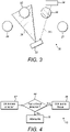
- FIG. 3 is a block diagram of a system, indicated generally by the reference numeral 30, in accordance with an example embodiment.
- the system 30 includes a first user device 32 (similar to the user device 12 described above) and first to fourth audio objects 34 to 37 (similar to the audio objects 14 to 17 described above). As shown in Figure 3 , the user device 32 is directed towards the second audio object 35, such that an audio focus beam 38 is directed towards the second audio object.
- the system 30 also includes a second user device 39 (such as a mobile communication device) that may be similar to the first user device 32 described above.
- the second user device 39 is at or near the third audio object 36.
- the second user device 39 sends a message (labelled 39a in Figure 4 ) to the first user device 32 requesting that the normal audio focus arrangement be suspended in the direction of the second user device 39.
- the message 39a sent from the second user device 39 to the first user device 32 may be used to prevent the audio focus arrangement described above from being applied in the direction of the noisy third audio object 36.
- the message 39a may take many forms.
- the message 39a may make use of local communication protocols, such as Bluetooth ® to transmit messages to other user devices (such as the first user device 32) in the vicinity of the second user device 39.
- local communication protocols such as Bluetooth ®
- Bluetooth ® to transmit messages to other user devices (such as the first user device 32) in the vicinity of the second user device 39.
- the skilled person will be aware of many other suitable message formats.
- the width of the audio focus beam 38 in the system 30 may be a definable parameter and may, for example, be set by a second user device 39. Alternatively, that parameter could be pre-set or set in some other way.
- FIG 4 is a flow chart showing an algorithm, indicated generally by the reference numeral 40, in accordance with an example embodiment.
- the algorithm 40 starts at operation 42, where the focus direction of the first user device 32 is determined.
- the direction identified in operation 42 is an audio focus direction unless a user device (such as the second user device 39) has requested that audio focus not be applied in the relevant direction.
- the focus direction determined at operation 42 may be a camera focus direction of the user device 32, but this is not essential to all embodiments.
- the focus direction may be an audio focus direction of the user device 32 (regardless of the existence or direction of a camera focus direction).
- the algorithm 40 moves to operation 46, where the normal audio focus is used, such that audio in the relevant direction captured by the user device 32 is amplified. If the direction determined in operation 42 is not an audio focus direction, then the algorithm moves to operation 48, where the captured audio in the relevant direction is attenuated (or, in some embodiments, not amplified).
- the message 39a described above may be sent from the second user device 39 to the first user device 32 in a number of ways.
- the user of the device 39 (such as a parent of the child that forms the audio object 36) may select an 'unhear me' option on the second user device 39, which causes the message 39a to be output using the Bluetooth ® standard, or some other messaging scheme.
- the skilled person will be aware of many other suitable mechanisms for sending such a message.
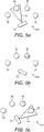
- FIGS. 5a, 5b and 5c are block diagrams of a system, indicated generally by the reference numerals 50a, 50b and 50c respectively, in accordance with an example embodiment.
- the systems 50a, 50b and 50c include the first to fourth audio objects 34 to 37 described above and also include a user device 52 (similar to the user devices 2, 12 and 32 described above).
- the user device 52 is shown performing a sweep such that the user device is directed towards the second object 35 ( Figure 5a ), the third object 36 ( Figure 5b ) and the fourth object 37 ( Figure 5c ) in turn.
- the third object 36 is deemed to be a noisy object.
- the operation 44 in the algorithm 40 is answered in the negative (such that the algorithm 40 moves to operation 48).
- the operation 44 is answered in the positive (such that the algorithm 40 moves to operation 46).
- the user device 52 When the user device 52 is directed towards the second audio object 35 (as shown in Figure 5a ), the user device 52 is directed in an audio focus direction. Operation 46 of the algorithm 40 is implemented by the provision of an audio focus beam 54 that is centred on the second audio object 35, such that audio from the second audio object is amplified. When the user device 52 is directed towards the third audio object 36 (as shown in Figure 5b ), the user device 52 is not directed in an audio focus direction. Operation 48 of the algorithm 40 is implemented by not providing an audio focus beam, such that audio from the third audio object is not boosted. In an alternative embodiment, the audio from the third audio object 36 may be attenuated (rather than simply not being boosted as indicated in Figure 5b ).
- Operation 46 of the algorithm 40 is implemented by the provision of an audio focus beam 56 that is centred on the fourth audio object 37, such that audio from the fourth audio object is amplified.
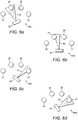
- Figures 6a, 6b, 6c and 6d are block diagrams of a system, indicated generally by the reference numerals 60a, 60b, 60c and 6od respectively, in accordance with an example embodiment.
- the systems 60a, 60b, 60c and 6od include the first to fourth audio objects 34 to 37 described above and also include a user device 62 (similar to the user devices 2, 12, 32 and 52 described above).
- the user device 62 is shown performing a sweep such that the user device is successively directed towards the second object 35 ( Figure 6a ), between the second and third objects ( Figure 6b ), between the third and fourth objects ( Figure 6c ) and towards the fourth object 37 ( Figure 6d ).
- the third object 36 is deemed to be a noisy object.
- the operation 44 in the algorithm 40 is answered in the negative (such that the algorithm 40 moves to operation 48).
- the operation 44 is answered in the positive (such that the algorithm 40 moves to operation 46).
- the user device 62 When the user device 62 is directed towards the second audio object 35 (as shown in Figure 6a ), the user device 62 is directed in an audio focus direction. Operation 46 of the algorithm 40 is implemented by the provision of an audio focus beam 63 that is centred on the second audio object 35, such that audio from the second audio object is amplified.
- an audio focus beam 64 is provided for the area that is in an audio focus direction.
- the audio focus beam 64 is narrower than the audio focus beam 63.
- an audio focus beam 65 is provided for the area that is in an audio focus direction.
- the audio focus beam 65 is narrower than the audio focus beam 63.
- the user device 62 When the user device 62 is directed towards the fourth audio object 47 (as shown in Figure 6d ), the user device 62 is directed in an audio focus direction. Operation 46 of the algorithm 40 is implemented by the provision of an audio focus beam 66 that is centred on the fourth audio object 37, such that audio from the fourth audio object is amplified.
- the audio focus beam may be disabled entirely.
- a similar arrangement may be provided in the system 60a to 60d described above. This is not essential to in all embodiments.
- FIG. 7 is a block diagram of a system, indicated generally by the reference numeral 70, in accordance with an example embodiment.
- the system 70 includes the first to fourth audio objects 34 to 37 described above and also include a user device 72 (similar to the user devices 2, 12, 32, 52 and 62 described above). In Figure 7 , the user device 72 is shown directed towards the third object 36.
- the third object 36 is deemed to be a noisy object.
- the operation 44 in the algorithm 40 is answered in the negative (such that the algorithm 40 moves to operation 48).
- the operation 44 is answered in the positive (such that the algorithm 40 moves to operation 46).
- the width of the portion missing from the audio focus beam 74 could be a definable parameter and may, for example, be set by a remote device (such as the remote device 39 described above). Alternatively, that parameter could be pre-set.
- the system 30 includes a second user device 39 (such as a mobile communication device) that is used to send a message (labelled 39a in Figure 4 ) to the first user device 32 requesting that the normal audio focus arrangement be suspended in the direction of the second user device 39.
- a second user device 39 such as a mobile communication device
- a similar arrangement may be provided in any of the systems 50, 60 or 70 described above.
- FIG 8 is a flow chart showing an algorithm, indicated generally by the reference numeral 80, in accordance with an example embodiment.
- the algorithm 80 starts at operation 82 where a second user device (such as the user device 39 described above) sends an 'unhear me' message to the first user device (such as any of the user devices 2, 12, 32, 52, 62, 72 described above).
- a second user device such as the user device 39 described above
- the first user device such as any of the user devices 2, 12, 32, 52, 62, 72 described above.
- an attenuate (or similar) flag is set in operation 84.
- the attenuate flag 84 may be associated with the direction of the user device 39 such that operation 44 of the algorithm 40 can be implemented by determining whether an attenuate flag has been set for the direction identified in operation 42.
- this functionality could be implemented in many different ways.
- not all embodiments include an attenuation - in many examples described herein unamplified directions are neither amplified nor attenuated.
- FIG. 9 is a flow chart showing an algorithm, indicated generally by the reference numeral 90, in accordance with an example embodiment.
- the algorithm 90 starts at operation 92 where a second user device (such as the user device 39 described above) sends a 'normal' message to the first user device (such as the any of the user devices 2, 12, 32, 52, 62, 72 described above).
- a second user device such as the user device 39 described above
- the first user device such as the any of the user devices 2, 12, 32, 52, 62, 72 described above.
- an attenuate (or similar) flag is cleared in operation 94.
- the second user device may take many forms.
- the second user device could be a mobile communication device, such as a mobile phone.
- the second user device may be a wearable device, such as a watch or a fitness monitor.
- the principles described herein are not restricted to dealing with issues of noise.
- the 'unhear me' arrangement may be used for privacy purposes.
- a person may be having a conversation that is not related to a scene being captured by the first user device 2, 12, 32, 52, 62, 72.
- the 'unhear me' setting described herein can be used to attenuate (or at least not amplify) such a conversation.
- a user may receive a telephone call on a user device (such as the second user device 39). In order to keep that telephone call private, the user may make use of the 'unhear me' feature described herein to prevent sounds from that call being captured by the first user device.
- a mobile device receiving or initiating a telephone call will indicate an 'unhear me' control message to all nearby mobile devices.
- the 'unhear me' control message may be output automatically by the mobile device when a telephone call is received or initiated.
- the embodiments described above relate to controlling the use of an audio focus arrangement of a user device when capturing audio data. It is also possible to use the principles described herein to modify an audio focus arrangement in different ways.
- FIG 10 is a block diagram of a system, indicated generally by the reference numeral 100, in accordance with an example embodiment.
- the system 100 includes a first user device 102 (similar to the user devices 2, 12, 34, 56, 62 and 72 described above) and the first to fourth audio objects 104 to 107 (similar to the audio objects 14 and 34, 15 and 35, 16 and 36, and 17 and 37 respectively, as described above).
- the first user device 102 is directed towards the first audio object 104, such that a first audio focus beam 110 is directed towards the first audio object.
- the first audio focus beam 110 is typically used to amplify audio in a direction of orientation of the first user device 102.
- the first user device 102 can be moved to capture audio and video in different directions, with the audio being amplified in the direction in which the video images are being taken at the time.
- the system 100 also includes a second user device 109 (similar to the user device 39 described above).
- the second user device 109 is at or near the third audio object 106.
- the second user device 109 sends a message (labelled 109a in Figure 10 ) to the first user device 102.
- the second user device 109 can be used to instruct the first user device 102 to boost audio coming from the direction of the second user device.
- a second audio focus beam 112 is shown that is directed towards the second user device 109 (and hence towards the third audio object 106).
- FIG 11 is a flow chart showing an algorithm, indicated generally by the reference numeral 120, in accordance with an example embodiment.
- the algorithm 120 starts at operation 122, where the direction from which audio detected in the system 100 is determined.
- it is determined whether the direction determined in operation 122 is within an audio focus beam e.g. the first audio focus beam 110 or the second audio focus beam 112 described above. If the direction determined in operation 122 is within an audio focus beam, the algorithm moves to operation 126, where the relevant audio is amplified, before terminating at operation 128. Otherwise, the algorithm terminates at operation 128 without implementing the amplification operation 126.
- an audio focus beam e.g. the first audio focus beam 110 or the second audio focus beam 112 described above.
- the message 109a described above may be sent from the second user device 109 to the first user device 102 in a number of ways.
- the user of the device 109 (such as a parent of the child that forms the audio object 36) may select an 'hear me' option on the second user device 109, which causes the message 109a to be output using the Bluetooth ® standard, or some other messaging scheme.
- the skilled person will be aware of many other suitable mechanisms for sending such a message.
- FIG 12 is a flow chart showing an algorithm, indicated generally by the reference numeral 130, in accordance with an example embodiment.
- the algorithm 130 starts at operation 132 where a second user device (such as the user device 109 described above) sends a 'hear me' message to the first user device (such as the first user device 102).
- a boost (or similar) flag is set in operation 134.
- the boost flag 134 may be associated with the direction of the second user device 109 such that audio data received at the first user device 102 in the direction indicated in the boost flag is boosted.
- the boost flag may therefore be used in the operation 124 of the algorithm 120 described above.
- this functionality could be implemented in many different ways.
- the direction of the second user device relative to the first user device is deemed to be the relevant direction for the instruction.
- the message sent by the second user device 39 or 109 may include direction, location or some other data, such that the second user device 39 or 109 can be used to modify the audio amplification functionality of the first user device in some other direction.
- the second user device 39 may send a message 39a to the first user device 32 that the second object 35 is a noisy object.
- the operation 44 would be answered in the negative when the first user device 32 is directed towards the second object 35.
- the second user device 109 may send a message 109a to the first user device 102 that the fourth object 107 should be amplified such that audio coming from the fourth user device 107 would be identified in operation 124 and amplified in operation 126.
- the algorithm 40 described above may be extended such that multiple areas are defined for which the audio should be attenuated (or at least not amplified).
- the algorithm 120 may be extended such that multiple area are defined for which audio should be amplified.
- the algorithms 40 and 120 described above may be combined such one or more areas may be defined for which audio should be attenuated (or at least not amplified) and one or more areas may be defined for which audio should be boosted.
- a first user may use a first user device (such as any one of the user devices 2, 12, 32, 52, 62, 72 or 102) to obtain audio data (and optionally also video images).
- a second user may use a second user device (such as the user device 39 or 109) to define audio boosting and/or audio attenuation areas within a defined space (such audio boosting and/or audio attenuation being the boosting or attenuation of the audio content captured by the first user device).
- the first user can concentrate on capturing the audio data (and, optionally, video data), whilst the second user can concentrate on the appropriate audio requirements (such as attenuating audio in the direction of a crying child or boosting audio in the direction of someone giving a speech).
- the second user may define zones in which audio focus should not be applied (e.g. due to one or more noisy or crying children) and/or may define one or more zones, other than the orientation direction of the first user device, in which audio focus should be applied (e.g. the direction from which a parent is singing to the children at the party).
- a user may make use of a remote device (such as the second user device 39 or 109) to indicate a noise source.
- a remote device such as the second user device 39 or 109
- an audio analysis engine may be used to automatically detect noise sources.
- such an audio analysis engine may analyse the content of its closest sounds sources and compare the obtained pattern to a database of noise sources and at least one threshold level. This may allow for automatic creation and sending of messages such as the 'unhear me' message 82 discussed above.
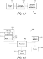
- FIG 13 is a flow chart showing an algorithm, indicated generally by the reference numeral 140, in accordance with an example embodiment.
- the algorithm 140 starts at operation 142, where audio data is received at a first user device.
- the audio data may be obtained from multiple directions.
- instructions are received at the first user device, for example from one or more remote device (e.g. the second user devices 39 or 109 described above).
- an audio focus arrangement is generated.
- the audio focus arrangement may be dependent on an orientation direction of the first user device and may be modified in accordance with the instructions from the remote device.
- At least some of the embodiments described herein may make use of spatial audio techniques in which an array of microphones is used to capture a sound scene and subjected to parametric spatial audio processing so that, during rendering, sounds are presented so that sounds are heard as if coming from directions around the user that match video recordings.
- Such techniques are known, for example, in virtual reality or augmented reality applications.
- Such spatial audio processing may involve estimating the directional portion of the sound scene and the ambient portion of the sound scene.
- FIG 14 is a schematic diagram of components of one or more of the modules described previously (e.g. implementing some or all of the operations of the algorithms 80 and 120 described above), which hereafter are referred to generically as processing systems 300.
- a processing system 300 may have a processor 302, a memory 304 closely coupled to the processor and comprised of a RAM 314 and ROM 312, and, optionally, user input 310 and a display 318.
- the processing system 300 may comprise one or more network interfaces 308 for connection to a network, e.g. a modem which may be wired or wireless.
- the processor 302 is connected to each of the other components in order to control operation thereof.
- the memory 304 may comprise a non-volatile memory, such as a hard disk drive (HDD) or a solid state drive (SSD).
- the ROM 312 of the memory 304 stores, amongst other things, an operating system 315 and may store software applications 316.
- the RAM 314 of the memory 304 is used by the processor 302 for the temporary storage of data.
- the operating system 315 may contain code which, when executed by the processor implements aspects of the algorithms 40, 80, 90, 120, 130 and 140 described above.
- the processor 302 may take any suitable form. For instance, it may be a microcontroller, plural microcontrollers, a processor, or plural processors.
- the processing system 300 may be a standalone computer, a server, a console, or a network thereof.
- the processing system 300 may also be associated with external software applications. These may be applications stored on a remote server device and may run partly or exclusively on the remote server device. These applications may be termed cloud-hosted applications.
- the processing system 300 maybe in communication with the remote server device in order to utilize the software application stored there.
- Figures 15a and 15b show tangible media, respectively a removable memory unit 365 and a compact disc (CD) 368, storing computer-readable code which when run by a computer may perform methods according to embodiments described above.
- the removable memory unit 365 may be a memory stick, e.g. a USB memory stick, having internal memory 366 storing the computer-readable code.
- the memory 366 may be accessed by a computer system via a connector 367.
- the CD 368 may be a CD-ROM or a DVD or similar. Other forms of tangible storage media may be used.
- Embodiments of the present invention may be implemented in software, hardware, application logic or a combination of software, hardware and application logic.
- the software, application logic and/or hardware may reside on memory, or any computer media.
- the application logic, software or an instruction set is maintained on any one of various conventional computer-readable media.
- a "memory" or “computer-readable medium” may be any non-transitory media or means that can contain, store, communicate, propagate or transport the instructions for use by or in connection with an instruction execution system, apparatus, or device, such as a computer.
- references to, where relevant, "computer-readable storage medium”, “computer program product”, “tangibly embodied computer program” etc., or a “processor” or “processing circuitry” etc. should be understood to encompass not only computers having differing architectures such as single/multi-processor architectures and sequencers/parallel architectures, but also specialised circuits such as field programmable gate arrays FPGA, application specify circuits ASIC, signal processing devices and other devices.
- References to computer program, instructions, code etc. should be understood to express software for a programmable processor firmware such as the programmable content of a hardware device as instructions for a processor or configured or configuration settings for a fixed function device, gate array, programmable logic device, etc.
- circuitry refers to all of the following: (a) hardware-only circuit implementations (such as implementations in only analogue and/or digital circuitry) and (b) to combinations of circuits and software (and/or firmware), such as (as applicable): (i) to a combination of processor(s) or (ii) to portions of processor(s)/software (including digital signal processor(s)), software, and memory(ies) that work together to cause an apparatus, such as a server, to perform various functions) and (c) to circuits, such as a microprocessor(s) or a portion of a microprocessor(s), that require software or firmware for operation, even if the software or firmware is not physically present.
Description
- This specification relates to receiving audio data from multiple directions using a user device.
- When using a user device, such as a mobile communication device, to receive audio data regarding a scene, it is possible to move the user device such that different parts of the scene can be captured. An audio focus arrangement can be provided in which audio is boosted in the direction in which the user device is directed. This can lead to boosting of unwanted noise or to privacy concerns.
-
US 2012/0330653 describes a portable voice capture device comprising: an orientable arm with a first differential array of microphones comprising at least one pair of microphones, the directivity of said first array being arranged for sensing voice from a first direction depending on the orientation of said arm; a second differential array of microphones comprising at least one pair of microphones, the directivity of said second array being arranged for sensing noise from a second direction different from the first direction; a noise reduction circuit for providing a voice signal with reduced noise, based on the output of said first array and on the output of said second array. -
US 2010/0195836 describes a communication system, comprising: a transmission unit comprising at least two microphones, with a separate audio signals channel for each microphone, a first ear unit and, a second ear unit worn at the each side of the user's head, each ear unit comprising a receiver unit; the transmission unit comprising means for transmitting at least a first channel and a second channel of the audio signals to the first and second ear unit, at least one of the receiver units being capable of receiving the at least first and second audio signal channel, at least one of the ear units comprising audio signal processing means for generating processed audio signals received via the at least first and second audio signal channel, with the first ear unit and the second ear unit comprising means for stimulating the user's hearing at the right ear and the left ear, accordingly. - In a first aspect, this specification describes a method as claimed in
claim 8. - In a second aspect, this specification describes an apparatus as claimed in claim 1. In a third aspect, this specification describes a computer readable medium comprising program instructions as claimed in
claim 15. - Example embodiments will now be described, by way of non-limiting examples, with reference to the following schematic drawings, in which:
-
Figure 1 is a block diagram of a system in accordance with an example embodiment;Figures 2a and 2b are block diagrams of a system in accordance with an example embodiment; -
Figure 3 is a block diagram of a system in accordance with an example embodiment; -
Figure 4 is a flow chart showing an algorithm in accordance with an example embodiment; -
Figure 5a, 5b and 5c are block diagrams of a system in accordance with an example embodiment; -
Figure 6a, 6b, 6c and 6d are block diagrams of a system in accordance with an example embodiment; -
Figure 7 is a block diagram of a system in accordance with an example embodiment; -
Figures 8 and 9 are flow charts showing algorithms in accordance with example embodiments; -
Figure 10 is a block diagram of a system in accordance with an example embodiment; -
Figures 11 to 13 are flow charts showing algorithms in accordance with example embodiments; -
Figure 14 is a block diagram of components of a processing system in accordance with an exemplary embodiment; and -
Figures 15a and 15b show tangible media, respectively a removable memory unit and a compact disc (CD) storing computer-readable code which when run by a computer perform operations according to embodiments. -
Figure 1 is a block diagram of a system, indicated generally by the reference numeral 1, in accordance with an example embodiment. The system 1 comprises a first user device 2 (such as a mobile communication device), which first user device may be a multi-microphone capture device, such as a mobile device, used to make video and audio recordings (with a camera of thefirst user device 2 being used to capture video data and one or more microphones being used to capture audio data). The system 1 also comprises afirst audio source 4, asecond audio source 5, athird audio source 6 and afourth audio source 7. As shown inFigure 1 , thefirst user device 2 includes anaudio focus beam 8. Audio data from within theaudio focus beam 8 may be handled differently to audio data from outside the audio focus beam. For example, audio data within the audio focus beam may be amplified, whereas audio data outside the audio focus beam may not be amplified or may be attenuated. - As described further below, the
audio focus beam 8 is typically used to amplify audio recorded in a direction of orientation of thefirst user device 2. By way of example, in the example system 1, the audio focus beam is directed towards thethird audio source 6. Thus, for example, thefirst user device 2 can be moved to capture audio and video in different directions, with the audio being amplified in the direction in which the video images are being taken at the time. Moreover, in some example embodiments, video and audio data may be captured in different directions (providing, in effect, different video and audio focus beams). -
Figures 2a and 2b are highly schematic block diagrams of a system, indicated generally by thereference numerals systems first user device 12 and first tofourth audio sources 14 to 17. Thefirst user device 12 may be the same as theuser device 2 described above with reference toFigure 1 . - In the
system 20a, thefirst user device 12 is directed towards thesecond audio object 15. As shown inFigure 2a , thesystem 20a includes anaudio focus beam 22 that is centred on thesecond audio object 15. Similarly, in thesystem 20b, the first user device is directed towards thethird audio object 16. As shown in Figure 3b, thesystem 20b includes anaudio focus beam 24 that is centred on thethird audio object 16. - Consider the following arrangement in which the
third source 16 is a source of potentially disturbing sounds. By way of example, consider a children's party in which the first, second, third and fourth objects represent children at the party. Assume that thethird object 16 represents a child who is crying. Consider now a scenario in which theuser device 12 is being used to take a video and audio recording of the birthday party by sweeping the video recording across the audio objects (for example, from being focused on thesecond object 15 as shown inFigure 2a to being focused on thethird object 16 as shown inFigure 2b ). When thefirst user device 12 is directed towards the third object 16 (as shown inFigure 2b ), the audio focus arrangement described above with will amplify the audio from the crying child. (Note that the terms "amplify" and "boost" are used interchangeably in this document.) It may therefore be undesirable to implement the audio focus arrangement described above with reference to the system 1. -
Figure 3 is a block diagram of a system, indicated generally by thereference numeral 30, in accordance with an example embodiment. Thesystem 30 includes a first user device 32 (similar to theuser device 12 described above) and first tofourth audio objects 34 to 37 (similar to theaudio objects 14 to 17 described above). As shown inFigure 3 , theuser device 32 is directed towards thesecond audio object 35, such that anaudio focus beam 38 is directed towards the second audio object. - The
system 30 also includes a second user device 39 (such as a mobile communication device) that may be similar to thefirst user device 32 described above. Thesecond user device 39 is at or near thethird audio object 36. Thesecond user device 39 sends a message (labelled 39a inFigure 4 ) to thefirst user device 32 requesting that the normal audio focus arrangement be suspended in the direction of thesecond user device 39. Thus, as described in detail below, themessage 39a sent from thesecond user device 39 to thefirst user device 32 may be used to prevent the audio focus arrangement described above from being applied in the direction of the noisythird audio object 36. - The
message 39a may take many forms. By way of example, themessage 39a may make use of local communication protocols, such as Bluetooth® to transmit messages to other user devices (such as the first user device 32) in the vicinity of thesecond user device 39. The skilled person will be aware of many other suitable message formats. - It should be noted that the width of the
audio focus beam 38 in the system 30 (and the width of comparable audio focus beams in other embodiments) may be a definable parameter and may, for example, be set by asecond user device 39. Alternatively, that parameter could be pre-set or set in some other way. -
Figure 4 is a flow chart showing an algorithm, indicated generally by thereference numeral 40, in accordance with an example embodiment. Thealgorithm 40 starts atoperation 42, where the focus direction of thefirst user device 32 is determined. Next, atoperation 44, it is determined whether the focus direction is an audio focus direction. In one embodiment, the direction identified inoperation 42 is an audio focus direction unless a user device (such as the second user device 39) has requested that audio focus not be applied in the relevant direction. The focus direction determined atoperation 42 may be a camera focus direction of theuser device 32, but this is not essential to all embodiments. For example, the focus direction may be an audio focus direction of the user device 32 (regardless of the existence or direction of a camera focus direction). - In the event that the direction determined in
operation 42 is an audio focus direction, then thealgorithm 40 moves tooperation 46, where the normal audio focus is used, such that audio in the relevant direction captured by theuser device 32 is amplified. If the direction determined inoperation 42 is not an audio focus direction, then the algorithm moves tooperation 48, where the captured audio in the relevant direction is attenuated (or, in some embodiments, not amplified). - The
message 39a described above may be sent from thesecond user device 39 to thefirst user device 32 in a number of ways. For example, the user of the device 39 (such as a parent of the child that forms the audio object 36) may select an 'unhear me' option on thesecond user device 39, which causes themessage 39a to be output using the Bluetooth® standard, or some other messaging scheme. The skilled person will be aware of many other suitable mechanisms for sending such a message. - Many mechanisms exist for implementing the audio focus arrangement described above. Different arrangements are described below, by way of example, with references to
Figures 5 to 7 . -
Figures 5a, 5b and 5c are block diagrams of a system, indicated generally by thereference numerals - The
systems user devices Figures 5a to 5c , theuser device 52 is shown performing a sweep such that the user device is directed towards the second object 35 (Figure 5a ), the third object 36 (Figure 5b ) and the fourth object 37 (Figure 5c ) in turn. - Assume that the
third object 36 is deemed to be a noisy object. Thus, when theuser device 52 is directed towards thethird object 36, theoperation 44 in thealgorithm 40 is answered in the negative (such that thealgorithm 40 moves to operation 48). When theuser device 52 is directed in any other direction, then theoperation 44 is answered in the positive (such that thealgorithm 40 moves to operation 46). - When the
user device 52 is directed towards the second audio object 35 (as shown inFigure 5a ), theuser device 52 is directed in an audio focus direction.Operation 46 of thealgorithm 40 is implemented by the provision of anaudio focus beam 54 that is centred on thesecond audio object 35, such that audio from the second audio object is amplified. When theuser device 52 is directed towards the third audio object 36 (as shown inFigure 5b ), theuser device 52 is not directed in an audio focus direction.Operation 48 of thealgorithm 40 is implemented by not providing an audio focus beam, such that audio from the third audio object is not boosted. In an alternative embodiment, the audio from thethird audio object 36 may be attenuated (rather than simply not being boosted as indicated inFigure 5b ). - When the
user device 52 is directed towards the fourth audio object 37 (as shown inFigure 5c ), theuser device 52 is directed in an audio focus direction.Operation 46 of thealgorithm 40 is implemented by the provision of anaudio focus beam 56 that is centred on thefourth audio object 37, such that audio from the fourth audio object is amplified. - It can be seen in
Figures 5a to 5c that audio from the first, second andfourth objects algorithm 40 may enable the user device to be controlled to achieve this effect without requiring a user of that user device to change user device settings at the same time as capturing the audio (and possibly also visual) data. - There are many alternatives to the arrangement described above with reference to
Figures 5a to 5c . By way of example,Figures 6a, 6b, 6c and 6d are block diagrams of a system, indicated generally by thereference numerals - The
systems user devices Figures 6a to 6d , theuser device 62 is shown performing a sweep such that the user device is successively directed towards the second object 35 (Figure 6a ), between the second and third objects (Figure 6b ), between the third and fourth objects (Figure 6c ) and towards the fourth object 37 (Figure 6d ). - Assume, once again, that the
third object 36 is deemed to be a noisy object. Thus, when theuser device 62 is directed towards thethird object 36, theoperation 44 in thealgorithm 40 is answered in the negative (such that thealgorithm 40 moves to operation 48). When theuser device 62 is directed in any other direction, then theoperation 44 is answered in the positive (such that thealgorithm 40 moves to operation 46). - When the
user device 62 is directed towards the second audio object 35 (as shown inFigure 6a ), theuser device 62 is directed in an audio focus direction.Operation 46 of thealgorithm 40 is implemented by the provision of anaudio focus beam 63 that is centred on thesecond audio object 35, such that audio from the second audio object is amplified. - When the
user device 62 is directed between thesecond object 35 and the third object 36 (as shown inFigure 6b ), part of theuser device 62 is directed in an audio focus direction and part is not. As shown inFigure 6b , anaudio focus beam 64 is provided for the area that is in an audio focus direction. Thus, theaudio focus beam 64 is narrower than theaudio focus beam 63. - When the
user device 62 is directed between thethird object 36 and the fourth object 37 (as shown inFigure 6c ), part of theuser device 62 is directed in an audio focus direction and part is not. As shown inFigure 6c , anaudio focus beam 65 is provided for the area that is in an audio focus direction. Thus, theaudio focus beam 65 is narrower than theaudio focus beam 63. - When the
user device 62 is directed towards the fourth audio object 47 (as shown inFigure 6d ), theuser device 62 is directed in an audio focus direction.Operation 46 of thealgorithm 40 is implemented by the provision of anaudio focus beam 66 that is centred on thefourth audio object 37, such that audio from the fourth audio object is amplified. - As described above with reference to
Figure 5b , when the relevant user device (e.g. the user device 52) is directed towards a noisy object (e.g. the object 36), the audio focus beam may be disabled entirely. A similar arrangement may be provided in thesystem 60a to 60d described above. This is not essential to in all embodiments. -
Figure 7 is a block diagram of a system, indicated generally by thereference numeral 70, in accordance with an example embodiment. - The
system 70 includes the first to fourth audio objects 34 to 37 described above and also include a user device 72 (similar to theuser devices Figure 7 , theuser device 72 is shown directed towards thethird object 36. - Assume that the
third object 36 is deemed to be a noisy object. Thus, when theuser device 72 is directed towards thethird object 36, theoperation 44 in thealgorithm 40 is answered in the negative (such that thealgorithm 40 moves to operation 48). When theuser device 72 is directed in any other direction, then theoperation 44 is answered in the positive (such that thealgorithm 40 moves to operation 46). - In the
system 70, there is no audio focus beam directed towards thethird object 36, butaudio focus regions third object 36. (This can be considered to be anaudio focus beam 74 with the portion directed towards thethird object 36 omitted.) Thus, audio from all directions other than the direction of theobject 36 can be boosted. It should be noted that the width of the portion missing from theaudio focus beam 74 could be a definable parameter and may, for example, be set by a remote device (such as theremote device 39 described above). Alternatively, that parameter could be pre-set. - As described above with reference to
Figure 3 , thesystem 30 includes a second user device 39 (such as a mobile communication device) that is used to send a message (labelled 39a inFigure 4 ) to thefirst user device 32 requesting that the normal audio focus arrangement be suspended in the direction of thesecond user device 39. A similar arrangement may be provided in any of thesystems 50, 60 or 70 described above. -
Figure 8 is a flow chart showing an algorithm, indicated generally by thereference numeral 80, in accordance with an example embodiment. Thealgorithm 80 starts atoperation 82 where a second user device (such as theuser device 39 described above) sends an 'unhear me' message to the first user device (such as any of theuser devices operation 82, an attenuate (or similar) flag is set inoperation 84. - The
attenuate flag 84 may be associated with the direction of theuser device 39 such thatoperation 44 of thealgorithm 40 can be implemented by determining whether an attenuate flag has been set for the direction identified inoperation 42. Of course, this functionality could be implemented in many different ways. In particular, not all embodiments include an attenuation - in many examples described herein unamplified directions are neither amplified nor attenuated. -
Figure 9 is a flow chart showing an algorithm, indicated generally by thereference numeral 90, in accordance with an example embodiment. Thealgorithm 90 starts atoperation 92 where a second user device (such as theuser device 39 described above) sends a 'normal' message to the first user device (such as the any of theuser devices operation 92, an attenuate (or similar) flag is cleared inoperation 94. - The second user device may take many forms. For example, the second user device could be a mobile communication device, such as a mobile phone. However, this is not essential to all embodiments. For example, the second user device may be a wearable device, such as a watch or a fitness monitor.
- The principles described herein are not restricted to dealing with issues of noise. For example, the 'unhear me' arrangement may be used for privacy purposes. For example, a person may be having a conversation that is not related to a scene being captured by the
first user device - In some example embodiments, a mobile device receiving or initiating a telephone call will indicate an 'unhear me' control message to all nearby mobile devices. In such an embodiment, the 'unhear me' control message may be output automatically by the mobile device when a telephone call is received or initiated.
- The embodiments described above relate to controlling the use of an audio focus arrangement of a user device when capturing audio data. It is also possible to use the principles described herein to modify an audio focus arrangement in different ways.
-
Figure 10 is a block diagram of a system, indicated generally by thereference numeral 100, in accordance with an example embodiment. Thesystem 100 includes a first user device 102 (similar to theuser devices Figure 10 , thefirst user device 102 is directed towards thefirst audio object 104, such that a firstaudio focus beam 110 is directed towards the first audio object. - As described above, the first
audio focus beam 110 is typically used to amplify audio in a direction of orientation of thefirst user device 102. Thus, for example, thefirst user device 102 can be moved to capture audio and video in different directions, with the audio being amplified in the direction in which the video images are being taken at the time. - The
system 100 also includes a second user device 109 (similar to theuser device 39 described above). Thesecond user device 109 is at or near thethird audio object 106. Thesecond user device 109 sends a message (labelled 109a inFigure 10 ) to thefirst user device 102. As described further below, thesecond user device 109 can be used to instruct thefirst user device 102 to boost audio coming from the direction of the second user device. Thus, as shown inFigure 10 , a secondaudio focus beam 112 is shown that is directed towards the second user device 109 (and hence towards the third audio object 106). -
Figure 11 is a flow chart showing an algorithm, indicated generally by thereference numeral 120, in accordance with an example embodiment. Thealgorithm 120 starts atoperation 122, where the direction from which audio detected in thesystem 100 is determined. Next, atoperation 124, it is determined whether the direction determined inoperation 122 is within an audio focus beam (e.g. the firstaudio focus beam 110 or the secondaudio focus beam 112 described above). If the direction determined inoperation 122 is within an audio focus beam, the algorithm moves tooperation 126, where the relevant audio is amplified, before terminating atoperation 128. Otherwise, the algorithm terminates atoperation 128 without implementing theamplification operation 126. - The
message 109a described above may be sent from thesecond user device 109 to thefirst user device 102 in a number of ways. For example, the user of the device 109 (such as a parent of the child that forms the audio object 36) may select an 'hear me' option on thesecond user device 109, which causes themessage 109a to be output using the Bluetooth® standard, or some other messaging scheme. The skilled person will be aware of many other suitable mechanisms for sending such a message. -
Figure 12 is a flow chart showing an algorithm, indicated generally by thereference numeral 130, in accordance with an example embodiment. Thealgorithm 130 starts atoperation 132 where a second user device (such as theuser device 109 described above) sends a 'hear me' message to the first user device (such as the first user device 102). In response to the message received inoperation 132, a boost (or similar) flag is set in operation 134. - The boost flag 134 may be associated with the direction of the
second user device 109 such that audio data received at thefirst user device 102 in the direction indicated in the boost flag is boosted. The boost flag may therefore be used in theoperation 124 of thealgorithm 120 described above. Of course, this functionality could be implemented in many different ways. - In the
algorithms second user device second user device example system 30 described above with reference toFigure 3 , thesecond user device 39 may send amessage 39a to thefirst user device 32 that thesecond object 35 is a noisy object. Thus, theoperation 44 would be answered in the negative when thefirst user device 32 is directed towards thesecond object 35. In another example, in theexample system 100 described above with reference toFigure 10 , thesecond user device 109 may send amessage 109a to thefirst user device 102 that thefourth object 107 should be amplified such that audio coming from thefourth user device 107 would be identified inoperation 124 and amplified inoperation 126. - The
algorithm 40 described above may be extended such that multiple areas are defined for which the audio should be attenuated (or at least not amplified). Similarly, thealgorithm 120 may be extended such that multiple area are defined for which audio should be amplified. Furthermore, thealgorithms - Many implementations of the principles described herein are possible. By way of example, a first user may use a first user device (such as any one of the
user devices user device 39 or 109) to define audio boosting and/or audio attenuation areas within a defined space (such audio boosting and/or audio attenuation being the boosting or attenuation of the audio content captured by the first user device). - In this way, the first user can concentrate on capturing the audio data (and, optionally, video data), whilst the second user can concentrate on the appropriate audio requirements (such as attenuating audio in the direction of a crying child or boosting audio in the direction of someone giving a speech). Returning to example of a children's party, the second user may define zones in which audio focus should not be applied (e.g. due to one or more noisy or crying children) and/or may define one or more zones, other than the orientation direction of the first user device, in which audio focus should be applied (e.g. the direction from which a parent is singing to the children at the party).
- In some implementations, a user may make use of a remote device (such as the
second user device 39 or 109) to indicate a noise source. This is not essential. For example, an audio analysis engine may be used to automatically detect noise sources. For example, such an audio analysis engine may analyse the content of its closest sounds sources and compare the obtained pattern to a database of noise sources and at least one threshold level. This may allow for automatic creation and sending of messages such as the 'unhear me'message 82 discussed above. -
Figure 13 is a flow chart showing an algorithm, indicated generally by thereference numeral 140, in accordance with an example embodiment. Thealgorithm 140 starts atoperation 142, where audio data is received at a first user device. The audio data may be obtained from multiple directions. Atoperation 144, instructions are received at the first user device, for example from one or more remote device (e.g. thesecond user devices operation 146, an audio focus arrangement is generated. For example, the audio focus arrangement may be dependent on an orientation direction of the first user device and may be modified in accordance with the instructions from the remote device. - At least some of the embodiments described herein may make use of spatial audio techniques in which an array of microphones is used to capture a sound scene and subjected to parametric spatial audio processing so that, during rendering, sounds are presented so that sounds are heard as if coming from directions around the user that match video recordings. Such techniques are known, for example, in virtual reality or augmented reality applications. Such spatial audio processing may involve estimating the directional portion of the sound scene and the ambient portion of the sound scene.
- For completeness,
Figure 14 is a schematic diagram of components of one or more of the modules described previously (e.g. implementing some or all of the operations of thealgorithms systems 300. Aprocessing system 300 may have aprocessor 302, amemory 304 closely coupled to the processor and comprised of aRAM 314 andROM 312, and, optionally, user input 310 and adisplay 318. Theprocessing system 300 may comprise one ormore network interfaces 308 for connection to a network, e.g. a modem which may be wired or wireless. - The
processor 302 is connected to each of the other components in order to control operation thereof. - The
memory 304 may comprise a non-volatile memory, such as a hard disk drive (HDD) or a solid state drive (SSD). TheROM 312 of thememory 304 stores, amongst other things, anoperating system 315 and may storesoftware applications 316. TheRAM 314 of thememory 304 is used by theprocessor 302 for the temporary storage of data. Theoperating system 315 may contain code which, when executed by the processor implements aspects of thealgorithms - The
processor 302 may take any suitable form. For instance, it may be a microcontroller, plural microcontrollers, a processor, or plural processors. - The
processing system 300 may be a standalone computer, a server, a console, or a network thereof. - In some embodiments, the
processing system 300 may also be associated with external software applications. These may be applications stored on a remote server device and may run partly or exclusively on the remote server device. These applications may be termed cloud-hosted applications. Theprocessing system 300 maybe in communication with the remote server device in order to utilize the software application stored there. -
Figures 15a and 15b show tangible media, respectively aremovable memory unit 365 and a compact disc (CD) 368, storing computer-readable code which when run by a computer may perform methods according to embodiments described above. Theremovable memory unit 365 may be a memory stick, e.g. a USB memory stick, havinginternal memory 366 storing the computer-readable code. Thememory 366 may be accessed by a computer system via aconnector 367. TheCD 368 may be a CD-ROM or a DVD or similar. Other forms of tangible storage media may be used. - Embodiments of the present invention may be implemented in software, hardware, application logic or a combination of software, hardware and application logic. The software, application logic and/or hardware may reside on memory, or any computer media. In an example embodiment, the application logic, software or an instruction set is maintained on any one of various conventional computer-readable media. In the context of this document, a "memory" or "computer-readable medium" may be any non-transitory media or means that can contain, store, communicate, propagate or transport the instructions for use by or in connection with an instruction execution system, apparatus, or device, such as a computer.
- Reference to, where relevant, "computer-readable storage medium", "computer program product", "tangibly embodied computer program" etc., or a "processor" or "processing circuitry" etc. should be understood to encompass not only computers having differing architectures such as single/multi-processor architectures and sequencers/parallel architectures, but also specialised circuits such as field programmable gate arrays FPGA, application specify circuits ASIC, signal processing devices and other devices. References to computer program, instructions, code etc. should be understood to express software for a programmable processor firmware such as the programmable content of a hardware device as instructions for a processor or configured or configuration settings for a fixed function device, gate array, programmable logic device, etc.
- As used in this application, the term "circuitry" refers to all of the following: (a) hardware-only circuit implementations (such as implementations in only analogue and/or digital circuitry) and (b) to combinations of circuits and software (and/or firmware), such as (as applicable): (i) to a combination of processor(s) or (ii) to portions of processor(s)/software (including digital signal processor(s)), software, and memory(ies) that work together to cause an apparatus, such as a server, to perform various functions) and (c) to circuits, such as a microprocessor(s) or a portion of a microprocessor(s), that require software or firmware for operation, even if the software or firmware is not physically present.
- It will be appreciated that the above described example embodiments are purely illustrative and are not limiting on the scope of the invention. Other variations and modifications will be apparent to persons skilled in the art upon reading the present specification.
- It is also noted herein that while the above describes various examples, these descriptions should not be viewed in a limiting sense. Rather, there are several variations and modifications which may be made without departing from the scope of the present invention as defined in the appended claims.
Claims (15)
- An apparatus comprising:means for receiving audio data from multiple directions at the apparatus, wherein the apparatus is a first user device;means for receiving instructions from a remote device, wherein the remote device is a second user device (39, 109);means adapted for generating an audio focus arrangement, wherein the audio focus arrangement is a direction-dependent amplification of the received audio data and wherein the audio focus arrangement is dependent on an orientation direction of the apparatus and the means adapted for generating the audio focus arrangement are adapted to modify the audio focus arrangement in accordance with the instructions from the remote device; andmeans for amplifying the received audio data when the received audio data is received from a direction within the audio focus arrangement,wherein the means adapted for generating the audio focus arrangement are adapted to modify the audio focus arrangement by:when said instructions comprise a first message (39a), determining a direction of said remote device relative to said first user device and the orientation direction of the first user device and modifying the audio focus for not amplifying the audio data received from the direction of the said remote device relative to said first user device if it is determined that the first user device is directed towards the second user device; orwhen said instructions comprise a second message (109a), determining a direction of said remote device relative to said first user device and modifying the audio focus for amplifying audio data received from the direction of the said remote device relative to said first user device.
- An apparatus as claimed in claim 1, further comprising means for providing an audio output based on the received audio data and the generated audio focus arrangement.
- An apparatus as claimed in claim 1 or claim 2, wherein the generated audio focus arrangement includes amplifying the audio data when the audio data is in the orientation direction of the user device, unless the instructions from the remote device instruct otherwise.
- An apparatus as claimed in any one of claims 1 to 3, wherein the means for generating the audio focus arrangement is further configured to modify the audio focus arrangement in a direction indicated by the remote device.
- An apparatus as claimed in any one of the preceding claims, wherein the audio focus arrangement is configured to perform one or more of:attenuating audio from a first direction;neither attenuating nor amplifying audio from the first direction; andamplifying audio from the first direction.
- An apparatus as claimed in any one of the preceding claims, wherein the apparatus is a mobile communication device.
- An apparatus as claimed in any one of the preceding claims, further comprising:means for receiving instructions at the first user device from one or more further remote devices; andmeans for modifying the audio focus arrangement in accordance with the instructions from the one or more further remote devices.
- A method comprising:receiving (142) audio data from multiple directions at a first user device (2, 12, 32, 52, 62, 72, 102);receiving (144) instructions at the first user device from a remote device, wherein the remote device is a second user device (39, 109);generating (146) an audio focus arrangement, wherein the audio focus arrangement is a direction-dependent amplification of the received audio data and wherein the audio focus arrangement is dependent on an orientation direction of the first user device and is modified in accordance with the instructions from the remote device; andamplifying the audio data when the audio data is received from a direction within the audio focus arrangement,wherein modifying the audio focus arrangement comprises:when said instructions comprise a first message (39a), determining a direction of said remote device relative to said first user device and the orientation direction of the first user device and modifying the audio focus arrangement for not amplifying audio data received from the direction of the said remote device relative to said first user device if it is determined that the first user device is directed towards the second user device; orwhen said instructions comprise a second message (109a), determining a direction of said remote device relative to said first user device and modifying the audio focus arrangement for amplifying
audio data received from the direction of the said remote device relative to said first user device. - A method as claimed in claim 8, further comprising generating an audio output based on the received audio data and the generated audio focus arrangement.
- A method as claimed in claim 8 or claim 9, wherein the generated audio focus arrangement includes amplifying the audio data when the audio data is in the orientation direction of the user device, unless the instructions from the remote device instruct otherwise.
- A method as claimed in any one of claims 8 to 10, wherein the generated audio focus arrangement includes amplifying the audio data when the audio data is in a direction indicated by the remote device.
- A method as claimed in any one of claims 8 to 11, wherein modifying the audio focus arrangement includes one of:attenuating audio from a first direction;neither attenuating nor amplifying audio from the first direction; andamplifying audio from the first direction.
- A method as claimed in any one of clams 8 to 12, wherein the instructions are generated automatically by the remote device.
- A method as claimed in any one of claims 8 to 13, further comprising:receiving instructions at the first user device from one or more further remote devices; andmodifying the audio focus arrangement in accordance with the instructions from the one or more further remote devices.
- A computer readable medium comprising program instructions for causing an apparatus to perform at least the following:receive audio data from multiple directions at a first user device;receive instructions at the first user device from a remote device, wherein the remote device is a second user device;generate an audio focus arrangement, wherein the audio focus arrangement is a direction-dependent amplification of the received audio data and wherein the audio focus arrangement is dependent on an orientation direction of the first user device and is modified in accordance with the instructions from the remote device; andamplify the audio data when the audio data is received from a direction within the audio focus arrangement,wherein the audio focus arrangement is modified by:when said instructions comprise a first message (39a), determining a direction of said remote device relative to said first user device and the orientation direction of the first user device and modifying the audio focus arrangement for not amplifying audio data received from the direction of the said remote device relative to said first user device if it is determined that the first user device is directed towards the second user device; orwhen said instructions comprise a second message (109a), determining a direction of said remote device relative to said first user device and modifying the audio focus arrangement for amplifying audio data received from the direction of the said remote device relative to said first user device.
Priority Applications (3)
| Application Number | Priority Date | Filing Date | Title |
|---|---|---|---|
| EP18157327.0A EP3528509B9 (en) | 2018-02-19 | 2018-02-19 | Audio data arrangement |
| PCT/IB2019/051040 WO2019159050A1 (en) | 2018-02-19 | 2019-02-08 | Audio data arrangement |
| US16/962,534 US11290812B2 (en) | 2018-02-19 | 2019-02-08 | Audio data arrangement |
Applications Claiming Priority (1)
| Application Number | Priority Date | Filing Date | Title |
|---|---|---|---|
| EP18157327.0A EP3528509B9 (en) | 2018-02-19 | 2018-02-19 | Audio data arrangement |
Publications (3)
| Publication Number | Publication Date |
|---|---|
| EP3528509A1 EP3528509A1 (en) | 2019-08-21 |
| EP3528509B1 EP3528509B1 (en) | 2022-08-24 |
| EP3528509B9 true EP3528509B9 (en) | 2023-01-11 |
Family
ID=61274065
Family Applications (1)
| Application Number | Title | Priority Date | Filing Date |
|---|---|---|---|
| EP18157327.0A Active EP3528509B9 (en) | 2018-02-19 | 2018-02-19 | Audio data arrangement |
Country Status (3)
| Country | Link |
|---|---|
| US (1) | US11290812B2 (en) |
| EP (1) | EP3528509B9 (en) |
| WO (1) | WO2019159050A1 (en) |
Families Citing this family (1)
| Publication number | Priority date | Publication date | Assignee | Title |
|---|---|---|---|---|
| US11405722B2 (en) * | 2019-09-17 | 2022-08-02 | Gopro, Inc. | Beamforming for wind noise optimized microphone placements |
Family Cites Families (8)
| Publication number | Priority date | Publication date | Assignee | Title |
|---|---|---|---|---|
| JP5082327B2 (en) * | 2006-08-09 | 2012-11-28 | ソニー株式会社 | Audio signal processing apparatus, audio signal processing method, and audio signal processing program |
| EP2116102B1 (en) * | 2007-02-14 | 2011-05-18 | Phonak AG | Wireless communication system and method |
| US8170241B2 (en) * | 2008-04-17 | 2012-05-01 | Intouch Technologies, Inc. | Mobile tele-presence system with a microphone system |
| CH702399B1 (en) * | 2009-12-02 | 2018-05-15 | Veovox Sa | Apparatus and method for capturing and processing the voice |
| US8525868B2 (en) * | 2011-01-13 | 2013-09-03 | Qualcomm Incorporated | Variable beamforming with a mobile platform |
| EP2680616A1 (en) * | 2012-06-25 | 2014-01-01 | LG Electronics Inc. | Mobile terminal and audio zooming method thereof |
| US10531219B2 (en) * | 2017-03-20 | 2020-01-07 | Nokia Technologies Oy | Smooth rendering of overlapping audio-object interactions |
| US10410492B2 (en) * | 2017-09-18 | 2019-09-10 | Comcast Cable Communications, Llc | Automatic presence simulator for security systems |
-
2018
- 2018-02-19 EP EP18157327.0A patent/EP3528509B9/en active Active
-
2019
- 2019-02-08 WO PCT/IB2019/051040 patent/WO2019159050A1/en active Application Filing
- 2019-02-08 US US16/962,534 patent/US11290812B2/en active Active
Also Published As
| Publication number | Publication date |
|---|---|
| EP3528509A1 (en) | 2019-08-21 |
| US11290812B2 (en) | 2022-03-29 |
| EP3528509B1 (en) | 2022-08-24 |
| WO2019159050A1 (en) | 2019-08-22 |
| US20200382864A1 (en) | 2020-12-03 |
Similar Documents
| Publication | Publication Date | Title |
|---|---|---|
| US11095985B2 (en) | Binaural recording for processing audio signals to enable alerts | |
| US10694312B2 (en) | Dynamic augmentation of real-world sounds into a virtual reality sound mix | |
| US10848889B2 (en) | Intelligent audio rendering for video recording | |
| US20100254543A1 (en) | Conference microphone system | |
| US10616681B2 (en) | Suppressing ambient sounds | |
| US10497356B2 (en) | Directionality control system and sound output control method | |
| US20220174395A1 (en) | Auditory augmented reality using selective noise cancellation | |
| JP6447976B2 (en) | Directivity control system and audio output control method | |
| EP3528509B9 (en) | Audio data arrangement | |
| JP2013110633A (en) | Transoral system | |
| JP2011254400A (en) | Image and voice recording device | |
| JP2014175944A (en) | Television conference apparatus, control method of the same, and program | |
| US20210274305A1 (en) | Use of Local Link to Support Transmission of Spatial Audio in a Virtual Environment | |
| JP6569853B2 (en) | Directivity control system and audio output control method | |
| WO2010088952A1 (en) | Conference microphone system | |
| US20220337945A1 (en) | Selective sound modification for video communication | |
| WO2018227560A1 (en) | Method and system for controlling earphone | |
| WO2023228713A1 (en) | Sound processing device and method, information processing device, and program | |
| US11937071B2 (en) | Augmented reality system | |
| EP3706432A1 (en) | Processing multiple spatial audio signals which have a spatial overlap | |
| JP2024056580A (en) | Information processing device, control method thereof, and program | |
| JP2016219966A (en) | Directivity control system and voice output control method |
Legal Events
| Date | Code | Title | Description |
|---|---|---|---|
| PUAI | Public reference made under article 153(3) epc to a published international application that has entered the european phase |
Free format text: ORIGINAL CODE: 0009012 |
|
| STAA | Information on the status of an ep patent application or granted ep patent |
Free format text: STATUS: THE APPLICATION HAS BEEN PUBLISHED |
|
| AK | Designated contracting states |
Kind code of ref document: A1 Designated state(s): AL AT BE BG CH CY CZ DE DK EE ES FI FR GB GR HR HU IE IS IT LI LT LU LV MC MK MT NL NO PL PT RO RS SE SI SK SM TR |
|
| AX | Request for extension of the european patent |
Extension state: BA ME |
|
| RAP1 | Party data changed (applicant data changed or rights of an application transferred) |
Owner name: NOKIA TECHNOLOGIES OY |
|
| STAA | Information on the status of an ep patent application or granted ep patent |
Free format text: STATUS: REQUEST FOR EXAMINATION WAS MADE |
|
| 17P | Request for examination filed |
Effective date: 20200210 |
|
| RBV | Designated contracting states (corrected) |
Designated state(s): AL AT BE BG CH CY CZ DE DK EE ES FI FR GB GR HR HU IE IS IT LI LT LU LV MC MK MT NL NO PL PT RO RS SE SI SK SM TR |
|
| STAA | Information on the status of an ep patent application or granted ep patent |
Free format text: STATUS: EXAMINATION IS IN PROGRESS |
|
| 17Q | First examination report despatched |
Effective date: 20201022 |
|
| STAA | Information on the status of an ep patent application or granted ep patent |
Free format text: STATUS: EXAMINATION IS IN PROGRESS |
|
| GRAP | Despatch of communication of intention to grant a patent |
Free format text: ORIGINAL CODE: EPIDOSNIGR1 |
|
| STAA | Information on the status of an ep patent application or granted ep patent |
Free format text: STATUS: GRANT OF PATENT IS INTENDED |
|
| INTG | Intention to grant announced |
Effective date: 20220311 |
|
| GRAS | Grant fee paid |
Free format text: ORIGINAL CODE: EPIDOSNIGR3 |
|
| GRAA | (expected) grant |
Free format text: ORIGINAL CODE: 0009210 |
|
| STAA | Information on the status of an ep patent application or granted ep patent |
Free format text: STATUS: THE PATENT HAS BEEN GRANTED |
|
| AK | Designated contracting states |
Kind code of ref document: B1 Designated state(s): AL AT BE BG CH CY CZ DE DK EE ES FI FR GB GR HR HU IE IS IT LI LT LU LV MC MK MT NL NO PL PT RO RS SE SI SK SM TR |
|
| REG | Reference to a national code |
Ref country code: CH Ref legal event code: EP |
|
| REG | Reference to a national code |
Ref country code: IE Ref legal event code: FG4D |
|
| REG | Reference to a national code |
Ref country code: AT Ref legal event code: REF Ref document number: 1514515 Country of ref document: AT Kind code of ref document: T Effective date: 20220915 Ref country code: DE Ref legal event code: R096 Ref document number: 602018039583 Country of ref document: DE |
|
| REG | Reference to a national code |
Ref country code: LT Ref legal event code: MG9D |
|
| REG | Reference to a national code |
Ref country code: CH Ref legal event code: PK Free format text: BERICHTIGUNG B9 |
|
| REG | Reference to a national code |
Ref country code: NL Ref legal event code: MP Effective date: 20220824 |
|
| PG25 | Lapsed in a contracting state [announced via postgrant information from national office to epo] |
Ref country code: SE Free format text: LAPSE BECAUSE OF FAILURE TO SUBMIT A TRANSLATION OF THE DESCRIPTION OR TO PAY THE FEE WITHIN THE PRESCRIBED TIME-LIMIT Effective date: 20220824 Ref country code: RS Free format text: LAPSE BECAUSE OF FAILURE TO SUBMIT A TRANSLATION OF THE DESCRIPTION OR TO PAY THE FEE WITHIN THE PRESCRIBED TIME-LIMIT Effective date: 20220824 Ref country code: PT Free format text: LAPSE BECAUSE OF FAILURE TO SUBMIT A TRANSLATION OF THE DESCRIPTION OR TO PAY THE FEE WITHIN THE PRESCRIBED TIME-LIMIT Effective date: 20221226 Ref country code: NO Free format text: LAPSE BECAUSE OF FAILURE TO SUBMIT A TRANSLATION OF THE DESCRIPTION OR TO PAY THE FEE WITHIN THE PRESCRIBED TIME-LIMIT Effective date: 20221124 Ref country code: NL Free format text: LAPSE BECAUSE OF FAILURE TO SUBMIT A TRANSLATION OF THE DESCRIPTION OR TO PAY THE FEE WITHIN THE PRESCRIBED TIME-LIMIT Effective date: 20220824 Ref country code: LV Free format text: LAPSE BECAUSE OF FAILURE TO SUBMIT A TRANSLATION OF THE DESCRIPTION OR TO PAY THE FEE WITHIN THE PRESCRIBED TIME-LIMIT Effective date: 20220824 Ref country code: LT Free format text: LAPSE BECAUSE OF FAILURE TO SUBMIT A TRANSLATION OF THE DESCRIPTION OR TO PAY THE FEE WITHIN THE PRESCRIBED TIME-LIMIT Effective date: 20220824 Ref country code: FI Free format text: LAPSE BECAUSE OF FAILURE TO SUBMIT A TRANSLATION OF THE DESCRIPTION OR TO PAY THE FEE WITHIN THE PRESCRIBED TIME-LIMIT Effective date: 20220824 |
|
| REG | Reference to a national code |
Ref country code: AT Ref legal event code: MK05 Ref document number: 1514515 Country of ref document: AT Kind code of ref document: T Effective date: 20220824 |
|
| PG25 | Lapsed in a contracting state [announced via postgrant information from national office to epo] |
Ref country code: PL Free format text: LAPSE BECAUSE OF FAILURE TO SUBMIT A TRANSLATION OF THE DESCRIPTION OR TO PAY THE FEE WITHIN THE PRESCRIBED TIME-LIMIT Effective date: 20220824 Ref country code: IS Free format text: LAPSE BECAUSE OF FAILURE TO SUBMIT A TRANSLATION OF THE DESCRIPTION OR TO PAY THE FEE WITHIN THE PRESCRIBED TIME-LIMIT Effective date: 20221224 Ref country code: HR Free format text: LAPSE BECAUSE OF FAILURE TO SUBMIT A TRANSLATION OF THE DESCRIPTION OR TO PAY THE FEE WITHIN THE PRESCRIBED TIME-LIMIT Effective date: 20220824 Ref country code: GR Free format text: LAPSE BECAUSE OF FAILURE TO SUBMIT A TRANSLATION OF THE DESCRIPTION OR TO PAY THE FEE WITHIN THE PRESCRIBED TIME-LIMIT Effective date: 20221125 |
|
| PG25 | Lapsed in a contracting state [announced via postgrant information from national office to epo] |
Ref country code: SM Free format text: LAPSE BECAUSE OF FAILURE TO SUBMIT A TRANSLATION OF THE DESCRIPTION OR TO PAY THE FEE WITHIN THE PRESCRIBED TIME-LIMIT Effective date: 20220824 Ref country code: RO Free format text: LAPSE BECAUSE OF FAILURE TO SUBMIT A TRANSLATION OF THE DESCRIPTION OR TO PAY THE FEE WITHIN THE PRESCRIBED TIME-LIMIT Effective date: 20220824 Ref country code: ES Free format text: LAPSE BECAUSE OF FAILURE TO SUBMIT A TRANSLATION OF THE DESCRIPTION OR TO PAY THE FEE WITHIN THE PRESCRIBED TIME-LIMIT Effective date: 20220824 Ref country code: DK Free format text: LAPSE BECAUSE OF FAILURE TO SUBMIT A TRANSLATION OF THE DESCRIPTION OR TO PAY THE FEE WITHIN THE PRESCRIBED TIME-LIMIT Effective date: 20220824 Ref country code: CZ Free format text: LAPSE BECAUSE OF FAILURE TO SUBMIT A TRANSLATION OF THE DESCRIPTION OR TO PAY THE FEE WITHIN THE PRESCRIBED TIME-LIMIT Effective date: 20220824 Ref country code: AT Free format text: LAPSE BECAUSE OF FAILURE TO SUBMIT A TRANSLATION OF THE DESCRIPTION OR TO PAY THE FEE WITHIN THE PRESCRIBED TIME-LIMIT Effective date: 20220824 |
|
| REG | Reference to a national code |
Ref country code: DE Ref legal event code: R097 Ref document number: 602018039583 Country of ref document: DE |
|
| PG25 | Lapsed in a contracting state [announced via postgrant information from national office to epo] |
Ref country code: SK Free format text: LAPSE BECAUSE OF FAILURE TO SUBMIT A TRANSLATION OF THE DESCRIPTION OR TO PAY THE FEE WITHIN THE PRESCRIBED TIME-LIMIT Effective date: 20220824 Ref country code: EE Free format text: LAPSE BECAUSE OF FAILURE TO SUBMIT A TRANSLATION OF THE DESCRIPTION OR TO PAY THE FEE WITHIN THE PRESCRIBED TIME-LIMIT Effective date: 20220824 |
|
| PG25 | Lapsed in a contracting state [announced via postgrant information from national office to epo] |
Ref country code: AL Free format text: LAPSE BECAUSE OF FAILURE TO SUBMIT A TRANSLATION OF THE DESCRIPTION OR TO PAY THE FEE WITHIN THE PRESCRIBED TIME-LIMIT Effective date: 20220824 |
|
| PLBE | No opposition filed within time limit |
Free format text: ORIGINAL CODE: 0009261 |
|
| STAA | Information on the status of an ep patent application or granted ep patent |
Free format text: STATUS: NO OPPOSITION FILED WITHIN TIME LIMIT |
|
| 26N | No opposition filed |
Effective date: 20230525 |
|
| PG25 | Lapsed in a contracting state [announced via postgrant information from national office to epo] |
Ref country code: SI Free format text: LAPSE BECAUSE OF FAILURE TO SUBMIT A TRANSLATION OF THE DESCRIPTION OR TO PAY THE FEE WITHIN THE PRESCRIBED TIME-LIMIT Effective date: 20220824 |
|
| PG25 | Lapsed in a contracting state [announced via postgrant information from national office to epo] |
Ref country code: MC Free format text: LAPSE BECAUSE OF FAILURE TO SUBMIT A TRANSLATION OF THE DESCRIPTION OR TO PAY THE FEE WITHIN THE PRESCRIBED TIME-LIMIT Effective date: 20220824 |
|
| REG | Reference to a national code |
Ref country code: CH Ref legal event code: PL |
|
| REG | Reference to a national code |
Ref country code: BE Ref legal event code: MM Effective date: 20230228 |
|
| PG25 | Lapsed in a contracting state [announced via postgrant information from national office to epo] |
Ref country code: LU Free format text: LAPSE BECAUSE OF NON-PAYMENT OF DUE FEES Effective date: 20230219 Ref country code: LI Free format text: LAPSE BECAUSE OF NON-PAYMENT OF DUE FEES Effective date: 20230228 Ref country code: CH Free format text: LAPSE BECAUSE OF NON-PAYMENT OF DUE FEES Effective date: 20230228 |
|
| REG | Reference to a national code |
Ref country code: IE Ref legal event code: MM4A |
|
| PG25 | Lapsed in a contracting state [announced via postgrant information from national office to epo] |
Ref country code: IE Free format text: LAPSE BECAUSE OF NON-PAYMENT OF DUE FEES Effective date: 20230219 Ref country code: FR Free format text: LAPSE BECAUSE OF NON-PAYMENT OF DUE FEES Effective date: 20230228 |
|
| PG25 | Lapsed in a contracting state [announced via postgrant information from national office to epo] |
Ref country code: BE Free format text: LAPSE BECAUSE OF NON-PAYMENT OF DUE FEES Effective date: 20230228 |
|
| PGFP | Annual fee paid to national office [announced via postgrant information from national office to epo] |
Ref country code: DE Payment date: 20231229 Year of fee payment: 7 Ref country code: GB Payment date: 20240108 Year of fee payment: 7 |