EP3521961A1 - Autonomous ready vehicle - Google Patents
Autonomous ready vehicle Download PDFInfo
- Publication number
- EP3521961A1 EP3521961A1 EP19165018.3A EP19165018A EP3521961A1 EP 3521961 A1 EP3521961 A1 EP 3521961A1 EP 19165018 A EP19165018 A EP 19165018A EP 3521961 A1 EP3521961 A1 EP 3521961A1
- Authority
- EP
- European Patent Office
- Prior art keywords
- vehicle
- interface module
- autonomous
- communication interface
- controller
- Prior art date
- Legal status (The legal status is an assumption and is not a legal conclusion. Google has not performed a legal analysis and makes no representation as to the accuracy of the status listed.)
- Ceased
Links
- 238000004891 communication Methods 0.000 claims abstract description 88
- 238000000034 method Methods 0.000 claims abstract description 35
- 230000004044 response Effects 0.000 claims description 14
- 230000006870 function Effects 0.000 abstract description 30
- 230000005540 biological transmission Effects 0.000 description 12
- 230000003993 interaction Effects 0.000 description 11
- 230000009471 action Effects 0.000 description 5
- 238000004590 computer program Methods 0.000 description 5
- 238000001514 detection method Methods 0.000 description 4
- 230000000694 effects Effects 0.000 description 4
- 230000033001 locomotion Effects 0.000 description 4
- 230000008859 change Effects 0.000 description 3
- 238000010586 diagram Methods 0.000 description 3
- 230000008569 process Effects 0.000 description 3
- 230000035939 shock Effects 0.000 description 3
- 239000000725 suspension Substances 0.000 description 3
- 230000001133 acceleration Effects 0.000 description 2
- 238000005516 engineering process Methods 0.000 description 2
- 230000002093 peripheral effect Effects 0.000 description 2
- 230000003044 adaptive effect Effects 0.000 description 1
- 230000004075 alteration Effects 0.000 description 1
- 238000012512 characterization method Methods 0.000 description 1
- 230000001010 compromised effect Effects 0.000 description 1
- 230000001419 dependent effect Effects 0.000 description 1
- 230000000994 depressogenic effect Effects 0.000 description 1
- 239000000446 fuel Substances 0.000 description 1
- 230000004927 fusion Effects 0.000 description 1
- 230000036541 health Effects 0.000 description 1
- 230000010354 integration Effects 0.000 description 1
- 230000002452 interceptive effect Effects 0.000 description 1
- 230000004807 localization Effects 0.000 description 1
- 238000004519 manufacturing process Methods 0.000 description 1
- 230000004048 modification Effects 0.000 description 1
- 238000012986 modification Methods 0.000 description 1
- 230000003287 optical effect Effects 0.000 description 1
- 230000001737 promoting effect Effects 0.000 description 1
- 238000011897 real-time detection Methods 0.000 description 1
- 230000001953 sensory effect Effects 0.000 description 1
- 230000007704 transition Effects 0.000 description 1
Images


Classifications
-
- B—PERFORMING OPERATIONS; TRANSPORTING
- B60—VEHICLES IN GENERAL
- B60W—CONJOINT CONTROL OF VEHICLE SUB-UNITS OF DIFFERENT TYPE OR DIFFERENT FUNCTION; CONTROL SYSTEMS SPECIALLY ADAPTED FOR HYBRID VEHICLES; ROAD VEHICLE DRIVE CONTROL SYSTEMS FOR PURPOSES NOT RELATED TO THE CONTROL OF A PARTICULAR SUB-UNIT
- B60W10/00—Conjoint control of vehicle sub-units of different type or different function
- B60W10/10—Conjoint control of vehicle sub-units of different type or different function including control of change-speed gearings
-
- B—PERFORMING OPERATIONS; TRANSPORTING
- B60—VEHICLES IN GENERAL
- B60W—CONJOINT CONTROL OF VEHICLE SUB-UNITS OF DIFFERENT TYPE OR DIFFERENT FUNCTION; CONTROL SYSTEMS SPECIALLY ADAPTED FOR HYBRID VEHICLES; ROAD VEHICLE DRIVE CONTROL SYSTEMS FOR PURPOSES NOT RELATED TO THE CONTROL OF A PARTICULAR SUB-UNIT
- B60W10/00—Conjoint control of vehicle sub-units of different type or different function
- B60W10/18—Conjoint control of vehicle sub-units of different type or different function including control of braking systems
-
- B—PERFORMING OPERATIONS; TRANSPORTING
- B60—VEHICLES IN GENERAL
- B60W—CONJOINT CONTROL OF VEHICLE SUB-UNITS OF DIFFERENT TYPE OR DIFFERENT FUNCTION; CONTROL SYSTEMS SPECIALLY ADAPTED FOR HYBRID VEHICLES; ROAD VEHICLE DRIVE CONTROL SYSTEMS FOR PURPOSES NOT RELATED TO THE CONTROL OF A PARTICULAR SUB-UNIT
- B60W10/00—Conjoint control of vehicle sub-units of different type or different function
- B60W10/20—Conjoint control of vehicle sub-units of different type or different function including control of steering systems
-
- B—PERFORMING OPERATIONS; TRANSPORTING
- B60—VEHICLES IN GENERAL
- B60W—CONJOINT CONTROL OF VEHICLE SUB-UNITS OF DIFFERENT TYPE OR DIFFERENT FUNCTION; CONTROL SYSTEMS SPECIALLY ADAPTED FOR HYBRID VEHICLES; ROAD VEHICLE DRIVE CONTROL SYSTEMS FOR PURPOSES NOT RELATED TO THE CONTROL OF A PARTICULAR SUB-UNIT
- B60W50/00—Details of control systems for road vehicle drive control not related to the control of a particular sub-unit, e.g. process diagnostic or vehicle driver interfaces
- B60W50/08—Interaction between the driver and the control system
- B60W50/12—Limiting control by the driver depending on vehicle state, e.g. interlocking means for the control input for preventing unsafe operation
-
- G—PHYSICS
- G05—CONTROLLING; REGULATING
- G05D—SYSTEMS FOR CONTROLLING OR REGULATING NON-ELECTRIC VARIABLES
- G05D1/00—Control of position, course, altitude or attitude of land, water, air or space vehicles, e.g. using automatic pilots
- G05D1/0011—Control of position, course, altitude or attitude of land, water, air or space vehicles, e.g. using automatic pilots associated with a remote control arrangement
- G05D1/0022—Control of position, course, altitude or attitude of land, water, air or space vehicles, e.g. using automatic pilots associated with a remote control arrangement characterised by the communication link
-
- G—PHYSICS
- G05—CONTROLLING; REGULATING
- G05D—SYSTEMS FOR CONTROLLING OR REGULATING NON-ELECTRIC VARIABLES
- G05D1/00—Control of position, course, altitude or attitude of land, water, air or space vehicles, e.g. using automatic pilots
- G05D1/20—Control system inputs
- G05D1/22—Command input arrangements
- G05D1/221—Remote-control arrangements
- G05D1/226—Communication links with the remote-control arrangements
- G05D1/2265—Communication links with the remote-control arrangements involving protocol translation
-
- G—PHYSICS
- G05—CONTROLLING; REGULATING
- G05D—SYSTEMS FOR CONTROLLING OR REGULATING NON-ELECTRIC VARIABLES
- G05D1/00—Control of position, course, altitude or attitude of land, water, air or space vehicles, e.g. using automatic pilots
- G05D1/20—Control system inputs
- G05D1/22—Command input arrangements
- G05D1/221—Remote-control arrangements
- G05D1/227—Handing over between remote control and on-board control; Handing over between remote control arrangements
-
- H—ELECTRICITY
- H04—ELECTRIC COMMUNICATION TECHNIQUE
- H04L—TRANSMISSION OF DIGITAL INFORMATION, e.g. TELEGRAPHIC COMMUNICATION
- H04L12/00—Data switching networks
- H04L12/28—Data switching networks characterised by path configuration, e.g. LAN [Local Area Networks] or WAN [Wide Area Networks]
- H04L12/40—Bus networks
- H04L12/403—Bus networks with centralised control, e.g. polling
-
- B—PERFORMING OPERATIONS; TRANSPORTING
- B60—VEHICLES IN GENERAL
- B60W—CONJOINT CONTROL OF VEHICLE SUB-UNITS OF DIFFERENT TYPE OR DIFFERENT FUNCTION; CONTROL SYSTEMS SPECIALLY ADAPTED FOR HYBRID VEHICLES; ROAD VEHICLE DRIVE CONTROL SYSTEMS FOR PURPOSES NOT RELATED TO THE CONTROL OF A PARTICULAR SUB-UNIT
- B60W50/00—Details of control systems for road vehicle drive control not related to the control of a particular sub-unit, e.g. process diagnostic or vehicle driver interfaces
- B60W2050/0001—Details of the control system
- B60W2050/0002—Automatic control, details of type of controller or control system architecture
- B60W2050/0004—In digital systems, e.g. discrete-time systems involving sampling
- B60W2050/0006—Digital architecture hierarchy
-
- B—PERFORMING OPERATIONS; TRANSPORTING
- B60—VEHICLES IN GENERAL
- B60W—CONJOINT CONTROL OF VEHICLE SUB-UNITS OF DIFFERENT TYPE OR DIFFERENT FUNCTION; CONTROL SYSTEMS SPECIALLY ADAPTED FOR HYBRID VEHICLES; ROAD VEHICLE DRIVE CONTROL SYSTEMS FOR PURPOSES NOT RELATED TO THE CONTROL OF A PARTICULAR SUB-UNIT
- B60W50/00—Details of control systems for road vehicle drive control not related to the control of a particular sub-unit, e.g. process diagnostic or vehicle driver interfaces
- B60W2050/0062—Adapting control system settings
- B60W2050/007—Switching between manual and automatic parameter input, and vice versa
- B60W2050/0071—Controller overrides driver automatically
-
- B—PERFORMING OPERATIONS; TRANSPORTING
- B60—VEHICLES IN GENERAL
- B60W—CONJOINT CONTROL OF VEHICLE SUB-UNITS OF DIFFERENT TYPE OR DIFFERENT FUNCTION; CONTROL SYSTEMS SPECIALLY ADAPTED FOR HYBRID VEHICLES; ROAD VEHICLE DRIVE CONTROL SYSTEMS FOR PURPOSES NOT RELATED TO THE CONTROL OF A PARTICULAR SUB-UNIT
- B60W50/00—Details of control systems for road vehicle drive control not related to the control of a particular sub-unit, e.g. process diagnostic or vehicle driver interfaces
- B60W2050/0062—Adapting control system settings
- B60W2050/0075—Automatic parameter input, automatic initialising or calibrating means
- B60W2050/009—Priority selection
- B60W2050/0091—Priority selection of control inputs
-
- B—PERFORMING OPERATIONS; TRANSPORTING
- B60—VEHICLES IN GENERAL
- B60W—CONJOINT CONTROL OF VEHICLE SUB-UNITS OF DIFFERENT TYPE OR DIFFERENT FUNCTION; CONTROL SYSTEMS SPECIALLY ADAPTED FOR HYBRID VEHICLES; ROAD VEHICLE DRIVE CONTROL SYSTEMS FOR PURPOSES NOT RELATED TO THE CONTROL OF A PARTICULAR SUB-UNIT
- B60W50/00—Details of control systems for road vehicle drive control not related to the control of a particular sub-unit, e.g. process diagnostic or vehicle driver interfaces
- B60W2050/0062—Adapting control system settings
- B60W2050/0075—Automatic parameter input, automatic initialising or calibrating means
- B60W2050/009—Priority selection
- B60W2050/0094—Priority selection of control units
-
- B—PERFORMING OPERATIONS; TRANSPORTING
- B60—VEHICLES IN GENERAL
- B60W—CONJOINT CONTROL OF VEHICLE SUB-UNITS OF DIFFERENT TYPE OR DIFFERENT FUNCTION; CONTROL SYSTEMS SPECIALLY ADAPTED FOR HYBRID VEHICLES; ROAD VEHICLE DRIVE CONTROL SYSTEMS FOR PURPOSES NOT RELATED TO THE CONTROL OF A PARTICULAR SUB-UNIT
- B60W2556/00—Input parameters relating to data
- B60W2556/45—External transmission of data to or from the vehicle
- B60W2556/55—External transmission of data to or from the vehicle using telemetry
-
- G—PHYSICS
- G05—CONTROLLING; REGULATING
- G05D—SYSTEMS FOR CONTROLLING OR REGULATING NON-ELECTRIC VARIABLES
- G05D2105/00—Specific applications of the controlled vehicles
- G05D2105/20—Specific applications of the controlled vehicles for transportation
- G05D2105/22—Specific applications of the controlled vehicles for transportation of humans
-
- G—PHYSICS
- G05—CONTROLLING; REGULATING
- G05D—SYSTEMS FOR CONTROLLING OR REGULATING NON-ELECTRIC VARIABLES
- G05D2107/00—Specific environments of the controlled vehicles
- G05D2107/10—Outdoor regulated spaces
- G05D2107/13—Spaces reserved for vehicle traffic, e.g. roads, regulated airspace or regulated waters
-
- G—PHYSICS
- G05—CONTROLLING; REGULATING
- G05D—SYSTEMS FOR CONTROLLING OR REGULATING NON-ELECTRIC VARIABLES
- G05D2109/00—Types of controlled vehicles
- G05D2109/10—Land vehicles
Definitions
- the present disclosure relates to an autonomous ready vehicle. More particularly, the present disclosure relates to a vehicle configured to receive commands from an autonomous controller or remote controller to control vehicle functions.
- a system and method are provided for interfacing an autonomous or remote control drive-by-wire controller with a vehicle's control modules.
- Vehicle functions including steering, braking, starting, etc. are controllable by wire via a control network.
- a CAN architecture available from Polaris Industries, Inc. is used as an interface between the remote/autonomous controller and the vehicle's control modules in an illustrated embodiment of the present disclosure.
- a CAN module interface illustratively provides communication between a vehicle control system and a supervisory, remote, autonomous, or drive-by-wire controller. The interface permits the supervisory control to control vehicle operation within pre-determined bounds and using control algorithms.
- a vehicle including a communication network having a plurality of vehicle devices coupled thereto; a vehicle control unit coupled to the communication network and able to control a first subset of the plurality of devices via the communication network to effect vehicle operation; the vehicle control unit operable to receive input from a second subset of the vehicle devices via the network and to control the first subset of the plurality of devices responsive to the input received from the second subset of vehicle devices, input from the second subset of vehicle devices being indicative of operator interaction with one or more of the vehicle devices; and a network interface; the network interface operable to couple to an autonomous vehicle controller such that the autonomous vehicle controller is able to effect vehicle operation via the first subset of vehicle devices independent of input from the second subset of vehicle devices.
- a method of providing autonomous vehicle operation including: providing a vehicle with a communication network having a plurality of vehicle operation devices coupled thereto, the plurality of vehicle operation devices being capable of operating the vehicle, the plurality of vehicle operation devices including a first subset of devices that operate based upon instructions from a vehicle control unit, the plurality of vehicle operation devices including a second subset of devices that provide input to the vehicle control unit, the input being indicative of operator interaction with one or more of the vehicle devices; and providing an interface to the communication network; receiving, via the interface, input from an autonomous vehicle controller, thereby allowing the autonomous vehicle controller to control the first subset of vehicle devices independent of input from the second subset of vehicle devices.
- a computer readable media having non-transitory instructions thereon that when interpreted by a processor cause the processor to: provide instructions to a first subset of vehicle devices capable of operating a vehicle, the first subset of device operate based upon instructions from a vehicle control unit, the instructions being provided via a vehicle communication network; receive input, via the communication network, from a second subset of vehicle devices, the input being indicative of operator interaction with one or more of the vehicle devices; and receive, via an interface to the communication network, input from an autonomous vehicle controller, thereby allowing the autonomous vehicle controller to control the first subset of vehicle devices independent of input from the second subset of vehicle devices.
- Fig. 1 illustrates components of an autonomous ready vehicle 10 of the present disclosure.
- Vehicle 10 is configured to be controlled by an autonomous or remote controller 12.
- the controller 12 may be an autonomous controller for controlling the vehicle 10 without any human interaction.
- the controller 12 may also be a remote controller where an operator uses an input device such as pedals, a joystick, a computer, or other controller to guide the vehicle 10. Functions of the controller 12 also include obstacle avoidance.
- the controller 12 sends specific commands to the vehicle 10 to control movement of the vehicle. Controller 12 also receives feedback from the vehicle 10.
- Communication with the controller 12 is provided through a gateway interface module or communication interface module (CIM) 14 on the vehicle 10.
- the communication interface module is a Controller Area Network (CAN) module.
- CIM 14 packages information for transport between components.
- CAN Controller Area Network
- a mode switch 16 coupled to module 14 permits a user to select between a manual operation mode and the autonomous or remote control mode.
- the vehicle 10 is operated by a driver in a normal manner (via operator action on vehicle devices such as a steering device, (such as handles, wheel, joystick), a brake pedal, a gear shift, an accelerator pedal, and an ignition switch (or a sensor that detects operation of any of the foregoing) that respectively cause operation of other vehicle devices, such as a steering device (such as a steering tie arm), a brake actuator, an transmission shifter controller, a throttle, and an ignition relay (generally any vehicle device or actuators for operating such devices).
- vehicle devices such as a steering device, (such as handles, wheel, joystick), a brake pedal, a gear shift, an accelerator pedal, and an ignition switch (or a sensor that detects operation of any of the foregoing) that respectively cause operation of other vehicle devices, such as a steering device (such as a steering tie arm), a brake actuator, an transmission shifter controller, a throttle
- the mode switch 16 is a physical switch. In other embodiments, the mode switch 16 is actuated in software using one of a manned and autonomous or remote user input.
- the communication interface module 14 controls a system on/off function 18 and an ignition interrupt function 20.
- the communication interface module 14 also communicates with a display 22 within the vehicle 10.
- the display 22 is preferably a high resolution color display.
- the display 22 may also be provided by a vehicle gauge display.
- Communication interface module 14 further communicates with an electronic power steering control 24.
- the power steering control 24 controls a steering position function 26 for guiding the vehicle 10.
- Communication interface module 14 further communicates with an engine control module (ECM) 28.
- ECM 28 controls and responds to a pedal position function 30.
- ECM 28 further controls an engine start/stop function 32.
- the pedal position function 30 receives instruction from the network interface module 14 whether to accept actual position of the foot pedal or an acceleration command received from controller 12 for controlling the vehicle throttle position. For example, in manual mode the pedal position function 30 takes the physical response from the pedal for throttle application, whereas in autonomous or remote mode the controller 12 provides a percentage of throttle that is to be applied in the same manner as the physical application of the throttle.
- Communication interface module 14 further communicates with a vehicle control module 34.
- the vehicle control module 34 controls a transmission position function 36, a brake position function 38, and a parking brake position function 40. Shifting of the vehicle is controlled by a driver during manual mode or by signals received from the controller 12 through communication interface module (CIM) 14 in the autonomous or remote control mode.
- the vehicle control module 34 also provides vehicle status and sensor information through communication interface module 14 back to the controller 12.
- the vehicle status and sensor information includes, for example, vehicle speed, steering angle, requested speeds, requested steering angles, brake status, fuel level, accelerometer data, brake sensors, throttle position sensors, wheel speed sensors, gear selection sensors, temperature sensors, pressure sensors, emissions levels, trouble codes, error messages, or the like.
- the brake position function 38 is illustratively implemented using an i-Booster intelligent brake control available from Bosch.
- the CIM 14 will filter the appropriate communication messages to pass to the external controller 12, thus avoiding interaction issues regarding the input or pedal positions.
- the vehicle control module 34 controls the transmission position function 36 by detecting a request to shift gears and then providing a shifting signal when conditions are right.
- Brake position function receives inputs from a pedal position detector and brake commands received over the communication interface module 14 to apply the vehicle brakes 38 or the parking brake 40.
- Autonomous or remote controller 12 may also control suspension components through the communication interface module 14. Vehicle sensors outputs are received and processed by controller 12 and signals are then sent from controller 12 through communication interface module 14 to control adjustable springs or adjustable shocks the vehicle suspension. See, for example, U.S. Patent Application Publication No. 2014/0125018 and U.S. Application Serial No. 14/507,355, filed on October 6, 2014 , the disclosures of which are expressly incorporated by reference herein for details of adjustable suspension components.
- Fig. 2 illustrates an exemplary accessory integration device 50 having an accessory CAN port 52 which communicates through a CAN bus 54 to an accessory hardware platform 56 of the vehicle 10.
- the CAN bus 54 communicates with a hardware CAN transceiver 58.
- Transceiver 58 communicates with hardware platform firmware 62 of accessory software 60.
- the hardware platform firmware 62 communicates with CAN accessory application programming interface (API) software 64.
- the API software 64 communicates with third party application software 66.
- API application programming interface
- the CAN accessory API software 64 includes a compiled code library.
- the library provides an interface between a proprietary CAN network and an application programmer's application code. This allows a third party accessory creator to access specific and limited information on the CAN network, therefore enabling the creation of smart accessories, without access to proprietary information of the CAN network, and without the ability to interfere with vehicle communications. Further, this interface does not allow for compromising the vehicles intended operation or network security.
- the compiled code library includes a set of proprietary, secure, and predefined function calls.
- the function calls include items such as getEngineRPM( ), getVehicleSpeed( ), or getEngineTemperature( ), for example.
- the third party application programmer may use these function calls to bring the accessible vehicle information into their application code.
- the code library may be compatible with large open source electronics platforms.
- a quick start custom accessory includes a durable housing and hardware peripherals that the third party developer may use.
- the peripherals include, for example, an LED bar and a basic LCD display, etc.
- the present disclosure permits any third party to create software applications for use with the vehicle without interfering with the other functionality of the vehicle. Therefore, third parties can develop smart accessories for use with the vehicle. This enables vehicle users to drive innovation in vehicle accessories.
- the vehicle may respond with a manual override of autonomous control and the CIM 14 may continue to watch the remote input messages without executing the instructions, while continuing to send CAN messages.
- a user is detected in the vehicle, i.e, via an input torque sensed on the steering wheel, therefore allowing manual operation to override specific or all functions of autonomy.
- Another embodiment includes autonomous or remote controller 12 override of manual control inputs to the vehicle. For example, messages may be detected from the controller 12 allowing for autonomous control to override specific or all functions of manned mode operation.
- Some vehicles implement a switch to transition from autonomous or remote mode to manned mode.
- the switch position will override the conflicting messages. For example, if the switch is in autonomous mode, and messages are received from the vehicle pedals, the vehicle will continue to operate in autonomous mode.
- inputs may comprise manned and autonomy or remote messages that are conflicting or occur simultaneously.
- the CIM 14 may be calibrated so that the brake application takes precedence.
- profiles may determine whether the pedal positions were intended actions. If the actions were unintended the vehicle may enter a lockout mode. Otherwise, the responses of the vehicle controls may be calibrated to pre-selected limits.
- the vehicle's response may include a blended application of at least one of the manned and autonomous or remote inputs.
- the CIM 14 may receive messages for throttle application and brake application.
- a blended response may reduce the throttle to a calibrated level low enough such that the vehicle brakes will overcome the throttle application to the engine.
- alternative calibrations may be desired. These calibrations comprise profiles that pre-select which vehicle features have priority in the event of conflicting messages
- An exemplary vehicle system response of conflicting individual or multiple manual inputs and individual or multiple input instructions received from autonomous or remote controller 12 when the vehicle 10 is in the autonomous or remote control mode may be as follows:
- a lockout function of the present disclosure is implemented in a vehicle 10 which supports both manned and autonomous or remote modes.
- manned mode the vehicle operates normally, receiving inputs from a driver through pedals, a steering wheel, and a shift lever.
- remote mode the vehicle 10 operates by receiving commends from an external controller 12 which communicates through a gateway communication interface module 14 which conditions and translates the commands onto the vehicle's CAN network.
- the lockout function permits only approved third parties to send commands via the vehicle gateway in remote control or autonomous mode.
- the vehicle 10 behaves in a known way in the event of the loss of or corruption of communication between the vehicle gateway 14 and the external controller 12.
- the lockout function is illustratively part of the software which allows a third party to communicate with and drive a vehicle via controller 12 and interface module 14.
- the vehicle operations may comprise coming to a controlled stop, shifting into park, shutting off the engine, locking the steering column/brakes/clutch, shutting off the display/suspending communications, shut off power to the vehicle, inhibit starting of the vehicle.
- the third party's external controller must successfully complete an authentication sequence.
- authentication is based on a J1939 seed key exchange. It is understood that other authentication techniques may also be used. Another embodiment authentication protocol is described below with respect to Fig. 5 .
- an authentication sequence is based on the J1939 or other seed key exchange. If an authentication sequence is not initiated and completed successfully at least once every five minutes, for example, then the vehicle enters lockout mode. Additionally, if the integrity of the communication, which may be ensured using checksums, message counters, or other communication errors, in any message coming from the external module to the vehicle gateway is compromised the vehicle enters the lockout mode.
- the gateway control module 14 executes lockout mode by ignoring any incoming CAN message from the external controller 12. Then module 14 sends a throttle command of zero over the vehicles internal CAN network and begins to command breaks to stop the vehicle 10.
- the braking force used is determined by a calibratable map which is dependent on vehicle speed and steering angle. Once the vehicle has stopped moving the transmission is commanded to shift into park and the engine is turned off. The gateway module 14 ignores incoming messages from external controllers 12, keeps the engine off, the transmission in park, and the brakes depressed until lockout mode is exited.
- Exiting the lockout mode may occur by reauthentication, reestablishing communication, by a manual key cycle, etc.
- the lockout mode is exited once the vehicle 10 has come to a complete controlled stop, the engine is shut off, and the transmission is shifted into park.
- the lockout mode may be exited during the shutdown sequence (i.e. before a complete controlled stop has occurred, before the engine is shut off, or before the transmission is shifted into park) if reauthentication or reestablished communication occurs during the shutdown sequence. If the lockout was caused by loss of or corrupt communication, then lockout mode is exited once communication has been reestablished. If lockout mode was caused by a failure to authenticate, lockout mode is exited once an authentication sequence completes successfully. If the conditions to exit lockout mode are satisfied while the vehicle is in the process of stopping, shutting down the engine, and parking, the lockout mode is exited once the vehicle has come to a complete stop, shutdown the engine, and shifted into park.
- autonomous or remote controller 12 sends drive requests to the communication interface module or gateway interface module 14.
- the interface module 14 sends vehicle status information to controller 12.
- Module 14 also sends drive commands to vehicle communication nodes (such as CAN, Ethernet, etc.) based on the drive requests received from controller 12 as discussed above. Vehicle nodes send status information to the interface module 14.
- vehicle communication nodes such as CAN, Ethernet, etc.
- the communication interface module 14 determines whether the autonomous or remote controller 12 has initiated and successfully completed an authentication, such as, for example, a seed key exchange as illustrated at block 72. If authentication was successfully completed at block 72, module 14 resets an authentication timer at block 74 and continues with normal operation at block 70. If authentication was not successfully completed at block 72, module 14 determines whether a predetermined period of time, such as 5 minutes, has elapsed since the last successful authentication, as illustrated at block 76. If the predetermined amount of time has not elapsed at block 76, normal operation continues at block 70. If the predetermined amount of time has elapsed at block 76, module 14 enters a lockout mode at block 78.
- an authentication such as, for example, a seed key exchange as illustrated at block 72. If authentication was successfully completed at block 72, module 14 resets an authentication timer at block 74 and continues with normal operation at block 70. If authentication was not successfully completed at block 72, module 14 determines whether a predetermined period of time, such as 5 minutes, has elapse
- Module 14 sends drive commands to the vehicle modes to bring the vehicle to a lockout state in a controlled manner as illustrated at block 78.
- Module 14 controls braking of the vehicle based upon speed and steering angle of the vehicle to bring the vehicle to a controlled stop.
- Engine control module 28 then shuts off the engine function at block 32.
- controller 12 may continue sending drive requests to the communication interface module 14.
- the interface module 14 continues to send vehicle status information to the controller 12.
- Interface module 14 sends drive commands to the vehicle nodes in order to maintain lockout of the vehicle.
- the vehicle nodes send status information back to the interface module 14.
- communications form controller 12 to the vehicle CIM 14 still occurs regardless of the vehicle being in lockout mode. After a predetermined number of failed authentication attempts or a failure in communication, the CIM 14 stops executing commands to the vehicle. Vehicle CIM 14 will still be receive communications from controller 12, but will no longer send communications to controller 12.
- the entire vehicle communication network is still functional while the external communication network between controller 12 and CIM 14 is shut down.
- active control is provided for individual vehicle nodes of the vehicle communications network.
- Lockout authentication is applied between any two vehicle nodes or vehicle communications networks to implement lockout functionality. This technique is also be used to prevent an unauthorized vehicle node from being added to the CAN network.
- the interface module 14 determines whether the controller 12 has initiated and successfully completed an authentication, such as by a seed key exchange, as illustrated at block 82. If not, interface module 14 maintains the lockout mode at block 80. If the authentication was successful at block 82, interface module 14 resets the authentication timer at block 74 and resumes normal operation in which the vehicle is again controlled by the autonomous or remote controller 12.
- the communication interface module 14 When the vehicle 10 is in autonomous or remote control mode, communications failures may occur. In the event of a communications failure, including problems with a message counter and checksum as well as if any J1939 defined "error" messages, the communication interface module 14 enter the lockout mode discussed above. If the remote module commands the brakes at greater than 0% and the throttle at greater than 0%, the communication interface module 14 obeys the brake command, ignores the throttle command, and broadcasts a diagnostic trouble code over the external CAN network. The following are exemplary actions taken by the communication interface module 14 in the event a J1939 "not available" message is received for each subsystem controlled in remote mode. In one example:
- the CIM 14 determines that the command is invalid and waits to see if it receives another message. Limit the number of messages, before a lockout or alternative operation takes place. If multiple input commands (brakes, steering, etc.) are not valid, this could signal a problem and the CIM 14 enters lockout mode to stop these commands from continuing.
- the CIM 14 may enable options for any pedal commands, any steering commands, pre-set "limp-home" commands, etc. If problems occur with check sum or data errors, then the CIM 14 uses use last valid commands, however, if the conditions are still not valid vehicle will eventually enter a lockout mode or limp home/degrade mode condition.
- the system permits remote mode selection and vehicle power up remotely.
- the communication interface module 14 has a low power mode which wakes when a CAN message is received from controller 12.
- the mode selection is controlled by a CAN message from the remote controller 12 (if not present default to manual mode).
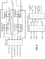
- the communication interface module 14 controls the circuit in Fig. 4 in order to bypass the key switch if in remote mode.
- a conventional wiring harness is modified by adding an inline connector behind the key switch connector as shown in Fig. 4 .
- An auto start control line for the ECM 28 is routed to a 5 pin connector with existing key switch lines.
- Fig. 4 also shows both sides of a new pass through connector with an auto/manual bypass circuit in-between.
- a "stop procedure" is implemented.
- the system monitors ground based vehicle speed and steering angle then applies the brakes based on these two inputs to bring the vehicle to a stop.
- Applications based on a 3D map calibrated to the vehicle may be used to provide feedback of the surrounding terrain.
- controller 12 implements one or more of the following features:
- the communication interface module 14 may provide:
- vehicle 10 (and controller 34) is provided with information regarding the terrain being traversed (via GPS or otherwise, alone or in combination with other sources).
- This information can include the type of terrain, changes in terrain, or otherwise to inform the vehicle 10 about conditions expected to impact operation thereof. Vehicle 10 then uses this information to impact the operation of the vehicle.
- vehicle 10 is determined to be travelling in a cross-hill direction. Vehicle 10 uses this information to impact the stiffness settings of the electrically adjustable shocks to increase vehicle stability.
- other examples include adjusting shock settings by determining whether an on-road or off-road setting is being traversed.
- the CIM 14 Upon enabling autonomous mode, the CIM 14 sends an authentication request to the remote module 12, block 500.
- the request contains a seed value.
- the seed value is illustratively a 7-byte long key that is generated to approximate a random number.
- Remote module 12 receives the request and calculates a key based on the seed value (a private key) and an algorithm, block 510. Module 12 then sends back a public key value to CIM 14, block 520.
- CIM 14 compares the returned value to a value it calculated internally and therefore expects to match the returned value to indicate an authentic module 12.
- CIM 14 Upon receiving the public key value, CIM 14 determines if the response was received within a defined timing window, block 530. This timing requirement limits the ability of a third party to have unlimited time to attempt any number of responses (i.e. a "brute force" hack attempt). If the public key response was received within the required timing window and the public key matches the expected response, block 540, then the module is authenticated and module 12 is permitted to transmit control signals, block 550.
- CIM 14 locks out module 12 and enters a lockout mode (which either disables the vehicle or returns it to manual user control), block 560.
- CIM 14 then waits for another authentication request from module 12 (which may be the same or different module 12 that provided the failed public key response), block 570. Upon receiving another authentication request, CIM 14 enforces a delay to again reduce the likelihood of success for a brute-force type attack, block 580. If the delay time has not elapsed, CIM 14 again locks out module 12 and then waits for another authentication request, block 590. If the delay time has elapsed, then CIM 14 returns to block 510 to again attempt to authenticate module 12.
- CIM 14 receives an input command from module 12, block 600. Each received message has a checksum and message counter value attached thereto. CIM 14 compares the checksum and counter within the message to what is internally calculated (and therefore expected from the message), blocks 610, 620, 630. If either the counter or checksum do not match, CIM 14 locks out module 12, block 560. If the counter and checksum match, then the received command input is accepted and distributed within vehicle 10 to achieve invocation thereof, block 640.
- a vehicle is provided with a communication network having a plurality of vehicle operation devices coupled thereto, the plurality of vehicle operation devices being capable of operating the vehicle, the plurality of vehicle operation devices including a first subset of devices that operate based upon instructions from a vehicle control unit, the plurality of vehicle operation devices including a second subset of devices that provide input to the vehicle control unit, the input being indicative of operator interaction with one or more of the vehicle devices, block 700.
- An interface to the communication network is provided, block 710. Input is received via the interface from an autonomous vehicle controller, thereby allowing the autonomous vehicle controller to control the first subset of vehicle devices independent of input from the second subset of vehicle devices, block 720.
- Embodiments of the disclosure may be practiced using various types of electrical circuits comprising discrete electronic elements, packaged or integrated electronic chips containing logic gates, a circuit utilizing a microprocessor, or on a single chip containing electronic elements or microprocessors. Embodiments of the disclosure may also be practiced using other technologies capable of performing logical operations such as, for example, AND, OR, and NOT, including but not limited to mechanical, optical, fluidic, and quantum technologies. In addition, aspects of the methods described herein can be practiced within a general purpose computer or in any other circuits or systems.
- Embodiments of the present disclosure are implemented as a computer process (method), a computing system, or as an article of manufacture, such as a computer program product or computer readable media.
- the computer program product may be a computer storage media readable by a computer system and encoding a computer program of instructions for executing a computer process.
- embodiments of the present disclosure may be embodied in hardware and/or in software (including firmware, resident software, micro-code, etc.).
- embodiments of the present disclosure may take the form of a computer program product on a computer-usable or computer-readable storage medium having computer-usable or computer-readable program code embodied in the medium for use by or in connection with an instruction execution system.
- a computer-usable or computer-readable medium includes any medium that includes media capable of containing or storing the program for use by or in connection with the instruction execution system, apparatus, or device.
- Embodiments of the present disclosure are described above with reference to block diagrams and/or operational illustrations of methods, systems, and computer program products according to embodiments of the disclosure.
- the functions/acts noted in the blocks may occur out of the order as shown in any flowchart.
- two blocks shown in succession may in fact be executed substantially concurrently or the blocks may sometimes be executed in the reverse order, depending upon the functionality/acts involved.
- a vehicle including: a communication network having a plurality of vehicle devices coupled thereto; a vehicle control unit coupled to the communication network and able to control a first subset of the plurality of devices via the communication network to effect vehicle operation; the vehicle control unit operable to receive input from a second subset of the vehicle devices via the network and to control the first subset of the plurality of devices responsive to the input received from the second subset of vehicle devices, input from the second subset of vehicle devices being indicative of operator interaction with one or more of the vehicle devices; and a network interface; the network interface operable to couple to an autonomous vehicle controller such that the autonomous vehicle controller is able to effect vehicle operation via the first subset of vehicle devices independent of input from the second subset of vehicle devices.
- the first subset of vehicle devices include one or more of a steering controller; a brake, a transmission shift controller, vehicle speed controller, and a vehicle on/off controller.
- the second subset of vehicle devices include one or more of a brake pedal, a steering device, a shift lever, a shift button, an accelerator pedal, and an on/off mode selector.
- the switch is one of a software switch that is able to change states without physical manipulation and a physical switch operable via physical manipulation.
- vehicle control unit receives input from the second subset of the plurality of devices and receives input from the network interface and determines which input to use to control the first subset of the plurality of devices.
- the second subset of vehicle devices includes a brake actuator and the vehicle control unit determines which input to use based upon which input indicates a greatest actuation of the brake actuator.
- the plurality of vehicle devices include a plurality of sensors
- the control unit operable to receive input from the plurality of sensors to determine one or more operational error states of the vehicle
- the control unit further operable to determine conflicting commands between those received from at least one of the plurality of sensors and first subset of vehicle devices and those received via the network interface, the detection of conflicting commands being used to determine one or more error states, the control unit responding to determining one or more error states by entering a degraded operational mode.
- shut-down mode causes the vehicle to come to a stop when the vehicle is in motion and refuses instructions via the network interface until such time as the authentication protocol is successfully completed.
- a method of providing autonomous vehicle operation including: providing a vehicle with a communication network having a plurality of vehicle operation devices coupled thereto, the plurality of vehicle operation devices being capable of operating the vehicle, the plurality of vehicle operation devices including a first subset of devices that operate based upon instructions from a vehicle control unit, the plurality of vehicle operation devices including a second subset of devices that provide input to the vehicle control unit, the input being indicative of operator interaction with one or more of the vehicle devices; providing an interface to the communication network; and receiving, via the interface, input from an autonomous vehicle controller, thereby allowing the autonomous vehicle controller to control the first subset of vehicle devices independent of input from the second subset of vehicle devices.
- the first subset of vehicle devices include one or more of a steering controller; a brake, a transmission shift controller, vehicle speed controller, and a vehicle on/off controller.
- the second subset of vehicle devices include one or more of a brake pedal, a steering device, a shift lever, a shift button, an accelerator pedal, and an on/off mode selector.
- paragraph [0080] further including reviewing commands received via the network interface for controlling the first subset of vehicle devices, the reviewing including comparing the commands to a set of allowable conditions to block implementation of the commands when doing so would cause the vehicle to assume a non-allowable state.
- the switch is one of a software switch that is able to change states without physical manipulation and a physical switch operable via physical manipulation.
- the plurality of vehicle devices include a plurality of sensors, and further including: receiving input by the control unit from the plurality of sensors and determine one or more operational error states of the vehicle responsive to the input, determining, by the control unit, conflicting commands between those received from at least one of the plurality of sensors and first subset of vehicle devices and those received via the network interface, determining one or more error states responsive to the detection of conflicting commands, and entering a degraded operational mode in response to determining existence of the one or more error states.
- a computer readable media having non-transitory instructions thereon that when interpreted by a processor cause the processor to: provide instructions to a first subset of vehicle devices capable of operating a vehicle, the first subset of device operate based upon instructions from a vehicle control unit, the instructions being provided via a vehicle communication network; receive input, via the communication network, from a second subset of vehicle devices, the input being indicative of operator interaction with one or more of the vehicle devices; and receive, via an interface to the communication network, input from an autonomous vehicle controller, thereby allowing the autonomous vehicle controller to control the first subset of vehicle devices independent of input from the second subset of vehicle devices.
Landscapes
- Engineering & Computer Science (AREA)
- Transportation (AREA)
- Mechanical Engineering (AREA)
- Combustion & Propulsion (AREA)
- Chemical & Material Sciences (AREA)
- Automation & Control Theory (AREA)
- Physics & Mathematics (AREA)
- Aviation & Aerospace Engineering (AREA)
- Radar, Positioning & Navigation (AREA)
- Remote Sensing (AREA)
- General Physics & Mathematics (AREA)
- Signal Processing (AREA)
- Human Computer Interaction (AREA)
- Computer Networks & Wireless Communication (AREA)
- Selective Calling Equipment (AREA)
- Control Of Driving Devices And Active Controlling Of Vehicle (AREA)
- Small-Scale Networks (AREA)
- Harvester Elements (AREA)
- Soil Working Implements (AREA)
- Mobile Radio Communication Systems (AREA)
- Business, Economics & Management (AREA)
- Health & Medical Sciences (AREA)
- Artificial Intelligence (AREA)
- Evolutionary Computation (AREA)
- Game Theory and Decision Science (AREA)
- Medical Informatics (AREA)
Abstract
Description
- The present application is a PCT application that claims priority to
US Provisional Application Serial Number 62/091,946; filed December 15, 2014 - The present disclosure relates to an autonomous ready vehicle. More particularly, the present disclosure relates to a vehicle configured to receive commands from an autonomous controller or remote controller to control vehicle functions.
- In one illustrated embodiment of the present disclosure, a system and method are provided for interfacing an autonomous or remote control drive-by-wire controller with a vehicle's control modules. Vehicle functions including steering, braking, starting, etc. are controllable by wire via a control network. For example, a CAN architecture available from Polaris Industries, Inc. is used as an interface between the remote/autonomous controller and the vehicle's control modules in an illustrated embodiment of the present disclosure. A CAN module interface illustratively provides communication between a vehicle control system and a supervisory, remote, autonomous, or drive-by-wire controller. The interface permits the supervisory control to control vehicle operation within pre-determined bounds and using control algorithms.
- In another embodiment, a vehicle is provided including a communication network having a plurality of vehicle devices coupled thereto; a vehicle control unit coupled to the communication network and able to control a first subset of the plurality of devices via the communication network to effect vehicle operation; the vehicle control unit operable to receive input from a second subset of the vehicle devices via the network and to control the first subset of the plurality of devices responsive to the input received from the second subset of vehicle devices, input from the second subset of vehicle devices being indicative of operator interaction with one or more of the vehicle devices; and a network interface; the network interface operable to couple to an autonomous vehicle controller such that the autonomous vehicle controller is able to effect vehicle operation via the first subset of vehicle devices independent of input from the second subset of vehicle devices.
- According to another embodiment of the present disclosure, a method of providing autonomous vehicle operation is provided including: providing a vehicle with a communication network having a plurality of vehicle operation devices coupled thereto, the plurality of vehicle operation devices being capable of operating the vehicle, the plurality of vehicle operation devices including a first subset of devices that operate based upon instructions from a vehicle control unit, the plurality of vehicle operation devices including a second subset of devices that provide input to the vehicle control unit, the input being indicative of operator interaction with one or more of the vehicle devices; and providing an interface to the communication network; receiving, via the interface, input from an autonomous vehicle controller, thereby allowing the autonomous vehicle controller to control the first subset of vehicle devices independent of input from the second subset of vehicle devices.
- According to another embodiment of the present disclosure, a computer readable media having non-transitory instructions thereon is provided that when interpreted by a processor cause the processor to: provide instructions to a first subset of vehicle devices capable of operating a vehicle, the first subset of device operate based upon instructions from a vehicle control unit, the instructions being provided via a vehicle communication network; receive input, via the communication network, from a second subset of vehicle devices, the input being indicative of operator interaction with one or more of the vehicle devices; and receive, via an interface to the communication network, input from an autonomous vehicle controller, thereby allowing the autonomous vehicle controller to control the first subset of vehicle devices independent of input from the second subset of vehicle devices.
- Additional features of the present invention will become apparent to those skilled in the art upon consideration of the following detailed description of illustrative embodiments exemplifying the best mode of carrying out the invention as presently perceived.
- The detailed description of the drawings particularly refers to the accompanying figures in which:
-
Fig. 1 is a block diagram illustrating components of an autonomous ready vehicle of an illustrated embodiment of the present disclosure; -
Fig. 2 is a block diagram illustrating communication between a CAN communication network module of the vehicle and an accessory hardware platform and accessory software; -
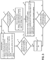
Fig. 3 is a flowchart illustrating steps performed during normal operation in an autonomous or remote control mode and during a lockout mode of operation; -
Fig. 4 is an exemplary wiring harness used to provide by-wire override control of the vehicles ignition; -
Fig. 5 is a flowchart showing illustrative steps performed to authenticate a module sending instructions to the vehicle; and -
Fig. 6 is a flowchart showing illustrative steps that permit autonomous operation of the vehicle. - For the purposes of promoting an understanding of the principles of the present disclosure, reference will now be made to certain illustrated embodiments and drawings. The embodiments disclosed below are not intended to be exhaustive or limit the invention to the precise form disclosed in the following detailed description. Rather, the embodiments are chosen and described so that others skilled in the art may utilize their teachings. It will be understood that no limitation of the scope of the invention is thereby intended. The invention includes any alterations and further modifications in the illustrated devices and described methods and further applications of the principles of the invention which would normally occur to one skilled in the art to which the invention relates.
-
U.S. Patent Application Publication No. 2014/0288763 ;U.S. Patent No. 8,534,397 ;PCT International Publication No. WO 2014/134148 ; andU.S. Patent Application Publication No. 2014/0244110 are all expressly incorporated by reference herein. Features disclosed herein may be used in combination with features disclosed in these patent documents. -
Fig. 1 illustrates components of an autonomousready vehicle 10 of the present disclosure.Vehicle 10 is configured to be controlled by an autonomous orremote controller 12. Thecontroller 12 may be an autonomous controller for controlling thevehicle 10 without any human interaction. Thecontroller 12 may also be a remote controller where an operator uses an input device such as pedals, a joystick, a computer, or other controller to guide thevehicle 10. Functions of thecontroller 12 also include obstacle avoidance. Thecontroller 12 sends specific commands to thevehicle 10 to control movement of the vehicle.Controller 12 also receives feedback from thevehicle 10. Communication with thecontroller 12 is provided through a gateway interface module or communication interface module (CIM) 14 on thevehicle 10. In an illustrated embodiment, the communication interface module is a Controller Area Network (CAN) module. CIM 14 packages information for transport between components. - A
mode switch 16 coupled tomodule 14 permits a user to select between a manual operation mode and the autonomous or remote control mode. In the manual mode, thevehicle 10 is operated by a driver in a normal manner (via operator action on vehicle devices such as a steering device, (such as handles, wheel, joystick), a brake pedal, a gear shift, an accelerator pedal, and an ignition switch (or a sensor that detects operation of any of the foregoing) that respectively cause operation of other vehicle devices, such as a steering device (such as a steering tie arm), a brake actuator, an transmission shifter controller, a throttle, and an ignition relay (generally any vehicle device or actuators for operating such devices). Overall, it should be appreciated that for any operational input device, embodiments are envisioned that utilize physical connections and embodiments are envisioned where sensors are placed on input devices and operation of the devices is communicated via electrical signals. Likewise, embodiments are envisioned where physical connections are used to drive action in actuators and embodiments are envisioned where actuators receive electrical signals that instruct their operation. - In one embodiment, the
mode switch 16 is a physical switch. In other embodiments, themode switch 16 is actuated in software using one of a manned and autonomous or remote user input. Thecommunication interface module 14 controls a system on/offfunction 18 and anignition interrupt function 20. Thecommunication interface module 14 also communicates with adisplay 22 within thevehicle 10. Thedisplay 22 is preferably a high resolution color display. Thedisplay 22 may also be provided by a vehicle gauge display. -
Communication interface module 14 further communicates with an electronicpower steering control 24. Thepower steering control 24 controls a steering position function 26 for guiding thevehicle 10. -
Communication interface module 14 further communicates with an engine control module (ECM) 28. TheECM 28 controls and responds to apedal position function 30.ECM 28 further controls an engine start/stop function 32. Thepedal position function 30 receives instruction from thenetwork interface module 14 whether to accept actual position of the foot pedal or an acceleration command received fromcontroller 12 for controlling the vehicle throttle position. For example, in manual mode thepedal position function 30 takes the physical response from the pedal for throttle application, whereas in autonomous or remote mode thecontroller 12 provides a percentage of throttle that is to be applied in the same manner as the physical application of the throttle. -
Communication interface module 14 further communicates with avehicle control module 34. Thevehicle control module 34 controls atransmission position function 36, abrake position function 38, and a parkingbrake position function 40. Shifting of the vehicle is controlled by a driver during manual mode or by signals received from thecontroller 12 through communication interface module (CIM) 14 in the autonomous or remote control mode. Thevehicle control module 34 also provides vehicle status and sensor information throughcommunication interface module 14 back to thecontroller 12. The vehicle status and sensor information includes, for example, vehicle speed, steering angle, requested speeds, requested steering angles, brake status, fuel level, accelerometer data, brake sensors, throttle position sensors, wheel speed sensors, gear selection sensors, temperature sensors, pressure sensors, emissions levels, trouble codes, error messages, or the like. Thebrake position function 38 is illustratively implemented using an i-Booster intelligent brake control available from Bosch. - Furthermore, in the event of interaction or conflicting messages between the
ECM 28pedal position function 30 andVCM 34brake position function 38 theCIM 14 will filter the appropriate communication messages to pass to theexternal controller 12, thus avoiding interaction issues regarding the input or pedal positions. - The
vehicle control module 34 controls thetransmission position function 36 by detecting a request to shift gears and then providing a shifting signal when conditions are right. Brake position function receives inputs from a pedal position detector and brake commands received over thecommunication interface module 14 to apply thevehicle brakes 38 or theparking brake 40. - Autonomous or
remote controller 12 may also control suspension components through thecommunication interface module 14. Vehicle sensors outputs are received and processed bycontroller 12 and signals are then sent fromcontroller 12 throughcommunication interface module 14 to control adjustable springs or adjustable shocks the vehicle suspension. See, for example,U.S. Patent Application Publication No. 2014/0125018 andU.S. Application Serial No. 14/507,355, filed on October 6, 2014 -
Fig. 2 illustrates an exemplaryaccessory integration device 50 having anaccessory CAN port 52 which communicates through aCAN bus 54 to anaccessory hardware platform 56 of thevehicle 10. Specifically, theCAN bus 54 communicates with ahardware CAN transceiver 58.Transceiver 58 communicates withhardware platform firmware 62 ofaccessory software 60. Thehardware platform firmware 62 communicates with CAN accessory application programming interface (API)software 64. TheAPI software 64 communicates with thirdparty application software 66. - The CAN
accessory API software 64 includes a compiled code library. The library provides an interface between a proprietary CAN network and an application programmer's application code. This allows a third party accessory creator to access specific and limited information on the CAN network, therefore enabling the creation of smart accessories, without access to proprietary information of the CAN network, and without the ability to interfere with vehicle communications. Further, this interface does not allow for compromising the vehicles intended operation or network security. - In one embodiment, the compiled code library includes a set of proprietary, secure, and predefined function calls. The function calls include items such as getEngineRPM( ), getVehicleSpeed( ), or getEngineTemperature( ), for example. The third party application programmer may use these function calls to bring the accessible vehicle information into their application code.
- In one example, the code library may be compatible with large open source electronics platforms. In addition to the software library, a quick start custom accessory includes a durable housing and hardware peripherals that the third party developer may use. The peripherals include, for example, an LED bar and a basic LCD display, etc.
- The present disclosure permits any third party to create software applications for use with the vehicle without interfering with the other functionality of the vehicle. Therefore, third parties can develop smart accessories for use with the vehicle. This enables vehicle users to drive innovation in vehicle accessories.
- In one embodiment, when conflicts arise between individual or multiple manual inputs and input instructions received from the autonomous or
remote controller 12 when thevehicle 10 is in the autonomous or remote control mode, the vehicle may respond with a manual override of autonomous control and theCIM 14 may continue to watch the remote input messages without executing the instructions, while continuing to send CAN messages. - In another embodiment, a user is detected in the vehicle, i.e, via an input torque sensed on the steering wheel, therefore allowing manual operation to override specific or all functions of autonomy.
- Another embodiment includes autonomous or
remote controller 12 override of manual control inputs to the vehicle. For example, messages may be detected from thecontroller 12 allowing for autonomous control to override specific or all functions of manned mode operation. - Some vehicles implement a switch to transition from autonomous or remote mode to manned mode. In some examples, the switch position will override the conflicting messages. For example, if the switch is in autonomous mode, and messages are received from the vehicle pedals, the vehicle will continue to operate in autonomous mode.
- In some instances inputs may comprise manned and autonomy or remote messages that are conflicting or occur simultaneously. For example, if commands are sensed for brake application and throttle application, the
CIM 14 may be calibrated so that the brake application takes precedence. Furthermore, profiles may determine whether the pedal positions were intended actions. If the actions were unintended the vehicle may enter a lockout mode. Otherwise, the responses of the vehicle controls may be calibrated to pre-selected limits. - In another instance, the vehicle's response may include a blended application of at least one of the manned and autonomous or remote inputs. For example, the
CIM 14 may receive messages for throttle application and brake application. A blended response may reduce the throttle to a calibrated level low enough such that the vehicle brakes will overcome the throttle application to the engine. In other situations, alternative calibrations may be desired. These calibrations comprise profiles that pre-select which vehicle features have priority in the event of conflicting messages - An exemplary vehicle system response of conflicting individual or multiple manual inputs and individual or multiple input instructions received from autonomous or
remote controller 12 when thevehicle 10 is in the autonomous or remote control mode, may be as follows: - Brakes: The
vehicle 10 has both mechanical and electrical brake controls. If conflicts occur between the brake pedal input and the brake request command from thecontroller 12, an override causes the strongest braking request (manned or autonomous/remote) to be implemented. Therefore, an occupant in the vehicle may use the brakes to override remote commands to stop thevehicle 10. - Steering: the steering will not respond to manual input.
- Transmission: the transmission will not respond to manual input.
- Engine: the accelerator pedal will be non-responsive to manual input.
- A lockout function of the present disclosure is implemented in a
vehicle 10 which supports both manned and autonomous or remote modes. In manned mode, the vehicle operates normally, receiving inputs from a driver through pedals, a steering wheel, and a shift lever. In remote mode, thevehicle 10 operates by receiving commends from anexternal controller 12 which communicates through a gatewaycommunication interface module 14 which conditions and translates the commands onto the vehicle's CAN network. The lockout function permits only approved third parties to send commands via the vehicle gateway in remote control or autonomous mode. Thevehicle 10 behaves in a known way in the event of the loss of or corruption of communication between thevehicle gateway 14 and theexternal controller 12. - The lockout function is illustratively part of the software which allows a third party to communicate with and drive a vehicle via
controller 12 andinterface module 14. In lockout mode the vehicle operations may comprise coming to a controlled stop, shifting into park, shutting off the engine, locking the steering column/brakes/clutch, shutting off the display/suspending communications, shut off power to the vehicle, inhibit starting of the vehicle. In order to insure only approved third parties are accessing thegateway module 14, the third party's external controller must successfully complete an authentication sequence. In an illustrated embodiment, authentication is based on a J1939 seed key exchange. It is understood that other authentication techniques may also be used. Another embodiment authentication protocol is described below with respect toFig. 5 . - In order to insure only approved third parties are accessing the
gateway module 12 in remote mode the third party'sexternal controller 12 must successfully complete an authentication sequence. In one illustrated example, an authentication sequence is based on the J1939 or other seed key exchange. If an authentication sequence is not initiated and completed successfully at least once every five minutes, for example, then the vehicle enters lockout mode. Additionally, if the integrity of the communication, which may be ensured using checksums, message counters, or other communication errors, in any message coming from the external module to the vehicle gateway is compromised the vehicle enters the lockout mode. - The
gateway control module 14 executes lockout mode by ignoring any incoming CAN message from theexternal controller 12. Thenmodule 14 sends a throttle command of zero over the vehicles internal CAN network and begins to command breaks to stop thevehicle 10. The braking force used is determined by a calibratable map which is dependent on vehicle speed and steering angle. Once the vehicle has stopped moving the transmission is commanded to shift into park and the engine is turned off. Thegateway module 14 ignores incoming messages fromexternal controllers 12, keeps the engine off, the transmission in park, and the brakes depressed until lockout mode is exited. - Exiting the lockout mode may occur by reauthentication, reestablishing communication, by a manual key cycle, etc. In one embodiment, the lockout mode is exited once the
vehicle 10 has come to a complete controlled stop, the engine is shut off, and the transmission is shifted into park. In another embodiment, the lockout mode may be exited during the shutdown sequence (i.e. before a complete controlled stop has occurred, before the engine is shut off, or before the transmission is shifted into park) if reauthentication or reestablished communication occurs during the shutdown sequence. If the lockout was caused by loss of or corrupt communication, then lockout mode is exited once communication has been reestablished. If lockout mode was caused by a failure to authenticate, lockout mode is exited once an authentication sequence completes successfully. If the conditions to exit lockout mode are satisfied while the vehicle is in the process of stopping, shutting down the engine, and parking, the lockout mode is exited once the vehicle has come to a complete stop, shutdown the engine, and shifted into park. - Further details of the normal operation in the autonomous or remote control mode and the lockout mode are illustrated in
Fig. 3 . During normal operation, as illustrated atblock 70, autonomous orremote controller 12 sends drive requests to the communication interface module orgateway interface module 14. Theinterface module 14 sends vehicle status information tocontroller 12.Module 14 also sends drive commands to vehicle communication nodes (such as CAN, Ethernet, etc.) based on the drive requests received fromcontroller 12 as discussed above. Vehicle nodes send status information to theinterface module 14. - Next, the
communication interface module 14 determines whether the autonomous orremote controller 12 has initiated and successfully completed an authentication, such as, for example, a seed key exchange as illustrated atblock 72. If authentication was successfully completed atblock 72,module 14 resets an authentication timer atblock 74 and continues with normal operation atblock 70. If authentication was not successfully completed atblock 72,module 14 determines whether a predetermined period of time, such as 5 minutes, has elapsed since the last successful authentication, as illustrated atblock 76. If the predetermined amount of time has not elapsed atblock 76, normal operation continues atblock 70. If the predetermined amount of time has elapsed atblock 76,module 14 enters a lockout mode atblock 78. -
Module 14 sends drive commands to the vehicle modes to bring the vehicle to a lockout state in a controlled manner as illustrated atblock 78.Module 14 controls braking of the vehicle based upon speed and steering angle of the vehicle to bring the vehicle to a controlled stop.Engine control module 28 then shuts off the engine function atblock 32. In the lockout mode,controller 12 may continue sending drive requests to thecommunication interface module 14. Theinterface module 14 continues to send vehicle status information to thecontroller 12.Interface module 14 sends drive commands to the vehicle nodes in order to maintain lockout of the vehicle. The vehicle nodes send status information back to theinterface module 14. - In another illustrated embodiment, communications form
controller 12 to thevehicle CIM 14 still occurs regardless of the vehicle being in lockout mode. After a predetermined number of failed authentication attempts or a failure in communication, theCIM 14 stops executing commands to the vehicle.Vehicle CIM 14 will still be receive communications fromcontroller 12, but will no longer send communications tocontroller 12. - In yet another illustrated embodiment, when the
vehicle 10 enters lockout mode, the entire vehicle communication network is still functional while the external communication network betweencontroller 12 andCIM 14 is shut down. - In still another illustrated embodiment, active control is provided for individual vehicle nodes of the vehicle communications network. Lockout authentication is applied between any two vehicle nodes or vehicle communications networks to implement lockout functionality. This technique is also be used to prevent an unauthorized vehicle node from being added to the CAN network.
- Next, the
interface module 14 determines whether thecontroller 12 has initiated and successfully completed an authentication, such as by a seed key exchange, as illustrated atblock 82. If not,interface module 14 maintains the lockout mode atblock 80. If the authentication was successful atblock 82,interface module 14 resets the authentication timer atblock 74 and resumes normal operation in which the vehicle is again controlled by the autonomous orremote controller 12. - When the
vehicle 10 is in autonomous or remote control mode, communications failures may occur. In the event of a communications failure, including problems with a message counter and checksum as well as if any J1939 defined "error" messages, thecommunication interface module 14 enter the lockout mode discussed above. If the remote module commands the brakes at greater than 0% and the throttle at greater than 0%, thecommunication interface module 14 obeys the brake command, ignores the throttle command, and broadcasts a diagnostic trouble code over the external CAN network. The following are exemplary actions taken by thecommunication interface module 14 in the event a J1939 "not available" message is received for each subsystem controlled in remote mode. In one example: - Brakes: brake command interpreted as 0%
- Steering: steering angle maintained at last valid requested angle
- Transmission: requested gear maintained at last valid requested gear
- Engine: pedal command interpreted as 0%, engine on/off command interpreted as engine off
- In one illustrated example, if the
CIM 14 receives a brake command and the data says the command is not available, theCIM 14 determines that the command is invalid and waits to see if it receives another message. Limit the number of messages, before a lockout or alternative operation takes place. If multiple input commands (brakes, steering, etc.) are not valid, this could signal a problem and theCIM 14 enters lockout mode to stop these commands from continuing. TheCIM 14 may enable options for any pedal commands, any steering commands, pre-set "limp-home" commands, etc. If problems occur with check sum or data errors, then theCIM 14 uses use last valid commands, however, if the conditions are still not valid vehicle will eventually enter a lockout mode or limp home/degrade mode condition. - In another embodiment, the system permits remote mode selection and vehicle power up remotely. The
communication interface module 14 has a low power mode which wakes when a CAN message is received fromcontroller 12. The mode selection is controlled by a CAN message from the remote controller 12 (if not present default to manual mode). Once woken up, thecommunication interface module 14 controls the circuit inFig. 4 in order to bypass the key switch if in remote mode. A conventional wiring harness is modified by adding an inline connector behind the key switch connector as shown inFig. 4 . An auto start control line for theECM 28 is routed to a 5 pin connector with existing key switch lines.Fig. 4 also shows both sides of a new pass through connector with an auto/manual bypass circuit in-between. - If communication is lost in autonomous or remote control mode while the
vehicle 10 is in motion, a "stop procedure" is implemented. The system monitors ground based vehicle speed and steering angle then applies the brakes based on these two inputs to bring the vehicle to a stop. Applications based on a 3D map calibrated to the vehicle (speed, steering angle and brakes percentage) may be used to provide feedback of the surrounding terrain. - In illustrative embodiments, the
controller 12 implements one or more of the following features: - Vehicle supervisory control to the level of emulating a human driver
- Sensory fusion
- Navigation by GPS corrected inertial navigation or other system capable of required precision in determining position
- Localization
- Lane detection and lane departure
- Extensive terrain and obstacle detection, avoidance and database characterization using real-time or near real-time detection, pre-recorded maps and lane structures, trips planned and tracked, collision avoidance system (LIDAR, Video, sensors), and adaptive cruise control.
- In the absence of communications from a
controller 12, the vehicle has the ability to operate in a full autonomous mode. - The
communication interface module 14 may provide: - Run/Auto Start, Speed /Acceleration Control, Steering, Braking, Gear select, and other chassis functions such as lighting
- Yaw rate models vs. steering command are used at the vehicle control level
- Command modes include target condition and rate with standard and maximum rate of change profiles
- Remote dashboard messages.
- Creating drive profiles from vehicle sensors
- Black out mode
- Infrared (IR) mode
- Automating driveline control, by executing drive modes including 2 wheel drive, 4 wheel drive and turf mode, etc.
- Status messages sent over the CAN include controller conflicting commands, vehicle health data, and state and conditions of vehicle lockout mode.
- Still further, embodiments are envisioned where the vehicle 10 (and controller 34) is provided with information regarding the terrain being traversed (via GPS or otherwise, alone or in combination with other sources). This information can include the type of terrain, changes in terrain, or otherwise to inform the
vehicle 10 about conditions expected to impact operation thereof.Vehicle 10 then uses this information to impact the operation of the vehicle. In one example,vehicle 10 is determined to be travelling in a cross-hill direction.Vehicle 10 uses this information to impact the stiffness settings of the electrically adjustable shocks to increase vehicle stability. Similarly, other examples include adjusting shock settings by determining whether an on-road or off-road setting is being traversed. - With reference to
Fig. 5 , another embodiment authentication protocol is described to ensure only authorized entities are able to access the CAN network to direct operation of the vehicle. Upon enabling autonomous mode, theCIM 14 sends an authentication request to theremote module 12, block 500. The request contains a seed value. The seed value is illustratively a 7-byte long key that is generated to approximate a random number.Remote module 12 receives the request and calculates a key based on the seed value (a private key) and an algorithm, block 510.Module 12 then sends back a public key value toCIM 14, block 520.CIM 14 then compares the returned value to a value it calculated internally and therefore expects to match the returned value to indicate anauthentic module 12. Upon receiving the public key value,CIM 14 determines if the response was received within a defined timing window, block 530. This timing requirement limits the ability of a third party to have unlimited time to attempt any number of responses (i.e. a "brute force" hack attempt). If the public key response was received within the required timing window and the public key matches the expected response, block 540, then the module is authenticated andmodule 12 is permitted to transmit control signals, block 550. - If the public key received within the timing window does not match or if the public key response was received outside of the required window,
CIM 14 locks outmodule 12 and enters a lockout mode (which either disables the vehicle or returns it to manual user control), block 560. -
CIM 14 then waits for another authentication request from module 12 (which may be the same ordifferent module 12 that provided the failed public key response), block 570. Upon receiving another authentication request,CIM 14 enforces a delay to again reduce the likelihood of success for a brute-force type attack, block 580. If the delay time has not elapsed,CIM 14 again locks outmodule 12 and then waits for another authentication request, block 590. If the delay time has elapsed, thenCIM 14 returns to block 510 to again attempt to authenticatemodule 12. - As noted, once a
module 12 is authenticated, it is permitted to transmit commands toCIM module 14 for instructing operation ofvehicle 10. As part of this,CIM 14 receives an input command frommodule 12, block 600. Each received message has a checksum and message counter value attached thereto.CIM 14 compares the checksum and counter within the message to what is internally calculated (and therefore expected from the message), blocks 610, 620, 630. If either the counter or checksum do not match,CIM 14 locks outmodule 12, block 560. If the counter and checksum match, then the received command input is accepted and distributed withinvehicle 10 to achieve invocation thereof, block 640. - Overall, with reference to
Fig. 6 , it should be appreciated that a method allowing ready connection of a vehicle with an autonomous controller disclosed. A vehicle is provided with a communication network having a plurality of vehicle operation devices coupled thereto, the plurality of vehicle operation devices being capable of operating the vehicle, the plurality of vehicle operation devices including a first subset of devices that operate based upon instructions from a vehicle control unit, the plurality of vehicle operation devices including a second subset of devices that provide input to the vehicle control unit, the input being indicative of operator interaction with one or more of the vehicle devices, block 700. An interface to the communication network is provided, block 710. Input is received via the interface from an autonomous vehicle controller, thereby allowing the autonomous vehicle controller to control the first subset of vehicle devices independent of input from the second subset of vehicle devices, block 720. - The logical operations of the various embodiments of the disclosure described herein are implemented as: (1) a sequence of computer implemented steps, operations, or procedures running on a programmable circuit within a computer, and/or (2) a sequence of computer implemented steps, operations, or procedures running on a programmable circuit within a directory system, database, or compiler.
- Embodiments of the disclosure may be practiced using various types of electrical circuits comprising discrete electronic elements, packaged or integrated electronic chips containing logic gates, a circuit utilizing a microprocessor, or on a single chip containing electronic elements or microprocessors. Embodiments of the disclosure may also be practiced using other technologies capable of performing logical operations such as, for example, AND, OR, and NOT, including but not limited to mechanical, optical, fluidic, and quantum technologies. In addition, aspects of the methods described herein can be practiced within a general purpose computer or in any other circuits or systems.
- Embodiments of the present disclosure are implemented as a computer process (method), a computing system, or as an article of manufacture, such as a computer program product or computer readable media. The computer program product may be a computer storage media readable by a computer system and encoding a computer program of instructions for executing a computer process. Accordingly, embodiments of the present disclosure may be embodied in hardware and/or in software (including firmware, resident software, micro-code, etc.). In other words, embodiments of the present disclosure may take the form of a computer program product on a computer-usable or computer-readable storage medium having computer-usable or computer-readable program code embodied in the medium for use by or in connection with an instruction execution system. A computer-usable or computer-readable medium includes any medium that includes media capable of containing or storing the program for use by or in connection with the instruction execution system, apparatus, or device.
- Embodiments of the present disclosure, for example, are described above with reference to block diagrams and/or operational illustrations of methods, systems, and computer program products according to embodiments of the disclosure. The functions/acts noted in the blocks may occur out of the order as shown in any flowchart. For example, two blocks shown in succession may in fact be executed substantially concurrently or the blocks may sometimes be executed in the reverse order, depending upon the functionality/acts involved.
- Various aspects of embodiments of the present invention disclosed herein are described in paragraphs [0066] to [0093] here below:
- A vehicle including: a communication network having a plurality of vehicle devices coupled thereto; a vehicle control unit coupled to the communication network and able to control a first subset of the plurality of devices via the communication network to effect vehicle operation; the vehicle control unit operable to receive input from a second subset of the vehicle devices via the network and to control the first subset of the plurality of devices responsive to the input received from the second subset of vehicle devices, input from the second subset of vehicle devices being indicative of operator interaction with one or more of the vehicle devices; and a network interface; the network interface operable to couple to an autonomous vehicle controller such that the autonomous vehicle controller is able to effect vehicle operation via the first subset of vehicle devices independent of input from the second subset of vehicle devices.
- The vehicle of paragraph [0067], wherein the first subset of vehicle devices include one or more of a steering controller; a brake, a transmission shift controller, vehicle speed controller, and a vehicle on/off controller.
- The vehicle of paragraph [0067], wherein the second subset of vehicle devices include one or more of a brake pedal, a steering device, a shift lever, a shift button, an accelerator pedal, and an on/off mode selector.
- The vehicle of paragraph [0067], further including instructions thereon that when interpreted by a processor cause the processor to review commands received via the network interface for controlling the first subset of vehicle devices, the review comparing the commands to a set of allowable conditions to block implementation of the commands when doing so would cause the vehicle to assume a non-allowable state.
- The vehicle of paragraph [0067], further including a mode switch, the mode switch having a first state in which the first subset of vehicle devices is controlled responsive to the second subset of vehicle devices, the mode switch having a second state in which the first subset of vehicle devices is controlled responsive to commands received via the network interface.
- The vehicle of paragraph [0071], wherein the switch is one of a software switch that is able to change states without physical manipulation and a physical switch operable via physical manipulation.
- The vehicle of paragraph [0067], wherein the vehicle control unit receives input from the second subset of the plurality of devices and receives input from the network interface and determines which input to use to control the first subset of the plurality of devices.
- The vehicle of paragraph [0073], wherein the vehicle control unit determines which input to use responsive to determining a state of a mode switch.
- The vehicle of paragraph [0073], wherein the second subset of vehicle devices includes a brake actuator and the vehicle control unit determines which input to use based upon which input indicates a greatest actuation of the brake actuator.
- The vehicle of paragraph [0067], wherein the plurality of vehicle devices include a plurality of sensors, the control unit operable to receive input from the plurality of sensors to determine one or more operational error states of the vehicle, the control unit further operable to determine conflicting commands between those received from at least one of the plurality of sensors and first subset of vehicle devices and those received via the network interface, the detection of conflicting commands being used to determine one or more error states, the control unit responding to determining one or more error states by entering a degraded operational mode.
- The vehicle of paragraph [0067], further including instructions thereon that, when interpreted by a processor, invoke an authentication protocol to determine whether commands received via the network interface are being sent from an authorized source.
- The vehicle of paragraph [0077], wherein upon a determination that commands received via the network interface are not from an authorized source, the vehicle controller instructs operation of the vehicle as one of operation as instructed via the second subset of vehicle devices and operation via a shut-down mode.
- The vehicle of paragraph [0078], wherein the shut-down mode causes the vehicle to come to a stop when the vehicle is in motion and refuses instructions via the network interface until such time as the authentication protocol is successfully completed.
- A method of providing autonomous vehicle operation including: providing a vehicle with a communication network having a plurality of vehicle operation devices coupled thereto, the plurality of vehicle operation devices being capable of operating the vehicle, the plurality of vehicle operation devices including a first subset of devices that operate based upon instructions from a vehicle control unit, the plurality of vehicle operation devices including a second subset of devices that provide input to the vehicle control unit, the input being indicative of operator interaction with one or more of the vehicle devices; providing an interface to the communication network; and receiving, via the interface, input from an autonomous vehicle controller, thereby allowing the autonomous vehicle controller to control the first subset of vehicle devices independent of input from the second subset of vehicle devices.
- The method of paragraph [0080], wherein the first subset of vehicle devices include one or more of a steering controller; a brake, a transmission shift controller, vehicle speed controller, and a vehicle on/off controller.
- The method of paragraph [0080], wherein the second subset of vehicle devices include one or more of a brake pedal, a steering device, a shift lever, a shift button, an accelerator pedal, and an on/off mode selector.
- The method of paragraph [0080], further including reviewing commands received via the network interface for controlling the first subset of vehicle devices, the reviewing including comparing the commands to a set of allowable conditions to block implementation of the commands when doing so would cause the vehicle to assume a non-allowable state.
- The method of paragraph [0080], further including detecting a state of a mode switch, the mode switch having a first state in which the first subset of vehicle devices is controlled responsive to the second subset of vehicle devices, the mode switch having a second state in which the first subset of vehicle devices is controlled responsive to commands received via the network interface.
- The method of paragraph [0084], wherein the switch is one of a software switch that is able to change states without physical manipulation and a physical switch operable via physical manipulation.
- The method of paragraph [0080], further including: receiving, by the vehicle control unit, input from the second subset of the plurality of devices; receiving, by the vehicle control unit, input from the network interface; and determining which input to use to control the first subset of the plurality of devices.
- The method of paragraph [0086], wherein the determining is performed by the vehicle control unit responsive to determining a state of a mode switch.
- The method of paragraph [0086], wherein the second subset of vehicle devices includes a brake actuator and the vehicle control unit determines which input to use based upon which input indicates a greatest actuation of the brake actuator.
- The method of paragraph [0080], wherein the plurality of vehicle devices include a plurality of sensors, and further including: receiving input by the control unit from the plurality of sensors and determine one or more operational error states of the vehicle responsive to the input, determining, by the control unit, conflicting commands between those received from at least one of the plurality of sensors and first subset of vehicle devices and those received via the network interface, determining one or more error states responsive to the detection of conflicting commands, and entering a degraded operational mode in response to determining existence of the one or more error states.
- The method of paragraph [0080], further including invoking an authentication protocol to determine whether commands received via the network interface are being sent from an authorized source.
- The method of paragraph [0090], further including determining that commands received via the network interface are not from an authorized source, and in response instructing operation of the vehicle as one of operation as instructed via the second subset of vehicle devices and operation via a shut-down mode.
- The method of paragraph [0091], wherein operating via the shut-down mode causes the vehicle to come to a stop when the vehicle is in motion and refuses instructions via the network interface until such time as the authentication protocol is successfully completed.
- A computer readable media having non-transitory instructions thereon that when interpreted by a processor cause the processor to: provide instructions to a first subset of vehicle devices capable of operating a vehicle, the first subset of device operate based upon instructions from a vehicle control unit, the instructions being provided via a vehicle communication network; receive input, via the communication network, from a second subset of vehicle devices, the input being indicative of operator interaction with one or more of the vehicle devices; and receive, via an interface to the communication network, input from an autonomous vehicle controller, thereby allowing the autonomous vehicle controller to control the first subset of vehicle devices independent of input from the second subset of vehicle devices.
Claims (13)
- A vehicle gateway unit including:a gateway communication interface module (14) operable to couple with an autonomous controller (12); the gateway communication interface module (14) providing the sole communication path for the autonomous controller (12) to communicate with a Controller Area Network (CAN);a CAN interface operable to communicate with an engine control module (28) over the CAN;a mode switch (16) coupled to the CAN interface, the mode switch (16) being selectively operable between a manual operation mode and an autonomous control mode;wherein the gateway communication interface module (14) is operable to cause commands received from the autonomous controller (12) to be translated into commands operable with the engine control module (28) in response to determining authentication of the autonomous controller (12) and the mode switch (16) being in the autonomous control mode.
- The vehicle gateway unit of claim 1, wherein the gateway communication interface module is operable to authenticate the autonomous controller (12) via a J1939 seed key exchange.
- The vehicle gateway unit of claim 1, wherein the gateway communication interface module (14) includes an accessory application programming interface.
- The vehicle gateway unit of claim 3, wherein the accessory application programming interface provides an accessory with access to the CAN.
- The vehicle gateway unit of claim 1, wherein the gateway communication interface module (14) selectively engages a lockout mode that refuses instructions from the autonomous controller (12).
- The vehicle gateway unit of claim 1, wherein the gateway communication interface module (14) is further operable to send vehicle data to the autonomous controller (12).
- The vehicle gateway unit of claim 1, wherein the gateway communication interface module (14) requires authentication operations to be performed within a pre-defined timing window.
- A method of operating a vehicle gateway unit including:providing a gateway communication interface module (14) operable to couple with an autonomous controller (12);providing a Controller Area Network (CAN) interface operable to communicate with an engine control module (28) over a CAN;providing, via the gateway communication interface module (14), the sole communication path between the autonomous controller (12) and the CAN interface;providing a mode switch (16) operable to communicate with the CAN interface, the mode switch (16) being selectively operable between a manual operation mode and an autonomous control mode;determining, by the gateway communication interface module (14), authentication of the autonomous controller (12) coupled to the gateway communication interface module (14);determining, by the gateway communication interface module (14), the mode switch (16) is in the autonomous control mode;translating, by the gateway communication interface module (14), authenticated commands received from the autonomous controller (12) via the gateway communication interface module (14) to be operable with the engine control module (28); andproviding, by the gateway communication interface module (14), translated commands to the CAN interface.
- The method of claim 8, wherein authenticating includes performing a J1939 seed key exchange.
- The method of claim 8, further including an accessory application programming interface that provides an accessory with access to the CAN.
- The method of claim 8, further including selectively engaging a lockout mode by the gateway communication interface module (14) that refuses instructions from the autonomous controller (12).
- The method of claim 8, further including sending vehicle data to the autonomous controller (12) via the gateway communication interface module (14).
- The method of claim 8, further including determining whether authentication operations are performed within a pre-defined timing window and engaging a lockout mode when the authentication operations fail to be performed within the pre-defined timing window.
Applications Claiming Priority (3)
| Application Number | Priority Date | Filing Date | Title |
|---|---|---|---|
| US201462091946P | 2014-12-15 | 2014-12-15 | |
| EP15820394.3A EP3234712A1 (en) | 2014-12-15 | 2015-12-14 | Autonomous ready vehicle |
| PCT/US2015/065586 WO2016100219A1 (en) | 2014-12-15 | 2015-12-14 | Autonomous ready vehicle |
Related Parent Applications (1)
| Application Number | Title | Priority Date | Filing Date |
|---|---|---|---|
| EP15820394.3A Division EP3234712A1 (en) | 2014-12-15 | 2015-12-14 | Autonomous ready vehicle |
Publications (1)
| Publication Number | Publication Date |
|---|---|
| EP3521961A1 true EP3521961A1 (en) | 2019-08-07 |
Family
ID=55070172
Family Applications (2)
| Application Number | Title | Priority Date | Filing Date |
|---|---|---|---|
| EP15820394.3A Withdrawn EP3234712A1 (en) | 2014-12-15 | 2015-12-14 | Autonomous ready vehicle |
| EP19165018.3A Ceased EP3521961A1 (en) | 2014-12-15 | 2015-12-14 | Autonomous ready vehicle |
Family Applications Before (1)
| Application Number | Title | Priority Date | Filing Date |
|---|---|---|---|
| EP15820394.3A Withdrawn EP3234712A1 (en) | 2014-12-15 | 2015-12-14 | Autonomous ready vehicle |
Country Status (9)
| Country | Link |
|---|---|
| US (4) | US10160436B2 (en) |
| EP (2) | EP3234712A1 (en) |
| JP (3) | JP2018506461A (en) |
| AU (3) | AU2015362825B2 (en) |
| CA (2) | CA3174624A1 (en) |
| IL (4) | IL305177A (en) |
| MX (1) | MX370811B (en) |
| WO (1) | WO2016100219A1 (en) |
| ZA (1) | ZA202103570B (en) |
Families Citing this family (68)
| Publication number | Priority date | Publication date | Assignee | Title |
|---|---|---|---|---|
| IL305177A (en) | 2014-12-15 | 2023-10-01 | Polaris Inc | Autonomous ready vehicle |
| US10338801B2 (en) * | 2015-04-30 | 2019-07-02 | Cnh Industrial America Llc | Agricultural vehicle calibration via human machine interface |
| US10152336B2 (en) * | 2015-12-26 | 2018-12-11 | Intel Corporation | Technologies for managing sensor conflicts |
| JP6246844B2 (en) * | 2016-02-18 | 2017-12-13 | 本田技研工業株式会社 | Vehicle control system, vehicle control method, and vehicle control program |
| US10787176B2 (en) | 2016-02-19 | 2020-09-29 | A Truly Electric Car Company | Plug-compatible interface between cars and their human and/or computer drivers |
| DE102016005317A1 (en) * | 2016-05-02 | 2017-11-02 | Wabco Gmbh | Method for automated electronic control of a brake system and electronically controllable brake system in a commercial vehicle |
| US11698635B2 (en) | 2016-08-10 | 2023-07-11 | Jaguar Land Rover Limited | Control of an autonomous vehicle |
| US11112805B2 (en) * | 2016-08-15 | 2021-09-07 | Transporation IP Holdings, LLC | Vehicle communication system, control system, and method |
| US10322719B2 (en) * | 2016-09-08 | 2019-06-18 | Ford Global Technologies, Llc | Vehicle repositioning system |
| US9947052B1 (en) | 2016-12-20 | 2018-04-17 | Allstate Insurance Company | Controlling autonomous vehicles to optimize traffic characteristics |
| US10343631B2 (en) * | 2016-12-28 | 2019-07-09 | Uber Technologies, Inc. | Decreasing autonomous vehicle power consumption |
| US10556675B2 (en) | 2017-01-17 | 2020-02-11 | Goodrich Corporation | System and method for autobraking with course trajectory adjustment |
| GB2588034B (en) * | 2017-01-30 | 2021-07-14 | Jaguar Land Rover Ltd | Controlling movement of a vehicle |
| GB2559172B (en) * | 2017-01-30 | 2021-01-13 | Jaguar Land Rover Ltd | Controlling movement of a vehicle |
| CN108536114A (en) * | 2017-03-01 | 2018-09-14 | 北京图森未来科技有限公司 | A kind of controller of vehicle |
| US10440536B2 (en) * | 2017-05-19 | 2019-10-08 | Waymo Llc | Early boarding of passengers in autonomous vehicles |
| US10103938B1 (en) | 2017-05-24 | 2018-10-16 | GM Global Technology Operations LLC | Vehicle network switch configurations based on driving mode |
| KR102387613B1 (en) * | 2017-06-26 | 2022-04-15 | 엘지전자 주식회사 | Interface system for vehicle |
| US10308242B2 (en) * | 2017-07-01 | 2019-06-04 | TuSimple | System and method for using human driving patterns to detect and correct abnormal driving behaviors of autonomous vehicles |
| US10579788B2 (en) | 2017-08-17 | 2020-03-03 | Waymo Llc | Recognizing assigned passengers for autonomous vehicles |
| US10759466B2 (en) | 2017-10-03 | 2020-09-01 | Ford Global Technologies, Llc | Vehicle component operation |
| US10710602B2 (en) * | 2017-10-06 | 2020-07-14 | Uatc, Llc | Systems and methods for a vehicle controller safety monitor |
| JP6939376B2 (en) | 2017-10-10 | 2021-09-22 | トヨタ自動車株式会社 | Autonomous driving system |
| US11104330B2 (en) * | 2017-11-15 | 2021-08-31 | Autonomous Stuff, LLC | Systems and method for controlling a vehicle |
| US20190187691A1 (en) | 2017-12-18 | 2019-06-20 | Steeringz, Inc. | Safety of autonomous vehicles by remote support request |
| US11130497B2 (en) * | 2017-12-18 | 2021-09-28 | Plusai Limited | Method and system for ensemble vehicle control prediction in autonomous driving vehicles |
| US20190185012A1 (en) | 2017-12-18 | 2019-06-20 | PlusAI Corp | Method and system for personalized motion planning in autonomous driving vehicles |
| US11137757B2 (en) | 2018-03-23 | 2021-10-05 | Ford Global Technologies, Llc | Method and apparatus for selective drive-mode enablement |
| JP7020230B2 (en) * | 2018-03-23 | 2022-02-16 | 株式会社豊田自動織機 | Remote control system for industrial vehicles, industrial vehicles, remote control devices, remote control programs for industrial vehicles, and remote control methods for industrial vehicles |
| JP7069975B2 (en) * | 2018-03-30 | 2022-05-18 | トヨタ自動車株式会社 | Controls, programs for controls, and control methods |
| JP7006453B2 (en) * | 2018-03-30 | 2022-01-24 | トヨタ自動車株式会社 | Controls, programs, and control methods |
| JP6962258B2 (en) * | 2018-03-30 | 2021-11-05 | トヨタ自動車株式会社 | Control devices, programs for control devices, and control methods |
| US10331128B1 (en) | 2018-04-20 | 2019-06-25 | Lyft, Inc. | Control redundancy |
| CN108677834A (en) * | 2018-07-06 | 2018-10-19 | 北京京环装备设计研究院有限公司 | Pure electric vehicle road sweeper vehicle electric-control system |
| US10909866B2 (en) | 2018-07-20 | 2021-02-02 | Cybernet Systems Corp. | Autonomous transportation system and methods |
| KR102646674B1 (en) * | 2018-09-04 | 2024-03-13 | 현대자동차주식회사 | Vehicle and method for controlling the same |
| WO2020101127A1 (en) * | 2018-11-13 | 2020-05-22 | Samsung Electro-Mechanics Co., Ltd. | Driving support system and method |
| IT201800010349A1 (en) * | 2018-11-15 | 2020-05-15 | Faiveley Transport Italia Spa | Electronic brake control system of a railway vehicle |
| US20200262366A1 (en) | 2019-02-14 | 2020-08-20 | Oshkosh Corporation | Integrated operator centric controls |
| US11692375B2 (en) * | 2019-03-14 | 2023-07-04 | Lippert Components Inc. | Consensus building among networked devices for recreational vehicle safety systems |
| US11456880B2 (en) * | 2019-03-25 | 2022-09-27 | Micron Technology, Inc. | Cryptographically secure mechanism for remotely controlling an autonomous vehicle |
| DE102019108095A1 (en) * | 2019-03-28 | 2020-10-01 | Infineon Technologies Ag | Perform a cryptographic operation |
| CN111174805A (en) * | 2019-04-30 | 2020-05-19 | 奥特酷智能科技(南京)有限公司 | Distributed centralized automatic driving system |
| US11352768B2 (en) * | 2019-07-16 | 2022-06-07 | Caterpillar Inc. | Locking out a machine to prohibit movement |
| JP7243512B2 (en) * | 2019-07-29 | 2023-03-22 | トヨタ自動車株式会社 | Remote control system, program and vehicle |
| CN110466495B (en) * | 2019-09-02 | 2024-04-09 | 浙江鸿吉智能控制有限公司 | Intelligent automatic vector driving execution system and control method |
| US10889237B1 (en) * | 2019-10-23 | 2021-01-12 | Tusimple, Inc. | Lighting control for autonomous vehicles |
| IT202000000025A1 (en) * | 2020-01-02 | 2021-07-02 | Alba Robot Srl | DEVICE FOR THE AUTONOMOUS HANDLING OF WHEEL EQUIPMENT AND RELATIVE INSTALLATION METHOD |
| JP7354861B2 (en) * | 2020-01-31 | 2023-10-03 | トヨタ自動車株式会社 | vehicle |
| JP7287299B2 (en) * | 2020-01-31 | 2023-06-06 | トヨタ自動車株式会社 | Vehicle and vehicle control interface |
| JP7459532B2 (en) | 2020-01-31 | 2024-04-02 | トヨタ自動車株式会社 | vehicle |
| JP7306283B2 (en) * | 2020-01-31 | 2023-07-11 | トヨタ自動車株式会社 | vehicle |
| JP7306284B2 (en) | 2020-01-31 | 2023-07-11 | トヨタ自動車株式会社 | Vehicle and vehicle control interface |
| JP7272295B2 (en) * | 2020-01-31 | 2023-05-12 | トヨタ自動車株式会社 | vehicle |
| JP7283406B2 (en) * | 2020-01-31 | 2023-05-30 | トヨタ自動車株式会社 | vehicle |
| JP7255507B2 (en) | 2020-01-31 | 2023-04-11 | トヨタ自動車株式会社 | vehicle |
| US11287806B2 (en) | 2020-02-11 | 2022-03-29 | Uatc, Llc | Vehicle computing system cooling systems |
| US11513517B2 (en) * | 2020-03-30 | 2022-11-29 | Uatc, Llc | System and methods for controlling state transitions using a vehicle controller |
| CN113022540B (en) * | 2020-04-17 | 2022-11-15 | 青岛慧拓智能机器有限公司 | Real-time remote driving system and method for monitoring multiple vehicle states |
| CN111547065B (en) * | 2020-05-07 | 2022-01-11 | 新石器慧通(北京)科技有限公司 | Unmanned vehicle remote controller control method, controller and control system |
| CN112141088A (en) * | 2020-06-24 | 2020-12-29 | 上汽通用五菱汽车股份有限公司 | Parking control method and device, vehicle and readable storage medium |
| CN112099490B (en) * | 2020-08-19 | 2024-04-26 | 北京经纬恒润科技股份有限公司 | Method for remotely driving vehicle and remote driving system |
| CN112061093B (en) * | 2020-09-21 | 2021-07-20 | 中车青岛四方车辆研究所有限公司 | Locomotive braking system for realizing automatic driving and realization method thereof |
| EP4232835A1 (en) * | 2020-10-20 | 2023-08-30 | Polaris Industries Inc. | Vehicle communication and monitoring |
| KR20220108250A (en) * | 2021-01-25 | 2022-08-03 | 현대자동차주식회사 | System for controlling failure of environmental vehicle |
| MX2022008716A (en) * | 2021-07-20 | 2023-01-23 | Polaris Inc | Automatic vehicle control. |
| CN114407908B (en) * | 2022-02-21 | 2024-03-12 | 浙江绿色慧联有限公司 | Remote vehicle control method, system, equipment and medium based on vehicle safety |
| DE102022113333A1 (en) | 2022-05-25 | 2023-11-30 | Zf Cv Systems Global Gmbh | Adaptation device for enabling automated operation of a vehicle through conversion |
Citations (8)
| Publication number | Priority date | Publication date | Assignee | Title |
|---|---|---|---|---|
| CA2314307A1 (en) * | 2000-07-21 | 2002-01-21 | Vansco Electronics Ltd. | Electrical control apparatus for leased equipment |
| EP1598245A2 (en) * | 2004-05-18 | 2005-11-23 | Iveco S.p.A. | Device and method for preventing unauthorized starting of a vehicle |
| US20130212659A1 (en) * | 2012-02-13 | 2013-08-15 | Intertrust Technologies Corporation | Trusted connected vehicle systems and methods |
| US8534397B2 (en) | 2010-06-03 | 2013-09-17 | Polaris Industries Inc. | Electronic throttle control |
| US20140125018A1 (en) | 2012-11-07 | 2014-05-08 | Polaris Industries Inc. | Vehicle having suspension with continuous damping control |
| US20140244110A1 (en) | 2013-02-26 | 2014-08-28 | Polaris Industries Inc. | Recreational vehicle interactive vehicle information, telemetry, mapping, and trip planning |
| WO2014134148A2 (en) | 2013-02-26 | 2014-09-04 | Polaris Industries Inc. | Recreational vehicle interactive telemetry, mapping, and trip planning system |
| US20140288763A1 (en) | 2013-03-25 | 2014-09-25 | Polaris Industries Inc. | Tracked all-terrain vehicle |
Family Cites Families (28)
| Publication number | Priority date | Publication date | Assignee | Title |
|---|---|---|---|---|
| JP2003118550A (en) * | 2001-10-12 | 2003-04-23 | Denso Corp | Vehicle stop control system and vehicle control device |
| JP3767481B2 (en) * | 2001-12-27 | 2006-04-19 | 株式会社デンソー | Interface equipment |
| US7299099B1 (en) * | 2004-02-18 | 2007-11-20 | Divelbiss Corporation | Programmable logic controller contained on a chip |
| JP2006143083A (en) * | 2004-11-22 | 2006-06-08 | Aisin Aw Co Ltd | Theft prevention system of mobile body and navigation device |
| US9043016B2 (en) * | 2005-10-21 | 2015-05-26 | Deere & Company | Versatile robotic control module |
| US8843244B2 (en) * | 2006-10-06 | 2014-09-23 | Irobot Corporation | Autonomous behaviors for a remove vehicle |
| JP2006320033A (en) * | 2006-09-04 | 2006-11-24 | Hitachi Ltd | Control unit and control unit development apparatus |
| DE102007058163A1 (en) * | 2007-09-28 | 2009-04-23 | Continental Automotive Gmbh | Tachograph, toll-on-board unit, indicating instrument and system |
| JP2011070611A (en) * | 2009-09-28 | 2011-04-07 | Kyocera Corp | Electronic apparatus |
| US9081653B2 (en) * | 2011-11-16 | 2015-07-14 | Flextronics Ap, Llc | Duplicated processing in vehicles |
| US20140143839A1 (en) * | 2011-11-16 | 2014-05-22 | Flextronics Ap, Llc. | On board vehicle remote control module |
| US9147336B2 (en) * | 2012-02-29 | 2015-09-29 | Verizon Patent And Licensing Inc. | Method and system for generating emergency notifications based on aggregate event data |
| US8595037B1 (en) * | 2012-05-08 | 2013-11-26 | Elwha Llc | Systems and methods for insurance based on monitored characteristics of an autonomous drive mode selection system |
| US20130304514A1 (en) * | 2012-05-08 | 2013-11-14 | Elwha Llc | Systems and methods for insurance based on monitored characteristics of an autonomous drive mode selection system |
| US9156476B2 (en) * | 2012-10-02 | 2015-10-13 | Trevor O'Neill | System and method for remote control of unmanned vehicles |
| US10025306B2 (en) * | 2012-10-02 | 2018-07-17 | Nathan Bivans | System and method for remote control of unmanned vehicles |
| US9205717B2 (en) | 2012-11-07 | 2015-12-08 | Polaris Industries Inc. | Vehicle having suspension with continuous damping control |
| US8825258B2 (en) * | 2012-11-30 | 2014-09-02 | Google Inc. | Engaging and disengaging for autonomous driving |
| US9342074B2 (en) * | 2013-04-05 | 2016-05-17 | Google Inc. | Systems and methods for transitioning control of an autonomous vehicle to a driver |
| EP3126167A1 (en) * | 2014-04-02 | 2017-02-08 | Levant Power Corporation | Active safety suspension system |
| US9426650B2 (en) * | 2014-10-31 | 2016-08-23 | Gogo Llc | Autonomous-mode content delivery and key management |
| US9430944B2 (en) * | 2014-11-12 | 2016-08-30 | GM Global Technology Operations LLC | Method and apparatus for determining traffic safety events using vehicular participative sensing systems |
| IL305177A (en) * | 2014-12-15 | 2023-10-01 | Polaris Inc | Autonomous ready vehicle |
| US20170017734A1 (en) * | 2015-07-15 | 2017-01-19 | Ford Global Technologies, Llc | Crowdsourced Event Reporting and Reconstruction |
| US9829885B2 (en) * | 2015-11-18 | 2017-11-28 | Toyota Motor Engineering & Manufacturing North America, Inc. | Personal storage for shared vehicles |
| US9637965B1 (en) * | 2015-11-18 | 2017-05-02 | Ankit Dilip Kothari | Proactive vehicle doors to prevent accidents |
| WO2018039142A1 (en) * | 2016-08-22 | 2018-03-01 | Rapidsos, Inc. | Predictive analytics for emergency detection and response management |
| US10699305B2 (en) * | 2016-11-21 | 2020-06-30 | Nio Usa, Inc. | Smart refill assistant for electric vehicles |
-
2015
- 2015-12-14 IL IL305177A patent/IL305177A/en unknown
- 2015-12-14 IL IL286020A patent/IL286020B/en unknown
- 2015-12-14 EP EP15820394.3A patent/EP3234712A1/en not_active Withdrawn
- 2015-12-14 WO PCT/US2015/065586 patent/WO2016100219A1/en active Application Filing
- 2015-12-14 CA CA3174624A patent/CA3174624A1/en active Pending
- 2015-12-14 IL IL294250A patent/IL294250B2/en unknown
- 2015-12-14 CA CA2969155A patent/CA2969155C/en active Active
- 2015-12-14 MX MX2017006526A patent/MX370811B/en active IP Right Grant
- 2015-12-14 US US14/968,487 patent/US10160436B2/en active Active
- 2015-12-14 EP EP19165018.3A patent/EP3521961A1/en not_active Ceased
- 2015-12-14 JP JP2017530636A patent/JP2018506461A/en active Pending
- 2015-12-14 AU AU2015362825A patent/AU2015362825B2/en active Active
-
2017
- 2017-05-01 IL IL252060A patent/IL252060B/en unknown
-
2018
- 2018-12-12 US US16/218,025 patent/US10640101B2/en active Active
-
2020
- 2020-04-22 US US16/855,603 patent/US11400914B2/en active Active
- 2020-06-30 AU AU2020204368A patent/AU2020204368B2/en active Active
- 2020-12-07 JP JP2020202545A patent/JP7312158B2/en active Active
-
2021
- 2021-05-26 ZA ZA2021/03570A patent/ZA202103570B/en unknown
-
2022
- 2022-04-27 AU AU2022202756A patent/AU2022202756B2/en active Active
- 2022-07-07 US US17/859,300 patent/US20220348183A1/en active Pending
-
2023
- 2023-07-07 JP JP2023112463A patent/JP2023129457A/en active Pending
Patent Citations (8)
| Publication number | Priority date | Publication date | Assignee | Title |
|---|---|---|---|---|
| CA2314307A1 (en) * | 2000-07-21 | 2002-01-21 | Vansco Electronics Ltd. | Electrical control apparatus for leased equipment |
| EP1598245A2 (en) * | 2004-05-18 | 2005-11-23 | Iveco S.p.A. | Device and method for preventing unauthorized starting of a vehicle |
| US8534397B2 (en) | 2010-06-03 | 2013-09-17 | Polaris Industries Inc. | Electronic throttle control |
| US20130212659A1 (en) * | 2012-02-13 | 2013-08-15 | Intertrust Technologies Corporation | Trusted connected vehicle systems and methods |
| US20140125018A1 (en) | 2012-11-07 | 2014-05-08 | Polaris Industries Inc. | Vehicle having suspension with continuous damping control |
| US20140244110A1 (en) | 2013-02-26 | 2014-08-28 | Polaris Industries Inc. | Recreational vehicle interactive vehicle information, telemetry, mapping, and trip planning |
| WO2014134148A2 (en) | 2013-02-26 | 2014-09-04 | Polaris Industries Inc. | Recreational vehicle interactive telemetry, mapping, and trip planning system |
| US20140288763A1 (en) | 2013-03-25 | 2014-09-25 | Polaris Industries Inc. | Tracked all-terrain vehicle |
Non-Patent Citations (1)
| Title |
|---|
| WEI JUNQING ET AL: "Towards a viable autonomous driving research platform", 2013 IEEE INTELLIGENT VEHICLES SYMPOSIUM (IV), IEEE, 23 June 2013 (2013-06-23), pages 763 - 770, XP032502021, ISSN: 1931-0587, [retrieved on 20131010], DOI: 10.1109/IVS.2013.6629559 * |
Also Published As
| Publication number | Publication date |
|---|---|
| IL294250B2 (en) | 2024-01-01 |
| JP2018506461A (en) | 2018-03-08 |
| JP2021059328A (en) | 2021-04-15 |
| IL286020B (en) | 2022-07-01 |
| IL252060B (en) | 2021-09-30 |
| US10640101B2 (en) | 2020-05-05 |
| EP3234712A1 (en) | 2017-10-25 |
| WO2016100219A1 (en) | 2016-06-23 |
| JP2023129457A (en) | 2023-09-14 |
| AU2022202756A1 (en) | 2022-05-19 |
| IL294250B1 (en) | 2023-09-01 |
| US20160167653A1 (en) | 2016-06-16 |
| JP7312158B2 (en) | 2023-07-20 |
| CA3174624A1 (en) | 2016-06-23 |
| ZA202103570B (en) | 2022-05-25 |
| CA2969155C (en) | 2023-10-17 |
| AU2022202756B2 (en) | 2024-03-14 |
| AU2020204368B2 (en) | 2022-01-27 |
| IL286020A (en) | 2021-10-31 |
| AU2015362825B2 (en) | 2020-04-02 |
| IL294250A (en) | 2022-08-01 |
| CA2969155A1 (en) | 2016-06-23 |
| US11400914B2 (en) | 2022-08-02 |
| US20200298818A1 (en) | 2020-09-24 |
| US10160436B2 (en) | 2018-12-25 |
| MX370811B (en) | 2020-01-08 |
| MX2017006526A (en) | 2017-08-09 |
| AU2020204368A1 (en) | 2020-07-23 |
| US20220348183A1 (en) | 2022-11-03 |
| US20190118792A1 (en) | 2019-04-25 |
| IL305177A (en) | 2023-10-01 |
| IL252060A0 (en) | 2017-07-31 |
| AU2015362825A1 (en) | 2017-07-06 |
Similar Documents
| Publication | Publication Date | Title |
|---|---|---|
| US11400914B2 (en) | Autonomous ready vehicle | |
| US20230192113A1 (en) | Information processing apparatus | |
| US9616896B1 (en) | System for switching control of an autonomous vehicle | |
| US10585432B2 (en) | Drive-by-wire control system | |
| CN108819944B (en) | Hill start anti-sliding control method and device and electronic equipment | |
| US8855833B2 (en) | Vehicle dynamic control platform between application and controlled object | |
| RU2754284C1 (en) | Control device | |
| US20130304277A1 (en) | Vehicle control system | |
| JP5021163B2 (en) | Method and apparatus for controlling drive sequences, particularly in vehicles | |
| US20240126279A1 (en) | Control system and method | |
| KR20170026267A (en) | Method and device for operating a driving system for a motor vehicle | |
| JP2017105362A (en) | Control system | |
| KR101835783B1 (en) | Power train control unit for vehicle | |
| US20240137763A1 (en) | Control system and method | |
| KR20240021346A (en) | Apparatus for controlling a vehicle and method thereof | |
| CN114523976A (en) | Control system and method for intelligently driving vehicle |
Legal Events
| Date | Code | Title | Description |
|---|---|---|---|
| PUAI | Public reference made under article 153(3) epc to a published international application that has entered the european phase |
Free format text: ORIGINAL CODE: 0009012 |
|
| STAA | Information on the status of an ep patent application or granted ep patent |
Free format text: STATUS: THE APPLICATION HAS BEEN PUBLISHED |
|
| AC | Divisional application: reference to earlier application |
Ref document number: 3234712 Country of ref document: EP Kind code of ref document: P |
|
| AK | Designated contracting states |
Kind code of ref document: A1 Designated state(s): AL AT BE BG CH CY CZ DE DK EE ES FI FR GB GR HR HU IE IS IT LI LT LU LV MC MK MT NL NO PL PT RO RS SE SI SK SM TR |
|
| STAA | Information on the status of an ep patent application or granted ep patent |
Free format text: STATUS: REQUEST FOR EXAMINATION WAS MADE |
|
| STAA | Information on the status of an ep patent application or granted ep patent |
Free format text: STATUS: EXAMINATION IS IN PROGRESS |
|
| 17P | Request for examination filed |
Effective date: 20200204 |
|
| RBV | Designated contracting states (corrected) |
Designated state(s): AL AT BE BG CH CY CZ DE DK EE ES FI FR GB GR HR HU IE IS IT LI LT LU LV MC MK MT NL NO PL PT RO RS SE SI SK SM TR |
|
| 17Q | First examination report despatched |
Effective date: 20200312 |
|
| STAA | Information on the status of an ep patent application or granted ep patent |
Free format text: STATUS: EXAMINATION IS IN PROGRESS |
|
| APBK | Appeal reference recorded |
Free format text: ORIGINAL CODE: EPIDOSNREFNE |
|
| APBN | Date of receipt of notice of appeal recorded |
Free format text: ORIGINAL CODE: EPIDOSNNOA2E |
|
| APBR | Date of receipt of statement of grounds of appeal recorded |
Free format text: ORIGINAL CODE: EPIDOSNNOA3E |
|
| APAF | Appeal reference modified |
Free format text: ORIGINAL CODE: EPIDOSCREFNE |
|
| P01 | Opt-out of the competence of the unified patent court (upc) registered |
Effective date: 20230514 |
|
| APAF | Appeal reference modified |
Free format text: ORIGINAL CODE: EPIDOSCREFNE |
|
| APBT | Appeal procedure closed |
Free format text: ORIGINAL CODE: EPIDOSNNOA9E |
|
| STAA | Information on the status of an ep patent application or granted ep patent |
Free format text: STATUS: THE APPLICATION HAS BEEN REFUSED |
|
| 18R | Application refused |
Effective date: 20240223 |