EP3520730A1 - Holding device for tooth replacement elements - Google Patents
Holding device for tooth replacement elements Download PDFInfo
- Publication number
- EP3520730A1 EP3520730A1 EP18154910.6A EP18154910A EP3520730A1 EP 3520730 A1 EP3520730 A1 EP 3520730A1 EP 18154910 A EP18154910 A EP 18154910A EP 3520730 A1 EP3520730 A1 EP 3520730A1
- Authority
- EP
- European Patent Office
- Prior art keywords
- implant
- intermediate element
- holding device
- head
- projection
- Prior art date
- Legal status (The legal status is an assumption and is not a legal conclusion. Google has not performed a legal analysis and makes no representation as to the accuracy of the status listed.)
- Withdrawn
Links
Images
Classifications
-
- A—HUMAN NECESSITIES
- A61—MEDICAL OR VETERINARY SCIENCE; HYGIENE
- A61C—DENTISTRY; APPARATUS OR METHODS FOR ORAL OR DENTAL HYGIENE
- A61C8/00—Means to be fixed to the jaw-bone for consolidating natural teeth or for fixing dental prostheses thereon; Dental implants; Implanting tools
- A61C8/0086—Means to be fixed to the jaw-bone for consolidating natural teeth or for fixing dental prostheses thereon; Dental implants; Implanting tools with shock absorbing means
-
- A—HUMAN NECESSITIES
- A61—MEDICAL OR VETERINARY SCIENCE; HYGIENE
- A61C—DENTISTRY; APPARATUS OR METHODS FOR ORAL OR DENTAL HYGIENE
- A61C8/00—Means to be fixed to the jaw-bone for consolidating natural teeth or for fixing dental prostheses thereon; Dental implants; Implanting tools
- A61C8/0012—Means to be fixed to the jaw-bone for consolidating natural teeth or for fixing dental prostheses thereon; Dental implants; Implanting tools characterised by the material or composition, e.g. ceramics, surface layer, metal alloy
- A61C8/0016—Means to be fixed to the jaw-bone for consolidating natural teeth or for fixing dental prostheses thereon; Dental implants; Implanting tools characterised by the material or composition, e.g. ceramics, surface layer, metal alloy polymeric material
-
- A—HUMAN NECESSITIES
- A61—MEDICAL OR VETERINARY SCIENCE; HYGIENE
- A61C—DENTISTRY; APPARATUS OR METHODS FOR ORAL OR DENTAL HYGIENE
- A61C8/00—Means to be fixed to the jaw-bone for consolidating natural teeth or for fixing dental prostheses thereon; Dental implants; Implanting tools
- A61C8/0048—Connecting the upper structure to the implant, e.g. bridging bars
- A61C8/005—Connecting devices for joining an upper structure with an implant member, e.g. spacers
- A61C8/006—Connecting devices for joining an upper structure with an implant member, e.g. spacers with polygonal positional means, e.g. hexagonal or octagonal
-
- A—HUMAN NECESSITIES
- A61—MEDICAL OR VETERINARY SCIENCE; HYGIENE
- A61C—DENTISTRY; APPARATUS OR METHODS FOR ORAL OR DENTAL HYGIENE
- A61C8/00—Means to be fixed to the jaw-bone for consolidating natural teeth or for fixing dental prostheses thereon; Dental implants; Implanting tools
- A61C8/0048—Connecting the upper structure to the implant, e.g. bridging bars
- A61C8/005—Connecting devices for joining an upper structure with an implant member, e.g. spacers
- A61C8/0068—Connecting devices for joining an upper structure with an implant member, e.g. spacers with an additional screw
-
- A—HUMAN NECESSITIES
- A61—MEDICAL OR VETERINARY SCIENCE; HYGIENE
- A61C—DENTISTRY; APPARATUS OR METHODS FOR ORAL OR DENTAL HYGIENE
- A61C8/00—Means to be fixed to the jaw-bone for consolidating natural teeth or for fixing dental prostheses thereon; Dental implants; Implanting tools
- A61C8/0048—Connecting the upper structure to the implant, e.g. bridging bars
- A61C8/0075—Implant heads specially designed for receiving an upper structure
-
- A—HUMAN NECESSITIES
- A61—MEDICAL OR VETERINARY SCIENCE; HYGIENE
- A61C—DENTISTRY; APPARATUS OR METHODS FOR ORAL OR DENTAL HYGIENE
- A61C8/00—Means to be fixed to the jaw-bone for consolidating natural teeth or for fixing dental prostheses thereon; Dental implants; Implanting tools
- A61C8/0048—Connecting the upper structure to the implant, e.g. bridging bars
- A61C8/005—Connecting devices for joining an upper structure with an implant member, e.g. spacers
- A61C8/0057—Connecting devices for joining an upper structure with an implant member, e.g. spacers with elastic means
Definitions
- the invention relates to a holding device for dental prosthesis elements.
- a tooth replacement element such as a crown, a bridge or the like, is then connected to the dental implant.
- the implant is first introduced into the jawbone, it being known, for example, to screw the implant into the jawbone.
- the gum of the patient is partially or completely closed, so that a healing of the implant takes place.
- the dental crown or the like is placed on the implant. This is done in such a way that in an opening of the crown cement is usually provided and then the crown or the like is placed on a provided on the implant approach.
- an excess of cement must be provided in the recess of the crown. This causes the excess cement to be pushed out laterally and must be removed. Remaining excess cement at the lower margin of the crown may irritate the gums.
- other connecting materials can be used, whereby the same problem exists.
- holding devices for dental prosthesis elements with a two-part implant are known.
- An implant usually made of titanium is in turn arranged in the jawbone, with an upper side of the implant terminating in the inserted state with the upper side of the jawbone.
- this implant must first be introduced into the jawbone and heal there.
- the two-part implant has a threaded bore inside, into which, after the implant has grown into the jawbone, a second implant part is screwed. With this second implant part, which is arranged within the gum, then the crown or the like is connected.
- the second implant part may in this case be designed differently, so that, for example, the gum height or the different papilla height in anterior teeth or posterior teeth can be taken into account.
- the object of the invention is to provide a holding device for dental elements, in which the risk of irritation by cement or the like is reduced and at the same time the risk of bacterial ingress is reduced.
- the object is achieved by a holding device for dental prosthesis elements according to claim 1.
- the holding device according to the invention for dental prosthesis elements such as crowns, artificial teeth and the like has an implant for fixation in a jawbone.
- the fixation takes place here in particular by screwing into the jawbone.
- the implant has an implant shaft for placement in the jawbone and an implant head for placement in the gum.
- the implant head is thus in the inserted state over the jawbone. After healing the implant, the gums do not have to be opened to the bone surface. The penetration of bacteria into this area is thus avoided.
- an intermediate element is connected to the implant head.
- the intermediate element serves to receive the tooth replacement element.
- the intermediate element according to the invention is designed such that it is arranged at least substantially within the gum. However, the intermediate element may also protrude slightly above the gum. This is possible insofar as it is possible in a preferred embodiment to dye the intermediate element or to produce it from dyed material.
- connection of the intermediate element with the implant in particular the implant head with the aid of a fixing element such as a screw, so that no cement residues or other adhesive residues can cause irritation of the gums in this area.
- the connection of the dental prosthesis element with the intermediate element can then be done by gluing in particular by means of cement or another adhesive.
- the cement or adhesive residues which may escape in this case occur in a region which is arranged only slightly below the upper side of the gum. In this respect, it is possible in a simple manner to remove residues of cement and / or adhesive residue-free and smooth, so that a subsequent constant irritation of the gum is avoided.
- the intermediate element has a material with greater elasticity than the implant and / or as the tooth replacement element.
- the intermediate element is made of a material with a correspondingly greater elasticity. Due to the use of such a material, the intermediate element acts as a kind of damping element.
- the tooth root is elastic in the jawbone held so that the tooth is slightly movable relative to the jawbone. This is not the case with artificial teeth because the implant is firmly anchored in the jawbone. In the case of artificial teeth, this can cause flaking in the case of the denture element such as the crown or the bridge in the case of heavy loads.
- the intermediate element according to the invention made of a material with at least somewhat greater elasticity than the implant and / or the tooth replacement element, such flaking can be avoided and the artificial tooth has properties that are very similar to the natural tooth.
- the intermediate element comprises dental plastic and / or dental ceramic or is made of such materials.
- porous plastic infiltrated ceramic for the intermediate element.
- Particularly suitable material for the intermediate element is the material sold under the name VITA ENAMIC®.
- the intermediate element be made of material that can be ground.
- Abradable means in this context that the intermediate element can be adapted to the anatomical situation before insertion.
- the grinding due to the material properties is possible to a much greater extent than with other materials such as zirconium oxide or titanium.
- the material used according to the invention has the particular advantage that the grinding does not adversely affect the material, in particular the material composition, or the risk of a corresponding impairment is very low.
- the rotational-shaped body of the intermediate element will be adjusted in height (margin line of the crown) or mesial / distal extension or palatal / labial extension.
- a loopable intermediate element is that the situation in the mouth after healing can be prepared individually for the insertion of the dental restoration structure.
- the dentist could even exceptionally make in the mouth of the patient by grinding smaller subsequent shape corrections on the artificial intermediate element.
- Subsequent grinding of implant material already present in the patient's mouth is only permitted to a limited extent in the prior art, in which titanium or zirconium oxide is usually used.
- the material preferably used for the intermediate element has in particular a flexural strength of 130-360 MPa, in particular of 150-160 or 250-350 MPa and a modulus of elasticity of 20-45 GPa.
- the preferred material VITA ENAMIC IS has a flexural strength of 150-160 MPa and a modulus of elasticity of approx. 30 GPa.
- Implant-supported molar crowns made of VITA ENAMIC IS on L-TiBase adhesive bases and Straumann bone level implant system maintained a load of on average approx 926 N stood. In comparison to the mean maximum chewing force of about 490 N and maximum values of 725 N, the investigated molar crowns reached a higher load level.
- VITA ENAMIC crowns were tested in the chewing simulator.
- the crowns were cemented after etching on composite stumps (modulus about 18 GPa) with Variolink II (Ivoclar Vivadent), embedded in Technovit 4000 (Heraeus Kulzer) and stored in 37 ° C water for 24 hours.
- the crowns were cycled after aging in the chewing simulator: 198 N load, 1.2 million cycles, 1.6 Hz frequency, 3 mm steatite ball as antagonist, TC 5 - 55 ° C. None of the VITA ENAMIC crowns showed any defects during the dynamic chewing load (see: Department of Dentistry, Oral and Maxillofacial Surgery Dortmund, Dept. of Prosthodontics, Dr. Asma Bilkhair, Report 12/11 ([2], see p )).
- the implant head has a projection which projects into a recess of the intermediate element. hereby is a good fixation, in particular a positive fixation between the dental prosthesis element and the implant possible.
- the approach of the implant head is preferably designed such that it is surrounded by the intermediate element in particular laterally. In particular, a complete lateral surrounding of the approach takes place through the intermediate element.
- the recess on the intermediate element is formed in a particularly preferred embodiment such that it has only one pointing in the direction of the implant opening into which the neck is then inserted.
- the implant shaft arranged in the jawbone is rotationally symmetrical.
- the approach connected to the implant head does not have to be rotationally symmetrical, but in a particularly preferred embodiment is not rotationally symmetrical.
- the implant shaft has a thread on an outer side. This makes it possible to attach the implant by screwing in the bone.
- a non-rotationally symmetrical implant head or projection is preferred since the implant head or projection can then simultaneously serve to receive a tool or to connect to a tool.
- the approach thus has the function of a tool approach in addition to the function of connecting with the intermediate element.
- the recess provided in the intermediate element is, in a particularly preferred embodiment, congruent with the projection of the implant. Since in a particularly preferred embodiment, the approach is not rotationally symmetric, and the congruent recess is preferably not rotationally symmetric. As a result, a positive connection is ensured, so that a rotation of the intermediate element is avoided on the implant head.
- the intermediate element has a particular circumferential collar.
- the collar has a preferably flat underside. This underside lies in particular flat on a shoulder of the implant head.
- the approach is preferably annular.
- the implant head and the intermediate element are connected to one another by means of a fixing element.
- the fixing element is preferably arranged such that it serves for an axial fixation.
- the fixing element may be formed pin-shaped and project, for example, into an opening, wherein the opening is preferably provided on the implant, in particular at the base of the implant head.
- the fixing element is, for example, pin-shaped and has latching noses or latching elements. In particular, such a pin-like trained fixing can be firmly connected to the intermediate element or formed integrally therewith.
- the opening for receiving the fixing element is arranged at the base of the implant head such that the opening is open at an upper side of the implant head facing in the direction of the intermediate element.
- a further fixing element is preferably provided for a radial fixation in order to avoid a rotation of the intermediate element. This can be omitted in a non-rotationally symmetrical embodiment of the approach and the recess, as this is already a rotational fixation.
- the Fixing element is in the Fixing element around a separate component.
- This can be connected to the intermediate element.
- the intermediate element has a bore in which the fixing element is partially arranged.
- This may in turn be a pin-like fixing element, which is connected to the intermediate element by a latching connection or the like.
- the bore in the intermediate element is designed as a through-hole through which the fixing element can be inserted.
- the fixation of the fixing then takes place in the implant head, in particular in the neck of the implant head.
- the fixing element may be a screw which is screwed into the implant head, in particular the projection of the implant head, and thereby axially fixes the intermediate element.
- the intermediate element is made in a particularly preferred embodiment of a material having a certain elasticity, the intermediate element can be slightly deformed or compressed in particular in a fixation by a screw. This has the particular advantage that a play-free connection is realized between the support surface of the implant head and a lower side of the intermediate element, in particular a lower side of the collar of the intermediate element. As a result, a release of the intermediate element from the implant head by the occurrence of micro-movements is avoided.
- the implant and / or the dental prosthesis element is made of zirconium oxide.
- Dental prostheses made from zirconia are ceramic workpieces with outstanding material properties in terms of biocompatibility, stability and aesthetics. The range of application of the material ranges from conserving restorations over crowns and bridges to implant prosthetics.
- Zirconia (chemical characterization: ZrO 2 + HfO 2 + Y 2 O 3 > 99%) belongs to the so-called oxide ceramics and exhibits properties that are comparable or comparable to metals sometimes even superior. As a ceramic, it is corrosion-free and characterized by a high flexural strength and fracture toughness.
- the intermediate element is made in a particularly preferred embodiment of a particular editable by grinding material, it is easily possible to adapt the intermediate element to the patient situation.
- the height of the intermediate element can be adapted to the gum height or the different papilla height of the patient in the corresponding jaw area.
- the intermediate element can be processed appropriately during use, which brings aesthetic and functional advantages
- the aesthetic requirement in soft tissue is usually much lower than in the area of the anterior teeth.
- the dental prosthesis element such as the crown by cement or another adhesive material with the intermediate element. This compound can be extraorally (outside the mouth) so that complete removal of cement or adhesive remnants can be done easily. In particular, this is much more pleasant for the patient.
- the dental prosthesis element as the crown also has a through opening, so that the previously connected to the intermediate element dental prosthesis element can be screwed together by means of the fixing element such as a screw together with the intermediate element with the approach of the implant head.
- the holding device according to the invention When using the holding device according to the invention in front teeth, it is often not possible due to the angulation of the anterior teeth to provide in this a palatal through-hole for receiving the fixing.
- the anterior region it is therefore preferable to first connect the intermediate element with the ingrown implant, that is, with the implant head via a fixing element such as a screw.
- the tooth replacement element is connected by means of cement or another Adhesive material in the mouth of the patient.
- the area between the intermediate element and the dental prosthesis element lies only slightly below the upper side of the gum. In particular, this area is about 1mm below the top of the gum. In this respect, it is possible to remove the cement or adhesive residues here in a simple manner, so that no irritation of the gums or of the bone occurs.
- the fixing element has a head and a shaft, wherein the fixing element is preferably designed as a screw.
- the head of the fixing element has a recess on its underside. This extends in particular around the entire underside, since the fixing element is preferably a rotationally symmetrical component.
- the recess is preferably formed such that it has an inwardly facing inclined surface.
- the underside of the head of the fixing element opposite side of the intermediate element is preferably formed complementary.
- Such an indentation on the head of the fixing element has the advantage that the forces occurring are directed in particular during screwing or when arranging the fixing element inwards. This has the advantage that the intermediate element is not destroyed when fixing with the approach of the implant head. Such a risk exists with radially outward force components.
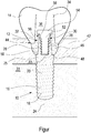
- the figure shows a schematic side view of a holding device with attached crown in a partially sectioned view.
- the holding device has an implant 10 and an intermediate element 12 which are connected to one another.
- a tooth replacement element 14 is placed, in particular glued.
- the implant 10 has an implant shaft 16. This in FIG. 1 non-cut part of the implant has a thread 20 on an outer side 18. This makes it possible to arrange the implant 10 in a jaw bone 22, in particular to screw.
- An implant head 25 with a projection 26 adjoins the implant shaft 16, which is rotationally symmetrical with respect to a longitudinal axis 24. This is preferably not rotationally symmetrical, but has, for example, a hexagonal or octagonal configuration, so that the projection 26 also serves as a tool attachment to screw the implant 10 into the jawbone 22.
- the intermediate element 12 has a recess 28. This is, in particular with respect to the longitudinal axis 24 arranged centrally in the intermediate element 12.
- the recess 28 is preferably formed congruent to the shape of the projection 26. This avoids a rotation or rotation of the intermediate element 12 on the implant introduced into the bone.
- a fixing member 30 is provided, which is a screw in the illustrated embodiment.
- the screw 30 is arranged in a through hole 32 of the intermediate element 12 and screwed into the projection 26 of the implant head 25.
- the projection 26 of the implant head 25 may have an opening or blind bore 33, which is open in the direction of the intermediate element 12.
- the intermediate element 12 has a projection 28 or projection 34 lying opposite the recess 28. This protrudes into a recess 36 of the tooth replacement element 14.
- the projection 34 and the recess 36 are in this case preferably again formed congruent.
- the implant 10 is anchored in the bone 22 by screwing in a first step. This is followed by sewing or Closing the gum 42 so that the implant 10 grows and is firmly connected to the bone 22. In the next step, the gum 42 is opened, since the implant 10 has an implant head 25, which is arranged above the jawbone 22 within the gum 42, the gum does not have to be opened to the bone.
- the intermediate element with a provisional crown outside mesiodistal and occlusal contact could already be screwed on after the implant placement and the gums around it sewn up. This has the advantage that in a later prosthetic restoration an already anatomically correctly shaped gingival socket is formed.
- the intermediate element 12 is subsequently fixed by means of the screw 30 in the projection 26 of the implant head 25.
- the intermediate element 12 has been previously processed in this way, in particular by grinding, and adapted to the individual tooth situation.
- the tooth replacement element 14 is placed by gluing on the intermediate element 12.
- the dental prosthetic item 14 is an anterior tooth crown or the like, it does not have an opening 36, as such an opening for the screw 30 can not be attached due to palatal angulation.
- the tooth replacement element 14 is placed on the intermediate element 12 by bonding by means of cement or other adhesive material in an anterior situation. Since the gap 44 between the intermediate member 12 and the dental prosthesis element 14 is located at anterior teeth only slightly below a top of the gum, excess cement material or the like can be easily removed, so that no irritation of the gums occur.
- the dental prosthesis element 14 has an opening 36. In this respect, it is possible, the tooth replacement element 14 outside the mouth by gluing with the help of cement or other adhesive material to bond with the intermediate element 12. The cement or adhesive material residues exiting in the region of the gap 44 can be removed before the intermediate element 12 connected to the dental prosthesis element 14 is fixed in the attachment 26 by means of the screw 30.
- the intermediate element 12 has a preferably circumferential collar 46. This has a preferably flat, flat bottom 48, which rests on a preferably flat and flat top 50 of the implant head. When fixing the intermediate element 12 by means of the screw 30, the underside 48 can be pressed against the support surface 50. This is in particular possible without play, since the material of the intermediate element 12 has a certain elasticity.
- the fixing element 30, which is designed in particular as a screw, has a shank 52 and a head 54. On an underside of the head 54, a recess 56 is provided.
- the recess 56 which is formed circumferentially, in this case has an inclined surface 58.
- the oblique surface 58 is provided a corresponding obliquely formed surface 60 opposite to the holding element 12.
Landscapes
- Health & Medical Sciences (AREA)
- Oral & Maxillofacial Surgery (AREA)
- Orthopedic Medicine & Surgery (AREA)
- Dentistry (AREA)
- Epidemiology (AREA)
- Life Sciences & Earth Sciences (AREA)
- Animal Behavior & Ethology (AREA)
- General Health & Medical Sciences (AREA)
- Public Health (AREA)
- Veterinary Medicine (AREA)
- Engineering & Computer Science (AREA)
- Ceramic Engineering (AREA)
- Dental Prosthetics (AREA)
Abstract
Eine Halteeinrichtung für Zahnersatzelemente (14) weist ein Implantat (10) und ein Zwischenelement (12) auf. Das Implantat (10) ist vorzugsweise durch Verschrauben in einem Kieferknochen (22) fixiert. Das Implantat (10) weist einen Implantatschaft (16) sowie einen Implantatkopf (25) auf. Der Implantatschaft (16) ragt über den Kieferknochen (22) hinaus in das Zahnfleisch (42). Mit dem Implantatkopf (25) ist ein Zwischenelement (12) verbunden. Das Zwischenelement (12) ist im Wesentlichen innerhalb des Zahnfleisches angeordnet und dient zur Aufnahme eines Zahnersatzelements (14). In einer Ausführungsform ist das Zwischenelement aus einem elastischen Material hergestellt. In einer anderen Ausführungsform weist der Implantatkopf einen Ansatz auf, der in eine Ausnehmung des Zwischenelements ragt. In einer weiteren Ausführungsform weist die Halteeinrichtung eine Schraube mit einem Kopf auf, wobei die Unterseite des Kopfes eine Einbuchtung aufweist.

Description
Die Erfindung betrifft eine Halteeinrichtung für Zahnersatzelemente.The invention relates to a holding device for dental prosthesis elements.
Zur Zahnrestauration ist es bekannt, Implantate im Kieferknochen zu fixieren. Mit dem Zahnimplantat wird sodann ein Zahnersatzelement, wie eine Krone, eine Brücke oder dergleichen, verbunden. Das Implantat wird zunächst in den Kieferknochen eingebracht, wobei es beispielsweise bekannt ist, das Implantat in den Kieferknochen einzuschrauben. Nach dem Anordnen des Implantats im Kieferknochen wird das Zahnfleisch des Patienten teilweise oder vollständig verschlossen, so dass eine Einheilung des Implantats erfolgt. Sobald das Implantat durch Einheilung fest in dem Knochen verankert ist, wird auf das Implantat die dentale Krone oder dergleichen aufgesetzt. Dies erfolgt derart, dass in einer Öffnung der Krone üblicherweise Zement vorgesehen wird und sodann die Krone oder dergleichen auf einen am Implantat vorgesehenen Ansatz aufgesetzt wird. Um ein sicheres Verbinden zu gewährleisten, muss ein Überschuss an Zement in der Ausnehmung der Krone vorgesehen werden. Dies führt dazu, dass der überschüssige Zement seitlich herausgedrückt wird und entfernt werden muss. Durch verbleibende Zementüberschüsse am unteren Kronenrand kann eine Reizung des Zahnfleisches auftreten. Anstatt Zement können auch andere Verbindungsmaterialien verwendet werden, wobei hierbei dieselbe Problematik besteht.For tooth restoration, it is known to fix implants in the jawbone. A tooth replacement element, such as a crown, a bridge or the like, is then connected to the dental implant. The implant is first introduced into the jawbone, it being known, for example, to screw the implant into the jawbone. After placing the implant in the jawbone, the gum of the patient is partially or completely closed, so that a healing of the implant takes place. Once the implant is firmly anchored by healing in the bone, the dental crown or the like is placed on the implant. This is done in such a way that in an opening of the crown cement is usually provided and then the crown or the like is placed on a provided on the implant approach. In order to ensure a secure connection, an excess of cement must be provided in the recess of the crown. This causes the excess cement to be pushed out laterally and must be removed. Remaining excess cement at the lower margin of the crown may irritate the gums. Instead of cement, other connecting materials can be used, whereby the same problem exists.
Ferner sind Halteeinrichtungen für Zahnersatzelemente mit einem zweiteiligen Implantat bekannt. Ein üblicherweise aus Titan hergestelltes Implantat wird wiederum im Kieferknochen angeordnet, wobei eine Oberseite des Implantats mit der Oberseite des Kieferknochens in eingesetztem Zustand abschließt. Auch dieses Implantat muss zunächst in den Kieferknochen eingebracht werden und dort einheilen. Das zweiteilige Implantat weist im Inneren eine Bohrung mit Gewinde auf, in die, nachdem das Implantat in dem Kieferknochen eingewachsen ist, ein zweites Implantatteil eingeschraubt wird. Mit diesem zweiten Implantatteil, das innerhalb des Zahnfleisches angeordnet ist, wird sodann die Krone oder dergleichen verbunden. Das zweite Implantatteil kann hierbei unterschiedlich ausgebildet sein, so dass beispielsweise die Zahnfleischhöhe bzw. die unterschiedliche Papillenhöhe bei Frontzähnen oder bei Seitenzähnen berücksichtigt werden kann. Ein derartiges zweiteiliges Implantat weist jedoch den Nachteil auf, dass zwischen den beiden Implantatteilen konstruktiv bedingt ein noch so kleiner Spalt bleibt. Hier können durch Kaubewegungen im Implantatsystem Mikrobewegungen auftreten, die die Stabilität verringern. Insbesondere besteht hierbei jedoch die Gefahr, dass Bakterien am Rand des Spalts und / oder am Außengewinde zwischen Implantat und Knochen eindringen und tief in den Knochen wandern.Furthermore, holding devices for dental prosthesis elements with a two-part implant are known. An implant usually made of titanium is in turn arranged in the jawbone, with an upper side of the implant terminating in the inserted state with the upper side of the jawbone. Also, this implant must first be introduced into the jawbone and heal there. The two-part implant has a threaded bore inside, into which, after the implant has grown into the jawbone, a second implant part is screwed. With this second implant part, which is arranged within the gum, then the crown or the like is connected. The second implant part may in this case be designed differently, so that, for example, the gum height or the different papilla height in anterior teeth or posterior teeth can be taken into account. However, such a two-part implant has the disadvantage that, due to the design, even the smallest gap remains between the two implant parts. As a result of chewing movements in the implant system, micro-movements can occur that reduce stability. In particular, however, there is a risk that bacteria penetrate at the edge of the gap and / or on the external thread between the implant and bone and migrate deeply into the bone.
Aufgabe der Erfindung ist es, eine Halteeinrichtung für Zahnelemente zu schaffen, bei der die Gefahr von Irritationen durch Zement oder dergleichen verringert und gleichzeitig auch die Gefahr des Eindringens von Bakterien verringert ist.The object of the invention is to provide a holding device for dental elements, in which the risk of irritation by cement or the like is reduced and at the same time the risk of bacterial ingress is reduced.
Die Lösung der Aufgabe erfolgt erfindungsgemäß durch eine Halteeinrichtung für Zahnersatzelemente gemäß Anspruch 1.The object is achieved by a holding device for dental prosthesis elements according to claim 1.
Die erfindungsgemäße Halteeinrichtung für Zahnersatzelemente wie Kronen, künstliche Zähne und dergleichen weist ein Implantat zur Fixierung in einem Kieferknochen auf. Die Fixierung erfolgt hierbei insbesondere durch Einschrauben in den Kieferknochen. Das Implantat weist einen Implantatschaft zur Anordnung in dem Kieferknochen und einen Implantatkopf zur Anordnung im Zahnfleisch auf. Der Implantatkopf steht somit in eingesetztem Zustand über den Kieferknochen vor. Nach dem Einheilen des Implantats muss somit das Zahnfleisch nicht bis zur Knochenoberfläche geöffnet werden. Das Eindringen von Bakterien in diesen Bereich ist somit vermieden. Mit dem Implantatkopf ist erfindungsgemäß ein Zwischenelement verbunden. Das Zwischenelement dient zur Aufnahme des Zahnersatzelementes. Das Zwischenelement ist erfindungsgemäß derart ausgebildet, dass es zumindest im Wesentlichen innerhalb des Zahnfleisches angeordnet ist. Das Zwischenelement kann jedoch auch geringfügig über das Zahnfleisch vorstehen. Dies ist insofern möglich, da es in bevorzugter Ausführungsform möglich ist, das Zwischenelement einzufärben bzw. aus eingefärbtem Material herzustellen.The holding device according to the invention for dental prosthesis elements such as crowns, artificial teeth and the like has an implant for fixation in a jawbone. The fixation takes place here in particular by screwing into the jawbone. The implant has an implant shaft for placement in the jawbone and an implant head for placement in the gum. The implant head is thus in the inserted state over the jawbone. After healing the implant, the gums do not have to be opened to the bone surface. The penetration of bacteria into this area is thus avoided. According to the invention, an intermediate element is connected to the implant head. The intermediate element serves to receive the tooth replacement element. The intermediate element according to the invention is designed such that it is arranged at least substantially within the gum. However, the intermediate element may also protrude slightly above the gum. This is possible insofar as it is possible in a preferred embodiment to dye the intermediate element or to produce it from dyed material.
In besonders bevorzugter Ausführungsform erfolgt das Verbinden des Zwischenelements mit dem Implantat, insbesondere dem Implantatkopf mit Hilfe eines Fixierelements wie einer Schraube, so dass in diesem Bereich keine Zementreste oder andere Klebemittelreste eine Irritierung des Zahnfleisches hervorrufen können. Die Verbindung des Zahnersatzelements mit dem Zwischenelement kann sodann durch Verkleben insbesondere mittels Zement oder einem anderen Klebemittel erfolgen. Die hierbei gegebenenfalls austretenden Zement- oder Klebemittelreste treten in einem Bereich auf, der nur geringfügig unterhalb der Oberseite des Zahnfleisches angeordnet ist. Insofern ist es auf einfache Art und Weise möglich entsprechende Zement- und/oder Klebmittelreste rückstandsfrei und glatt zu entfernen, so dass eine spätere ständige Irritation des Zahnfleisches vermieden ist.In a particularly preferred embodiment, the connection of the intermediate element with the implant, in particular the implant head with the aid of a fixing element such as a screw, so that no cement residues or other adhesive residues can cause irritation of the gums in this area. The connection of the dental prosthesis element with the intermediate element can then be done by gluing in particular by means of cement or another adhesive. The cement or adhesive residues which may escape in this case occur in a region which is arranged only slightly below the upper side of the gum. In this respect, it is possible in a simple manner to remove residues of cement and / or adhesive residue-free and smooth, so that a subsequent constant irritation of the gum is avoided.
In besonders bevorzugter Ausführungsform weist das Zwischenelement ein Material mit größerer Elastizität als das Implantat und/oder als das Zahnersatzelement auf. Insbesondere ist das Zwischenelement aus einem Material mit entsprechend größerer Elastizität hergestellt. Aufgrund des Verwendens eines derartigen Materials wirkt das Zwischenelement als eine Art Dämpfungselement. Bei natürlichen Zähnen ist die Zahnwurzel elastisch im Kieferknochen gehalten, so dass der Zahn gegenüber dem Kieferknochen geringfügig bewegbar ist. Dies ist bei künstlichen Zähnen nicht der Fall, da das Implantat fest im Kieferknochen verankert ist. Dies kann bei künstlichen Zähnen dazu führen, dass bei starken Belastungen Abplatzungen bei dem Zahnersatzelement wie der Krone oder der Brücke auftreten. Durch die bevorzugte erfindungsgemäße Ausgestaltung des Zwischenelements aus einem Material mit zumindest etwas größerer Elastizität als das Implantat und/oder das Zahnersatzelement können derartige Abplatzungen vermieden werden und der künstliche Zahn weist Eigenschaften auf, die dem natürlichen Zahn sehr ähnlich sind.In a particularly preferred embodiment, the intermediate element has a material with greater elasticity than the implant and / or as the tooth replacement element. In particular, the intermediate element is made of a material with a correspondingly greater elasticity. Due to the use of such a material, the intermediate element acts as a kind of damping element. In natural teeth, the tooth root is elastic in the jawbone held so that the tooth is slightly movable relative to the jawbone. This is not the case with artificial teeth because the implant is firmly anchored in the jawbone. In the case of artificial teeth, this can cause flaking in the case of the denture element such as the crown or the bridge in the case of heavy loads. As a result of the preferred embodiment of the intermediate element according to the invention made of a material with at least somewhat greater elasticity than the implant and / or the tooth replacement element, such flaking can be avoided and the artificial tooth has properties that are very similar to the natural tooth.
Vorzugsweise weist das Zwischenelement dentalen Kunststoff und/oder dentale Keramik auf bzw. ist aus derartigen Materialien hergestellt. Insbesondere kann für das Zwischenelement auch poröse mit Kunststoff infiltrierte Keramik verwendet werden.Preferably, the intermediate element comprises dental plastic and / or dental ceramic or is made of such materials. In particular, it is also possible to use porous plastic infiltrated ceramic for the intermediate element.
Besonders geeignet als Material für das Zwischenelement ist das unter dem Namen VITA ENAMIC® vertriebene Material.Particularly suitable material for the intermediate element is the material sold under the name VITA ENAMIC®.
Insbesondere ist es bevorzugt, dass Zwischenelement aus Material herzustellen, das beschleifbar ist. Beschleifbar meint in diesem Zusammenhang, dass das Zwischenelement vor dem Einsetzen an die anatomische Situation angepasst werden kann. Bei dem erfindungsgemäß verwendeten Material ist das Beschleifen aufgrund der Materialeigenschaften in wesentlich größerem Umfang als bei anderen Materialien wie Zirkonoxid oder Titan möglich. Das erfindungsgemäß verwendete Material weist insbesondere den Vorteil auf, dass durch das Beschleifen keine Beeinträchtigung des Materials, insbesondere der Materialzusammensetzung, erfolgt bzw. das Risiko einer entsprechenden Beeinträchtigung sehr gering ist. Beispielsweise wird zur Anpassung der Form der rotationssystemtische Formkörper des Zwischenelements in der Höhe (Marginline der Krone) oder der mesial/distal Ausdehnung oder palatinale/labiale Ausdehnung anpassen. Der Vorteil eines beschleifbaren Zwischenelements ist, dass die Situation im Mund nach der Einheilung individuelloptimal für die Insertation des Zahnrestaurationsaufbaus vorbereitet werden kann. In einem Sonderfall könne der Zahnarzt sogar ausnahmsweise im Mund des Patienten durch Schleifen kleinere nachträgliche Formkorrekturen am künstlichen Zwischenelement vornehmen. Ein nachträgliches Beschleifen von bereits im Patientenmund vorhandenem Implantatmaterial wird im bisherigen Stand der Technik, bei dem üblicherweise Titan oder Zirkonoxid zum Einsatz kommt, nur in geringem Maße zugelassen.In particular, it is preferred that the intermediate element be made of material that can be ground. Abradable means in this context that the intermediate element can be adapted to the anatomical situation before insertion. In the case of the material used according to the invention, the grinding due to the material properties is possible to a much greater extent than with other materials such as zirconium oxide or titanium. The material used according to the invention has the particular advantage that the grinding does not adversely affect the material, in particular the material composition, or the risk of a corresponding impairment is very low. For example, in order to adapt the shape, the rotational-shaped body of the intermediate element will be adjusted in height (margin line of the crown) or mesial / distal extension or palatal / labial extension. The advantage of a loopable intermediate element is that the situation in the mouth after healing can be prepared individually for the insertion of the dental restoration structure. In a special case, the dentist could even exceptionally make in the mouth of the patient by grinding smaller subsequent shape corrections on the artificial intermediate element. Subsequent grinding of implant material already present in the patient's mouth is only permitted to a limited extent in the prior art, in which titanium or zirconium oxide is usually used.
Das vorzugsweise für das Zwischenelement verwendete Material weist insbesondere eine Biegefestigkeit von 130-360 MPa, insbesondere von 150 - 160 bzw. 250-350 MPa und einen Elastizitätsmodul von 20-45 GPa auf. Das bevorzugte Material VITA ENAMIC IS hat eine Biegefestigkeit von 150-160 MPa und ein Elastizitätsmodul von ca. 30 GPa.Implantatgetragene Molarenkronen aus VITA ENAMIC IS auf L-TiBase Klebebasen und Straumann bone Level Implantatsystem hielten in einem statischen Bruchlasttest einer Belastung von im Mittel ca. 926 N stand. Im Vergleich zur mittleren maximalen Kaukraft von etwa 490 N und Maximalwerten von 725 N erreichten die untersuchten Molarenkronen ein höheres Belastungsniveau. In einem dynamischen Bruchlasttest wurden 14 VITA ENAMIC Kronen im Kausimulator getestet. Die Kronen wurden nach dem Ätzen auf Komposit-Stümpfen (E-Modul ca. 18 GPa) mit Variolink II (Ivoclar Vivadent) zementiert, in Technovit 4000 (Heraeus Kulzer) eingebettet und in 37°C warmem Wasser für 24 Stunden gelagert. Die Kronen wurden nach dem Auslagern in dem Kausimulator zyklisch belastet: 198 N Last, 1,2 Millionen Zyklen, 1,6 Hz Frequenz, 3 mm Steatitkugel als Antagonist, TC 5 - 55 °C. Keine der VITA ENAMIC Kronen zeigte während der dynamischen Kaubelastung Fehler (siehe: Universitätsklinikum für Zahn-, Mund- und Kieferheilkunde Freiburg, Abtlg. Für Zahnärztliche Prothetik, Dr. Asma Bilkhair, Bericht 12/11 ([2], vgl. S. 34)).The material preferably used for the intermediate element has in particular a flexural strength of 130-360 MPa, in particular of 150-160 or 250-350 MPa and a modulus of elasticity of 20-45 GPa. The preferred material VITA ENAMIC IS has a flexural strength of 150-160 MPa and a modulus of elasticity of approx. 30 GPa. Implant-supported molar crowns made of VITA ENAMIC IS on L-TiBase adhesive bases and Straumann bone level implant system maintained a load of on average approx 926 N stood. In comparison to the mean maximum chewing force of about 490 N and maximum values of 725 N, the investigated molar crowns reached a higher load level. In a dynamic fracture load test, 14 VITA ENAMIC crowns were tested in the chewing simulator. The crowns were cemented after etching on composite stumps (modulus about 18 GPa) with Variolink II (Ivoclar Vivadent), embedded in Technovit 4000 (Heraeus Kulzer) and stored in 37 ° C water for 24 hours. The crowns were cycled after aging in the chewing simulator: 198 N load, 1.2 million cycles, 1.6 Hz frequency, 3 mm steatite ball as antagonist, TC 5 - 55 ° C. None of the VITA ENAMIC crowns showed any defects during the dynamic chewing load (see: Department of Dentistry, Oral and Maxillofacial Surgery Freiburg, Dept. of Prosthodontics, Dr. Asma Bilkhair,
Bei einer bevorzugten Weiterbildung der Erfindung weist der Implantatkopf einen Ansatz auf, der in eine Ausnehmung des Zwischenelements ragt. Hierdurch ist eine gute Fixierung, insbesondere eine formschlüssige Fixierung zwischen dem Zahnersatzelement und dem Implantat möglich.In a preferred embodiment of the invention, the implant head has a projection which projects into a recess of the intermediate element. hereby is a good fixation, in particular a positive fixation between the dental prosthesis element and the implant possible.
Der Ansatz des Implantatkopfes ist vorzugsweise derart ausgebildet, dass er von dem Zwischenelement insbesondere seitlich umgeben ist. Insbesondere erfolgt ein vollständiges seitliches Umgeben des Ansatzes durch das Zwischenelement. Die Ausnehmung an dem Zwischenelement ist in besonders bevorzugter Ausführungsform derart ausgebildet, dass diese ausschließlich eine in Richtung des Implantats weisende Öffnung aufweist, in die sodann der Ansatz eingesteckt wird.The approach of the implant head is preferably designed such that it is surrounded by the intermediate element in particular laterally. In particular, a complete lateral surrounding of the approach takes place through the intermediate element. The recess on the intermediate element is formed in a particularly preferred embodiment such that it has only one pointing in the direction of the implant opening into which the neck is then inserted.
In besonders bevorzugter Ausführungsform ist der im Kieferknochen angeordnete Implantatschaft rotationssymmetrisch. Der mit dem Implantatkopf verbundene Ansatz muss nicht rotationssymmetrisch sein, sondern ist in besonders bevorzugter Ausführungsform nicht rotationssymmetrisch ausgebildet. Der Implantatschaft weist in weiterer bevorzugter Ausführungsform an einer Außenseite ein Gewinde auf. Hierdurch ist es möglich, das Implantat durch Einschrauben im Knochen zu befestigen. Insofern ist ein nicht rotationssymmetrischer Implantatkopf oder Ansatz bevorzugt, da der Implantatkopf bzw. Ansatz sodann gleichzeitig zur Aufnahme eines Werkzeugs bzw. zum Verbinden mit einem Werkzeug dienen kann. Der Ansatz hat somit neben der Funktion des Verbindens mit dem Zwischenelement auch die Funktion eines Werkzeugansatzes.In a particularly preferred embodiment, the implant shaft arranged in the jawbone is rotationally symmetrical. The approach connected to the implant head does not have to be rotationally symmetrical, but in a particularly preferred embodiment is not rotationally symmetrical. In a further preferred embodiment, the implant shaft has a thread on an outer side. This makes it possible to attach the implant by screwing in the bone. In this respect, a non-rotationally symmetrical implant head or projection is preferred since the implant head or projection can then simultaneously serve to receive a tool or to connect to a tool. The approach thus has the function of a tool approach in addition to the function of connecting with the intermediate element.
Die in dem Zwischenelement vorgesehene Ausnehmung ist in besonders bevorzugter Ausführungsform kongruent zu dem Ansatz des Implantats. Da in besonders bevorzugter Ausführungsform der Ansatz nicht rotationssymmetrisch ist, ist auch die kongruent ausgebildete Ausnehmung vorzugsweise nicht rotationssymmetrisch. Hierdurch ist ein Formschluss sichergestellt, so dass ein Verdrehen des Zwischenelements auf dem Implantatkopf vermieden ist.The recess provided in the intermediate element is, in a particularly preferred embodiment, congruent with the projection of the implant. Since in a particularly preferred embodiment, the approach is not rotationally symmetric, and the congruent recess is preferably not rotationally symmetric. As a result, a positive connection is ensured, so that a rotation of the intermediate element is avoided on the implant head.
Bei einer weiteren bevorzugten Ausführungsform weist das Zwischenelement einen insbesondere umlaufenden Kragen auf. Der Kragen weist eine vorzugsweise ebene Unterseite auf. Diese Unterseite liegt insbesondere flächig an einem Ansatz des Implantatkopfes auf. Der Ansatz ist vorzugsweise ringförmig ausgebildet. Durch eine derartige insbesondere flächige Auflage zwischen dem Zwischenelement und dem Implantatkopf kann eine spielfreie Verbindung hergestellt werden. Dies weist insbesondere den Vorteil auf, dass keine Mikrobewegungen auftreten, die ein Lösen der Verbindung zwischen dem Zwischenelement und dem Implantat bewirken könnten.In a further preferred embodiment, the intermediate element has a particular circumferential collar. The collar has a preferably flat underside. This underside lies in particular flat on a shoulder of the implant head. The approach is preferably annular. By such a particular flat support between the intermediate element and the implant head a backlash-free connection can be made. This has the particular advantage that no micro-movements occur that could cause a release of the connection between the intermediate element and the implant.
Bei einer weiteren besonders bevorzugten Ausführungsform der Erfindung sind der Implantatkopf und das Zwischenelement mittels eines Fixierelements miteinander verbunden. Das Fixierelement ist vorzugsweise derart angeordnet, dass es zu einer axialen Fixierung dient. Hierbei kann das Fixierelement stiftförmig ausgebildet sein und beispielsweise in eine Öffnung ragen, wobei die Öffnung vorzugsweise am Implantat, insbesondere am Ansatz des Implantatkopfes, vorgesehen ist. Das Fixierelement ist beispielsweise stiftförmig ausgebildet und weist Rastnasen oder Rastelemente auf. Insbesondere kann ein derartig stiftartig ausgebildetes Fixierelement fest mit dem Zwischenelement verbunden oder einstückig mit diesem ausgebildet sein.In a further particularly preferred embodiment of the invention, the implant head and the intermediate element are connected to one another by means of a fixing element. The fixing element is preferably arranged such that it serves for an axial fixation. Here, the fixing element may be formed pin-shaped and project, for example, into an opening, wherein the opening is preferably provided on the implant, in particular at the base of the implant head. The fixing element is, for example, pin-shaped and has latching noses or latching elements. In particular, such a pin-like trained fixing can be firmly connected to the intermediate element or formed integrally therewith.
Insbesondere ist die Öffnung zur Aufnahme des Fixierelements am Ansatz des Implantatkopfes derart angeordnet, dass die Öffnung an einer Oberseite des Implantatkopfes, die in Richtung des Zwischenelements weist, offen ist. Da das Fixierelement in bevorzugter Ausführungsform zur axialen Fixierung des Zwischenelements dient, ist für eine radiale Fixierung, um ein Verdrehen des Zwischenelements zu vermeiden, vorzugsweise ein weiteres Fixierelement vorgesehen. Dies kann bei einer nicht rotationssymmetrischen Ausgestaltung des Ansatzes sowie der Ausnehmung entfallen, da bereits hierdurch eine rotatorische Fixierung erfolgt.In particular, the opening for receiving the fixing element is arranged at the base of the implant head such that the opening is open at an upper side of the implant head facing in the direction of the intermediate element. Since the fixing element is used in a preferred embodiment for the axial fixation of the intermediate element, a further fixing element is preferably provided for a radial fixation in order to avoid a rotation of the intermediate element. This can be omitted in a non-rotationally symmetrical embodiment of the approach and the recess, as this is already a rotational fixation.
In besonders bevorzugter Weiterbildung der Erfindung handelt es sich bei dem Fixierelement um ein gesondertes Bauteil. Dieses kann mit dem Zwischenelement verbunden werden. Insbesondere weist das Zwischenelement eine Bohrung auf, in der das Fixierelement teilweise angeordnet ist. Hierbei kann es sich wiederum um ein stiftartiges Fixierelement handeln, das mit dem Zwischenelement durch eine Rastverbindung oder dergleichen verbunden wird.In a particularly preferred embodiment of the invention is in the Fixing element around a separate component. This can be connected to the intermediate element. In particular, the intermediate element has a bore in which the fixing element is partially arranged. This may in turn be a pin-like fixing element, which is connected to the intermediate element by a latching connection or the like.
Besonders bevorzugt ist die Bohrung in dem Zwischenelement als Durchgangsbohrung ausgebildet, durch die das Fixierelement hindurch gesteckt werden kann. Die Fixierung des Fixierelements erfolgt sodann im Implantatkopf, insbesondere im Ansatz des Implantatkopfes. Beispielsweise kann es sich bei dem Fixierelement um eine Schraube handeln, die in den Implantatkopf, insbesondere den Ansatz des Implantatkopfes, eingeschraubt wird und hierdurch das Zwischenelement axial fixiert.Particularly preferably, the bore in the intermediate element is designed as a through-hole through which the fixing element can be inserted. The fixation of the fixing then takes place in the implant head, in particular in the neck of the implant head. For example, the fixing element may be a screw which is screwed into the implant head, in particular the projection of the implant head, and thereby axially fixes the intermediate element.
Da das Zwischenelement in besonders bevorzugter Ausführungsform aus einem Material hergestellt ist, das eine gewisse Elastizität aufweist, kann das Zwischenelement insbesondere bei einer Fixierung durch eine Schraube geringfügig verformt bzw. zusammengedrückt werden. Dies hat insbesondere den Vorteil, dass zwischen der Auflagefläche des Implantatkopfes und einer Unterseite des Zwischenelements insbesondere einer Unterseite des Kragens des Zwischenelements eine spielfreie Verbindung realisiert ist. Hierdurch ist ein Lösen des Zwischenelements vom Implantatkopf durch Auftreten von Mikrobewegungen vermieden.Since the intermediate element is made in a particularly preferred embodiment of a material having a certain elasticity, the intermediate element can be slightly deformed or compressed in particular in a fixation by a screw. This has the particular advantage that a play-free connection is realized between the support surface of the implant head and a lower side of the intermediate element, in particular a lower side of the collar of the intermediate element. As a result, a release of the intermediate element from the implant head by the occurrence of micro-movements is avoided.
Vorzugsweise ist das Implantat und/oder das Zahnersatzelement aus Zirkonoxid hergestellt. Bei aus Zirkonoxid hergestelltem Zahnersatz handelt es sich um keramische Werkstücke mit herausragenden Materialeigenschaften hinsichtlich ihrer Bioverträglichkeit, Stabilität und Ästhetik. Dabei reicht die Einsatzbreite des Materials von konservierenden Restaurationen über Kronen und Brücken bis in die Implantatprothetik hinein. Zirkoniumdioxid (chemische Charakterisierung: ZrO2 + HfO2 + Y2O3 > 99 %) gehört zu den sogenannten Oxidkeramiken und zeigt Eigenschaften, die Metallen vergleichbar oder ihnen zum Teil sogar überlegen sind. Als Keramik ist es korrosionsfrei und zeichnet sich durch eine hohe Biegefestigkeit und Bruchzähigkeit aus.Preferably, the implant and / or the dental prosthesis element is made of zirconium oxide. Dental prostheses made from zirconia are ceramic workpieces with outstanding material properties in terms of biocompatibility, stability and aesthetics. The range of application of the material ranges from conserving restorations over crowns and bridges to implant prosthetics. Zirconia (chemical characterization: ZrO 2 + HfO 2 + Y 2 O 3 > 99%) belongs to the so-called oxide ceramics and exhibits properties that are comparable or comparable to metals sometimes even superior. As a ceramic, it is corrosion-free and characterized by a high flexural strength and fracture toughness.
Da das Zwischenelement in besonders bevorzugter Ausführungsform aus einem insbesondere durch Schleifen bearbeitbarem Material hergestellt ist, ist es auf einfache Weise möglich, das Zwischenelement an die Patientensituation anzupassen. Beispielsweise kann die Höhe des Zwischenelements an die Zahnfleischhöhe bzw. die unterschiedliche Papillenhöhe des Patienten im entsprechenden Kieferbereich angepasst werden. Besonders im Frontzahnbereich kann das Zwischenelement bei der Verwendung entsprechend bearbeitet werden, was ästhetische und funktionale Vorteile mit sich bringtSince the intermediate element is made in a particularly preferred embodiment of a particular editable by grinding material, it is easily possible to adapt the intermediate element to the patient situation. For example, the height of the intermediate element can be adapted to the gum height or the different papilla height of the patient in the corresponding jaw area. Especially in the anterior region, the intermediate element can be processed appropriately during use, which brings aesthetic and functional advantages
Im Bereich der Seitenzähne ist der ästhetische Anspruch im Weichgewebe üblicherweise deutlich geringer als im Bereich der Frontzähne. Im Bereich der Seitenzähne ist es möglich, das Zahnersatzelement wie die Krone durch Zement oder ein anderes Klebematerial mit dem Zwischenelement zu verbinden. Diese Verbindung kann extraoral (außerhalb des Mundes) erfolgen, so dass eine vollständige Entfernung von Zement- oder Klebematerialresten auf einfache Weise erfolgen kann. Insbesondere ist dies für den Patienten deutlich angenehmer. Bevorzugt ist es hierbei, dass das Zahnersatzelement wie die Krone ebenfalls eine Durchgangsöffnung aufweist, so dass das zuvor mit dem Zwischenelement verbundene Zahnersatzelement mittels des Fixierelements wie einer Schraube zusammen mit dem Zwischenelement mit dem Ansatz des Implantatkopfes verbunden insbesondere verschraubt werden kann.In the area of the posterior teeth, the aesthetic requirement in soft tissue is usually much lower than in the area of the anterior teeth. In the area of the posterior teeth, it is possible to connect the dental prosthesis element such as the crown by cement or another adhesive material with the intermediate element. This compound can be extraorally (outside the mouth) so that complete removal of cement or adhesive remnants can be done easily. In particular, this is much more pleasant for the patient. It is preferred in this case that the dental prosthesis element as the crown also has a through opening, so that the previously connected to the intermediate element dental prosthesis element can be screwed together by means of the fixing element such as a screw together with the intermediate element with the approach of the implant head.
Bei Verwendung der erfindungsgemäßen Halteeinrichtung bei Frontzähnen ist es aufgrund der Angulation der Frontzähne oft nicht möglich, in dieser eine palatinale Durchgangsbohrung zur Aufnahme des Fixierelements vorzusehen. Im Frontzahnbereich ist es daher bevorzugt das Zwischenelement zunächst mit dem eingewachsenen Implantat, das heißt mit dem Implantatkopf über ein Fixierelement wie eine Schraube zu verbinden. Anschließend erfolgt ein Verbinden des Zahnersatzelementes mit Hilfe von Zement oder einem anderen Klebematerial im Mund des Patienten. Der Bereich zwischen dem Zwischenelement und dem Zahnersatzelement liegt nur geringfügig unterhalb der Oberseite des Zahnfleisches. Insbesondere liegt dieser Bereich ca. 1mm unter der Oberseite des Zahnfleisches. Insofern ist es möglich, die Zement- bzw. Klebemittelreste hier auf einfache Weise zu entfernen, so dass keine Irritation des Zahnfleisches bzw. des Knochens auftritt.When using the holding device according to the invention in front teeth, it is often not possible due to the angulation of the anterior teeth to provide in this a palatal through-hole for receiving the fixing. In the anterior region, it is therefore preferable to first connect the intermediate element with the ingrown implant, that is, with the implant head via a fixing element such as a screw. Subsequently, the tooth replacement element is connected by means of cement or another Adhesive material in the mouth of the patient. The area between the intermediate element and the dental prosthesis element lies only slightly below the upper side of the gum. In particular, this area is about 1mm below the top of the gum. In this respect, it is possible to remove the cement or adhesive residues here in a simple manner, so that no irritation of the gums or of the bone occurs.
In besonders bevorzugter Ausführungsform weist das Fixierelement einen Kopf und einen Schaft auf, wobei das Fixierelement vorzugsweise als Schraube ausgebildet ist. Der Kopf des Fixierelements weist an seiner Unterseite eine Einbuchtung auf. Diese erstreckt sich insbesondere um die gesamte Unterseite, da es sich bei dem Fixierelement vorzugsweise um ein rotationssymmetrisches Bauteil handelt. Die Einbuchtung ist vorzugsweise derart ausgebildet, dass sie eine nach innen weisende schräge Fläche aufweist. Die der Unterseite des Kopfes des Fixierelements gegenüberliegende Seite des Zwischenelements ist vorzugsweise komplementär ausgebildet. Eine derartige Einbuchtung an dem Kopf des Fixierelements hat den Vorteil, dass die auftretenden Kräfte insbesondere beim Verschrauben bzw. beim Anordnen des Fixierelements nach innen gerichtet sind. Dies hat den Vorteil, dass das Zwischenelement beim Fixieren mit dem Ansatz des Implantatkopfes nicht zerstört wird. Ein derartiges Risiko besteht bei radial nach außen auftretenden Kraftkomponenten.In a particularly preferred embodiment, the fixing element has a head and a shaft, wherein the fixing element is preferably designed as a screw. The head of the fixing element has a recess on its underside. This extends in particular around the entire underside, since the fixing element is preferably a rotationally symmetrical component. The recess is preferably formed such that it has an inwardly facing inclined surface. The underside of the head of the fixing element opposite side of the intermediate element is preferably formed complementary. Such an indentation on the head of the fixing element has the advantage that the forces occurring are directed in particular during screwing or when arranging the fixing element inwards. This has the advantage that the intermediate element is not destroyed when fixing with the approach of the implant head. Such a risk exists with radially outward force components.
Nachfolgend wird die Erfindung anhand einer bevorzugten Ausführungsform unter Bezugnahme auf die anliegenden Zeichnungen näher erläutert.The invention will be explained in more detail with reference to a preferred embodiment with reference to the accompanying drawings.
Die Figur zeigt eine schematische Seitenansicht einer Halteeinrichtung mit aufgesetzter Krone in teilweise geschnittener Ansicht.The figure shows a schematic side view of a holding device with attached crown in a partially sectioned view.
Die Halteeinrichtung weist ein Implantat 10 sowie ein Zwischenelement 12 auf, die miteinander verbunden sind. Auf das Zwischenelement 12 ist ein Zahnersatzelement 14 aufgesetzt, insbesondere aufgeklebt.The holding device has an
Das Implantat 10 weist einen Implantatschaft 16 auf. Dieser in
An den Implantatschaft 16, der zu einer Längsachse 24 rotationssymmetrisch ausgebildet ist, schließt sich ein Implantatkopf 25 mit einem Ansatz 26 an. Dieser ist vorzugsweise nicht rotationssymmetrisch ausgebildet, sondern weist beispielsweise eine sechs- oder achteckige Ausgestaltung auf, so dass der Ansatz 26 auch als Werkzeugansatz dient, um das Implantat 10 in den Kieferknochen 22 einzuschrauben.An
Das Zwischenelement 12 weist eine Ausnehmung 28 auf. Diese ist, insbesondere bezogen auf die Längsachse 24 mittig im Zwischenelement 12 angeordnet. Die Ausnehmung 28 ist vorzugsweise kongruent zur Form des Ansatzes 26 ausgebildet. Hierdurch ist ein Rotieren bzw. Verdrehen des Zwischenelements 12 auf dem in den Knochen eingebrachten Implantat vermieden.The
Zum axialen Fixieren ist ein Fixierelement 30 vorgesehen, bei dem es sich im dargestellten Ausführungsbeispiel um eine Schraube handelt. Die Schraube 30 ist in einer Durchgangsbohrung 32 des Zwischenelements 12 angeordnet und in den Ansatz 26 des Implantatkopfs 25 eingeschraubt. Hierzu kann der Ansatz 26 des Implantatkopfs 25 eine Öffnung bzw. Sackbohrung 33 aufweisen, die in Richtung des Zwischenelements 12 offen ist.For axial fixing a fixing
Das Zwischenelement 12 weist einen der Ausnehmung 28 gegenüberliegenden Ansatz bzw. Vorsprung 34 auf. Dieser ragt in eine Ausnehmung 36 des Zahnersatzelements 14. Der Ansatz 34 und die Ausnehmung 36 sind hierbei vorzugsweise wiederum kongruent ausgebildet.The
Zur Herstellung des Zahnersatzes wird in einem ersten Schritt das Implantat 10 durch Einschrauben im Knochen 22 verankert. Anschließend erfolgt ein Zunähen bzw. Verschließen des Zahnfleisches 42, so dass das Implantat 10 einwächst und fest mit dem Knochen 22 verbunden ist. Im nächsten Schritt erfolgt ein Öffnen des Zahnfleisches 42, da das Implantat 10 einen Implantatkopf 25 aufweist, der oberhalb des Kieferknochens 22 innerhalb des Zahnfleisches 42 angeordnet ist, muss das Zahnfleisch nicht bis zum Knochen geöffnet werden. Alternativ könnte das Zwischenelement mit einer provisorischen Krone außerhalb von mesiodistalen und okklusalem Kontakt bereits nach der Implantatinsertation aufgeschraubt und das Zahnfleisch drumherum zugenäht werden. Dies hat den Vorteil, dass bei einer späteren prothetischen Versorgung eine bereits anatomisch richtig ausgeformte Zahnfleischalveole ausgebildet ist.To produce the tooth replacement, the
Bei Frontzähnen erfolgt anschließend ein Fixieren des Zwischenelements 12 mittels der Schraube 30 in dem Ansatz 26 des Implantatkopfes 25. Das Zwischenelement 12 wurde hierbei zuvor entsprechend insbesondere durch Schleifen bearbeitet und an die individuelle Zahnsituation angepasst. Anschließend wird das Zahnersatzelement 14 durch Verkleben auf das Zwischenelement 12 aufgesetzt. Wenn es sich bei dem Zahnersatzelement 14 um eine Krone oder dergleichen eines Frontzahns handelt, weist diese keine Öffnung 36 auf, da eine derartige Öffnung für die Schraube 30 aufgrund der Angulation von palatinal nicht anzubringen ist. Insofern wird bei einer Frontzahnsituation das Zahnersatzelement 14 durch Verkleben mittels Zement oder einem anderen Klebematerial auf dem Zwischenelement 12 aufgesetzt. Da der Spalt 44 zwischen dem Zwischenelement 12 und dem Zahnersatzelement 14 bei Frontzähnen nur geringfügig unterhalb einer Oberseite des Zahnfleisches angeordnet ist, kann überschüssiges Zementmaterial oder dergleichen auf einfache Weise entfernt werden, so dass keine Irritationen des Zahnfleisches auftreten.In the case of anterior teeth, the
Wenn es sich bei dem Zahnersatzelement 14 um eine Krone oder dergleichen zum Ersatz eines Seitenzahns handelt weist das Zahnersatzelement 14 eine Öffnung 36 auf. Insofern ist es möglich, das Zahnersatzelement 14 außerhalb des Mundes durch Verkleben mit Hilfe von Zement oder einem anderen Klebematerial mit dem Zwischenelement 12 zu verkleben. Die im Bereich des Spalts 44 austretenden Zement- bzw. Klebematerialreste können entfernt werden, bevor das mit dem Zahnersatzelement 14 verbundene Zwischenelement 12 mit Hilfe der Schraube 30 in dem Ansatz 26 fixiert wird.If the
Das Zwischenelement 12 weist einen vorzugsweise umlaufenden Kragen 46 auf. Dieser weist eine vorzugsweise flache, ebene Unterseite 48 auf, die auf einer vorzugsweise flachen und ebenen Oberseite 50 des Implantatkopfes aufliegt. Beim Fixieren des Zwischenelements 12 mit Hilfe der Schraube 30 kann die Unterseite 48 gegen die Auflagefläche 50 gedrückt werden. Dies ist insbesondere spielfrei möglich, da das Material des Zwischenelements 12 eine gewisse Elastizität aufweist.The
Das Fixierelement 30, das insbesondere als Schraube ausgebildet ist, weist einen Schaft 52, sowie einen Kopf 54 auf. An einer Unterseite des Kopfs 54 ist eine Einbuchtung 56 vorgesehen. Die Einbuchtung 56, die umlaufend ausgebildet ist, weist hierbei eine schräge Fläche 58 auf. Der schrägen Fläche 58 ist eine entsprechend schräg ausgebildete Fläche 60 gegenüberliegend am Halteelement 12 vorgesehen. Beim Anziehen der Schraube 30 treten somit im Wesentlichen nur in axiale Richtung und radial nach innen gerichtete Kräfte auf. Hierdurch ist sichergestellt, dass beim Anziehen der Schraube 30 das Zwischenelement 12 nicht beschädigt wird.The fixing
Claims (16)
einem Implantat (10) zur Fixierung in einem Kieferknochen (22),
wobei das Implantat (10) einen Implantatschaft (16) zur Anordnung im Kieferknochen (22) und einen Implantatkopf (25) zur Anordnung im Zahnfleisch (42) aufweist und
einem mit dem Implantatkopf (25) verbindbaren Zwischenelement (12) zur Aufnahme des Zahnersatzelements (14) und zur Anordnung zumindest im Wesentlichen innerhalb des Zahnfleisches (42).Holding device for dental prosthesis elements, with
an implant (10) for fixation in a jawbone (22),
wherein the implant (10) has an implant shaft (16) for placement in the jawbone (22) and an implant head (25) for placement in the gum (42), and
a with the implant head (25) connectable intermediate element (12) for receiving the dental prosthesis element (14) and for arrangement at least substantially within the gum (42).
Priority Applications (2)
| Application Number | Priority Date | Filing Date | Title |
|---|---|---|---|
| EP18154910.6A EP3520730A1 (en) | 2018-02-02 | 2018-02-02 | Holding device for tooth replacement elements |
| PCT/EP2019/052284 WO2019149773A1 (en) | 2018-02-02 | 2019-01-30 | Retaining device for dental prosthesis elements |
Applications Claiming Priority (1)
| Application Number | Priority Date | Filing Date | Title |
|---|---|---|---|
| EP18154910.6A EP3520730A1 (en) | 2018-02-02 | 2018-02-02 | Holding device for tooth replacement elements |
Publications (1)
| Publication Number | Publication Date |
|---|---|
| EP3520730A1 true EP3520730A1 (en) | 2019-08-07 |
Family
ID=61157098
Family Applications (1)
| Application Number | Title | Priority Date | Filing Date |
|---|---|---|---|
| EP18154910.6A Withdrawn EP3520730A1 (en) | 2018-02-02 | 2018-02-02 | Holding device for tooth replacement elements |
Country Status (2)
| Country | Link |
|---|---|
| EP (1) | EP3520730A1 (en) |
| WO (1) | WO2019149773A1 (en) |
Cited By (2)
| Publication number | Priority date | Publication date | Assignee | Title |
|---|---|---|---|---|
| US20190321142A1 (en) * | 2018-04-19 | 2019-10-24 | Jong-pil Kim | Dental implant |
| WO2023012058A1 (en) | 2021-08-04 | 2023-02-09 | Fraunhofer-Gesellschaft zur Förderung der angewandten Forschung e.V. | Dental implant mesostructures having a shape memory effect |
Citations (6)
| Publication number | Priority date | Publication date | Assignee | Title |
|---|---|---|---|---|
| DE8905201U1 (en) * | 1989-04-25 | 1989-09-07 | Kanth, Lothar, 7800 Freiburg, De | |
| US20060014120A1 (en) * | 2004-07-16 | 2006-01-19 | Sapian Schubert L | Biofunctional dental implant |
| WO2007074128A1 (en) * | 2005-12-23 | 2007-07-05 | Sirona Dental Systems Gmbh | Tooth replacement part which can be secured to an implant by means of a screw |
| DE102007018453B3 (en) * | 2007-04-17 | 2008-10-23 | Dental Service Center Michael Menzel Gmbh | Dental implant system |
| US20150037759A1 (en) * | 2010-11-15 | 2015-02-05 | Holger Zipprich | Dental implant system and method for producing a dental implant system |
| US20160338802A1 (en) * | 2014-02-11 | 2016-11-24 | Heraeus Kulzer Gmbh | Dampening insert for dental implants |
Family Cites Families (3)
| Publication number | Priority date | Publication date | Assignee | Title |
|---|---|---|---|---|
| US5180303A (en) * | 1988-09-21 | 1993-01-19 | Regents Of The University Of California | Retrievable dental prothesis apparatus and method of fabrication |
| US5174755A (en) * | 1990-10-25 | 1992-12-29 | Olympus Optical Co., Ltd. | Dental implant |
| US8371851B2 (en) | 2004-03-12 | 2013-02-12 | Ivoclar Vivadent Ag | Dental implant abutment |
-
2018
- 2018-02-02 EP EP18154910.6A patent/EP3520730A1/en not_active Withdrawn
-
2019
- 2019-01-30 WO PCT/EP2019/052284 patent/WO2019149773A1/en active Application Filing
Patent Citations (6)
| Publication number | Priority date | Publication date | Assignee | Title |
|---|---|---|---|---|
| DE8905201U1 (en) * | 1989-04-25 | 1989-09-07 | Kanth, Lothar, 7800 Freiburg, De | |
| US20060014120A1 (en) * | 2004-07-16 | 2006-01-19 | Sapian Schubert L | Biofunctional dental implant |
| WO2007074128A1 (en) * | 2005-12-23 | 2007-07-05 | Sirona Dental Systems Gmbh | Tooth replacement part which can be secured to an implant by means of a screw |
| DE102007018453B3 (en) * | 2007-04-17 | 2008-10-23 | Dental Service Center Michael Menzel Gmbh | Dental implant system |
| US20150037759A1 (en) * | 2010-11-15 | 2015-02-05 | Holger Zipprich | Dental implant system and method for producing a dental implant system |
| US20160338802A1 (en) * | 2014-02-11 | 2016-11-24 | Heraeus Kulzer Gmbh | Dampening insert for dental implants |
Cited By (3)
| Publication number | Priority date | Publication date | Assignee | Title |
|---|---|---|---|---|
| US20190321142A1 (en) * | 2018-04-19 | 2019-10-24 | Jong-pil Kim | Dental implant |
| WO2023012058A1 (en) | 2021-08-04 | 2023-02-09 | Fraunhofer-Gesellschaft zur Förderung der angewandten Forschung e.V. | Dental implant mesostructures having a shape memory effect |
| DE102021120277A1 (en) | 2021-08-04 | 2023-02-09 | Fraunhofer-Gesellschaft zur Förderung der angewandten Forschung eingetragener Verein | Dental implant mesostructures with shape memory effect |
Also Published As
| Publication number | Publication date |
|---|---|
| WO2019149773A1 (en) | 2019-08-08 |
Similar Documents
| Publication | Publication Date | Title |
|---|---|---|
| EP1855610B1 (en) | Two-part dental implant system | |
| US7632095B2 (en) | Method for forming a dental prosthesis | |
| EP2170212B1 (en) | Dental implant | |
| DE102005006979A1 (en) | Ceramic endosseous dental implant | |
| US10383710B2 (en) | Configurations for the connection of dental restorations with abutments | |
| WO2012126466A1 (en) | Dental implant having a first conical screw part and a second cylindrical screw part | |
| KR100662583B1 (en) | Crown temporary fixation implant unit | |
| WO2008155135A1 (en) | Dental implant and method for providing a mounting component | |
| EP2874563B1 (en) | Abutment system for immediate implants for producing a dental prosthesis | |
| EP2170211A1 (en) | Dental implant | |
| EP2742905A1 (en) | Dental implant | |
| WO2019149773A1 (en) | Retaining device for dental prosthesis elements | |
| DE102006045186B4 (en) | Construction for a two-part dental implant, as well as multipart dental implant system | |
| DE202008007189U1 (en) | Abutment for a screw implant in a jawbone | |
| EP2800538B9 (en) | Dental implant | |
| DE102006045188B4 (en) | Construction for a two-part dental implant | |
| DE202006013267U1 (en) | Structure used as a dental implant comprises a distal implant part with an artificial tooth crown as proximal implant part | |
| WO2005007012A2 (en) | Dental implant | |
| EP2331008B1 (en) | Implant system for fixing artificial teeth | |
| DE202009000560U1 (en) | Multifunctional screw implant | |
| DE202010002259U1 (en) | One-piece dental implant made of zirconium oxide ceramic | |
| EP3089697A1 (en) | Abutment system for immediate implants | |
| DE3446223A1 (en) | Dental implant | |
| WO2014203225A1 (en) | Dental implant having short post | |
| DE202013004584U1 (en) | Dental implant for implantation in a jawbone |
Legal Events
| Date | Code | Title | Description |
|---|---|---|---|
| PUAI | Public reference made under article 153(3) epc to a published international application that has entered the european phase |
Free format text: ORIGINAL CODE: 0009012 |
|
| AK | Designated contracting states |
Kind code of ref document: A1 Designated state(s): AL AT BE BG CH CY CZ DE DK EE ES FI FR GB GR HR HU IE IS IT LI LT LU LV MC MK MT NL NO PL PT RO RS SE SI SK SM TR |
|
| AX | Request for extension of the european patent |
Extension state: BA ME |
|
| STAA | Information on the status of an ep patent application or granted ep patent |
Free format text: STATUS: THE APPLICATION HAS BEEN WITHDRAWN |
|
| 18W | Application withdrawn |
Effective date: 20190805 |