EP3514680A1 - Identification of changes in functional behavior and runtime behavior of a system during maintenance cycles - Google Patents
Identification of changes in functional behavior and runtime behavior of a system during maintenance cycles Download PDFInfo
- Publication number
- EP3514680A1 EP3514680A1 EP19150961.1A EP19150961A EP3514680A1 EP 3514680 A1 EP3514680 A1 EP 3514680A1 EP 19150961 A EP19150961 A EP 19150961A EP 3514680 A1 EP3514680 A1 EP 3514680A1
- Authority
- EP
- European Patent Office
- Prior art keywords
- design
- behavior
- graph
- model
- log
- Prior art date
- Legal status (The legal status is an assumption and is not a legal conclusion. Google has not performed a legal analysis and makes no representation as to the accuracy of the status listed.)
- Granted
Links
- 238000012423 maintenance Methods 0.000 title claims abstract description 19
- 238000013461 design Methods 0.000 claims abstract description 176
- 230000006399 behavior Effects 0.000 claims abstract description 128
- 238000000034 method Methods 0.000 claims abstract description 63
- 238000012795 verification Methods 0.000 claims abstract description 25
- 230000003993 interaction Effects 0.000 claims description 59
- 230000006870 function Effects 0.000 claims description 27
- 230000015654 memory Effects 0.000 claims description 21
- 238000012544 monitoring process Methods 0.000 claims description 17
- 238000003780 insertion Methods 0.000 claims description 10
- 230000037431 insertion Effects 0.000 claims description 10
- 238000004891 communication Methods 0.000 claims description 6
- 230000008859 change Effects 0.000 abstract description 19
- 230000008569 process Effects 0.000 abstract description 5
- 230000001419 dependent effect Effects 0.000 abstract description 4
- 101000746134 Homo sapiens DNA endonuclease RBBP8 Proteins 0.000 description 15
- 101000969031 Homo sapiens Nuclear protein 1 Proteins 0.000 description 15
- 102100021133 Nuclear protein 1 Human genes 0.000 description 15
- 230000007704 transition Effects 0.000 description 7
- 238000004458 analytical method Methods 0.000 description 6
- 238000012360 testing method Methods 0.000 description 6
- 238000010586 diagram Methods 0.000 description 4
- 238000012986 modification Methods 0.000 description 4
- 230000004048 modification Effects 0.000 description 4
- 230000009471 action Effects 0.000 description 3
- 238000013459 approach Methods 0.000 description 3
- 238000005516 engineering process Methods 0.000 description 3
- 238000005400 testing for adjacent nuclei with gyration operator Methods 0.000 description 3
- 230000003542 behavioural effect Effects 0.000 description 2
- 238000013500 data storage Methods 0.000 description 2
- 238000011161 development Methods 0.000 description 2
- 230000000694 effects Effects 0.000 description 2
- 238000002474 experimental method Methods 0.000 description 2
- 239000000284 extract Substances 0.000 description 2
- 230000014509 gene expression Effects 0.000 description 2
- 230000007246 mechanism Effects 0.000 description 2
- 230000004044 response Effects 0.000 description 2
- 230000002123 temporal effect Effects 0.000 description 2
- 238000010200 validation analysis Methods 0.000 description 2
- 235000008694 Humulus lupulus Nutrition 0.000 description 1
- 230000003466 anti-cipated effect Effects 0.000 description 1
- 230000008901 benefit Effects 0.000 description 1
- 230000001413 cellular effect Effects 0.000 description 1
- 238000000605 extraction Methods 0.000 description 1
- 230000006872 improvement Effects 0.000 description 1
- 239000000203 mixture Substances 0.000 description 1
- 230000003287 optical effect Effects 0.000 description 1
- 230000002093 peripheral effect Effects 0.000 description 1
- 238000012545 processing Methods 0.000 description 1
- 230000003068 static effect Effects 0.000 description 1
- 230000001052 transient effect Effects 0.000 description 1
Images


Classifications
-
- G—PHYSICS
- G06—COMPUTING; CALCULATING OR COUNTING
- G06F—ELECTRIC DIGITAL DATA PROCESSING
- G06F30/00—Computer-aided design [CAD]
- G06F30/20—Design optimisation, verification or simulation
-
- G—PHYSICS
- G06—COMPUTING; CALCULATING OR COUNTING
- G06F—ELECTRIC DIGITAL DATA PROCESSING
- G06F11/00—Error detection; Error correction; Monitoring
- G06F11/22—Detection or location of defective computer hardware by testing during standby operation or during idle time, e.g. start-up testing
-
- G—PHYSICS
- G06—COMPUTING; CALCULATING OR COUNTING
- G06F—ELECTRIC DIGITAL DATA PROCESSING
- G06F11/00—Error detection; Error correction; Monitoring
- G06F11/30—Monitoring
- G06F11/34—Recording or statistical evaluation of computer activity, e.g. of down time, of input/output operation ; Recording or statistical evaluation of user activity, e.g. usability assessment
- G06F11/3466—Performance evaluation by tracing or monitoring
- G06F11/3476—Data logging
-
- G—PHYSICS
- G06—COMPUTING; CALCULATING OR COUNTING
- G06F—ELECTRIC DIGITAL DATA PROCESSING
- G06F11/00—Error detection; Error correction; Monitoring
- G06F11/36—Preventing errors by testing or debugging software
- G06F11/3604—Software analysis for verifying properties of programs
- G06F11/3612—Software analysis for verifying properties of programs by runtime analysis
-
- G—PHYSICS
- G06—COMPUTING; CALCULATING OR COUNTING
- G06F—ELECTRIC DIGITAL DATA PROCESSING
- G06F11/00—Error detection; Error correction; Monitoring
- G06F11/36—Preventing errors by testing or debugging software
- G06F11/3604—Software analysis for verifying properties of programs
- G06F11/3616—Software analysis for verifying properties of programs using software metrics
-
- G—PHYSICS
- G06—COMPUTING; CALCULATING OR COUNTING
- G06F—ELECTRIC DIGITAL DATA PROCESSING
- G06F11/00—Error detection; Error correction; Monitoring
- G06F11/36—Preventing errors by testing or debugging software
- G06F11/3668—Software testing
- G06F11/3672—Test management
- G06F11/3692—Test management for test results analysis
-
- G—PHYSICS
- G06—COMPUTING; CALCULATING OR COUNTING
- G06F—ELECTRIC DIGITAL DATA PROCESSING
- G06F8/00—Arrangements for software engineering
- G06F8/70—Software maintenance or management
- G06F8/71—Version control; Configuration management
-
- G—PHYSICS
- G06—COMPUTING; CALCULATING OR COUNTING
- G06F—ELECTRIC DIGITAL DATA PROCESSING
- G06F11/00—Error detection; Error correction; Monitoring
- G06F11/36—Preventing errors by testing or debugging software
- G06F11/362—Software debugging
- G06F11/3636—Software debugging by tracing the execution of the program
-
- G—PHYSICS
- G06—COMPUTING; CALCULATING OR COUNTING
- G06F—ELECTRIC DIGITAL DATA PROCESSING
- G06F8/00—Arrangements for software engineering
- G06F8/30—Creation or generation of source code
- G06F8/35—Creation or generation of source code model driven
-
- G—PHYSICS
- G06—COMPUTING; CALCULATING OR COUNTING
- G06F—ELECTRIC DIGITAL DATA PROCESSING
- G06F8/00—Arrangements for software engineering
- G06F8/70—Software maintenance or management
- G06F8/77—Software metrics
Definitions
- the disclosure herein generally relates to identification of changes in functional behavior and runtime behavior of a system during maintenance cycles, and, more particularly, methods and Systems for to identification of changes in functional behavior and runtime behavior of a system during maintenance cycles.
- a system undergoing maintenance is subject to a lot of behavioral and other changes.
- a change introduced into the system is mostly done by human and has to be manually traced back to the corresponding change in system design.
- Most computer systems cannot be completely verified before they are put in service.
- the high complexity of complete fielded systems places them beyond the reach of exhaustive formal analysis tools, such as model checkers and theorem provers.
- many systems rely on third-party components, for which a complete specification (or even source code) is not available.
- the traditional methods focus simply on manual modification of codes and thus, are reactive and involve considerable manual efforts for understanding the system design as well as system execution. Further, over a period of time the associated design becomes obsolete due to lack of traceability.
- Runtime verification permits checking system properties that cannot be fully verified off-line. This is particularly true when the system includes complex third-party components, such as general-purpose operating systems and software libraries, and when the properties of interest include security and performance. Runtime verification specifications are typically expressed in trace predicate formalisms, such as finite state machines, regular expressions, context-free patterns, linear temporal logics, etc., or extensions of these. This allows for a less ad-hoc approach than normal testing. However, any mechanism for monitoring an executing system is considered runtime verification, including verifying against test oracles and reference implementations.
- Runtime verification may be implemented for many purposes, such as security or safety policy monitoring, debugging, testing, etc. Runtime verification avoids the complexity of traditional formal verification techniques, such as model checking and theorem proving, by analysing only one or a few execution traces and by working directly with the actual system, thus scaling up relatively well and giving more confidence in the results of the analysis at the expense of less coverage. Some of the traditional methods provide for runtime verification but do not provide for an auto code generation and creating different views from the point of view of different stakeholders e.g., designer, developer, operations engineer etc.
- a method for identification of changes in functional behavior and runtime behavior of a system during maintenance cycles comprising: acquiring, by one or more hardware processors, a system design, wherein the system design comprises computer system concepts, structures and behavior corresponding to monitoring and control domain; constructing, a design model, based upon the system design, wherein the design model comprises a first set of neighborhood values corresponding to the functional behavior elements of the system design; auto-generating, a set of implementation codes, based upon the design model and the system design, wherein the set of implementation codes comprise one or more framework based codes; performing, by the one or more hardware processors, a plurality of steps, based upon the set of implementation codes, wherein the plurality of steps comprise: (i) updating, using a log statement insertion component, a plurality of log statements into the set of implementation codes, wherein the pluralit
- a system for identification of changes in functional behavior and runtime behavior of another system during maintenance cycles comprising: a memory storing instructions; one or more communication interfaces; and one or more hardware processors coupled to the memory via the one or more communication interfaces, wherein the one or more hardware processors are configured by the instructions to acquire, by the one or more hardware processors, a system design, wherein the system design comprises computer system concepts, structures and behavior corresponding to monitoring and control domain; construct, a design model, based upon the system design, wherein the design model comprises a first set of neighborhood values corresponding to the functional behavior elements of the system design; auto-generate, a set of implementation codes, based upon the design model and the system design, wherein the set of implementation codes comprise one or more framework based codes; perform, by the one or more hardware processors, a plurality of steps, based upon the set of implementation codes, wherein the plurality of steps comprise: (i) update, using a log statement insertion component, a plurality of log statements
- the embodiments of the present disclosure provide systems and methods for identification of changes in functional behavior and runtime behavior of a system (that is another system comprising of a computing device, also hereinafter referred to as system under consideration) during maintenance cycles.
- a system undergoing maintenance is subject to a lot of behavioral and other changes.
- a change introduced into the system is mostly done by human and has to be manually traced back to the corresponding change in the design.
- Most computer systems cannot be completely verified before they are put in service.
- the high complexity of complete fielded systems places them beyond the reach of exhaustive formal analysis tools, such as model checkers and theorem provers.
- many systems rely on third-party components, for which a complete specification (or even source code) is not available.
- the traditional methods focus simply on manual modification of codes and over a period of time the associated design becomes obsolete due to lack of traceability.
- Runtime verification permits checking system properties that cannot be fully verified off-line. This is particularly true when the system includes complex third-party components, such as general-purpose operating systems and software libraries, and when the properties of interest include security and performance. Runtime verification specifications are typically expressed in trace predicate formalisms, such as finite state machines, regular expressions, context-free patterns, linear temporal logics, etc., or extensions of these. This allows for a less ad-hoc approach than normal testing. However, any mechanism for monitoring an executing system is considered runtime verification, including verifying against test oracles and reference implementations. Some of the traditional methods provide for runtime verification but do not provide for an auto code generation and creating different views from the point of view of different stakeholders e.g., designer, developer, operations engineer etc.
- FIG. 1 through FIG. 13 where similar reference characters denote corresponding features consistently throughout the figures, there are shown preferred embodiments and these embodiments are described in the context of the following exemplary system and/or method.
- FIG. 1 illustrates an exemplary block diagram of a system 100 for identification of changes in the functional behavior and the runtime behavior of the another system or the system under consideration, comprising of the computing device) during maintenance cycles according to an embodiment of the present disclosure.
- the system 100 includes one or more processors 104, communication interface device(s) or input/output (I/O) interface(s) 106, and one or more data storage devices or memory 102 operatively coupled to the one or more processors 104.
- the one or more processors 104 that are hardware processors can be implemented as one or more microprocessors, microcomputers, microcontrollers, digital signal processors, central processing units, state machines, logic circuitries, and/or any devices that manipulate signals based on operational instructions.
- the processor(s) is configured to fetch and execute computer-readable instructions stored in the memory.
- the system 100 can be implemented in a variety of computing systems, such as laptop computers, notebooks, hand-held devices, workstations, mainframe computers, servers, a network cloud and the like.
- the I/O interface device(s) 106 can include a variety of software and hardware interfaces, for example, a web interface, a graphical user interface, and the like and can facilitate multiple communications within a wide variety of networks N/W and protocol types, including wired networks, for example, LAN, cable, etc., and wireless networks, such as WLAN, cellular, or satellite.
- the I/O interface device(s) can include one or more ports for connecting a number of devices to one another or to another server.
- the memory 102 may include any computer-readable medium known in the art including, for example, volatile memory, such as static random access memory (SRAM) and dynamic random access memory (DRAM), and/or non-volatile memory, such as read only memory (ROM), erasable programmable ROM, flash memories, hard disks, optical disks, and magnetic tapes.
- volatile memory such as static random access memory (SRAM) and dynamic random access memory (DRAM)
- DRAM dynamic random access memory
- non-volatile memory such as read only memory (ROM), erasable programmable ROM, flash memories, hard disks, optical disks, and magnetic tapes.
- the another system (or the system under consideration) for which the methodology for identification of changes in the functional behavior and the runtime behavior has been proposed comprises of a computing device, wherein the computing device may be a computer system, laptop, keyboard etc. or any other computing device further comprising of all hardware and software components such as a memory, hardware processor/s, mouse, operating system, memory, peripheral devices etc. which are required to make the computing device capable of executing all tasks via a set of instructions, for example, programs.
- the system on which the methodology for identification of changes in the functional behavior and the runtime behavior has been implemented and tested which may be similar to or different from the system 100 referred to in this disclosure.
- the term 'another system' refers to a system on which the proposed methodology has been implemented and tested (that is the system under consideration), which may be similar to or different from the system 100 referred to in this disclosure.
- the terms 'another system' and 'system under consideration' may be used interchangeably.
- FIG. 2A through 2B illustrates an exemplary flow diagram of a method for identification of changes in the functional behavior and the runtime behavior of the system under consideration during maintenance cycles according to an embodiment of the present disclosure.
- the system 100 comprises one or more data storage devices of the memory 102 operatively coupled to the one or more hardware processors 104 and is configured to store instructions for execution of steps of the method by the one or more processors 104.
- the steps of the method of the present disclosure will now be explained with reference to the components of the system 100 as depicted in FIG. 1 and the flow diagram.
- the hardware processors 104 when configured the instructions performs one or more methodologies described herein.
- a log insertion component 301 update log files based upon a set of codes.
- the log insertion component 301 comprises of a listener (not shown in the figure) and the listener constantly checks the log files for any new entries in the log files.
- a log monitoring component 302 keeps a track of the log files and extracts the execution details from log statements for an operation.
- An operations verification component 303 compares and two models (that is, a reference model and an actual model) identify changes in behavior (function and/or runtime) of the system under consideration. Further, in case of any mismatch of values between the operations model and the design model then the operations verification component 303 notifies that the order of execution was not as expected although the behavior was valid.
- a code generator 304 inserts the log statements into the framework codes as key-value pairs.
- the one or more hardware processors 104 acquire, a system design, wherein the system design comprises computer system concepts, structures and behavior corresponding to monitoring and control domain.
- the system design may be captured by the one or more hardware processors 104 using a modeling language, for example, domain specific modeling language (DSML) like a Monitoring and Control Modeling Language (M&C ML).
- DSML domain specific modeling language
- M&C ML Monitoring and Control Modeling Language
- the DSML enables standardization of domain specific concepts, structures and behavior representations. The standardization ensures that the domain specific concepts, structures and behavior representations may be reused for solving similar computer system problems in Monitoring and Control domain.
- a design of supervisory control systems may be captured by the DSML.
- the DSML is based upon Xtext (that is an open source software framework) and thus the DSML facilitates building of an Integrated Development Environment (IDE).
- IDE Integrated Development Environment
- the system design may be acquired the one or more hardware processors 104. Referring to FIGS. 4A and 4B , examples of the system design comprising of the computer system concepts, structures and behavior corresponding to the monitoring and control domain may be referred.
- a design model may be constructed (discussed in paragraph 38), wherein the design model comprises a first set of neighborhood values corresponding to the functional behavior elements of the system design.
- a design table (corresponding to the design model) may be auto-created based upon the system design and using the modeling language. The design table serves as a reference against which the monitored activity could be verified.
- the design table may be represented as a graph, that is a first graph, wherein the functional flow of the system under consideration derived from the system design may be represented as the first graph G(V,E), and wherein vertices, referred to as a first set of input vertices and a first set of output vertices of the first graph comprise of one or more interface components. Further, edges of the first graph are functions connecting the first set of input vertices and the first set of output vertices.
- the first graph indicates a flow of the function execution of the system under consideration with the one or more interface components serving as one or more input vertices or one or more output vertices (also referred to as the first set of input vertices and the first set of output vertices).
- the one or more interface components may be connected to multiple interface components through multiple functions, wherein the multiple interface components comprise of a plurality of components (other than the one or more interface components).
- an example of the first graph representing the design model may be referred, wherein an instance of the one or more interface components command, "COM1" is connected to the plurality of components (other than the one or more interface components), that is, "STATE1"," EVENT2" and "COM3".
- the flow "COM1" -> "STATE1" -> EVENT2 comprises one of the paths that the system under consideration would be expected to execute during its operations. It may be noted that “StateTransition”, “EntryAction”, “ExitAction” etc form the edges of the first graph. Therefore, the edges in the first graph are the functions connecting the first set of input vertices and the first set of output vertices, and wherein the first graph indicates a flow of functional execution of the another system (or the system under consideration).
- the design table as shown in Table 1 is created for an end to end path execution.
- An executing path may comprise of multiple sub-paths represented by the individual rows in Table 1.
- a sub-path comprises of an input indicated by the first column, an edge or function indicated in the first column and output indicated by the third column.
- the fourth column represents a set of design values, also called as the first set of neighborhood values, implying the distance between the inputs and the outputs.
- the first set of neighborhood values comprise of a set of values generated based upon a distance between the first set of input vertices and the first set of output vertices in the first graph, and as discussed above, the vertices corresponding to the first graph further comprise of the one or more input vertices and the one or more output vertices.
- the distance that is, the first set of neighborhood values
- the distance between "COM1" and EVENT2 will be 1.
- immediate neighbors have distance of and it increases based on number of hops. This is done for all paths traversed within a controller as well as across the controllers.
- the embodiments of the present disclosure support creating similar tables for paths within and across the controllers.
- the design table stores the expected executions that could be monitored during runtime.
- the design table also serves as the reference against which the monitored activity could be verified.
- the first graph is an interaction graph, and wherein an interaction may be a direct interaction or an indirect interaction depending upon a number of edges corresponding to a functions of edge in the interaction graph.
- the first set of neighborhood values vary depending upon the direct interaction or the indirect interaction in the interaction graph.
- FIG. 6A and 6B example of the interaction graph comprising of the direct interaction and the indirect interaction may be referred, where FIG. 6A corresponds to the direct interaction and the indirect interaction within a controller (not shown in the figure), while FIG. 6B refers to the direct interaction and the indirect interaction across the controller.
- the interaction graph is populated for the controller.
- the Controller comprises of the one or more interface items like "Commands”, “Events”, “States”, “State Machine etc”.
- the one or more interface components and their intended behavior may be defined.
- the design details may then be then converted into a design model corresponding to the controller.
- the direct interaction that is, when the one or more interface components interact via a single function, they become direct neighbors.
- “COM1” "Response1” has a design value of 1 since they interact directly via "CommandResponse”.
- This is an example of the direct interaction.
- an example of the indirect interaction may be referred, that is, when the one or more interface components interact indirectly via multiple functions, (for example, "Event1" which is the indirect or second neighbor of "COM1" and thus has a Neighbor Value of 2.
- a set of implementation codes based upon the system design may be auto-generated, wherein the set of implementation codes comprise, inter-alia, one or more framework based codes.
- the system design captured using the M&C ML DSML may be translated into the set of implementation codes using a Domain Specific Engineering Environment (DSEE) framework.
- DSEE Domain Specific Engineering Environment
- the set of implementation codes confirm to TANGO framework, an open source Supervisory control and data acquisition (SCADA) package. Further, as is known in the art, the TANGO conform to monitoring and control technology and domain.
- the log insertion component 301 checks if the component for which the code is generated (that is the command START) exists in the design table. Referring to FIG. 7 again, based upon the verification by the log insertion component 301 that the command "START" exists, the set of implementation codes corresponding to the "START" command may be generated as below:
- the one or more hardware processors 104 update, using a log statement insertion component, a plurality of log statements into the set of implementation codes, wherein the plurality of log statements comprise information corresponding to the runtime behavior of the system under consideration. Further, the one or more hardware processors 104, populate, one or more log files, wherein the one or more log files comprise information corresponding to execution details of the system under consideration, and wherein the one or more log files are updated with the execution details using the plurality of log statements. This may now be discussed in detail.
- the one or more log files may be updated to enable extraction of a runtime behavior model of the system under consideration (comprising of details corresponding to the runtime behavior of the system under consideration) during its execution.
- the plurality of log statements are inserted into the one or more framework based codes to obtain the runtime behavior model when the system under consideration is executed.
- a logic that may implement a command validation function may be instrumented or inserted to generate a log statement indicating that the command validation function has executed correctly.
- the plurality of log statements may be inserted into the one or more framework based codes (or the set of implementation codes) as one or more key-value pairs by a code generator 304 using the design table, and wherein a key comprises one or more components corresponding to the one or more interface components and a value is logged as a value corresponding to the key.
- a key comprises one or more components corresponding to the one or more interface components and a value is logged as a value corresponding to the key.
- apache log4j and Xloggers may be used for the implementation of logging.
- the log monitoring component 302 keeps a track of the one or more log files and extracts the execution details from the plurality of log statements for an operation.
- the log insertion component 301 comprises of the listener (not shown in the figure) and the listener constantly checks the one or more log files for any new entries in the one or more log files, that is, whenever any new entries in the one or more framework based codes are updated.
- one or more models may be constructed based upon the one or more log files, wherein the one or more models comprise of a set of information corresponding to execution details of the system under consideration captured to derive a runtime view and operational details of the system under consideration.
- the set of implementation codes while executing, log the system execution details (that is, the execution details of the system under consideration) which may be traced by the log monitoring component 302 to derive the runtime view of the system under consideration.
- the execution details captured in the one or more log files may be extracted and populated into an instance of a model.
- the one or more models generate a plurality of execution logs (via the one or more hardware processors 104) for further generating the set of information corresponding to the execution details of the system under consideration to be populated into an operations meta-model (discussed below).
- the one or more models may be constructed using a Eclipse Modelling FrameworkTM (EMF) framework.
- EMF Eclipse Modelling FrameworkTM
- a functional flow of the system under consideration consisting of a sequence of domain specific function invocations may be captured by constructing the one or more models.
- a flow may be defined as a Command "COM1" fired by a Controller.
- This information may be automatically derived from the one or more models constructed as part of a design view point.
- the operations model may be constructed, wherein the operations model comprises a second set of neighborhood values corresponding to the execution details of the system under consideration to compare actual and intended designs of the system under consideration.
- the operations model comprises a graphical representation of the runtime behavior of the system under consideration captured by the one or more models in the step 204 above.
- the operations model captures the actual execution details of the system under consideration.
- a set of operational information generated from the plurality of execution logs may be extracted and used to instantiate the operations model.
- the plurality of execution logs comprises the set of information corresponding to the execution details of the system under consideration.
- the plurality of execution logs comprising of the set of information corresponding to the execution details are generated by the one or more models.
- the operations model implements a sub-set of concepts from the one or more models for capturing the runtime behaviour of the system under consideration. The operations model may, therefore, be observed as a refinement of the one or more models as sub-concepts and/or the set of information generated by the one or more models are implemented by the operations model to capture the runtime behaviour of the system under consideration.
- the set of operational information (logged into the one or more log files) comprises, inter-alia, controller name, command fired, response received, current state and next state, alarms and events raised etc.
- first statement from the plurality of execution logs shows that for Servo_CN controller, "START" command was fired. The State transition took place from current state OFF to the next state ON. In addition, an event "STARTED” was raised.
- the set of operational information similar to above would be logged and generated.
- the operations model implements a sub-set of concepts from the one or more models for capturing the runtime behaviour of the system under consideration.
- the operations model may, therefore, be observed as a refinement of the one or more models as sub-concepts and/or the set of information generated by the one or more models are implemented by the operations model to capture the runtime behaviour of the system under consideration.
- the one or more models comprise of concepts such as commands, operating state etc. which may be used to capture the system design details.
- the operations models may be constructed or instantiated by extracting the execution details from the one or more log files.
- the one or more models comprises a concept of a command.
- the operations model may comprise of a concept like CommandFired which is derived from the concept of Command.
- other concepts in the operations model are may be from the one or more models, or in other words the operations model is a refinement over the one or more models to capture the operational details for the system under consideration.
- the operations model may comprise of an operations model table, wherein the operations model table is populated from the constructed the one or more models. Further, the operations model table is responsible to for identifying the functional behavior elements executed by the system under consideration and arrange the functional behavior elements in order of their execution. Referring to FIG. 9 , an example of the operations model may be referred. Referring to tables 2 and 3 below, examples of the operations model table comprising of the second set of neighborhood values (also known as operations distance) may be referred.
- the second set of neighborhood values comprise of a set of values generated based upon a distance between a second set of input vertices and a second set of output vertices of the operations model represented in a second graph.
- distance that is, the second set of neighborhood values
- the second set of neighborhood values between the second set of input vertices, that is, "COMMAND 1" and the second set of output vertices, that is, "STATE1" is 1.
- the distance between "COMMAND1" and "EVENT2" will be 2.
- Table 2 Input Interface component Function Output Interface component Second set of Neighborhood values Servo.START Transition SERVO.ON 1 Servo.START Entry Action SERVO. STARTED 2
- Table 3 Input Interface component Function Output Interface component Second set of Neighborhood values Servo. STOPPED Transition SERVO.OFF 1 Servo. STOPPED Entry Action SERVO.STOPPED 2
- the operations model and the design table may be compared using an operations verification component 303 to identify changes in the functional behavior and the runtime behavior of the system under consideration.
- the one or more hardware processors 104 also compare, using the operations verification component 303, the operations model table and the design table for facilitating the comparison of the operations model and the design table for identifying changes in the functional behavior and the runtime behavior of the system under consideration. For example, the comparison helps to check if a state transition due to command execution by the system under consideration is in correspondence with the expected behavior of the system under consideration. The comparison may now be discussed in detail.
- both the operations model (comprising of the operations model table) and the design table are compared to identify any identical or matching input-output parameters (for example, input interface and output interface) components.
- input-output parameters for example, input interface and output interface
- Table 4 Design table Input Interface component (A) Output Interface component (B) Neighborhood values (C) Controller1.Command1 Controller1.Response1 1 Controller1.Command1 Controller1.STATE1 1 Controller1.Command1 Controller1.Event1 2
- Table 5 Operations model table Input Interface component (A) Output Interface component (B) Neighborhood values (C) Controller1.Command1 Controller1.Response1 1 Controller1.Command1 Controller1.STATE1 1 Controller1.Command1 Controller1.Event1 2
- the corresponding neighborhood values in column C may be matched.
- the corresponding neighborhood values are same.
- both the design model table and the operations model table comprise of the matching neighborhood values
- the runtime behavior from both the operations model and the design model may be declared to be in synchronization with the system design.
- the runtime behavior corresponding to row1 of both the tables may be declared to be in synchronization with the system design and hence it may be concluded that the functionality "CommandResponse" has been executed correctly.
- the other rows of the design table and the operations model table may then be compared and checked to verify the executed operations against the design.
- the operations verification component 303 in case any of the above conditions are not satisfied, the operations verification component 303 generates one or more notifications that may accordingly me acted upon by the stakeholders or system engineers.
- the one or more notifications may be generated when the input and output parameters in both the tables match along with their corresponding neighborhood values thereby generating a success notification.
- the operations verification component 303 if the neighborhood values do not match, then the operations verification component 303 notifies that the order of execution was not as expected although the behavior was valid.
- the verification module if both the conditions fail then the verification module notifies that the M&C based system encountered a behavior that was not specified as a part of the design intentions.
- a comparison of the proposed disclosure with traditional methods may now be considered.
- Table 6 inputs for the comparison may be referred.
- Column A in Table 6 indicates the number of iterations of the experiment to perform the comparison.
- Column B indicates the instances of design elements such as command, event, and alarm used for the comparison.
- Column C indicates the resultant behavior elements required to be logged to generate the design table.
- Column D indicates the number of design elements that were changed in each test iteration.
- Column E indicates how many other design elements were impacted because of the introduced change.
- Column F indicates how many logs were generated for every round of the experiment or perform the comparison.
- the comparison was performed to check, inter-alia, the number of newly introduced changes in the design that could be detected by the proposed disclosure and in what timeframe, the number of changes made in the implementation that could be detected by using the traditional methods which impacted the design and time, how do the results compare based on the number of changes detected and time taken.
- the initial design was created using the M&C ML and the corresponding TANGO based implementation was generated from the design.
- the traditional methods were used for identification of changes in the functional behavior and the runtime behavior of the system under consideration.
- the traditional methods were implemented using one or more tools, for example, a log analysis tool like GAMUT were implemented for updating the one or more log files.
- GAMUT was used to provide a query interface for generating multiple queries to filter contents from the one or more log files.
- the results obtained using the traditional methods may be considered. It may be noted that using the traditional methods, number of behavior changes in the system under consideration may be directly proportional to the time taken to identify the change and the number of queries that need to be executed, manual identification of changes resulted in inconsistent success rate with an inclination towards lower success rate in case of scenarios with more the number of behavior changes. Further, the traditional methods require lot of manual efforts and knowledge about the system design. Finally, there is a high probability of false positive cases using the traditional methods which leads to error in log analysis and identification of changes.
- FIG. 11 and FIG. 12 graphical representations of the comparison of the proposed disclosure with the traditional methods may be considered.
- the traditional methods are reactive and involve manual efforts for understanding the system design as well as the execution.
- table 8 and FIG. 11 it may be noted that the rate of success for identification of changes in the functional behavior and the runtime behavior of the system is very high using the proposed disclosure (as discussed above) as compared to the traditional methods.
- the traditional methods consider the problem of change identification de-coupled from the system design, making the process further human dependent. As a result, the time and probability of error increases.
- the proposed methodology addresses the problem of change identification by viewing the system design from the operations viewpoint creating a common reference for the design and the operation.
- the logged execution details may be proactively validated by the proposed disclosure to check the execution of the system consistency with the design.
- the discrepancies are also highlighted and notified proactively by the proposed disclosure.
- the proposed disclosure almost eliminates manual efforts which are required for understanding the system design for identification of changes in the functional behavior and the runtime behavior of the system under consideration.
- the number of behavior changes in the system under consideration may be directly proportional to the time taken to identify the change and the number of queries that need to be executed and manual identification of changes resulted in inconsistent success rate with an inclination towards lower success rate in case of scenarios with more number of behavior changes.
- the proposed disclosure addresses the problem of change identification by viewing the system design from the operations viewpoint and creating a common reference for the system design and the operation. As the system under consideration executes, the logged execution details are proactively validated by the methodology to check its consistency with the system design.
- the memory 102 can be configured to store any data that is associated with identification of changes in the functional behavior and the runtime behavior of the system under consideration during maintenance cycles.
- the information pertaining to the system design, the set of implementation codes, the design table and the operations model table etc. are stored in the memory 102. Further, all information (inputs, outputs and so on) pertaining to identification of changes in the functional behavior and the runtime behavior of the system under consideration during maintenance cycles may also be stored in the database, as history data, for reference purpose.
- the hardware device can be any kind of device which can be programmed including e.g. any kind of computer like a server or a personal computer, or the like, or any combination thereof.
- the device may also include means which could be e.g. hardware means like e.g. an application-specific integrated circuit (ASIC), a field-programmable gate array (FPGA), or a combination of hardware and software means, e.g.
- ASIC application-specific integrated circuit
- FPGA field-programmable gate array
- the means can include both hardware means and software means.
- the method embodiments described herein could be implemented in hardware and software.
- the device may also include software means.
- the embodiments may be implemented on different hardware devices, e.g. using a plurality of CPUs.
- the embodiments herein can comprise hardware and software elements.
- the embodiments that are implemented in software include but are not limited to, firmware, resident software, microcode, etc.
- the functions performed by various modules described herein may be implemented in other modules or combinations of other modules.
- a computer-usable or computer readable medium can be any apparatus that can comprise, store, communicate, propagate, or transport the program for use by or in connection with the instruction execution system, apparatus, or device.
- a computer-readable storage medium refers to any type of physical memory on which information or data readable by a processor may be stored.
- a computer-readable storage medium may store instructions for execution by one or more processors, including instructions for causing the processor(s) to perform steps or stages consistent with the embodiments described herein.
- the term "computer-readable medium” should be understood to include tangible items and exclude carrier waves and transient signals, i.e., be non-transitory. Examples include random access memory (RAM), read-only memory (ROM), volatile memory, nonvolatile memory, hard drives, CD ROMs, DVDs, BLU-RAYs, flash drives, disks, and any other known physical storage media.
Landscapes
- Engineering & Computer Science (AREA)
- Theoretical Computer Science (AREA)
- General Engineering & Computer Science (AREA)
- Physics & Mathematics (AREA)
- General Physics & Mathematics (AREA)
- Computer Hardware Design (AREA)
- Quality & Reliability (AREA)
- Software Systems (AREA)
- Computer Security & Cryptography (AREA)
- Evolutionary Computation (AREA)
- Geometry (AREA)
- Debugging And Monitoring (AREA)
Abstract
Description
- This patent application claims priority to India Patent Application
201821002775, filed on 2018-01-23 - The disclosure herein generally relates to identification of changes in functional behavior and runtime behavior of a system during maintenance cycles, and, more particularly, methods and Systems for to identification of changes in functional behavior and runtime behavior of a system during maintenance cycles.
- A system undergoing maintenance is subject to a lot of behavioral and other changes. However, a change introduced into the system is mostly done by human and has to be manually traced back to the corresponding change in system design. Most computer systems cannot be completely verified before they are put in service. The high complexity of complete fielded systems places them beyond the reach of exhaustive formal analysis tools, such as model checkers and theorem provers. Furthermore, many systems rely on third-party components, for which a complete specification (or even source code) is not available. The traditional methods focus simply on manual modification of codes and thus, are reactive and involve considerable manual efforts for understanding the system design as well as system execution. Further, over a period of time the associated design becomes obsolete due to lack of traceability.
- Some of the traditional methods provide for maintaining traceability from the system design to codes, but modified codes across multiple maintenance cycles mostly do not trace back directly to the system design since it is a daunting manual task. Hence, it becomes difficult to identify a change in the system execution corresponding to system design with time. Further, the traditional methods provide for a change identification when the system starts showing different behavior than usual. With the traditional approach, system logs analysed to find out the cause for a change in system behavior.
- The traditional methods look at the problem of change identification de-coupled from the system design, making the process further human dependent. As a result, the time and probability of error in identifying cause for the change increases. Runtime verification permits checking system properties that cannot be fully verified off-line. This is particularly true when the system includes complex third-party components, such as general-purpose operating systems and software libraries, and when the properties of interest include security and performance. Runtime verification specifications are typically expressed in trace predicate formalisms, such as finite state machines, regular expressions, context-free patterns, linear temporal logics, etc., or extensions of these. This allows for a less ad-hoc approach than normal testing. However, any mechanism for monitoring an executing system is considered runtime verification, including verifying against test oracles and reference implementations.
- Runtime verification may be implemented for many purposes, such as security or safety policy monitoring, debugging, testing, etc. Runtime verification avoids the complexity of traditional formal verification techniques, such as model checking and theorem proving, by analysing only one or a few execution traces and by working directly with the actual system, thus scaling up relatively well and giving more confidence in the results of the analysis at the expense of less coverage. Some of the traditional methods provide for runtime verification but do not provide for an auto code generation and creating different views from the point of view of different stakeholders e.g., designer, developer, operations engineer etc.
- Embodiments of the present disclosure present technological improvements as solutions to one or more of the above-mentioned technical problems recognized by the inventors in conventional systems. For example, in one embodiment, a method for identification of changes in functional behavior and runtime behavior of a system during maintenance cycles is provided, the method comprising: acquiring, by one or more hardware processors, a system design, wherein the system design comprises computer system concepts, structures and behavior corresponding to monitoring and control domain; constructing, a design model, based upon the system design, wherein the design model comprises a first set of neighborhood values corresponding to the functional behavior elements of the system design; auto-generating, a set of implementation codes, based upon the design model and the system design, wherein the set of implementation codes comprise one or more framework based codes; performing, by the one or more hardware processors, a plurality of steps, based upon the set of implementation codes, wherein the plurality of steps comprise: (i) updating, using a log statement insertion component, a plurality of log statements into the set of implementation codes, wherein the plurality of log statements comprise information corresponding to the runtime behavior of the system; and (ii) populating, one or more log files, wherein the one or more log files comprise information corresponding to execution details of the system, and wherein the one or more log files are updated with the execution details using the plurality of log statements; constructing, one or more models, based upon the one or more log files, wherein the one or more models comprise of a set of information corresponding to the execution details of the system captured to derive a runtime view and operational details of the system; constructing, an operations model, based upon the one or more models, wherein the operations model comprises a second set of neighborhood values corresponding to the execution details of the system to compare actual and intended designs of the system; comparing, using an operations verification component, the operations model and a design table, to identify changes in the functional behavior and the runtime behavior of the system; generating the second set of neighborhood values based upon a distance between a second set of input vertices and a second set of output vertices of the operations model represented in a second graph, varying the second set of neighborhood values depending upon a direct interaction or an indirect interaction in an interaction graph; auto-creating the design table based upon the system design and using a modeling language to generate a set of reference entities, and wherein the set of reference entities facilitate identification of changes in the runtime behavior of the system; representing the design table in a first graph comprising of a first set of input vertices and a first set of output vertices, wherein the first set of input vertices comprise of one or more interface components, wherein edges in the first graph are functions connecting the first set of input vertices and the first set of output vertices, and wherein the first graph indicates a flow of functional execution of the system; generating the first set of neighborhood values based upon the system design for facilitating the comparison of the operations model and the design table, wherein the first set of neighborhood values are further generated based upon a distance between the first set of input vertices and the first set of output vertices in the first graph, and wherein the first graph is an interaction graph, and wherein an interaction in the interaction graph comprises of a direct interaction or an indirect interaction depending upon a number of edges corresponding to a function of the edges in the interaction graph; inserting the plurality of log statements into the one or more framework based codes as one or more key-value pairs by a code generator using the design table and wherein a key comprises one or more components corresponding to one or more interface components and a value is logged as a value corresponding to the key; and updating the operations model based upon a set of executed functionalities corresponding to the system and the plurality of log statements inserted in the one or more log files to identify changes in the functional behavior and the runtime behavior of the system.
- In another aspect, there is provided a system for identification of changes in functional behavior and runtime behavior of another system during maintenance cycles. The system comprising: a memory storing instructions; one or more communication interfaces; and one or more hardware processors coupled to the memory via the one or more communication interfaces, wherein the one or more hardware processors are configured by the instructions to acquire, by the one or more hardware processors, a system design, wherein the system design comprises computer system concepts, structures and behavior corresponding to monitoring and control domain; construct, a design model, based upon the system design, wherein the design model comprises a first set of neighborhood values corresponding to the functional behavior elements of the system design; auto-generate, a set of implementation codes, based upon the design model and the system design, wherein the set of implementation codes comprise one or more framework based codes; perform, by the one or more hardware processors, a plurality of steps, based upon the set of implementation codes, wherein the plurality of steps comprise: (i) update, using a log statement insertion component, a plurality of log statements into the set of implementation codes, wherein the plurality of log statements comprise information corresponding to the runtime behavior of another system; and (ii) populate, one or more log files, wherein the one or more log files comprise information corresponding to execution details of the another system, and wherein the one or more log files are updated with the execution details using the plurality of log statements; construct, one or more models, based upon the one or more log files, wherein the one or more models comprise of a set of information corresponding to the execution details of the another system captured to derive a runtime view and operational details of the another system; construct, an operations model, based upon the one or more models, wherein the operations model comprises a second set of neighborhood values corresponding to the execution details of the another system to compare actual and intended designs of the another system; compare, using an operations verification component, the operations model and a design table, to identify changes in the functional behavior and the runtime behavior of the another system; generate the second set of neighborhood values based upon a distance between a second set of input vertices and a second set of output vertices of the operations model represented in a second graph, vary the second set of neighborhood values depending upon a direct interaction or an indirect interaction in an interaction graph; auto-create the design table based upon the system design and using a modeling language to generate a set of reference entities, and wherein the set of reference entities facilitate identification of changes in the runtime behavior of the another system; represent the design table in a first graph comprising of a first set of input vertices and a first set of output vertices, wherein the first set of input vertices comprise of one or more interface components, wherein edges in the first graph are functions connecting the first set of input vertices and the first set of output vertices, wherein the first graph indicates a flow of functional execution of the another system, wherein the first graph is an interaction graph, and wherein an interaction in the interaction graph comprises of a direct interaction or an indirect interaction depending upon a number of edges corresponding to a function of the edges in the interaction graph; generate the first set of neighborhood values based upon the system design for facilitating the comparison of the operations model and the design table, and wherein the first set of neighborhood values are further generated based upon a distance between the first set of input vertices and the first set of output vertices in the first graph; insert the plurality of log statements into the one or more framework based codes as one or more key-value pairs by a code generator using the design table and wherein a key comprises one or more components corresponding to one or more interface components and a value is logged as a value corresponding to the key; and update the operations model based upon a set of executed functionalities corresponding to the another system and the plurality of log statements inserted in the one or more log files to identify changes in the functional behavior and the runtime behavior of the system.
- It is to be understood that both the foregoing general description and the following detailed description are exemplary and explanatory only and are not restrictive of the disclosure, as claimed.
- The embodiments herein will be better understood from the following detailed description with reference to the drawings, in which:
-
FIG. 1 illustrates a block diagram of a system for identification of changes in functional behavior and runtime behavior of another system (or a system under consideration) during maintenance cycles according to some embodiments of the present disclosure. -
FIG. 2A through 2B is a flowchart illustrating the steps involved for identification of changes in the functional behavior and the runtime behavior of the system under consideration during maintenance cycles according to some embodiments of the present disclosure. -
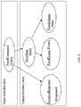
FIG. 3 is an architecture illustrating the components and flow of the system under consideration for identification of changes in the functional behavior and the runtime behavior during maintenance cycles (of the system under consideration) according to some embodiments of the present disclosure. -
FIGS. 4A and4B illustrate examples of system design comprising computer system concepts, structures and behavior corresponding to monitoring and control domain captured using a modeling language according to some embodiments of the present disclosure. -
FIG. 5 illustrates an example graphical representation of a design model or a first graph generated based upon the system design for identifying changes in the functional behavior and the runtime behavior of the system under consideration according to some embodiments of the present disclosure. -
FIG. 6A illustrates an example of an interaction graph comprising of direct and indirect interactions within a controller according to some embodiments of the present disclosure. -
FIG. 6B illustrates another example of the interaction graph comprising of the direct and indirect interactions across the controller according to some embodiments of the present disclosure. -
FIG. 7 illustrates an example of a set of implementation codes auto-generated based upon the system design according to some embodiments of the present disclosure. -
FIG. 8 illustrates an example of one or more models constructed based upon one or more log files according to some embodiments of the present disclosure. -
FIG. 9 shows a graphical representation of an operations model or a first graph generated based upon the system design for identifying changes in the functional behavior and the runtime behavior of the another system according to some embodiments of the present disclosure. -
FIG. 10 illustrates tracing of the one or more log files and updating the operations model table according to some embodiments of the present disclosure. -
FIG. 11 shows a graphical representation of a comparison between traditional methods and proposed disclosure with respect to time taken to identify changes in the system design for identifying changes in the functional behavior and the runtime behavior of the another system according to some embodiments of the present disclosure. -
FIG. 12 shows a graphical representation of the comparison between the traditional methods and the proposed disclosure with respect to percentage of success achieved by implementing the proposed disclosure in comparison with the traditional methods for identifying changes in the functional behavior and the runtime behavior of the another system according to some embodiments of the present disclosure. - The embodiments herein and the various features and advantageous details thereof are explained more fully with reference to the non-limiting embodiments that are illustrated in the accompanying drawings and detailed in the following description. The examples used herein are intended merely to facilitate an understanding of ways in which the embodiments herein may be practiced and to further enable those of skill in the art to practice the embodiments herein. Accordingly, the examples should not be construed as limiting the scope of the embodiments herein.
- The embodiments of the present disclosure provide systems and methods for identification of changes in functional behavior and runtime behavior of a system (that is another system comprising of a computing device, also hereinafter referred to as system under consideration) during maintenance cycles. A system undergoing maintenance is subject to a lot of behavioral and other changes. However, a change introduced into the system is mostly done by human and has to be manually traced back to the corresponding change in the design. Most computer systems cannot be completely verified before they are put in service. The high complexity of complete fielded systems places them beyond the reach of exhaustive formal analysis tools, such as model checkers and theorem provers. Furthermore, many systems rely on third-party components, for which a complete specification (or even source code) is not available. The traditional methods focus simply on manual modification of codes and over a period of time the associated design becomes obsolete due to lack of traceability.
- The traditional methods view the problem of change identification de-coupled from the system design, making the process further human dependent. As a result, the time and probability of error increases. Runtime verification permits checking system properties that cannot be fully verified off-line. This is particularly true when the system includes complex third-party components, such as general-purpose operating systems and software libraries, and when the properties of interest include security and performance. Runtime verification specifications are typically expressed in trace predicate formalisms, such as finite state machines, regular expressions, context-free patterns, linear temporal logics, etc., or extensions of these. This allows for a less ad-hoc approach than normal testing. However, any mechanism for monitoring an executing system is considered runtime verification, including verifying against test oracles and reference implementations. Some of the traditional methods provide for runtime verification but do not provide for an auto code generation and creating different views from the point of view of different stakeholders e.g., designer, developer, operations engineer etc.
- Hence, there is a need for a technology that provides for a change identification by viewing the system design from the operations viewpoint creating a common reference for the design and the operation. As the system executes, the logged execution details must be proactively validated by the methodology to check its consistency with the design. Further, the technology must provide as to how a strategy can be embedded into the code of the software system, by embedding loggers at problem places in the code, and thus providing for a pro-active monitoring of the system operations to monitor the system behavior execution.
- Referring now to the drawings, and more particularly to
FIG. 1 through FIG. 13 , where similar reference characters denote corresponding features consistently throughout the figures, there are shown preferred embodiments and these embodiments are described in the context of the following exemplary system and/or method. -
FIG. 1 illustrates an exemplary block diagram of asystem 100 for identification of changes in the functional behavior and the runtime behavior of the another system or the system under consideration, comprising of the computing device) during maintenance cycles according to an embodiment of the present disclosure. In an embodiment, thesystem 100 includes one ormore processors 104, communication interface device(s) or input/output (I/O) interface(s) 106, and one or more data storage devices ormemory 102 operatively coupled to the one ormore processors 104. The one ormore processors 104 that are hardware processors can be implemented as one or more microprocessors, microcomputers, microcontrollers, digital signal processors, central processing units, state machines, logic circuitries, and/or any devices that manipulate signals based on operational instructions. Among other capabilities, the processor(s) is configured to fetch and execute computer-readable instructions stored in the memory. In an embodiment, thesystem 100 can be implemented in a variety of computing systems, such as laptop computers, notebooks, hand-held devices, workstations, mainframe computers, servers, a network cloud and the like. - The I/O interface device(s) 106 can include a variety of software and hardware interfaces, for example, a web interface, a graphical user interface, and the like and can facilitate multiple communications within a wide variety of networks N/W and protocol types, including wired networks, for example, LAN, cable, etc., and wireless networks, such as WLAN, cellular, or satellite. In an embodiment, the I/O interface device(s) can include one or more ports for connecting a number of devices to one another or to another server.
- The
memory 102 may include any computer-readable medium known in the art including, for example, volatile memory, such as static random access memory (SRAM) and dynamic random access memory (DRAM), and/or non-volatile memory, such as read only memory (ROM), erasable programmable ROM, flash memories, hard disks, optical disks, and magnetic tapes. - In an embodiment, the another system (or the system under consideration) for which the methodology for identification of changes in the functional behavior and the runtime behavior has been proposed comprises of a computing device, wherein the computing device may be a computer system, laptop, keyboard etc. or any other computing device further comprising of all hardware and software components such as a memory, hardware processor/s, mouse, operating system, memory, peripheral devices etc. which are required to make the computing device capable of executing all tasks via a set of instructions, for example, programs. Further, the system on which the methodology for identification of changes in the functional behavior and the runtime behavior has been implemented and tested, which may be similar to or different from the
system 100 referred to in this disclosure. The term 'another system' refers to a system on which the proposed methodology has been implemented and tested (that is the system under consideration), which may be similar to or different from thesystem 100 referred to in this disclosure. The terms 'another system' and 'system under consideration' may be used interchangeably. -
FIG. 2A through 2B , with reference toFIG. 1 , illustrates an exemplary flow diagram of a method for identification of changes in the functional behavior and the runtime behavior of the system under consideration during maintenance cycles according to an embodiment of the present disclosure. In an embodiment thesystem 100 comprises one or more data storage devices of thememory 102 operatively coupled to the one ormore hardware processors 104 and is configured to store instructions for execution of steps of the method by the one ormore processors 104. The steps of the method of the present disclosure will now be explained with reference to the components of thesystem 100 as depicted inFIG. 1 and the flow diagram. In the embodiments of the present disclosure, thehardware processors 104 when configured the instructions performs one or more methodologies described herein. - According to an embodiment of the present disclosure, referring to
FIG. 3 , the architecture and components of the system under consideration for identification of changes in the functional behavior and the runtime behavior during maintenance cycles may be referred. Alog insertion component 301 update log files based upon a set of codes. Thelog insertion component 301 comprises of a listener (not shown in the figure) and the listener constantly checks the log files for any new entries in the log files. Alog monitoring component 302 keeps a track of the log files and extracts the execution details from log statements for an operation. Anoperations verification component 303 compares and two models (that is, a reference model and an actual model) identify changes in behavior (function and/or runtime) of the system under consideration. Further, in case of any mismatch of values between the operations model and the design model then theoperations verification component 303 notifies that the order of execution was not as expected although the behavior was valid. Acode generator 304 inserts the log statements into the framework codes as key-value pairs. - According to an embodiment of the present disclosure, at
step 201, the one ormore hardware processors 104 acquire, a system design, wherein the system design comprises computer system concepts, structures and behavior corresponding to monitoring and control domain. In an embodiment, the system design may be captured by the one ormore hardware processors 104 using a modeling language, for example, domain specific modeling language (DSML) like a Monitoring and Control Modeling Language (M&C ML). The DSML enables standardization of domain specific concepts, structures and behavior representations. The standardization ensures that the domain specific concepts, structures and behavior representations may be reused for solving similar computer system problems in Monitoring and Control domain. - In an example implementation, using the M&C ML, a design of supervisory control systems may be captured by the DSML. In an embodiment, the DSML is based upon Xtext (that is an open source software framework) and thus the DSML facilitates building of an Integrated Development Environment (IDE). In an embodiment, based upon the M&C ML DSML, the system design may be acquired the one or
more hardware processors 104. Referring toFIGS. 4A and4B , examples of the system design comprising of the computer system concepts, structures and behavior corresponding to the monitoring and control domain may be referred. - According to an embodiment of the present disclosure, at
step 202, based upon the system design, a design model may be constructed (discussed in paragraph 38), wherein the design model comprises a first set of neighborhood values corresponding to the functional behavior elements of the system design. According to an embodiment of the present disclosure, a design table (corresponding to the design model) may be auto-created based upon the system design and using the modeling language. The design table serves as a reference against which the monitored activity could be verified. In an embodiment, the design table may be represented as a graph, that is a first graph, wherein the functional flow of the system under consideration derived from the system design may be represented as the first graph G(V,E), and wherein vertices, referred to as a first set of input vertices and a first set of output vertices of the first graph comprise of one or more interface components. Further, edges of the first graph are functions connecting the first set of input vertices and the first set of output vertices. - In an embodiment, the first graph indicates a flow of the function execution of the system under consideration with the one or more interface components serving as one or more input vertices or one or more output vertices (also referred to as the first set of input vertices and the first set of output vertices). The one or more interface components may be connected to multiple interface components through multiple functions, wherein the multiple interface components comprise of a plurality of components (other than the one or more interface components). For example, referring to
FIG. 5 , an example of the first graph representing the design model may be referred, wherein an instance of the one or more interface components command, "COM1" is connected to the plurality of components (other than the one or more interface components), that is, "STATE1"," EVENT2" and "COM3". - In an example implementation, referring to
FIG. 5 again, it may be noted that "COM1" is the starting point or an input for the function "StateTransition" resulting into state "STATE1". Thus "STATE1" may be referred to as an output (or one or more output vertices) in the first set of output vertices. As discussed above, the first graph comprises of the one or more input vertices and the one or more output vertices. Hence ("COM1", "StateTransition", "STATE1") become a part of the functional flow. Similarly ("STATE1", "EntryAction", "EVENT2") and ("STATE1", "ExitAction", "COM3") are also branches of the functional flow of the system under consideration. Hence, it can be derived that the flow "COM1" -> "STATE1" -> EVENT2 comprises one of the paths that the system under consideration would be expected to execute during its operations. It may be noted that "StateTransition", "EntryAction", "ExitAction" etc form the edges of the first graph. Therefore, the edges in the first graph are the functions connecting the first set of input vertices and the first set of output vertices, and wherein the first graph indicates a flow of functional execution of the another system (or the system under consideration). - In an embodiment, referring to Table 1 below, an example of the design table auto-created based upon the system design and using the modeling language may be referred. In an embodiment, the design table as shown in Table 1 is created for an end to end path execution. An executing path may comprise of multiple sub-paths represented by the individual rows in Table 1. A sub-path comprises of an input indicated by the first column, an edge or function indicated in the first column and output indicated by the third column. The fourth column represents a set of design values, also called as the first set of neighborhood values, implying the distance between the inputs and the outputs. Thus, in an embodiment, the first set of neighborhood values comprise of a set of values generated based upon a distance between the first set of input vertices and the first set of output vertices in the first graph, and as discussed above, the vertices corresponding to the first graph further comprise of the one or more input vertices and the one or more output vertices.
- In an example implementation, referring to
FIG. 5 and Table 1 again below, it may be noted that the distance (that is, the first set of neighborhood values) between the first set of input vertices, that is, "COM1" and the first set of output vertices, that is, "STATE1" is 1. The distance between "COM1" and EVENT2 will be 2. Thus, immediate neighbors have distance of and it increases based on number of hops. This is done for all paths traversed within a controller as well as across the controllers. The embodiments of the present disclosure support creating similar tables for paths within and across the controllers. The design table stores the expected executions that could be monitored during runtime. The design table also serves as the reference against which the monitored activity could be verified. It thus provides a set of reference entities (comprising of the interface components and the first set of neighborhood values) by which actual design and intended design of the system under consideration may be compared. For example, referring to Table 1, it may be noted that that when "COM1" is fired, the functional execution would result into Response1.Table 1 Input Interface component Output Interface component Function First set of Neighborhood values Controller1.COM1 Command and Response Controller1.Response1 1 Controller1. COM1 Transition Controller 1. STATE 11 Controller1.COM1 Entry Action Controller1.Event1 2 - In an embodiment, the first graph is an interaction graph, and wherein an interaction may be a direct interaction or an indirect interaction depending upon a number of edges corresponding to a functions of edge in the interaction graph. Further, the first set of neighborhood values vary depending upon the direct interaction or the indirect interaction in the interaction graph. In an example implementation, referring to
FIG. 6A and 6B , example of the interaction graph comprising of the direct interaction and the indirect interaction may be referred, whereFIG. 6A corresponds to the direct interaction and the indirect interaction within a controller (not shown in the figure), whileFIG. 6B refers to the direct interaction and the indirect interaction across the controller. - In an embodiment, the interaction graph is populated for the controller. The Controller comprises of the one or more interface items like "Commands", "Events", "States", "State Machine etc". When a design for the controller is defined, the one or more interface components and their intended behavior (using the DSML) may be defined. When the design is specified for the controller, the design details may then be then converted into a design model corresponding to the controller.
- Referring to
FIG. 6A and 6B , again, the direct interaction, that is, when the one or more interface components interact via a single function, they become direct neighbors. For e.g. "COM1", "Response1" has a design value of 1 since they interact directly via "CommandResponse". This is an example of the direct interaction. Referring toFIG. 6A and 6B again, an example of the indirect interaction may be referred, that is, when the one or more interface components interact indirectly via multiple functions, (for example, "Event1" which is the indirect or second neighbor of "COM1" and thus has a Neighbor Value of 2. - According to an embodiments of the present disclosure, at
step 203, a set of implementation codes, based upon the system design may be auto-generated, wherein the set of implementation codes comprise, inter-alia, one or more framework based codes. In an embodiment, the system design captured using the M&C ML DSML may be translated into the set of implementation codes using a Domain Specific Engineering Environment (DSEE) framework. The set of implementation codes confirm to TANGO framework, an open source Supervisory control and data acquisition (SCADA) package. Further, as is known in the art, the TANGO conform to monitoring and control technology and domain. - In an example implementation, referring to
FIG. 7 , suppose the behavior for the command "START" captured in the system design using the DSML is converted into the design table. The details for input component Servo.START command exist in the design table. Thelog insertion component 301 checks if the component for which the code is generated (that is the command START) exists in the design table. Referring toFIG. 7 again, based upon the verification by thelog insertion component 301 that the command "START" exists, the set of implementation codes corresponding to the "START" command may be generated as below:
            @ Command(name=' START')
            public String START (String.STARTParams) throws DevFailed {xLogger. Entry();
            xLogger.info("COMMAND: : START")
            String STARTOut = null;
            /*.......PROTECTED REGION ID(SERVO_CN.START) ENABLED START
            if (getstate().equals(DevState.ON)) {
            setState(DevState.ON);
            deviceManager.pushEvent("STARTED",EventType.USER_EVENT);
            }
            //Put command code here
            xLogger.exit ();
            return StartOut;
            }
                                              Logging.txt
         INFO 2017-05-26 17:46:18,557 c.m.nj.Servo_CN.START:331 - COMMAND::START
                INFO 2017-05-26 17:46:18,558 c.m.nj.Servo-CN.getMnc_STATE:97 -
                                   CURRENT_STATE::OFF
                INFO 2017-05-26 17:46:18,558 c.m.n.j.Servo CN.setMnc_STATE:110 -
                                      NEXT_STATE::OFF
                INFO 2017-05-26 17:46:18,558 c.m.n.j.Servo_CN.setMnc_EVENT:134 -
                                      EVENT::STARTED
          INFO 2017-05-26 17:46:18,557 c.m.n.j.Servo_CN.STOP:365 - COMMAND::STOP
                INFO 2017-05-26 17:46:18,558 c.m.n.j.Servo_CN.getMnc_STATE:97 -
                                    CURRENT_STATE: :ON
                INFO 2017-05-26 17:46:18,558 c.m.n.j.Servo_CN.setMnc_STATE:110 -
                                      NEXT_STATE::OFF
                INFO 2017-05-26 17:46:18,558 c.m.n.j.Servo_CN.setMnc_EVENT:134 -
                                      EVENT: :STOPPED
| Input Interface component | Function | Output Interface component | Second set of Neighborhood values | |
| Servo.START | | SERVO.ON | 1 | |
| Servo.START | Entry Action | SERVO. STARTED | 2 |
| Input Interface component | Function | Output Interface component | Second set of Neighborhood values | |
| Servo. STOPPED | | SERVO.OFF | 1 | |
| Servo. STOPPED | Entry Action | SERVO.STOPPED | 2 |
| Input Interface component (A) | Output Interface component (B) | Neighborhood values (C) | |
| Controller1. | Controller1.Response1 | 1 | |
| Controller1. | Controller1.STATE1 | 1 | |
| Controller1. | Controller1.Event1 | 2 |
| Input Interface component (A) | Output Interface component (B) | Neighborhood values (C) | |
| Controller1. | Controller1.Response1 | 1 | |
| Controller1. | Controller1.STATE1 | 1 | |
| Controller1. | Controller1.Event1 | 2 |
The Alarm:-POWER_OUT was raised successfully while state transition Correct responseRES_DOMON was received from Command:DOMON
Command DOMON successfully validated against design objectives The transition from State:-START=>START is successfully operational
| Number of iterations (A) | Instances of design elements (B) | Resultant behavior elements of the system (C) | Modified design elements (D) | Number of other design elements modified (E) | Logs generated per iteration (F) |
| 1 | 10 | 10 | 4 | 7 | 13 |
| 2 | 15 | 14 | 2 | 4 | 28 |
| 3 | 20 | 17 | 6 | 13 | 46 |
| 4 | 26 | 16 | 6 | 12 | 23 |
| Time taken (in minutes) (A) | Number of queries created (B) | Changes identified (C) |
| 4 | 2 | 6 |
| 5 | 2 | 3 |
| 12 | 3 | 9 |
| 18 | 12 | 7 |
| Time taken (in minutes) (A) | Number of queries created (B) | Changes identified (C) |
| 0.001 | 0 | 7 |
| 0.001 | 0 | 4 |
| 0.001 | 0 | 13 |
| 0.001 | 0 | 12 |
Claims (15)
- A method for identification of changes in functional behavior and runtime behavior of a system during maintenance cycles, the method comprising a processor implemented steps of:acquiring, by one or more hardware processors, a system design, wherein the system design comprises computer system concepts, structures and behavior corresponding to monitoring and control domain;constructing, a design model, based upon the system design, wherein the design model comprises a first set of neighborhood values corresponding to the functional behavior elements of the system design;auto-generating, a set of implementation codes, based upon the design model and the system design, wherein the set of implementation codes comprise one or more framework based codes;performing, by the one or more hardware processors, a plurality of steps, based upon the set of implementation codes, wherein the plurality of steps comprise:(i) updating, using a log statement insertion component, a plurality of log statements into the set of implementation codes, wherein the plurality of log statements comprise information corresponding to the runtime behavior of the system; and(ii) populating, one or more log files, wherein the one or more log files comprise information corresponding to execution details of the system, and wherein the one or more log files are updated with the execution details using the plurality of log statements;constructing, one or more models, based upon the one or more log files, wherein the one or more models comprise of a set of information corresponding to the execution details of the system captured to derive a runtime view and operational details of the system;constructing, an operations model, based upon the one or more models, wherein the operations model comprises a second set of neighborhood values corresponding to the execution details of the system to compare actual and intended designs of the system; andcomparing, using an operations verification component, the operations model and a design table, to identify changes in the functional behavior and the runtime behavior of the system.
- The method of claim 1, wherein the second set of neighborhood values comprise of a set of values generated based upon a distance between a second set of input vertices and a second set of output vertices of the operations model represented in a second graph, wherein the second set of neighborhood values vary depending upon a direct interaction or an indirect interaction in an interaction graph.
- The method of claim 1, wherein the design table is auto-created based upon the system design and using a modeling language to generate a set of reference entities, and wherein the set of reference entities facilitate identification of changes in the runtime behavior of the system.
- The method of claim 1, wherein the design table is represented in a first graph comprising of a first set of input vertices and a first set of output vertices, wherein the first set of input vertices comprise of one or more interface components, wherein edges in the first graph are functions connecting the first set of input vertices and the first set of output vertices, and wherein the first graph indicates a flow of functional execution of the system.
- The method of claim 4, wherein the design table comprises of the first set of neighborhood values corresponding to the design model, wherein the first set of neighborhood values are generated based upon the system design for facilitating the comparison of the operations model and the design table, and wherein the first set of neighborhood values are further generated based upon a distance between the first set of input vertices and the first set of output vertices in the first graph.
- The method of claim 1, wherein the plurality of log statements are inserted into the one or more framework based codes as one or more key-value pairs by a code generator using the design table and wherein a key comprises one or more components corresponding to one or more interface components and a value is logged as a value corresponding to the key.
- The method of claim 1, wherein the operations model is updated based upon a set of executed functionalities corresponding to the system and the plurality of log statements inserted in the one or more log files to identify changes in the functional behavior and the runtime behavior of the system.
- The method of claim 4, wherein the first graph is an interaction graph, and wherein an interaction in the interaction graph comprises of a direct interaction or an indirect interaction depending upon a number of edges corresponding to a function of the edges in the interaction graph.
- A system comprising:a memory storing instructions;one or more communication interfaces; andone or more hardware processors coupled to the memory via the one or more communication interfaces, wherein the one or more hardware processors are configured by the instructions to:acquire, by the one or more hardware processors, a system design, wherein the system design comprises computer system concepts, structures and behavior corresponding to monitoring and control domain;construct, a design model, based upon the system design, wherein the design model comprises a first set of neighborhood values corresponding to functional behavior elements of the system design;auto-generate, a set of implementation codes, based upon the design model and the system design, wherein the set of implementation codes comprise one or more framework based codes;perform, by the one or more hardware processors, a plurality of steps, based upon the set of implementation codes, wherein the plurality of steps comprise:(i) update, using a log statement insertion component, a plurality of log statements into the set of implementation codes, wherein the plurality of log statements comprise information corresponding to runtime behavior of another system; and(ii)populate, one or more log files, wherein the one or more log files comprise information corresponding to execution details of the another system, and wherein the one or more log files are updated with the execution details using the plurality of log statements;construct, one or more models, based upon the one or more log files, wherein the one or more models comprise of a set of information corresponding to the execution details of the another system captured to derive a runtime view and operational details of the another system;construct, an operations model, based upon the one or more models, wherein the operations model comprises a second set of neighborhood values corresponding to the execution details of the another system to compare actual and intended designs of the another system; andcompare, using an operations verification component, the operations model and a design table, to identify changes in the functional behavior and the runtime behavior of the another system.
- The system of claim 9, wherein the second set of neighborhood values comprise of a set of values generated based upon a distance between a second set of input vertices and a second set of output vertices of the operations model represented in a second graph, wherein the second set of neighborhood values vary depending upon a direct interaction or an indirect interaction in an interaction graph.
- The system of claim 9, wherein the design table is auto-created based upon the system design and using a modeling language to generate a set of reference entities, and wherein the set of reference entities facilitate identification of changes in the runtime behavior of the another system.
- The system of claim 9, wherein the design table is represented in a first graph comprising of a first set of input vertices and a first set of output vertices, wherein the first set of input vertices comprise of one or more interface components, wherein edges in the first graph are functions connecting the first set of input vertices and the first set of output vertices, and wherein the first graph indicates a flow of functional execution of the another system, wherein the first graph is an interaction graph, and wherein an interaction in the interaction graph comprises of a direct interaction or an indirect interaction depending upon a number of edges corresponding to a function of the edges in the interaction graph.
- The system of claim 12, wherein the design table comprises of the first set of neighborhood values corresponding to the design model, wherein the first set of neighborhood values are generated based upon the system design for facilitating the comparison of the operations model and the design table, and wherein the first set of neighborhood values are further generated based upon a distance between the first set of input vertices and the first set of output vertices in the first graph.
- The system of claim 9, wherein the plurality of log statements are inserted into the one or more framework based codes as one or more key-value pairs by a code generator using the design table and wherein a key comprises one or more components corresponding to one or more interface components and a value is logged as a value corresponding to the key.
- The system of claim 9, wherein the operations model is updated based upon a set of executed functionalities corresponding to the system and the plurality of log statements inserted in the one or more log files to identify changes in the functional behavior and the runtime behavior of the another system.
Applications Claiming Priority (1)
| Application Number | Priority Date | Filing Date | Title |
|---|---|---|---|
| IN201821002775 | 2018-01-23 |
Publications (2)
| Publication Number | Publication Date |
|---|---|
| EP3514680A1 true EP3514680A1 (en) | 2019-07-24 |
| EP3514680B1 EP3514680B1 (en) | 2021-12-15 |
Family
ID=65041556
Family Applications (1)
| Application Number | Title | Priority Date | Filing Date |
|---|---|---|---|
| EP19150961.1A Active EP3514680B1 (en) | 2018-01-23 | 2019-01-09 | Identification of changes in functional behavior and runtime behavior of a system during maintenance cycles |
Country Status (2)
| Country | Link |
|---|---|
| US (1) | US11163924B2 (en) |
| EP (1) | EP3514680B1 (en) |
Families Citing this family (3)
| Publication number | Priority date | Publication date | Assignee | Title |
|---|---|---|---|---|
| JP2022527266A (en) * | 2019-03-25 | 2022-06-01 | オーロラ ラブズ リミテッド | Code line behavior and relational model generation and signature |
| EP3734460B1 (en) * | 2019-04-30 | 2021-10-27 | Hewlett Packard Enterprise Development LP | Probabilistic software testing via dynamic graphs |
| US20210182386A1 (en) * | 2019-12-11 | 2021-06-17 | Samsung Electronics Co., Ltd. | Electronic apparatus that monitors a safety function and a controlling method thereof |
Citations (3)
| Publication number | Priority date | Publication date | Assignee | Title |
|---|---|---|---|---|
| US20060168555A1 (en) * | 2005-01-21 | 2006-07-27 | Represas Ferrao Lucio E | Software development system and method |
| US20070006130A1 (en) * | 2005-06-02 | 2007-01-04 | Arnold Stamler | Model oriented method of automatically detecting alterations in the design of a software system |
| US7627671B1 (en) * | 2004-05-22 | 2009-12-01 | ClearApp, Inc. | Monitoring and performance management of component-based applications |
Family Cites Families (9)
| Publication number | Priority date | Publication date | Assignee | Title |
|---|---|---|---|---|
| US4364110A (en) | 1970-12-28 | 1982-12-14 | Hyatt Gilbert P | Computerized machine control system |
| US6076180A (en) * | 1997-06-23 | 2000-06-13 | Micron Electronics, Inc. | Method for testing a controller with random constraints |
| US6453450B1 (en) | 2000-02-02 | 2002-09-17 | International Business Machines Corporation | Timing diagram compiler and runtime environment for interactive generation of executable test programs for logic verification |
| US7174534B2 (en) * | 2001-01-22 | 2007-02-06 | Symbol Technologies, Inc. | Efficient system and method for running and analyzing multi-channel, multi-modal applications |
| US6859893B2 (en) * | 2001-08-01 | 2005-02-22 | Sun Microsystems, Inc. | Service guru system and method for automated proactive and reactive computer system analysis |
| US20060023638A1 (en) | 2004-07-29 | 2006-02-02 | Solutions4Networks | Proactive network analysis system |
| US7386827B1 (en) * | 2006-06-08 | 2008-06-10 | Xilinx, Inc. | Building a simulation environment for a design block |
| US8255191B1 (en) * | 2009-04-30 | 2012-08-28 | Cadence Design Systems, Inc. | Using real value models in simulation of analog and mixed-signal systems |
| US10635843B2 (en) * | 2015-06-04 | 2020-04-28 | Synopsys, Inc. | Simulation modeling frameworks for controller designs |
-
2019
- 2019-01-09 EP EP19150961.1A patent/EP3514680B1/en active Active
- 2019-01-11 US US16/246,245 patent/US11163924B2/en active Active
Patent Citations (3)
| Publication number | Priority date | Publication date | Assignee | Title |
|---|---|---|---|---|
| US7627671B1 (en) * | 2004-05-22 | 2009-12-01 | ClearApp, Inc. | Monitoring and performance management of component-based applications |
| US20060168555A1 (en) * | 2005-01-21 | 2006-07-27 | Represas Ferrao Lucio E | Software development system and method |
| US20070006130A1 (en) * | 2005-06-02 | 2007-01-04 | Arnold Stamler | Model oriented method of automatically detecting alterations in the design of a software system |
Also Published As
| Publication number | Publication date |
|---|---|
| US11163924B2 (en) | 2021-11-02 |
| EP3514680B1 (en) | 2021-12-15 |
| US20190236223A1 (en) | 2019-08-01 |
Similar Documents
| Publication | Publication Date | Title |
|---|---|---|
| US11494295B1 (en) | Automated software bug discovery and assessment | |
| US8782609B2 (en) | Test failure bucketing | |
| Xu et al. | POD-Diagnosis: Error diagnosis of sporadic operations on cloud applications | |
| EP3514680B1 (en) | Identification of changes in functional behavior and runtime behavior of a system during maintenance cycles | |
| US20100299654A1 (en) | Approach for root causing regression bugs | |
| CN110704297B (en) | Code review method, device, computer equipment and storage medium | |
| CN108491321B (en) | Method and device for determining test case range and storage medium | |
| CN111382070B (en) | Compatibility testing method and device, storage medium and computer equipment | |
| CN111258591B (en) | Program deployment task execution method, device, computer equipment and storage medium | |
| CN111108481B (en) | Fault analysis method and related equipment | |
| CN113282513B (en) | Interface test case generation method and device, computer equipment and storage medium | |
| CN112561370A (en) | Software version management method and device, computer equipment and storage medium | |
| CN107357619B (en) | Method, device, equipment and storage medium for generating card configuration file | |
| US9612944B2 (en) | Method and system for verifying scenario based test selection, execution and reporting | |
| US20190073292A1 (en) | State machine software tester | |
| US11645192B2 (en) | Graph-based method for inductive bug localization | |
| CN117493188A (en) | Interface testing method and device, electronic equipment and storage medium | |
| CN112256532A (en) | Test interface generation method and device, computer equipment and readable storage medium | |
| CN105577424A (en) | Data asset quality monitoring method based on data traceability graph | |
| CN115658482A (en) | Database testing method and device, electronic equipment and computer readable storage medium | |
| CN113051582B (en) | Computer software technology development and debugging system | |
| CN115454860A (en) | Automatic testing method and device, storage medium and electronic equipment | |
| CN111045891B (en) | Monitoring method, device, equipment and storage medium based on java multithreading | |
| US20200391885A1 (en) | Methods and systems for identifying aircraft faults | |
| CN115705297A (en) | Code call detection method, device, computer equipment and storage medium |
Legal Events
| Date | Code | Title | Description |
|---|---|---|---|
| PUAI | Public reference made under article 153(3) epc to a published international application that has entered the european phase |
Free format text: ORIGINAL CODE: 0009012 |
|
| STAA | Information on the status of an ep patent application or granted ep patent |
Free format text: STATUS: THE APPLICATION HAS BEEN PUBLISHED |
|
| AK | Designated contracting states |
Kind code of ref document: A1 Designated state(s): AL AT BE BG CH CY CZ DE DK EE ES FI FR GB GR HR HU IE IS IT LI LT LU LV MC MK MT NL NO PL PT RO RS SE SI SK SM TR |
|
| AX | Request for extension of the european patent |
Extension state: BA ME |
|
| STAA | Information on the status of an ep patent application or granted ep patent |
Free format text: STATUS: REQUEST FOR EXAMINATION WAS MADE |
|
| 17P | Request for examination filed |
Effective date: 20200124 |
|
| RBV | Designated contracting states (corrected) |
Designated state(s): AL AT BE BG CH CY CZ DE DK EE ES FI FR GB GR HR HU IE IS IT LI LT LU LV MC MK MT NL NO PL PT RO RS SE SI SK SM TR |
|
| GRAP | Despatch of communication of intention to grant a patent |
Free format text: ORIGINAL CODE: EPIDOSNIGR1 |
|
| STAA | Information on the status of an ep patent application or granted ep patent |
Free format text: STATUS: GRANT OF PATENT IS INTENDED |
|
| INTG | Intention to grant announced |
Effective date: 20210625 |
|
| GRAS | Grant fee paid |
Free format text: ORIGINAL CODE: EPIDOSNIGR3 |
|
| GRAA | (expected) grant |
Free format text: ORIGINAL CODE: 0009210 |
|
| STAA | Information on the status of an ep patent application or granted ep patent |
Free format text: STATUS: THE PATENT HAS BEEN GRANTED |
|
| AK | Designated contracting states |
Kind code of ref document: B1 Designated state(s): AL AT BE BG CH CY CZ DE DK EE ES FI FR GB GR HR HU IE IS IT LI LT LU LV MC MK MT NL NO PL PT RO RS SE SI SK SM TR |
|
| REG | Reference to a national code |
Ref country code: GB Ref legal event code: FG4D Ref country code: CH Ref legal event code: EP |
|
| REG | Reference to a national code |
Ref country code: DE Ref legal event code: R096 Ref document number: 602019009974 Country of ref document: DE |
|
| REG | Reference to a national code |
Ref country code: IE Ref legal event code: FG4D |
|
| REG | Reference to a national code |
Ref country code: AT Ref legal event code: REF Ref document number: 1455987 Country of ref document: AT Kind code of ref document: T Effective date: 20220115 |
|
| REG | Reference to a national code |
Ref country code: NL Ref legal event code: FP |
|
| REG | Reference to a national code |
Ref country code: LT Ref legal event code: MG9D |
|
| PG25 | Lapsed in a contracting state [announced via postgrant information from national office to epo] |
Ref country code: RS Free format text: LAPSE BECAUSE OF FAILURE TO SUBMIT A TRANSLATION OF THE DESCRIPTION OR TO PAY THE FEE WITHIN THE PRESCRIBED TIME-LIMIT Effective date: 20211215 Ref country code: LT Free format text: LAPSE BECAUSE OF FAILURE TO SUBMIT A TRANSLATION OF THE DESCRIPTION OR TO PAY THE FEE WITHIN THE PRESCRIBED TIME-LIMIT Effective date: 20211215 Ref country code: FI Free format text: LAPSE BECAUSE OF FAILURE TO SUBMIT A TRANSLATION OF THE DESCRIPTION OR TO PAY THE FEE WITHIN THE PRESCRIBED TIME-LIMIT Effective date: 20211215 Ref country code: BG Free format text: LAPSE BECAUSE OF FAILURE TO SUBMIT A TRANSLATION OF THE DESCRIPTION OR TO PAY THE FEE WITHIN THE PRESCRIBED TIME-LIMIT Effective date: 20220315 |
|
| REG | Reference to a national code |
Ref country code: AT Ref legal event code: MK05 Ref document number: 1455987 Country of ref document: AT Kind code of ref document: T Effective date: 20211215 |
|
| PG25 | Lapsed in a contracting state [announced via postgrant information from national office to epo] |
Ref country code: SE Free format text: LAPSE BECAUSE OF FAILURE TO SUBMIT A TRANSLATION OF THE DESCRIPTION OR TO PAY THE FEE WITHIN THE PRESCRIBED TIME-LIMIT Effective date: 20211215 Ref country code: NO Free format text: LAPSE BECAUSE OF FAILURE TO SUBMIT A TRANSLATION OF THE DESCRIPTION OR TO PAY THE FEE WITHIN THE PRESCRIBED TIME-LIMIT Effective date: 20220315 Ref country code: LV Free format text: LAPSE BECAUSE OF FAILURE TO SUBMIT A TRANSLATION OF THE DESCRIPTION OR TO PAY THE FEE WITHIN THE PRESCRIBED TIME-LIMIT Effective date: 20211215 Ref country code: HR Free format text: LAPSE BECAUSE OF FAILURE TO SUBMIT A TRANSLATION OF THE DESCRIPTION OR TO PAY THE FEE WITHIN THE PRESCRIBED TIME-LIMIT Effective date: 20211215 Ref country code: GR Free format text: LAPSE BECAUSE OF FAILURE TO SUBMIT A TRANSLATION OF THE DESCRIPTION OR TO PAY THE FEE WITHIN THE PRESCRIBED TIME-LIMIT Effective date: 20220316 |
|
| PG25 | Lapsed in a contracting state [announced via postgrant information from national office to epo] |
Ref country code: SM Free format text: LAPSE BECAUSE OF FAILURE TO SUBMIT A TRANSLATION OF THE DESCRIPTION OR TO PAY THE FEE WITHIN THE PRESCRIBED TIME-LIMIT Effective date: 20211215 Ref country code: SK Free format text: LAPSE BECAUSE OF FAILURE TO SUBMIT A TRANSLATION OF THE DESCRIPTION OR TO PAY THE FEE WITHIN THE PRESCRIBED TIME-LIMIT Effective date: 20211215 Ref country code: RO Free format text: LAPSE BECAUSE OF FAILURE TO SUBMIT A TRANSLATION OF THE DESCRIPTION OR TO PAY THE FEE WITHIN THE PRESCRIBED TIME-LIMIT Effective date: 20211215 Ref country code: PT Free format text: LAPSE BECAUSE OF FAILURE TO SUBMIT A TRANSLATION OF THE DESCRIPTION OR TO PAY THE FEE WITHIN THE PRESCRIBED TIME-LIMIT Effective date: 20220418 Ref country code: ES Free format text: LAPSE BECAUSE OF FAILURE TO SUBMIT A TRANSLATION OF THE DESCRIPTION OR TO PAY THE FEE WITHIN THE PRESCRIBED TIME-LIMIT Effective date: 20211215 Ref country code: EE Free format text: LAPSE BECAUSE OF FAILURE TO SUBMIT A TRANSLATION OF THE DESCRIPTION OR TO PAY THE FEE WITHIN THE PRESCRIBED TIME-LIMIT Effective date: 20211215 Ref country code: CZ Free format text: LAPSE BECAUSE OF FAILURE TO SUBMIT A TRANSLATION OF THE DESCRIPTION OR TO PAY THE FEE WITHIN THE PRESCRIBED TIME-LIMIT Effective date: 20211215 |
|
| PG25 | Lapsed in a contracting state [announced via postgrant information from national office to epo] |
Ref country code: PL Free format text: LAPSE BECAUSE OF FAILURE TO SUBMIT A TRANSLATION OF THE DESCRIPTION OR TO PAY THE FEE WITHIN THE PRESCRIBED TIME-LIMIT Effective date: 20211215 Ref country code: AT Free format text: LAPSE BECAUSE OF FAILURE TO SUBMIT A TRANSLATION OF THE DESCRIPTION OR TO PAY THE FEE WITHIN THE PRESCRIBED TIME-LIMIT Effective date: 20211215 |
|
| REG | Reference to a national code |
Ref country code: DE Ref legal event code: R097 Ref document number: 602019009974 Country of ref document: DE |
|
| PG25 | Lapsed in a contracting state [announced via postgrant information from national office to epo] |
Ref country code: MC Free format text: LAPSE BECAUSE OF FAILURE TO SUBMIT A TRANSLATION OF THE DESCRIPTION OR TO PAY THE FEE WITHIN THE PRESCRIBED TIME-LIMIT Effective date: 20211215 Ref country code: IS Free format text: LAPSE BECAUSE OF FAILURE TO SUBMIT A TRANSLATION OF THE DESCRIPTION OR TO PAY THE FEE WITHIN THE PRESCRIBED TIME-LIMIT Effective date: 20220415 |
|
| REG | Reference to a national code |
Ref country code: BE Ref legal event code: MM Effective date: 20220131 |
|
| PLBE | No opposition filed within time limit |
Free format text: ORIGINAL CODE: 0009261 |
|
| STAA | Information on the status of an ep patent application or granted ep patent |
Free format text: STATUS: NO OPPOSITION FILED WITHIN TIME LIMIT |
|
| PG25 | Lapsed in a contracting state [announced via postgrant information from national office to epo] |
Ref country code: LU Free format text: LAPSE BECAUSE OF NON-PAYMENT OF DUE FEES Effective date: 20220109 Ref country code: DK Free format text: LAPSE BECAUSE OF FAILURE TO SUBMIT A TRANSLATION OF THE DESCRIPTION OR TO PAY THE FEE WITHIN THE PRESCRIBED TIME-LIMIT Effective date: 20211215 Ref country code: AL Free format text: LAPSE BECAUSE OF FAILURE TO SUBMIT A TRANSLATION OF THE DESCRIPTION OR TO PAY THE FEE WITHIN THE PRESCRIBED TIME-LIMIT Effective date: 20211215 |
|
| 26N | No opposition filed |
Effective date: 20220916 |
|
| PG25 | Lapsed in a contracting state [announced via postgrant information from national office to epo] |
Ref country code: SI Free format text: LAPSE BECAUSE OF FAILURE TO SUBMIT A TRANSLATION OF THE DESCRIPTION OR TO PAY THE FEE WITHIN THE PRESCRIBED TIME-LIMIT Effective date: 20211215 Ref country code: BE Free format text: LAPSE BECAUSE OF NON-PAYMENT OF DUE FEES Effective date: 20220131 |
|
| PG25 | Lapsed in a contracting state [announced via postgrant information from national office to epo] |
Ref country code: IE Free format text: LAPSE BECAUSE OF NON-PAYMENT OF DUE FEES Effective date: 20220109 |
|
| PGFP | Annual fee paid to national office [announced via postgrant information from national office to epo] |
Ref country code: FR Payment date: 20221221 Year of fee payment: 5 |
|
| PGFP | Annual fee paid to national office [announced via postgrant information from national office to epo] |
Ref country code: CH Payment date: 20230104 Year of fee payment: 5 |
|
| PG25 | Lapsed in a contracting state [announced via postgrant information from national office to epo] |
Ref country code: IT Free format text: LAPSE BECAUSE OF FAILURE TO SUBMIT A TRANSLATION OF THE DESCRIPTION OR TO PAY THE FEE WITHIN THE PRESCRIBED TIME-LIMIT Effective date: 20211215 |
|
| PGFP | Annual fee paid to national office [announced via postgrant information from national office to epo] |
Ref country code: DE Payment date: 20230131 Year of fee payment: 5 |
|
| P01 | Opt-out of the competence of the unified patent court (upc) registered |
Effective date: 20230526 |
|
| PGFP | Annual fee paid to national office [announced via postgrant information from national office to epo] |
Ref country code: NL Payment date: 20240125 Year of fee payment: 6 |
|
| PG25 | Lapsed in a contracting state [announced via postgrant information from national office to epo] |
Ref country code: MK Free format text: LAPSE BECAUSE OF FAILURE TO SUBMIT A TRANSLATION OF THE DESCRIPTION OR TO PAY THE FEE WITHIN THE PRESCRIBED TIME-LIMIT Effective date: 20211215 Ref country code: CY Free format text: LAPSE BECAUSE OF FAILURE TO SUBMIT A TRANSLATION OF THE DESCRIPTION OR TO PAY THE FEE WITHIN THE PRESCRIBED TIME-LIMIT Effective date: 20211215 |
|
| PGFP | Annual fee paid to national office [announced via postgrant information from national office to epo] |
Ref country code: DE Payment date: 20240129 Year of fee payment: 6 Ref country code: GB Payment date: 20240123 Year of fee payment: 6 Ref country code: CH Payment date: 20240201 Year of fee payment: 6 |