EP3502893A1 - Distributed lifecycle management for cloud platforms - Google Patents
Distributed lifecycle management for cloud platforms Download PDFInfo
- Publication number
- EP3502893A1 EP3502893A1 EP18213983.2A EP18213983A EP3502893A1 EP 3502893 A1 EP3502893 A1 EP 3502893A1 EP 18213983 A EP18213983 A EP 18213983A EP 3502893 A1 EP3502893 A1 EP 3502893A1
- Authority
- EP
- European Patent Office
- Prior art keywords
- cloud platform
- node
- nodes
- platform
- automatically
- Prior art date
- Legal status (The legal status is an assumption and is not a legal conclusion. Google has not performed a legal analysis and makes no representation as to the accuracy of the status listed.)
- Granted
Links
- 230000004044 response Effects 0.000 claims abstract description 40
- 238000012423 maintenance Methods 0.000 claims description 59
- 238000000034 method Methods 0.000 claims description 33
- 230000009471 action Effects 0.000 claims description 29
- 230000008859 change Effects 0.000 claims description 11
- 238000012544 monitoring process Methods 0.000 claims description 10
- 230000004913 activation Effects 0.000 claims description 4
- 230000008569 process Effects 0.000 description 29
- 238000000370 laser capture micro-dissection Methods 0.000 description 18
- 238000003860 storage Methods 0.000 description 13
- 238000013459 approach Methods 0.000 description 10
- 230000003287 optical effect Effects 0.000 description 9
- 238000005304 joining Methods 0.000 description 8
- 230000000737 periodic effect Effects 0.000 description 8
- 230000036541 health Effects 0.000 description 5
- 230000007246 mechanism Effects 0.000 description 5
- 230000000246 remedial effect Effects 0.000 description 5
- 238000013515 script Methods 0.000 description 5
- 230000007704 transition Effects 0.000 description 5
- 238000010586 diagram Methods 0.000 description 4
- 230000006870 function Effects 0.000 description 4
- 238000010397 one-hybrid screening Methods 0.000 description 4
- 230000010354 integration Effects 0.000 description 3
- 238000010399 three-hybrid screening Methods 0.000 description 3
- 230000002093 peripheral effect Effects 0.000 description 2
- 238000005067 remediation Methods 0.000 description 2
- 238000013341 scale-up Methods 0.000 description 2
- 230000003213 activating effect Effects 0.000 description 1
- 230000002411 adverse Effects 0.000 description 1
- 238000003491 array Methods 0.000 description 1
- 238000013475 authorization Methods 0.000 description 1
- 239000003795 chemical substances by application Substances 0.000 description 1
- 239000003818 cinder Substances 0.000 description 1
- 238000004891 communication Methods 0.000 description 1
- 238000004590 computer program Methods 0.000 description 1
- 239000000470 constituent Substances 0.000 description 1
- 238000013461 design Methods 0.000 description 1
- 238000003745 diagnosis Methods 0.000 description 1
- 238000009826 distribution Methods 0.000 description 1
- 238000005516 engineering process Methods 0.000 description 1
- 230000003862 health status Effects 0.000 description 1
- 239000000463 material Substances 0.000 description 1
- 230000002085 persistent effect Effects 0.000 description 1
- 238000012545 processing Methods 0.000 description 1
- 238000001338 self-assembly Methods 0.000 description 1
- 239000007787 solid Substances 0.000 description 1
Images


Classifications
-
- H—ELECTRICITY
- H04—ELECTRIC COMMUNICATION TECHNIQUE
- H04L—TRANSMISSION OF DIGITAL INFORMATION, e.g. TELEGRAPHIC COMMUNICATION
- H04L41/00—Arrangements for maintenance, administration or management of data switching networks, e.g. of packet switching networks
- H04L41/08—Configuration management of networks or network elements
- H04L41/0803—Configuration setting
- H04L41/0806—Configuration setting for initial configuration or provisioning, e.g. plug-and-play
-
- G—PHYSICS
- G06—COMPUTING; CALCULATING OR COUNTING
- G06F—ELECTRIC DIGITAL DATA PROCESSING
- G06F9/00—Arrangements for program control, e.g. control units
- G06F9/06—Arrangements for program control, e.g. control units using stored programs, i.e. using an internal store of processing equipment to receive or retain programs
- G06F9/44—Arrangements for executing specific programs
- G06F9/455—Emulation; Interpretation; Software simulation, e.g. virtualisation or emulation of application or operating system execution engines
- G06F9/45533—Hypervisors; Virtual machine monitors
- G06F9/45558—Hypervisor-specific management and integration aspects
-
- G—PHYSICS
- G06—COMPUTING; CALCULATING OR COUNTING
- G06F—ELECTRIC DIGITAL DATA PROCESSING
- G06F9/00—Arrangements for program control, e.g. control units
- G06F9/06—Arrangements for program control, e.g. control units using stored programs, i.e. using an internal store of processing equipment to receive or retain programs
- G06F9/46—Multiprogramming arrangements
- G06F9/50—Allocation of resources, e.g. of the central processing unit [CPU]
- G06F9/5005—Allocation of resources, e.g. of the central processing unit [CPU] to service a request
- G06F9/5027—Allocation of resources, e.g. of the central processing unit [CPU] to service a request the resource being a machine, e.g. CPUs, Servers, Terminals
- G06F9/5055—Allocation of resources, e.g. of the central processing unit [CPU] to service a request the resource being a machine, e.g. CPUs, Servers, Terminals considering software capabilities, i.e. software resources associated or available to the machine
-
- G—PHYSICS
- G06—COMPUTING; CALCULATING OR COUNTING
- G06F—ELECTRIC DIGITAL DATA PROCESSING
- G06F9/00—Arrangements for program control, e.g. control units
- G06F9/06—Arrangements for program control, e.g. control units using stored programs, i.e. using an internal store of processing equipment to receive or retain programs
- G06F9/46—Multiprogramming arrangements
- G06F9/50—Allocation of resources, e.g. of the central processing unit [CPU]
- G06F9/5061—Partitioning or combining of resources
- G06F9/5072—Grid computing
-
- G—PHYSICS
- G06—COMPUTING; CALCULATING OR COUNTING
- G06F—ELECTRIC DIGITAL DATA PROCESSING
- G06F9/00—Arrangements for program control, e.g. control units
- G06F9/06—Arrangements for program control, e.g. control units using stored programs, i.e. using an internal store of processing equipment to receive or retain programs
- G06F9/46—Multiprogramming arrangements
- G06F9/50—Allocation of resources, e.g. of the central processing unit [CPU]
- G06F9/5061—Partitioning or combining of resources
- G06F9/5077—Logical partitioning of resources; Management or configuration of virtualized resources
-
- H—ELECTRICITY
- H04—ELECTRIC COMMUNICATION TECHNIQUE
- H04L—TRANSMISSION OF DIGITAL INFORMATION, e.g. TELEGRAPHIC COMMUNICATION
- H04L67/00—Network arrangements or protocols for supporting network services or applications
- H04L67/01—Protocols
- H04L67/10—Protocols in which an application is distributed across nodes in the network
-
- H—ELECTRICITY
- H04—ELECTRIC COMMUNICATION TECHNIQUE
- H04L—TRANSMISSION OF DIGITAL INFORMATION, e.g. TELEGRAPHIC COMMUNICATION
- H04L67/00—Network arrangements or protocols for supporting network services or applications
- H04L67/34—Network arrangements or protocols for supporting network services or applications involving the movement of software or configuration parameters
-
- G—PHYSICS
- G06—COMPUTING; CALCULATING OR COUNTING
- G06F—ELECTRIC DIGITAL DATA PROCESSING
- G06F9/00—Arrangements for program control, e.g. control units
- G06F9/06—Arrangements for program control, e.g. control units using stored programs, i.e. using an internal store of processing equipment to receive or retain programs
- G06F9/44—Arrangements for executing specific programs
- G06F9/455—Emulation; Interpretation; Software simulation, e.g. virtualisation or emulation of application or operating system execution engines
- G06F9/45533—Hypervisors; Virtual machine monitors
- G06F9/45558—Hypervisor-specific management and integration aspects
- G06F2009/45562—Creating, deleting, cloning virtual machine instances
-
- G—PHYSICS
- G06—COMPUTING; CALCULATING OR COUNTING
- G06F—ELECTRIC DIGITAL DATA PROCESSING
- G06F9/00—Arrangements for program control, e.g. control units
- G06F9/06—Arrangements for program control, e.g. control units using stored programs, i.e. using an internal store of processing equipment to receive or retain programs
- G06F9/44—Arrangements for executing specific programs
- G06F9/455—Emulation; Interpretation; Software simulation, e.g. virtualisation or emulation of application or operating system execution engines
- G06F9/45533—Hypervisors; Virtual machine monitors
- G06F9/45558—Hypervisor-specific management and integration aspects
- G06F2009/4557—Distribution of virtual machine instances; Migration and load balancing
Definitions
- a cloud platform is a distributed computing system (computing cluster) that is to dynamically provide cloud services.
- the cloud platform is formed by a runtime instance of a cloud platform application and underlying hardware infrastructure.
- an operating system image is an image (e.g., disk image) that includes artifacts to control operations of a node.
- a service is a functionality or group of functionalities of a cloud platform.
- services may include an API service, a domain name system service, a scheduler services, a distributed key value store service, a platform worker (aka slave or minion) service, and so on.
- day-to-day maintenance tasks and failures require manual diagnosis and intervention by an IT professional.
- scaling the system after initial deployment is not supported in some approaches, or in other approaches is achieved via a manual reconfiguration of nodes by an IT professional.
- the cloud platform may be deployed by providing a set of the aforementioned intelligent nodes and instructing one of the nodes to begin self-assembling the platform.
- This first node may establish a cloud platform with itself as the sole member, and automatically invite the other nodes into the platform.
- its LCM may automatically determine how the node should be configured to provide a best possible platform.
- the LCMs of the nodes may coordinate with one another via a distributed decision making process, to ensure that a desired overall configuration of the platform is achieved.
- the LCMs may identify which roles the platform currently needs based on a desired end-state (e.g., a specified fault tolerance) and the currently available resources, and may determine which nodes should play which roles.
- a desired end-state e.g., a specified fault tolerance
- the LCMs of the nodes may automatically perform maintenance for the platform, including, for example, identifying and performing periodic platform maintenance tasks, identifying and remediating failures, etc.
- each node's LCM may monitor the status of the system, and, in response to a failure event (such as the failure of a service) that might require a remediation action (such as restarting the service on another node), the LCMs of the nodes may decide via distributed decision making which node should take the action.
- a failure event such as the failure of a service
- a remediation action such as restarting the service on another node
- the LCMs of the nodes may decide via distributed decision making which node should take the action.
- each node's LCM may monitor a platform maintenance task queue, and the LCMs of the nodes may decide via distributed decision making which node should perform which platform maintenance task.
- the nodes form a cooperative system, in which control over the configuration of the system (both initial, and ongoing) is distributed among the nodes (via their LCMs).
- control over the configuration of the system is distributed among the nodes (via their LCMs).
- configuration of the nodes is controlled in a top-down manner by a master entity, such as a configuration management master.
- a master entity such as a configuration management master.
- the examples described herein provide for a system that is essentially self-deploying and self-sustaining, can dynamically scale up or down (from a single node to many nodes), and can tolerate the failure of any node and remediate those failures without outside intervention.
- each node 40 is a computing device (virtualized or physical) that includes at least one processor 41 (virtualized or physical) capable of executing instructions stored on a non-transitory machine readable medium, such as memory 42 (virtualized or physical).
- the nodes 40 may also include a storage volume 43 (virtualized or physical) that may persistently store data for the node 40.
- the nodes 40 may also include additional components (virtual or physical), such as input/output units, controllers, peripherals, storage devices, etc.
- a node 40 may be a virtual machine (VM), a server, a blade of a blade server system, a compute module of a composable infrastructure appliance, a compute node of a converged (or hyperconverged) appliance, a compute node of a rack-scale system, a system-on-chip (SoC), a personal computer, a printed circuit board containing a processor, etc.
- VM virtual machine
- server a blade of a blade server system
- a compute module of a composable infrastructure appliance a compute node of a converged (or hyperconverged) appliance
- SoC system-on-chip
- personal computer a printed circuit board containing a processor, etc.
- the LCM 500 identifies a role that it thinks its node 40 should adopt in the cloud platform 100.
- the LCM 500 may identify, based on the current state of the platform 100 (as determined from the DKVS 30) and a desired configuration for the platform 100, which role the node 40 should be configured to adopt so as to most improve the state of the cloud platform 100. Additional details of how a node 40 may identify such a role for itself are described below.
- a fourth node 40-4 joins the platform 100.
- the fourth node 40-4 may determine that a desired platform-level configuration for the platform 100 in this state is to have three hybrid manager-worker nodes 40 and one worker-only node 40 (e.g., to provide high availability). Based on this desired configuration, the fourth node 40-4 may determine that it should become a worker-only, since this will improve the platform 100 by bringing the platform 100 closer to the desired configuration.
- the node 40 obtains the available lock for the role, whereupon the node 40 starts a process of automatically reconfiguring itself to adopt the role, for example by executing automated configuration scripts associated with the role.
- the condition giving rise to the task may be detected by any one of the LCMs 500 by monitoring the status of the platform 100.
- the status of the platform 100 may include both the configuration of the platform 100 (e.g., how many nodes, what roles the nodes are assigned, what services are activated and on which nodes, etc.), and the health of the platform 100 (e.g., are any nodes or services experiencing errors or failures or otherwise unhealthy).
- the LCM 500 may still check the DKVS 30 in block 617 to verify that the task is included in the task queue, and if not the LCM 500 may post the task to the task queue.
- Fig. 8 illustrates example processor executable instructions stored on a non-transitory machine readable medium 5000.
- lifecycle manager (LCM) program instructions 501 are stored on the medium 5000.
- the determining which services of the cloud platform 100 to activate on the respective node 40 includes automatically: identifying a role for the respective node 40 based on the current configuration of the second cloud platform 100, and selecting for activation those services of the cloud platform 100 that are associated with the identified role.
Landscapes
- Engineering & Computer Science (AREA)
- Software Systems (AREA)
- Theoretical Computer Science (AREA)
- Physics & Mathematics (AREA)
- General Engineering & Computer Science (AREA)
- General Physics & Mathematics (AREA)
- Computer Networks & Wireless Communication (AREA)
- Signal Processing (AREA)
- Mathematical Physics (AREA)
- Debugging And Monitoring (AREA)
- Management, Administration, Business Operations System, And Electronic Commerce (AREA)
- Information Retrieval, Db Structures And Fs Structures Therefor (AREA)
- User Interface Of Digital Computer (AREA)
- Stored Programmes (AREA)
Abstract
Description
- Cloud platforms may be used to provide cloud services to clients. A cloud platform is formed by a cloud platform application being run on underlying hardware infrastructure. Cloud services include, for example, Software-as-a-Service (SaaS), Platform-as-a-Service (PaaS), Infrastructure as a Service (laaS), and so on.
-
-
Fig. 1 illustrates an example of a deployed cloud platform. -
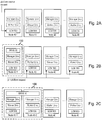
Figs. 2A-3C illustrate example cloud platforms at various stages of deployment. Specifically,Fig. 2A illustrates an initial deployment stage in which the nodes are in a ready state.Fig. 2B illustrates a second deployment stage, in which the cloud platform has one member node.Fig. 2C illustrates a third deployment stage, in which a second member node has been integrated into the cloud platform.Fig. 3A illustrates fourth deployment stage in which the cloud platform includes three member nodes.Fig. 3B illustrates a fifth deployment stage in which the cloud platform includes more than three member nodes.Fig. 3C illustrates a sixth deployment stage in which the cloud platform includes N member nodes. -
Fig. 4 is a process flow diagram illustrating an example process for initial setup of a platform setup. -
Fig. 5 is a process flow diagram illustrating an example process for integrating into a cloud platform. -
Fig. 6 is a process flow diagram illustrating an example process for responding to a scaling event. -
Fig. 7 is a process flow diagram illustrating an example process for maintaining a cloud platform. -
Fig. 8 illustrates an example non-transitory machine readable medium storing example lifecycle manager program instructions. - Could Platform. As used herein, a cloud platform is a distributed computing system (computing cluster) that is to dynamically provide cloud services. The cloud platform is formed by a runtime instance of a cloud platform application and underlying hardware infrastructure.
- Could Platform Application. As used herein, a cloud platform application is a distributed application for establishing and managing a cloud platform. As used herein, a distributed application is an application having components that can be run in a distributed manner on multiple nodes. Examples of commercially available cloud platform applications include Kubernetes, Mesos, and OpenStack.
- Node. As used herein, a node is any computing device (virtualized or physical) that includes at least one processor (virtualized or physical) capable of executing program instructions stored on a non-transitory machine readable medium. A node may also include additional components (virtual or physical), such as memory (e.g., the aforementioned non-transitory machine readable medium), input/output units, controllers, peripherals, storage devices, etc. For example, a node may be a virtual machine (VM), a server, a blade of a blade server system, a compute module of a composable infrastructure appliance, a compute node of a converged (or hyperconverged) appliance, a compute node of a rack-scale system, a system-on-chip (SoC), a personal computer, a printed circuit board containing a processor, etc. It is possible for multiple distinct physical nodes to be housed in the same chassis, although this need not necessarily be the case. It is also possible for multiple distinct nodes to share some or all of their components-for example, virtual machines may be said to share the underlying physical hardware from which the virtual machines are virtualized.
- Artifact. As used herein, an artifact is any piece of digital information that is part of or can be used by a computer program. Examples of artifacts include executable binary files, source files, scripts, tables, libraries, documents, and any other digital data.
- Operating System Image. As used herein, an operating system image is an image (e.g., disk image) that includes artifacts to control operations of a node.
- Services. As used herein, a service is a functionality or group of functionalities of a cloud platform. For example, services may include an API service, a domain name system service, a scheduler services, a distributed key value store service, a platform worker (aka slave or minion) service, and so on.
- Role. As used herein, a role is a combination of services provided (or to be provided) by a node. Roles can be, but do not necessarily have to be, specified by a particular name. Roles may be, but do not necessarily have to be, associated with a configuration management script, such as an Ansible playbook.
- Lifecycle management of a cloud platform refers to any one of (or any combination of) the functions of deploying, maintaining, and scaling a cloud platform. Deploying, maintaining, and scaling a cloud platform can be complicated and costly endeavors. In particular, many approaches to deploying, maintaining, and scaling a cloud platform, may require significant time and effort of an IT professional (or a team of professionals), which can result in high operation costs for the cloud platform. For example, in many approaches to deploying a cloud platform, an IT professional with knowledge of the particular cloud platform application being used may be needed to design the overall configuration of the system (e.g., determine which roles or services the system needs, determine which nodes should be assigned which roles/services, determine which software to install on which nodes, etc.), and then configure each node in the system. As another example, in many approaches, day-to-day maintenance tasks and failures require manual diagnosis and intervention by an IT professional. As another example, scaling the system after initial deployment is not supported in some approaches, or in other approaches is achieved via a manual reconfiguration of nodes by an IT professional.
- Accordingly, disclosed herein are technologies that may simplify and reduce costs of deploying, maintaining, and scaling a cloud platform. For example, in examples described herein, a cloud platform may be deployed by providing intelligent nodes that are able to automatically self-assemble into the desired platform, maintain the platform, and dynamically scale up or down the platform, with minimal manual intervention and without centralized top-down control. The nodes may be "intelligent" in that, among other things, they each may include an example lifecycle management program ("LCM") that automatically works with the LCM's of the other nodes to cooperatively control the deployment, maintenance, and scaling of the cloud platform.
- Specifically, in some examples, the cloud platform may be deployed by providing a set of the aforementioned intelligent nodes and instructing one of the nodes to begin self-assembling the platform. This first node may establish a cloud platform with itself as the sole member, and automatically invite the other nodes into the platform. As each node joins the platform, its LCM may automatically determine how the node should be configured to provide a best possible platform. In doing so, the LCMs of the nodes may coordinate with one another via a distributed decision making process, to ensure that a desired overall configuration of the platform is achieved. For example, the LCMs may identify which roles the platform currently needs based on a desired end-state (e.g., a specified fault tolerance) and the currently available resources, and may determine which nodes should play which roles. Each node may be provisioned from the outset with an image containing all of the artifacts needed to establish a full-fledged cloud platform, and therefore any of the nodes may be able to take on any needed role of the cloud platform. Each node's LCM may automatically configure its node to assume the role it has selected. Accordingly, the platform self assembles by starting with one initial member node and growing and configuring and reconfiguring itself as the other nodes join. Thus, in some examples, no manual intervention is needed to deploy the platform apart from providing the resources (e.g., the nodes) for the system and instructing one of the nodes to begin self-assembling the platform.
- In addition, in some examples, once the cloud platform is deployed, the LCMs of the nodes may automatically perform maintenance for the platform, including, for example, identifying and performing periodic platform maintenance tasks, identifying and remediating failures, etc. For example, each node's LCM may monitor the status of the system, and, in response to a failure event (such as the failure of a service) that might require a remediation action (such as restarting the service on another node), the LCMs of the nodes may decide via distributed decision making which node should take the action. As another example, each node's LCM may monitor a platform maintenance task queue, and the LCMs of the nodes may decide via distributed decision making which node should perform which platform maintenance task. Thus, in some examples, no significant manual intervention is needed for such maintenance of the system.
- Furthermore, in some examples, the system may be easily scaled up or down by adding or removing nodes from the system, with the LCMs of the nodes automatically determining how to configure (or reconfigure) the nodes in view of the changes. For example, each node's LCM may monitor for the addition or removal of a node from the system, and, in response to the removal or addition of a node, the LCMs of the nodes may decide via distributed decision making how to configure or reconfigure the nodes in view of the change. Thus, in some examples, no significant manual intervention is needed to scale the platform.
- In examples described herein, the nodes form a cooperative system, in which control over the configuration of the system (both initial, and ongoing) is distributed among the nodes (via their LCMs). This is in contrast to an alternative approach, in which configuration of the nodes is controlled in a top-down manner by a master entity, such as a configuration management master. Furthermore, as mentioned above, the examples described herein provide for a system that is essentially self-deploying and self-sustaining, can dynamically scale up or down (from a single node to many nodes), and can tolerate the failure of any node and remediate those failures without outside intervention.
-
Fig. 1 illustrates anexample cloud platform 100. Theexample cloud platform 100 is formed by a runtime instance of acloud platform application 20, a distributed key value store (DKVS) 30, and a number ofnodes 40. Thenodes 40 are communicably connected to one another by communications media and network devices (virtual or physical) (not illustrated). Thenodes 40 cooperate to instantiate the runtime instance of thecloud platform application 20 and theDKVS 30 by executing respective program instructions associated therewith. - The
cloud platform application 20 is a distributed application for establishing a cloud platform (e.g., the cloud platform 100) from a set of resources (e.g., the nodes 40) and managing the platform. Because it is a distributed application, thecloud platform application 20 includes multiple components that can be executed in a distributed manner by multiple nodes 40 (however, this capability does not preclude thecloud platform application 20 from also being run entirely by asingle node 40, as in the case of acloud platform 100 with one member node 40). The distribution of components of thecloud platform application 20 across thenodes 40 is illustrated conceptually inFig. 1 by thecloud platform application 20 spanning thenodes 40. The components of thecloud platform application 20 may include, for example, an API server, a domain name system service, a scheduler, a distributed key value store server (or proxy), a platform worker (aka slave or minion) service, etc. In a fully deployedplatform 100, each component of thecloud platform application 20 is run by at least one of thenodes 40 that are part of thecloud platform 100, a component can be (but does not necessarily have to be) run bymultiple nodes 40, and anode 40 can (but does not necessarily have to) run the same components asother nodes 40. Any cloud platform application may be used as thecloud platform application 20, including commercially available cloud platform applications such as Kubernetes, Mesos, and OpenStack. - The
DKVS 30 is a logical storage volume in which thenodes 40 can store key-value pairs. TheDKVS 30 is created and managed by a DKVS application (not illustrated) that is executed by thenodes 40. TheDKVS 30 is backed by storage volumes, such asrespective storage volumes 43 of thenodes 40 or storage volumes (not illustrated) external to thenodes 40 that are accessible to thenodes 40 over a network (not illustrated). TheDKVS 30 may be used by thecloud platform 100 to, for example, store and communicate: platform configuration information, platform health/status information, and a platform maintenance task queue. Any DKVS application may be used to establish theDKVS 30, including commercially available DKVS applications, such as etcd. - The
nodes 40 may each include aprocessor 41, amemory 42, astorage volume 43, a lifecycle manager ("LCM") 500, local components of thecloud platform application 20, and local components of a DKVS application. TheLCM 500 of a givennode 40 may be formed by theprocessor 41 of thatnode 40 executingLCM program instructions 501, which will be described below with reference toFig. 8 . As noted above, theprocessor 41 of a givennode 40 may also execute program instructions of local components of thecloud platform application 20 and may execute program instructions of local components of the DKVS application. - More specifically, each
node 40 is a computing device (virtualized or physical) that includes at least one processor 41 (virtualized or physical) capable of executing instructions stored on a non-transitory machine readable medium, such as memory 42 (virtualized or physical). Thenodes 40 may also include a storage volume 43 (virtualized or physical) that may persistently store data for thenode 40. Thenodes 40 may also include additional components (virtual or physical), such as input/output units, controllers, peripherals, storage devices, etc. For example, anode 40 may be a virtual machine (VM), a server, a blade of a blade server system, a compute module of a composable infrastructure appliance, a compute node of a converged (or hyperconverged) appliance, a compute node of a rack-scale system, a system-on-chip (SoC), a personal computer, a printed circuit board containing a processor, etc. It is possible for multiple distinctphysical nodes 40 to be housed in the same chassis, although this need not necessarily be the case. It is also possible for multipledistinct nodes 40 to share some or all of their components. - The
processor 41 may include (or be virtualized from) any circuitry capable of executing machine-readable instructions, such as a central processing unit (CPU), a microprocessor, a microcontroller device, a digital signal processor (DSP), etc. - The
memory 42 may include (or be virtualized from) any non-transitory machine-readable medium from which theprocessor 41 can read program instructions, including volatile media such as random-access-memory (RAM) (e.g., DRAM, SRAM, etc.) and/or persistent (non-volatile) media such as non-volatile RAM (NVRAM) (e.g., flash memory, Memristor RAM, Resistive RAM, Phase Change Memory, 3D XPoint memory, etc.). - The
storage volume 43 may include (or be virtualized from) any storage device that is capable of persistently storing digital data, such as hard disk drives, solid state drives (e.g., flash drives), magnetic tape drives, optical disks, etc. - The
nodes 40 may each be provisioned with a copy of anoperating system image 400. Theoperating system image 400 may be stored, for example, in thestorage volume 43. Each copy of theoperating system image 400 may include at least all of the artifacts of thecloud platform application 20 that are needed to establish a desiredcloud platform 100 of the cloud platform application 20 (referred to herein as "the minimum set of artifacts" for the cloud platform application 20). In other words, asingle node 40 provisioned with the minimum set of artifacts would be able to establish a fullyfunctional cloud platform 100 having itself as thesole member node 40. The artifacts may include, for example, executable binaries of thecloud platform application 20. The artifacts may also include, for example, files, libraries, and other data of thecloud platform application 20. Theoperating system image 400 may also include additional artifacts of the cloud platform application beyond the bare minimum needed to establish the cloud platform. In addition, in some examples, theoperating system image 400 may include theLCM program instructions 501. - It should be understood that what constitutes the minimum set of artifacts for a
cloud platform 100 depends on the type ofcloud platform 100 that it is desired to establish. Acloud platform application 20 may be capable of establishing multiple different types ofcloud platforms 100, and each may have its own minimum set of artifacts. An administrator or other management entity may determine a type ofcloud platform 100 that is desired and hence which artifacts are needed for thatcloud platform 100, for example as part of creating (or procuring) theoperating system image 400. - In some examples, every software component of the
cloud platform application 20 that is included in theoperating system image 400 is included in an installed state, but may be quiesced until and unless it is needed. In some examples, a singlecloud platform application 20 may be able to form multiple types of cloud platforms (e.g., a container based SaaS platform, a VM based PaaS/laaS platform, etc.), in which case theoperating system image 400 may include artifacts for one, multiple, or all of the types of cloud platforms that thecloud platform application 20 can establish. - For example, if the
cloud platform application 20 is Kubernetes, then the minimum set of artifacts that are needed to establish one example type of Kubernetes container-based cloud platform includes: a Kubernetes API server component, a Kubernetes DNS component, a Kubernetes scheduler component, a Kubernetes Minion component, a container runtime interface component (e.g., Docker, rune, clear container, rkt), a registry component (e.g., Docker Registry), an overlay network component (e.g., flannel), and a computer operating system (e.g., a linux OS). - As another example, if the
cloud platform application 20 is Mesos, then the minimum set of artifacts that are needed to establish one example type of Mesos container-based cloud platform includes: a mesos-master component, a mesos-agent component, a mesos-dns component, a scheduler component, a DKVS (e.g., zookeeper), a container runtime (e.g., Docker, rune, clear container, rkt), a java component, and a computer operating system (e.g., a linux OS). - As another example, if the
cloud platform application 20 is OpenStack, then the minimum set of artifacts that are needed to establish one example type of OpenStack VM vending cloud platform includes: nova stack components (e.g., nova api, nova scheduler, nova compute, etc.), a cinder component, a neutron component, and a keystone component. - The above described approach for using the same
operating system image 400 for allnodes 40 may be contrasted with an alternative approach, in which different components of a cloud platform application are provided on different nodes. For example, in most cloud platforms, different services of a cloud platform application are installed on different nodes (for example, different nodes may be provisioned with different operating system images depending on their intended role). In other words, in the alternative approach, while each component of the cloud platform application that is needed to establish a cloud platform is present somewhere in the system, not every node has every component. Thus, in contrast to the examples described herein, in such alternative approaches someone may need to spend time and effort in determining how many of each role is needed, which nodes should play which roles, and which components should be installed on which nodes. - As noted above, each
node 40 includes anLCM 500, which may be formed by running theLCM program instructions 501. TheLCM program instructions 501 may be stored in thenode 40'sstorage volume 43 and loaded into thenode 40'smemory 42 for execution. In some examples, theLCM program instructions 501 are included in theoperating system image 400 that is provisioned to eachnode 40, in addition to the minimum set of artifacts for thecloud platform application 20. TheLCM 500 of each nodes controls the initial deployment, scaling, and maintenance of thecloud platform 100, as described in greater detail below. - As noted above, the
nodes 40 may include some components (such as "processor", "memory", "storage volume", etc.) that may be physical or virtualized. Generally, for purposes of this disclosure, it does not matter whether the component(s) are physical or virtualized. Accordingly, any references herein and in the appended claims to any components of anode 40 that do not specify "physical" or "virtual" should be understood to admit both physical and virtualized types of the components (in any combination). However, any virtualized component of anode 40 is necessarily virtualized from underlying physical hardware. Accordingly, the recitation herein or in the appended claims of a given component of a node necessarily implies the presence somewhere in the system of physical hardware corresponding to the given component, with the given component either being one-and-the-same as the corresponding physical hardware or being virtualized from the corresponding physical hardware. Note that there is not necessarily a one-to-one ratio between physical hardware and the virtual components virtualized therefrom (one virtual component may span multiple physical components or multiple virtual components may share one physical component). Thus, for example, a recitation herein or in the appended claims such as "a system comprises a number of nodes that each include a processor" should be understood to mean at least that: (A) each node has either a physical processor or a virtual processor, and (B) if any nodes include a virtual processor, then the system includes at least one physical processor (not necessarily owned by any particular node) from which the virtual processor is virtualized. - The
LCM 500 of a givennode 40 may automatically work with theother LCMs 500 of theother nodes 40 to automatically control the initial deployment of acloud platform 100, maintenance of thecloud platform 100, and/or scaling of thecloud platform 100. These functions are described separately below for ease of understanding, but it should be understood that in practice these may overlap and are not necessarily mutually exclusive. Example operations pertaining to these functions are described below, and some of these are illustrated as process flow charts inFigs. 4-7 . TheLCM program instructions 501 include instructions that, when executed by a processor, cause theLCM 500 to perform the operations described below, including, for example, instructions corresponding to the operations shown inFig. 4-7 . - The initial deployment of the
cloud platform 100 begins by providing a number ofnodes 40, each having a copy of theoperating system image 400 and the LCM program instructions 501 (which may be part of the operating system image 400). Thenodes 40 may be placed in a ready state by instantiating theLCM 500 of each node 40 (i.e., executing theLCM program instructions 501 on each node 40) and communicably connecting thenodes 40 to one another. Once in the ready state, one of the nodes 40 (hereinafter, "the first node 40-1") may be instructed to start a process of creating thecloud platform 100, whereupon thenodes 40 start to self-assemble into thecloud platform 100. - When the
nodes 40 are in the ready state, a platform creation request is sent to theLCM 500 of the first node 40-1 (seeFig. 2A ). In response, the first node 40-1 begins the self-assembly of thecloud platform 100, for example by executing operations such as those illustrated inFig. 4 . Specifically, the process illustrated inFig. 4 may be performed by theLCM 500 of the first node 40-1 (i.e., thenode 40 that receives a platform creation request). -
Fig. 4 will now be described. Inblock 601,LCM 500 receives a platform creation request, for example from an administrator or other management entity. The platform creation request includes at least an instruction to begin deployment of thecloud platform 100. The platform creation request may also include an identification of a resource envelope for thecloud platform 100, such as, for example, an identification of theother nodes 40 that are to be part of thecloud platform 100. The platform creation request may also include some general platform-wide parameters, such as a target fault tolerance level. In some examples, it does not matter which one of thenodes 40 is chosen to receive the platform creation request, since any one of thenodes 40 may be capable of handing the request (recall that all of thenodes 40 may be provisioned with the sameoperating system image 400 including the LCM program instructions 501). - In response to receiving the platform creation request, in
block 602 theLCM 500 creates theDKVS 30. For example, if using etcd as theDKVS 30, the first node 40-1 may establish an etcd cluster with itself as the sole member. - In
block 603, theLCM 500 creates thecloud platform 100 with itself as the sole member (see alsoFig. 2B ). For example, theLCM 500 of the first node 40-1 may establish thecloud platform 100 by automatically activating (unquiescing) all of the local components of thecloud platform application 20 needed for establishing thecloud platform 100 and running local configuration scripts to automatically configure itself to take on all of the needed roles of thecloud platform 100. - In
block 604, after establishing thecloud platform 100, the first node 40-1 starts to invite theother nodes 40 that are supposed to be part of the cloud platform 100 (as identified, for example, in the platform creation request) to join theplatform 100. In particular, the first node 40-1 sends join platform requests to each of thenodes 40 that are supposed to be part of the cloud platform 100 (seeFig. 2B ). The join platform requests may include information needed for thenodes 40 to be able to join thecloud platform 100, such as, for example, an identification of theDKVS 30 that the first node 40-1 created and credentials for joining the DKVS 30 (if needed). Once theother nodes 40 are part of theDKVS 30, they may have access to platform configuration information stored therein, which may be used by thenodes 40 to join thecloud platform 100. Additional details regarding these operations are described below. - When one of the
nodes 40 receives a join platform request, theLCM 500 of thenode 40 may automatically begin a process to integrate itself into the existing cloud platform 100 (i.e., join theplatform 100 and configure itself to adopt a role therein), for example by executing operations such as those illustrated inFig. 5 . Specifically, the process illustrated inFig. 5 may be performed by theLCM 500 of anynode 40 that is not yet a member of theplatform 100 that receives a join platform request. -
Fig. 5 will now be described. Inblock 605, theLCM 500 receives the join platform request. - In
block 606, in response to the join platform request theLCM 500 joins theDKVS 30 established by the first node 40-1. - Once a
node 40 has joined theDKVS 30, theLCM 500 of thenode 40 may then obtain current platform configuration and status information fromDKVS 30, and theLCM 500 may determine how it should configure itsnode 40 as part of joining theplatform 100 in blocks 607-609 - In particular, in
block 607, theLCM 500 identifies a role that it thinks itsnode 40 should adopt in thecloud platform 100. For example, theLCM 500 may identify, based on the current state of the platform 100 (as determined from the DKVS 30) and a desired configuration for theplatform 100, which role thenode 40 should be configured to adopt so as to most improve the state of thecloud platform 100. Additional details of how anode 40 may identify such a role for itself are described below. - In determining the role it should adopt, the
LCM 500 uses theDKVS 30 to coordinate with theother nodes 40 that are already members of theplatform 100 and/orother nodes 40 that are seeking to join the platform. For example, inblock 608, theLCM 500 determines whether a lock in theDKVS 30 is available for the role, and adopts the role only if the lock is available. If the lock is not available, theLCM 500 returns to block 607 to identify another role to perform. In some examples, theLCM 500 may wait a predetermined amount of time before identifying another role to perform. - In
block 609, theLCM 500 obtains a lock for the role and then configures itself to adopt the role. For example, theLCM 500 may automatically configure thenode 40 to assume the identified role, for example by running local configuration scripts to activate and configure the services appropriate to the role (SeeFig. 2C ). - As
nodes 40 newly join theplatform 100, existingmember nodes 40 of theplatform 100 may be aware of these events and may determine whether and how they should reconfigure themselves in view of the new members. The process of an existingmember node 40 determining whether and how to reconfigure itself is described in greater detail below in relation to scaling. - Thus, the
platform 100 begins with a single member-the first node 40-1-and then grows as theother nodes 40 automatically integrate themselves into theplatform 100. Asnodes 40 continue to join thecloud platform 100, they may each automatically determine how they should be configured based on the configuration of theother nodes 40. Existing members of theplatform 100 may also automatically reconfigure themselves if needed. Thus, the platform-level configuration of thecloud platform 100 may be automatically changed and updated asindividual nodes 40 join theplatform 100, with thenodes 40 themselves determining how they should be configured. - In both cases of newly joining
nodes 40 and existingnodes 40 reconfiguring themselves, theLCMs 500 of thenodes 40 may use theDKVS 30 to obtain configuration information ofother nodes 40, share their own current and/or intended configuration, and otherwise coordinate their actions with theother nodes 40. For example, a distributed locking mechanism of theDKVS 30 may be used by anode 40 to reserve available roles, services, or actions. Thus, theDKVS 30 may act as a distributed decision making mechanism, allowing theindividual nodes 40 to be independently in control of configuring themselves while also coordinating with one another to achieve a desired system-wide configuration. - For example, consider
Figs. 2A-3C , which illustrate example stages of thenodes 40 self-assembling into an example of thecloud platform 100. Although there is not necessarily a limit on the number of roles/services in acloud platform 100, for ease of description and understandingFigs. 2 and3 illustrate services associated with three roles: hybrid manager-worker, manger-only, and worker-only. A hybrid manager-worker node 40 will have activated both services associated with a manager (hereinafter "manager services") and services associated with a worker (hereinafter "worker services"). A manger-only node 40 will have activated manager services but not worker services. A worker-only node 40 will have activated worker services but not manager services. InFigs. 2 and3 , manager services are represented by boxes labeled "Manager Srvc" while worker services are represented by boxes labeled "Worker Srvc". In the Figures, services that are not activated on a node 40 (e.g., installed but quiesced services) are represented by boxes that have dashed lines, while services that are activated are represented by boxes that have solid lines and no shading. - In
Fig. 2A , a number ofnodes 40 are provided that are to form theplatform 100. In the stage illustrated inFig. 2A , eachnode 40 has a running instance of theLCM 500 and the same components of the cloud platform application 20 (e.g., Manager Srvc and Worker Srvc), which are all quiesced. In this state, the first node 40-1 is provided the platform creation request, for example by a system administrator. - In
Fig. 2B , in response to the platform creation request, the first node 40-1 creates theplatform 100 andDKVS 30 having itself as sole member. Because the first node 40-1 is the sole member of theplatform 100 at this point, it initially takes on all of the needed roles/services of theplatform 100, which in this example means becoming a hybrid manager-worker. The first node 40-1 then sends the join platform request to theother nodes 40. - In
Fig. 2C , the second node 40-2 integrates itself into the system. The second node 40-2 may determine that a desired configuration for theplatform 100 in this state is for theplatform 100 to have one hybrid manager-worker node 40 and one worker-onlynode 40. Based on the desired platform-level configuration and the fact that there is already one hybrid manager-worker node 40 in theplatform 100, the second node 40-2 may determine that it should configure itself to be a worker-only node 40. Thus, the second node 40-2 activates and configures the services associated with a worker role. - In
Fig. 3A , a third node 40-3 joins thecloud platform 100. The third-node 40-3 may determine that a desired platform-level configuration for theplatform 100 in this state is to have three hybrid manager-worker nodes 40 (e.g., to provide high availability). Based on this desired configuration, the third node 40-3 may determine that it should become a hybrid manager-worker, since this will improve theplatform 100 by bringing theplatform 100 closer to the desired configuration. In response, the second node 40-2 may also decide to reconfigure itself to become a hybrid manager-worker, to further improve theplatform 100 by bringing theplatform 100 fully into the desired configuration. - In
Fig. 3B , a fourth node 40-4 joins theplatform 100. The fourth node 40-4 may determine that a desired platform-level configuration for theplatform 100 in this state is to have three hybrid manager-worker nodes 40 and one worker-only node 40 (e.g., to provide high availability). Based on this desired configuration, the fourth node 40-4 may determine that it should become a worker-only, since this will improve theplatform 100 by bringing theplatform 100 closer to the desired configuration. - The remaining
nodes 40 may continue to join theplatform 100, with each deciding how it should be configured, until all of thenodes 40 have become members of the platform. In some examples, the fourth andsubsequent nodes 40 may join as worker-onlynodes 40. In some examples, as illustrated inFig. 3C , when the platform becomes large enough (e.g., the number ofnodes 40 exceeds some threshold) or busy enough (e.g., a usage metric exceeds some threshold), the hybrid manger-worker nodes 40 may be reconfigured to manager-only roles, as the management duties of thesenodes 40 may be significant enough at this point to diminish their ability to also provide worker services. - Scaling of the
cloud platform 100means adding nodes 40 to or removingnodes 40 from thecloud platform 100. A portion of the initial deployment of theplatform 100 includes a scaling process, because during initial deployment, theplatform 100 scales from one initial member to eventually include all of the originally deployednodes 40. However, scaling can also occur after initial deployment, asnew nodes 40 are added beyond those initially deployed. In addition, scaling also covers the removal ofnodes 40 from theplatform 100, which generally does not occur as part of initial deployment. Hereinafter, a node being added to (or attempting to join) theplatform 100 and anode 40 being removed from (or attempting to leave) theplatform 100 are referred to generally as "scaling events" when it is not important to distinguish between them. - To add a
node 40 to (or integrate anode 40 into) theplatform 100, thenode 40 must first be provisioned, for example by an administrator or other management entity, with the provisionednode 40 having an instance of theLCM 500 running thereon and a copy of theoperating system image 400. Once thenode 40 has been provisioned, the rest of the process of adding thenode 40 into the platform may be handled automatically by thenodes 40 with no or very minimal manual intervention. For thenew node 40 to be able to join theplatform 100, thenew node 40 and/or thecurrent member nodes 40 need to be made aware of one another. In some examples, this may be accomplished automatically; for example, theplatform 100 may have a periodic maintenance task to check for updates to its resource envelope (e.g., new nodes 40), which may reveal the presence of thenew node 40. In other examples, the administrator or other management entity may send a message to theplatform 100 to notify it of thenew node 40. In response to detecting the presence of anew node 40, one of themember nodes 40 may send the new node 40 a join platform request, just like the join platform requests that were described above in relation to initial deployment. In response to the join platform request, thenew node 40 may then attempt to join theplatform 100 in the same manner as anode 40 would join the platform during initial deployment and as described in greater detail below. - Removing a
node 40 from the platform may occur in many ways, including intentionally and accidentally. For example, anode 40 may be removed from the platform by an administrator or other management entity sending a command to the to-be-removed node 40 and/or to theother nodes 40 of the platform indicating that the to-be-removed node 40 is to be removed from the resource envelope of the platform 100 (hereinafter, "graceful removal"). In response to such a message, the remainingnodes 40 of theplatform 100 may enact processes to handle the removal of thenode 40, including, for example, determining whether any of the remainingnodes 40 need to reconfigure themselves, transferring load from the to-be-removed node 40 to other nodes, and so on. As another example, anode 40 may be removed from theplatform 100 without necessarily notifying theother nodes 40 in advance. For example, thenode 40 may be suddenly shut down (intentionally or by a failure). As another example, thenode 40 may experience a failure or error that, while not shutting down thenode 40 completely, prevents the node from functioning as aplatform 100 member. As another example, thenode 40 may be suddenly disconnecting from the other nodes 40 (intentionally or by a failure). - When a scaling event occurs, this may have important implications for both the
node 40 that is the subject of the scaling event and theother nodes 40 that are members of theplatform 100. In particular, anode 40 that is to be added to theplatform 100 may need to automatically configure itself as part of integrating into theplatform 100, as described in greater detail below. In addition, existingmember nodes 40 of theplatform 100 that are not the subject of the scaling event may also need to reconfigure themselves in view of the scaling event. In particular, when anode 40 newly joins or leaves theplatform 100, this may bring theplatform 100 into a state in which its current configuration is not the desired configuration, and therefore one or more existing members of theplatform 100 may need to reconfigure itself in order to bring theplatform 100 as a whole into (or closer to) the desired configuration. - Accordingly, the
nodes 40 that are currently members of theplatform 100 need to be aware of such scaling events, so that they can determine whether, and if so how, they should reconfigure themselves. Thus, in some examples theLCM 500 of eachnode 40 in theplatform 100 may be configured to monitor for the addition or removal ofnodes 40. Specifically, theLCM 500 of eachnode 40 that is a member of theplatform 100 may be configured to automatically monitor the status (e.g., health and configuration) of theplatform 100, including monitoring whichnodes 40 are members of the platform 100 (and their health status) and whichnodes 40 are attempting to join theplatform 100. TheLCM 500 may find this information, for example, in theDKVS 30. TheLCM 500 may also take other active steps to ascertain this information, such as exchanging messages withother nodes 40. Based on the status information, theLCM 500 of eachnode 40 in theplatform 100 may be configured to detect whennodes 40 join or leaveplatform 100. In response to detecting such an event, eachmember node 40 may determine whether it needs to reconfigure itself to account for the change. - In some examples, all of the
nodes 40 monitor for scaling events concurrently. In other examples, monitoring for scaling events is a periodic maintenance task that is performed by onenode 40 at a time. In some examples, different types of scaling events may be monitored in different ways; for example, the adding of anode 40 and the graceful removal of anode 40 may be monitored as period maintenance tasks performed by onenode 40 at a time, while sudden failure of a node 40 (e.g., shut down, disconnection, or other failure) may be monitored for by allnodes 40 concurrently. - As noted above, when a scaling event occurs, both the
node 40 that is the subject of the scaling event and themember nodes 40 of the platform may need to configure themselves. In particular, when anode 40 newly joins (or attempts to join) the platform 100 (whether as part of initial deployment, or subsequent to deployment), the newly joiningnode 40 automatically configures itself, as described in greater detail below. In addition, existing members of theplatform 100 may or may not need to reconfigure themselves in view of the newly joiningnode 40, depending on the current configuration of theplatform 100. When anode 40 leaves theplatform 40, the leavingnode 40 does not necessarily need to do any configuration (it may be, for example, simply shut down), but the existing members of theplatform 100 may or may not need to reconfigure themselves in view of the changed number ofnodes 40 in theplatform 100. - As describe above in relation to
Fig. 5 , theLCM 500 of anode 40 that is newly joining theplatform 100 may determine how to configure itself based on its identification of a role that it should play in theplatform 100. For example, theLCM 500 of the joiningnode 40 may identify the role to adopt based on what would improve theplatform 100 in view of its current configuration. For example, theLCM 500 of the joiningnode 40 may identify a desired configuration of theplatform 100 as a whole in view of current conditions, and select a role that will bring theplatform 100 into (or closer to) the desired configuration. In particular, theLCM 500 of the joiningnode 40 may identify a desired configuration of a platform that has a number ofnodes 40 equaling the sum of thenodes 40 currently in theplatform 100 plus the joiningnode 40 plus (in some examples) other concurrently joiningnodes 40. As used herein, a desired configuration of theplatform 100 is a specification of per-node 40 roles to be included in theplatform 100 based on a number ofnodes 40, without necessarily specifying whichparticular nodes 40 adopt which particular roles. For example, a desired configuration of theplatform 100 may be "one hybrid manager-worker node 40" for a one-node platform 100, "one hybrid manager-worker node 40 and one worker-only node" for a two-node platform 100, "three hybrid manager-worker nodes 40" for a three-node 40platform 100, and so on (see Table 1 below for further examples). TheLCM 500 of the joiningnode 40 may identify one of the roles in the identified desired configuration of theplatform 100 as the role it will adopt. In some examples, theLCM 500 of the joiningnode 40 may attempt, when possible, to adopt one of roles of the desired configuration that is not yet provided by themember nodes 40 of theplatform 100. - The process for a
current member node 40 of theplatform 100 to determine whether, and if so how, it should reconfigure itself in response to a scaling event may be similar to how a newly joiningnode 40 determines how to configure itself. For example, theLCM 500 of acurrent member node 40 may execute operations such as those illustrated inFig. 6 . - In
block 610, thecurrent member node 40 detects a scaling event, such as the addition or removal of anode 40 to/from theplatform 100. For example, theLCM 500 of eachnode 40 may detect that anode 40 has newly joined (or is attempting to newly join) theplatform 100 or that anode 40 has been removed (or is going to be removed) from theplatform 100 by monitoring theDKVS 30. As another example, themember nodes 40 of theplatform 100 may monitor the status (e.g., health, connectivity, etc.) ofother member nodes 40 so that they can detect the removal of anode 40. In some examples, themember nodes 40 of theplatform 100 may detect the scaling event while the scaling event is ongoing (e.g., while anode 40 is in the process of joining the platform 100). In other examples, themember nodes 40 of theplatform 100 may detect the scaling event after the scaling event has finished (for example, as part of a periodic maintenance task). - In blocks 611-615, the
LCM 500 of themember node 40 determines whether it should reconfigure itself in response to the scaling event, and if so how. In some examples, themember nodes 40 of theplatform 100 may determine whether/how they should reconfigure themselves while the scaling event is ongoing-for example,current member nodes 40 and joiningnodes 40 may configure/reconfigure themselves concurrently. In other examples, themember nodes 40 of theplatform 100 may determine whether/how they should reconfigure themselves after the scaling event has finished-for example, joiningnodes 40 may configure themselves first, and then after this thecurrent member nodes 40 may determine whether any reconfiguration is needed. - In particular, in
block 611, theLCM 500 determines a desired configuration for theplatform 100 in view of the number ofnodes 40 that will be members of theplatform 100 as a result of the scaling event. More specifically, in examples in which block 611 is performed after the scaling event is finished, then the desired configuration is based on the total number ofnodes 40 currently in the platform 100 (which would automatically include anynodes 40 that joined as part of the scaling event and exclude anynodes 40 that left as part of the scaling event). In examples in which block 611 is performed while the scaling event is ongoing, then the desired configuration is based on the total number ofnodes 40 currently in theplatform 100 plus any joiningnodes 40 and minus any leavingnodes 40. Because eachnode 40'sLCM 500 has the same logic, eachLCM 500 will identify the same desired configuration given the current state of theplatform 100. More detailed examples of how a desired configuration may be determined are described below. - In
block 612, theLCM 500 may determine whether anycurrent member node 40 of theplatform 100 would need to be reconfigured in order for theplatform 100 to be in the desired configuration after the scaling event. For example, the configuration ofcurrent member nodes 40 may be compared to the desired configuration to identify any differences between them. If there are no differences between the desired configuration and thecurrent platform 100 configuration, then no reconfiguration ofmember nodes 40 is needed. If thecurrent platform 100 configuration is a subset of the desired configuration (i.e., the current configuring is missing one or more roles but there are no extraneous roles in the current configuration, relative to the desired configuration) then no reconfiguration ofmember nodes 40 is needed, since the newly joiningnodes 40 may be able to fulfill the missing roles. If the current platform configuration includes extraneous roles, then reconfiguration ofmember nodes 40 is needed to remove the extraneous roles (and also fill a missing role). - In some examples, it can be determined in advance which state transitions of the
platform 100 theLCM 500 would require reconfiguration ofmember nodes 40 and which would not. For example, assuming the example desired configurations of Table 1 (described below), then reconfiguration of member nodes is only required when the number ofnodes 40 in theplatform 100 transitions from two or less to three or more and vice versa, or when the number ofnodes 40 transitions from X-1 or less to X or more and vice versa, where X is a specified threshold. In such examples, theLCM 500 may determine whether reconfiguration ofmember nodes 40 is required simply by determining whether the state transition that has occurred (or is occurring) as a result of the scaling event is one of a list of specified state transitions that require reconfiguration. - In
block 612, in some examples, the process continues to block 613 if at least one member node 40-any node 40-would need to be reconfigured; if nomember nodes 40 would need to be reconfigured, then the process may end and themember node 40 may keep its current configuration. In other examples, the process continues to block 613 if one of the extraneous roles in the current configuration of the platform matches the current role of themember node 40 of theLCM 500 performing the process; otherwise the process ends for thatnode 40. - In
block 613, theLCM 500 identifies a needed role for itsnode 40. In particular, theLCM 500 of eachmember node 40 may identify one of the roles specified in the desired configuration as the role it will adopt. - To ensure that the desired configuration is adopted in the
platform 100 in response to a scaling event, thenodes 40 may coordinate with one another via theDKVS 30 in their selection of roles. For example, thenodes 40 may use a distributed locking mechanism of theDKVS 30 to distribute the roles amongst themselves. For example, each type of role (e.g., hybrid manager-worker, manager-only, worker-only, etc.) may be allocated a specific number of locks in the distributed locking mechanism corresponding to the number of that type of role that is specified in the desired configuration. In such an example, anode 40 must first reserve a lock for a role before configuring itself to adopt the role, and may not adopt a role for which it has not reserved a lock. Thus, in this example, eachcurrent member node 40 and each newly joining node 40 (if any) may select its role by reserving a lock associated with that role. This may ensure that all of the roles of the desired configuration are ultimately filled. - Accordingly, in
block 614 theLCM 500 may attempt to obtain a lock for the role it has selected, and in so doing theLCM 500 determines whether or not the lock is available. If the lock is available, then the process continues to block 615. If the lock is not available, then the process loops back to block 613, where thenode 40 selects another role for which it can attempt to obtain a lock. In some examples, theLCM 500 may wait a predetermined amount of time before returning to block 613. For example, if there are five worker-only roles in the desired configuration, and fournodes 40 have already obtained locks for worker-only roles, then a next (fifth)node 40 to try to obtain a lock for the worker-only role would find the lock available while a following (sixth)node 40 to try to obtain a lock for the worker-only role would find the lock unavailable. In some examples,nodes 40 that are not participating in reconfiguration (e.g.,nodes 40 that answered "No" in block 612) may automatically obtain (or keep, if they already have it) a lock for their current role beforeother nodes 40 attempt to lock in roles, whilenodes 40 that are participating in reconfiguration (e.g.,nodes 40 that answered "Yes" in block 612) may relinquish any lock on their current role before thenodes 40 attempt to lock in new roles. - In some examples,
current member nodes 40 may be biased to seek to keep their currently configured roles if the role is one that is found in the desired configuration and if a lock is available for it. In other words, acurrent member node 40 may first attempt to reserve a lock for its currently configured role, and may consider other roles only when there are no locks remaining for its current role. This may help to reduce unnecessary changing of roles amongmember nodes 40, which may affect performance of theplatform 100. In addition, in some examples in whichmember nodes 40 determine whether/how to reconfigure themselves concurrently with joiningnodes 40 determining how to configure themselves,current member nodes 40 may be given priority over newly joiningnodes 40 in reserving locks (e.g., allmember nodes 40 select their locks before joiningnodes 40 are allowed to select locks), which may help to prevent newly joiningnodes 40 from unnecessarily forcing acurrent member node 40 to change roles. - In
block 615, thenode 40 obtains the available lock for the role, whereupon thenode 40 starts a process of automatically reconfiguring itself to adopt the role, for example by executing automated configuration scripts associated with the role. - Although the description above occasionally focuses on examples in which a
single node 40 is joining or leaving theplatform 100 at a time, it should be understood that, in some examples,multiple nodes 40 may join or leave theplatform 100 at the same time. In particular, in determining the desired configuration for theplatform 100 as part of determining what role to adopt, eachnode 40 may consider not just itself and thecurrent member nodes 40, but also all of thenodes 40 that are concurrently joining theplatform 100. For example, if twonodes 40 are currently members of the platform and twomore nodes 40 are trying to join the platform simultaneously, all of thesenodes 40 may determine a four-node desired configuration (two current members plus two joining). - As described above, in some examples the
LCM 500 may need to determine a desired configuration of thecloud platform 100 as part of determining how to configure or reconfigure itself. In such examples, the desired configuration of thecloud platform 100 may depend on the number ofnodes 40 that are or will be in theplatform 100 as a result of a scaling event. For example, a one-node 40 desired configuration differs from a two-node desired configuration, which differs from a three-node 40 desired configuration, and so on. In some examples, the desired configuration of thecloud platform 100 further depends onplatform 100 wide parameters, such as a desired fault tolerance. For example, a three-node 40 desired configuration with a specified fault tolerance of one node may differ from a three-node 40 desired configuration with no specified fault tolerance. - In some examples, each
LCM 500 may identify a desired configuration by searching a list of pre-specified desired configurations. The list may be included in theLCM program instructions 501 of eachnode 40, and may be indexed (i.e., keyed) at least based on a number ofnodes 40. In other examples, theLCM 500 of eachnode 40 may include logic for determining desired configurations on-the-fly based at least on a number ofnodes 40. - In examples in which the
LCM program instructions 501 include a list (or lists) of pre-specific desired configurations, the list may take any form, such as tables, arrays, associative lists, key-value stores, etc. As noted above, the list may be indexed at least by a number ofnodes 40. For example, theLCM 500 may search such a list to find the desired configuration that is associated with a node number equal to the number ofnodes 40 currently in theplatform 100 plus anynodes 40 currently attempting to join theplatform 100 minus anynodes 40 currently attempting to leave theplatform 100. In addition, the list may also be indexed by specified platform-wide configuration parameters (such as a target fault tolerance), and/or any other parameter. In examples in which the indexing includes specified target platform configuration parameters, these may be specified, for example, to the first node 40-1 in the platform creation request, and the first node 40-1 may record this information in theDKVS 30 from whichsubsequent nodes 40 may obtain the information. - Table 1 illustrates one possible example of a list of desired configurations for the
platform 100 indexed by the number of nodes. In the example list of Table 1, it is assumed that it is desired to have high availability with a fault tolerance of one (for example, this may be specified as a target configuration parameter), and that therefore having at least three manager roles is desired when possible. In the example list of Table 1, it is also assumed that it is desirable to have a lowest number of manager roles, subject to the aforementioned constraint of maintaining high availability if possible. In the example list of Table 1, it is also assumed that it is desirable to havenodes 40 that perform manager services also perform worker services (i.e., be hybrid manager-workers) until a size of the system becomes too large (e.g., the number ofnodes 40 exceeds a specified threshold number ofnodes 40, denoted X in the Table) (see alsoFig. 3C ).Table 1 Number of Nodes Hybrid Manager- Workers Workers-only Managers-only 1 1 0 0 2 1 1 0 3 3 0 0 4 3 1 0 5 3 2 0 6 3 3 0 ⋮ ⋮ ⋮ ⋮ X-1 3 X-4 0 X 0 X-3 3 X+1 0 X-2 3 ⋮ ⋮ ⋮ ⋮ - In examples in which the
LCM 500 of eachnode 40 determines desired configurations on-the-fly rather than by consulting a pre-specified list, theLCM 500 may include logic for making such determinations. The logic may include specified rules that may be applied in view of input parameters, such as a number ofnodes 40, to derive a desired configuration of theplatform 100. For example, the logic may include a rule to include just one manager role when high availability is not required or is not possible. As another example, the logic may include a rule to include exactly the minimum number of manager roles that are necessary for high availability when high availability is specified and possible. As another example, the logic may include a rule to always have manager services be implemented in hybrid manager-worker nodes 40 until a size of theplatform 100 cross a specified threshold (e.g., the number of nodes meets/exceeds a threshold X), or until a performance of themanager nodes 40 drops below a specified threshold, or a load on the system becomes large enough. - The
LCM 500 of eachnode 40 in theplatform 100 may automatically perform maintenance tasks for the platform. As used herein, "maintenance tasks" includes both planned maintenance tasks that arise according to a specified schedule (e.g., periodic maintenance tasks) as well as reactionary maintenance tasks that arise in response to unplanned errors, failures, or other conditions. - In particular, the
LCMs 500 may use theDKVS 30 to coordinate, via distributed decision making, whichnodes 40 will perform which maintenance tasks. For example, when anLCM 500 believes that a maintenance task needs to be performed and that it is able to perform it, theLCM 500 may attempt to acquire a lock for the task in theDKVS 30, to ensure that the task is not already being performed by anothernode 40. If theLCM 500 is able to obtain the lock, then it goes ahead and performs the task. In the case of planned or periodic maintenance tasks, in some examples each of theLCMs 500 may be aware when such a task should be performed based on a schedule specified in theLCM program instructions 501. In the case of unplanned tasks (e.g., remediation of errors, failures, other conditions), the condition giving rise to the task may be detected by any one of theLCMs 500 by monitoring the status of theplatform 100. As used herein, the status of theplatform 100 may include both the configuration of the platform 100 (e.g., how many nodes, what roles the nodes are assigned, what services are activated and on which nodes, etc.), and the health of the platform 100 (e.g., are any nodes or services experiencing errors or failures or otherwise unhealthy). - For example, the
LCMs 500 may execute the example operations illustrated inFig. 7 . - In
block 616, theLCM 500 determines whether a maintenance task (planned or reactionary) needs to be performed. In particular, theLCMs 500 may determine whether maintenance tasks need to be performed by monitoring a task schedule or queue and/or monitoring the status of theplatform 100. For example, theLCMs 500 may determine whether planned maintenance tasks need to be performed by monitoring a schedule of tasks specified in theLCM program instructions 501 and/or a task queue maintained in theDKVS 30. In addition, theLCMs 500 may determine whether reactionary maintenance tasks need to be performed by monitoring the status of theplatform 100. For example, theLCM 500 may periodically decide, based on a current state of theplatform 100, whether there any actions that could be taken to improve the state of theplatform 100. If there is such an action, then theLCM 500 may consider the action to be a maintenance task that needs to be performed. Detecting actions that could improve the platform may include detecting errors, failures, or other conditions that adversely affect theplatform 100 and, if such a condition is detected, automatically determining whether an action can be taken to remediate (fully or partially) the condition. When theLCM 500 has identified a maintenance task that needs to be performed, theLCM 500 proceeds to block 617. - For example, suppose that a service on a
node 40 experiences an error or fails completely. Such an occurrence may be detected by theLCM 500 of anothernode 40 as a condition for which remedial action is warranted, and the detectingLCM 500 may then determine an action that would improve the platform 100 (i.e., remediate the failure), such as activing another instance of the failed service on anothernode 40. Thus, theLCM 500 may identify activing another instance of the failed service as a maintenance task that needs to be performed, and may proceed to block 617 on this task. - As another example, suppose that an
entire node 40 fails or is otherwise disconnected from the rest of the platform. Such an occurrence may be detected by theLCM 500 of anothernode 40 as a condition for which remedial action is warranted, and the detectingLCM 500 may then determine an action that would improve the platform 100 (i.e., remediate the failure), such as amember node 40 reconfiguring itself to a specific role and/or taking on a portion of the load previously serviced by the failednode 40. Thus, theLCM 500 may identify reconfiguring into the specified role as a maintenance task that needs to be performed, and may proceed to block 617 on this task. TheLCM 500 may also identify taking on a portion of the load previously serviced by the failednode 40 as another maintenance task that needs to be performed, and may proceed to block 617 on this task. Note that this example overlaps with the scaling function described above, since the failure of anode 40 is one example of a scaling event. In other words, in some circumstances, identifying a scaling event and determining that reconfiguration is needed in response to the scaling event (see blocks 610-613 ofFig. 6 ) can be an example of determining that a maintenance task needs to be performed (block 616 ofFig. 7 ). - As another example, a periodic maintenance task may include interrogating an inventory discovery source to see if changes have been made to the inventory or resource envelope of the
platform 100. TheLCM 500 of eachnode 40 may be aware when this periodic task should be performed, for example by consulting a task schedule. When the time for performing the task arrives, the first one of theLCMs 500 to notice this fact may determine that the maintenance task needs to be performed and may proceed to block 617. - In
block 617, theLCM 500 determines whether a lock is available in a task queue of theDKVS 30 for the task that was identified inblock 616. This may be done to ensure thatmultiple nodes 40 do not attempt to perform the same task at the same time. In some examples, the task identified inblock 616 may not yet be listed in a task queue of the DKVS 30 (for example, if theLCM 500 was the first to identify a reactionary task), in which case the determining whether a lock is available may include posting the maintenance task to the task queue in theDKVS 30. If the task has already been reserved by another node 40 (i.e., the lock is unavailable), theLCM 500 may return to block 616 to continue monitoring for other maintenance tasks. In some examples, theLCM 500 may wait a predetermined amount of time before returning to block 616. If the lock is available, then theLCM 500 may continue to block 618. - In
block 618, theLCM 500 obtains a lock for the maintenance task, and then performs the task. It should be understood that, in some examples, determining whether a lock is available and obtaining the lock may be performed as part of the same operation-for example, it may be determined whether a lock is available by attempting to obtain the lock, with the attainment of the lock indicating that the lock was available and the inability to attain the lock indicating that the lock was not available. - In some examples, in
block LCM 500 may also determine whether itsnode 40 would be able to perform the task. For example, anode 40 may not be able to perform a task if it is too busy, does not have authorization, etc. If thenode 40 is able to perform the action, thenLCM 500 may continue to block 617 or 618 as described above. If, however, thenode 40 is not able to perform the action, then theLCM 500 may loop back to block 616 and monitor for other tasks without obtaining a lock or performing the task. In some examples, even if thenode 40 is not able to perform the task, theLCM 500 may still check theDKVS 30 inblock 617 to verify that the task is included in the task queue, and if not theLCM 500 may post the task to the task queue. - In
block 616, in some circumstances, theLCM 500 may determine that an action cannot be taken to remediate an identified condition. For example, theLCM 500 may be unaware of any remedial action for the condition. As another example, theLCM 500 may be aware of a remedial action but the remedial action may not currently be possible in view of the current state of theplatform 100. In some examples, when theLCM 500 determines that an action cannot be taken to remediate a condition, then theLCM 500 does not identify a maintenance task. - In some examples, when an
LCM 500 identifies that an action can be taken that would remediate an identified condition, in some circumstances theLCM 500 may simply perform the action on its own initiative rather than attempting to obtain a lock to perform an action. In particular, some actions that are not rivalrous may be performed without needing to obtain a lock in theDKVS 30. In this context, an action is not rivalrous if it is acceptable for more than one of thenodes 40 to perform the action. Because non-rivalrous actions can (and in some cases, should) be performed bymultiple nodes 40, there is no need to reserve the action for onenode 40 via a locking mechanism. An example of a not rivalrous action is anode 40 reconfiguring one or more of its own services to reflect a change in another service on anothernode 40, such as a change in the location of another service (some services depend on location and configuration of other services). Such an action is not rivalrous because it is acceptable (in some cases, desirable) for everynode 40 to reconfigure its own services in response to such an event. -
Fig. 8 illustrates example processor executable instructions stored on a non-transitory machinereadable medium 5000. In particular, lifecycle manager (LCM)program instructions 501 are stored on the medium 5000. - The
LCM instructions 501 may include instructions that, when executed, instantiate theLCM 500 described above. In particular, theLCM instructions 501 may include instructions to perform any or all of the operations that were described above as being performed by theLCM 500, including, for example, any of the example operations illustrated inFigs. 4-8 . - For example, the
LCM instructions 501 may includeinitial setup instructions 502,integration instructions 503, scalinginstructions 504, andmaintenance instructions 505. Theinitial setup instructions 502 may include instructions to perform the operations ofFig. 4 . Theintegration instructions 503 may include instructions to perform the operations ofFig. 5 . The scalinginstructions 504 may include instructions to perform the operations ofFig. 6 . Themaintenance instructions 505 may include instructions to perform the operations ofFig. 7 . - For example, the
initial setup instructions 502 may include instructions to the cause anode 40 to, in response to receiving a platform cluster creation request, automatically: establish acloud platform 100 including thenode 40 as a member; and inviteother nodes 40 to join thecloud platform 100. In some examples, the establishing of theplatform 100 includes automatically establishing a distributed key value cluster for communicating a state of theplatform 100 among thenodes 40. - For example, the
integration instructions 503 may include instructions to cause anode 40 to, in response to receiving an invitation to join acloud platform 100, automatically integrate therespective node 40 into thecloud platform 100. In some examples, the automatically integrating therespective node 40 into thecloud platform 100 includes automatically joining a distributed key value cluster associated with thecloud platform 100. In some examples, the automatically integrating therespective node 40 into thecloud platform 100 includes automatically determining which services of thecloud platform 100 to activate on therespective node 40 based on a current configuration of thecloud platform 100. In some examples, the determining which services of thecloud platform 100 to activate on therespective node 40 includes automatically: identifying a role for therespective node 40 based on the current configuration of thesecond cloud platform 100, and selecting for activation those services of thecloud platform 100 that are associated with the identified role. - For example, the scaling
instructions 504 may include instructions to cause anode 40 to, in response to detecting a change in a configuration of thecloud platform 100, automatically: determine whether changing a role of therespective node 40 would improve the configuration of theplatform 100, and, in response to determining that changing the role of therespective node 40 would improve the configuration of the platform, attempt to change the role of therespective node 40. - For example, the
maintenance instructions 505 may include instructions to cause anode 40 to monitor a status of theplatform 100, based on the status, determine whether there is an action that would improve the status of theplatform 100, and in response to identifying an action that would improve the status of theplatform 100, attempt to perform the action. In some examples, themaintenance instructions 505 may include instructions to cause anode 40 to, in response to detecting a change in a health of a given service of theplatform 100, automatically determine whether therespective node 40 should activate the given service. In some examples, themaintenance instructions 505 may include instructions to cause anode 40 to automatically: monitor a platform task list of theplatform 100 for maintenance tasks that need to be performed, and in response to identifying a maintenance task that needs to be performed, attempt to perform the maintenance task. - As used herein, to "provide" an item means to have possession of and/or control over the item. This may include, for example, forming (or assembling) some or all of the item from its constituent materials and/or, obtaining possession of and/or control over an already-formed item.
- Throughout this disclosure and in the appended claims, occasionally reference may be made to "a number" of items. Such references to "a number" mean any integer greater than or equal to one. When "a number" is used in this way, the word describing the item(s) may be written in pluralized form for grammatical consistency, but this does not necessarily mean that multiple items are being referred to. Thus, for example, a phrase such as "a number of active optical devices, wherein the active optical devices ..." could encompass both one active optical device and multiple active optical devices, notwithstanding the use of the pluralized form.
- The fact that the phrase "a number" may be used in referring to some items should not be interpreted to mean that omission of the phrase "a number" when referring to another item means that the item is necessarily singular or necessarily plural.
- In particular, when items are referred to using the articles "a", "an", and "the" without any explicit indication of singularity or multiplicity, this should be understood to mean that there is "at least one" of the item, unless explicitly stated otherwise. When these articles are used in this way, the word describing the item(s) may be written in singular form and subsequent references to the item may include the definite pronoun "the" for grammatical consistency, but this does not necessarily mean that only one item is being referred to. Thus, for example, a phrase such as "an optical socket, wherein the optical socket..." could encompass both one optical socket and multiple optical sockets, notwithstanding the use of the singular form and the definite pronoun.
- Occasionally the phrase "and/or" is used herein in conjunction with a list of items. This phrase means that any combination of items in the list-from a single item to all of the items and any permutation in between-may be included. Thus, for example, "A, B, and/or C" means "one of: {A}, {B}, {C}, {A, B}, {A, C}, {C, B}, and {A, C, B}".
- Various example processes were described above, with reference to various example flow charts. In the description and in the illustrated flow charts, operations are set forth in a particular order for ease of description. However, it should be understood that some or all of the operations could be performed in different orders than those described and that some or all of the operations could be performed concurrently (i.e., in parallel).
- While the above disclosure has been shown and described with reference to the foregoing examples, it should be understood that other forms, details, and implementations may be made without departing from the spirit and scope of this disclosure.
Claims (15)
- A system, comprising:a number of nodes, each including a processor and a non-transitory machine readable medium storing a copy of an operating system image,wherein each copy of the operating system image comprises:a minimum set of artifacts of a cloud platform application; andlifecycle manager program instructions that, when executed by any of the nodes, instantiate a lifecycle manager for the respective node that is to:in response to receiving a platform cluster creation request, automatically:establish a cloud platform of the cloud platform application including the respective node as a sole member; andinvite others of the nodes to join the cloud platform; andin response to receiving an invitation to join an established cloud platform of the cloud platform application that was established by another one of the nodes, automatically integrate the respective node into the established cloud platform.
- The system of claim 1,
wherein the lifecycle manager is to, in establishing the cloud platform, automatically establish a distributed key value cluster for communicating a state of the cloud platform among the nodes. - The system of claim 1,
wherein the lifecycle manager is to, in integrating the respective node into the established cloud platform:automatically join a distributed key value cluster associated with the established cloud platform; orautomatically determine which services of the cloud platform application to activate on the respective node based on a current configuration of the established cloud platform; orautomatically:identify a role for the respective node based on the current configuration of the established cloud platform and a desired configuration, andselect for activation in the respective node those services of the cloud platform application that are associated with the identified role.. - The system of claim 1
wherein the lifecycle manager is to, upon integrating into the established cloud platform, automatically monitor for maintenance tasks to be performed and, in response to identifying a maintenance task to be performed, attempt to reserve the maintenance task via a distributed key value store of the established cloud platform. - The system of claim 4,
wherein the lifecycle manager is to, in monitoring for maintenance tasks to be performed:automatically monitor a task queue of the established cloud platform for maintenance tasks that need to be performed; orautomatically monitor a status of the established cloud platform and detect unplanned maintenance tasks based on the status of the established cloud platform. - The system of claim 1,
wherein the lifecycle manager is to monitor for scaling events and, in response to detecting a scaling event, automatically determine whether and how the respective node should reconfigure itself in view of the scaling event. - The system of claim 1,
wherein the lifecycle manager is to, upon integrating into the established cloud platform, in response to detecting a change in a status of a given service of the established cloud platform, automatically determine whether the respective node should take an action in view of the change in the status of the given service. - A non-transitory machine readable medium storing an operating system image comprising:a minimum set of artifacts of a cloud platform application; andlifecycle manager program instructions that, when executed by a processor of a node, causes the node to instantiate a lifecycle manager that is to:in response to receiving a cloud platform creation request, automatically:establish a cloud platform of the cloud platform application including the node as a sole member; andinvite other nodes to join the first cloud platform;in response to receiving an invitation to join an established cloud
platform of the cloud platform application, automatically integrate the node into the established cloud platform. - The non-transitory machine readable medium of claim 8,
wherein the lifecycle manager is to, in automatically integrating the node into the established cloud platform:automatically determine which services of the cloud platform application to activate on the respective node based on a current configuration of the established cloud platform; orautomatically:identify a role for the node based on the current configuration of the established cloud platform and a desired configuration, andselect for activation in the node those services of the cloud platform application that are associated with the identified role. - The non-transitory machine readable medium of claim 8,
wherein the lifecycle manager is to, upon integrating into the established cloud platform, automatically monitor for maintenance tasks to be performed and, in response to identifying a maintenance task to be performed, attempt to reserve the maintenance task via a distributed key value store of the established cloud platform. - The non-transitory machine readable medium of claim 8,
wherein the lifecycle manager is to monitor for scaling events and, in response to detecting a scaling event, automatically determine whether and how the respective node should reconfigure itself in view of the scaling event. - A method, comprising:generating an operating system image that includes a minimum set of artifacts of a cloud platform application and machine readable instructions to instantiate a lifecycle manager;install a copy of the operating system image on a number of nodes, each comprising a processor and a non-transitory machine readable medium; andsend a cloud platform creation request to one of the nodes,
wherein, for each of the nodes, the lifecycle manager is to:in response to receiving the cloud platform creation request, automatically:establish a cloud platform of the cloud platform application including the respective node as a sole member; andinvite others of the nodes to join the cloud platform;in response to receiving an invitation to join an established cloud platform of the cloud platform application that was established by another one of the nodes, automatically integrate the respective node into the established cloud platform. - The method of claim 12,
wherein the lifecycle manager is to, in automatically integrating the node into the established cloud platform:automatically determine which services of the cloud platform application to activate on the respective node based on a current configuration of the established cloud platform; orautomatically:identify a role for the node based on the current configuration of the established cloud platform and a desired configuration, and select for activation in the node those services of the cloud platform application that are associated with the identified role. - The method of claim 12,
wherein the lifecycle manager is to, upon integrating into the established cloud platform, automatically monitor for maintenance tasks to be performed and, in response to identifying a maintenance task to be performed, attempt to reserve the maintenance task via a distributed key value store of the established cloud platform. - The method of claim 12,
wherein the lifecycle manager is to monitor for scaling events and, in response to detecting a scaling event, automatically determine whether and how the respective node should reconfigure itself in view of the scaling event.
Applications Claiming Priority (1)
| Application Number | Priority Date | Filing Date | Title |
|---|---|---|---|
| US15/849,203 US10587463B2 (en) | 2017-12-20 | 2017-12-20 | Distributed lifecycle management for cloud platforms |
Publications (2)
| Publication Number | Publication Date |
|---|---|
| EP3502893A1 true EP3502893A1 (en) | 2019-06-26 |
| EP3502893B1 EP3502893B1 (en) | 2020-09-09 |
Family
ID=64746133
Family Applications (1)
| Application Number | Title | Priority Date | Filing Date |
|---|---|---|---|
| EP18213983.2A Active EP3502893B1 (en) | 2017-12-20 | 2018-12-19 | Distributed lifecycle management for cloud platforms |
Country Status (3)
| Country | Link |
|---|---|
| US (2) | US10587463B2 (en) |
| EP (1) | EP3502893B1 (en) |
| CN (1) | CN109947557B (en) |
Cited By (1)
| Publication number | Priority date | Publication date | Assignee | Title |
|---|---|---|---|---|
| WO2021178598A1 (en) * | 2020-03-04 | 2021-09-10 | Metaswitch Networks Ltd | Performing lifecycle management |
Families Citing this family (36)
| Publication number | Priority date | Publication date | Assignee | Title |
|---|---|---|---|---|
| US10671143B2 (en) | 2018-01-11 | 2020-06-02 | Red Hat Israel, Ltd. | Power management using automation engine |
| US11436113B2 (en) * | 2018-06-28 | 2022-09-06 | Twitter, Inc. | Method and system for maintaining storage device failure tolerance in a composable infrastructure |
| WO2020117683A1 (en) | 2018-12-03 | 2020-06-11 | Salesforce.Com, Inc. | Application programming interface for automated operations management |
| CN111090495A (en) * | 2019-12-02 | 2020-05-01 | 中兴通讯股份有限公司 | Node management method, device, equipment, storage medium and system |
| CN111610985B (en) * | 2020-05-13 | 2023-05-05 | 麒麟软件有限公司 | Kubernetes cluster rapid deployment method on domestic platform |
| US11620254B2 (en) * | 2020-06-03 | 2023-04-04 | International Business Machines Corporation | Remote direct memory access for container-enabled networks |
| US11550633B2 (en) * | 2020-10-31 | 2023-01-10 | Nutanix, Inc. | Intra-footprint computing cluster bring-up |
| US11698821B2 (en) * | 2020-12-09 | 2023-07-11 | Dell Products L.P. | Composable information handling systems in an open network using access control managers |
| US11693703B2 (en) | 2020-12-09 | 2023-07-04 | Dell Products L.P. | Monitoring resource utilization via intercepting bare metal communications between resources |
| US11675625B2 (en) | 2020-12-09 | 2023-06-13 | Dell Products L.P. | Thin provisioning of resources using SCPS and a bidding system |
| US11928515B2 (en) | 2020-12-09 | 2024-03-12 | Dell Products L.P. | System and method for managing resource allocations in composed systems |
| US11853782B2 (en) | 2020-12-09 | 2023-12-26 | Dell Products L.P. | Method and system for composing systems using resource sets |
| US11809911B2 (en) | 2020-12-09 | 2023-11-07 | Dell Products L.P. | Resuming workload execution in composed information handling system |
| US11675665B2 (en) | 2020-12-09 | 2023-06-13 | Dell Products L.P. | System and method for backup generation using composed systems |
| US11704159B2 (en) | 2020-12-09 | 2023-07-18 | Dell Products L.P. | System and method for unified infrastructure architecture |
| US11934875B2 (en) | 2020-12-09 | 2024-03-19 | Dell Products L.P. | Method and system for maintaining composed systems |
| US11809912B2 (en) | 2020-12-09 | 2023-11-07 | Dell Products L.P. | System and method for allocating resources to perform workloads |
| US11604595B2 (en) | 2020-12-09 | 2023-03-14 | Dell Products L.P. | Data mirroring and data migration between storage volumes using system control processors |
| US11586466B2 (en) * | 2021-01-20 | 2023-02-21 | EMC IP Holding Company LLC | Centralized high-availability flows execution framework |
| US11768612B2 (en) | 2021-01-28 | 2023-09-26 | Dell Products L.P. | System and method for distributed deduplication in a composed system |
| US11797341B2 (en) | 2021-01-28 | 2023-10-24 | Dell Products L.P. | System and method for performing remediation action during operation analysis |
| US11687280B2 (en) | 2021-01-28 | 2023-06-27 | Dell Products L.P. | Method and system for efficient servicing of storage access requests |
| US11675916B2 (en) | 2021-01-28 | 2023-06-13 | Dell Products L.P. | Method and system for limiting data accessibility in composed systems |
| US11595280B2 (en) | 2021-02-08 | 2023-02-28 | Sap Se | Detecting outages in a cloud environment |
| US11570074B2 (en) | 2021-02-08 | 2023-01-31 | Sap Se | Detecting outages in a multiple availability zone cloud environment |
| US11570075B2 (en) | 2021-02-08 | 2023-01-31 | Sap Se | Reverse health checks |
| US11265236B1 (en) | 2021-02-08 | 2022-03-01 | Sap Se | On-demand outages notification in a cloud environment |
| AU2022229177A1 (en) * | 2021-03-04 | 2023-09-07 | Lorenzo Modesto | A hyper-scale cloud environment standard control deviation remediation application |
| CN113032361B (en) * | 2021-03-11 | 2022-12-30 | 北京三快在线科技有限公司 | Database configuration changing method and device, electronic equipment and storage medium |
| US20230004413A1 (en) * | 2021-07-02 | 2023-01-05 | Vmware, Inc. | Distributed autonomous lifecycle management of hypervisors in a virtualized computing system |
| US11740976B2 (en) * | 2021-07-15 | 2023-08-29 | Cisco Technology, Inc. | Crash-consistent clone generation in a distributed file system |
| US11947697B2 (en) | 2021-07-22 | 2024-04-02 | Dell Products L.P. | Method and system to place resources in a known state to be used in a composed information handling system |
| US11928506B2 (en) | 2021-07-28 | 2024-03-12 | Dell Products L.P. | Managing composition service entities with complex networks |
| US11900172B2 (en) | 2021-07-30 | 2024-02-13 | Nutanix, Inc. | Computing cluster bring-up on public cloud infrastructure using expressed intents |
| CN114257595B (en) * | 2021-12-23 | 2024-05-17 | 网络通信与安全紫金山实验室 | Cloud platform disaster recovery machine room election system, method, device, medium and electronic equipment |
| DE112023000002T5 (en) * | 2022-05-25 | 2024-01-18 | Hewlett Packard Enterprise Development Lp | System wear compensation |
Citations (1)
| Publication number | Priority date | Publication date | Assignee | Title |
|---|---|---|---|---|
| US20160254957A1 (en) * | 2013-10-30 | 2016-09-01 | Hewlett Packard Enterprise Development Lp | Facilitating autonomous computing within a cloud service |
Family Cites Families (45)
| Publication number | Priority date | Publication date | Assignee | Title |
|---|---|---|---|---|
| US6047323A (en) * | 1995-10-19 | 2000-04-04 | Hewlett-Packard Company | Creation and migration of distributed streams in clusters of networked computers |
| US6460082B1 (en) * | 1999-06-17 | 2002-10-01 | International Business Machines Corporation | Management of service-oriented resources across heterogeneous media servers using homogenous service units and service signatures to configure the media servers |
| US9081620B1 (en) * | 2003-09-11 | 2015-07-14 | Oracle America, Inc. | Multi-grid mechanism using peer-to-peer protocols |
| CN100340084C (en) * | 2004-04-28 | 2007-09-26 | 联想(北京)有限公司 | A method for implementing equipment group and intercommunication between grouped equipments |
| US7978631B1 (en) * | 2007-05-31 | 2011-07-12 | Oracle America, Inc. | Method and apparatus for encoding and mapping of virtual addresses for clusters |
| US8886609B2 (en) * | 2010-12-17 | 2014-11-11 | Microsoft Corporation | Backup and restore of data from any cluster node |
| US9043767B2 (en) * | 2011-04-12 | 2015-05-26 | Pivotal Software, Inc. | Release management system for a multi-node application |
| CN102404385A (en) * | 2011-10-25 | 2012-04-04 | 华中科技大学 | Virtual cluster deployment system and deployment method for high performance computing |
| US8434080B2 (en) * | 2011-12-22 | 2013-04-30 | Software Ag Usa, Inc. | Distributed cloud application deployment systems and/or associated methods |
| US9641394B2 (en) * | 2012-01-30 | 2017-05-02 | Microsoft Technology Licensing, Llc | Automated build-out of a cloud-computing stamp |
| US9047133B2 (en) | 2012-03-02 | 2015-06-02 | Vmware, Inc. | Single, logical, multi-tier application blueprint used for deployment and management of multiple physical applications in a cloud environment |
| EP2859460A4 (en) | 2012-06-08 | 2016-01-06 | Hewlett Packard Development Co | Test and management for cloud applications |
| EP2859439A4 (en) * | 2012-06-08 | 2016-03-30 | Hewlett Packard Development Co | Cloud application deployment |
| US9363270B2 (en) * | 2012-06-29 | 2016-06-07 | Vce Company, Llc | Personas in application lifecycle management |
| CN102831156B (en) * | 2012-06-29 | 2014-12-31 | 浙江大学 | Distributed transaction processing method on cloud computing platform |
| EP2880529A4 (en) | 2012-10-08 | 2016-06-15 | Hewlett Packard Development Co | Hybrid cloud environment |
| US9658983B1 (en) * | 2012-12-14 | 2017-05-23 | Amazon Technologies, Inc. | Lifecycle support for storage objects having multiple durability levels specifying different numbers of versions |
| CN103518359B (en) * | 2013-02-08 | 2017-10-10 | 华为技术有限公司 | Realize the method, equipment and network of system for cloud computing attack protection |
| CN103164286A (en) * | 2013-03-12 | 2013-06-19 | 无锡云动科技发展有限公司 | Implement method, resource manager and cloud calculating system of cloud computing platform arrangement |
| CN105144138B (en) * | 2013-04-16 | 2018-04-24 | 慧与发展有限责任合伙企业 | Distributed event interconnected system |
| EP3063657B1 (en) * | 2013-10-30 | 2021-12-01 | Hewlett Packard Enterprise Development LP | Monitoring a cloud service modeled as a topology |
| US10476760B2 (en) * | 2013-10-30 | 2019-11-12 | Oracle International Corporation | System and method for placement logic in a cloud platform environment |
| US10230580B2 (en) * | 2013-10-30 | 2019-03-12 | Hewlett Packard Enterprise Development Lp | Management of the lifecycle of a cloud service modeled as a topology |
| US9817703B1 (en) * | 2013-12-04 | 2017-11-14 | Amazon Technologies, Inc. | Distributed lock management using conditional updates to a distributed key value data store |
| US10235404B2 (en) * | 2014-06-25 | 2019-03-19 | Cohesity, Inc. | Distributed key-value store |
| WO2016025321A1 (en) | 2014-08-13 | 2016-02-18 | OneCloud Labs, Inc. | Replication of virtualized infrastructure within distributed computing environments |
| US9892006B2 (en) * | 2014-10-31 | 2018-02-13 | Red Hat, Inc. | Non-blocking listener registration in the presence of data grid nodes joining the cluster |
| US9762585B2 (en) * | 2015-03-19 | 2017-09-12 | Microsoft Technology Licensing, Llc | Tenant lockbox |
| US9954949B2 (en) * | 2015-04-30 | 2018-04-24 | Hewlett Packard Enterprise Development Lp | Cloud images |
| US9848041B2 (en) * | 2015-05-01 | 2017-12-19 | Amazon Technologies, Inc. | Automatic scaling of resource instance groups within compute clusters |
| US10079880B2 (en) * | 2015-06-07 | 2018-09-18 | Apple Inc. | Automatic identification of invalid participants in a secure synchronization system |
| US11483405B2 (en) * | 2015-06-10 | 2022-10-25 | Platform9, Inc. | Private cloud as a service |
| US9921885B2 (en) * | 2015-06-19 | 2018-03-20 | Vmware, Inc. | Resource management for containers in a virtualized environment |
| US10073689B2 (en) * | 2015-07-31 | 2018-09-11 | Cisco Technology, Inc. | Managing application lifecycles within a federation of distributed software applications |
| US9992276B2 (en) * | 2015-09-25 | 2018-06-05 | International Business Machines Corporation | Self-expanding software defined computing cluster |
| US10303461B2 (en) * | 2015-09-30 | 2019-05-28 | Oracle International Corporation | Composite instance patching |
| CN106101212A (en) * | 2016-06-08 | 2016-11-09 | 四川新环佳科技发展有限公司 | Big data access method under cloud platform |
| US20180006881A1 (en) * | 2016-06-30 | 2018-01-04 | Microsoft Technology Licensing, Llc | Fault-Tolerant Configuration of Network Devices |
| US20180173526A1 (en) * | 2016-12-20 | 2018-06-21 | Invensys Systems, Inc. | Application lifecycle management system |
| CN106850269A (en) * | 2016-12-29 | 2017-06-13 | 曙光信息产业(北京)有限公司 | A kind of management system of cloud platform |
| CN107426034B (en) * | 2017-08-18 | 2020-09-01 | 国网山东省电力公司信息通信公司 | Large-scale container scheduling system and method based on cloud platform |
| US11146620B2 (en) * | 2017-09-14 | 2021-10-12 | Cisco Technology, Inc. | Systems and methods for instantiating services on top of services |
| US10721095B2 (en) * | 2017-09-26 | 2020-07-21 | Oracle International Corporation | Virtual interface system and method for multi-tenant cloud networking |
| US10728135B2 (en) * | 2017-10-13 | 2020-07-28 | Keysight Technologies, Inc. | Location based test agent deployment in virtual processing environments |
| US10534629B1 (en) * | 2017-10-31 | 2020-01-14 | EMC IP Holding Company LLC | Virtual data management services |
-
2017
- 2017-12-20 US US15/849,203 patent/US10587463B2/en active Active
-
2018
- 2018-12-19 EP EP18213983.2A patent/EP3502893B1/en active Active
- 2018-12-20 CN CN201811563133.4A patent/CN109947557B/en active Active
-
2020
- 2020-02-05 US US16/783,018 patent/US11424981B2/en active Active
Patent Citations (1)
| Publication number | Priority date | Publication date | Assignee | Title |
|---|---|---|---|---|
| US20160254957A1 (en) * | 2013-10-30 | 2016-09-01 | Hewlett Packard Enterprise Development Lp | Facilitating autonomous computing within a cloud service |
Cited By (1)
| Publication number | Priority date | Publication date | Assignee | Title |
|---|---|---|---|---|
| WO2021178598A1 (en) * | 2020-03-04 | 2021-09-10 | Metaswitch Networks Ltd | Performing lifecycle management |
Also Published As
| Publication number | Publication date |
|---|---|
| CN109947557B (en) | 2023-09-29 |
| US10587463B2 (en) | 2020-03-10 |
| US11424981B2 (en) | 2022-08-23 |
| EP3502893B1 (en) | 2020-09-09 |
| CN109947557A (en) | 2019-06-28 |
| US20190190778A1 (en) | 2019-06-20 |
| US20200177451A1 (en) | 2020-06-04 |
Similar Documents
| Publication | Publication Date | Title |
|---|---|---|
| EP3502893B1 (en) | Distributed lifecycle management for cloud platforms | |
| US11675585B2 (en) | Methods and apparatus to deploy workload domains in virtual server racks | |
| US20220019474A1 (en) | Methods and apparatus to manage workload domains in virtual server racks | |
| US10187454B2 (en) | System and method for dynamic clustered JMS in an application server environment | |
| US10313479B2 (en) | Methods and apparatus to manage workload domains in virtual server racks | |
| CN108604202B (en) | Working node reconstruction for parallel processing system | |
| US9465602B2 (en) | Maintaining service performance during a cloud upgrade | |
| KR101970839B1 (en) | Replaying jobs at a secondary location of a service | |
| US20090113408A1 (en) | System synchronization in cluster | |
| US20060259594A1 (en) | Progressive deployment and maintenance of applications on a set of peer nodes | |
| US20130159344A1 (en) | Dynamically splitting multi-tenant databases | |
| US8751656B2 (en) | Machine manager for deploying and managing machines | |
| US20120102480A1 (en) | High availability of machines during patching | |
| US9792150B1 (en) | Detecting site change for migrated virtual machines | |
| CN106657167B (en) | Management server, server cluster, and management method | |
| US11934886B2 (en) | Intra-footprint computing cluster bring-up | |
| US20120036496A1 (en) | Plug-in based high availability application management framework (amf) | |
| KR20180073520A (en) | System and method for booting application servers in parallel | |
| US20220229746A1 (en) | Selecting a witness service when implementing a recovery plan | |
| CN111221620B (en) | Storage method, device and storage medium | |
| Carson et al. | Mandrake: implementing durability for edge clouds | |
| CN116360865A (en) | Cluster management method, device and computing system | |
| US11675678B1 (en) | Managing storage domains, service tiers, and failed service tiers | |
| US20230305876A1 (en) | Managing storage domains, service tiers, and failed servers | |
| CN117389713B (en) | Storage system application service data migration method, device, equipment and medium |
Legal Events
| Date | Code | Title | Description |
|---|---|---|---|
| PUAI | Public reference made under article 153(3) epc to a published international application that has entered the european phase |
Free format text: ORIGINAL CODE: 0009012 |
|
| STAA | Information on the status of an ep patent application or granted ep patent |
Free format text: STATUS: THE APPLICATION HAS BEEN PUBLISHED |
|
| AK | Designated contracting states |
Kind code of ref document: A1 Designated state(s): AL AT BE BG CH CY CZ DE DK EE ES FI FR GB GR HR HU IE IS IT LI LT LU LV MC MK MT NL NO PL PT RO RS SE SI SK SM TR |
|
| AX | Request for extension of the european patent |
Extension state: BA ME |
|
| STAA | Information on the status of an ep patent application or granted ep patent |
Free format text: STATUS: REQUEST FOR EXAMINATION WAS MADE |
|
| 17P | Request for examination filed |
Effective date: 20191118 |
|
| RBV | Designated contracting states (corrected) |
Designated state(s): AL AT BE BG CH CY CZ DE DK EE ES FI FR GB GR HR HU IE IS IT LI LT LU LV MC MK MT NL NO PL PT RO RS SE SI SK SM TR |
|
| GRAP | Despatch of communication of intention to grant a patent |
Free format text: ORIGINAL CODE: EPIDOSNIGR1 |
|
| STAA | Information on the status of an ep patent application or granted ep patent |
Free format text: STATUS: GRANT OF PATENT IS INTENDED |
|
| INTG | Intention to grant announced |
Effective date: 20200604 |
|
| GRAS | Grant fee paid |
Free format text: ORIGINAL CODE: EPIDOSNIGR3 |
|
| GRAA | (expected) grant |
Free format text: ORIGINAL CODE: 0009210 |
|
| STAA | Information on the status of an ep patent application or granted ep patent |
Free format text: STATUS: THE PATENT HAS BEEN GRANTED |
|
| AK | Designated contracting states |
Kind code of ref document: B1 Designated state(s): AL AT BE BG CH CY CZ DE DK EE ES FI FR GB GR HR HU IE IS IT LI LT LU LV MC MK MT NL NO PL PT RO RS SE SI SK SM TR |
|
| REG | Reference to a national code |
Ref country code: GB Ref legal event code: FG4D |
|
| REG | Reference to a national code |
Ref country code: AT Ref legal event code: REF Ref document number: 1312444 Country of ref document: AT Kind code of ref document: T Effective date: 20200915 Ref country code: CH Ref legal event code: EP |
|
| REG | Reference to a national code |
Ref country code: DE Ref legal event code: R096 Ref document number: 602018007666 Country of ref document: DE |
|
| REG | Reference to a national code |
Ref country code: IE Ref legal event code: FG4D |
|
| REG | Reference to a national code |
Ref country code: LT Ref legal event code: MG4D |
|
| PG25 | Lapsed in a contracting state [announced via postgrant information from national office to epo] |
Ref country code: LT Free format text: LAPSE BECAUSE OF FAILURE TO SUBMIT A TRANSLATION OF THE DESCRIPTION OR TO PAY THE FEE WITHIN THE PRESCRIBED TIME-LIMIT Effective date: 20200909 Ref country code: HR Free format text: LAPSE BECAUSE OF FAILURE TO SUBMIT A TRANSLATION OF THE DESCRIPTION OR TO PAY THE FEE WITHIN THE PRESCRIBED TIME-LIMIT Effective date: 20200909 Ref country code: SE Free format text: LAPSE BECAUSE OF FAILURE TO SUBMIT A TRANSLATION OF THE DESCRIPTION OR TO PAY THE FEE WITHIN THE PRESCRIBED TIME-LIMIT Effective date: 20200909 Ref country code: BG Free format text: LAPSE BECAUSE OF FAILURE TO SUBMIT A TRANSLATION OF THE DESCRIPTION OR TO PAY THE FEE WITHIN THE PRESCRIBED TIME-LIMIT Effective date: 20201209 Ref country code: NO Free format text: LAPSE BECAUSE OF FAILURE TO SUBMIT A TRANSLATION OF THE DESCRIPTION OR TO PAY THE FEE WITHIN THE PRESCRIBED TIME-LIMIT Effective date: 20201209 Ref country code: FI Free format text: LAPSE BECAUSE OF FAILURE TO SUBMIT A TRANSLATION OF THE DESCRIPTION OR TO PAY THE FEE WITHIN THE PRESCRIBED TIME-LIMIT Effective date: 20200909 Ref country code: GR Free format text: LAPSE BECAUSE OF FAILURE TO SUBMIT A TRANSLATION OF THE DESCRIPTION OR TO PAY THE FEE WITHIN THE PRESCRIBED TIME-LIMIT Effective date: 20201210 |
|
| REG | Reference to a national code |
Ref country code: AT Ref legal event code: MK05 Ref document number: 1312444 Country of ref document: AT Kind code of ref document: T Effective date: 20200909 |
|
| REG | Reference to a national code |
Ref country code: NL Ref legal event code: MP Effective date: 20200909 |
|
| PG25 | Lapsed in a contracting state [announced via postgrant information from national office to epo] |
Ref country code: PL Free format text: LAPSE BECAUSE OF FAILURE TO SUBMIT A TRANSLATION OF THE DESCRIPTION OR TO PAY THE FEE WITHIN THE PRESCRIBED TIME-LIMIT Effective date: 20200909 Ref country code: LV Free format text: LAPSE BECAUSE OF FAILURE TO SUBMIT A TRANSLATION OF THE DESCRIPTION OR TO PAY THE FEE WITHIN THE PRESCRIBED TIME-LIMIT Effective date: 20200909 Ref country code: RS Free format text: LAPSE BECAUSE OF FAILURE TO SUBMIT A TRANSLATION OF THE DESCRIPTION OR TO PAY THE FEE WITHIN THE PRESCRIBED TIME-LIMIT Effective date: 20200909 |
|
| PG25 | Lapsed in a contracting state [announced via postgrant information from national office to epo] |
Ref country code: CZ Free format text: LAPSE BECAUSE OF FAILURE TO SUBMIT A TRANSLATION OF THE DESCRIPTION OR TO PAY THE FEE WITHIN THE PRESCRIBED TIME-LIMIT Effective date: 20200909 Ref country code: RO Free format text: LAPSE BECAUSE OF FAILURE TO SUBMIT A TRANSLATION OF THE DESCRIPTION OR TO PAY THE FEE WITHIN THE PRESCRIBED TIME-LIMIT Effective date: 20200909 Ref country code: PT Free format text: LAPSE BECAUSE OF FAILURE TO SUBMIT A TRANSLATION OF THE DESCRIPTION OR TO PAY THE FEE WITHIN THE PRESCRIBED TIME-LIMIT Effective date: 20210111 Ref country code: EE Free format text: LAPSE BECAUSE OF FAILURE TO SUBMIT A TRANSLATION OF THE DESCRIPTION OR TO PAY THE FEE WITHIN THE PRESCRIBED TIME-LIMIT Effective date: 20200909 Ref country code: SM Free format text: LAPSE BECAUSE OF FAILURE TO SUBMIT A TRANSLATION OF THE DESCRIPTION OR TO PAY THE FEE WITHIN THE PRESCRIBED TIME-LIMIT Effective date: 20200909 |
|
| PG25 | Lapsed in a contracting state [announced via postgrant information from national office to epo] |
Ref country code: ES Free format text: LAPSE BECAUSE OF FAILURE TO SUBMIT A TRANSLATION OF THE DESCRIPTION OR TO PAY THE FEE WITHIN THE PRESCRIBED TIME-LIMIT Effective date: 20200909 Ref country code: AT Free format text: LAPSE BECAUSE OF FAILURE TO SUBMIT A TRANSLATION OF THE DESCRIPTION OR TO PAY THE FEE WITHIN THE PRESCRIBED TIME-LIMIT Effective date: 20200909 Ref country code: AL Free format text: LAPSE BECAUSE OF FAILURE TO SUBMIT A TRANSLATION OF THE DESCRIPTION OR TO PAY THE FEE WITHIN THE PRESCRIBED TIME-LIMIT Effective date: 20200909 Ref country code: IS Free format text: LAPSE BECAUSE OF FAILURE TO SUBMIT A TRANSLATION OF THE DESCRIPTION OR TO PAY THE FEE WITHIN THE PRESCRIBED TIME-LIMIT Effective date: 20210109 |
|
| REG | Reference to a national code |
Ref country code: DE Ref legal event code: R097 Ref document number: 602018007666 Country of ref document: DE |
|
| PG25 | Lapsed in a contracting state [announced via postgrant information from national office to epo] |
Ref country code: SK Free format text: LAPSE BECAUSE OF FAILURE TO SUBMIT A TRANSLATION OF THE DESCRIPTION OR TO PAY THE FEE WITHIN THE PRESCRIBED TIME-LIMIT Effective date: 20200909 |
|
| PLBE | No opposition filed within time limit |
Free format text: ORIGINAL CODE: 0009261 |
|
| STAA | Information on the status of an ep patent application or granted ep patent |
Free format text: STATUS: NO OPPOSITION FILED WITHIN TIME LIMIT |
|
| 26N | No opposition filed |
Effective date: 20210610 |
|
| PG25 | Lapsed in a contracting state [announced via postgrant information from national office to epo] |
Ref country code: MC Free format text: LAPSE BECAUSE OF FAILURE TO SUBMIT A TRANSLATION OF THE DESCRIPTION OR TO PAY THE FEE WITHIN THE PRESCRIBED TIME-LIMIT Effective date: 20200909 Ref country code: SI Free format text: LAPSE BECAUSE OF FAILURE TO SUBMIT A TRANSLATION OF THE DESCRIPTION OR TO PAY THE FEE WITHIN THE PRESCRIBED TIME-LIMIT Effective date: 20200909 Ref country code: DK Free format text: LAPSE BECAUSE OF FAILURE TO SUBMIT A TRANSLATION OF THE DESCRIPTION OR TO PAY THE FEE WITHIN THE PRESCRIBED TIME-LIMIT Effective date: 20200909 |
|
| REG | Reference to a national code |
Ref country code: BE Ref legal event code: MM Effective date: 20201231 |
|
| PG25 | Lapsed in a contracting state [announced via postgrant information from national office to epo] |
Ref country code: IT Free format text: LAPSE BECAUSE OF FAILURE TO SUBMIT A TRANSLATION OF THE DESCRIPTION OR TO PAY THE FEE WITHIN THE PRESCRIBED TIME-LIMIT Effective date: 20200909 Ref country code: LU Free format text: LAPSE BECAUSE OF NON-PAYMENT OF DUE FEES Effective date: 20201219 Ref country code: FR Free format text: LAPSE BECAUSE OF NON-PAYMENT OF DUE FEES Effective date: 20201231 Ref country code: IE Free format text: LAPSE BECAUSE OF NON-PAYMENT OF DUE FEES Effective date: 20201219 |
|
| PG25 | Lapsed in a contracting state [announced via postgrant information from national office to epo] |
Ref country code: TR Free format text: LAPSE BECAUSE OF FAILURE TO SUBMIT A TRANSLATION OF THE DESCRIPTION OR TO PAY THE FEE WITHIN THE PRESCRIBED TIME-LIMIT Effective date: 20200909 Ref country code: MT Free format text: LAPSE BECAUSE OF FAILURE TO SUBMIT A TRANSLATION OF THE DESCRIPTION OR TO PAY THE FEE WITHIN THE PRESCRIBED TIME-LIMIT Effective date: 20200909 Ref country code: CY Free format text: LAPSE BECAUSE OF FAILURE TO SUBMIT A TRANSLATION OF THE DESCRIPTION OR TO PAY THE FEE WITHIN THE PRESCRIBED TIME-LIMIT Effective date: 20200909 |
|
| PG25 | Lapsed in a contracting state [announced via postgrant information from national office to epo] |
Ref country code: MK Free format text: LAPSE BECAUSE OF FAILURE TO SUBMIT A TRANSLATION OF THE DESCRIPTION OR TO PAY THE FEE WITHIN THE PRESCRIBED TIME-LIMIT Effective date: 20200909 |
|
| PG25 | Lapsed in a contracting state [announced via postgrant information from national office to epo] |
Ref country code: BE Free format text: LAPSE BECAUSE OF NON-PAYMENT OF DUE FEES Effective date: 20201231 |
|
| REG | Reference to a national code |
Ref country code: CH Ref legal event code: PL |
|
| PG25 | Lapsed in a contracting state [announced via postgrant information from national office to epo] |
Ref country code: LI Free format text: LAPSE BECAUSE OF NON-PAYMENT OF DUE FEES Effective date: 20211231 Ref country code: CH Free format text: LAPSE BECAUSE OF NON-PAYMENT OF DUE FEES Effective date: 20211231 |
|
| REG | Reference to a national code |
Ref country code: DE Ref legal event code: R081 Ref document number: 602018007666 Country of ref document: DE Owner name: HEWLETT PACKARD ENTERPRISE DEVELOPMENT LP, SPR, US Free format text: FORMER OWNER: HEWLETT PACKARD ENTERPRISE DEVELOPMENT LP, HOUSTON, TEX., US |
|
| PG25 | Lapsed in a contracting state [announced via postgrant information from national office to epo] |
Ref country code: NL Free format text: LAPSE BECAUSE OF NON-PAYMENT OF DUE FEES Effective date: 20200923 |
|
| PGFP | Annual fee paid to national office [announced via postgrant information from national office to epo] |
Ref country code: GB Payment date: 20231219 Year of fee payment: 6 |
|
| PGFP | Annual fee paid to national office [announced via postgrant information from national office to epo] |
Ref country code: DE Payment date: 20231227 Year of fee payment: 6 |