EP3502811A1 - Drive controller equipped with independent error correction of position errors - Google Patents
Drive controller equipped with independent error correction of position errors Download PDFInfo
- Publication number
- EP3502811A1 EP3502811A1 EP17209247.0A EP17209247A EP3502811A1 EP 3502811 A1 EP3502811 A1 EP 3502811A1 EP 17209247 A EP17209247 A EP 17209247A EP 3502811 A1 EP3502811 A1 EP 3502811A1
- Authority
- EP
- European Patent Office
- Prior art keywords
- drive control
- rotor shaft
- drive
- imj
- rej
- Prior art date
- Legal status (The legal status is an assumption and is not a legal conclusion. Google has not performed a legal analysis and makes no representation as to the accuracy of the status listed.)
- Withdrawn
Links
Images


Classifications
-
- G—PHYSICS
- G05—CONTROLLING; REGULATING
- G05B—CONTROL OR REGULATING SYSTEMS IN GENERAL; FUNCTIONAL ELEMENTS OF SUCH SYSTEMS; MONITORING OR TESTING ARRANGEMENTS FOR SUCH SYSTEMS OR ELEMENTS
- G05B19/00—Programme-control systems
- G05B19/02—Programme-control systems electric
- G05B19/18—Numerical control [NC], i.e. automatically operating machines, in particular machine tools, e.g. in a manufacturing environment, so as to execute positioning, movement or co-ordinated operations by means of programme data in numerical form
- G05B19/402—Numerical control [NC], i.e. automatically operating machines, in particular machine tools, e.g. in a manufacturing environment, so as to execute positioning, movement or co-ordinated operations by means of programme data in numerical form characterised by control arrangements for positioning, e.g. centring a tool relative to a hole in the workpiece, additional detection means to correct position
-
- G—PHYSICS
- G05—CONTROLLING; REGULATING
- G05B—CONTROL OR REGULATING SYSTEMS IN GENERAL; FUNCTIONAL ELEMENTS OF SUCH SYSTEMS; MONITORING OR TESTING ARRANGEMENTS FOR SUCH SYSTEMS OR ELEMENTS
- G05B19/00—Programme-control systems
- G05B19/02—Programme-control systems electric
- G05B19/04—Programme control other than numerical control, i.e. in sequence controllers or logic controllers
- G05B19/042—Programme control other than numerical control, i.e. in sequence controllers or logic controllers using digital processors
-
- G—PHYSICS
- G05—CONTROLLING; REGULATING
- G05B—CONTROL OR REGULATING SYSTEMS IN GENERAL; FUNCTIONAL ELEMENTS OF SUCH SYSTEMS; MONITORING OR TESTING ARRANGEMENTS FOR SUCH SYSTEMS OR ELEMENTS
- G05B19/00—Programme-control systems
- G05B19/02—Programme-control systems electric
- G05B19/18—Numerical control [NC], i.e. automatically operating machines, in particular machine tools, e.g. in a manufacturing environment, so as to execute positioning, movement or co-ordinated operations by means of programme data in numerical form
- G05B19/404—Numerical control [NC], i.e. automatically operating machines, in particular machine tools, e.g. in a manufacturing environment, so as to execute positioning, movement or co-ordinated operations by means of programme data in numerical form characterised by control arrangements for compensation, e.g. for backlash, overshoot, tool offset, tool wear, temperature, machine construction errors, load, inertia
-
- H—ELECTRICITY
- H02—GENERATION; CONVERSION OR DISTRIBUTION OF ELECTRIC POWER
- H02P—CONTROL OR REGULATION OF ELECTRIC MOTORS, ELECTRIC GENERATORS OR DYNAMO-ELECTRIC CONVERTERS; CONTROLLING TRANSFORMERS, REACTORS OR CHOKE COILS
- H02P6/00—Arrangements for controlling synchronous motors or other dynamo-electric motors using electronic commutation dependent on the rotor position; Electronic commutators therefor
- H02P6/14—Electronic commutators
- H02P6/16—Circuit arrangements for detecting position
-
- G—PHYSICS
- G05—CONTROLLING; REGULATING
- G05B—CONTROL OR REGULATING SYSTEMS IN GENERAL; FUNCTIONAL ELEMENTS OF SUCH SYSTEMS; MONITORING OR TESTING ARRANGEMENTS FOR SUCH SYSTEMS OR ELEMENTS
- G05B2219/00—Program-control systems
- G05B2219/30—Nc systems
- G05B2219/41—Servomotor, servo controller till figures
- G05B2219/41125—Compensate position as function of phase lag of drive motor
-
- H—ELECTRICITY
- H02—GENERATION; CONVERSION OR DISTRIBUTION OF ELECTRIC POWER
- H02P—CONTROL OR REGULATION OF ELECTRIC MOTORS, ELECTRIC GENERATORS OR DYNAMO-ELECTRIC CONVERTERS; CONTROLLING TRANSFORMERS, REACTORS OR CHOKE COILS
- H02P29/00—Arrangements for regulating or controlling electric motors, appropriate for both AC and DC motors
- H02P29/02—Providing protection against overload without automatic interruption of supply
- H02P29/024—Detecting a fault condition, e.g. short circuit, locked rotor, open circuit or loss of load
- H02P29/0241—Detecting a fault condition, e.g. short circuit, locked rotor, open circuit or loss of load the fault being an overvoltage
Definitions
- the present invention is further based on an electric drive which has a converter, an electrical machine supplied with electrical energy via the converter and a drive controller.
- a position sensor In regulated electrical machines, a position sensor is often attached to the rotor shaft for measuring position or speed. During operation of the electric machine, the position sensor then supplies raw signals, by means of which a respective actual position of the rotor shaft is determined and / or a respective actual rotational speed of the rotor shaft is determined by differentiating the respective actual position. The respective actual position is then used to position control to a desired position or the respective actual speed used for speed control to a target speed.
- the measurement error is periodic to the rotational position of the rotor shaft, i. the actual situation.
- the error exclusively or almost exclusively on a component whose periodicity with the periodicity of the rotational position corresponds (fundamental).
- the error additionally has other components whose periodicity corresponds to an integer multiple of the periodicity of the rotational position (harmonics).
- the first harmonic in which the periodicity of the error corresponds to twice the periodicity of the rotational position, is often important. The errors are particularly unpleasant if the speed is determined from the determined actual position by differentiating. Because of the differentiation, the amplitude of the error increases proportionally with the speed.
- the error is avoided by a correspondingly accurate positioning of the encoder when mounting to the electric machine or at least kept low.
- the error is taken into account by correction variables.
- the present invention relates to the latter approach in which the error takes account of correction quantities.
- the object of the present invention is to provide possibilities by means of which the required correction variables can be determined in a simple and reliable manner.
- the correction quantities can be determined by the drive controller itself without the need for additional components.
- the special operation is maintained only as long as long as the rotor shaft rotates fast enough.
- the drive control therefore preferably checks in each case on the basis of the respective raw signals whether a current rotational speed of the rotor shaft reaches or falls below a minimum rotational speed. Upon reaching or falling below the minimum speed, the drive control terminates the determination and buffering of the green sheets and goes to determine the correction variables.
- This approach is based on the idea that at a sufficiently high speed (ie a speed above the minimum speed) disturbances of the uniform rotation, for example by Nutrastmomente and the like are sufficiently small so that they can be neglected. At a lower speed (ie a speed below the minimum speed), however, such disturbances can cause errors that can not be easily ignored.
- the drive controller models the coasting of the rotor shaft according to a model having a number of model parameters.
- the drive control not only determines the correction quantities but also the model parameters on the basis of the raw sheets determined in the special operation. This can be reduced or avoided in particular by the model as such caused errors.
- the model parameter k0 is determined by the raw layer at the time of starting the powerless operation of the electric machine, the model parameter k1 by the initial speed.
- the model parameters k2, k3, etc. model the gradual coasting as such. Specifically, the model parameter k2 models the delay caused by friction and the like, and the model parameter k3 models the jerk.
- the highest power of time considered in the model is at least the second power of time, ie the acceleration. Otherwise it would be assumed that the speed set once - ie the initial speed - remains constant. Often it is sufficient if the highest power of time considered in the model is the third power of time, ie the jerk. In some cases, however, it may be necessary be, in addition to consider the fourth power of time. A consideration of even higher powers of time is possible, but usually not required.
- ⁇ are the respective actual position
- rej and imj are the correction quantities.
- it may be sufficient to take into account only the simple of the respective raw layer in normal operation ie only the fundamental frequency. If integer multiples of the respective raw layer also have to be taken into account, it is often sufficient to consider only the first harmonic in addition to the fundamental frequency, ie twice the respective raw layer.
- the drive controller preferably determines the correction variables on the basis of an overdetermined equation system, wherein the drive control furthermore determines the correction variables in accordance with a method in which the error squares are minimized. Thereby, the accuracy of the determination of the correction quantities can be increased.
- the drive control is designed as an inventive drive control in an electric drive of the type mentioned.
- An electric drive has an electrical machine 1.
- the electric machine 1 is supplied with electrical energy via a converter 2.
- the inverter 2 is in turn connected to a supply network 3 or the like.
- the converter 2 comprises the control sets for temporarily switching on the supply network 3 to the phases 4 of the electric machine 1.
- the converter 2 is supplied with control signals U * by a drive controller 5, for example in the form of desired phase voltages.
- the control signals U * determines the inverter 2, the associated control of internal semiconductor switching elements 6, for example, IGBTs.
- the internal semiconductor switching elements 6 is in FIG. 1 only one hint. By means of the internal semiconductor switching elements 6, the switching on of the supply network 3 to the phases 4 of the electric machine 1 is realized.
- the converter 2 transmits actual variables U, I back to the drive controller 5.
- the actual variables U, I may be, for example, an intermediate circuit voltage of a DC link upstream of the semiconductor switching elements 6, actual phase voltages and actual phase currents.
- the communication between the converter 2 and the drive control 5 - ie the transmission of the control signals U * and the transmission of the actual variables U, I - is carried out with a current controller clock, which is usually at least 8 kHz, sometimes even at higher values such as 16 kHz or 32 kHz.
- the drive controller 5 is in FIG. 2 shown. It can act as a sole control device for the electric machine 1 in an individual case. In general, the drive control 5, however, as shown in FIG. 1 subordinate to another control device 7.
- CNC numerical control
- MC motion control
- the drive controller 5 receives at least one higher-order desired value from the further control device 7 and transmits at least one higher-order actual value back to the further control device 7.
- the higher-level setpoint is usually a speed setpoint n *. Alternatively, it may also be a position setpoint ⁇ * or a torque setpoint M *.
- the higher-level actual value is usually an actual position value ⁇ .
- the drive control 5 may also be an actual speed value n or a momentary actual value M. It is also possible for the drive control 5 to transmit a plurality of actual values to the further control device 7, for example an actual position value ⁇ and additionally a rotational speed actual value n.
- the communication between the drive controller 5 and the further control device 7 - ie the transmission of the higher-level setpoints and the transmission of the actual values - is carried out with a further power stroke, which is a speed controller clock or a position controller clock or a torque controller clock depending on the nature of the parent setpoint.
- the further working clock is usually at least 8 kHz, sometimes at larger values such as 16 kHz or 32 kHz.
- the further power stroke is maximum as big as the current controller clock.
- the further duty cycle may be, for example, 8 kHz or 16 kHz, but not 32 kHz.
- the actual position ⁇ - hereinafter also referred to as actual position ⁇ - corresponds to the instantaneous rotational position of a rotor shaft 8 of the electric machine 1.
- the actual position ⁇ or an actual rotational speed n determined using the actual position ⁇ (ie the rotational speed actual value) is used internally by the drive control 5 to correctly determine the control signals U *.
- a position sensor 9 is present. The position sensor 9 detects encoder signals, for example a so-called sinusoidal signal y and a so-called cosine signal x.
- the position sensor 9 transmits the sinusoidal signal y and the cosinusoidal signal x to the drive control 5 as raw signals x, y, and the drive control 5 determines the green position ⁇ 'therefrom.
- Which of these two approaches is taken is of minor importance in the context of the present invention.
- the mode signal B can only assume the values 0 and 1.
- the steps S4 and S6 can be omitted and can be moved from step S2, if necessary directly to step S5.
- the drive control 5 becomes aware of a higher setpoint value in a step S11.
- the drive controller 5 can receive from the further control device 7 a speed setpoint value n * or reuse the last-received speed setpoint value n *.
- the drive controller 5 receives the raw signal x, y, ⁇ 'from the position sensor 9.
- the step S13 may be configured in various ways.
- the index j can only assume the value 1.
- the index j may be 2. Higher values than 2 are also possible, but usually not required.
- the drive controller 5 determines the actual rotational speed n in a step S14. If the determination is carried out, it takes place using the actual position ⁇ , in particular by temporal differentiation of the actual position ⁇ .
- the drive controller 5 determines, for example based on the speed setpoint n * and the actual speed n or the position setpoint ⁇ * and the associated actual position ⁇ , the associated control signals U * for the inverter 2 and outputs them to the inverter 2. If necessary, the drive controller 5 further transmits the actual position ⁇ or another variable, for example the actual rotational speed n, to the further control device 7 in a step S16.
- the drive controller 5 first clears the contents of a buffer memory 10 in a step S21.
- the drive controller 5 determines in a step S22 control signals U * for the converter 2, which cause the rotor shaft 8 to rotate at an initial rotational speed n1.
- the determination of such control signals U * is readily known to those skilled in the art.
- the initial speed n1 is selected to be relatively high, for example, at several 1000 U / min.
- FIG. 6 shows this state in the negative range of the time axis.
- the initial speed n1 is in the example of FIG. 6 scheduled at 6000 rpm. This concrete value of the initial speed n1 is purely exemplary.
- step S23 the drive controller 5 determines in a step S23 other control signals U * for the inverter 2.
- These control signals U * cause the drive controller 5, the electric machine 1 operates powerless.
- the determination of such control signals U * is also known to those skilled in the art.
- the output to switching pulses to the internal semiconductor switches 6 of the inverter 2 can be disabled or the current setpoint for the phases 4 can be set to 0.
- These control signals U * are also output to the inverter 2 in step S23.
- the execution of step S23 will be continued later, i. especially in the course of repeatedly executing the steps S24 to S27. It is also possible to achieve this by making step S23 part of the loop containing steps S24 to S27.
- the rotor shaft 8 Due to the powerless operation of the electric machine 1, the rotor shaft 8 is spinning out.
- the speed n of the rotor shaft 8 thus decreases as shown in FIG. 6 gradually due to friction losses in the bearings of the electric machine 1, or external forces, and be it only the - albeit small - air friction of the rotating rotor shaft 8.
- the reduction of the speed n is carried out over a plurality of complete revolutions of the rotor shaft. 8
- step S24 the drive controller 5 receives raw signals x, y, ⁇ 'from the position sensor 9, respectively.
- step S25 the drive control 5 determines, based on the respective raw signals x, y, ⁇ ', the associated blank position ⁇ '. If the drive control 5 has already accepted the raw layer ⁇ 'as raw signal ⁇ ' in step S25, the determination of the raw layer ⁇ 'is trivial. In this case, step S25 is degenerate.
- step S26 the drive controller 5 stores the green sheet ⁇ 'in the buffer memory 10.
- step S27 the drive controller 5 checks whether the determining and buffering of the green sheets ⁇ 'is to be ended.
- the drive control 5 can determine a current rotational speed n of the rotor shaft 8 on the basis of the respective green position ⁇ 'and check whether the current rotational speed n reaches or falls below a minimum rotational speed n 2.
- the minimum speed n2 may be at a suitable percentage of the initial speed n1, for example anywhere between 60% and 20% of the initial speed n1, in particular between 50% and 30%. According to FIG. 6 For example, the minimum speed n2 is 2000 rpm. If the minimum speed n2 is reached or fallen short of, the determination and buffering of the green sheets ⁇ 'is terminated.
- step S27 it could also be checked in step S27, for example, whether a sufficiently long time has elapsed since the start of the unwinding of the rotor shaft 8. It is also possible, in the context of step S27, to check whether a certain number of complete revolutions of the rotor shaft 8 have taken place since the beginning of the detection of the raw signals x, y, ⁇ ', in particular at least one complete revolution.
- step S28 the drive controller 5 determines at least the correction quantities rej, imj.
- the determination of the correction quantities rej, imj is based on the stored in the buffer memory 10 Rohlagen ⁇ '. In this case, not only a single raw layer ⁇ 'is utilized, but a multiplicity of green sheets ⁇ ' deposited in the buffer storage 10.
- the determined correction quantities rej, imj are stored in a correction quantity memory 11 by the drive control 5 in a step S29.
- the correction quantities rej, imj are therefore available in the following normal operation for the determination of the respective actual position ⁇ .
- the drive controller 5 models the coasting of the rotor shaft 8 according to a model 12.
- t is the time t from the beginning of the powerless operation of the electric machine 1.
- a modeling via an exponential function is also possible.
- the drive controller 5 determines as shown in FIG. 5 in the context of step S28, not only the correction quantities rej, imj but also the model parameters ki. This is readily possible if sufficiently many blank layers ⁇ 'are stored in the buffer memory 10 and are thus available for determining the correction quantities rej, imj and the model parameter ki.
- the drive controller 5 determines the correction quantities rej, imj and possibly also the model parameters ki on the basis of an overdetermined equation system. The determination further preferably takes place in accordance with a method in which the error squares are minimized.
- FIG. 8 shows the solution vector Y for the case where only the correction quantities re1, im1 for the fundamental oscillation are determined and the highest power of the time t considered in the model 12 is the third power, that is to say in addition to the correction quantities re1, im1 the model parameters k0, k1, k2 and k3 are determined.
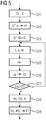
- FIG. 9 shows the solution vector Y for the case in which, in addition to the correction quantities re1, im1 for the fundamental oscillation, the correction quantities re2, im2 for the first harmonic are also determined and the highest power of the time t considered in the model 12 is the third power.
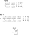
- FIG. 10 shows the matrix A for the case that determines only the correction quantities re1, im1 for the fundamental and the highest power of time t considered in model 12 is the third power.
- FIG. 11 shows the matrix A for the case in which, in addition to the correction quantities re1, im1 for the fundamental oscillation, the correction quantities re2, im2 for the first harmonic are determined and the highest power of the time t considered in the model 12 is the third power.
- tn are the detection times tn at which the respective green sheets ⁇ 'were detected.
- FIG. 12 b is as shown in FIG. 12 a Rohlagen vector.
- the highest power of time t considered in model 12 would be the second power. In this case would be in the in the FIGS. 8 and 9 represented solution vector Y the last component omitted and hereby corresponding to the in the FIGS. 10 and 11 represented matrix A the last column omitted. It would also be possible for the highest power of time t considered in model 12 to be the fourth power. In this case would be in the in the FIGS. 8 and 9 shown solution vector Y additionally as further, in the FIGS. 8 and 9 not shown component of the model parameters k4 occur and hereby corresponding in the in the FIGS. 10 and 11 A further column is added to matrix A shown, in which in each case the fourth power of the detection times tn is entered.
- the present invention has many advantages.
- the determination of the correction quantities rej, imj is possible without any additional hardware.
- a residual error remaining in the actual position ⁇ can be reduced to less than 20% of the error which is present in the respective corresponding blank sheet ⁇ '.
Landscapes
- Engineering & Computer Science (AREA)
- Physics & Mathematics (AREA)
- General Physics & Mathematics (AREA)
- Automation & Control Theory (AREA)
- Human Computer Interaction (AREA)
- Manufacturing & Machinery (AREA)
- Power Engineering (AREA)
- Control Of Ac Motors In General (AREA)
- Control Of Electric Motors In General (AREA)
Abstract
Ein elektrischer Antrieb weist eine über einen Umrichter (2) mit elektrischer Energie versorgte elektrische Maschine (1) auf. In einem Normalbetrieb nimmt eine Antriebssteuerung (5) für den elektrischen Antrieb kontinuierlich von einem eine Drehstellung einer Rotorwelle (8) der elektrischen Maschine (1) erfassenden Lagegeber (9) jeweils Rohsignale (x, y, α') entgegen und ermittelt anhand der Rohsignale (x, y, α')in Verbindung mit Korrekturgrößen (rej, imj) jeweils eine Istlage (a) der Rotorwelle (8). In Abhängigkeit von einer jeweiligen Solllage (α*) und der jeweiligen Istlage (a) oder einer jeweiligen Solldrehzahl (n*) und einer unter Verwendung der jeweiligen Istlage (a) ermittelten jeweiligen Istdrehzahl (n) der elektrischen Maschine (1) ermittelt sie jeweilige Steuersignale (U*) für den Umrichter (2) und gibt sie an den Umrichter (2) aus. In einem Sonderbetrieb ermittelt die Antriebssteuerung (5) zunächst Steuersignale (U*) für den Umrichter (2), aufgrund derer die Rotorwelle (8) mit einer Anfangsdrehzahl (n1) rotiert, und gibt sie an den Umrichter (2) aus. Sodann betreibt sie die elektrische Maschine (1) kraftlos, so dass die Rotorwelle (8) austrudelt. Während des Austrudelns nimmt die Antriebssteuerung (5) von dem Lagegeber (9) kontinuierlich jeweils Rohsignale (x, y, α')entgegen, ermittelt daraus jeweils eine Rohlage (α') der Rotorwelle (8) und speichert sie. Anhand einer Vielzahl von im Sonderbetrieb ermittelten Rohlagen (α') ermittelt sie die Korrekturgrößen (rej, imj) und hinterlegt sie in einem Korrekturgrößenspeicher (11), so dass sie im Normalbetrieb für die Ermittlung der jeweiligen Istlage (a) zur Verfügung stehen.An electrical drive has an electrical machine (1) supplied with electrical energy via a converter (2). In normal operation, a drive control (5) for the electric drive continuously receives raw signals (x, y, α ') from a position sensor (9) detecting a rotational position of a rotor shaft (8) of the electrical machine (1) and determines them on the basis of the raw signals (x, y, α ') in conjunction with correction variables (rej, imj) each an actual position (a) of the rotor shaft (8). Depending on a respective target position (α *) and the respective actual position (a) or a respective target speed (n *) and a respective actual speed (n) of the electrical machine (1) determined using the respective actual position (a), it determines the respective Control signals (U *) for the converter (2) and outputs them to the converter (2). In a special operation, the drive control (5) first determines control signals (U *) for the converter (2), based on which the rotor shaft (8) rotates at an initial speed (n1), and outputs them to the converter (2). Then it operates the electric machine (1) without power, so that the rotor shaft (8) coasts down. While coasting down, the drive controller (5) continuously receives raw signals (x, y, α ') from the position transmitter (9), determines a raw position (α') of the rotor shaft (8) and stores it. Using a large number of raw positions (α ') determined in special operation, it determines the correction variables (rej, imj) and stores them in a correction quantity memory (11) so that they are available in normal operation for determining the respective actual position (a).
Description
Die vorliegende Erfindung geht aus von einer Antriebssteuerung für einen elektrischen Antrieb, der eine über einen Umrichter mit elektrischer Energie versorgte elektrische Maschine aufweist, wobei die Antriebssteuerung in einem Normalbetrieb kontinuierlich
- von einem eine Drehstellung einer Rotorwelle der elektrischen Maschine erfassenden Lagegeber jeweils Rohsignale entgegennimmt,
- anhand der jeweiligen Rohsignale in Verbindung mit Korrekturgrößen jeweils eine Istlage der Rotorwelle ermittelt und
- in Abhängigkeit von einer jeweiligen Solllage und der jeweiligen Istlage oder einer jeweiligen Solldrehzahl und einer unter Verwendung der jeweiligen Istlage ermittelten jeweiligen Istdrehzahl der Rotorwelle jeweilige Steuersignale für den Umrichter ermittelt und an den Umrichter ausgibt.
- receiving raw signals from a position sensor detecting a rotational position of a rotor shaft of the electric machine,
- determined in each case an actual position of the rotor shaft on the basis of the respective raw signals in conjunction with correction variables and
- in response to a respective desired position and the respective actual position or a respective desired speed and determined using the respective actual position respective actual speed of the rotor shaft respective control signals for the inverter determined and outputs to the inverter.
Die vorliegende Erfindung geht weiterhin aus von einem elektrischen Antrieb, der einen Umrichter, eine über den Umrichter mit elektrischer Energie versorgte elektrische Maschine und eine Antriebssteuerung aufweist.The present invention is further based on an electric drive which has a converter, an electrical machine supplied with electrical energy via the converter and a drive controller.
Bei geregelten elektrischen Maschinen wird häufig zur Messung von Lage oder Drehzahl ein Lagegeber an die Rotorwelle angebaut. Der Lagegeber liefert sodann im Betrieb der elektrischen Maschine jeweils Rohsignale, anhand derer eine jeweilige Istlage der Rotorwelle ermittelt wird und/oder unter Differenzierung der jeweiligen Istlage eine jeweilige Istdrehzahl der Rotorwelle ermittelt wird. Die jeweilige Istlage wird sodann zur Lageregelung auf eine Solllage verwendet bzw. die jeweilige Istdrehzahl zur Drehzahlregelung auf eine Solldrehzahl verwendet.In regulated electrical machines, a position sensor is often attached to the rotor shaft for measuring position or speed. During operation of the electric machine, the position sensor then supplies raw signals, by means of which a respective actual position of the rotor shaft is determined and / or a respective actual rotational speed of the rotor shaft is determined by differentiating the respective actual position. The respective actual position is then used to position control to a desired position or the respective actual speed used for speed control to a target speed.
In der Praxis geschieht es oftmals, dass die Motorwelle und die Geberwelle einen - wenn auch nur geringen - Versatz zueinander aufweisen. Ein derartiger Versatz führt in den von dem Lagegeber ausgegebenen Rohsignalen zu einem systematischen Messfehler. Der Messfehler ist periodisch zur Drehstellung der Rotorwelle, d.h. der Istlage. In manchen Fällen weist der Fehler ausschließlich oder nahezu ausschließlich eine Komponente auf, deren Periodizität mit der Periodizität der Drehstellung korrespondiert (Grundschwingung). In anderen Fällen weist der Fehler zusätzlich weitere Komponenten auf, deren Periodizität mit einem ganzzahligen Vielfachen der Periodizität der Drehstellung korrespondiert (Oberschwingungen). Insbesondere die erste Oberschwingung, bei welcher die Periodizität des Fehlers mit dem Doppelten der Periodizität der Drehstellung korrespondiert, ist oftmals von Bedeutung. Die Fehler sind besonders unangenehm, wenn aus der ermittelten Istlage durch Differenzieren die Drehzahl ermittelt wird. Denn aufgrund der Differenzierung steigt die Amplitude des Fehlers proportional mit der Drehzahl an.In practice, it often happens that the motor shaft and the encoder shaft have a - albeit small - offset from one another. Such an offset leads to a systematic measurement error in the raw signals output by the position encoder. The measurement error is periodic to the rotational position of the rotor shaft, i. the actual situation. In some cases, the error exclusively or almost exclusively on a component whose periodicity with the periodicity of the rotational position corresponds (fundamental). In other cases, the error additionally has other components whose periodicity corresponds to an integer multiple of the periodicity of the rotational position (harmonics). In particular, the first harmonic, in which the periodicity of the error corresponds to twice the periodicity of the rotational position, is often important. The errors are particularly unpleasant if the speed is determined from the determined actual position by differentiating. Because of the differentiation, the amplitude of the error increases proportionally with the speed.
Im optimalen Fall wird der Fehler durch eine entsprechend genaue Positionierung des Gebers beim Anbau an die elektrische Maschine vermieden oder zumindest gering gehalten. In anderen Fällen wird der Fehler durch Korrekturgrößen berücksichtigt. Die vorliegende Erfindung betrifft die letztgenannte Vorgehensweise, bei welcher der Fehler durch Korrekturgrößen berücksichtigt.In the optimal case, the error is avoided by a correspondingly accurate positioning of the encoder when mounting to the electric machine or at least kept low. In other cases, the error is taken into account by correction variables. The present invention relates to the latter approach in which the error takes account of correction quantities.
Die Aufgabe der vorliegenden Erfindung besteht darin, Möglichkeiten zu schaffen, mittels derer die benötigten Korrekturgrößen auf einfache und zuverlässige Weise ermittelt werden können.The object of the present invention is to provide possibilities by means of which the required correction variables can be determined in a simple and reliable manner.
Die Aufgabe wird durch eine Antriebssteuerung mit den Merkmalen des Anspruchs 1 gelöst. Vorteilhafte Ausgestaltungen der Antriebssteuerung sind Gegenstand der abhängigen Ansprüche 2 bis 8.The object is achieved by a drive control with the features of
Erfindungsgemäß wird eine Antriebssteuerung der eingangs genannten Art dadurch ausgestaltet, dass die Antriebssteuerung in einem Sonderbetrieb
- zunächst Steuersignale für den Umrichter ermittelt, aufgrund derer die Rotorwelle mit einer Anfangsdrehzahl rotiert, und diese Steuersignale an den Umrichter ausgibt,
- sodann die elektrische Maschine kraftlos betreibt, so dass die Rotorwelle austrudelt,
- während des Austrudelns der Rotorwelle von dem Lagegeber kontinuierlich jeweils Rohsignale entgegennimmt und anhand der jeweiligen Rohsignale jeweils eine Rohlage der Rotorwelle ermittelt und zwischenspeichert,
- anhand einer Vielzahl von im Sonderbetrieb ermittelten Rohlagen die Korrekturgrößen ermittelt und
- die Korrekturgrößen in einem Korrekturgrößenspeicher der Antriebssteuerung hinterlegt, so dass sie im Normalbetrieb für die Ermittlung der jeweiligen Istlage zur Verfügung stehen.
- first determines control signals for the inverter, due to which rotates the rotor shaft with an initial speed, and outputs these control signals to the inverter,
- then the electric machine operates powerless, so that the rotor shaft blows,
- during the unwinding of the rotor shaft of the position sensor continuously receives raw signals respectively and determined on the basis of the respective raw signals in each case a raw layer of the rotor shaft, and caches,
- Based on a variety of determined in special operation Rohlagen the correction values determined and
- the correction values are stored in a correction quantity memory of the drive control, so that they are available in normal operation for the determination of the respective actual position.
Durch diese Vorgehensweise können die Korrekturgrößen von der Antriebssteuerung selbst ermittelt werden, ohne weitere Komponenten zu benötigen. Insbesondere ist es nicht erforderlich, die Korrekturgrößen anderweitig - beispielsweise mittels eines weiteren Lagegebers, der seinerseits fehlerbehaftet sein kann oder aber hochgenau positioniert werden muss - zu ermitteln.By doing so, the correction quantities can be determined by the drive controller itself without the need for additional components. In particular, it is not necessary to determine the correction quantities in another way, for example by means of a further position sensor, which in turn may be faulty or else must be positioned with high precision.
Vorzugsweise wird der Sonderbetrieb nur so lange beibehalten, solange die Rotorwelle schnell genug rotiert. Vorzugsweise prüft die Antriebssteuerung im Sonderbetrieb daher anhand der jeweiligen Rohsignale jeweils, ob eine aktuelle Drehzahl der Rotorwelle eine Minimaldrehzahl erreicht oder unterschreitet. Bei Erreichen oder Unterschreiten der Minimaldrehzahl beendet die Antriebssteuerung das Ermitteln und Zwischenspeichern der Rohlagen und geht zur Ermittlung der Korrekturgrößen über. Dieser Ansatz beruht auf dem Gedanken, dass bei einer hinreichend hoher Drehzahl (d.h. einer Drehzahl oberhalb der Minimaldrehzahl) Störungen der gleichmäßigen Rotation beispielsweise durch Nutrastmomente und dergleichen hinreichend klein sind, so dass sie vernachlässigt werden können. Bei einer kleineren Drehzahl (d.h. einer Drehzahl unterhalb der Minimaldrehzahl) können derartige Störungen hingegen Fehler bewirken, die nicht mehr ohne weiteres vernachlässigt werden können.Preferably, the special operation is maintained only as long as long as the rotor shaft rotates fast enough. In the special operation, the drive control therefore preferably checks in each case on the basis of the respective raw signals whether a current rotational speed of the rotor shaft reaches or falls below a minimum rotational speed. Upon reaching or falling below the minimum speed, the drive control terminates the determination and buffering of the green sheets and goes to determine the correction variables. This approach is based on the idea that at a sufficiently high speed (ie a speed above the minimum speed) disturbances of the uniform rotation, for example by Nutrastmomente and the like are sufficiently small so that they can be neglected. At a lower speed (ie a speed below the minimum speed), however, such disturbances can cause errors that can not be easily ignored.
In der Regel modelliert die Antriebssteuerung das Austrudeln der Rotorwelle gemäß einem Modell, das eine Anzahl von Modellparametern aufweist. Vorzugsweise ermittelt die Antriebssteuerung anhand der im Sonderbetrieb ermittelten Rohlagen nicht nur die Korrekturgrößen, sondern auch die Modellparameter. Dadurch können insbesondere durch das Modell als solches hervorgerufene Fehler verringert bzw. vermieden werden.In general, the drive controller models the coasting of the rotor shaft according to a model having a number of model parameters. Preferably, the drive control not only determines the correction quantities but also the model parameters on the basis of the raw sheets determined in the special operation. This can be reduced or avoided in particular by the model as such caused errors.
Das Modell kann beispielsweise die Form ![]()
![]()
Die höchste in dem Modell betrachtete Potenz der Zeit ist mindestens die zweite Potenz der Zeit, d.h. die Beschleunigung. Anderenfalls würde angenommen, dass die einmal eingestellte Drehzahl - d.h. die Anfangsdrehzahl - konstant bleibt. Oftmals ist es ausreichend, wenn die höchste in dem Modell betrachtete Potenz der Zeit die dritte Potenz der Zeit ist, d.h. der Ruck. In manchen Fällen kann es jedoch erforderlich sein, zusätzlich auch noch die vierte Potenz der Zeit zu betrachten. Eine Berücksichtigung noch höherer Potenzen der Zeit ist zwar möglich, in der Regel aber nicht erforderlich.The highest power of time considered in the model is at least the second power of time, ie the acceleration. Otherwise it would be assumed that the speed set once - ie the initial speed - remains constant. Often it is sufficient if the highest power of time considered in the model is the third power of time, ie the jerk. In some cases, however, it may be necessary be, in addition to consider the fourth power of time. A consideration of even higher powers of time is possible, but usually not required.
Zur Fehlerkorrektur ermittelt die Antriebssteuerung im Normalbetrieb aus den jeweils entgegengenommenen Rohsignalen jeweils eine Rohlage und sodann aus der jeweiligen Rohlage anhand der Beziehung 
Vorzugsweise ermittelt die Antriebssteuerung die Korrekturgrößen anhand eines überbestimmten Gleichungssystems, wobei die Antriebssteuerung weiterhin die Korrekturgrößen gemäß einem Verfahren ermittelt, bei dem die Fehlerquadrate minimiert werden. Dadurch kann die Genauigkeit der Ermittlung der Korrekturgrößen gesteigert werden.The drive controller preferably determines the correction variables on the basis of an overdetermined equation system, wherein the drive control furthermore determines the correction variables in accordance with a method in which the error squares are minimized. Thereby, the accuracy of the determination of the correction quantities can be increased.
Die Aufgabe wird weiterhin durch einen elektrischen Antrieb mit den Merkmalen des Anspruchs 9 gelöst. Erfindungsgemäß ist bei einem elektrischen Antrieb der eingangs genannten Art die Antriebssteuerung als erfindungsgemäße Antriebssteuerung ausgebildet.The object is further achieved by an electric drive with the features of claim 9. According to the invention, the drive control is designed as an inventive drive control in an electric drive of the type mentioned.
Die oben beschriebenen Eigenschaften, Merkmale und Vorteile dieser Erfindung sowie die Art und Weise, wie diese erreicht werden, werden klarer und deutlicher verständlich im Zusammenhang mit der folgenden Beschreibung der Ausführungsbeispiele, die in Verbindung mit den Zeichnungen näher erläutert werden. Hierbei zeigen in schematischer Darstellung:
- FIG 1
- einen elektrischen Antrieb und seine Steuerung,
- FIG 2
- eine Antriebssteuerung,
- FIG 3
bis 5 - je ein Ablaufdiagramm,
- FIG 6
- ein Zeitdiagramm,
- FIG 7
- einen Lösungsansatz zur Bestimmung von Korrekturgrößen und Modellparametern,
- FIG 8 und 9
- je einen Lösungsvektor,
- FIG 10
und 11 - je eine Matrix und
- FIG 12
- einen Rohlagenvektor.
- FIG. 1
- an electric drive and its control,
- FIG. 2
- a drive control,
- 3 to 5
- one flowchart each,
- FIG. 6
- a time diagram,
- FIG. 7
- a solution for the determination of correction quantities and model parameters,
- FIGS. 8 and 9
- one solution vector each,
- FIGS. 10 and 11
- one matrix each and
- FIG. 12
- a Rohlagen vector.
Gemäß
Die Antriebssteuerung 5 ist in
Die Kommunikation zwischen der Antriebssteuerung 5 und der weiteren Steuereinrichtung 7 - also die Übermittlung der übergeordneten Sollwerte und die Übermittlung der Istwerte - erfolgt mit einem weiteren Arbeitstakt, der je nach Art des übergeordneten Sollwertes ein Drehzahlreglertakt oder ein Lagereglertakt oder ein Momentreglertakt ist. Der weitere Arbeitstakt liegt in der Regel bei mindestens 8 kHz, manchmal auch bei größeren Werten wie beispielsweise 16 kHz oder 32 kHz. In jedem Fall aber ist der weitere Arbeitstakt maximal so groß wie der Stromreglertakt. Wenn also beispielsweise der Stromreglertakt 16 kHz beträgt, kann der weitere Arbeitstakt beispielsweise 8 kHz oder 16 kHz sein, nicht aber 32 kHz.The communication between the
Der Lageistwert α - nachfolgend auch als Istlage α bezeichnet - entspricht der momentanen Drehstellung einer Rotorwelle 8 der elektrischen Maschine 1. Die Istlage α oder eine unter Verwendung der Istlage α ermittelte Istdrehzahl n (d.h. der Drehzahlistwert) wird von der Antriebssteuerung 5 intern verwendet, um die Steuersignale U* korrekt zu ermitteln. Zur Erfassung der Drehstellung = Istlage α ist ein Lagegeber 9 vorhanden. Der Lagegeber 9 erfasst Gebersignale, beispielsweise ein sogenanntes Sinussignal y und ein sogenanntes Cosinussignal x. Es ist möglich, dass der Lagegeber 9 aus dem Sinussignal y und dem Cosinussignal x selbst einen Winkel α' (= Rohlage α') ermittelt und als Rohsignal α' den Winkel α' an die Antriebssteuerung 5 übermittelt. Alternativ ist es möglich, dass der Lagegeber 9 als Rohsignale x, y das Sinussignal y und das Cosinussignal x an die Antriebssteuerung 5 übermittelt und die Antriebssteuerung 5 daraus die Rohlage α' ermittelt. Welche dieser beiden Vorgehensweisen ergriffen wird, ist im Rahmen der vorliegenden Erfindung von untergeordneter Bedeutung. Auch ist es alternativ möglich, die vom Lagegeber 9 an die Antriebssteuerung 5 übermittelten Signale direkt an die Antriebssteuerung 5 zu übermitteln oder über den Umrichter 2 an die Antriebssteuerung 5 zu übermitteln. Auch hier ist im Rahmen der vorliegenden Erfindung von untergeordneter Bedeutung, welche dieser beiden Vorgehensweisen ergriffen wird. Entscheidend ist, dass die Übermittlung im Stromreglertakt erfolgt.The actual position α - hereinafter also referred to as actual position α - corresponds to the instantaneous rotational position of a
Gemäß
- In einem Schritt S1
nimmt die Antriebssteuerung 5 ein Modussignal B entgegen. Das Modussignal B kann mindestens zwei verschiedene Werte aufweisen,nachfolgend als 0 und 1 bezeichnet. Es kann gegebenenfalls auch andere Werte aufweisen.Die Antriebssteuerung 5 prüft in einem Schritt S2, ob das ModussignalB den Wert 0 aufweist. In diesem Fall geht dieAntriebssteuerung 5 zu einem Schritt S3 über. Im Schritt S3 führt dieAntriebssteuerung 5 einen Normalbetrieb aus. Der Normalbetrieb wird später in Verbindung mitFIG 4 näher erläutert werden. Anderenfallsprüft die Antriebssteuerung 5 in einem Schritt S4, ob das ModussignalB den Wert 1 aufweist. In diesem Fall geht dieAntriebssteuerung 5 zu einem Schritt S5 über. Im Schritt S5 führt dieAntriebssteuerung 5 einen Sonderbetrieb aus. Anderenfalls geht dieAntriebssteuerung 5 zu einem Schritt S6 über. Im Schritt S6 führt dieAntriebssteuerung 5 andere Maßnahmen aus, die im Rahmen der vorliegenden Erfindung von untergeordneter Bedeutung sind. Die Abfolge der Schritte S1, S2, S3 erfolgt im Stromreglertakt. Der Schritt S5 und gegebenenfalls auch der Schritt S6 können längere Zeit in Anspruch nehmen.
- In a step S1, the
drive controller 5 receives a mode signal B against. The mode signal B may have at least two different values, hereinafter referred to as 0 and 1. It may also have other values if necessary. Thedrive controller 5 checks in a step S2 whether the mode signal B has thevalue 0. In this case, thedrive controller 5 proceeds to a step S3. In step S3, thedrive controller 5 performs a normal operation. Normal operation will be used later in conjunction withFIG. 4 be explained in more detail. Otherwise, thedrive controller 5 checks in a step S4 whether the mode signal B has thevalue 1. In this case, thedrive controller 5 proceeds to a step S5. In step S5, thedrive controller 5 executes a special operation. Otherwise, thedrive controller 5 proceeds to a step S6. In step S6, thedrive controller 5 carries out other measures that are of minor importance in the context of the present invention. The sequence of steps S1, S2, S3 takes place in the current controller cycle. The step S5 and optionally also the step S6 may take a longer time.
Es ist auch möglich, dass das Modussignal B ausschließlich die Werte 0 und 1 annehmen kann. In diesem Fall können die Schritte S4 und S6 entfallen und kann vom Schritt S2 gegebenenfalls direkt zum Schritt S5 übergegangen werden.It is also possible that the mode signal B can only assume the
Nachfolgend wird in Verbindung mit
Im Normalbetrieb wird der Antriebssteuerung 5 in einem Schritt S11 ein übergeordneter Sollwert bekannt. Beispielsweise kann die Antriebssteuerung 5 im Schritt S11 von der weiteren Steuereinrichtung 7 einen Drehzahlsollwert n* entgegennehmen oder den zuletzt entgegengenommenen Drehzahlsollwert n* erneut verwenden. In einem Schritt S12 nimmt die Antriebssteuerung 5 vom Lagegeber 9 dessen Rohsignale x, y, α' entgegen.In normal operation, the
In einem Schritt S13 ermittelt die Antriebssteuerung 5 aus den Rohsignalen x, y, α' eine Istlage α der Rotorwelle 8. Insbesondere ermittelt die Antriebssteuerung 5 die Istlage α aus der zugehörigen Rohlage α' in Verbindung mit Korrekturgrößen rej, imj (mit j = 1, 2, 3, ...). Falls die Antriebssteuerung 5 im Schritt S12 als Rohsignale das Sinussignal y und das Cosinussignal x entgegengenommen hat, ermittelt die Antriebssteuerung 5 im Schritt S13 zuvor aus den Rohsignalen x, y die Rohlage α'. Anderenfalls ist das Rohsignal α' selbst bereits die Rohlage α', die Ermittlung der Rohlage α' also trivial.In a step S13, the
Der Schritt S13 kann auf verschiedene Art und Weise ausgestaltet sein. Insbesondere ist es möglich, dass die Antriebssteuerung 5 im Schritt S13 die Istlage α gemäß der Beziehung 
Im einfachsten Fall kann der Index j nur den Wert 1 annehmen. Alternativ kann der Index j den Wert 2 annehmen. Höhere Werte als 2 sind zwar ebenfalls möglich, im Regelfall aber nicht erforderlich.In the simplest case, the index j can only assume the
Soweit erforderlich, ermittelt die Antriebssteuerung 5 in einem Schritt S14 die Istdrehzahl n. Sofern die Ermittlung erfolgt, erfolgt sie unter Verwertung der Istlage α, insbesondere durch zeitliche Differenzierung der Istlage α. In einem Schritt S15 ermittelt die Antriebssteuerung 5, beispielsweise anhand des Drehzahlsollwertes n* und der Istdrehzahl n oder des Lagesollwertes α* und der zugehörigen Istlage α, die zugehörigen Steuersignale U* für den Umrichter 2 und gibt sie an den Umrichter 2 aus. Soweit erforderlich, übermittelt die Antriebssteuerung 5 weiterhin in einem Schritt S16 die Istlage α oder eine andere Größe, beispielsweise die Istdrehzahl n, an die weitere Steuereinrichtung 7.If necessary, the
Nachfolgend wird in Verbindung mit
Im Sonderbetrieb löscht die Antriebssteuerung 5 zunächst in einem Schritt S21 den Inhalt eines Pufferspeichers 10. Als nächstes ermittelt die Antriebssteuerung 5 in einem Schritt S22 Steuersignale U* für den Umrichter 2, welche bewirken, dass die Rotorwelle 8 mit einer Anfangsdrehzahl n1 rotiert. Die Ermittlung derartiger Steuersignale U* ist Fachleuten ohne weiteres bekannt. Im Schritt S22 erfolgt auch die Ausgabe dieser Steuersignale U* an den Umrichter 2. Die Anfangsdrehzahl n1 wird relativ hoch gewählt, beispielsweise bei mehreren 1000 U/min.
Sodann ermittelt die Antriebssteuerung 5 in einem Schritt S23 andere Steuersignale U* für den Umrichter 2. Diese Steuersignale U* bewirken, dass die Antriebssteuerung 5 die elektrische Maschine 1 kraftlos betreibt. Auch die Ermittlung derartiger Steuersignale U* ist Fachleuten ohne weiteres bekannt. Beispielsweise kann die Ausgabe an Schaltimpulsen an die internen Halbleiterschalter 6 des Umrichters 2 gesperrt werden oder kann der Stromsollwert für die Phasen 4 auf 0 gesetzt werden. Auch diese Steuersignale U* werden im Schritt S23 an den Umrichter 2 ausgegeben. Die Ausführung des Schrittes S23 wird im weiteren Verlauf, d.h. insbesondere im Verlauf der wiederholten Ausführung der Schritte S24 bis S27, beibehalten. Auch ist es möglich, dies dadurch zu erreichen, dass der Schritt S23 zu einem Bestandteil der die Schritte S24 bis S27 enthaltenden Schleife gemacht wird.Then, the
Aufgrund des kraftlosen Betriebs der elektrischen Maschine 1 trudelt die Rotorwelle 8 aus. Die Drehzahl n der Rotorwelle 8 verringert sich also entsprechend der Darstellung in
In diesem Zustand - also während des Austrudelns der Rotorwelle 8 - werden wiederholt (und zwar im Stromreglertakt) die Schritte S24 bis S27 ausgeführt. Im Schritt S24 nimmt die Antriebssteuerung 5 von dem Lagegeber 9 jeweils Rohsignale x, y, α' entgegen. Im Schritt S25 ermittelt die Antriebssteuerung 5 anhand der jeweiligen Rohsignale x, y, α' jeweils die zugehörige Rohlage α'. Falls die Antriebssteuerung 5 im Schritt S25 als Rohsignal α' bereits die Rohlage α' entgegengenommen hat, die Ermittlung der Rohlage α' trivial. In diesem Fall ist der Schritt S25 entartet.In this state-that is, during the unwinding of the rotor shaft 8-the steps S24 to S27 are repeatedly executed (namely in the current controller cycle). In step S24, the
Im Schritt S26 speichert die Antriebssteuerung 5 die Rohlage α' in den Pufferspeicher 10 ein. Das Speichern im Pufferspeicher 10 erfolgt derart, dass die jeweilige Rohlage α' zusätzlich zu bereits im Pufferspeicher 10 hinterlegten Rohlagen α' gespeichert wird. Soweit erforderlich, wird der jeweiligen Rohlage α' weiterhin der zugehörige Erfassungszeitpunkt tn (n = 1, 2, 3, ... N) zugeordnet und ebenfalls im Pufferspeicher 10 hinterlegt.In step S26, the
Im Schritt S27 prüft die Antriebssteuerung 5, ob das Ermitteln und Zwischenspeichern der Rohlagen α' beendet werden soll. Beispielsweise kann die Antriebssteuerung 5 im Schritt S27 anhand der jeweiligen Rohlage α' jeweils eine aktuelle Drehzahl n der Rotorwelle 8 ermitteln und prüfen, ob die aktuelle Drehzahl n eine Minimaldrehzahl n2 erreicht oder unterschreitet. Die Minimaldrehzahl n2 kann bei einem geeigneten Prozentsatz der Anfangsdrehzahl n1 liegen, beispielsweise irgendwo zwischen 60 % und 20 % der Anfangsdrehzahl n1, insbesondere zwischen 50 % und 30 %. Gemäß
Wenn das Ermitteln und Zwischenspeichern der Rohlagen α' beendet wird, geht die Antriebssteuerung 5 zu einem Schritt S28 über. Im Schritt S28 ermittelt die Antriebssteuerung 5 zumindest die Korrekturgrößen rej, imj. Die Ermittlung der Korrekturgrößen rej, imj erfolgt anhand der im Pufferspeicher 10 hinterlegten Rohlagen α'. Hierbei wird nicht nur eine einzelne Rohlage α' verwertet, sondern eine Vielzahl von im Pufferspeicher 10 hinterlegten Rohlagen α'. Die ermittelten Korrekturgrößen rej, imj hinterlegt die Antriebssteuerung 5 in einem Schritt S29 in einem Korrekturgrößenspeicher 11. Dadurch stehen die Korrekturgrößen rej, imj im nachfolgenden Normalbetrieb für die Ermittlung der jeweiligen Istlage α zur Verfügung.When the detection and buffering of the green sheets α 'is ended, the
Die Antriebssteuerung 5 modelliert das Austrudeln der Rotorwelle 8 gemäß einem Modell 12. Das Modell 12 weist eine Anzahl von Modellparametern ki (mit i = 1, 2, 3 ...) auf. Beispielsweise kann das Modell 12 entsprechend der Darstellung in ![]()
![]()
Vorzugsweise ermittelt die Antriebssteuerung 5 entsprechend der Darstellung in
Im Rahmen des Schrittes S27 ermittelt die Antriebssteuerung 5 die Korrekturgrößen rej, imj und gegebenenfalls auch die Modellparameter ki anhand eines überbestimmten Gleichungssystems. Die Ermittlung erfolgt weiterhin vorzugsweise gemäß einem Verfahren, bei dem die Fehlerquadrate minimiert werden. Insbesondere kann die Antriebssteuerung 5 die Korrekturgrößen rej, imj und die Modellparameter ki entsprechend der Darstellung in ![]()
![]()
Y ist ein Lösungsvektor Y, dessen Komponenten die gesuchten Korrekturgrößen rej, imj und die gesuchten Modellparameter ki sind.
A ist eine Matrix. AT ist die zugehörige transponierte Matrix.
b ist entsprechend der Darstellung in
Es wäre möglich, dass die höchste in dem Modell 12 betrachtete Potenz der Zeit t die zweite Potenz ist. In diesem Fall würde in dem in den
Zusammengefasst betrifft die vorliegende Erfindung somit folgenden Sachverhalt:
- Ein elektrischer Antrieb weist eine über einen Umrichter 2 mit elektrischer Energie versorgte elektrische Maschine 1 auf. In einem Normalbetrieb nimmt eine Antriebssteuerung 5 für den elektrischen Antrieb kontinuierlich von einem eine Drehstellung einer Rotorwelle 8 der elektrischen Maschine 1 erfassenden Lagegeber 9 jeweils Rohsignale x, y, α' entgegen und ermittelt anhand der Rohsignale x, y, α' in Verbindung mit Korrekturgrößen rej, imj jeweils eine Istlage α der
Rotorwelle 8. In Abhängigkeit von einer jeweiligen Solllage α* und der jeweiligen Istlage α oder einer jeweiligen Solldrehzahl n* und einer unter Verwendung der jeweiligen Istlage α ermittelten jeweiligen Istdrehzahl n der elektrischen Maschine 1 ermittelt sie jeweilige Steuersignale U* fürden Umrichter 2 und gibt sie anden Umrichter 2 aus. In einem Sonderbetriebermittelt die Antriebssteuerung 5 zunächst Steuersignale U* fürden Umrichter 2, aufgrund derer dieRotorwelle 8 mit einer Anfangsdrehzahl n1 rotiert, und gibt sie anden Umrichter 2 aus. Sodann betreibt sie dieelektrische Maschine 1 kraftlos, so dass dieRotorwelle 8 austrudelt. Während des Austrudelnsnimmt die Antriebssteuerung 5 von dem Lagegeber 9 kontinuierlich jeweils Rohsignale x, y, α' entgegen, ermittelt daraus jeweils eine Rohlage α'der Rotorwelle 8 und speichert sie. Anhand einer Vielzahl von im Sonderbetrieb ermittelten Rohlagen α' ermittelt sie die Korrekturgrößen rej, imj und hinterlegt sie ineinem Korrekturgrößenspeicher 11, so dass sie im Normalbetrieb für die Ermittlung der jeweiligen Istlage α zur Verfügung stehen.
- An electric drive has an
electrical machine 1 supplied with electrical energy via aconverter 2. In a normal operation, adrive control 5 for the electric drive continuously picks up raw signals x, y, α 'from a position sensor 9 detecting a rotational position of arotor shaft 8 of theelectric machine 1 and uses the raw signals x, y, α' in conjunction with correction values rej, imj each an actual position α of therotor shaft 8. Depending on a respective desired position α * and the respective actual position α or a respective setpoint speed n * and a determined using the respective actual position α respective actual speed n of theelectric machine 1, it determines respective control signals U * for theinverter 2 and outputs them to theinverter 2 off. In a special operation, thedrive controller 5 first determines control signals U * for theconverter 2, on the basis of which therotor shaft 8 rotates at an initial rotational speed n1, and outputs it to theconverter 2. Then it operates theelectric machine 1 powerless, so that therotor shaft 8 discharges. During the unwinding, thedrive control 5 continuously receives raw signals x, y, α 'from the position sensor 9, determines from these in each case a blank layer α' of therotor shaft 8 and stores them. Based on a variety of determined in special operation Rohlagen α 'it determines the correction quantities rej, imj and deposited them in acorrection amount memory 11 so that they are available in normal operation for the determination of the respective actual position α.
Die vorliegende Erfindung weist viele Vorteile auf. Insbesondere ist die Ermittlung der Korrekturgrößen rej, imj ohne jegliche zusätzliche Hardware möglich. Es werden nur die sowieso vorhandene Antriebssteuerung 5 und der sowieso vorhandene Lagegeber 9 benötigt. Dennoch ist eine recht genaue Ermittlung der Korrekturgrößen rej, imj möglich. Ein in der Istlage α verbleibender Restfehler kann auf unter 20 % des Fehlers reduziert werden, der in der jeweils korrespondierenden Rohlage α' vorhanden ist.The present invention has many advantages. In particular, the determination of the correction quantities rej, imj is possible without any additional hardware. There are only the existing existing
Obwohl die Erfindung im Detail durch das bevorzugte Ausführungsbeispiel näher illustriert und beschrieben wurde, so ist die Erfindung nicht durch die offenbarten Beispiele eingeschränkt und andere Variationen können vom Fachmann hieraus abgeleitet werden, ohne den Schutzumfang der Erfindung zu verlassen.Although the invention has been further illustrated and described in detail by the preferred embodiment, the invention is not limited by the disclosed examples, and other variations can be derived therefrom by those skilled in the art without departing from the scope of the invention.
Claims (9)
dadurch gekennzeichnet,
dass die Antriebssteuerung in einem Sonderbetrieb
characterized,
that the drive control in a special operation
dadurch gekennzeichnet,
dass die Antriebssteuerung im Sonderbetrieb anhand der jeweiligen Rohsignale (α') jeweils prüft, ob eine aktuelle Drehzahl (n) der Rotorwelle (8) eine Minimaldrehzahl (n2) erreicht oder unterschreitet, und bei Erreichen oder Unterschreiten der Minimaldrehzahl (n2) das Ermitteln und Zwischenspeichern der Rohlagen (α') beendet und zur Ermittlung der Korrekturgrößen (rej, imj) übergeht.Drive control according to claim 1,
characterized,
that the drive control in special operation on the basis of the respective raw signals (α ') each checks whether a current speed (n) of the rotor shaft (8) reaches or falls below a minimum speed (n2), and at reaching or falling below the minimum speed (n2) determining and Caching the Rohlagen (α ') ends and goes to determine the correction quantities (rej, imj).
dadurch gekennzeichnet,
dass die Antriebssteuerung das Austrudeln der Rotorwelle (8) gemäß einem Modell (12) modelliert, dass das Modell (12) eine Anzahl von Modellparametern (ki) aufweist und dass die Antriebssteuerung anhand der im Sonderbetrieb ermittelten Rohlagen (α') auch die Modellparameter (ki) ermittelt.Drive control according to claim 1 or 2,
characterized,
in that the drive controller models the coasting of the rotor shaft (8) in accordance with a model (12), that the model (12) has a number of model parameters (ki), and that the drive control also uses the model parameters (α ') on the basis of the raw sheets (α') determined in the special mode. ki).
dadurch gekennzeichnet,
dass das Modell (12) die Form
characterized,
that the model (12) the shape
dadurch gekennzeichnet,
dass die höchste in dem Modell (12) betrachtete Potenz der Zeit (t) die zweite, dritte oder vierte Potenz ist.Drive control according to claim 4,
characterized,
that the highest power of time (t) considered in the model (12) is the second, third or fourth power.
dadurch gekennzeichnet,
dass die Antriebssteuerung im Normalbetrieb aus den jeweils entgegengenommenen Rohsignalen (x, y, α') jeweils eine Rohlage (α') ermittelt und aus der jeweiligen Rohlage (α') anhand der Beziehung

characterized,
that the drive control in normal operation from each received raw signals (x, y, α ') each have a raw layer (α ') and determined from the respective raw layer (α') based on the relationship
dadurch gekennzeichnet,
dass das höchste im Normalbetrieb berücksichtigte Vielfache der jeweiligen Rohlage (α') das Einfache oder das Zweifache der jeweiligen Rohlage (α') ist.Drive control according to claim 6,
characterized,
that the highest multiple of the respective blank ply (α ') considered in normal operation is the single or the double of the respective blank ply (α').
dadurch gekennzeichnet,
dass die Antriebssteuerung die Korrekturgrößen (rej, imj) anhand eines überbestimmten Gleichungssystems ermittelt und dass die Antriebssteuerung die Korrekturgrößen (rej, imj) gemäß einem Verfahren ermittelt, bei dem die Fehlerquadrate minimiert werden.Drive control according to one of the above claims,
characterized,
in that the drive controller determines the correction quantities (rej, imj) on the basis of an overdetermined equation system and that the drive controller determines the correction quantities (rej, imj) according to a method in which the error squares are minimized.
dadurch gekennzeichnet,
dass die Antriebssteuerung (5) als Antriebssteuerung nach einem der obigen Ansprüche ausgebildet ist.Electric drive having an inverter (2), an electrical machine (1) supplied with electrical energy via the converter (2) and a drive controller (5),
characterized,
in that the drive control (5) is designed as drive control according to one of the above claims.
Priority Applications (5)
| Application Number | Priority Date | Filing Date | Title |
|---|---|---|---|
| EP17209247.0A EP3502811A1 (en) | 2017-12-21 | 2017-12-21 | Drive controller equipped with independent error correction of position errors |
| CN201880082073.6A CN111527457B (en) | 2017-12-21 | 2018-11-19 | Drive controller with independent error correction for position error |
| US16/955,610 US11726446B2 (en) | 2017-12-21 | 2018-11-19 | Drive controller with self-contained correction function of position errors |
| PCT/EP2018/081739 WO2019120811A1 (en) | 2017-12-21 | 2018-11-19 | Drive controller with self-contained error correction function of position errors |
| EP18810944.1A EP3669241B1 (en) | 2017-12-21 | 2018-11-19 | Drive controller equipped with independent error correction of position errors |
Applications Claiming Priority (1)
| Application Number | Priority Date | Filing Date | Title |
|---|---|---|---|
| EP17209247.0A EP3502811A1 (en) | 2017-12-21 | 2017-12-21 | Drive controller equipped with independent error correction of position errors |
Publications (1)
| Publication Number | Publication Date |
|---|---|
| EP3502811A1 true EP3502811A1 (en) | 2019-06-26 |
Family
ID=60971891
Family Applications (2)
| Application Number | Title | Priority Date | Filing Date |
|---|---|---|---|
| EP17209247.0A Withdrawn EP3502811A1 (en) | 2017-12-21 | 2017-12-21 | Drive controller equipped with independent error correction of position errors |
| EP18810944.1A Active EP3669241B1 (en) | 2017-12-21 | 2018-11-19 | Drive controller equipped with independent error correction of position errors |
Family Applications After (1)
| Application Number | Title | Priority Date | Filing Date |
|---|---|---|---|
| EP18810944.1A Active EP3669241B1 (en) | 2017-12-21 | 2018-11-19 | Drive controller equipped with independent error correction of position errors |
Country Status (4)
| Country | Link |
|---|---|
| US (1) | US11726446B2 (en) |
| EP (2) | EP3502811A1 (en) |
| CN (1) | CN111527457B (en) |
| WO (1) | WO2019120811A1 (en) |
Citations (1)
| Publication number | Priority date | Publication date | Assignee | Title |
|---|---|---|---|---|
| DE102004050999A1 (en) * | 2003-10-30 | 2005-06-02 | Luk Lamellen Und Kupplungsbau Beteiligungs Kg | Electronically commutated motor operating process, involves determining correction value and storing position measurement error contained in position measuring signals in electrically commutated motor |
Family Cites Families (17)
| Publication number | Priority date | Publication date | Assignee | Title |
|---|---|---|---|---|
| JPH04275091A (en) * | 1991-02-28 | 1992-09-30 | Toshiba Corp | Drive controller for commutatorless motor |
| US7417386B2 (en) * | 2001-05-22 | 2008-08-26 | Rockwell Automation Technologies, Inc. | Electronic line shaft |
| US6903523B2 (en) * | 2003-06-04 | 2005-06-07 | William A. Peterson | Methods and apparatus for dynamically reconfiguring a pulse width modulation approach |
| US7423396B2 (en) * | 2004-06-11 | 2008-09-09 | International Rectifier Corporation | Hall sensor alignment for BLDC motor |
| DE102005004418B4 (en) * | 2005-01-31 | 2006-11-23 | Samson Aktiengesellschaft | Positioner for a fluid operated actuator |
| JP5044551B2 (en) * | 2005-06-28 | 2012-10-10 | ストライカー・コーポレイション | Electric surgical instrument with a control module including a sensor for remotely monitoring the instrument power generation unit |
| JP5369410B2 (en) * | 2007-09-05 | 2013-12-18 | セイコーエプソン株式会社 | Electric motor drive circuit and device equipped with the same |
| WO2010033460A2 (en) * | 2008-09-16 | 2010-03-25 | Kelsey-Hayes Company | Method and apparatus for controlling the position of an electric motor |
| JP2010223355A (en) * | 2009-03-24 | 2010-10-07 | Aisin Aw Co Ltd | Shift-by-wire device |
| JP5737500B2 (en) * | 2011-01-31 | 2015-06-17 | 日立オートモティブシステムズ株式会社 | Electric brake device |
| DE102011105854B4 (en) * | 2011-06-03 | 2013-04-11 | Nordex Energy Gmbh | Method for operating a wind energy plant in the event of a grid fault and such a wind turbine |
| KR101220388B1 (en) * | 2011-08-11 | 2013-01-09 | 현대자동차주식회사 | Economy running system for electric vehicle and control method thereof |
| EP2785579A2 (en) * | 2011-12-02 | 2014-10-08 | Helical Robotics, LLC | Mobile robot |
| DE102015208710A1 (en) * | 2015-05-11 | 2016-11-17 | Baumüller Nürnberg GmbH | Method for operating an electric machine and drive |
| EP3339088B1 (en) * | 2015-08-21 | 2020-01-08 | Murata Machinery, Ltd. | Mobile body |
| US10482787B2 (en) * | 2017-03-21 | 2019-11-19 | Toyota Motor Engineering & Manufacturing North America, Inc. | Selective presentation of coasting coach indicator for consecutive learned deceleration areas in close proximity |
| ES2921062T3 (en) * | 2018-05-02 | 2022-08-17 | Siemens Mobility GmbH | Rail vehicle with a drive system |
-
2017
- 2017-12-21 EP EP17209247.0A patent/EP3502811A1/en not_active Withdrawn
-
2018
- 2018-11-19 EP EP18810944.1A patent/EP3669241B1/en active Active
- 2018-11-19 US US16/955,610 patent/US11726446B2/en active Active
- 2018-11-19 CN CN201880082073.6A patent/CN111527457B/en active Active
- 2018-11-19 WO PCT/EP2018/081739 patent/WO2019120811A1/en active Search and Examination
Patent Citations (1)
| Publication number | Priority date | Publication date | Assignee | Title |
|---|---|---|---|---|
| DE102004050999A1 (en) * | 2003-10-30 | 2005-06-02 | Luk Lamellen Und Kupplungsbau Beteiligungs Kg | Electronically commutated motor operating process, involves determining correction value and storing position measurement error contained in position measuring signals in electrically commutated motor |
Also Published As
| Publication number | Publication date |
|---|---|
| CN111527457B (en) | 2023-02-28 |
| EP3669241B1 (en) | 2022-01-12 |
| US20210072722A1 (en) | 2021-03-11 |
| US11726446B2 (en) | 2023-08-15 |
| WO2019120811A1 (en) | 2019-06-27 |
| EP3669241A1 (en) | 2020-06-24 |
| CN111527457A (en) | 2020-08-11 |
Similar Documents
| Publication | Publication Date | Title |
|---|---|---|
| DE19920975B4 (en) | Electric power steering system | |
| DE102011009935B4 (en) | Method for driving an optimal operating point in a synchronous machine and a converter-fed synchronous machine | |
| EP2019482A1 (en) | System for determining the position and speed for a permanent magnet rotor of an electric machine | |
| DE112005001683T5 (en) | Motor controller | |
| DE102016008984A1 (en) | A motor control apparatus, wherein a current regeneration is adjusted, control unit for an inverter, machine learning apparatus and method thereof | |
| DE102013005941A1 (en) | Control device for a synchronous motor for controlling a synchronous motor when performing an energy recovery operation and for stopping the synchronous motor in case of failure of the power supply | |
| EP2447104A1 (en) | Method for controlling an electric revolving field machine of a mobile work machine | |
| EP0690556B1 (en) | Stop recognizing of inverter controlled motor without speed sensor by restarting | |
| EP3292301B1 (en) | Method for operating a wind turbine | |
| DE112013002987T5 (en) | Variable torque angle for electric motor | |
| DE102009038155A1 (en) | Servomotor controller for controlling servomotors in e.g. drill bit, has adjusting unit adjusting reverse correction amount based on selection of acceleration, and acceleration control instruction calculated by calculation unit | |
| EP3255513A1 (en) | Method for real-time monitoring of the power envelope and/or energy flow of a drive device and drive device and computer programme for the same | |
| DE102011089547A1 (en) | Method and device for correcting a measured value of a rotation angle of a rotor of an electrical machine | |
| DE19607688B4 (en) | Method and device for detecting and diagnosing an abnormal operating condition in a servo control system | |
| DE102013204600A1 (en) | Wind turbine with frequency measurement | |
| EP0469177B1 (en) | Method and device for restarting an induction motor | |
| DE102011006300A1 (en) | Method and monitoring unit for checking position values | |
| DE102017211481A1 (en) | Device for controlling a draft-reducing mill | |
| EP3669241B1 (en) | Drive controller equipped with independent error correction of position errors | |
| DE4423871A1 (en) | Control method | |
| DE102020134926A1 (en) | CONTROL DEVICE AND METHOD FOR CONTROLLING AN ELECTRIC POWER STEERING | |
| EP3014756B1 (en) | Method for detecting an incorrect angular position of an electric motor | |
| EP2568596A1 (en) | Method and processing unit for determining the position of the rotor of a synchronous machine relative to the stator of the synchronous machine | |
| EP0570602A2 (en) | Three-phase machine regulation method with high quality dynamical determination of its statorvoltages in the electrical steady state | |
| DE102010039689A1 (en) | Device for controlling power-output stage of e.g. permanently excited synchronous motor, has signal processing unit, controller and output modulation unit, which perform computations of control loop in sample control pattern |
Legal Events
| Date | Code | Title | Description |
|---|---|---|---|
| PUAI | Public reference made under article 153(3) epc to a published international application that has entered the european phase |
Free format text: ORIGINAL CODE: 0009012 |
|
| AK | Designated contracting states |
Kind code of ref document: A1 Designated state(s): AL AT BE BG CH CY CZ DE DK EE ES FI FR GB GR HR HU IE IS IT LI LT LU LV MC MK MT NL NO PL PT RO RS SE SI SK SM TR |
|
| AX | Request for extension of the european patent |
Extension state: BA ME |
|
| STAA | Information on the status of an ep patent application or granted ep patent |
Free format text: STATUS: THE APPLICATION IS DEEMED TO BE WITHDRAWN |
|
| 18D | Application deemed to be withdrawn |
Effective date: 20200103 |