EP3501729A1 - Machine for machining workpieces, provided with a system to manage tools, and operating method thereof - Google Patents
Machine for machining workpieces, provided with a system to manage tools, and operating method thereof Download PDFInfo
- Publication number
- EP3501729A1 EP3501729A1 EP18212727.4A EP18212727A EP3501729A1 EP 3501729 A1 EP3501729 A1 EP 3501729A1 EP 18212727 A EP18212727 A EP 18212727A EP 3501729 A1 EP3501729 A1 EP 3501729A1
- Authority
- EP
- European Patent Office
- Prior art keywords
- tool
- machining
- holder
- machine
- reading
- Prior art date
- Legal status (The legal status is an assumption and is not a legal conclusion. Google has not performed a legal analysis and makes no representation as to the accuracy of the status listed.)
- Pending
Links
- 238000003754 machining Methods 0.000 title claims abstract description 87
- 238000011017 operating method Methods 0.000 title claims description 3
- 239000002023 wood Substances 0.000 claims abstract description 15
- 230000008878 coupling Effects 0.000 claims abstract description 13
- 238000010168 coupling process Methods 0.000 claims abstract description 13
- 238000005859 coupling reaction Methods 0.000 claims abstract description 13
- 239000011152 fibreglass Substances 0.000 claims abstract description 8
- 239000011521 glass Substances 0.000 claims abstract description 8
- 239000002184 metal Substances 0.000 claims abstract description 8
- 239000004033 plastic Substances 0.000 claims abstract description 8
- 238000013507 mapping Methods 0.000 claims description 11
- FGUUSXIOTUKUDN-IBGZPJMESA-N C1(=CC=CC=C1)N1C2=C(NC([C@H](C1)NC=1OC(=NN=1)C1=CC=CC=C1)=O)C=CC=C2 Chemical compound C1(=CC=CC=C1)N1C2=C(NC([C@H](C1)NC=1OC(=NN=1)C1=CC=CC=C1)=O)C=CC=C2 FGUUSXIOTUKUDN-IBGZPJMESA-N 0.000 claims description 2
- 230000003287 optical effect Effects 0.000 claims description 2
- 238000000034 method Methods 0.000 abstract description 4
- 239000011159 matrix material Substances 0.000 description 3
- 230000006378 damage Effects 0.000 description 2
- 230000004044 response Effects 0.000 description 2
- 208000027418 Wounds and injury Diseases 0.000 description 1
- 238000000137 annealing Methods 0.000 description 1
- 208000014674 injury Diseases 0.000 description 1
Images


Classifications
-
- B—PERFORMING OPERATIONS; TRANSPORTING
- B23—MACHINE TOOLS; METAL-WORKING NOT OTHERWISE PROVIDED FOR
- B23Q—DETAILS, COMPONENTS, OR ACCESSORIES FOR MACHINE TOOLS, e.g. ARRANGEMENTS FOR COPYING OR CONTROLLING; MACHINE TOOLS IN GENERAL CHARACTERISED BY THE CONSTRUCTION OF PARTICULAR DETAILS OR COMPONENTS; COMBINATIONS OR ASSOCIATIONS OF METAL-WORKING MACHINES, NOT DIRECTED TO A PARTICULAR RESULT
- B23Q3/00—Devices holding, supporting, or positioning work or tools, of a kind normally removable from the machine
- B23Q3/155—Arrangements for automatic insertion or removal of tools, e.g. combined with manual handling
- B23Q3/1552—Arrangements for automatic insertion or removal of tools, e.g. combined with manual handling parts of devices for automatically inserting or removing tools
- B23Q3/15546—Devices for recognizing tools in a storage device, e.g. coding devices
-
- B—PERFORMING OPERATIONS; TRANSPORTING
- B23—MACHINE TOOLS; METAL-WORKING NOT OTHERWISE PROVIDED FOR
- B23Q—DETAILS, COMPONENTS, OR ACCESSORIES FOR MACHINE TOOLS, e.g. ARRANGEMENTS FOR COPYING OR CONTROLLING; MACHINE TOOLS IN GENERAL CHARACTERISED BY THE CONSTRUCTION OF PARTICULAR DETAILS OR COMPONENTS; COMBINATIONS OR ASSOCIATIONS OF METAL-WORKING MACHINES, NOT DIRECTED TO A PARTICULAR RESULT
- B23Q17/00—Arrangements for observing, indicating or measuring on machine tools
-
- B—PERFORMING OPERATIONS; TRANSPORTING
- B23—MACHINE TOOLS; METAL-WORKING NOT OTHERWISE PROVIDED FOR
- B23Q—DETAILS, COMPONENTS, OR ACCESSORIES FOR MACHINE TOOLS, e.g. ARRANGEMENTS FOR COPYING OR CONTROLLING; MACHINE TOOLS IN GENERAL CHARACTERISED BY THE CONSTRUCTION OF PARTICULAR DETAILS OR COMPONENTS; COMBINATIONS OR ASSOCIATIONS OF METAL-WORKING MACHINES, NOT DIRECTED TO A PARTICULAR RESULT
- B23Q3/00—Devices holding, supporting, or positioning work or tools, of a kind normally removable from the machine
- B23Q3/155—Arrangements for automatic insertion or removal of tools, e.g. combined with manual handling
- B23Q3/1552—Arrangements for automatic insertion or removal of tools, e.g. combined with manual handling parts of devices for automatically inserting or removing tools
- B23Q3/15526—Storage devices; Drive mechanisms therefor
- B23Q3/15536—Non-rotary fixed racks
-
- B—PERFORMING OPERATIONS; TRANSPORTING
- B23—MACHINE TOOLS; METAL-WORKING NOT OTHERWISE PROVIDED FOR
- B23Q—DETAILS, COMPONENTS, OR ACCESSORIES FOR MACHINE TOOLS, e.g. ARRANGEMENTS FOR COPYING OR CONTROLLING; MACHINE TOOLS IN GENERAL CHARACTERISED BY THE CONSTRUCTION OF PARTICULAR DETAILS OR COMPONENTS; COMBINATIONS OR ASSOCIATIONS OF METAL-WORKING MACHINES, NOT DIRECTED TO A PARTICULAR RESULT
- B23Q3/00—Devices holding, supporting, or positioning work or tools, of a kind normally removable from the machine
- B23Q3/155—Arrangements for automatic insertion or removal of tools, e.g. combined with manual handling
- B23Q3/157—Arrangements for automatic insertion or removal of tools, e.g. combined with manual handling of rotary tools
- B23Q3/15713—Arrangements for automatic insertion or removal of tools, e.g. combined with manual handling of rotary tools a transfer device taking a single tool from a storage device and inserting it in a spindle
- B23Q3/1572—Arrangements for automatic insertion or removal of tools, e.g. combined with manual handling of rotary tools a transfer device taking a single tool from a storage device and inserting it in a spindle the storage device comprising rotating or circulating storing means
- B23Q3/15722—Rotary discs or drums
Definitions
- the invention relates to a machine for machining workpieces, made of wood and the like, provided with a system to manage tools, in particular an automatic numerical control machine.
- the invention also relates to an operation method of the machine.
- the invention relates to a numerical control machine for machining workpieces made of wood, plastic, metal, fibreglass, glass and the like, provided with a system to control tools, designed and manufactured in particular for the identification, recognition and mapping of tools, housed in tool cribs, provided with identification means, in particular a code, but which can be used for any identification means.
- the automatic numerical control machines for machining workpieces made of wood and the like substantially comprise a logic control unit, for the operation of the machine, a machining plane, for supporting and fixing workpieces to be machined, and a movable carriage which can translate on said machining plane, or be stationary in a position.
- the machining plane extends from one end to an opposite end of the machine, according to a direction of extension X which is therefore also the direction of translation of the movable carriage.
- the movable carriage supports one or more heads for machining movable workpieces, according to three axes of movement.
- each machining head is provided with a mandrel to which is coupled a specific tool-holder by means of a first end, on the basis of the machining to be performed.
- Each tool-holder is, in turn, coupled, by means of a second end opposite the first end, to a specific tool for the machining to be performed on the workpiece.
- the tool-holder and tool coupling is unique and is stored in the memory of the logic control unit.
- the tool-holder and tool pair is loaded manually and randomly by an operator inside a tool crib positioned on the machine, before starting the machining.
- the tool cribs can be linear fixed or movable and circular.
- the linear fixed or movable tool cribs are positioned in the proximity of the machining plane, in particular at the ends of it, and comprise a plurality of housings in which are housed the tool-holder and tool pairs.
- the fixed tool cribs remain in the same position during the operation of the machine, whilst the movable tool cribs can move towards or away from the machining plane and, therefore, the movable carriage.
- the circular tool cribs are positioned in the proximity of the machining plane, in particular to the side of it, comprising one or more circular or elliptical planes, or having another shape, which rotate about the relative axis of symmetry are provided with a plurality of housings in which are housed the tool-holder and tool pairs.
- each tool-holder can currently be provided with identification means for allowing the definition of the coupling with the mandrel, on the basis of the machining program to be performed.
- the tool-holders are provided with a chip, positioned inside the end which is coupled with the mandrel, comprising identification data of the tool-holder.
- an identification system detects the identification data present in the chip, before the tool-holder is coupled to the mandrel, and sends it to the logic control unit of the machine, in such a way that the exact position inside a tool crib of a tool-holder necessary for the machining to be performed is known.
- a further drawback associated with the known machines concerns the fact that it is not possible to check whether the tool-holder identified for a machining is actually coupled with the mandrel of the machining head to be used, thus determining problems relative to the safety of the machining of the workpiece.
- the prior art systems are only compatible with rotary circular tool cribs, since the identification systems are fixed and read the identification data contained in the chip of the tool-holder which is positioned each time at the identification system.
- the aim of the invention is therefore to provide a machine for machining workpieces made of wood and the like, provided with a system to manage tools which carries out the mapping of the tools tool cribs in a fast manner.
- Another aim of the invention is to provide a system to manage tools which allows a safe machining of the workpiece by the tool correctly coupled with the mandrel, by means of the respective tool-holder.
- a further aim of this invention is to provide a system to manage tools which is compatible both with linear tool cribs, fixed or movable, and with circular tool cribs.
- the specific object of this invention is therefore a machine for machining workpieces made in wood, plastic, metal, fiberglass, glass and the like, comprising a logic control unit provided with at least one predetermined program for machining said workpieces, at least one tool-holder, to which a tool can be coupled for machining said workpieces according to said machining program, said tool-holder being provided with at least one identification means comprising information, at least one tool crib for housing said at least one tool-holder, when not in use, said machine can comprise a reading device of said information in said at least one identification means of said at least one tool-holder, designed to detect said information and send it to said logic control unit for determining the association and the coupling between said tool and said at least one tool-holder necessary for performance of the machining program by said tool coupled with said at least one tool-holder, and said reading device is movable with respect to said tool crib.
- said at least one tool-holder can comprise a central body provided with an outer surface, a first end for coupling with said machine and a second end for coupling with said tool, and said identification means can be positioned on a portion of said outer surface of said central body.
- said tool-holder comprises a plurality of identification means.
- said identification means are a QR code or a bar code.
- said at least one code is affixed repeatedly on said portion of said outer surface of said central body.
- said reading device of said at least one code is an optical device.
- said machine can comprise at least one movable machining head to which said at least one tool-holder can be coupled by means of a mandrel, and said reading device can be positioned on said machining head.
- said reading device can be coupled to said machining head by means of a support structure movable integrally with said machining head.
- said at least one tool crib is a linear movable tool crib.
- said at least one tool crib is of the fixed linear type and said identification device is positioned in the proximity of said tool crib and is movable along it.
- said at least one tool crib is a circular or elliptical tool crib.
- the machine can comprise at least one movable linear tool crib and at least one circular or elliptical tool crib.
- said machine can comprise at least one movable linear tool crib and a first and a second circular tool crib.
- said machine can comprise a further reading device.
- a further object of the invention is an operating method of a machine for machining workpieces made in wood, plastic, metal, fiberglass, glass and the like, of the type comprising a logic control unit provided with at least one predetermined program for machining said workpieces, a machining head to which at least one tool-holder can be coupled, to which a tool can be coupled for machining said workpieces according to said machining program, said tool-holder being provided with at least one identification means comprising information, at least one tool crib for housing said at least one tool-holder, when not in use, characterised in that it comprises the following steps:
- the machine M for machining workpieces made in wood, plastic, metal, fiberglass, glass and the like provided with a system to manage tools according to the invention substantially comprises a logic control unit, not shown in the drawing, equipped with a predefined machining program for operation of said machine M, a machining plane 1, for supporting workpieces to be machined, a movable carriage 2 which supports at least one machining head 3 which actuates at least one tool-holder 32 to which is coupled a tool 33 for the execution of said machining program, and at least one tool crib 4 for housing said at least one tool-holder 32.
- said machining plane 1 has an elongate shape and extends according to a main direction X from one end to an opposite end of the machine M.
- Said machining head 3 can move with respect to said machining surface 1 according to three axes of movement and comprises a mandrel 31 to which said tool-holder 32 is coupled.
- Said mandrel 31 is actuated by an electric motor and rotated about its axis of rotation Y.
- Said tool-holder 32 comprises a central body 320, provided with an outer surface, a first end 321, the so-called tool shank, which can be coupled with said mandrel 31 by rapid coupling means, and a second end 322 which can be coupled with said tool 33.
- At least one identification mean 324 comprising information relative to the tool-holder 32.
- said identification mean 324 is a two-dimensional barcode, that is to say a matrix, also called QR Code (Quick Response Code) which is marked on the outer surface of said portion 323 by means of various prior art laser techniques such as annealing, in which there is a change of colour of predetermined zones of said portion 323, or engraving, in which predetermined zones of said portion 323 are engraved.
- QR Code Quadrat Response Code
- the code 324 can also be a bar code or a code of any type, without departing from the scope of protection of the invention.
- the code 324 preferably has dimensions of 5 mm x 5 mm or 6 mm x 6 mm containing alphanumeric information of at least 10 characters.
- the code 324 is printed repeatedly every 30° on the outer surface of said portion 323 in such a way as to facilitate the reading of the code 324, regardless of the angular position of the tool-holder 32 inside the tool crib 4, as described in more detail below.
- the code 324 of said tool-holder 32 is associated uniquely and stably with the tool 33, and with the characteristics typical of the tool 33 such as diameter, wear, maximum speed and the like, which is coupled to said tool-holder 32 for the performance of the specific machining program, as described in more detail below.
- said code 324 is also provided with a storage unit in which it is possible archive the data relative to the machining times of the tool, in order to program a replacement when the machining times reach a predetermined maximum threshold.
- Said machining head 3 is coupled with a reading and writing device 5 of said code 324, in particular a matrix video camera, by means of a supporting structure 51.
- Said reading and writing device 5 is also able to read the data relative to the machining time and to write, thereby updating said data.
- Said supporting structure 51 comprises a piston 52 which actuates a rod 53 to which is coupled a bracket 54 which supports said reading and writing device 5.
- Said supporting structure 51 is movable along an axis Z parallel to the axis of rotation Y of said mandrel 31.
- said supporting rod 51 passes from a rest position in which it is vertically withdrawn or raised with respect to said machining plane 1, to an operating position in which said rod 53 is lowered in such a way that said reading and writing device 5 is positioned facing towards said tool-holder 32 coupled, in use, to said mandrel 31, for reading the code 324.
- Said rod 53 can also rotate about said axis Z, in such a way that said bracket 54 and therefore said reading and writing device 5 can be positioned facing towards a tool-holder 32 housed in said tool crib 4.
- said supporting structure 51 moves as one with said mandrel along the three axes of movement of the machining head 3.
- Said at least one tool crib 4 is a tool crib of the linear movable type, positioned at one of the two ends of said machining plane 1, which is able to translate along said axis X away from or towards said machining plane 1.
- Said tool crib 4 comprises a plurality of housings 41, 42, 43 ... or grippers designed to house a respective tool-holder 32.
- the association between the individual housing and the individual tool-holder is performed in a unique fashion, for the entire duration of the machining program of the workpiece, as described in detail below.
- Said machine M also comprises a logic control unit, in particular a numerical control type, in which are stored one or more programs for machining workpieces and also tables of data and specific parameters.
- a logic control unit in particular a numerical control type, in which are stored one or more programs for machining workpieces and also tables of data and specific parameters.
- the table of tools comprises the information contained in the code 324 of the tool-holder necessary for uniquely associating a tool-holder and a tool to be used for a specific machining program.
- the table of tools also includes information concerning the exact positioning of the individual tool-holder 32 inside the corresponding housing 41, 42, 43 ... of the tool crib 4.
- the machine M' differs from said machine M solely in that it also comprises a linear fixed tool crib 4 a positioned in the proximity of an opposite end with respect to that in the proximity of which is positioned said linear movable tool crib 4 and a first 4 b and/or a second circular tool crib 4 c positioned to the side of said machining surface 1, one opposite the other.
- the structure of said fixed linear tool crib 4 a is identical to that of the movable linear tool crib 4.
- Said first 4 b and second circular tool rib 4 c also have a plurality of housings.
- the machine M" differs from the second embodiment M' solely in that it comprises a second reading and writing device 5' and a third reading and writing device 5".
- Said second reading and writing device 5' is coupled movable to a second supporting rod 53' positioned along all of said linear fixed tool crib 4 a .
- Said third reading and writing device 5" is arranged in the proximity of said first circular tool crib 4 b .
- the machine M" differs from the second embodiment M' solely in that it comprises a second machining head 3 a substantially similar to said first machining head 3, in such a way that said reading and writing device 5 is positioned in the proximity of said first circular tool crib 4 b and a fourth reading and writing device 5 a is positioned in the proximity of said second circular too crib 4 c .
- mapping step is only repeated when it is necessary to modify the association between tool-holder and tool.
- Said reading and writing device 5 is moved by said machining head 3 and said supporting structure 51 in such a way as to be positioned in the proximity of said tool crib 4, at a suitable distance for the reading of said code 324.
- Said reading and writing device 5 carries out the reading, according to a pre-set reading order, of each code 324 of each tool-holder 32 housed in the respective housing 42, 43, 44,... of said tool crib 4.
- Said reading and writing device 5 also reads the data relative to the machining time of the tool and, if necessary, updates it.
- Said reading and writing device 5 then sends the information contained in each code 324 to said logic control unit which completes the tool tables, in such a way that all the tools necessary to perform the machining program selected and the corresponding position inside the tool crib 4 are mapped, and for programming the replacement of the tool, if it has exceeded a predetermined machining time threshold.
- the tool-holder 32 When the machining of the work-pieces starts, the tool-holder 32, and, therefore, the tool 33 coupled with it, are automatically coupled with said mandrel 31, for performing the selected machining program.
- said reading and writing device 5 performs a second reading of said code 324 present on the tool-holder 32 coupled with said mandrel 31, sends the information to said logic control unit which makes a comparison between the information received in the mapping step and the information received in said second control step.
- Said reading step occurs whether said portion 323 is fixed or in rotation.
- the logic control unit stops the machine M since the tool 33 coupled with the mandrel 31 is not suitable for the execution of the machining program selected.
- a step is performed for verifying the type of tool crib and the number of tool cribs present in the machine M.
- the logic control unit of the machine stores the types of tool cribs present in the machine.
- the type of tool crib is known to the logic control unit and the reading and writing device 5 moves according to the commands received from the logic control unit.
- the machine according to the invention allows a fast mapping of the tools present in the tool cribs to be performed, whatever the type of tool crib, and also allows the exact coupling between the mandrel and the tool necessary for the execution of a selected machining program to be verified, to guarantee the safety of operation of the machine.
Landscapes
- Engineering & Computer Science (AREA)
- Mechanical Engineering (AREA)
- Machine Tool Sensing Apparatuses (AREA)
Abstract
Description
- The invention relates to a machine for machining workpieces, made of wood and the like, provided with a system to manage tools, in particular an automatic numerical control machine.
- The invention also relates to an operation method of the machine.
- More in detail, the invention relates to a numerical control machine for machining workpieces made of wood, plastic, metal, fibreglass, glass and the like, provided with a system to control tools, designed and manufactured in particular for the identification, recognition and mapping of tools, housed in tool cribs, provided with identification means, in particular a code, but which can be used for any identification means.
- The description below relates to a system for identification, recognition and mapping by means of a two-dimensional barcode, that is, a matrix, also called QR Code - Quick Response Code, but it is quite apparent how the same should not be considered limited to this specific use and to this specific code.
- As is well known, the automatic numerical control machines for machining workpieces made of wood and the like substantially comprise a logic control unit, for the operation of the machine, a machining plane, for supporting and fixing workpieces to be machined, and a movable carriage which can translate on said machining plane, or be stationary in a position.
- The machining plane extends from one end to an opposite end of the machine, according to a direction of extension X which is therefore also the direction of translation of the movable carriage.
- The movable carriage supports one or more heads for machining movable workpieces, according to three axes of movement.
- More specifically, each machining head is provided with a mandrel to which is coupled a specific tool-holder by means of a first end, on the basis of the machining to be performed.
- Each tool-holder is, in turn, coupled, by means of a second end opposite the first end, to a specific tool for the machining to be performed on the workpiece.
- The tool-holder and tool coupling is unique and is stored in the memory of the logic control unit.
- The tool-holder and tool pair is loaded manually and randomly by an operator inside a tool crib positioned on the machine, before starting the machining.
- The tool cribs can be linear fixed or movable and circular.
- The linear fixed or movable tool cribs are positioned in the proximity of the machining plane, in particular at the ends of it, and comprise a plurality of housings in which are housed the tool-holder and tool pairs.
- The fixed tool cribs remain in the same position during the operation of the machine, whilst the movable tool cribs can move towards or away from the machining plane and, therefore, the movable carriage.
- The circular tool cribs are positioned in the proximity of the machining plane, in particular to the side of it, comprising one or more circular or elliptical planes, or having another shape, which rotate about the relative axis of symmetry are provided with a plurality of housings in which are housed the tool-holder and tool pairs.
- As is well known, each tool-holder can currently be provided with identification means for allowing the definition of the coupling with the mandrel, on the basis of the machining program to be performed.
- In the prior art machines, the tool-holders are provided with a chip, positioned inside the end which is coupled with the mandrel, comprising identification data of the tool-holder.
- During the step for mapping the tools, an identification system, usually actuated pneumatically, detects the identification data present in the chip, before the tool-holder is coupled to the mandrel, and sends it to the logic control unit of the machine, in such a way that the exact position inside a tool crib of a tool-holder necessary for the machining to be performed is known.
- It is clear how this procedure is onerous in terms of the time taken for each chip of each tool-holder to be read.
- A further drawback associated with the known machines concerns the fact that it is not possible to check whether the tool-holder identified for a machining is actually coupled with the mandrel of the machining head to be used, thus determining problems relative to the safety of the machining of the workpiece.
- In fact, if an incorrect tool-holder, and therefore tool, were coupled with a mandrel to be used for a specific machining such that the incorrect tool were unsuitable, the workpiece would undergo permanent damage, with possible consequent injury to operators positioned close to the incorrect tool.
- Moreover, the prior art systems are only compatible with rotary circular tool cribs, since the identification systems are fixed and read the identification data contained in the chip of the tool-holder which is positioned each time at the identification system.
- In light of the above, the aim of the invention is therefore to provide a machine for machining workpieces made of wood and the like, provided with a system to manage tools which carries out the mapping of the tools tool cribs in a fast manner.
- Another aim of the invention is to provide a system to manage tools which allows a safe machining of the workpiece by the tool correctly coupled with the mandrel, by means of the respective tool-holder.
- A further aim of this invention is to provide a system to manage tools which is compatible both with linear tool cribs, fixed or movable, and with circular tool cribs.
- The specific object of this invention is therefore a machine for machining workpieces made in wood, plastic, metal, fiberglass, glass and the like, comprising a logic control unit provided with at least one predetermined program for machining said workpieces, at least one tool-holder, to which a tool can be coupled for machining said workpieces according to said machining program, said tool-holder being provided with at least one identification means comprising information, at least one tool crib for housing said at least one tool-holder, when not in use, said machine can comprise a reading device of said information in said at least one identification means of said at least one tool-holder, designed to detect said information and send it to said logic control unit for determining the association and the coupling between said tool and said at least one tool-holder necessary for performance of the machining program by said tool coupled with said at least one tool-holder, and said reading device is movable with respect to said tool crib.
- Further, according to the invention, said at least one tool-holder can comprise a central body provided with an outer surface, a first end for coupling with said machine and a second end for coupling with said tool, and said identification means can be positioned on a portion of said outer surface of said central body.
- Again, according to the invention, said tool-holder comprises a plurality of identification means.
- Preferably, according to the invention, said identification means are a QR code or a bar code.
- Further, according to the invention, said at least one code is affixed repeatedly on said portion of said outer surface of said central body.
- Again, according to the invention, said reading device of said at least one code is an optical device.
- Preferably, according to the invention, said machine can comprise at least one movable machining head to which said at least one tool-holder can be coupled by means of a mandrel, and said reading device can be positioned on said machining head.
- Further, according to the invention, said reading device can be coupled to said machining head by means of a support structure movable integrally with said machining head.
- Again, according to the invention, said at least one tool crib is a linear movable tool crib.
- Preferably, according to the invention, said at least one tool crib is of the fixed linear type and said identification device is positioned in the proximity of said tool crib and is movable along it.
- Further, according to the invention, said at least one tool crib is a circular or elliptical tool crib.
- Again, according to the invention, the machine can comprise at least one movable linear tool crib and at least one circular or elliptical tool crib.
- Preferably, according to the invention, said machine can comprise at least one movable linear tool crib and a first and a second circular tool crib.
- Further, according to the invention, said machine can comprise a further reading device.
- A further object of the invention is an operating method of a machine for machining workpieces made in wood, plastic, metal, fiberglass, glass and the like, of the type comprising a logic control unit provided with at least one predetermined program for machining said workpieces, a machining head to which at least one tool-holder can be coupled, to which a tool can be coupled for machining said workpieces according to said machining program, said tool-holder being provided with at least one identification means comprising information, at least one tool crib for housing said at least one tool-holder, when not in use, characterised in that it comprises the following steps:
- a. selecting a machining program stored in the logic control unit;
- b. providing a reading device for reading said information of said identification means of each of tool-holder, reading said information and sending it to said logic control unit;
- c. depending on the information detected in said step b., mapping the tool holders housed in the tool cribs, in particular associating to each tool-holder, necessary for the execution of the machining program, the position occupied in said at least one tool crib;
- d. coupling to said machining head the tool-holder necessary for the execution of the machining program;
- e. performing a reading of the information of said identification means of the tool-holder coupled to the machining head in said step d.;
- f. comparing said information read in said step b. with said information read in said step e.;
- g. if said information compared in said step f. matches, executing the machining program, if said information does not match, not starting the machining program.
- The invention is now described, by way of example and without limiting the scope of the invention, with reference to the accompanying drawings which illustrate preferred embodiments of it, in which:
-
Figure 1 is a schematic view from above of a machine for machining workpieces, made of wood and the like, provided with a system to manage tools, according to the invention; -
Figure 2 is a schematic front view of a detail of the machine ofFigure 1 ; -
Figure 3 is a schematic front view of a detail of the machine ofFigure 1 in an operating position; -
Figure 4 is a schematic front view of the enlarged detail ofFigure 3 ; -
Figure 5 is a schematic front view of a detail of the machine ofFigure 1 in a further operating position; -
Figure 6 is a schematic view from above of a second embodiment of the machine for machining workpieces, made of wood and the like, provided with a system to manage tools, according to the invention; -
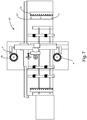
Figure 7 is a schematic view from above of a third embodiment of the machine for machining workpieces, made of wood and the like, provided with a system to manage tools, according to the invention; -
Figure 8 is a schematic view from above of a fourth embodiment of the machine for machining workpieces, made of wood and the like, provided with a system to manage tools, according to the invention. - The similar parts will be indicated in the various drawings with the same numerical references.
- With reference to
Figure 1 , the machine M for machining workpieces made in wood, plastic, metal, fiberglass, glass and the like, provided with a system to manage tools according to the invention substantially comprises a logic control unit, not shown in the drawing, equipped with a predefined machining program for operation of said machine M, amachining plane 1, for supporting workpieces to be machined, amovable carriage 2 which supports at least one machininghead 3 which actuates at least one tool-holder 32 to which is coupled atool 33 for the execution of said machining program, and at least onetool crib 4 for housing said at least one tool-holder 32. - More specifically, said
machining plane 1 has an elongate shape and extends according to a main direction X from one end to an opposite end of the machine M. - Said machining
head 3 can move with respect to saidmachining surface 1 according to three axes of movement and comprises amandrel 31 to which said tool-holder 32 is coupled. - Said mandrel 31 is actuated by an electric motor and rotated about its axis of rotation Y.
- Said tool-
holder 32 comprises acentral body 320, provided with an outer surface, afirst end 321, the so-called tool shank, which can be coupled with saidmandrel 31 by rapid coupling means, and asecond end 322 which can be coupled with saidtool 33. - On a
portion 323 of said outer surface of saidcentral body 320 of said at least one tool-holder 32, located close to saidfirst end 321 there is at least one identification mean 324 comprising information relative to the tool-holder 32. - More specifically, said identification mean 324 is a two-dimensional barcode, that is to say a matrix, also called QR Code (Quick Response Code) which is marked on the outer surface of said
portion 323 by means of various prior art laser techniques such as annealing, in which there is a change of colour of predetermined zones of saidportion 323, or engraving, in which predetermined zones of saidportion 323 are engraved. - However, the
code 324 can also be a bar code or a code of any type, without departing from the scope of protection of the invention. - The
code 324 preferably has dimensions of 5 mm x 5 mm or 6 mm x 6 mm containing alphanumeric information of at least 10 characters. - The dimensions can however vary from the dimensions indicated, without departing from the scope of protection of the invention.
- Preferably, the
code 324 is printed repeatedly every 30° on the outer surface of saidportion 323 in such a way as to facilitate the reading of thecode 324, regardless of the angular position of the tool-holder 32 inside thetool crib 4, as described in more detail below. - The
code 324 of said tool-holder 32 is associated uniquely and stably with thetool 33, and with the characteristics typical of thetool 33 such as diameter, wear, maximum speed and the like, which is coupled to said tool-holder 32 for the performance of the specific machining program, as described in more detail below. - More specifically, said
code 324 is also provided with a storage unit in which it is possible archive the data relative to the machining times of the tool, in order to program a replacement when the machining times reach a predetermined maximum threshold. - Said
machining head 3 is coupled with a reading andwriting device 5 of saidcode 324, in particular a matrix video camera, by means of a supportingstructure 51. - Said reading and
writing device 5 is also able to read the data relative to the machining time and to write, thereby updating said data. - Said supporting
structure 51 comprises apiston 52 which actuates arod 53 to which is coupled abracket 54 which supports said reading andwriting device 5. - Said supporting
structure 51 is movable along an axis Z parallel to the axis of rotation Y of saidmandrel 31. - More specifically, said supporting
rod 51 passes from a rest position in which it is vertically withdrawn or raised with respect to saidmachining plane 1, to an operating position in which saidrod 53 is lowered in such a way that said reading andwriting device 5 is positioned facing towards said tool-holder 32 coupled, in use, to saidmandrel 31, for reading thecode 324. - Said
rod 53 can also rotate about said axis Z, in such a way that saidbracket 54 and therefore said reading andwriting device 5 can be positioned facing towards a tool-holder 32 housed in saidtool crib 4. - Moreover, said supporting
structure 51 moves as one with said mandrel along the three axes of movement of themachining head 3. - Said at least one
tool crib 4 is a tool crib of the linear movable type, positioned at one of the two ends of saidmachining plane 1, which is able to translate along said axis X away from or towards saidmachining plane 1. - Said
tool crib 4 comprises a plurality ofhousings holder 32. - The association between the individual housing and the individual tool-holder is performed in a unique fashion, for the entire duration of the machining program of the workpiece, as described in detail below.
- Said machine M also comprises a logic control unit, in particular a numerical control type, in which are stored one or more programs for machining workpieces and also tables of data and specific parameters.
- More specifically, the table of tools comprises the information contained in the
code 324 of the tool-holder necessary for uniquely associating a tool-holder and a tool to be used for a specific machining program. - The table of tools also includes information concerning the exact positioning of the individual tool-
holder 32 inside the correspondinghousing tool crib 4. - With reference to
Figure 6 , according to a second embodiment the machine M' differs from said machine M solely in that it also comprises a linear fixedtool crib 4a positioned in the proximity of an opposite end with respect to that in the proximity of which is positioned said linearmovable tool crib 4 and a first 4b and/or a secondcircular tool crib 4c positioned to the side of saidmachining surface 1, one opposite the other. - The structure of said fixed
linear tool crib 4a is identical to that of the movablelinear tool crib 4. - Said first 4b and second
circular tool rib 4c also have a plurality of housings. - With reference to
Figure 7 , according to a third embodiment the machine M" differs from the second embodiment M' solely in that it comprises a second reading and writing device 5' and a third reading andwriting device 5". - Said second reading and writing device 5' is coupled movable to a second supporting rod 53' positioned along all of said linear fixed
tool crib 4a. - Said third reading and
writing device 5" is arranged in the proximity of said firstcircular tool crib 4b. - With reference to
Figure 8 , according to a fourth embodiment the machine M" differs from the second embodiment M' solely in that it comprises asecond machining head 3a substantially similar to saidfirst machining head 3, in such a way that said reading andwriting device 5 is positioned in the proximity of said firstcircular tool crib 4b and a fourth reading andwriting device 5a is positioned in the proximity of said second circular toocrib 4c. - There can also be other embodiments of the machine M in which are present different combinations of tool cribs and reading devices, without, however, departing from the scope of protection of the invention.
- The operation of the machine M described above is as follows.
- When it is necessary to carry out the machining on a workpiece made of wood, plastic, metal, fibreglass, glass and the like, this is positioned on said
machining plane 1 and a machining program stored in the logic control unit is selected. - Before staring the machining program it is necessary to perform a step or mapping the tools housed in the tool cribs, available for the machining, in order to create a stable association between tool-holder and tool during the entire machining and also for the subsequent machining programs.
- The mapping step is only repeated when it is necessary to modify the association between tool-holder and tool.
- Said reading and
writing device 5 is moved by saidmachining head 3 and said supportingstructure 51 in such a way as to be positioned in the proximity of saidtool crib 4, at a suitable distance for the reading of saidcode 324. - Said reading and
writing device 5 carries out the reading, according to a pre-set reading order, of eachcode 324 of each tool-holder 32 housed in therespective housing tool crib 4. - Said reading and
writing device 5 also reads the data relative to the machining time of the tool and, if necessary, updates it. - Said reading and
writing device 5 then sends the information contained in eachcode 324 to said logic control unit which completes the tool tables, in such a way that all the tools necessary to perform the machining program selected and the corresponding position inside thetool crib 4 are mapped, and for programming the replacement of the tool, if it has exceeded a predetermined machining time threshold. - When the machining of the work-pieces starts, the tool-
holder 32, and, therefore, thetool 33 coupled with it, are automatically coupled with saidmandrel 31, for performing the selected machining program. - In a second control step, said reading and
writing device 5 performs a second reading of saidcode 324 present on the tool-holder 32 coupled with saidmandrel 31, sends the information to said logic control unit which makes a comparison between the information received in the mapping step and the information received in said second control step. - Said reading step occurs whether said
portion 323 is fixed or in rotation. - If the information coincides, that is to say, if the tool to be loaded in the tool-holder complies with the correct association, the machining starts, otherwise the logic control unit stops the machine M since the
tool 33 coupled with themandrel 31 is not suitable for the execution of the machining program selected. - The operation of the further embodiments M', M" and M'" differs with respect to the operation described above relative to the machine M solely with respect to a step for verifying the type of tool crib present in the machine.
- Before carrying out the mapping step, a step is performed for verifying the type of tool crib and the number of tool cribs present in the machine M.
- More specifically, the logic control unit of the machine stores the types of tool cribs present in the machine.
- The type of tool crib is known to the logic control unit and the reading and
writing device 5 moves according to the commands received from the logic control unit. - As is apparent from the above description, the machine according to the invention allows a fast mapping of the tools present in the tool cribs to be performed, whatever the type of tool crib, and also allows the exact coupling between the mandrel and the tool necessary for the execution of a selected machining program to be verified, to guarantee the safety of operation of the machine.
- This invention is described by way of example only, without limiting the scope of application, according to its preferred embodiments, but it shall be understood that the invention may be modified and/or adapted by experts in the field without thereby departing from the scope of the inventive concept, as defined in the claims herein.
Claims (15)
- A machine (M, M', M", M"') for machining workpieces made of wood, plastic, metal, fibreglass, glass and the like, comprising:a logic control unit provided with at least one predetermined program for machining said workpieces;at least one tool-holder (32), to which a tool (33) can be coupled for machining said workpieces according to said machining program, said tool-holder (32) being provided with at least one identification means (324) comprising information;at least one tool crib (4, 4a, 4b, 4c) for housing said at least one tool-holder (32), when not in use;said machine (M, M', M", M"') being characterisedin that it comprises a device (5, 5', 5") for reading and writing said information comprised in said at least one said identification means (324) of said at least one tool-holder (32), designed to detect said information and send it to said logic control unit for determining the association and the coupling between said tool (33) and said at least one tool-holder (32) necessary for the execution of the machining program by said tool (33) coupled to said at least one tool-holder (32);in that said information comprised in said at least one identification means (324) also comprises machining data of said tool (33), said reading and writing device (5, 5', 5") being able to update said machining data of said tool (33);and in that said reading and writing device (5, 5', 5") is movable with respect to said tool crib (4, 4a, 4b, 4c).
- The machine (M, M', M", M"') according to the preceding claim, characterised
in that said at least one tool-holder (32) comprises a central body (320) provided with an outer surface, a first end (321) for coupling with said machine (M, M', M", M"') and a second end (322) for coupling with said tool (33), and;
in that said identification means (324) is arranged on a portion (323) of said outer surface of said central body (320). - The machine (M, M', M", M"') according to any one of the preceding claims, characterised in that said tool-holder (32) comprises a plurality of identification means (324).
- The machine (M, M', M", M"') according to any one of the preceding claims, characterised in that said identification means (324) is a QR code or a bar code.
- The machine (M, M', M", M"') according to the preceding claim, characterised in that said at least one code (324) is affixed repeatedly on said portion (323) of said outer surface of said central body (320).
- The machine (M, M', M", M"') according to the preceding claim, characterised in that said reading and writing device (5, 5', 5") of said at least one code (324) is an optical device.
- The machine (M, M', M", M"') according to any one of the preceding claims, characterised
in that it comprises at least one movable machining head (3) to which said at least one tool-holder (32) can be coupled by means of a mandrel (31), and
in that said reading and writing device (5) is arranged on said machining head (3). - The machine (M, M', M", M"') according to the preceding claim, characterised in that said reading and writing device (5) is coupled to said machining head (3) by means of a support structure (51) movable integrally with said machining head (3).
- The machine (M, M') according to any one of the preceding claims, characterised in that said at least one tool crib (4) is a linear movable tool crib.
- The machine (M") according to any one of claims 1 to 6, characterised
in that said at least one tool crib (4a) is of a fixed linear type, and
in that said reading and writing device (5') is arranged in the proximity of said tool crib (4a) and it is movable along it. - The machine (M', M", M"') according to any one of claims 1 to 8, characterised in that said at least one tool crib (4b, 4c) is a circular or elliptical tool crib.
- The machine (M', M", M"') according to any one of claims 1 to 8, characterised in that it comprises at least one movable linear tool crib (4) and at least one circular or elliptical tool crib (4b).
- The machine (M', M", M"') according to any one of claims 1 to 8, characterised in that it comprises at least one movable linear tool crib (4) and a first (4b) and a second (4c) circular tool crib.
- The machine (M") according to the preceding claims, characterised in that it comprises a further reading and writing device (5").
- An operating method of a machine (M, M', M", M"') for machining workpieces made in wood, plastic, metal, fiberglass, glass and the like, of the type comprising a logic control unit provided with at least one predetermined program for machining said workpieces, a machining head to which at least one tool-holder (32) can be coupled, to which a tool (33) can be coupled for machining said workpieces according to said machining program, said tool-holder (32) being provided with at least one identification means (324) comprising information, at least one tool crib (4, 4a, 4b, 4c) for housing said at least one tool-holder (32), when not in use, characterised in that it comprises the following steps:a. selecting a machining program stored in the logic control unit;b. providing a reading and writing device (5) for reading said information comprised in said identification means (324) of each of tool-holder (32), reading said information and sending it to said logic control unit;c. depending on the information detected in said step b., mapping the tool holders (32) housed in the tool cribs (4, 4a, 4b, 4c), in particular associating to each tool-holder (32), necessary for the execution of the machining program, the position occupied in said at least one tool crib (4, 4a, 4b, 4c);d. coupling to said machining head the tool-holder (32) necessary for the execution of the machining program;e. performing a reading of the information of said identification means (324) of the tool-holder (32) coupled to the machining head in said step d.;f. comparing said information read in said step b. with said information read in said step e.;g. if said information compared in said step f. matches, executing the machining program, if said information does not match, not starting the machining program.
Applications Claiming Priority (1)
| Application Number | Priority Date | Filing Date | Title |
|---|---|---|---|
| IT201700146829 | 2017-12-20 |
Publications (1)
| Publication Number | Publication Date |
|---|---|
| EP3501729A1 true EP3501729A1 (en) | 2019-06-26 |
Family
ID=61868724
Family Applications (1)
| Application Number | Title | Priority Date | Filing Date |
|---|---|---|---|
| EP18212727.4A Pending EP3501729A1 (en) | 2017-12-20 | 2018-12-14 | Machine for machining workpieces, provided with a system to manage tools, and operating method thereof |
Country Status (1)
| Country | Link |
|---|---|
| EP (1) | EP3501729A1 (en) |
Cited By (3)
| Publication number | Priority date | Publication date | Assignee | Title |
|---|---|---|---|---|
| IT202000017536A1 (en) * | 2020-07-20 | 2022-01-20 | Scm Group Spa | MACHINE FOR PROCESSING WOODEN AND SIMILAR PIECES, EQUIPPED WITH A TOOL RECOGNITION SYSTEM AND TOOL RECOGNITION SYSTEM. |
| US11378493B1 (en) | 2020-12-24 | 2022-07-05 | Industrial Technology Research Institute | Method for motion test and control host of movable machinery |
| EP4364916A1 (en) * | 2022-11-02 | 2024-05-08 | SCM Group S.p.A. | Control system for a workpiece machining machine, associated machine, and operating method of the machine |
Citations (2)
| Publication number | Priority date | Publication date | Assignee | Title |
|---|---|---|---|---|
| WO1994002284A1 (en) * | 1992-07-28 | 1994-02-03 | Tulon Co. | Method and apparatus for tool management |
| EP1746530A1 (en) * | 2005-07-20 | 2007-01-24 | Homag Holzbearbeitungssysteme AG | Apparatus for the identification of tools |
-
2018
- 2018-12-14 EP EP18212727.4A patent/EP3501729A1/en active Pending
Patent Citations (2)
| Publication number | Priority date | Publication date | Assignee | Title |
|---|---|---|---|---|
| WO1994002284A1 (en) * | 1992-07-28 | 1994-02-03 | Tulon Co. | Method and apparatus for tool management |
| EP1746530A1 (en) * | 2005-07-20 | 2007-01-24 | Homag Holzbearbeitungssysteme AG | Apparatus for the identification of tools |
Cited By (4)
| Publication number | Priority date | Publication date | Assignee | Title |
|---|---|---|---|---|
| IT202000017536A1 (en) * | 2020-07-20 | 2022-01-20 | Scm Group Spa | MACHINE FOR PROCESSING WOODEN AND SIMILAR PIECES, EQUIPPED WITH A TOOL RECOGNITION SYSTEM AND TOOL RECOGNITION SYSTEM. |
| EP3943237A1 (en) * | 2020-07-20 | 2022-01-26 | SCM Group S.p.A. | Machine for working wooden workpieces and the like, provided with a system for recognizing tools and system for recognizing tools |
| US11378493B1 (en) | 2020-12-24 | 2022-07-05 | Industrial Technology Research Institute | Method for motion test and control host of movable machinery |
| EP4364916A1 (en) * | 2022-11-02 | 2024-05-08 | SCM Group S.p.A. | Control system for a workpiece machining machine, associated machine, and operating method of the machine |
Similar Documents
| Publication | Publication Date | Title |
|---|---|---|
| EP3501729A1 (en) | Machine for machining workpieces, provided with a system to manage tools, and operating method thereof | |
| US5595560A (en) | Die management method for punch press | |
| CN102540970B (en) | The control method of lathe and lathe | |
| KR102046577B1 (en) | Machine tool | |
| CN102139461B (en) | Machine tool | |
| CN203863413U (en) | Tool changing system | |
| CN101546184A (en) | Machining simulation apparatus | |
| JP6322896B2 (en) | Machine Tools | |
| CN105246646A (en) | Micro turning machine | |
| US10359758B2 (en) | Tool information read/write device and machine tool having the same | |
| JP3186213B2 (en) | Tool breakage detection method | |
| ES2535846B2 (en) | Procedure for changing tool and machine tool with tool changer. | |
| US6688352B2 (en) | Multi-axis work center, for multiple production, in particular for wood working | |
| US20190202017A1 (en) | Selecting device, selecting method, and program | |
| US10343246B1 (en) | Automated machining apparatus having a workpiece holder with a rotatable turret that holds multiple workpieces | |
| US20190077185A1 (en) | Method and apparatus with rotating tool changer for automated multiple sides workpiece machining | |
| US20210101237A1 (en) | Tool Changing System of a Machining Center and Method for Controlling the Same | |
| JP2019051571A (en) | Processing device | |
| EP3943237A1 (en) | Machine for working wooden workpieces and the like, provided with a system for recognizing tools and system for recognizing tools | |
| EP3235591B1 (en) | Tool changer, machine tool, and method for changing tool | |
| JPS62297079A (en) | Automatic inking graded list robot system | |
| EP3939728A1 (en) | Machine for working workpieces provided with an improved exit station | |
| US20230415291A1 (en) | Machine tool | |
| JP3521977B2 (en) | Tool changer | |
| US20220253036A1 (en) | Tool information setting device and machine tool |
Legal Events
| Date | Code | Title | Description |
|---|---|---|---|
| PUAI | Public reference made under article 153(3) epc to a published international application that has entered the european phase |
Free format text: ORIGINAL CODE: 0009012 |
|
| STAA | Information on the status of an ep patent application or granted ep patent |
Free format text: STATUS: THE APPLICATION HAS BEEN PUBLISHED |
|
| AK | Designated contracting states |
Kind code of ref document: A1 Designated state(s): AL AT BE BG CH CY CZ DE DK EE ES FI FR GB GR HR HU IE IS IT LI LT LU LV MC MK MT NL NO PL PT RO RS SE SI SK SM TR |
|
| AX | Request for extension of the european patent |
Extension state: BA ME |
|
| STAA | Information on the status of an ep patent application or granted ep patent |
Free format text: STATUS: REQUEST FOR EXAMINATION WAS MADE |
|
| 17P | Request for examination filed |
Effective date: 20191219 |
|
| RBV | Designated contracting states (corrected) |
Designated state(s): AL AT BE BG CH CY CZ DE DK EE ES FI FR GB GR HR HU IE IS IT LI LT LU LV MC MK MT NL NO PL PT RO RS SE SI SK SM TR |
|
| STAA | Information on the status of an ep patent application or granted ep patent |
Free format text: STATUS: EXAMINATION IS IN PROGRESS |
|
| 17Q | First examination report despatched |
Effective date: 20220420 |
|
| P01 | Opt-out of the competence of the unified patent court (upc) registered |
Effective date: 20230518 |
|
| GRAP | Despatch of communication of intention to grant a patent |
Free format text: ORIGINAL CODE: EPIDOSNIGR1 |
|
| STAA | Information on the status of an ep patent application or granted ep patent |
Free format text: STATUS: GRANT OF PATENT IS INTENDED |
|
| INTG | Intention to grant announced |
Effective date: 20240319 |
|
| RIN1 | Information on inventor provided before grant (corrected) |
Inventor name: ANTONELLI, MARCO |