EP3499279A1 - Optical filters - Google Patents
Optical filters Download PDFInfo
- Publication number
- EP3499279A1 EP3499279A1 EP18211892.7A EP18211892A EP3499279A1 EP 3499279 A1 EP3499279 A1 EP 3499279A1 EP 18211892 A EP18211892 A EP 18211892A EP 3499279 A1 EP3499279 A1 EP 3499279A1
- Authority
- EP
- European Patent Office
- Prior art keywords
- filter
- component
- optical
- layers
- approximately
- Prior art date
- Legal status (The legal status is an assumption and is not a legal conclusion. Google has not performed a legal analysis and makes no representation as to the accuracy of the status listed.)
- Withdrawn
Links
- 230000003287 optical effect Effects 0.000 title claims abstract description 174
- 239000000758 substrate Substances 0.000 claims abstract description 76
- 238000000926 separation method Methods 0.000 claims abstract description 7
- 230000003595 spectral effect Effects 0.000 claims description 67
- 238000000034 method Methods 0.000 claims description 47
- 239000006096 absorbing agent Substances 0.000 claims description 35
- 239000000463 material Substances 0.000 claims description 32
- VYPSYNLAJGMNEJ-UHFFFAOYSA-N Silicium dioxide Chemical compound O=[Si]=O VYPSYNLAJGMNEJ-UHFFFAOYSA-N 0.000 claims description 30
- 238000004544 sputter deposition Methods 0.000 claims description 26
- 238000000206 photolithography Methods 0.000 claims description 16
- 238000000576 coating method Methods 0.000 claims description 15
- 239000000377 silicon dioxide Substances 0.000 claims description 15
- 239000011248 coating agent Substances 0.000 claims description 14
- 230000007704 transition Effects 0.000 claims description 11
- ZKATWMILCYLAPD-UHFFFAOYSA-N niobium pentoxide Inorganic materials O=[Nb](=O)O[Nb](=O)=O ZKATWMILCYLAPD-UHFFFAOYSA-N 0.000 claims description 8
- URLJKFSTXLNXLG-UHFFFAOYSA-N niobium(5+);oxygen(2-) Chemical compound [O-2].[O-2].[O-2].[O-2].[O-2].[Nb+5].[Nb+5] URLJKFSTXLNXLG-UHFFFAOYSA-N 0.000 claims description 8
- TWNQGVIAIRXVLR-UHFFFAOYSA-N oxo(oxoalumanyloxy)alumane Chemical compound O=[Al]O[Al]=O TWNQGVIAIRXVLR-UHFFFAOYSA-N 0.000 claims description 8
- BPUBBGLMJRNUCC-UHFFFAOYSA-N oxygen(2-);tantalum(5+) Chemical compound [O-2].[O-2].[O-2].[O-2].[O-2].[Ta+5].[Ta+5] BPUBBGLMJRNUCC-UHFFFAOYSA-N 0.000 claims description 8
- PBCFLUZVCVVTBY-UHFFFAOYSA-N tantalum pentoxide Inorganic materials O=[Ta](=O)O[Ta](=O)=O PBCFLUZVCVVTBY-UHFFFAOYSA-N 0.000 claims description 8
- 150000002290 germanium Chemical class 0.000 claims description 7
- 235000012239 silicon dioxide Nutrition 0.000 claims description 6
- 150000003376 silicon Chemical class 0.000 claims description 5
- 239000002210 silicon-based material Substances 0.000 claims description 5
- GWEVSGVZZGPLCZ-UHFFFAOYSA-N Titan oxide Chemical compound O=[Ti]=O GWEVSGVZZGPLCZ-UHFFFAOYSA-N 0.000 claims description 4
- 229910052732 germanium Inorganic materials 0.000 claims description 4
- GNPVGFCGXDBREM-UHFFFAOYSA-N germanium atom Chemical compound [Ge] GNPVGFCGXDBREM-UHFFFAOYSA-N 0.000 claims description 4
- ORUIBWPALBXDOA-UHFFFAOYSA-L magnesium fluoride Chemical compound [F-].[F-].[Mg+2] ORUIBWPALBXDOA-UHFFFAOYSA-L 0.000 claims description 4
- 238000001514 detection method Methods 0.000 claims description 3
- 239000010410 layer Substances 0.000 description 134
- UFHFLCQGNIYNRP-UHFFFAOYSA-N Hydrogen Chemical compound [H][H] UFHFLCQGNIYNRP-UHFFFAOYSA-N 0.000 description 10
- 239000001257 hydrogen Substances 0.000 description 9
- 229910052739 hydrogen Inorganic materials 0.000 description 9
- 238000000151 deposition Methods 0.000 description 7
- 238000010586 diagram Methods 0.000 description 7
- 239000000853 adhesive Substances 0.000 description 6
- 230000001070 adhesive effect Effects 0.000 description 6
- 230000008021 deposition Effects 0.000 description 6
- 239000011521 glass Substances 0.000 description 5
- XKRFYHLGVUSROY-UHFFFAOYSA-N Argon Chemical compound [Ar] XKRFYHLGVUSROY-UHFFFAOYSA-N 0.000 description 4
- 238000001228 spectrum Methods 0.000 description 4
- 238000005516 engineering process Methods 0.000 description 3
- 238000001914 filtration Methods 0.000 description 3
- 238000004519 manufacturing process Methods 0.000 description 3
- 229920002120 photoresistant polymer Polymers 0.000 description 3
- 229910000530 Gallium indium arsenide Inorganic materials 0.000 description 2
- 229910000577 Silicon-germanium Inorganic materials 0.000 description 2
- KXNLCSXBJCPWGL-UHFFFAOYSA-N [Ga].[As].[In] Chemical compound [Ga].[As].[In] KXNLCSXBJCPWGL-UHFFFAOYSA-N 0.000 description 2
- 238000001994 activation Methods 0.000 description 2
- 230000004913 activation Effects 0.000 description 2
- 238000000137 annealing Methods 0.000 description 2
- 229910052786 argon Inorganic materials 0.000 description 2
- 230000000903 blocking effect Effects 0.000 description 2
- 238000004891 communication Methods 0.000 description 2
- 230000001419 dependent effect Effects 0.000 description 2
- 238000005530 etching Methods 0.000 description 2
- 239000007789 gas Substances 0.000 description 2
- 239000011261 inert gas Substances 0.000 description 2
- 210000001503 joint Anatomy 0.000 description 2
- -1 m. For example Substances 0.000 description 2
- 238000000059 patterning Methods 0.000 description 2
- 239000004593 Epoxy Substances 0.000 description 1
- LEVVHYCKPQWKOP-UHFFFAOYSA-N [Si].[Ge] Chemical compound [Si].[Ge] LEVVHYCKPQWKOP-UHFFFAOYSA-N 0.000 description 1
- 238000010521 absorption reaction Methods 0.000 description 1
- 238000003491 array Methods 0.000 description 1
- 230000008859 change Effects 0.000 description 1
- 230000000295 complement effect Effects 0.000 description 1
- 150000002431 hydrogen Chemical class 0.000 description 1
- 238000003384 imaging method Methods 0.000 description 1
- 230000000977 initiatory effect Effects 0.000 description 1
- 230000010354 integration Effects 0.000 description 1
- 238000005259 measurement Methods 0.000 description 1
- 239000000203 mixture Substances 0.000 description 1
- 238000012986 modification Methods 0.000 description 1
- 230000004048 modification Effects 0.000 description 1
- 229910052756 noble gas Inorganic materials 0.000 description 1
- 238000000678 plasma activation Methods 0.000 description 1
- 239000011241 protective layer Substances 0.000 description 1
- 238000002310 reflectometry Methods 0.000 description 1
- 239000004065 semiconductor Substances 0.000 description 1
- 238000012360 testing method Methods 0.000 description 1
- 239000010409 thin film Substances 0.000 description 1
- 238000001429 visible spectrum Methods 0.000 description 1
Images


Classifications
-
- G—PHYSICS
- G02—OPTICS
- G02B—OPTICAL ELEMENTS, SYSTEMS OR APPARATUS
- G02B5/00—Optical elements other than lenses
- G02B5/20—Filters
-
- G—PHYSICS
- G01—MEASURING; TESTING
- G01J—MEASUREMENT OF INTENSITY, VELOCITY, SPECTRAL CONTENT, POLARISATION, PHASE OR PULSE CHARACTERISTICS OF INFRARED, VISIBLE OR ULTRAVIOLET LIGHT; COLORIMETRY; RADIATION PYROMETRY
- G01J1/00—Photometry, e.g. photographic exposure meter
- G01J1/02—Details
- G01J1/0214—Constructional arrangements for removing stray light
-
- G—PHYSICS
- G02—OPTICS
- G02B—OPTICAL ELEMENTS, SYSTEMS OR APPARATUS
- G02B5/00—Optical elements other than lenses
- G02B5/20—Filters
- G02B5/208—Filters for use with infrared or ultraviolet radiation, e.g. for separating visible light from infrared and/or ultraviolet radiation
-
- G—PHYSICS
- G01—MEASURING; TESTING
- G01J—MEASUREMENT OF INTENSITY, VELOCITY, SPECTRAL CONTENT, POLARISATION, PHASE OR PULSE CHARACTERISTICS OF INFRARED, VISIBLE OR ULTRAVIOLET LIGHT; COLORIMETRY; RADIATION PYROMETRY
- G01J1/00—Photometry, e.g. photographic exposure meter
- G01J1/02—Details
- G01J1/04—Optical or mechanical part supplementary adjustable parts
- G01J1/0488—Optical or mechanical part supplementary adjustable parts with spectral filtering
- G01J1/0492—Optical or mechanical part supplementary adjustable parts with spectral filtering using at least two different filters
-
- G—PHYSICS
- G01—MEASURING; TESTING
- G01J—MEASUREMENT OF INTENSITY, VELOCITY, SPECTRAL CONTENT, POLARISATION, PHASE OR PULSE CHARACTERISTICS OF INFRARED, VISIBLE OR ULTRAVIOLET LIGHT; COLORIMETRY; RADIATION PYROMETRY
- G01J3/00—Spectrometry; Spectrophotometry; Monochromators; Measuring colours
- G01J3/02—Details
- G01J3/0262—Constructional arrangements for removing stray light
-
- G—PHYSICS
- G02—OPTICS
- G02B—OPTICAL ELEMENTS, SYSTEMS OR APPARATUS
- G02B1/00—Optical elements characterised by the material of which they are made; Optical coatings for optical elements
- G02B1/04—Optical elements characterised by the material of which they are made; Optical coatings for optical elements made of organic materials, e.g. plastics
-
- G—PHYSICS
- G02—OPTICS
- G02B—OPTICAL ELEMENTS, SYSTEMS OR APPARATUS
- G02B1/00—Optical elements characterised by the material of which they are made; Optical coatings for optical elements
- G02B1/10—Optical coatings produced by application to, or surface treatment of, optical elements
- G02B1/11—Anti-reflection coatings
-
- G—PHYSICS
- G02—OPTICS
- G02B—OPTICAL ELEMENTS, SYSTEMS OR APPARATUS
- G02B5/00—Optical elements other than lenses
- G02B5/20—Filters
- G02B5/201—Filters in the form of arrays
-
- G—PHYSICS
- G02—OPTICS
- G02B—OPTICAL ELEMENTS, SYSTEMS OR APPARATUS
- G02B5/00—Optical elements other than lenses
- G02B5/20—Filters
- G02B5/28—Interference filters
- G02B5/281—Interference filters designed for the infrared light
-
- G—PHYSICS
- G02—OPTICS
- G02B—OPTICAL ELEMENTS, SYSTEMS OR APPARATUS
- G02B5/00—Optical elements other than lenses
- G02B5/20—Filters
- G02B5/28—Interference filters
- G02B5/281—Interference filters designed for the infrared light
- G02B5/282—Interference filters designed for the infrared light reflecting for infrared and transparent for visible light, e.g. heat reflectors, laser protection
-
- G—PHYSICS
- G02—OPTICS
- G02B—OPTICAL ELEMENTS, SYSTEMS OR APPARATUS
- G02B6/00—Light guides; Structural details of arrangements comprising light guides and other optical elements, e.g. couplings
- G02B6/10—Light guides; Structural details of arrangements comprising light guides and other optical elements, e.g. couplings of the optical waveguide type
- G02B6/12—Light guides; Structural details of arrangements comprising light guides and other optical elements, e.g. couplings of the optical waveguide type of the integrated circuit kind
- G02B6/12007—Light guides; Structural details of arrangements comprising light guides and other optical elements, e.g. couplings of the optical waveguide type of the integrated circuit kind forming wavelength selective elements, e.g. multiplexer, demultiplexer
-
- G—PHYSICS
- G03—PHOTOGRAPHY; CINEMATOGRAPHY; ANALOGOUS TECHNIQUES USING WAVES OTHER THAN OPTICAL WAVES; ELECTROGRAPHY; HOLOGRAPHY
- G03F—PHOTOMECHANICAL PRODUCTION OF TEXTURED OR PATTERNED SURFACES, e.g. FOR PRINTING, FOR PROCESSING OF SEMICONDUCTOR DEVICES; MATERIALS THEREFOR; ORIGINALS THEREFOR; APPARATUS SPECIALLY ADAPTED THEREFOR
- G03F7/00—Photomechanical, e.g. photolithographic, production of textured or patterned surfaces, e.g. printing surfaces; Materials therefor, e.g. comprising photoresists; Apparatus specially adapted therefor
- G03F7/0005—Production of optical devices or components in so far as characterised by the lithographic processes or materials used therefor
- G03F7/0007—Filters, e.g. additive colour filters; Components for display devices
-
- G—PHYSICS
- G01—MEASURING; TESTING
- G01J—MEASUREMENT OF INTENSITY, VELOCITY, SPECTRAL CONTENT, POLARISATION, PHASE OR PULSE CHARACTERISTICS OF INFRARED, VISIBLE OR ULTRAVIOLET LIGHT; COLORIMETRY; RADIATION PYROMETRY
- G01J3/00—Spectrometry; Spectrophotometry; Monochromators; Measuring colours
- G01J3/12—Generating the spectrum; Monochromators
- G01J2003/1213—Filters in general, e.g. dichroic, band
-
- G—PHYSICS
- G01—MEASURING; TESTING
- G01J—MEASUREMENT OF INTENSITY, VELOCITY, SPECTRAL CONTENT, POLARISATION, PHASE OR PULSE CHARACTERISTICS OF INFRARED, VISIBLE OR ULTRAVIOLET LIGHT; COLORIMETRY; RADIATION PYROMETRY
- G01J3/00—Spectrometry; Spectrophotometry; Monochromators; Measuring colours
- G01J3/12—Generating the spectrum; Monochromators
- G01J2003/1226—Interference filters
- G01J2003/123—Indexed discrete filters
-
- G—PHYSICS
- G02—OPTICS
- G02B—OPTICAL ELEMENTS, SYSTEMS OR APPARATUS
- G02B13/00—Optical objectives specially designed for the purposes specified below
- G02B13/14—Optical objectives specially designed for the purposes specified below for use with infrared or ultraviolet radiation
- G02B13/146—Optical objectives specially designed for the purposes specified below for use with infrared or ultraviolet radiation with corrections for use in multiple wavelength bands, such as infrared and visible light, e.g. FLIR systems
-
- G—PHYSICS
- G02—OPTICS
- G02B—OPTICAL ELEMENTS, SYSTEMS OR APPARATUS
- G02B6/00—Light guides; Structural details of arrangements comprising light guides and other optical elements, e.g. couplings
- G02B6/10—Light guides; Structural details of arrangements comprising light guides and other optical elements, e.g. couplings of the optical waveguide type
- G02B6/12—Light guides; Structural details of arrangements comprising light guides and other optical elements, e.g. couplings of the optical waveguide type of the integrated circuit kind
- G02B2006/12083—Constructional arrangements
- G02B2006/12109—Filter
-
- G—PHYSICS
- G02—OPTICS
- G02B—OPTICAL ELEMENTS, SYSTEMS OR APPARATUS
- G02B5/00—Optical elements other than lenses
- G02B5/003—Light absorbing elements
Abstract
Description
- An optical sensor device may be utilized to capture information. For example, the optical sensor device may capture information relating to a set of electromagnetic frequencies. The optical sensor device may include a set of sensor elements (e.g., optical sensors, spectral sensors, and/or image sensors) that capture the information. For example, an array of sensor elements may be utilized to capture information relating to multiple frequencies. In one example, an array of sensor elements may be utilized to capture information regarding a particular spectral range, such as a spectral range of from approximately 400 nanometers (nm) to approximately 700 nm, a spectral range of from approximately 700 nm to approximately 1100 nm, a subrange thereof, or the like. A sensor element, of the sensor element array, may be associated with a filter. The filter may include a passband associated with a first spectral range of light that is passed to the sensor element. The filter may be associated with blocking a second spectral range of light from being passed to the sensor element.
- According to some possible implementations, an optical filter may include a monolithic substrate. The optical filter may include a first component filter disposed onto a first region of the monolithic substrate. The first component filter may be a near infrared (NIR) bandpass filter. The optical filter may include a second component filter disposed onto a second region of the monolithic substrate. The second component filter may include a red-green-blue (RGB) bandpass filter. A separation between the first component filter and the second component filter may be less than approximately 50 micrometers (µm).
- The optical filter may comprise an absorber disposed at a transition zone of the optical filter, the transition zone being at an edge of the first component filter and the second component filter.
- The first component filter and the second component filter may be disposed between the absorber and the monolithic substrate.
- The absorber may be disposed between the first component filter and the second component filter.
- The absorber may be disposed between the first component filter and the monolithic substrate and between the second component filter and the monolithic substrate.
- The optical filter may further comprise an anti-reflectance coating disposed onto a surface of the monolithic substrate, such that the monolithic substrate may be disposed between the anti-reflectance coating and the first component filter and between the anti-reflectance coating and the second component filter.
- The monolithic substrate may be a glass substrate or a silica substrate.
- The first component filter and the second component filter may be disposed onto the monolithic substrate using a sputter deposition procedure.
- The first component filter and the second component filter may be disposed onto the monolithic substrate using a photolithography procedure.
- The first component filter may be associated with a first spectral range and the second component filter may be associated with a second, different spectral range.
- The first component filter may be associated with a spectral range of from approximately 700 nm to approximately 1100 nm.
- The second component filter may be associated with a spectral range of from approximately 400 nm to approximately 700 nm.
- The second component optical filter may be associated with a spectral range of from approximately 420 nm to approximately 630 nm.
- The separation between the first component filter and the second component filter is less than approximately 30 µm.
- According to some possible implementations, an optical system may include an optical filter including a plurality of component filters configured to filter an input optical signal and provide a filtered input optical signal. The plurality of component filters may be associated with two or more spectral ranges. The plurality of component filters may be disposed onto a single substrate using a photolithography procedure. An optical sensor may be configured to receive the filtered input optical signal and provide an output electrical signal.
- The filtered input optical signal may include two or more component filtered input optical signals corresponding to the two or more spectral ranges.
- The output electrical signal may be related to performing at least one of: an iris detection functionality, an iris recognition functionality, or a low-light security photography functionality.
- According to some possible implementations, a bandpass filter may include a first patterned component filter. The first patterned component filter may include a first set of filter layers associated with a first refractive index and deposited using a sputter deposition technique. The first patterned component filter may include a second set of filter layers associated with a second refractive index that is less than the first refractive index and deposited using the sputter deposition technique. The bandpass filter may include a second patterned component filter. The second patterned component filter may include a third set of filter layers associated with a third refractive index and deposited using the sputter deposition technique. The second patterned component filter may include a fourth set of filter layers associated with a fourth refractive index and deposited using the sputter deposition technique. The first component filter may be separated from the second component filter by less than approximately 30 micrometers (µm). The first component filter may be associated with a first bandpass and the second component filter is associated with a second bandpass that is different from the first bandpass.
- At least one filter layer of the first set of filter layers, the second set of filter layers, the third set of filter layers, or the fourth set of filter layers may be one of: a silicon based material, a hydrogenated silicon based material, a germanium based material, a hydrogenated germanium based material, a silicon dioxide (SiO2) material, an aluminum oxide (Al2O3) material, a titanium dioxide (TiO2) material, a niobium pentoxide (Nb2O5) material, a tantalum pentoxide (Ta2O5) material, or a magnesium fluoride (MgF2) material.
- At least one filter of the first set of filter layers, the second set of filter layers, the third set of filter layers, or the fourth set of filter layers may be annealed.
-
-
Figs. 1A-1I are diagrams of an overview of an example implementation described herein; -
Fig. 2 is a diagram of an example implementation of an optical filter described herein; -
Fig. 3 is a diagram of a system for manufacturing an optical filter described herein; and -
Fig. 4 is a diagram of characteristics relating to an optical filter described herein. - The following detailed description of example implementations refers to the accompanying drawings. The same reference numbers in different drawings may identify the same or similar elements.
- An optical sensor device may include a sensor element array of sensor elements to receive light initiating from an optical source, such as an optical transmitter, a light bulb, an ambient light source, and/or the like. The optical sensor device may utilize one or more sensor technologies, such as a complementary metal-oxide-semiconductor (CMOS) technology, a charge-coupled device (CCD) technology, and/or the like. A sensor element (e.g., an optical sensor), of the optical sensor device, may obtain information (e.g., spectral data) regarding a set of electromagnetic frequencies. The sensor element may be an indium-gallium-arsenide (InGaAs) based sensor element, a silicon germanium (SiGe) based sensor element, and/or the like.
- A sensor element may be associated with a filter that filters light to the sensor element to enable the sensor element to obtain information regarding a particular spectral range of electromagnetic frequencies. For example, the sensor element may be aligned with a filter with a passband in a spectral range of approximately 400 nanometers (nm) to approximately 700 nm, a spectral range of approximately 700 nm to approximately 1100 nm, a subrange thereof, and/or the like to cause a portion of light that is directed toward the sensor element to be filtered. A filter may include sets of dielectric layers to filter the portion of the light. For example, a filter may include dielectric filter stacks of alternating high index layers and low index layers, such as alternating layers of hydrogenated silicon (Si:H or SiH) or germanium (Ge) as a high index material and silicon dioxide (SiO2) as a low index material.
- Some sensor element arrays may be configured to receive multiple wavelengths of light. For example, for a sensor element array being used to perform iris recognition, the sensor element array may be configured to receive a first portion of light in a near infrared (NIR) spectrum and a second portion of light in a visible light spectrum (e.g., a red-green-blue (RGB) spectrum). In this case, multiple filters (e.g., an NIR passband filter and an RGB passband filter) may be disposed between the sensor element array and a subject. For example, a first filter may be disposed on a first substrate to enable NIR light to pass through the first filter and a second filter may be disposed on a second substrate to enable RGB light to pass through the second filter. In this case, the first substrate may be attached to the second substrate using an opaque adhesive to form a butt joint, and aligned to the sensor element array to enable the NIR light and the RGB light to be directed toward the sensor element array.
- However, use of multiple filters disposed onto multiple substrates and attached together may result in poor mechanical durability. For example, utilization of the adhesive to attach the first substrate to the second substrate may result in relatively poor mechanical strength as a result of part-part planarity for the first substrate and second substrate and bond line variation for the adhesive. Moreover, the utilization of an adhesive to join the first filter and the second filter may result in a spacing between the first filter and the second filter of greater than 50 micrometers (µm), greater than 100 µm, and/or the like, thereby increasing a total package size of the sensor element array and the filters.
- Some implementations, described herein, provide multiple component filters integrated onto a common substrate by applying patterned coatings to different sections of the common substrate. For example, a photolithography procedure, a sputter deposition procedure, a patterning procedure, an etching procedure, a combination thereof, and/or the like may be utilized to integrate multiple component filters onto a single, monolithic substrate to form a single optical filter with multiple passbands at multiple regions of the single optical filter. In this way, the optical filter may enable optical sensing, such as for NIR spectrum and visible spectrum combined sensing for iris recognition, low-light security photography, and/or the like. In some implementations, described herein, the optical filter may include, as component filters, an NIR bandpass filter and an infrared (IR) cut filter, an NIR bandpass filter and an RGB bandpass filter, an RGB bandpass filter and an ultraviolet (UV) bandpass filter, and/or the like.
- In this way, integration of multiple component filters onto a single, monolithic substrate may provide improved mechanical durability relative to an adhesive based butt joint. Moreover, utilizing a photolithography technique, a sputter deposition technique, a patterning technique, and/or the like to integrate the multiple component filters onto the single substrate may reduce a spacing between the component filters to less than 50 µm, less than 30 µm, less than 20 µm, less than 10 µm, and/or the like. In this way, a package size of a sensor element array including an optical filter with multiple component filters may be reduced, thereby improving miniaturization of optical sensors for iris recognition, low-light security photography, and/or the like.
-
Figs. 1A-1I are diagrams of an overview of example implementations 100-108 described herein. As shown inFig. 1A ,example implementation 100 includes asensor system 110.Sensor system 110 may be a portion of an optical system, and may provide an electrical output corresponding to a sensor determination.Sensor system 110 includes anoptical filter structure 120, which includes component filter 130-1, component filter 130-2, and an absorber 130-3 (e.g., with less than a threshold reflectivity); and anoptical sensor 140. Collectively, component filter 130-1, component filter 130-2, and absorber 130-3 may be referred to as optical filter 130. For example,optical filter structure 120 may include an optical filter 130 that performs a first passband filtering functionality for a first passband associated with component filter 130-1 and that performs a second passband filtering functionality for a second passband associated with component filter 130-2. - Although some implementations, described herein, may be described in terms of an optical filter in a sensor system, implementations described herein may be used in another type of system, may be used external to a sensor system, and/or the like.
- As further shown in
Fig. 1A , and byreference number 150, an input optical signal is directed towardoptical filter structure 120. The input optical signal may include, but is not limited to, light associated with a particular spectral range, such as a spectral range of from approximately 400 nm to approximately 700 nm, a spectral range of from approximately 420 nm to approximately 630 nm, a spectral range of from approximately 700 nm to approximately 1100 nm, a spectral range of from approximately 750 nm to approximately 950 nm, a spectral range of from approximately 400 nm to approximately 1100 nm, a sub-range thereof, and/or the like. For example, visible light and NIR light may be reflected off an iris of a subject towardoptical sensor 140, and may be filtered by optical filter 130 to provide the visible light toward a first portion ofoptical sensor 140 and NIR light toward a second portion ofoptical sensor 140. In another example, an optical transmitter may direct a spectral range of light towardoptical sensor 140 for another functionality, such as a testing functionality, a sensing functionality, a communications functionality, and/or the like. - As further shown in
Fig. 1A , and byreference number 160, a first portion of the optical signal with a first spectral range is not passed through by optical filter 130 andoptical filter structure 120. For example, dielectric filter stacks of dielectric thin film layers, which may include high index material layers and low index material layers of optical filter 130, may cause the first portion of light to be reflected in a first direction, to be absorbed, and/or the like. In this case, the first portion of light may be a threshold portion of light incident on optical filter 130 not included in a bandpass of component filters 130-1 and/or 130-2, such as greater than 95% of light not within a particular spectral range. - In some implementations, the first portion of the optical signal may include a first component portion reflected by component filter 130-1, a second component portion reflected by component filter 130-2, and a third component portion absorbed and/or reflected by absorber 130-3 (which may sometimes be termed a "mirror," a "dark mirror," and/or the like). For example, component filter 130-1 may pass visible light, and may reflect NIR light and other light of the input optical signal. In contrast, component filter 130-2 may pass NIR light, and may reflect visible light and other light of the input optical signal. Further, absorber 130-3 may absorb and suppress reflection of all spectral ranges of light, thereby reducing cross-talk between light passed by component filter 130-1 and light passed by component filter 130-2. In some implementations, an absorber, such as absorber 130-3 may be associated with absorbing a threshold percentage of light, such as greater than approximately 50%, greater than approximately 80%, greater than approximately 90%, greater than approximately 95%, greater than approximately 99%, and/or the like. A second portion and a third portion of the optical signal may be passed as a filtered input optical signal.
- As shown by reference number 170-1, the second portion of the optical signal is passed through by component filter 130-1 and
optical filter structure 120. For example, component filter 130-1 may pass through the second portion of light with a second spectral range in a second direction towardoptical sensor 140. In this case, the second portion of light may be a threshold portion of light incident on component filter 130-1 within a bandpass of component filter 130-1, such as greater than 50% of incident light in a spectral range for visible light. - As shown by reference number 170-2, the third portion of the optical signal is passed through by component filter 130-2 and
optical filter structure 120. For example, component filter 130-2 may pass through the third portion of light with a third spectral range in a third direction towardoptical sensor 140. In this case, the third portion of light may be a threshold portion of light incident on component filter 130-2 within a bandpass of component filter 130-2, such as greater than 50% of incident light in a spectral range for NIR light. In this way, a singleoptical filter structure 120 with multiple component filters 130 disposed onto the single optical filter structure 120 (e.g., using a photolithography technique) may pass multiple, different spectral ranges of light tooptical sensor 140, thereby enabling multi-spectral sensing, such as to perform NIR light and RGB light based iris recognition, low-light security photography, and/or the like. - As further shown in
Fig. 1A , based on the second portion and the third portion of the optical signal being passed tooptical sensor 140,optical sensor 140 may provide an outputelectrical signal 180 forsensor system 110, such as for use in imaging, iris recognition, low-light light sensing, detecting the presence of an object, performing a measurement, facilitating communication, and/or the like. In some implementations, another arrangement of component filters 130 andoptical sensor 140 may be utilized. For example, rather than passing the second portion and the third portion of the optical signal collinearly with the input optical signal, optical filter 130 may direct the second portion and the third portion of the optical signal in another direction toward a differently locatedoptical sensor 140. - As shown in
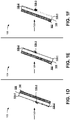
Fig. 1B , anotherexample implementation 101 includes a set of sensor elements of a sensor element array formingoptical sensor 140 and integrated into a substrate ofoptical filter structure 120. In this case, component filters 130 are disposed directly onto the substrate (e.g., using a photolithography procedure, a sputter deposition procedure, an etching procedure, a combination thereof, and/or the like). Input optical signals 150-1 and 150-2 are received at multiple different angles and first portions 160-1 and 160-2 of input optical signals 150-1 and 150-2 are reflected at multiple different angles. In this case, second portions of input optical signals 150-1 and 150-2 are passed as filtered input optical signals with multiple spectral ranges through component filters 130 to a sensor element array formingoptical sensor 140, which provides an outputelectrical signal 180. For example, the second portions of input optical signals 150-1 and 150-2 may include light with a first spectral range (e.g., visible light) passed by component filter 130-1 and light with a second spectral range (e.g., NIR light) passed by component filter 130-2. - As shown in
Fig. 1C , anotherexample implementation 102 includes a set of sensor elements of a sensor element array formingoptical sensor 140 and separated from an optical filter structure 120 (e.g., by free space in a free space optics type of optical system). In this case, component filters 130 are disposed ontooptical filter structure 120, which may be a glass substrate, a silica substrate, and/or the like. Input optical signals 150-1 and 150-2 are received at multiple different angles at optical filter 130. First portions 160-1 and 160-2 of the input optical signals 150-1 and 150-2 are reflected and second portions 170-1 and 170-2 of the input optical signals 150-1 and 150-2 are passed by component filters 130 andoptical filter structure 120. Based on receiving second portions 170-1 and 170-2, the sensor element array provides an outputelectrical signal 180. - Although some implementations, described herein, are described in terms of an NIR light passband filter and a visible light (e.g., RGB light) passband filter, other combinations of multiple spectral ranges of filters are possible, such as a first NIR light passband filter and a second NIR light passband filter, a visible light passband filter and an IR blocker filter, a visible light passband filter and an ultraviolet (UV) light passband filter, and/or the like. Similarly, although some implementations, described herein, are described in terms of two filters disposed onto a single substrate, other quantities of filters are possible, such as 3 filters, 4 filters, 10 filters, 100 filters, and/or the like.
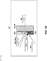
- As shown in Fig. ID, another
example implementation 103 includes another configuration for an optical filter. For example, inexample implementation 103, ananti-reflectance coating 182 is disposed onto a surface ofoptical filter structure 120. Additionally, or alternatively, absorber 130-3 is positioned such that component filters 130-1 and 130-2 cover at least a portion of absorber 130-3. In other words, absorber 130-3 is positioned between a portion of component filters 130-1 and 130-2 andoptical filter structure 120. In this case, inputoptical signal 150 is directed toward a side ofoptical filter structure 120 onto which component filters 130 are disposed. As shown in Fig. IE, in anotherexample implementation 104, inputoptical signal 150 can be directed toward another side ofoptical filter structure 120 onto whichanti-reflectance coating 182 is disposed. As shown inFig. 1F , in anotherexample implementation 105, absorber 130-3 may be disposed onto a surface of component filters 130-1 and 130-2. In other words, absorber 130-3 may cover a portion of component filters 130-1 and 130-2. In this case, inputoptical signal 150 may be directed toward ananti-reflectance coating 182 side ofoptical filter structure 120. In another example, inputoptical signal 150 may be directed to a component filters 130 side ofoptical filter structure 120. Although described herein in terms of free-space optics, example implementations described herein may be used in free-space optics, non-free-space optics, a combination of free-space optics and non-free-space optics, and/or the like. - As shown in
Fig. 1G , anotherexample implementation 106 may include component filters 130 disposed directly ontooptical sensor 140, which may formoptical filter structure 120 and may include a set of sensor elements. In this case, absorber 130-3 may be disposed under component filters 130-1 and 130-2. In other words, component filters 130-1 and 130-2 may at least partially cover absorber 130-3, which may be disposed between component filters 130-1 and 130-2 andoptical sensor 140. In this case, input optical signal is directed toward a component filters 130 side ofoptical sensor 140. As shown inFig. 1H , in anotherexample implementation 107, inputoptical signal 150 can be directed toward another side ofoptical sensor 140. In some implementations, an anti-reflectance coating may be disposed onto the other side ofoptical sensor 140, betweenoptical sensor 140 and component filters 130, onto a surface of component filters 130, and/or the like. In some implementations, absorber 130-3 may be aligned with one or more sensor elements of the set of sensor elements ofoptical sensor 140, aligned offset from one or more sensor elements, and/or the like. As shown inFig. 1I , in another example, a set ofmicrolenses 184 may be aligned with one or more sensor elements of the set of sensor elements ofoptical sensor 140. In this case, component filters 130 are disposed ontooptical filter structure 120, which is separated by free space fromoptical sensor 140 and the set of sensor elements. In some implementations, the set ofmicrolenses 184 may be disposed onto a surface ofoptical sensor 140. In some implementations, the set ofmicrolenses 184 may be disposed onto a surface of, for example,optical filter structure 120, component filters 130, and/or the like to direct light to the set of sensor elements, focus light for the set of sensor elements, and/or the like. - As indicated above,
Figs. 1A-1I are provided merely as examples. Other examples are possible and may differ from what was described with regard toFigs. 1A-1I . -
Fig. 2 is a diagram of an exampleoptical filter 200.Optical filter 200 includes afirst component filter 210, which is disposed on asubstrate 220 and includes a set of layers 230 and a set oflayers 240.Optical filter 200 includes asecond component filter 250, which is disposed onsubstrate 220 and includes a set oflayers 260 and a set oflayers 270. In some implementations,optical filter 200 includes anabsorber 280 and/or a filter layer 290 (e.g., an anti-reflectance coating). -
Component filter 210 includes a set of optical filter layers. For example,component filter 210 includes a first set of layers 230-1 through 230-N(N ≥ 1) (e.g., high refractive index layers (H layers)) and a second set of layers 240-1 through 240-(N+1) (e.g., low refractive index layers (L layers)). In some implementations, layers 230 and 240 may be arranged in a particular order, such as an (H-L) m (m ≥ 1) order, an (H-L) m -H order, an (L-H) m order, an L-(H-L) m order, and/or the like. For example, as shown, layers 230 and 240 are positioned in an (H-L) n -H order with an H layer disposed at a surface ofoptical filter 200 and an H layer contiguous to a surface ofsubstrate 220. In some implementations, one or more other layers may be included inoptical filter 200, such as one or more protective layers, one or more layers to provide one or more other filtering functionalities (e.g., a blocker, an anti-reflection coating, etc.), and/or the like. - Layers 230 may include a set of H layers, such as a material with a refractive index greater than the refractive index of the L layers, a refractive index greater than 2.0, a refractive index greater than 3.0, a refractive index greater than 4.0, a refractive index greater than 4.5, a refractive index greater the 4.6, and/or the like, over a particular spectral range (e.g., the spectral range of approximately 400 nm to approximately 700 nm, the spectral range of approximately 420 nm to approximately 630 nm, and/or the like). In some implementations, layers 230 may include hydrogenated germanium layers, hydrogenated silicon layers, annealed hydrogenated germanium, and/or the like.
-
Layers 240 may include a set of L layers, such as a set of silicon dioxide (SiO2) layers, a set of aluminum oxide (Al2O3) layers, a set of titanium dioxide (TiO2) layers, a set of niobium pentoxide (Nb2O5) layers, a set of tantalum pentoxide (Ta2O5) layers, a set of magnesium fluoride (MgF2) layers, and/or the like. In this case, layers 240 may be selected to include a refractive index lower than that of the layers 230 over, for example, a particular spectral range (e.g., the spectral range of approximately 400 nm to approximately 700 nm, the spectral range of approximately 420 nm to approximately 630 nm, and/or the like). For example, layers 240 may be selected to be associated with a refractive index of less than 3 over the particular spectral range. - In another example, layers 240 may be selected to be associated with a refractive index of less than 2.5 over the particular spectral range (e.g., the spectral range of approximately 400 nm to approximately 700 nm, the spectral range of approximately 420 nm to approximately 630 nm, and/or the like). In another example, layers 240 may be selected to be associated with a refractive index of less than 2 over the particular spectral range (e.g., the spectral range of approximately 400 nm to approximately 700 nm, the spectral range of approximately 420 nm to approximately 630 nm, and/or the like). In another example, layers 240 may be selected to be associated with a refractive index of less than 1.5 over the particular spectral range (e.g., the spectral range of approximately 400 nm to approximately 700 nm, the spectral range of approximately 420 nm to approximately 630 nm, and/or the like). In some implementations, the particular material may be selected for
layers 240 based on a desired width of an out-of-band blocking spectral range, a desired center-wavelength shift associated with a change of angle of incidence, and/or the like. - In some implementations,
component filter 210 may be associated with a particular quantity of layers, m. For example,component filter 210 may include approximately 20 layers of alternating H layers and L layers. In another example,component filter 210 may be associated with another quantity of layers, such as a range of 2 layers to 100 layers, a range of 4 layers to 50 layers, and/or the like. In some implementations, each layer ofcomponent filter 210 may be associated with a particular thickness. For example, layers 230 and 240 may each be associated with a thickness of between approximately 5 nm and approximately 2000 nm, resulting incomponent filter 210 being associated with a thickness of between approximately 0.2 µm and 100 µm, between approximately 0.5 µm and 20 µm, between approximately 4 µm and 7 µm, and/or the like. - In some implementations, layers 230 and 240 may be associated with multiple thicknesses, such as a first thickness for layers 230 and a second thickness for
layers 240, a first thickness for a first subset of layers 230 and a second thickness for a second subset of layers 230, a first thickness for a first subset oflayers 240 and a second thickness for a second subset oflayers 240, and/or the like. In this case, a layer thickness and/or a quantity of layers may be selected based on an intended set of optical characteristics, such as an intended passband, an intended transmissivity, and/or the like. For example, the layer thickness and/or the quantity of layers may be selected to permitoptical filter 200 to be utilized for a spectral range of approximately 1100 nm to approximately 2000 nm, at a center wavelength of approximately 1550 nm, and/or the like. -
Component filter 250 includes a set of optical filter layers. For example,component filter 250 includes a first set of layers 260-1 through 260-K (K ≥ 1) (e.g., H layers) and a second set of layers 270-1 through 270-K (e.g., L layers). In some implementations, layers 260 and 270 may be arranged in a particular order, such as an (H-L) m (k ≥ 1) order.Layers 260 may include a set of H layers, such as a material with a refractive index greater than the refractive index of the L layers, a refractive index greater than 2.0, a refractive index greater than 3.0, a refractive index greater than 4.0, a refractive index greater than 4.5, a refractive index greater the 4.6, and/or the like, over a particular spectral range (e.g., the spectral range of approximately 400 nm to approximately 700 nm, the spectral range of approximately 420 nm to approximately 630 nm, and/or the like). In some implementations, layers 260 may include hydrogenated germanium layers, hydrogenated silicon layers, annealed hydrogenated germanium, and/or the like. -
Layers 270 may include a set of L layers, such as a set of silicon dioxide (SiO2) layers, a set of aluminum oxide (Al2O3) layers, a set of titanium dioxide (TiO2) layers, a set of niobium pentoxide (Nb2O5) layers, a set of tantalum pentoxide (Ta2O5) layers, a set of magnesium fluoride (MgF2) layers, and/or the like. In this case, layers 270 may be selected to include a refractive index lower than that of thelayers 260 over, for example, a particular spectral range (e.g., the spectral range of approximately 400 nm to approximately 700 nm, the spectral range of approximately 420 nm to approximately 630 nm, and/or the like). For example, layers 270 may be selected to be associated with a refractive index of less than 3 over the particular spectral range. In some implementations, a quantity oflayers 260 and/orlayers 270 may be different from a quantity of layers 230 and/orlayers 240, the same as a quantity of layers 230 and/orlayers 240, and/or the like. In some implementations, a thickness oflayers 260 and/orlayers 270 may be different from a thickness of layers 230 and/orlayers 240, the same as a thickness of layers 230 and/orlayers 240, and/or the like. - In some implementations, component filters 210 and 250 may be fabricated using a sputtering procedure and a photolithography procedure. For example,
component filter 210 may be fabricated using a pulsed-magnetron based sputtering procedure to sputter alternatinglayers 230 and 240 on a glass substrate. A photolithography procedure and a lift-off procedure may be used to removelayers 230 and 240 from a portion ofsubstrate 220 that is to be used forcomponent filter 250, forabsorber 280, and/or the like. Similarly,component filter 250 may be fabricated using a pulsed-magnetron based sputtering procedure to sputter alternatinglayers substrate 220 and ontocomponent filter 210. In this case, the photolithography procedure and the lift-off procedure are used to removelayers component filter 210, resulting incomponent filter 210 andcomponent filter 250 being approximately contiguous (e.g., contiguous, separated byabsorber 280, and/or the like). Similarly,absorber 280 may be fabricated using a pulsed-magnetron based sputtering procedure to sputter layers ofabsorber 280 ontosubstrate 220 and onto component filters 210 and 250. In this case, the photolithography procedure and the lift-off procedure are used to remove layers ofabsorber 280 fromcomponent filters component filters common substrate 220 withabsorber 280 covering a transition zone betweencomponent filters - In some implementations, a particular ordering of sputter deposition and lift-off may be performed. For example, an NIR bandpass filter (e.g., component filter 210) may be deposited followed by an RGB bandpass filter (e.g., component filter 250) and followed by an absorber (e.g., absorber 280). Similarly, an absorber may be deposited followed by an RGB bandpass filter and followed by an NIR bandpass filter. Another ordering and/or combination of filters may be possible.
- In some implementations, component filters 210 and 250 may be associated with an incident medium, such as an air medium or glass medium. In some implementations,
optical filter 200 may be disposed between a set of prisms. In some implementations, component filters 210 and 250 may be aligned to a set of microlenses. For example, a microlens array may be aligned betweencomponent filters component filters component filters 210 and/or 250. For example, after sputter deposition oflayers 230 and 240 on a substrate, after sputter deposition oflayers optical filter 200 may be annealed to improve one or more optical characteristics ofoptical filter 200, such as reducing an absorption coefficient ofoptical filter 200 relative to another optical filter for which an annealing procedure is not performed. - In some implementations, component filters 210 and 250 are attached to a substrate, such as
substrate 220. For example, component filters 210 and 250 may be attached to a glass substrate, a silica substrate, and/or the like using a coating technique, an epoxy technique, and/or the like. In some implementations,absorber 280 may be disposed onto a portion ofcomponent filters component filters component filters component filters absorber 280, thereby reducing cross-talk between light passing throughcomponent filter 210 and light passing throughcomponent filter 250. - Moreover, based on using photolithography and sputtering to deposit component filters 210 and 250 on a
common substrate 220, the separation betweencomponent filters 210 may be reduced to less than approximately 50 µm, less than approximately 30 µm, less than approximately 20 µm, less than approximately 10 µm, and/or the like. In some implementations, afilter layer 290 may be disposed ontosubstrate 220. For example, an anti-reflectance (AR) coating may be disposed onto a surface ofsubstrate 220 to reduce a loss of light at an interface betweensubstrate 220 and an optical sensor to whichoptical filter 200 is attached and/or aligned. - As indicated above,
Fig. 2 is provided merely as an example. Other examples are possible and may differ from what was described with regard toFig. 2 . -
Fig. 3 is diagram of an example 300 of a sputter deposition system for manufacturing an optical filter described herein. - As shown in
Fig. 3 , example 300 includes avacuum chamber 310, asubstrate 320, acathode 330, atarget 331, acathode power supply 340, ananode 350, a plasma activation source (PAS) 360, and aPAS power supply 370.Target 331 may include a material that is to be sputter deposited ontosubstrate 320, such as a germanium material, a silicon material, a silicon dioxide (SiO2) material, and/or the like.PAS power supply 370 may be utilized topower PAS 360 and may include a radio frequency (RF) power supply.Cathode power supply 340 may be utilized topower cathode 330 and may include a pulsed direct current (DC) power supply. - With regard to
Fig. 3 ,target 331 is sputtered in the presence of hydrogen (H2), as well as an inert gas, such as argon, to deposit, for example, a hydrogenated germanium material as a layer onsubstrate 320. The inert gas may be provided into the chamber viaanode 350 and/orPAS 360. Hydrogen is introduced into thevacuum chamber 310 throughPAS 360, which serves to activate the hydrogen. Additionally, or alternatively,cathode 330 may cause hydrogen activation (e.g., in this case, hydrogen may be introduced from another part of vacuum chamber 310) oranode 350 may cause hydrogen activation (e.g., in this case, hydrogen may be introduced intovacuum chamber 310 by anode 350). In some implementations, the hydrogen may take the form of hydrogen gas, a mixture of hydrogen gas and a noble gas (e.g., argon gas), and/or the like.PAS 360 may be located within a threshold proximity ofcathode 330, allowing plasma fromPAS 360 and plasma fromcathode 330 to overlap. The use of thePAS 360 allows a sputter deposited layer to be deposited at a relatively high deposition rate. In some implementations, the sputter deposited layer is deposited at a deposition rate of approximately 0.05 nm/s to approximately 2.0 nm/s, at a deposition rate of approximately 0.5 nm/s to approximately 1.2 nm/s, at a deposition rate of approximately 0.8 nm/s, and/or the like. - A photolithography procedure may be used in connection with the sputtering procedure to deposit multiple component filters onto substrate 320 (e.g., an NIR bandpass filter and an RGB bandpass filter). For example, a photoresist material and a photomask may be used to expose a first portion of
substrate 320 to deposition of one or more layers for a first component optical filter, and another photoresist material and another photomask may be used to expose a second portion ofsubstrate 320 to deposition of one or more layers for a second component optical filter. Similarly, a photoresist material and a photomask may be used to attach an absorber to a transition zone at an edge of the first component optical filter and the second component optical filter. In some implementations, a group of layers of a first component filter may be sputter deposited and the first component filter may be a patterned first component filter (e.g., patterned using a photolithography technique or an etch technique applied to the group of layers of the first component filter), and a group of layers of a second component filter may be sputter deposited and the second component filter may be a patterned second component filter. - Although the sputtering procedure is described, herein, in terms of a particular geometry and a particular implementation, other geometries and other implementations are possible. For example, hydrogen may be injected from another direction, from a gas manifold in a threshold proximity to
cathode 330, and/or the like. Although, described, herein, in terms of different configurations of components, different relative concentrations of a sputtering material may also be achieved using different materials, different manufacturing processes, and/or the like. - As indicated above,
Fig. 3 is provided merely as an example. Other examples are possible and may differ from what was described with regard toFig. 3 . -
Fig. 4 shows anexample implementation 400 of an optical filter described herein. As shown inFig. 4 , charts 410-440 provide a set of cross-section views of an optical filter described herein. - As shown in
Fig. 4 , and by charts 410-440, multiple component filters may be disposed onto a common substrate. As shown incharts - As indicated above,
Fig. 4 is provided merely as an example. Other examples are possible and may differ from what was described with regard toFig. 4 . - In this way, multiple component filters may be integrated onto a single substrate to form an optical filter for multi-spectral sensing, such as for an iris recognition functionality, an iris detection functionality, a low-light security photography functionality, and/or the like. Based on utilizing a sputter deposition procedure and/or a photolithography procedure to deposit multiple component filters onto a single substrate, a separation between the multiple component filters may be reduced relative to attaching multiple substrates using an adhesive. Moreover, a mechanical durability of the optical filter may be improved by depositing multiple component filters onto a single substrate relative to attaching multiple substrates together.
- The foregoing disclosure provides illustration and description, but is not intended to be exhaustive or to limit the implementations to the precise form disclosed. Modifications and variations are possible in light of the above disclosure or may be acquired from practice of the implementations.
- Some implementations are described herein in connection with thresholds. As used herein, satisfying a threshold may refer to a value being greater than the threshold, more than the threshold, higher than the threshold, greater than or equal to the threshold, less than the threshold, fewer than the threshold, lower than the threshold, less than or equal to the threshold, equal to the threshold, etc.
- Even though particular combinations of features are recited in the claims and/or disclosed in the specification, these combinations are not intended to limit the disclosure of possible implementations. In fact, many of these features may be combined in ways not specifically recited in the claims and/or disclosed in the specification. Although each dependent claim listed below may directly depend on only one claim, the disclosure of possible implementations includes each dependent claim in combination with every other claim in the claim set.
- No element, act, or instruction used herein should be construed as critical or essential unless explicitly described as such. Also, as used herein, the articles "a" and "an" are intended to include one or more items, and may be used interchangeably with "one or more." Furthermore, as used herein, the term "set" is intended to include one or more items (e.g., related items, unrelated items, a combination of related items, and unrelated items, etc.), and may be used interchangeably with "one or more." Where only one item is intended, the term "one" or similar language is used. Also, as used herein, the terms "has," "have," "having," and/or the like are intended to be open-ended terms. Further, the phrase "based on" is intended to mean "based, at least in part, on" unless explicitly stated otherwise.
Claims (15)
- An optical filter, comprising:a monolithic substrate;a first component filter disposed onto a first region of the monolithic substrate,
the first component filter comprising a near infrared (NIR) bandpass filter; anda second component filter disposed onto a second region of the monolithic substrate,the second component filter comprising a red-green-blue (RGB) bandpass filter,a separation between the first component filter and the second component filter being less than approximately 50 micrometers (µm). - The optical filter of claim 1, further comprising:
an absorber disposed at a transition zone of the optical filter,
the transition zone being at an edge of the first component filter and the second component filter. - The optical filter of claim 2, where the first component filter and the second component filter are disposed between the absorber and the monolithic substrate.
- The optical filter of claim 2, where the absorber is disposed:between the first component filter and the second component filter; orbetween the first component filter and the monolithic substrate and between the second component filter and the monolithic substrate.
- The optical filter of claim 1, further comprising:
an anti-reflectance coating disposed onto a surface of the monolithic substrate, such that the monolithic substrate is disposed between the anti-reflectance coating and the first component filter and between the anti-reflectance coating and the second component filter. - The optical filter of claim 1, where the first component filter and the second component filter are disposed onto the monolithic substrate using a sputter deposition procedure; or using a photolithography procedure.
- The optical filter of claim 1, where the first component filter is associated with a first spectral range and the second component filter is associated with a second, different spectral range.
- The optical filter of claim 1, where the first component filter is associated with a spectral range of from approximately 700 nm to approximately 1100 nm.
- The optical filter of claim 1, where the second component filter is associated with a spectral range of from approximately 400 nm to approximately 700 nm; or from approximately 420 nm to approximately 630 nm.
- The optical filter of claim 1, where the separation between the first component filter and the second component filter is less than approximately 30 µm.
- An optical system, comprising:an optical filter including a plurality of component filters configured to filter an input optical signal and provide a filtered input optical signal,the plurality of component filters being associated with two or more spectral ranges,the plurality of component filters being disposed onto a single substrate using a photolithography procedure; andan optical sensor configured to receive the filtered input optical signal and provide an output electrical signal.
- The optical system of claim 11, where the filtered input optical signal includes two or more component filtered input optical signals corresponding to the two or more spectral ranges.
- The optical system of claim 11, where the output electrical signal is related to performing at least one of:an iris detection functionality,an iris recognition functionality, oran low-light security photography functionality.
- A bandpass filter, comprising:
a first patterned component filter, comprising:a first set of filter layers associated with a first refractive index and deposited using a sputter deposition technique,a second set of filter layers associated with a second refractive index that is less than the first refractive index and deposited using the sputter deposition technique; and a second patterned component filter, comprising:a third set of filter layers associated with a third refractive index and deposited using the sputter deposition technique,a fourth set of filter layers associated with a fourth refractive index and deposited using the sputter deposition technique,where the first component filter is separated from the second component filter by less than approximately 30 micrometers (µm); andwhere the first component filter is associated with a first bandpass and the second component filter is associated with a second bandpass that is different from the first bandpass. - The bandpass filter of claim 14, where at least one filter layer of the first set of filter layers, the second set of filter layers, the third set of filter layers, or the fourth set of filter layers is one of:a silicon based material,a hydrogenated silicon based material,a germanium based material,a hydrogenated germanium based material,a silicon dioxide (SiO2) material,an aluminum oxide (Al2O3) material,a titanium dioxide (TiO2) material,a niobium pentoxide (Nb2O5) material,a tantalum pentoxide (Ta2O5) material, ora magnesium fluoride (MgF2) material; and/or is annealed.
Applications Claiming Priority (1)
| Application Number | Priority Date | Filing Date | Title |
|---|---|---|---|
| US15/845,607 US11156753B2 (en) | 2017-12-18 | 2017-12-18 | Optical filters |
Publications (1)
| Publication Number | Publication Date |
|---|---|
| EP3499279A1 true EP3499279A1 (en) | 2019-06-19 |
Family
ID=64664992
Family Applications (1)
| Application Number | Title | Priority Date | Filing Date |
|---|---|---|---|
| EP18211892.7A Withdrawn EP3499279A1 (en) | 2017-12-18 | 2018-12-12 | Optical filters |
Country Status (8)
| Country | Link |
|---|---|
| US (1) | US11156753B2 (en) |
| EP (1) | EP3499279A1 (en) |
| JP (1) | JP2019133137A (en) |
| KR (1) | KR20190073290A (en) |
| CN (1) | CN110018542A (en) |
| AU (1) | AU2018274929A1 (en) |
| CA (1) | CA3026713A1 (en) |
| TW (1) | TW201928410A (en) |
Cited By (1)
| Publication number | Priority date | Publication date | Assignee | Title |
|---|---|---|---|---|
| CN112179491A (en) * | 2019-07-01 | 2021-01-05 | 华为技术有限公司 | Hyperspectral imaging system, camera and terminal equipment |
Families Citing this family (7)
| Publication number | Priority date | Publication date | Assignee | Title |
|---|---|---|---|---|
| US10876889B2 (en) * | 2019-02-12 | 2020-12-29 | Viavi Solutions Inc. | Sensor device and method of use |
| US11287317B2 (en) * | 2019-08-27 | 2022-03-29 | Viavi Solutions Inc. | Optical measurement device including internal spectral reference |
| US11914181B2 (en) | 2020-04-08 | 2024-02-27 | Samsung Electronics Co., Ltd. | Optical filter and spectrometer including the same |
| EP3943988B1 (en) | 2020-07-20 | 2023-12-27 | Samsung Electronics Co., Ltd. | Spectral filter, and image sensor and electronic device including the spectral filter |
| US20220155504A1 (en) * | 2020-11-19 | 2022-05-19 | Visera Technologies Company Limited | Optical structure |
| KR20230053417A (en) | 2021-10-14 | 2023-04-21 | 삼성전자주식회사 | Apparatus and method for acquiring image and electronic device including the same |
| CN115268210A (en) * | 2022-07-25 | 2022-11-01 | 北京理工大学 | Multispectral calculation sensor preparation method and device based on photoetching |
Citations (9)
| Publication number | Priority date | Publication date | Assignee | Title |
|---|---|---|---|---|
| US6342970B1 (en) * | 1994-03-03 | 2002-01-29 | Unaxis Balzers Aktiengesellschaft | Dielectric interference filter system, LCD-display and CCD-arrangement as well as process for manufacturing a dielectric interference filter system and use of this process |
| US6468703B1 (en) | 1998-02-20 | 2002-10-22 | Unaxis Trading Ag | Method for producing a structure of interference colored filters |
| US20060098097A1 (en) | 2004-09-13 | 2006-05-11 | Wach Hans B | Iris image capture devices and associated systems |
| US20090321865A1 (en) * | 2008-06-30 | 2009-12-31 | Panasonic Corporation | Solid-state imaging device and camera |
| US20100140461A1 (en) | 2006-12-13 | 2010-06-10 | Georgia Tech Research Corporation | Systems and methods for real time multispectral imaging |
| WO2012004934A1 (en) | 2010-07-08 | 2012-01-12 | パナソニック株式会社 | Solid state imaging device |
| US20140151575A1 (en) | 2006-08-09 | 2014-06-05 | Biozoom Technologies, Inc. | Optical filter and method for the production of the same, and device for the examination of electromagnetic radiation |
| US20160099280A1 (en) * | 2014-10-06 | 2016-04-07 | Visera Technologies Company Limited | Image sensors and methods of forming the same |
| WO2017147991A1 (en) * | 2016-02-29 | 2017-09-08 | 京东方科技集团股份有限公司 | Color filter panel and manufacturing method thereof, and display device |
Family Cites Families (36)
| Publication number | Priority date | Publication date | Assignee | Title |
|---|---|---|---|---|
| US6800378B2 (en) | 1998-02-19 | 2004-10-05 | 3M Innovative Properties Company | Antireflection films for use with displays |
| US6638668B2 (en) | 2000-05-12 | 2003-10-28 | Ocean Optics, Inc. | Method for making monolithic patterned dichroic filter detector arrays for spectroscopic imaging |
| JP2003042845A (en) * | 2001-07-30 | 2003-02-13 | Sony Corp | Optical device |
| JP2004080605A (en) * | 2002-08-21 | 2004-03-11 | Minolta Co Ltd | Imaging unit |
| TW200524150A (en) | 2004-01-15 | 2005-07-16 | Matsushita Electric Ind Co Ltd | Solid state imaging device, process for fabricating solid state imaging device and camera employing same |
| CN1306288C (en) | 2005-04-27 | 2007-03-21 | 中国科学院上海技术物理研究所 | Light-filtering sheet array with heat resonant cavity layer |
| US7692855B2 (en) | 2006-06-28 | 2010-04-06 | Essilor International Compagnie Generale D'optique | Optical article having a temperature-resistant anti-reflection coating with optimized thickness ratio of low index and high index layers |
| FR2904432B1 (en) | 2006-07-25 | 2008-10-24 | Commissariat Energie Atomique | OPTICAL FILTRATION MATRIX STRUCTURE AND IMAGE SENSOR THEREFOR |
| JP4991735B2 (en) * | 2006-09-28 | 2012-08-01 | シャープ株式会社 | Liquid crystal display panel and liquid crystal display device |
| EP2103967A4 (en) | 2006-12-28 | 2012-07-04 | Nippon Catalytic Chem Ind | Selectively light-transmitting filter |
| JP2008244246A (en) * | 2007-03-28 | 2008-10-09 | Matsushita Electric Ind Co Ltd | Solid-state imaging device, camera, vehicle and monitoring device |
| FR2926635B1 (en) | 2008-01-21 | 2012-08-03 | Silios Technologies | WAVELENGTH SPECTROSCOPY DEVICE WITH INTEGRATED FILTERS |
| US8264637B2 (en) | 2008-10-10 | 2012-09-11 | Samsung Electronics Co., Ltd. | Photonic crystal optical filter, reflective color filter, display apparatus using the reflective color filter, and method of manufacturing the reflective color filter |
| US8363185B2 (en) | 2008-10-10 | 2013-01-29 | Samsung Electronics Co., Ltd. | Photonic crystal optical filter, transmissive color filter, transflective color filter, and display apparatus using the color filters |
| JP5489604B2 (en) | 2009-01-14 | 2014-05-14 | ホーヤ レンズ マニュファクチャリング フィリピン インク | Method for manufacturing optical article |
| US8692198B2 (en) * | 2010-04-21 | 2014-04-08 | Sionyx, Inc. | Photosensitive imaging devices and associated methods |
| US8408821B2 (en) * | 2010-10-12 | 2013-04-02 | Omnivision Technologies, Inc. | Visible and infrared dual mode imaging system |
| DE202012013052U1 (en) | 2011-02-23 | 2014-09-29 | Schott Ag | Sapphire glass disc with antireflection coating and its use |
| JP2015501432A (en) | 2011-11-04 | 2015-01-15 | アイメックImec | Spectrum camera with mosaic filter for each pixel |
| KR102095605B1 (en) | 2011-12-12 | 2020-04-16 | 뷰, 인크. | Thin-film devices and fabrication |
| JP2013156523A (en) | 2012-01-31 | 2013-08-15 | Topcon Corp | Substrate |
| FR2994282B1 (en) * | 2012-07-31 | 2014-09-05 | Commissariat Energie Atomique | OPTICAL FILTRATION STRUCTURE IN THE VISIBLE AND / OR INFRARED DOMAIN |
| TWI623731B (en) * | 2013-01-29 | 2018-05-11 | 唯亞威方案公司 | Optical filters and methods of manufacturing an optical filter |
| US10782459B2 (en) * | 2013-04-16 | 2020-09-22 | Materion Corporation | Filter array with reduced stray light |
| US20140339606A1 (en) | 2013-05-16 | 2014-11-20 | Visera Technologies Company Limited | Bsi cmos image sensor |
| KR102299714B1 (en) | 2014-08-18 | 2021-09-08 | 삼성전자주식회사 | Image sensor including color filter isolation layer and method of fabricating the same |
| JP6269387B2 (en) * | 2014-08-21 | 2018-01-31 | セイコーエプソン株式会社 | Display device and electronic device |
| DE102014013550A1 (en) | 2014-09-12 | 2016-03-31 | Schott Ag | Coated chemically tempered flexible thin glass |
| US9570491B2 (en) * | 2014-10-08 | 2017-02-14 | Omnivision Technologies, Inc. | Dual-mode image sensor with a signal-separating color filter array, and method for same |
| US20160182846A1 (en) * | 2014-12-22 | 2016-06-23 | Google Inc. | Monolithically integrated rgb pixel array and z pixel array |
| JP6611443B2 (en) | 2015-03-19 | 2019-11-27 | キヤノン株式会社 | Optical filter and optical device |
| WO2017022658A1 (en) * | 2015-07-31 | 2017-02-09 | 旭硝子株式会社 | Optical filter and near-infrared ray cut filter |
| CN108351449B (en) | 2015-11-03 | 2021-02-12 | 美题隆公司 | Optical filter array with reduced stray focused light |
| US10170509B2 (en) | 2016-02-12 | 2019-01-01 | Viavi Solutions Inc. | Optical filter array |
| WO2017139871A1 (en) * | 2016-02-18 | 2017-08-24 | Vrvana Inc. | Head-mounted display for virtual and mixed reality with inside-out positional, user body and environment tracking |
| JPWO2018043500A1 (en) * | 2016-08-31 | 2019-06-24 | 株式会社大真空 | Optical filter |
-
2017
- 2017-12-18 US US15/845,607 patent/US11156753B2/en active Active
-
2018
- 2018-12-05 AU AU2018274929A patent/AU2018274929A1/en not_active Abandoned
- 2018-12-06 CA CA3026713A patent/CA3026713A1/en active Pending
- 2018-12-06 TW TW107143818A patent/TW201928410A/en unknown
- 2018-12-12 EP EP18211892.7A patent/EP3499279A1/en not_active Withdrawn
- 2018-12-17 JP JP2018235692A patent/JP2019133137A/en active Pending
- 2018-12-17 KR KR1020180163593A patent/KR20190073290A/en active IP Right Grant
- 2018-12-18 CN CN201811554720.7A patent/CN110018542A/en active Pending
Patent Citations (11)
| Publication number | Priority date | Publication date | Assignee | Title |
|---|---|---|---|---|
| US6342970B1 (en) * | 1994-03-03 | 2002-01-29 | Unaxis Balzers Aktiengesellschaft | Dielectric interference filter system, LCD-display and CCD-arrangement as well as process for manufacturing a dielectric interference filter system and use of this process |
| US6468703B1 (en) | 1998-02-20 | 2002-10-22 | Unaxis Trading Ag | Method for producing a structure of interference colored filters |
| US6879450B2 (en) | 1998-02-20 | 2005-04-12 | Unaxis Trading Ag | Interference colored filters |
| US20060098097A1 (en) | 2004-09-13 | 2006-05-11 | Wach Hans B | Iris image capture devices and associated systems |
| US20140151575A1 (en) | 2006-08-09 | 2014-06-05 | Biozoom Technologies, Inc. | Optical filter and method for the production of the same, and device for the examination of electromagnetic radiation |
| US20100140461A1 (en) | 2006-12-13 | 2010-06-10 | Georgia Tech Research Corporation | Systems and methods for real time multispectral imaging |
| US20090321865A1 (en) * | 2008-06-30 | 2009-12-31 | Panasonic Corporation | Solid-state imaging device and camera |
| WO2012004934A1 (en) | 2010-07-08 | 2012-01-12 | パナソニック株式会社 | Solid state imaging device |
| US20160099280A1 (en) * | 2014-10-06 | 2016-04-07 | Visera Technologies Company Limited | Image sensors and methods of forming the same |
| WO2017147991A1 (en) * | 2016-02-29 | 2017-09-08 | 京东方科技集团股份有限公司 | Color filter panel and manufacturing method thereof, and display device |
| US20180106935A1 (en) * | 2016-02-29 | 2018-04-19 | Boe Technology Group Co., Ltd. | Color filter substrate and manufacturing method thereof, and display device |
Non-Patent Citations (5)
| Title |
|---|
| JAN BROSSMANN, THORSTEN BEST, THOMAS BAUER, STEFAN JAKOBS, THOMAS EISENHAMMER: "Low-loss interference filter arrays made by plasma-assisted reactive magnetron sputtering (PARMS) for high-performance multispectral imaging", PROCEEDINGS SPIE, VOL 10000, SENSORS, SYSTEMS, AND NEXT-GENERATION SATELLITES XX, vol. 10000, 19 October 2016 (2016-10-19), XP060080082 |
| LAURENT FREY, LILIAN MASAROTTO, MARILYN ARMAND, MARIE-LYNE CHARLES, OLIVIER LARTIGUE: "Multispectral interference filter arrays with compensation of angular dependence or extended spectral range", OPTICS EXPRESS, vol. 23, no. 9, 4 May 2015 (2015-05-04), pages 11799 - 11812, XP055742843 |
| PIERRE-JEAN LAPRAY, XINGBO WANG, JEAN-BAPTISTE THOMAS; AND PIERRE GOUTON: "Multispectral Filter Arrays: Recent Advances and Practical Implementation", SENSORS, vol. 14, 17 November 2014 (2014-11-17), pages 21626 - 21659, XP055352092, DOI: 10.3390/s141121626 |
| T. BAUER, H. THOME T. EISENHAMMER: "Bandpass filter arrays patterned by photolithography for multispectral remote sensing ", PROC. SPIE 9241, SENSORS, SYSTEMS, AND NEXT-GENERATION SATELLITES XVIII, 7 October 2014 (2014-10-07), XP060042162 |
| UWE B. SCHALLENBERG, STEFAN JAKOBS, WOLFGANG BUSS: "Spectral-sensitive on-chip masking of Si-PIN-diodes using patterned and self-blocked optical coatings", PROCEEDINGS SPIE 4094, OPTICAL AND INFRARED THIN FILMS, 19 October 2016 (2016-10-19), XP055742841 |
Cited By (1)
| Publication number | Priority date | Publication date | Assignee | Title |
|---|---|---|---|---|
| CN112179491A (en) * | 2019-07-01 | 2021-01-05 | 华为技术有限公司 | Hyperspectral imaging system, camera and terminal equipment |
Also Published As
| Publication number | Publication date |
|---|---|
| JP2019133137A (en) | 2019-08-08 |
| TW201928410A (en) | 2019-07-16 |
| US11156753B2 (en) | 2021-10-26 |
| CN110018542A (en) | 2019-07-16 |
| US20190187347A1 (en) | 2019-06-20 |
| CA3026713A1 (en) | 2019-06-18 |
| KR20190073290A (en) | 2019-06-26 |
| AU2018274929A1 (en) | 2019-07-04 |
Similar Documents
| Publication | Publication Date | Title |
|---|---|---|
| US11156753B2 (en) | Optical filters | |
| TWI777886B (en) | Method of fabricating an optical sensor device | |
| US11733442B2 (en) | Optical filter | |
| US9960199B2 (en) | Dielectric mirror based multispectral filter array | |
| TWI770168B (en) | Induced transmission filter | |
| JP2020021052A (en) | Multispectral filter | |
| TWI835276B (en) | Metal mirror based multispectral filter array |
Legal Events
| Date | Code | Title | Description |
|---|---|---|---|
| PUAI | Public reference made under article 153(3) epc to a published international application that has entered the european phase |
Free format text: ORIGINAL CODE: 0009012 |
|
| STAA | Information on the status of an ep patent application or granted ep patent |
Free format text: STATUS: THE APPLICATION HAS BEEN PUBLISHED |
|
| AK | Designated contracting states |
Kind code of ref document: A1 Designated state(s): AL AT BE BG CH CY CZ DE DK EE ES FI FR GB GR HR HU IE IS IT LI LT LU LV MC MK MT NL NO PL PT RO RS SE SI SK SM TR |
|
| AX | Request for extension of the european patent |
Extension state: BA ME |
|
| STAA | Information on the status of an ep patent application or granted ep patent |
Free format text: STATUS: REQUEST FOR EXAMINATION WAS MADE |
|
| 17P | Request for examination filed |
Effective date: 20191219 |
|
| RBV | Designated contracting states (corrected) |
Designated state(s): AL AT BE BG CH CY CZ DE DK EE ES FI FR GB GR HR HU IE IS IT LI LT LU LV MC MK MT NL NO PL PT RO RS SE SI SK SM TR |
|
| REG | Reference to a national code |
Ref country code: HK Ref legal event code: DE Ref document number: 40002319 Country of ref document: HK |
|
| TPAC | Observations filed by third parties |
Free format text: ORIGINAL CODE: EPIDOSNTIPA |
|
| STAA | Information on the status of an ep patent application or granted ep patent |
Free format text: STATUS: EXAMINATION IS IN PROGRESS |
|
| STAA | Information on the status of an ep patent application or granted ep patent |
Free format text: STATUS: EXAMINATION IS IN PROGRESS |
|
| 17Q | First examination report despatched |
Effective date: 20210111 |
|
| STAA | Information on the status of an ep patent application or granted ep patent |
Free format text: STATUS: EXAMINATION IS IN PROGRESS |
|
| REG | Reference to a national code |
Ref country code: DE Ref legal event code: R079 Free format text: PREVIOUS MAIN CLASS: G02B0005200000 Ipc: G02B0005000000 |
|
| RIC1 | Information provided on ipc code assigned before grant |
Ipc: G02B 5/28 20060101ALI20220303BHEP Ipc: G02B 5/20 20060101ALI20220303BHEP Ipc: G01J 3/12 20060101ALI20220303BHEP Ipc: G01J 3/02 20060101ALI20220303BHEP Ipc: G01J 1/04 20060101ALI20220303BHEP Ipc: G01J 1/02 20060101ALI20220303BHEP Ipc: G02B 13/14 20060101ALI20220303BHEP Ipc: G02B 5/00 20060101AFI20220303BHEP |
|
| GRAP | Despatch of communication of intention to grant a patent |
Free format text: ORIGINAL CODE: EPIDOSNIGR1 |
|
| STAA | Information on the status of an ep patent application or granted ep patent |
Free format text: STATUS: GRANT OF PATENT IS INTENDED |
|
| INTG | Intention to grant announced |
Effective date: 20220523 |
|
| RAP3 | Party data changed (applicant data changed or rights of an application transferred) |
Owner name: VIAVI SOLUTIONS INC. |
|
| STAA | Information on the status of an ep patent application or granted ep patent |
Free format text: STATUS: THE APPLICATION IS DEEMED TO BE WITHDRAWN |
|
| 18D | Application deemed to be withdrawn |
Effective date: 20221005 |