EP3499201B1 - Electromagnetic wave phase/amplitude generation device, electromagnetic wave phase/amplitude generation method, and electromagnetic wave phase/amplitude generation program - Google Patents
Electromagnetic wave phase/amplitude generation device, electromagnetic wave phase/amplitude generation method, and electromagnetic wave phase/amplitude generation program Download PDFInfo
- Publication number
- EP3499201B1 EP3499201B1 EP17841464.5A EP17841464A EP3499201B1 EP 3499201 B1 EP3499201 B1 EP 3499201B1 EP 17841464 A EP17841464 A EP 17841464A EP 3499201 B1 EP3499201 B1 EP 3499201B1
- Authority
- EP
- European Patent Office
- Prior art keywords
- amplitude
- electromagnetic waves
- imaging
- phase
- sample
- Prior art date
- Legal status (The legal status is an assumption and is not a legal conclusion. Google has not performed a legal analysis and makes no representation as to the accuracy of the status listed.)
- Active
Links
- 238000000034 method Methods 0.000 title claims description 62
- 238000003384 imaging method Methods 0.000 claims description 319
- 230000005855 radiation Effects 0.000 claims description 35
- 238000012545 processing Methods 0.000 claims description 5
- 239000004065 semiconductor Substances 0.000 claims description 5
- 238000001228 spectrum Methods 0.000 claims description 4
- 238000010586 diagram Methods 0.000 description 42
- 239000011159 matrix material Substances 0.000 description 24
- 238000007796 conventional method Methods 0.000 description 13
- 238000005286 illumination Methods 0.000 description 11
- 238000000149 argon plasma sintering Methods 0.000 description 8
- 238000001514 detection method Methods 0.000 description 6
- 238000002474 experimental method Methods 0.000 description 6
- 230000014509 gene expression Effects 0.000 description 6
- 238000005516 engineering process Methods 0.000 description 3
- 239000012472 biological sample Substances 0.000 description 2
- 238000004590 computer program Methods 0.000 description 2
- 230000007423 decrease Effects 0.000 description 2
- 238000013178 mathematical model Methods 0.000 description 2
- 230000003287 optical effect Effects 0.000 description 2
- 230000000644 propagated effect Effects 0.000 description 2
- 101100153168 Arabidopsis thaliana TIC21 gene Proteins 0.000 description 1
- 101100273813 Homo sapiens CDKN1A gene Proteins 0.000 description 1
- 108700038981 SUMO-1 Proteins 0.000 description 1
- 101100083338 Saccharomyces cerevisiae (strain ATCC 204508 / S288c) PIC2 gene Proteins 0.000 description 1
- 101100083337 Schizosaccharomyces pombe (strain 972 / ATCC 24843) pic1 gene Proteins 0.000 description 1
- 102100026940 Small ubiquitin-related modifier 1 Human genes 0.000 description 1
- 241000195615 Volvox Species 0.000 description 1
- 230000002411 adverse Effects 0.000 description 1
- 238000004891 communication Methods 0.000 description 1
- 230000006835 compression Effects 0.000 description 1
- 238000007906 compression Methods 0.000 description 1
- 239000006059 cover glass Substances 0.000 description 1
- 230000001419 dependent effect Effects 0.000 description 1
- 230000000694 effects Effects 0.000 description 1
- 239000011521 glass Substances 0.000 description 1
- 239000004973 liquid crystal related substance Substances 0.000 description 1
- 239000000463 material Substances 0.000 description 1
- 239000002184 metal Substances 0.000 description 1
- 239000002994 raw material Substances 0.000 description 1
- 239000000523 sample Substances 0.000 description 1
- 230000000007 visual effect Effects 0.000 description 1
Images


Classifications
-
- H—ELECTRICITY
- H04—ELECTRIC COMMUNICATION TECHNIQUE
- H04N—PICTORIAL COMMUNICATION, e.g. TELEVISION
- H04N23/00—Cameras or camera modules comprising electronic image sensors; Control thereof
- H04N23/56—Cameras or camera modules comprising electronic image sensors; Control thereof provided with illuminating means
-
- G—PHYSICS
- G03—PHOTOGRAPHY; CINEMATOGRAPHY; ANALOGOUS TECHNIQUES USING WAVES OTHER THAN OPTICAL WAVES; ELECTROGRAPHY; HOLOGRAPHY
- G03H—HOLOGRAPHIC PROCESSES OR APPARATUS
- G03H1/00—Holographic processes or apparatus using light, infrared or ultraviolet waves for obtaining holograms or for obtaining an image from them; Details peculiar thereto
- G03H1/04—Processes or apparatus for producing holograms
- G03H1/0443—Digital holography, i.e. recording holograms with digital recording means
-
- G—PHYSICS
- G01—MEASURING; TESTING
- G01J—MEASUREMENT OF INTENSITY, VELOCITY, SPECTRAL CONTENT, POLARISATION, PHASE OR PULSE CHARACTERISTICS OF INFRARED, VISIBLE OR ULTRAVIOLET LIGHT; COLORIMETRY; RADIATION PYROMETRY
- G01J9/00—Measuring optical phase difference; Determining degree of coherence; Measuring optical wavelength
-
- G—PHYSICS
- G01—MEASURING; TESTING
- G01N—INVESTIGATING OR ANALYSING MATERIALS BY DETERMINING THEIR CHEMICAL OR PHYSICAL PROPERTIES
- G01N21/00—Investigating or analysing materials by the use of optical means, i.e. using sub-millimetre waves, infrared, visible or ultraviolet light
- G01N21/01—Arrangements or apparatus for facilitating the optical investigation
-
- G—PHYSICS
- G01—MEASURING; TESTING
- G01N—INVESTIGATING OR ANALYSING MATERIALS BY DETERMINING THEIR CHEMICAL OR PHYSICAL PROPERTIES
- G01N21/00—Investigating or analysing materials by the use of optical means, i.e. using sub-millimetre waves, infrared, visible or ultraviolet light
- G01N21/17—Systems in which incident light is modified in accordance with the properties of the material investigated
- G01N21/25—Colour; Spectral properties, i.e. comparison of effect of material on the light at two or more different wavelengths or wavelength bands
- G01N21/31—Investigating relative effect of material at wavelengths characteristic of specific elements or molecules, e.g. atomic absorption spectrometry
- G01N21/33—Investigating relative effect of material at wavelengths characteristic of specific elements or molecules, e.g. atomic absorption spectrometry using ultraviolet light
-
- G—PHYSICS
- G01—MEASURING; TESTING
- G01N—INVESTIGATING OR ANALYSING MATERIALS BY DETERMINING THEIR CHEMICAL OR PHYSICAL PROPERTIES
- G01N21/00—Investigating or analysing materials by the use of optical means, i.e. using sub-millimetre waves, infrared, visible or ultraviolet light
- G01N21/17—Systems in which incident light is modified in accordance with the properties of the material investigated
- G01N21/25—Colour; Spectral properties, i.e. comparison of effect of material on the light at two or more different wavelengths or wavelength bands
- G01N21/31—Investigating relative effect of material at wavelengths characteristic of specific elements or molecules, e.g. atomic absorption spectrometry
- G01N21/35—Investigating relative effect of material at wavelengths characteristic of specific elements or molecules, e.g. atomic absorption spectrometry using infrared light
- G01N21/3563—Investigating relative effect of material at wavelengths characteristic of specific elements or molecules, e.g. atomic absorption spectrometry using infrared light for analysing solids; Preparation of samples therefor
-
- G—PHYSICS
- G01—MEASURING; TESTING
- G01N—INVESTIGATING OR ANALYSING MATERIALS BY DETERMINING THEIR CHEMICAL OR PHYSICAL PROPERTIES
- G01N21/00—Investigating or analysing materials by the use of optical means, i.e. using sub-millimetre waves, infrared, visible or ultraviolet light
- G01N21/17—Systems in which incident light is modified in accordance with the properties of the material investigated
- G01N21/25—Colour; Spectral properties, i.e. comparison of effect of material on the light at two or more different wavelengths or wavelength bands
- G01N21/31—Investigating relative effect of material at wavelengths characteristic of specific elements or molecules, e.g. atomic absorption spectrometry
- G01N21/35—Investigating relative effect of material at wavelengths characteristic of specific elements or molecules, e.g. atomic absorption spectrometry using infrared light
- G01N21/3581—Investigating relative effect of material at wavelengths characteristic of specific elements or molecules, e.g. atomic absorption spectrometry using infrared light using far infrared light; using Terahertz radiation
-
- G—PHYSICS
- G01—MEASURING; TESTING
- G01N—INVESTIGATING OR ANALYSING MATERIALS BY DETERMINING THEIR CHEMICAL OR PHYSICAL PROPERTIES
- G01N21/00—Investigating or analysing materials by the use of optical means, i.e. using sub-millimetre waves, infrared, visible or ultraviolet light
- G01N21/17—Systems in which incident light is modified in accordance with the properties of the material investigated
- G01N21/47—Scattering, i.e. diffuse reflection
- G01N21/49—Scattering, i.e. diffuse reflection within a body or fluid
-
- G—PHYSICS
- G01—MEASURING; TESTING
- G01N—INVESTIGATING OR ANALYSING MATERIALS BY DETERMINING THEIR CHEMICAL OR PHYSICAL PROPERTIES
- G01N21/00—Investigating or analysing materials by the use of optical means, i.e. using sub-millimetre waves, infrared, visible or ultraviolet light
- G01N21/84—Systems specially adapted for particular applications
-
- G—PHYSICS
- G01—MEASURING; TESTING
- G01N—INVESTIGATING OR ANALYSING MATERIALS BY DETERMINING THEIR CHEMICAL OR PHYSICAL PROPERTIES
- G01N22/00—Investigating or analysing materials by the use of microwaves or radio waves, i.e. electromagnetic waves with a wavelength of one millimetre or more
-
- G—PHYSICS
- G01—MEASURING; TESTING
- G01N—INVESTIGATING OR ANALYSING MATERIALS BY DETERMINING THEIR CHEMICAL OR PHYSICAL PROPERTIES
- G01N23/00—Investigating or analysing materials by the use of wave or particle radiation, e.g. X-rays or neutrons, not covered by groups G01N3/00 – G01N17/00, G01N21/00 or G01N22/00
-
- G—PHYSICS
- G03—PHOTOGRAPHY; CINEMATOGRAPHY; ANALOGOUS TECHNIQUES USING WAVES OTHER THAN OPTICAL WAVES; ELECTROGRAPHY; HOLOGRAPHY
- G03H—HOLOGRAPHIC PROCESSES OR APPARATUS
- G03H1/00—Holographic processes or apparatus using light, infrared or ultraviolet waves for obtaining holograms or for obtaining an image from them; Details peculiar thereto
- G03H1/04—Processes or apparatus for producing holograms
- G03H1/0465—Particular recording light; Beam shape or geometry
-
- G—PHYSICS
- G03—PHOTOGRAPHY; CINEMATOGRAPHY; ANALOGOUS TECHNIQUES USING WAVES OTHER THAN OPTICAL WAVES; ELECTROGRAPHY; HOLOGRAPHY
- G03H—HOLOGRAPHIC PROCESSES OR APPARATUS
- G03H1/00—Holographic processes or apparatus using light, infrared or ultraviolet waves for obtaining holograms or for obtaining an image from them; Details peculiar thereto
- G03H1/04—Processes or apparatus for producing holograms
- G03H1/08—Synthesising holograms, i.e. holograms synthesized from objects or objects from holograms
- G03H1/0866—Digital holographic imaging, i.e. synthesizing holobjects from holograms
-
- G—PHYSICS
- G01—MEASURING; TESTING
- G01N—INVESTIGATING OR ANALYSING MATERIALS BY DETERMINING THEIR CHEMICAL OR PHYSICAL PROPERTIES
- G01N21/00—Investigating or analysing materials by the use of optical means, i.e. using sub-millimetre waves, infrared, visible or ultraviolet light
- G01N21/01—Arrangements or apparatus for facilitating the optical investigation
- G01N2021/0106—General arrangement of respective parts
- G01N2021/0112—Apparatus in one mechanical, optical or electronic block
-
- G—PHYSICS
- G03—PHOTOGRAPHY; CINEMATOGRAPHY; ANALOGOUS TECHNIQUES USING WAVES OTHER THAN OPTICAL WAVES; ELECTROGRAPHY; HOLOGRAPHY
- G03H—HOLOGRAPHIC PROCESSES OR APPARATUS
- G03H1/00—Holographic processes or apparatus using light, infrared or ultraviolet waves for obtaining holograms or for obtaining an image from them; Details peculiar thereto
- G03H1/04—Processes or apparatus for producing holograms
- G03H1/0443—Digital holography, i.e. recording holograms with digital recording means
- G03H2001/0454—Arrangement for recovering hologram complex amplitude
-
- G—PHYSICS
- G03—PHOTOGRAPHY; CINEMATOGRAPHY; ANALOGOUS TECHNIQUES USING WAVES OTHER THAN OPTICAL WAVES; ELECTROGRAPHY; HOLOGRAPHY
- G03H—HOLOGRAPHIC PROCESSES OR APPARATUS
- G03H2222/00—Light sources or light beam properties
- G03H2222/40—Particular irradiation beam not otherwise provided for
- G03H2222/44—Beam irradiating the object at recording stage
-
- H—ELECTRICITY
- H03—ELECTRONIC CIRCUITRY
- H03M—CODING; DECODING; CODE CONVERSION IN GENERAL
- H03M7/00—Conversion of a code where information is represented by a given sequence or number of digits to a code where the same, similar or subset of information is represented by a different sequence or number of digits
- H03M7/30—Compression; Expansion; Suppression of unnecessary data, e.g. redundancy reduction
- H03M7/3059—Digital compression and data reduction techniques where the original information is represented by a subset or similar information, e.g. lossy compression
- H03M7/3062—Compressive sampling or sensing
Definitions
- the present invention relates to an electromagnetic wave phase/amplitude generation device, an electromagnetic wave phase/amplitude generation method, and an electromagnetic wave phase/amplitude generation program.
- Non-Patent Document 1 technology for radiating electromagnetic waves to an imaging object, imaging scattered electromagnetic waves generated when the imaging object scatters the radiated electromagnetic waves via a scattering plate having a random pattern in which a magnitude for attenuating the electromagnetic waves differs according to each region, and generating complex amplitude indicating a phase and amplitude of the electromagnetic waves scattered by the imaging object from a captured image and the random pattern is known (for example, Non-Patent Document 1).
- Non-Patent Document 1 Single-shot phase imaging with a coded aperture ( OPTICS LETTERS/Vol. 39, No. 22/November 15, 2014 )
- a scattering plate weakens the electromagnetic waves scattered from the imaging object, a signal-to-noise ratio decreases, and noise increases. Also, if a state of the electromagnetic waves radiated to the imaging object is strengthened by an amount corresponding to the electromagnetic waves weakened by the scattering plate, there is a problem in that invasiveness with respect to the imaging object becomes high and the imaging object is adversely affected due to this high invasiveness.
- An objective of the present invention is to provide an electromagnetic wave phase/amplitude generation device, an electromagnetic wave phase/amplitude generation method, and an electromagnetic wave phase/amplitude generation program having a high signal-to-noise ratio and low invasiveness to an imaging object.
- an electromagnetic wave phase/amplitude generation device as recited in appended indepedent claim 1.
- an electromagnetic wave phase/amplitude generation method as recited in appended independent claim 6, and a computer-readable medium storing instructions which, when executed by a computer, cause the computer to execute the method of claim 6, as recited in appended claim 7.
- Other aspects of the invention are recited in the appended dependent claims.
- an electromagnetic wave phase/amplitude generation device an electromagnetic wave phase/amplitude generation method, and an electromagnetic wave phase/amplitude generation program having a high signal-to-noise ratio and low invasiveness to an imaging object.
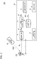
- Fig. 1 is a diagram showing an example of an exterior configuration of an electromagnetic wave phase/amplitude generation device 100.
- the electromagnetic wave phase/amplitude generation device 100 includes a radiation unit RL and a terminal device 10.
- Electromagnetic waves radiated from the radiation unit RL are radiated to an imaging object OB.
- the imaging object OB is a sample to be observed by the electromagnetic wave phase/amplitude generation device 100.
- the imaging object OB includes raw materials and materials that are an opaque and colorless transparent biological sample and a non-biological sample, and the like.
- the electromagnetic waves include at least one of the group consisting of visible rays, X rays, electron rays, ultraviolet rays, infrared rays, terahertz waves, millimeter waves, and microwaves.
- the above-described electromagnetic waves are not limited thereto and electromagnetic waves with any wavelength may be used. In this example, a case in which the electromagnetic waves are visible rays will be described.
- the terminal device 10 captures the scattered light SL scattered by the imaging object OB as a captured image.
- the terminal device 10 is a terminal including an imaging device such as a smartphone.
- the radiation unit RL includes an illumination lamp L and a scattering plate MP.
- the radiation unit RL radiates electromagnetic waves of a random radiation pattern on a spatial frequency in which a state of the electromagnetic waves to be radiated for each divided region is determined to an imaging object.
- the state of the electromagnetic waves includes states of an intensity, amplitude, and a phase of the electromagnetic waves.
- the states of the intensity and the amplitude of the electromagnetic waves are the state of the intensity of the electromagnetic waves.
- the state of the phase of the electromagnetic waves is a state of a delay or advance in the waves of the electromagnetic waves.
- the spatial frequency is a spatial frequency in a captured image captured by the terminal device 10.
- Light emitted from the illumination lamp L is incident on the scattering plate MP and is radiated from the scattering plate MP to the imaging object OB using scattered light of an intensity according to a light scattering rate differing according to each region of the scattering plate MP as the radiated light REW.
- the illumination lamp L emits light.
- the light emitted from the illumination lamp L is radiated to the imaging object OB via the scattering plate MP.
- the illumination lamp L is a light source that emits light having higher coherence than light whose phase and amplitude randomly change.
- the light source with high coherence is a light source having a correlation with the phase and the amplitude of the light emitted from the light source.
- the illumination lamp L is a laser light source, a semiconductor laser light source, or a light emitting diode (LED) light source.
- the light emitted from the illumination lamp L is radiated to the scattering plate MP
- the scattering plate MP scatters the light emitted from the illumination lamp L.
- the scattering plate MP radiates the scattered light as the radiated light REW to the imaging object OB.
- the scattering plate MP is a plate that changes an intensity of light radiated from the illumination lamp L for each region.
- the scattering plate MP is an optical element that modulates at least one of the group consisting of the intensity of electromagnetic waves, the amplitude of electromagnetic waves, and the phase of electromagnetic waves.
- the scattering plate MP is a spatial light modulator.
- the scattering plate MP has a region divided so that a degree of light scattering differs.
- the region is a region having a size corresponding to that of the imaging object OB.
- the scattering plate MP has a region divided into squares.
- the region divided so that the degree of light scattering differs has a pattern in which a light scattering rate differs.
- the scattering plate MP is a scattering plate that randomizes only the intensity of electromagnetic waves and makes the phase of electromagnetic waves constant.
- the scattering plate MP may be a scattering plate that makes the intensity of electromagnetic waves constant and randomizes only the phase of electromagnetic waves.
- the scattering plate MP may be a scattering plate which randomizes the intensity of electromagnetic waves and the phase of electromagnetic waves.
- the pattern in which the light scattering rate of the scattering plate MP is different is a pattern of a region where the light radiated to the imaging object OB is incident, but is a pattern in which a spectrum uniformly spreads on the spatial frequency.
- the pattern in which the light scattering rate of the scattering plate MP is different is a pattern of a region where the light radiated to the imaging object OB is incident, but is a pattern that does not have a peak except for an origin on the spatial frequency.
- the pattern in which the light scattering rate of the scattering plate MP is different is a white noise-like pattern on the spatial frequency.
- the white noise-like pattern is a pattern in which hardly any periodicity is observable.
- the pattern in which the light scattering rate of the scattering plate MP is different need not be a pattern having no peak at all on the spatial frequency or a pattern in which a spectrum evenly spreads on the spatial frequency.
- the terminal device 10 includes a display unit 13.
- the terminal device 10 images the scattered light SL scattered by the imaging object OB to which the radiated light REW is radiated.
- the scattered light SL scattered by the imaging object OB is information indicating a signal of the imaging object OB.
- the terminal device 10 generates information indicating at least the phase and the amplitude of the scattered light SL from the imaging object OB on the basis of the captured image of the scattered light SL and the information indicating the random radiation pattern of the scattering plate MP.
- the information indicating at least the phase and the amplitude of the scattered light SL from the imaging object OB may be referred to as complex amplitude information.
- the display unit 13 displays the intensity, the phase and the amplitude of the scattered light SL on the basis of the information indicating at least the phase and the amplitude of the scattered light SL generated by the terminal device 10. Specifically, the display unit 13 displays the complex amplitude information generated by the generation unit 12. Also, the display unit 13 displays reconstructed information about an image according to the complex amplitude information from the generation unit 12. In this example, specifically, the display unit 13 is a liquid crystal display.
- Fig. 2 is a diagram showing an example of a functional configuration of the electromagnetic wave phase/amplitude generation device 100.
- the radiation unit RL and the imaging object OB are similar to those described above.
- the terminal device 10 includes an operation detection unit 14, an imaging unit 11, an image acquisition unit 15, the generation unit 12, a storage unit 16, and the display unit 13.
- the operation detection unit 14 detects an operation from a user who operates the electromagnetic wave phase/amplitude generation device 100. More specifically, when the radiated light REW is radiated from the radiation unit RL to the imaging object OB, the operation detection unit 14 detects that the user has performed a radiation command operation. The operation detection unit 14 detecting the radiation command from the user outputs a command for radiating the radiated light REW to the radiation unit RL.
- the imaging unit 11 includes an imaging element (not shown).
- the imaging element captures the scattered light SL scattered by the imaging object OB.
- the imaging element has a plurality of pixels.
- the imaging element accumulates charges corresponding to the amplitude of the scattered light SL or the intensity of the scattered light SL in the pixels.
- the imaging unit 11 images the scattered light SL on the basis of the charges accumulated in the imaging element.
- the imaging element has pixels including y pixels in a lateral direction and x pixels in a longitudinal direction.
- a distance between the imaging object OB and the imaging element included in the imaging unit 11 is a distance z.
- the imaging unit 11 generates a captured image IP obtained by capturing the scattered light SL.
- the imaging unit 11 outputs the captured image IP generated from the scattered light SL to the image acquisition unit 15.
- the captured image IP is information indicating the intensity of the scattered light SL.
- the image acquisition unit 15 acquires the captured image IP from the imaging unit 11.
- the image acquisition unit 15 outputs the captured image IP acquired from the imaging unit 11 to the generation unit 12.
- the storage unit 16 stores pattern information RPI indicating a random radiation pattern of the scattering plate MP.
- the generation unit 12 acquires the captured image IP from the imaging unit 11.
- the generation unit 12 acquires the pattern information RPI stored in the storage unit 16.
- the generation unit 12 On the basis of the captured image IP generated by the imaging unit 11, the pattern information RPI, and the information indicating the scattered light SL, the generation unit 12 generates information indicating at least a phase and amplitude of the scattered light SL from the imaging object OB.
- the generation unit 12 generates the information indicating the phase and the amplitude by performing an arithmetic sparsity constraint operation according to sparsity of the imaging object OB.
- the information indicating the phase and the amplitude generated by the generation unit 12 is complex amplitude information of the scattered light SL.
- the generation unit 12 generates information P indicating the phase of the scattered light SL and information VA indicating the amplitude of the scattered light SL on the basis of the generated complex amplitude information.
- the generation unit 12 outputs the generated information indicating the phase and the amplitude, the information P indicating the phase of the scattered light SL, and the information VA indicating the amplitude of the scattered light SL to the display unit 13.
- the display unit 13 displays the information indicating the phase and the amplitude acquired from the generation unit 12, the information P indicating the phase of the scattered light SL, and the information VA indicating the amplitude of the scattered light SL.
- Fig. 3 is a flowchart showing an example of the operation of the electromagnetic wave phase/amplitude generation device 100.
- the radiation unit RL radiates electromagnetic waves of a random radiation pattern to the imaging object OB (step S110).
- the imaging unit 11 images the scattered light SL scattered by the imaging object OB as a captured image IP (step S120).
- the imaging unit 11 outputs the captured image IP to the generation unit 12.
- the generation unit 12 acquires the captured image IP.
- the generation unit 12 obtains pattern information RPI indicating the radiation pattern from the storage unit 16.
- the generation unit 12 generates information indicating the phase and the amplitude of the scattered light SL by performing an arithmetic sparsity constraint operation on the basis of sparsity of the imaging object OB according to the captured image IP acquired from the imaging unit 11 and the pattern information RPI acquired from the storage unit 16.
- the generation unit 12 generates information indicating the phase and the amplitude of the scattered light SL from Eq. (1) and Eq. (2).
- g 2 P z Mf 2
- Eq. (1) is an equation indicating a problem to be predicted using a forward problem, i.e., a mathematical model.
- ⁇ ⁇ arg min ⁇ ⁇ g 2 ⁇ P z Mf 2 ⁇ l 2 + ⁇ R ⁇ .
- Eq. (2) is an equation indicating an inverse problem, i.e., a problem for estimating a mathematical model from data.
- x and y included in Eq. (1) and Eq. (2) are numbers corresponding to x pixels in the longitudinal direction and y pixels in the lateral direction as the number of pixels included in the image sensor. x and y in the following equations are also similar.
- Igl2 included in Eq. (1) and Eq. (2) is the captured image IP captured by the imaging element.
- the captured image IP is information obtained by squaring an absolute value of the amplitude of the scattered light SL.
- g included in Eq. (1) and Eq. (2) is complex amplitude information indicating the phase and the amplitude of the scattered light SL.
- the complex amplitude information indicating the phase and the amplitude of the scattered light SL may be simply referred to as complex amplitude information g.
- g is a matrix shown in Eq. (3). The same also applies to g in the following mathematical expressions. [Math. 3] g ⁇ C Nx ⁇ Ny ⁇ 1
- P z included in Eq. (1) and Eq. (2) is a Toeplitz matrix of Fresnel propagation at a distance z between the imaging object OB and the imaging element. More specifically, P z is a matrix shown in Eq. (4). The same also applies to P z in the following mathematical expression. [Math. 4] P z ⁇ C Nx ⁇ Ny ⁇ Nx ⁇ Ny
- M included in Eq. (1) and Eq. (2) is a matrix indicating the pattern information RPI of the scattering plate MP.
- M is a matrix shown in Eq. (5).
- the pattern information RPI is information indicating a pattern of the scattering plate MP according to numerical values from 0 indicating that the radiated light is not scattered to 1 indicating that light is scattered with an intensity of light as it is. [Math. 5] M ⁇ C Nx ⁇ Ny ⁇ Nx ⁇ Ny
- f included in Eq. (1) and Eq. (2) is information indicating a signal of the imaging object OB. More specifically, f is a matrix shown in Eq. (6). The same also applies to f in the following mathematical expression. [Math. 6] ⁇ ⁇ C Nx ⁇ Ny ⁇ 1
- l 2 included in Eq. (2) is l 2 norm.
- l 2 in the following mathematical expression.
- R(f) included in Eq. (2) is sparsity constraint. Specifically, R(f) is a regular rule according to the sparsity of information indicating the signal of the imaging object OB. ⁇ included in Eq. (2) is a parameter for the regular rule. The same also applies to R(f) and ⁇ in the following mathematical expression.
- the generation unit 12 generates the complex amplitude information g of the scattered light SL by performing an arithmetic sparsity constraint operation according to the sparsity of the imaging object OB (step S130). Also, the generation unit 12 generates the arithmetic sparsity constraint operation according to a well-known technique. For example, the generation unit 12 performs the arithmetic sparsity constraint operation using a well-known sparse solver.
- the generation unit 12 reconstructs the intensity of the scattered light SL on the basis of the generated complex amplitude information g.
- the generation unit 12 reconstructs information indicating the intensity of the scattered light SL from the square of the absolute value of the generated complex amplitude information g.
- the generation unit 12 compares the reconstructed information indicating the intensity of the scattered light SL with the captured image obtained by imaging the imaging object OB in the imaging unit 11 (step S140).
- the process is ended (step S140; YES).
- the processing of step S130 is iterated by substituting the generated complex amplitude information g into Eq.
- the generation unit 12 may use well-known technology in a method of comparing the reconstructed information indicating the intensity of the scattered light SL with a captured image obtained by the imaging unit 11 imaging the imaging object OB. Also, it may be determined whether or not the reconstructed information indicating the intensity of the scattered light SL approximates to the captured image according to visual observation of the user using the method of comparing the reconstructed information indicating the intensity of the scattered light SL with the captured image obtained by the imaging unit 11 imaging the imaging object OB.
- the generation unit 12 generates the complex amplitude information g by solving Eq. (1) and Eq. (2).
- Eq. (1) and Eq. (2) are solved, the electromagnetic wave phase/amplitude generation device 100 may not be easily solved because the forward problem shown in Eq. (1) is a nonlinear problem.
- the generation unit 12 generates the complex amplitude information g according to alternating projection.
- z 1 included in Eq. (7) is the distance between the imaging object OB and the auxiliary plane a.
- auxiliary plane a P z 1 M ⁇
- Eq. (8) is an equation when the distance between the imaging object OB and the auxiliary plane a is z 1 . As shown in Eq. (8), the auxiliary plane a is generated by solving a linear problem.
- the auxiliary plane a is generated by an inverse Fresnel transform of g of temporary placing generated from Eq. (9) to be described below. That is, the generation unit 12 can generate the complex amplitude information g by solving a phase estimation problem.
- g ⁇ arg min g ⁇ g 2 ⁇ P z 2 a 2 ⁇ l 2
- the generation unit 12 sets a temporary value in the complex amplitude information g as an initial value.
- the temporary value of the complex amplitude information g that is the initial value may be any value.
- the generation unit 12 substitutes the auxiliary plane g in which the temporary value is set into Eq. (9).
- the generation unit 12 generates g of temporary placing according to a G-S method in Eq. (9).
- the G-S method is an iterative phase estimation method. [Math. 10]
- Eq. (10) is an equation obtained by modifying Eq. (9).
- the generation unit 12 generates g of temporary placing according to Eq. (10). Also, as shown in Eq. (10), the generation unit 12 divides the captured image IP by an element unit according to the complex amplitude information at the position of the distance z 2 and the intensity of the auxiliary plane a.
- the generation unit 12 generates g of temporary placing by multiplying a value obtained by multiplying the square root of a value divided by the element unit by the complex amplitude information and the auxiliary plane a at a position of the distance z 2 in units of elements.
- the generation unit 12 substitutes the auxiliary plane a of temporary placing generated from Eq. (10) into Eq. (11).
- the generation unit 12 generates f of temporary placing by solving Eq. (11) using a TwIST method.
- the TwIST method is a general solution of compression sensing.
- the generation unit 12 causes f of temporary placing to be propagated.
- the generation unit 12 generates the auxiliary plane a from Eq. (10) using propagated f of temporary placing as an initial value.
- the generation unit 12 substitutes a random value for the initial value of the complex amplitude information g and generates the auxiliary plane a according to the G-S method.
- the generation unit 12 substitutes the generated auxiliary plane a into Eq. (11), and generates f of temporary placing using the TwIST method.
- the generation unit 12 substitutes generated f of temporary placing into Eq. (10) and generates g of temporary placing having higher accuracy than the random value.
- the generation unit 12 iterates the above-described process until the information indicating the intensity of the scattered light SL reconstructed from g of temporary placing approximates to the captured image obtained by imaging the imaging object OB in the imaging unit 11.
- a method of solving Eq. (1) and Eq. (2) is not limited to a method according to the alternating projection of the G-S method and the TwIST method described above.
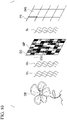
- Fig. 4 is a diagram showing an example of information VA indicating the amplitude of the scattered light SL and information P indicating the phase of the scattered light SL.
- Fig. 4(a) is an example of the information VA indicating the amplitude of the scattered light SL.
- Fig. 4(b) is an example of the information P indicating the phase of the scattered light SL.
- the information P indicating the phase is a phase obtained by rotating the original phase by 90 degrees.
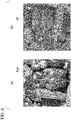
- Fig. 5 is a diagram showing an example of the scattering plate MP and the captured image IP.
- Fig. 5(a) is an example of the scattering plate MP and a scattering plate MPE obtained by enlarging a part of the scattering plate MP.
- the scattering plate MP has a random pattern on a spatial frequency. That is, when the pattern of the scattering plate MP is subjected to a Fourier transform, a pattern in which a peak on the spatial frequency is not periodically generated is given.
- Fig. 5(b) is an example of the captured image IP obtained by the imaging unit 11 imaging the scattered light SL scattered by the imaging object OB.
- Fig. 6 is a diagram showing an example of information generated from information g indicating the phase and the amplitude generated by the generation unit 12.
- Fig. 6(a) is a diagram showing an example of an intensity RVA generated from the information indicating the amplitude generated by the generation unit 12.
- the generation unit 12 When Fig. 6(a) is compared with Fig. 4(a) , it can be seen that the generation unit 12 generates amplitude information approximating to the information VA indicating the amplitude of the scattered light SL.
- Fig. 6(b) is a diagram showing an example of information RP indicating the phase generated by the generation unit 12.
- the generation unit 12 phase information approximating to the information P indicating the phase of the scattered light SL.
- the electromagnetic wave phase/amplitude generation device 100 includes the radiation unit RL, the imaging unit 11, and the generation unit 12.
- the imaging unit 11 captures the scattered light SL generated when the imaging object OB scatters the radiated light REW radiated from the radiation unit RL.
- the generation unit 12 generates the complex amplitude information g by performing an arithmetic sparsity constraint operation according to sparsity of the imaging object OB according to the captured image IP captured by the imaging unit 11, the pattern information RPI, and the information f indicating the signal of the imaging object OB.
- the electromagnetic wave phase/amplitude generation device 100 can directly detect the scattered light SL using the imaging element and can increase the signal-to-noise ratio.
- the electromagnetic wave phase/amplitude generation device 100 can directly detect the scattered light SL using the imaging element, it is possible to suppress an intensity of light emitted from the radiation unit RL as compared with a case in which the scattered light SL is not directly detected by the imaging element. That is, the electromagnetic wave phase/amplitude generation device 100 can reduce the invasiveness to the imaging object.
- the electromagnetic wave phase/amplitude generation device 100 can generate the complex amplitude information g, it is possible to obtain distribution information of a thickness of the imaging object OB and a refractive index of the electromagnetic waves. Because the electromagnetic wave phase/amplitude generation device 100 can obtain the distribution information of the thickness of the imaging object OB and the refractive index of the electromagnetic waves, it is possible to calculate quantitative information from the complex amplitude information g.
- the electromagnetic wave phase/amplitude generation device 100 can generate the complex amplitude information g on the basis of the captured image IP obtained in one imaging process and the pattern information RPI indicating the random radiation pattern, it is possible to generate the complex amplitude information g without damaging the imaging object OB vulnerable to electromagnetic waves. Also, because the electromagnetic wave phase/amplitude generation device 100 can generate the complex amplitude information g on the basis of the captured image IP obtained in one imaging process and the pattern information RPI indicating the random radiation pattern, it is possible to generate the complex amplitude information g even when the imaging object OB moves.
- the generation unit 12 iteratively generates the information g indicating at least the phase and the amplitude of the electromagnetic waves on the basis of the generated information g indicating at least the phase and the amplitude of the electromagnetic waves and the information indicating the signal of the imaging object OB.
- the generation unit 12 can make a nonlinear problem a linear problem and can generate the information g indicating at least the phase and the amplitude of the electromagnetic waves.
- the electromagnetic wave phase/amplitude generation device 100 can satisfactorily generate complex amplitude information g of the scattered light SL in all surfaces to which the radiated light REW is radiated from the radiation unit RL.
- the electromagnetic waves include at least one selected from the group consisting of visible rays, X rays, electron rays, ultraviolet rays, infrared rays, terahertz waves, millimeter waves, and microwaves. Because the electromagnetic wave phase/amplitude generation device 100 does not require a lens, it is possible to generate information indicating the phase and amplitude of electromagnetic waves such as X rays, electron rays, ultraviolet rays, infrared rays, and terahertz waves for which it is difficult to make a lens in the past. Also, because the electromagnetic wave phase/amplitude generation device 100 does not require a lens, it is possible to reduce a size of a casing of the electromagnetic wave phase/amplitude generation device 100.
- pattern information RPI is stored in the storage unit 16 for each type of scattering plate MP.
- the generation unit 12 selects the pattern information RPI to be read by an operation from the user detected by the operation detection unit 14.
- the complex amplitude information g may be calculated by another device.
- the other device is a device for a web service or the like to be operated by a server on the network.
- the generation unit 12 outputs the information necessary for generating the complex amplitude information g to the other device.
- the generation unit 12 may acquire the complex amplitude information g generated by the other device.
- Fig. 7 is a diagram showing the example of the configuration of the electromagnetic wave phase/amplitude generation device 100-1.
- the electromagnetic wave phase/amplitude generation device 100-1 according to the present embodiment is different from the above-described electromagnetic wave phase/amplitude generation device 100 in that an imaging object OB can be three-dimensionally imaged. Also, the same reference signs are given to components similar to those of the first embodiment and description thereof will be omitted.
- the electromagnetic wave phase/amplitude generation device 100-1 generates information indicating a phase and the amplitude of scattered light SL by performing an arithmetic sparsity constraint operation according to the sparsity of the imaging object OB on the basis of states of wavefronts of the scattered light SL at a plurality of distances.
- the wavefronts of the scattered light SL at the plurality of distances refer to a plurality of wavefronts separated from each other in a traveling direction of the scattered light SL among wavefronts of the scattered light SL.
- the wavefronts of the scattered light SL at the plurality of distances are wavefronts having distances different from each other from the imaging unit 11 at a certain moment.
- a storage unit 16 stores pattern information RPI.
- the pattern information RPI of the present embodiment includes distance-specific wavefront pattern information indicating the states of the wavefronts of the scattered light SL at the plurality of distances.
- the storage unit 16 stores the pattern information RPI including the distance-specific wavefront pattern information.
- a generation unit 12 generates the information indicating the phase and the amplitude of the scattered light SL by performing an arithmetic sparsity constraint operation according to the sparsity of the imaging object OB on the basis of the captured image IP acquired from the imaging unit 11 and the pattern information RPI acquired from the storage unit 16.
- the generation unit 12 of the present embodiment performs an arithmetic sparsity constraint operation according to the sparsity of the imaging object OB for each wavefront of the scattered light SL on the basis of distance-specific wavefront pattern information included in the pattern information RPI.
- information about each tomographic plane of the imaging object OB is included in each wavefront of the scattered light SL imaged by the imaging unit 11.
- the generation unit 12 generates information indicating a phase and amplitude of each tomographic plane of the imaging object OB by performing an arithmetic sparsity constraint operation on each wavefront of the scattered light SL.
- the electromagnetic wave phase/amplitude generation device 100-1 can generate the information indicating the phase and amplitude of each tomographic plane of the imaging object OB generated by the generation unit 12, i.e., information indicating a three-dimensional structure of the imaging object OB.
- Fig. 8 is an example of a tomographic amplitude image of the imaging object OB generated by the generation unit 12.
- Fig. 9 is an example of a tomographic phase image of the imaging object OB generated by the generation unit 12.
- Figs. 8 and 9 show an example of a case when the imaging object OB is Volvox.
- the electromagnetic wave phase/amplitude generation device 100-1 it is possible to generate a tomographic image in which a position of the imaging unit 11 in an optical axis AX direction is variously changed.
- the electromagnetic wave phase/amplitude generation device 100-1 it is possible to obtain an image indicating the three-dimensional structure of the imaging object OB by reconstructing the tomographic image.
- the electromagnetic wave phase/amplitude generation device 100-2 according to the present embodiment is different from the electromagnetic wave phase/amplitude generation device 100 and the electromagnetic wave phase/amplitude generation device 100-1 in that it is possible to obtain information indicating a phase and amplitude of high resolution even when the resolution of an imaging unit 11 is relatively low. Also, the same reference signs are given to components similar to those in each of the above-described embodiments and the description thereof will be omitted.
- Fig. 10 is a diagram showing an example of the configuration of the electromagnetic wave phase/amplitude generation device 100-2.
- the example of Fig. 10 is presented for the purpose of explanation. The scope of protection sought is defined by the appended claims.
- Fig. 11 is a diagram showing another example of the configuration of the electromagnetic wave phase/amplitude generation device 100-2.
- the resolution of the imaging unit 11 is lower than the resolution of an arithmetic sparsity constraint operation of a generation unit 12, this means that the number of pixels of an imaging element of the imaging unit 11 is relatively small.
- the resolution of the imaging unit 11 is low, this means that the number of pixels of the imaging element of the imaging unit 11 is smaller than the number of pixels for which a spatial frequency of a pattern of a scattering plate MP can be resolved.
- the low resolution of the imaging unit 11 means that the number of pixels of the imaging element of the imaging unit 11 is smaller than the number of scattering sections of the scattering plate MP.
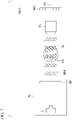
- Fig. 10 shows an example of a configuration of coded aperture type diffraction imaging.
- object light OL emitted from an imaging object OB is incident on the scattering plate MP.
- the scattered light SL according to the object light OL is emitted from the scattering plate MP and the emitted scattered light SL is incident on the imaging unit 11. That is, in the case of the configuration of the present example, the scattering plate MP is disposed between the imaging object OB and the imaging unit 11.
- a ratio of the number of pixels PX of the imaging element of the imaging unit 11 to the number of scattering sections SC of the scattering plate MP is 1:4 is shown.
- the number of pixels PX of the imaging element of the imaging unit 11 is smaller than the number of scattering sections SC of the scattering plate MP.
- radiated light REW is emitted from the scattering plate MP and the emitted radiated light REW is radiated to the imaging object OB.
- the radiated light REW is radiated to the imaging object OB
- the scattered light SL corresponding to the radiated light REW is emitted from the imaging object OB and the emitted scattered light SL is incident on the imaging unit 11. That is, in the case of the configuration of the present example, the imaging object OB is disposed between the scattering plate MP and the imaging unit 11.
- a ratio between the number of pixels PX of the imaging element of the imaging unit 11 and the number of scattering sections SC of the scattering plate MP is 1:4. That is, also in the example of Fig. 11 , the number of pixels PX of the imaging element of the imaging unit 11 is smaller than the number of scattering sections SC of the scattering plate MP.
- the ratio between the number of pixels PX of the imaging element of the imaging unit 11 and the number of scattering sections SC of the scattering plate MP may be made variable by so-called binning.
- the binning is to perform an imaging operation by grouping several pixels PX among the pixels PX of the imaging element and designating the grouped pixels PX as one pixel. As an example, if 2 ⁇ 2 binning is performed on the pixels PX of the imaging element of the imaging unit 11, the number of pixels after binning becomes 1/4 of that before binning.
- the imaging unit 11 of the present embodiment may be configured so that binning according to a type or magnitude of the imaging object OB or according to desired resolution or processing speed is possible.
- the generation unit 12 generates information indicating the phase and the amplitude of the scattered light SL by performing the arithmetic sparsity constraint operation according to arithmetic operations shown in Eq. (1) and Eq. (2), i.e., on the basis of the pattern information RPI of the scattering plate MP.
- the number of pixels of the imaging element of the imaging unit 11 is smaller than the number of scattering sections of the scattering plate MP.
- 2 included in Eq. (1) and Eq. (2) is not the same as a magnitude of the matrix of M included in in Eq. (1) and Eq. (2).
- the magnitude of the matrix used herein is, for example, the number of rows and the number of columns of the matrix. In this manner, when the magnitude of the matrix of
- an arithmetic operation of generating the phase and amplitude of the scattered light SL is performed on the basis of a correspondence relationship between the two matrices.
- the arithmetic operation of generating the phase and the amplitude of the scattered light SL is performed by making the magnitudes of the two matrices the same.
- a procedure of making the magnitudes of the two matrices the same includes the following two procedures.
- phase and the amplitude of the scattered light SL are generated by interpolating (for example, linearly interpolating) the captured image IP captured by the imaging unit 11.
- the generation unit 12 of the present embodiment adopts (Procedure 2).
- the generation unit 12 of the present embodiment performs the arithmetic operation without interpolating the element of
- the storage unit 16 of the present embodiment a correspondence relationship between the elements of the matrix of
- the generation unit 12 generates the phase and the amplitude of the scattered light SL by associating pixel values of the captured image IP with the elements of the matrix of M on the basis of the correspondence relationship stored in the storage unit 16.
- 2 and the elements of the matrix of M is an example of the correspondence relationship between the resolution of the imaging unit 11 and the resolution of the arithmetic sparsity constraint operation of the generation unit 12.
- Examples of experiment results for generating an amplitude image and a phase image in the electromagnetic wave phase/amplitude generation device 100-2 according to the present embodiment will be described with reference to Figs. 12 to 23 .
- First, an example of an experiment result for an amplitude image will be described with reference to Figs. 12 to 17 .
- an example of an experiment result for a phase image will be described with reference to Figs. 18 to 23 .
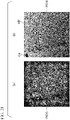
- Fig. 12 is a diagram showing an example of a comparison of the number of pixels of captured images IP.
- Fig. 12(A) shows an example of a captured image IP (an image PIC1) from the imaging unit 11 when the number of pixels of the imaging element of the imaging unit 11 is the same as the number of scattering sections of the scattering plate MP.
- Fig. 12(B) shows an example of a captured image IP (an image PIC2) from the imaging unit 11 when the number of pixels of the imaging element of the imaging unit 11 is smaller than the number of scattering sections of the scattering plate MP.
- the imaging object OB is a wire (a thin metal wire).
- a position of the wire which is the imaging object OB periodically moves. Therefore, in this example, the positions of the wire imaged in the captured image IP are different from each other according to an imaging timing.
- the distance between the pixels of the captured image IP when the number of pixels of the imaging element is smaller than the number of scattering sections of the scattering plate MP ( Fig. 12(B) ) is larger than that when the number of pixels of the imaging element is the same as the number of scattering sections of the scattering plate MP ( Fig. 12(A) ). That is, when the number of pixels of the imaging element is smaller than the number of scattering sections of the scattering plate MP, the resolution of the captured image IP is low.
- Fig. 13 is a diagram showing an example of an amplitude image and a phase image of the scattered light SL when the number of pixels of the imaging element is the same as the number of scattering sections of the scattering plate MP.
- Fig. 13(A) is an example of an amplitude image (an image PIC3) of the scattered light SL when the number of pixels of the imaging element is the same as the number of scattering sections of the scattering plate MP.
- Fig. 13(B) is an example of a phase image (an image PIC4) of the scattered light SL when the number of pixels of the imaging element is the same as the number of scattering sections of the scattering plate MP.
- Fig. 13(B) shows the amplitude image and the phase image of the scattered light SL when the number of pixels of the imaging element of the imaging unit 11 is relatively large, i.e., when the resolution is high.
- Fig. 14 is a diagram showing an example of an amplitude image and a phase image of the scattered light SL from the generation unit 12 when the number of pixels of the imaging element is smaller than the number of scattering sections of the scattering plate MP. That is, Fig. 14 shows the amplitude image (an image PIC5) and the phase image (an image PIC6) of the scattered light SL when the number of pixels of the imaging element of the imaging unit 11 is relatively small, i.e., when the resolution is low.
- the generation unit 12 generates an amplitude image and a phase image of the scattered light SL according to the above-described (Procedure 2).
- the generation unit 12 generates the phase and the amplitude of the scattered light SL by associating the pixel value of the captured image IP with each element of the matrix of M on the basis of a correspondence relationship between each element of the matrix of
- Fig. 14(A) is an example of an amplitude image of the scattered light SL when the element of
- Fig. 14(B) is an example of a phase image of the scattered light SL when the element of
- Fig. 15 is a diagram showing an example of an amplitude image (an image PIC7) and a phase image (an image PIC8) of the scattered light SL according to the conventional technique.
- both the amplitude image and the phase image have lower resolutions than those in the case of the generation unit 12 of the present embodiment (the case of Fig. 14 ).
- the number of pixels of the imaging element of the imaging unit 11 is smaller than the number of scattering sections of the scattering plate MP. That is, in the case of the present embodiment, the resolution of the imaging unit 11 is low with respect to the spatial frequency of the scattering plate MP. Thus, if the generation unit 12 generates an amplitude image or a phase image using the captured image IP captured by the imaging unit 11 for only one frame, the resolution of the generated image is lowered.
- the generation unit 12 of the present embodiment iteratively generates the amplitude image and the phase image using captured images IP of a plurality of frames.
- the captured images IP of the plurality of frames the imaging object OB is imaged.
- the imaging object OB imaged in the plurality of captured images IP differs according to each frame. That is, the plurality of captured images IP include different information of the imaging object OB.
- the generation unit 12 can acquire more information than the information obtained from the captured image IP of one frame with respect to the imaging object OB by iteratively acquiring the information of the imaging object OB included in the captured image IP for each frame. Thereby, the generation unit 12 can generate an amplitude image and a phase image with resolutions exceeding the resolution of the imaging unit 11.
- the imaging element outputs a signal indicating a pixel value of the captured image for each pixel. If an output time of the signal indicating the pixel value is constant for each pixel, an output time of signals from all pixels of the imaging element when the number of pixels of the imaging element is small is shorter than that when the number of pixels is large . That is, a speed of an imaging operation when the number of pixels is small can be made higher than that when the number of pixels is large.
- Fig. 16 is a diagram showing an example of an amplitude image and a phase image generated in time series.
- Fig. 16(A) shows an example of an amplitude image and a phase image generated in the condition shown in Fig. 12(A) , i.e., when the number of pixels of the imaging element of the imaging unit 11 is the same as the number of scattering sections of the scattering plate MP.
- Fig. 16(B) and Fig. 16(C) show an example of an amplitude image and a phase image generated in the condition shown in Fig. 12(B) , i.e., when the number of pixels of the imaging element of the imaging unit 11 is smaller than the number of scattering sections of the scattering plate MP.
- Fig. 16(A) shows an example of an amplitude image and a phase image generated in the condition shown in Fig. 12(A) , i.e., when the number of pixels of the imaging element of the imaging unit 11 is the same as the number of scattering sections of the
- FIG. 16(B) shows an example of an amplitude image and a phase image generated according to the above-described (Procedure 1), i.e., the conventional procedure.
- Fig. 16(C) shows an example of an amplitude image and a phase image generated according to the above-described (Procedure 2), i.e., a procedure adopted by the generation unit 12 of the present embodiment.
- the resolution of the imaging unit 11 of the present embodiment is lower than the resolution of the arithmetic sparsity constraint operation of the generation unit 12. That is, the number of pixels of the imaging unit 11 of the present embodiment is smaller than the number of scattering sections of the scattering plate MP. In other words, the number of pixels of the imaging element of the imaging unit 11 is smaller than that when the number of pixels of the imaging element is the same as the number of scattering sections of the scattering plate MP.
- the imaging unit 11 of the present embodiment has a higher imaging operation speed ( Fig. 16(C) ) than when the number of pixels of the imaging element is the same as the number of scattering sections of the scattering plate MP ( Fig. 16(A) ).
- the resolution of the imaging unit 11 of the present embodiment generates an amplitude image and a phase image according to the above-described (Procedure 2).
- (Procedure 1) that is the conventional technique
- information that is not included in the captured image IP captured by the imaging unit 11 is generated by interpolation as described above.
- the information that is not included in the captured image IP corresponds to a noise component in an arithmetic operation according to Eq. (1) and Eq. (2) described above. Therefore, resolutions of the amplitude image and the phase image ( Fig. 16(B) ) generated according to (Procedure 1) that is the conventional technique are lower than those of the amplitude image and the phase image ( Fig. 16(C) ) generated according to (Procedure 2). That is, the generation unit 12 of the present embodiment can generate an amplitude image and a phase image having higher resolutions than those of the conventional technique.
- Fig. 17 is a diagram showing an example of a result of comparing resolutions of amplitude images.
- a relationship between a coordinate of the imaging object OB indicated by the amplitude image and amplitude (intensity) is shown.
- Waveforms when the imaging element has higher resolution than the imaging element of the imaging unit 11 of the present embodiment are shown as waveforms W1A and W1B.
- the waveform W1A thereof indicates the resolution of the amplitude image when the imaging object OB is stopped in Fig. 16(A) .
- the waveform W1A is a reference example of the resolution of the amplitude image.
- the waveform W1B shows the resolution of the amplitude image when the imaging object OB moves in Fig. 16(A) .
- the imaging operation speed is slow, so that the image is blurred.
- This waveform W1B shows that the coordinate spread is greater than that of the above-described waveform W1A and that the resolution is lower than that of the reference example.
- the waveform when the amplitude image is generated according to the above-described (Procedure 2), i.e., a technique adopted by the generation unit 12 of the present embodiment, (i.e., in the case of Fig. 16(C) ) is shown as a waveform W1C.
- the waveform W1C indicates the resolution of the amplitude image when the imaging object OB moves in Fig. 16(C) .
- This waveform W1C shows that the coordinate spread is less than that of the above-described waveform W1B, that the resolution is improved, and that the resolution equivalent to that of the reference example is obtained even when the imaging object OB moves.
- Fig. 18 is a diagram showing another example of a comparison of the number of pixels of captured images IP.
- Fig. 18(A) shows an example of a captured image IP (an image PIC9) from the imaging unit 11 when the number of pixels of the imaging element of the imaging unit 11 is the same as the number of scattering sections of the scattering plate MP.
- Fig. 18(B) shows an example of a captured image IP (an image PIC10) from the imaging unit 11 when the number of pixels of the imaging element of the imaging unit 11 is smaller than the number of scattering sections of the scattering plate MP.
- a thin glass for example, a cover glass CG
- an angle of view of the captured image IP when the number of pixels of the imaging element is smaller than the number of scattering sections of the scattering plate MP ( Fig. 18(B) ) is narrower than that when the number of pixels of the imaging element is the same as the number of scattering sections of the scattering plate MP ( Fig. 18(A) ). That is, when the number of pixels of the imaging element is smaller than the number of scattering sections of the scattering plate MP, the resolution of the captured image IP is low.
- Fig. 19 is a diagram showing an example of an amplitude image and a phase image of the scattered light SL when the number of pixels of the imaging element is the same as the number of scattering sections of the scattering plate MP.
- Fig. 19(A) is an example of an amplitude image (an image PIC11) of the scattered light SL when the number of pixels of the imaging element is the same as the number of scattering sections of the scattering plate MP.
- Fig. 19(B) is an example of a phase image (an image PIC12) of the scattered light SL when the number of pixels of the imaging element is the same as the number of scattering sections of the scattering plate MP.
- Fig. 19(B) shows the amplitude image and the phase image of the scattered light SL when the number of pixels of the imaging element of the imaging unit 11 is relatively large, i.e., when the resolution is high.
- Fig. 20 is a diagram showing an example of an amplitude image and a phase image of the scattered light SL from the generation unit 12 when the number of pixels of the imaging element is smaller than the number of scattering divisions of the scattering plate MP. That is, Fig. 20 shows an amplitude image (an image PIC13) and a phase image (an image PIC14) of the scattered light SL when the number of pixels of the imaging element of the imaging unit 11 is relative small, i.e., when the resolution is low.
- the generation unit 12 generates an amplitude image and a phase image of the scattered light SL according to the above-described (Procedure 2).
- Fig. 20(A) is an example of the amplitude image of the scattered light SL when the element of
- Fig. 20(B) is an example of a phase image of the scattered light SL when the element of
- Fig. 21 is a diagram showing an example of an amplitude image (an image PIC15) and a phase image (an image PIC16) of the scattered light SL according to the conventional technique.
- both the amplitude image and the phase image have lower resolutions than those in the case of the generation unit 12 of the present embodiment (the case of Fig. 20 ).
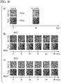
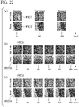
- Fig. 22 is a diagram showing another example of an amplitude image and a phase image generated in time series.
- Fig. 22(A) shows an example of an amplitude image and a phase image generated in the condition shown in Fig. 18(A) , i.e., when the number of pixels of the imaging element of the imaging unit 11 is the same as the number of scattering sections of the scattering plate MP.
- Fig. 22(B) and Fig. 22(C) all show an example of an amplitude image and a phase image generated in the condition shown in Fig. 18(B) , i.e., when the number of pixels of the imaging element of the imaging unit 11 is smaller than the number of scattering sections of the scattering plate MP.
- Fig. 22(A) shows an example of an amplitude image and a phase image generated in the condition shown in Fig. 18(A) , i.e., when the number of pixels of the imaging element of the imaging unit 11 is smaller than the number of scattering sections of the
- FIG. 22(B) shows an example of an amplitude image and a phase image generated according to the above-described (Procedure 1), i.e., the conventional procedure.
- Fig. 22(C) shows an example of an amplitude image and a phase image generated according to the above-described (Procedure 2), i.e., a procedure adopted by the generation unit 12 of the present embodiment.
- the resolution of the imaging unit 11 of the present embodiment is lower than the resolution of the arithmetic sparsity constraint operation of the generation unit 12. That is, the number of pixels of the imaging unit 11 of the present embodiment is smaller than the number of scattering sections of the scattering plate MP. In other words, the number of pixels of the imaging element of the imaging unit 11 is smaller than that when the number of pixels of the imaging element is the same as the number of scattering sections of the scattering plate MP.
- the imaging unit 11 of the present embodiment has a higher imaging operation speed ( Fig. 22(C) ) than when the number of pixels of the imaging element is the same as the number of scattering sections of the scattering plate MP ( Fig. 22(A) ).
- Resolutions of the amplitude image and the phase image ( Fig. 22(B) ) generated according to (Procedure 1) that is the conventional technique are lower than resolutions of the amplitude image and the phase image ( Fig. 22(C) ) generated according to (Procedure 2). That is, the generation unit 12 of the present embodiment can generate an amplitude image and a phase image having higher resolutions than those of the conventional technique.
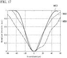
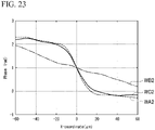
- Fig. 23 is a diagram showing an example of a result of comparing resolutions of phase images.
- a relationship between a coordinate of the imaging object OB indicated by a phase image and a phase is shown.
- Waveforms when the imaging element has higher resolution than the imaging element of the imaging unit 11 of the present embodiment are shown as waveforms W2A and W2B.
- the waveform W2A thereof indicates the resolution of the phase image when the imaging object OB is stopped in Fig. 22(A) .
- the waveform W2A is a reference example of the resolution of the phase image.
- the waveform W2B shows the resolution of the phase image when the imaging object OB moves in Fig. 22(A) .
- the imaging operation speed is slow, so that the image is blurred.
- This waveform W2B shows that a change in the phase in a reference coordinate (0 (zero) in this example) is not clearer than the waveform W2A and that the resolution is lower than that of the reference example.
- the waveform when the phase image is generated according to the above-described (Procedure 2), i.e., a technique adopted by the generation unit 12 of the present embodiment, (i.e., in the case of Fig. 22(C) ) is shown as a waveform W2C.
- the waveform W2C indicates the resolution of the phase image when the imaging object OB moves in Fig. 22(C) .
- This waveform W2C shows that the change in the phase is clearer than that of the above-described waveform W2B, i.e., that the resolution is improved, and that the resolution equivalent to that of the reference example is obtained even when the imaging object OB moves.
- the electromagnetic wave phase/amplitude generation device 100-2 of the present embodiment can improve resolutions of an amplitude image and a phase image by increasing a speed of an operation according to a decrease in the number of pixels of the imaging unit 11 and generating the amplitude image and the phase image without interpolating the pixel value. That is, the electromagnetic wave phase/amplitude generation device 100-2 of the present embodiment can achieve both a high-speed operation and improved resolutions of the generated amplitude image and phase image.
- the above-described electromagnetic wave phase/amplitude generation device 100 internally includes a computer. Processes of various types of processing of the above-described device are stored in a computer-readable recording medium in the form of the program and various types of processing described above are performed by the computer reading and executing this program.
- the computer-readable recording medium refers to a magnetic disk, a magneto-optical disc, a CD-ROM, a DVD-ROM, a semiconductor memory, or the like.
- a computer program may be delivered to a computer through a communication circuit and the computer receiving the delivered computer program may execute the program.
- the above-described program may be a program for implementing some of the above-described functions. Further, the above-described program may be a program capable of implementing the above-described functions in combination with a program already recorded on the computer system, i.e., a so-called differential file (differential program).
Landscapes
- Physics & Mathematics (AREA)
- General Physics & Mathematics (AREA)
- Spectroscopy & Molecular Physics (AREA)
- Health & Medical Sciences (AREA)
- General Health & Medical Sciences (AREA)
- Biochemistry (AREA)
- Pathology (AREA)
- Immunology (AREA)
- Life Sciences & Earth Sciences (AREA)
- Chemical & Material Sciences (AREA)
- Analytical Chemistry (AREA)
- Engineering & Computer Science (AREA)
- Theoretical Computer Science (AREA)
- Signal Processing (AREA)
- Computing Systems (AREA)
- Electromagnetism (AREA)
- Toxicology (AREA)
- Multimedia (AREA)
- Investigating Or Analysing Materials By Optical Means (AREA)
Description
- The present invention relates to an electromagnetic wave phase/amplitude generation device, an electromagnetic wave phase/amplitude generation method, and an electromagnetic wave phase/amplitude generation program.
- Priority is claimed on
Japanese Patent Application No. 2016-159312, filed August 15, 2016 - Conventionally, technology for radiating electromagnetic waves to an imaging object, imaging scattered electromagnetic waves generated when the imaging object scatters the radiated electromagnetic waves via a scattering plate having a random pattern in which a magnitude for attenuating the electromagnetic waves differs according to each region, and generating complex amplitude indicating a phase and amplitude of the electromagnetic waves scattered by the imaging object from a captured image and the random pattern is known (for example, Non-Patent Document 1).
- Imaging With Nature: A Universal Analog Compressive Imager Using a Multiply Scattering Medium by Antoine Liutkus et al (2013-09-02, XP055194020) constitutes background art.
- [Non-Patent Document 1]
Single-shot phase imaging with a coded aperture (OPTICS LETTERS/Vol. 39, No. 22/November 15, 2014) - In the conventional technology, it is possible to generate complex amplitude indicating a phase and amplitude of electromagnetic waves scattered by an imaging object in one imaging process. However, a scattering plate weakens the electromagnetic waves scattered from the imaging object, a signal-to-noise ratio decreases, and noise increases. Also, if a state of the electromagnetic waves radiated to the imaging object is strengthened by an amount corresponding to the electromagnetic waves weakened by the scattering plate, there is a problem in that invasiveness with respect to the imaging object becomes high and the imaging object is adversely affected due to this high invasiveness.
- An objective of the present invention is to provide an electromagnetic wave phase/amplitude generation device, an electromagnetic wave phase/amplitude generation method, and an electromagnetic wave phase/amplitude generation program having a high signal-to-noise ratio and low invasiveness to an imaging object.
- According to an aspect of the present invention, there is provided an electromagnetic wave phase/amplitude generation device as recited in appended
indepedent claim 1. - Also, according to an aspect of the present invention, there is provided an electromagnetic wave phase/amplitude generation method as recited in appended independent claim 6, and a computer-readable medium storing instructions which, when executed by a computer, cause the computer to execute the method of claim 6, as recited in appended claim 7. Other aspects of the invention are recited in the appended dependent claims.
- According to the present invention, it is possible to provide an electromagnetic wave phase/amplitude generation device, an electromagnetic wave phase/amplitude generation method, and an electromagnetic wave phase/amplitude generation program having a high signal-to-noise ratio and low invasiveness to an imaging object.
-
-
Fig. 1 is a diagram showing an example of an exterior configuration of an electromagnetic wave phase/amplitude generation device. -
Fig. 2 is a diagram showing an example of a functional configuration of the electromagnetic wave phase/amplitude generation device. -
Fig. 3 is a flowchart showing an example of an operation of the electromagnetic wave phase/amplitude generation device. -
Fig. 4 is a diagram showing an example of information indicating amplitude of scattered light and information indicating a phase of scattered light. -
Fig. 5 is a diagram showing an example of a scattering plate and a captured image. -
Fig. 6 is a diagram showing an example of information generated by a generation unit from complex amplitude information. -
Fig. 7 is a diagram showing an example of a configuration of the electromagnetic wave phase/amplitude generation device. -
Fig. 8 is an example of a tomographic amplitude image of an imaging object generated by the generation unit. -
Fig. 9 is an example of a tomographic phase image of an imaging object generated by the generation unit. -
Fig. 10 is a diagram showing an example of a configuration of the electromagnetic wave phase/amplitude generation device -
Fig. 11 is a diagram showing another example of a configuration of the electromagnetic wave phase/amplitude generation device. -
Fig. 12 is a diagram showing an example of a comparison of the number of pixels of captured images. -
Fig. 13 is a diagram showing an example of an amplitude image and a phase image of scattered light when the number of pixels of the imaging element is the same as the number of scattering sections of the scattering plate. -
Fig. 14 is a diagram showing an example of an amplitude image and a phase image of scattered light from the generation unit when the number of pixels of the imaging element is smaller than the number of scattering sections of the scattering plate. -
Fig. 15 is a diagram showing an example of an amplitude image and a phase image of scattered light according to a conventional technique. -
Fig. 16 is a diagram showing an example of an amplitude image and a phase image generated in time series. -
Fig. 17 is a diagram showing an example of a result of comparing resolutions of amplitude images. -
Fig. 18 is a diagram showing another example of a comparison of the number of pixels of captured images. -
Fig. 19 is a diagram showing an example of an amplitude image and a phase image of scattered light when the number of pixels of the imaging element is the same as the number of scattering sections of the scattering plate. -
Fig. 20 is a diagram showing an example of an amplitude image and a phase image of scattered light from the generation unit when the number of pixels of the imaging element is smaller than the number of scattering sections of the scattering plate. -
Fig. 21 is a diagram showing an example of an amplitude image and a phase image of scattered light according to a conventional technique. -
Fig. 22 is a diagram showing another example of an amplitude image and a phase image generated in time series. -
Fig. 23 is a diagram showing an example of a result of comparing resolutions of phase images. - Hereinafter, an embodiment of an electromagnetic wave phase/amplitude generation device will be described with reference to the drawings.
-
Fig. 1 is a diagram showing an example of an exterior configuration of an electromagnetic wave phase/amplitude generation device 100. - The electromagnetic wave phase/
amplitude generation device 100 includes a radiation unit RL and aterminal device 10. - Electromagnetic waves radiated from the radiation unit RL are radiated to an imaging object OB. The imaging object OB is a sample to be observed by the electromagnetic wave phase/
amplitude generation device 100. Specifically, the imaging object OB includes raw materials and materials that are an opaque and colorless transparent biological sample and a non-biological sample, and the like. Here, the electromagnetic waves include at least one of the group consisting of visible rays, X rays, electron rays, ultraviolet rays, infrared rays, terahertz waves, millimeter waves, and microwaves. Also, the above-described electromagnetic waves are not limited thereto and electromagnetic waves with any wavelength may be used. In this example, a case in which the electromagnetic waves are visible rays will be described. In the following description, visible rays may be simply described as light. Also, in the following description, light radiated from the radiation unit RL is also referred to as radiated light REW. Theterminal device 10 captures the scattered light SL scattered by the imaging object OB as a captured image. In this example, theterminal device 10 is a terminal including an imaging device such as a smartphone. - The radiation unit RL includes an illumination lamp L and a scattering plate MP. The radiation unit RL radiates electromagnetic waves of a random radiation pattern on a spatial frequency in which a state of the electromagnetic waves to be radiated for each divided region is determined to an imaging object. The state of the electromagnetic waves includes states of an intensity, amplitude, and a phase of the electromagnetic waves. The states of the intensity and the amplitude of the electromagnetic waves are the state of the intensity of the electromagnetic waves. The state of the phase of the electromagnetic waves is a state of a delay or advance in the waves of the electromagnetic waves.
- The spatial frequency is a spatial frequency in a captured image captured by the
terminal device 10. Light emitted from the illumination lamp L is incident on the scattering plate MP and is radiated from the scattering plate MP to the imaging object OB using scattered light of an intensity according to a light scattering rate differing according to each region of the scattering plate MP as the radiated light REW. - Specifically, the illumination lamp L emits light. The light emitted from the illumination lamp L is radiated to the imaging object OB via the scattering plate MP. The illumination lamp L is a light source that emits light having higher coherence than light whose phase and amplitude randomly change. In other words, the light source with high coherence is a light source having a correlation with the phase and the amplitude of the light emitted from the light source. More specifically, the illumination lamp L is a laser light source, a semiconductor laser light source, or a light emitting diode (LED) light source.
- The light emitted from the illumination lamp L is radiated to the scattering plate MP The scattering plate MP scatters the light emitted from the illumination lamp L. The scattering plate MP radiates the scattered light as the radiated light REW to the imaging object OB. The scattering plate MP is a plate that changes an intensity of light radiated from the illumination lamp L for each region. The scattering plate MP is an optical element that modulates at least one of the group consisting of the intensity of electromagnetic waves, the amplitude of electromagnetic waves, and the phase of electromagnetic waves. The scattering plate MP is a spatial light modulator.
- The scattering plate MP has a region divided so that a degree of light scattering differs. Here, the region is a region having a size corresponding to that of the imaging object OB. In this example, the scattering plate MP has a region divided into squares. Also, the region divided so that the degree of light scattering differs has a pattern in which a light scattering rate differs. Specifically, the scattering plate MP is a scattering plate that randomizes only the intensity of electromagnetic waves and makes the phase of electromagnetic waves constant. Also, the scattering plate MP may be a scattering plate that makes the intensity of electromagnetic waves constant and randomizes only the phase of electromagnetic waves. The scattering plate MP may be a scattering plate which randomizes the intensity of electromagnetic waves and the phase of electromagnetic waves.
- Here, in the example of the present embodiment, the pattern in which the light scattering rate of the scattering plate MP is different is a pattern of a region where the light radiated to the imaging object OB is incident, but is a pattern in which a spectrum uniformly spreads on the spatial frequency. In other words, the pattern in which the light scattering rate of the scattering plate MP is different is a pattern of a region where the light radiated to the imaging object OB is incident, but is a pattern that does not have a peak except for an origin on the spatial frequency.
- Specifically, the pattern in which the light scattering rate of the scattering plate MP is different is a white noise-like pattern on the spatial frequency. The white noise-like pattern is a pattern in which hardly any periodicity is observable. In other words, the pattern in which the light scattering rate of the scattering plate MP is different need not be a pattern having no peak at all on the spatial frequency or a pattern in which a spectrum evenly spreads on the spatial frequency.
- The
terminal device 10 includes adisplay unit 13. Theterminal device 10 images the scattered light SL scattered by the imaging object OB to which the radiated light REW is radiated. The scattered light SL scattered by the imaging object OB is information indicating a signal of the imaging object OB. Theterminal device 10 generates information indicating at least the phase and the amplitude of the scattered light SL from the imaging object OB on the basis of the captured image of the scattered light SL and the information indicating the random radiation pattern of the scattering plate MP. In the following description, the information indicating at least the phase and the amplitude of the scattered light SL from the imaging object OB may be referred to as complex amplitude information. - The
display unit 13 displays the intensity, the phase and the amplitude of the scattered light SL on the basis of the information indicating at least the phase and the amplitude of the scattered light SL generated by theterminal device 10. Specifically, thedisplay unit 13 displays the complex amplitude information generated by thegeneration unit 12. Also, thedisplay unit 13 displays reconstructed information about an image according to the complex amplitude information from thegeneration unit 12. In this example, specifically, thedisplay unit 13 is a liquid crystal display. - Next, an example of the configuration of the electromagnetic wave phase/
amplitude generation device 100 according to the present embodiment will be described with reference toFig. 2 . -
Fig. 2 is a diagram showing an example of a functional configuration of the electromagnetic wave phase/amplitude generation device 100. The radiation unit RL and the imaging object OB are similar to those described above. - The
terminal device 10 includes anoperation detection unit 14, animaging unit 11, animage acquisition unit 15, thegeneration unit 12, astorage unit 16, and thedisplay unit 13. - The
operation detection unit 14 detects an operation from a user who operates the electromagnetic wave phase/amplitude generation device 100. More specifically, when the radiated light REW is radiated from the radiation unit RL to the imaging object OB, theoperation detection unit 14 detects that the user has performed a radiation command operation. Theoperation detection unit 14 detecting the radiation command from the user outputs a command for radiating the radiated light REW to the radiation unit RL. - The
imaging unit 11 includes an imaging element (not shown). The imaging element captures the scattered light SL scattered by the imaging object OB. Specifically, the imaging element has a plurality of pixels. The imaging element accumulates charges corresponding to the amplitude of the scattered light SL or the intensity of the scattered light SL in the pixels. Theimaging unit 11 images the scattered light SL on the basis of the charges accumulated in the imaging element. In the following description, the imaging element has pixels including y pixels in a lateral direction and x pixels in a longitudinal direction. A distance between the imaging object OB and the imaging element included in theimaging unit 11 is a distance z. Theimaging unit 11 generates a captured image IP obtained by capturing the scattered light SL. Theimaging unit 11 outputs the captured image IP generated from the scattered light SL to theimage acquisition unit 15. In the following description, the captured image IP is information indicating the intensity of the scattered light SL. - The
image acquisition unit 15 acquires the captured image IP from theimaging unit 11. Theimage acquisition unit 15 outputs the captured image IP acquired from theimaging unit 11 to thegeneration unit 12. - The
storage unit 16 stores pattern information RPI indicating a random radiation pattern of the scattering plate MP. - The
generation unit 12 acquires the captured image IP from theimaging unit 11. Thegeneration unit 12 acquires the pattern information RPI stored in thestorage unit 16. - On the basis of the captured image IP generated by the
imaging unit 11, the pattern information RPI, and the information indicating the scattered light SL, thegeneration unit 12 generates information indicating at least a phase and amplitude of the scattered light SL from the imaging object OB. Thegeneration unit 12 generates the information indicating the phase and the amplitude by performing an arithmetic sparsity constraint operation according to sparsity of the imaging object OB. The information indicating the phase and the amplitude generated by thegeneration unit 12 is complex amplitude information of the scattered light SL. Thegeneration unit 12 generates information P indicating the phase of the scattered light SL and information VA indicating the amplitude of the scattered light SL on the basis of the generated complex amplitude information. - The
generation unit 12 outputs the generated information indicating the phase and the amplitude, the information P indicating the phase of the scattered light SL, and the information VA indicating the amplitude of the scattered light SL to thedisplay unit 13. - The
display unit 13 displays the information indicating the phase and the amplitude acquired from thegeneration unit 12, the information P indicating the phase of the scattered light SL, and the information VA indicating the amplitude of the scattered light SL. - Next, the overview of the operation of the electromagnetic wave phase/
amplitude generation device 100 will be described with reference toFig. 3 . -
Fig. 3 is a flowchart showing an example of the operation of the electromagnetic wave phase/amplitude generation device 100. - The radiation unit RL radiates electromagnetic waves of a random radiation pattern to the imaging object OB (step S110). The
imaging unit 11 images the scattered light SL scattered by the imaging object OB as a captured image IP (step S120). - The
imaging unit 11 outputs the captured image IP to thegeneration unit 12. Thegeneration unit 12 acquires the captured image IP. Thegeneration unit 12 obtains pattern information RPI indicating the radiation pattern from thestorage unit 16. Thegeneration unit 12 generates information indicating the phase and the amplitude of the scattered light SL by performing an arithmetic sparsity constraint operation on the basis of sparsity of the imaging object OB according to the captured image IP acquired from theimaging unit 11 and the pattern information RPI acquired from thestorage unit 16. - Specifically, the
generation unit 12 generates information indicating the phase and the amplitude of the scattered light SL from Eq. (1) and Eq. (2).
[Math. 1]
- Eq. (1) is an equation indicating a problem to be predicted using a forward problem, i.e., a mathematical model.
[Math. 2]
- Eq. (2) is an equation indicating an inverse problem, i.e., a problem for estimating a mathematical model from data.
- x and y included in Eq. (1) and Eq. (2) are numbers corresponding to x pixels in the longitudinal direction and y pixels in the lateral direction as the number of pixels included in the image sensor. x and y in the following equations are also similar.
- Igl2 included in Eq. (1) and Eq. (2) is the captured image IP captured by the imaging element. Specifically, the captured image IP is information obtained by squaring an absolute value of the amplitude of the scattered light SL.
- g included in Eq. (1) and Eq. (2) is complex amplitude information indicating the phase and the amplitude of the scattered light SL. In the following description, the complex amplitude information indicating the phase and the amplitude of the scattered light SL may be simply referred to as complex amplitude information g. More specifically, g is a matrix shown in Eq. (3). The same also applies to g in the following mathematical expressions.
[Math. 3]
- Pz included in Eq. (1) and Eq. (2) is a Toeplitz matrix of Fresnel propagation at a distance z between the imaging object OB and the imaging element. More specifically, Pz is a matrix shown in Eq. (4). The same also applies to Pz in the following mathematical expression.
[Math. 4]
- M included in Eq. (1) and Eq. (2) is a matrix indicating the pattern information RPI of the scattering plate MP. Specifically, M is a matrix shown in Eq. (5). The same also applies to M in the following mathematical expression. In this example, the pattern information RPI is information indicating a pattern of the scattering plate MP according to numerical values from 0 indicating that the radiated light is not scattered to 1 indicating that light is scattered with an intensity of light as it is.
[Math. 5]
- f included in Eq. (1) and Eq. (2) is information indicating a signal of the imaging object OB. More specifically, f is a matrix shown in Eq. (6). The same also applies to f in the following mathematical expression.
[Math. 6]
- Here, l2 included in Eq. (2) is l2 norm. The same also applies to l2 in the following mathematical expression.
- R(f) included in Eq. (2) is sparsity constraint. Specifically, R(f) is a regular rule according to the sparsity of information indicating the signal of the imaging object OB. τ included in Eq. (2) is a parameter for the regular rule. The same also applies to R(f) and τ in the following mathematical expression.
- That is, the
generation unit 12 generates the complex amplitude information g of the scattered light SL by performing an arithmetic sparsity constraint operation according to the sparsity of the imaging object OB (step S130). Also, thegeneration unit 12 generates the arithmetic sparsity constraint operation according to a well-known technique. For example, thegeneration unit 12 performs the arithmetic sparsity constraint operation using a well-known sparse solver. - The
generation unit 12 reconstructs the intensity of the scattered light SL on the basis of the generated complex amplitude information g. - Specifically, the
generation unit 12 reconstructs information indicating the intensity of the scattered light SL from the square of the absolute value of the generated complex amplitude information g. Thegeneration unit 12 compares the reconstructed information indicating the intensity of the scattered light SL with the captured image obtained by imaging the imaging object OB in the imaging unit 11 (step S140). When the reconstructed information indicating the intensity of the scattered light SL approximates to the captured image obtained by imaging the imaging object OB in theimaging unit 11, the process is ended (step S140; YES). When the reconstructed information indicating the intensity of the scattered light SL does not approximate to the captured image obtained by imaging the imaging object OB in theimaging unit 11, the processing of step S130 is iterated by substituting the generated complex amplitude information g into Eq. (1) and Eq. (2) (step S140; NO). Thegeneration unit 12 may use well-known technology in a method of comparing the reconstructed information indicating the intensity of the scattered light SL with a captured image obtained by theimaging unit 11 imaging the imaging object OB. Also, it may be determined whether or not the reconstructed information indicating the intensity of the scattered light SL approximates to the captured image according to visual observation of the user using the method of comparing the reconstructed information indicating the intensity of the scattered light SL with the captured image obtained by theimaging unit 11 imaging the imaging object OB. - The overview of the operation of the
generation unit 12 has been described above. Thegeneration unit 12 generates the complex amplitude information g by solving Eq. (1) and Eq. (2). When Eq. (1) and Eq. (2) are solved, the electromagnetic wave phase/amplitude generation device 100 may not be easily solved because the forward problem shown in Eq. (1) is a nonlinear problem. - Here, an example of a method of generating the complex amplitude information g will be described.
- In the following description, the
generation unit 12 generates the complex amplitude information g according to alternating projection. - The
generation unit 12 sets an auxiliary plane a between the imaging object OB and the imaging element. Assuming the auxiliary plane a, Eq. (1) can be expressed by Eq. (7) and Eq. (8).
[Math. 7]
- Here, z1 included in Eq. (7) is the distance between the imaging object OB and the auxiliary plane a.
- z2 included in Eq. (7) is the distance between the auxiliary plane a and the imaging element. A sum of the distance z1 and the distance z2 is the distance z between the imaging object OB and the imaging element. In other words, the auxiliary plane a is complex amplitude information assumed at a position separated by the distance z1 from the imaging object OB and the distance z2 from the imaging element.
[Math. 8]
- Eq. (8) is an equation when the distance between the imaging object OB and the auxiliary plane a is z1. As shown in Eq. (8), the auxiliary plane a is generated by solving a linear problem.
- Also, the auxiliary plane a is generated by an inverse Fresnel transform of g of temporary placing generated from Eq. (9) to be described below. That is, the
generation unit 12 can generate the complex amplitude information g by solving a phase estimation problem.
[Math. 9]
- The
generation unit 12 sets a temporary value in the complex amplitude information g as an initial value. The temporary value of the complex amplitude information g that is the initial value may be any value. Thegeneration unit 12 substitutes the auxiliary plane g in which the temporary value is set into Eq. (9). Thegeneration unit 12 generates g of temporary placing according to a G-S method in Eq. (9). The G-S method is an iterative phase estimation method.
[Math. 10]
- Eq. (10) is an equation obtained by modifying Eq. (9). The
generation unit 12 generates g of temporary placing according to Eq. (10). Also, as shown in Eq. (10), thegeneration unit 12 divides the captured image IP by an element unit according to the complex amplitude information at the position of the distance z2 and the intensity of the auxiliary plane a. - The
generation unit 12 generates g of temporary placing by multiplying a value obtained by multiplying the square root of a value divided by the element unit by the complex amplitude information and the auxiliary plane a at a position of the distance z2 in units of elements. Thegeneration unit 12 generates an auxiliary plane a of temporary placing by performing an inverse Fresnel transform on generated g of temporary placing.
[Math. 11]
- The
generation unit 12 substitutes the auxiliary plane a of temporary placing generated from Eq. (10) into Eq. (11). Thegeneration unit 12 generates f of temporary placing by solving Eq. (11) using a TwIST method. The TwIST method is a general solution of compression sensing. - The
generation unit 12 causes f of temporary placing to be propagated. Thegeneration unit 12 generates the auxiliary plane a from Eq. (10) using propagated f of temporary placing as an initial value. - That is, the
generation unit 12 substitutes a random value for the initial value of the complex amplitude information g and generates the auxiliary plane a according to the G-S method. Thegeneration unit 12 substitutes the generated auxiliary plane a into Eq. (11), and generates f of temporary placing using the TwIST method. Thegeneration unit 12 substitutes generated f of temporary placing into Eq. (10) and generates g of temporary placing having higher accuracy than the random value. - The
generation unit 12 iterates the above-described process until the information indicating the intensity of the scattered light SL reconstructed from g of temporary placing approximates to the captured image obtained by imaging the imaging object OB in theimaging unit 11. - Also, a method of solving Eq. (1) and Eq. (2) is not limited to a method according to the alternating projection of the G-S method and the TwIST method described above.
- Next, an example of the complex amplitude information g generated by the electromagnetic wave phase/
amplitude generation device 100 will be described with reference toFigs. 4 to 6 . -
Fig. 4 is a diagram showing an example of information VA indicating the amplitude of the scattered light SL and information P indicating the phase of the scattered light SL. -
Fig. 4(a) is an example of the information VA indicating the amplitude of the scattered light SL. -
Fig. 4(b) is an example of the information P indicating the phase of the scattered light SL. In this example, for experimentation, the information P indicating the phase is a phase obtained by rotating the original phase by 90 degrees. - Next,
Fig. 5 is a diagram showing an example of the scattering plate MP and the captured image IP. -
Fig. 5(a) is an example of the scattering plate MP and a scattering plate MPE obtained by enlarging a part of the scattering plate MP. The scattering plate MP has a random pattern on a spatial frequency. That is, when the pattern of the scattering plate MP is subjected to a Fourier transform, a pattern in which a peak on the spatial frequency is not periodically generated is given. -
Fig. 5(b) is an example of the captured image IP obtained by theimaging unit 11 imaging the scattered light SL scattered by the imaging object OB. - Next,
Fig. 6 is a diagram showing an example of information generated from information g indicating the phase and the amplitude generated by thegeneration unit 12. -
Fig. 6(a) is a diagram showing an example of an intensity RVA generated from the information indicating the amplitude generated by thegeneration unit 12. WhenFig. 6(a) is compared withFig. 4(a) , it can be seen that thegeneration unit 12 generates amplitude information approximating to the information VA indicating the amplitude of the scattered light SL. -
Fig. 6(b) is a diagram showing an example of information RP indicating the phase generated by thegeneration unit 12. WhenFig. 6(b) is compared withFig. 4(b) , it can be seen that thegeneration unit 12 phase information approximating to the information P indicating the phase of the scattered light SL. - As described above, the electromagnetic wave phase/
amplitude generation device 100 includes the radiation unit RL, theimaging unit 11, and thegeneration unit 12. Theimaging unit 11 captures the scattered light SL generated when the imaging object OB scatters the radiated light REW radiated from the radiation unit RL. Thegeneration unit 12 generates the complex amplitude information g by performing an arithmetic sparsity constraint operation according to sparsity of the imaging object OB according to the captured image IP captured by theimaging unit 11, the pattern information RPI, and the information f indicating the signal of the imaging object OB. The electromagnetic wave phase/amplitude generation device 100 can directly detect the scattered light SL using the imaging element and can increase the signal-to-noise ratio. Also, because the electromagnetic wave phase/amplitude generation device 100 can directly detect the scattered light SL using the imaging element, it is possible to suppress an intensity of light emitted from the radiation unit RL as compared with a case in which the scattered light SL is not directly detected by the imaging element. That is, the electromagnetic wave phase/amplitude generation device 100 can reduce the invasiveness to the imaging object. - Because the electromagnetic wave phase/
amplitude generation device 100 can generate the complex amplitude information g, it is possible to obtain distribution information of a thickness of the imaging object OB and a refractive index of the electromagnetic waves. Because the electromagnetic wave phase/amplitude generation device 100 can obtain the distribution information of the thickness of the imaging object OB and the refractive index of the electromagnetic waves, it is possible to calculate quantitative information from the complex amplitude information g. - Because the electromagnetic wave phase/
amplitude generation device 100 can generate the complex amplitude information g on the basis of the captured image IP obtained in one imaging process and the pattern information RPI indicating the random radiation pattern, it is possible to generate the complex amplitude information g without damaging the imaging object OB vulnerable to electromagnetic waves. Also, because the electromagnetic wave phase/amplitude generation device 100 can generate the complex amplitude information g on the basis of the captured image IP obtained in one imaging process and the pattern information RPI indicating the random radiation pattern, it is possible to generate the complex amplitude information g even when the imaging object OB moves. - The
generation unit 12 iteratively generates the information g indicating at least the phase and the amplitude of the electromagnetic waves on the basis of the generated information g indicating at least the phase and the amplitude of the electromagnetic waves and the information indicating the signal of the imaging object OB. By iterating the generation of the complex amplitude information g, thegeneration unit 12 can make a nonlinear problem a linear problem and can generate the information g indicating at least the phase and the amplitude of the electromagnetic waves. - When the random pattern in which the radiation unit RL radiates light described above is a pattern in which a spectrum uniformly spreads on the spatial frequency, the electromagnetic wave phase/
amplitude generation device 100 can satisfactorily generate complex amplitude information g of the scattered light SL in all surfaces to which the radiated light REW is radiated from the radiation unit RL. - Also, the electromagnetic waves include at least one selected from the group consisting of visible rays, X rays, electron rays, ultraviolet rays, infrared rays, terahertz waves, millimeter waves, and microwaves. Because the electromagnetic wave phase/
amplitude generation device 100 does not require a lens, it is possible to generate information indicating the phase and amplitude of electromagnetic waves such as X rays, electron rays, ultraviolet rays, infrared rays, and terahertz waves for which it is difficult to make a lens in the past. Also, because the electromagnetic wave phase/amplitude generation device 100 does not require a lens, it is possible to reduce a size of a casing of the electromagnetic wave phase/amplitude generation device 100. - When there are a plurality of types of scattering plates MP for each imaging object OB as described above, pattern information RPI is stored in the
storage unit 16 for each type of scattering plate MP. In this case, thegeneration unit 12 selects the pattern information RPI to be read by an operation from the user detected by theoperation detection unit 14. - Although a case in which the
generation unit 12 performs the arithmetic sparsity constraint operation to generate the complex amplitude information g has been described above, the complex amplitude information g may be calculated by another device. The other device is a device for a web service or the like to be operated by a server on the network. In this case, thegeneration unit 12 outputs the information necessary for generating the complex amplitude information g to the other device. Thegeneration unit 12 may acquire the complex amplitude information g generated by the other device. - An example of a configuration of an electromagnetic wave phase/amplitude generation device 100-1 according to the present embodiment will be described with reference to
Fig. 7 . -
Fig. 7 is a diagram showing the example of the configuration of the electromagnetic wave phase/amplitude generation device 100-1. The electromagnetic wave phase/amplitude generation device 100-1 according to the present embodiment is different from the above-described electromagnetic wave phase/amplitude generation device 100 in that an imaging object OB can be three-dimensionally imaged. Also, the same reference signs are given to components similar to those of the first embodiment and description thereof will be omitted. - The electromagnetic wave phase/amplitude generation device 100-1 generates information indicating a phase and the amplitude of scattered light SL by performing an arithmetic sparsity constraint operation according to the sparsity of the imaging object OB on the basis of states of wavefronts of the scattered light SL at a plurality of distances. Here, the wavefronts of the scattered light SL at the plurality of distances refer to a plurality of wavefronts separated from each other in a traveling direction of the scattered light SL among wavefronts of the scattered light SL. As one example, the wavefronts of the scattered light SL at the plurality of distances are wavefronts having distances different from each other from the
imaging unit 11 at a certain moment. - Specifically, a
storage unit 16 stores pattern information RPI. The pattern information RPI of the present embodiment includes distance-specific wavefront pattern information indicating the states of the wavefronts of the scattered light SL at the plurality of distances. In other words, thestorage unit 16 stores the pattern information RPI including the distance-specific wavefront pattern information. - A
generation unit 12 generates the information indicating the phase and the amplitude of the scattered light SL by performing an arithmetic sparsity constraint operation according to the sparsity of the imaging object OB on the basis of the captured image IP acquired from theimaging unit 11 and the pattern information RPI acquired from thestorage unit 16. Here, thegeneration unit 12 of the present embodiment performs an arithmetic sparsity constraint operation according to the sparsity of the imaging object OB for each wavefront of the scattered light SL on the basis of distance-specific wavefront pattern information included in the pattern information RPI. - Here, information about each tomographic plane of the imaging object OB is included in each wavefront of the scattered light SL imaged by the
imaging unit 11. Thegeneration unit 12 generates information indicating a phase and amplitude of each tomographic plane of the imaging object OB by performing an arithmetic sparsity constraint operation on each wavefront of the scattered light SL. - The electromagnetic wave phase/amplitude generation device 100-1 can generate the information indicating the phase and amplitude of each tomographic plane of the imaging object OB generated by the
generation unit 12, i.e., information indicating a three-dimensional structure of the imaging object OB. - Examples of a result of generating the information indicating the phase and the amplitude of each tomographic plane of the imaging object OB in the electromagnetic wave phase/amplitude generation device 100-1 are shown in
Figs. 8 and9 . -
Fig. 8 is an example of a tomographic amplitude image of the imaging object OB generated by thegeneration unit 12. -
Fig. 9 is an example of a tomographic phase image of the imaging object OB generated by thegeneration unit 12. -
Figs. 8 and9 show an example of a case when the imaging object OB is Volvox. As shown inFigs. 8 and9 , according to the electromagnetic wave phase/amplitude generation device 100-1, it is possible to generate a tomographic image in which a position of theimaging unit 11 in an optical axis AX direction is variously changed. Also, according to the electromagnetic wave phase/amplitude generation device 100-1, it is possible to obtain an image indicating the three-dimensional structure of the imaging object OB by reconstructing the tomographic image. - An example of a configuration of an electromagnetic wave phase/amplitude generation device 100-2 according to the present embodiment will be described with reference to
Figs. 10 to 23 . The electromagnetic wave phase/amplitude generation device 100-2 according to the present embodiment is different from the electromagnetic wave phase/amplitude generation device 100 and the electromagnetic wave phase/amplitude generation device 100-1 in that it is possible to obtain information indicating a phase and amplitude of high resolution even when the resolution of animaging unit 11 is relatively low. Also, the same reference signs are given to components similar to those in each of the above-described embodiments and the description thereof will be omitted. -
Fig. 10 is a diagram showing an example of the configuration of the electromagnetic wave phase/amplitude generation device 100-2. The example ofFig. 10 is presented for the purpose of explanation. The scope of protection sought is defined by the appended claims. -
Fig. 11 is a diagram showing another example of the configuration of the electromagnetic wave phase/amplitude generation device 100-2. - In the example of the present embodiment, if the resolution of the
imaging unit 11 is lower than the resolution of an arithmetic sparsity constraint operation of ageneration unit 12, this means that the number of pixels of an imaging element of theimaging unit 11 is relatively small. For example, if the resolution of theimaging unit 11 is low, this means that the number of pixels of the imaging element of theimaging unit 11 is smaller than the number of pixels for which a spatial frequency of a pattern of a scattering plate MP can be resolved. Here, if each of regions on the scattering plate MP having different scattering rates is referred to as a "scattering section SC of the scattering plate MP", the low resolution of theimaging unit 11 means that the number of pixels of the imaging element of theimaging unit 11 is smaller than the number of scattering sections of the scattering plate MP. - Also, if the "number of pixels of the imaging element of the
imaging unit 11 is smaller than the number of scattering sections of the scattering plate MP", this means that a magnitude of a matrix of Igl2 (i.e., a captured image IP) included in Eq. (1) and Eq. (2) is smaller than a magnitude of a matrix of M (i.e., pattern information RPI of the scattering plate MP) included in the same equation. -
Fig. 10 shows an example of a configuration of coded aperture type diffraction imaging. In the configuration of this example, object light OL emitted from an imaging object OB is incident on the scattering plate MP. The scattered light SL according to the object light OL is emitted from the scattering plate MP and the emitted scattered light SL is incident on theimaging unit 11. That is, in the case of the configuration of the present example, the scattering plate MP is disposed between the imaging object OB and theimaging unit 11. - In
Fig. 10 , a case in which a ratio of the number of pixels PX of the imaging element of theimaging unit 11 to the number of scattering sections SC of the scattering plate MP is 1:4 is shown. In other words, in the example shown inFig. 10 , the number of pixels PX of the imaging element of theimaging unit 11 is smaller than the number of scattering sections SC of the scattering plate MP. - In
Fig. 11 , an example of a configuration of coded illumination type diffraction imaging is shown. In the configuration of the present example, radiated light REW is emitted from the scattering plate MP and the emitted radiated light REW is radiated to the imaging object OB. When the radiated light REW is radiated to the imaging object OB, the scattered light SL corresponding to the radiated light REW is emitted from the imaging object OB and the emitted scattered light SL is incident on theimaging unit 11. That is, in the case of the configuration of the present example, the imaging object OB is disposed between the scattering plate MP and theimaging unit 11. - In the case of the example of
Fig. 11 , as in the example shown inFig. 10 , a ratio between the number of pixels PX of the imaging element of theimaging unit 11 and the number of scattering sections SC of the scattering plate MP is 1:4. That is, also in the example ofFig. 11 , the number of pixels PX of the imaging element of theimaging unit 11 is smaller than the number of scattering sections SC of the scattering plate MP. - Also, the ratio between the number of pixels PX of the imaging element of the
imaging unit 11 and the number of scattering sections SC of the scattering plate MP may be made variable by so-called binning. Here, the binning is to perform an imaging operation by grouping several pixels PX among the pixels PX of the imaging element and designating the grouped pixels PX as one pixel. As an example, if 2×2 binning is performed on the pixels PX of the imaging element of theimaging unit 11, the number of pixels after binning becomes 1/4 of that before binning. For example, if 2×2 binning is performed when the number of pixels PX of the imaging element of theimaging unit 11 is the same as the number of scattering sections SC of the scattering plate MP, the ratio between the number of pixels PX after binning of the imaging element and the number of scattering sections SC of the scattering plate MP becomes 1:4. Theimaging unit 11 of the present embodiment may be configured so that binning according to a type or magnitude of the imaging object OB or according to desired resolution or processing speed is possible. - Hereinafter, the case of the coded illumination type diffraction imaging shown in
Fig. 11 between the configuration examples shown inFigs. 10 and11 will be described as an example. - As described in the first embodiment, the
generation unit 12 generates information indicating the phase and the amplitude of the scattered light SL by performing the arithmetic sparsity constraint operation according to arithmetic operations shown in Eq. (1) and Eq. (2), i.e., on the basis of the pattern information RPI of the scattering plate MP. - In the present embodiment, the number of pixels of the imaging element of the
imaging unit 11 is smaller than the number of scattering sections of the scattering plate MP. In this case, a magnitude of the matrix of |g|2 included in Eq. (1) and Eq. (2) is not the same as a magnitude of the matrix of M included in in Eq. (1) and Eq. (2). Also, the magnitude of the matrix used herein is, for example, the number of rows and the number of columns of the matrix. In this manner, when the magnitude of the matrix of |g|2 included in Eq. (1) and Eq. (2) is not the same as the magnitude of the matrix of M included in in Eq. (1) and Eq. (2), an arithmetic operation of generating the phase and amplitude of the scattered light SL is performed on the basis of a correspondence relationship between the two matrices. When the magnitudes of these two matrices are not the same, for example, the arithmetic operation of generating the phase and the amplitude of the scattered light SL is performed by making the magnitudes of the two matrices the same. - In this manner, when the magnitudes of the two matrices are not the same, for example, a procedure of making the magnitudes of the two matrices the same includes the following two procedures.
- (Procedure 1: conventional procedure) The phase and the amplitude of the scattered light SL are generated by interpolating (for example, linearly interpolating) the captured image IP captured by the
imaging unit 11. - (Procedure 2: procedure of present embodiment) The phase and the amplitude of the scattered light SL are generated without interpolating the captured image IP captured by the
imaging unit 11. - The
generation unit 12 of the present embodiment adopts (Procedure 2). - In the case of (Procedure 1), the magnitudes of the two matrices are the same by expanding the magnitude of the matrix while interpolating elements of the matrix of |g|2 (for example, linear interpolation). In this case (Procedure 1), information that is not included in the captured image IP captured by the
imaging unit 11 is generated by interpolation. - On the other hand, in the case of the above-described (Procedure 2), the
generation unit 12 of the present embodiment performs the arithmetic operation without interpolating the element of |g|2 included in Eq. (1) and Eq. (2). Specifically, in thestorage unit 16 of the present embodiment, a correspondence relationship between the elements of the matrix of |g|2 (i.e., the pixels of the imaging unit 11) and the elements of the matrix of M (i.e., pixels of the scattering plate MP) is stored. Thegeneration unit 12 generates the phase and the amplitude of the scattered light SL by associating pixel values of the captured image IP with the elements of the matrix of M on the basis of the correspondence relationship stored in thestorage unit 16. The correspondence relationship between the elements of the matrix of |g|2 and the elements of the matrix of M is an example of the correspondence relationship between the resolution of theimaging unit 11 and the resolution of the arithmetic sparsity constraint operation of thegeneration unit 12. - In the case of (Procedure 2), i.e., according to the
generation unit 12 of the present embodiment, because interpolation is not performed on the captured image IP, information that is not included in the captured image IP captured by theimaging unit 11 is not generated. - Examples of experiment results for generating an amplitude image and a phase image in the electromagnetic wave phase/amplitude generation device 100-2 according to the present embodiment will be described with reference to
Figs. 12 to 23 . First, an example of an experiment result for an amplitude image will be described with reference toFigs. 12 to 17 . Next, an example of an experiment result for a phase image will be described with reference toFigs. 18 to 23 . -
Fig. 12 is a diagram showing an example of a comparison of the number of pixels of captured images IP.Fig. 12(A) shows an example of a captured image IP (an image PIC1) from theimaging unit 11 when the number of pixels of the imaging element of theimaging unit 11 is the same as the number of scattering sections of the scattering plate MP.Fig. 12(B) shows an example of a captured image IP (an image PIC2) from theimaging unit 11 when the number of pixels of the imaging element of theimaging unit 11 is smaller than the number of scattering sections of the scattering plate MP. Here, the imaging object OB is a wire (a thin metal wire). In this example, a position of the wire which is the imaging object OB periodically moves. Therefore, in this example, the positions of the wire imaged in the captured image IP are different from each other according to an imaging timing. - As shown in this example, the distance between the pixels of the captured image IP when the number of pixels of the imaging element is smaller than the number of scattering sections of the scattering plate MP (
Fig. 12(B) ) is larger than that when the number of pixels of the imaging element is the same as the number of scattering sections of the scattering plate MP (Fig. 12(A) ). That is, when the number of pixels of the imaging element is smaller than the number of scattering sections of the scattering plate MP, the resolution of the captured image IP is low. -
Fig. 13 is a diagram showing an example of an amplitude image and a phase image of the scattered light SL when the number of pixels of the imaging element is the same as the number of scattering sections of the scattering plate MP.Fig. 13(A) is an example of an amplitude image (an image PIC3) of the scattered light SL when the number of pixels of the imaging element is the same as the number of scattering sections of the scattering plate MP.Fig. 13(B) is an example of a phase image (an image PIC4) of the scattered light SL when the number of pixels of the imaging element is the same as the number of scattering sections of the scattering plate MP.Fig. 13(B) shows the amplitude image and the phase image of the scattered light SL when the number of pixels of the imaging element of theimaging unit 11 is relatively large, i.e., when the resolution is high. -
Fig. 14 is a diagram showing an example of an amplitude image and a phase image of the scattered light SL from thegeneration unit 12 when the number of pixels of the imaging element is smaller than the number of scattering sections of the scattering plate MP. That is,Fig. 14 shows the amplitude image (an image PIC5) and the phase image (an image PIC6) of the scattered light SL when the number of pixels of the imaging element of theimaging unit 11 is relatively small, i.e., when the resolution is low. Thegeneration unit 12 generates an amplitude image and a phase image of the scattered light SL according to the above-described (Procedure 2). More specifically, thegeneration unit 12 generates the phase and the amplitude of the scattered light SL by associating the pixel value of the captured image IP with each element of the matrix of M on the basis of a correspondence relationship between each element of the matrix of |g|2 included in Eq. (1) and Eq. (2) (i.e., the pixel of the imaging unit 11) and each element of the matrix of M (i.e., the scattering section SC of the scattering plate MP). That is, thegeneration unit 12 does not interpolate the element of |g|2.Fig. 14(A) is an example of an amplitude image of the scattered light SL when the element of |g|2 is not interpolated.Fig. 14(B) is an example of a phase image of the scattered light SL when the element of |g|2 is not interpolated. - Even when the resolution of the
imaging unit 11 is relatively low (in the case shown inFig. 14 ), the amplitude image and the phase image having resolutions equivalent to those when the resolution of theimaging unit 11 is relatively high (in the case shown inFig. 13 ) are obtained. - Here, an example of a result of an arithmetic operation according to the above-described (Procedure 1), i.e., the conventional technique, as an object to be compared is shown in
Fig. 15 . -
Fig. 15 is a diagram showing an example of an amplitude image (an image PIC7) and a phase image (an image PIC8) of the scattered light SL according to the conventional technique. According to the conventional technique, both the amplitude image and the phase image have lower resolutions than those in the case of thegeneration unit 12 of the present embodiment (the case ofFig. 14 ). - In the case of the present embodiment, the number of pixels of the imaging element of the
imaging unit 11 is smaller than the number of scattering sections of the scattering plate MP. That is, in the case of the present embodiment, the resolution of theimaging unit 11 is low with respect to the spatial frequency of the scattering plate MP. Thus, if thegeneration unit 12 generates an amplitude image or a phase image using the captured image IP captured by theimaging unit 11 for only one frame, the resolution of the generated image is lowered. - However, as described above, the
generation unit 12 of the present embodiment iteratively generates the amplitude image and the phase image using captured images IP of a plurality of frames. In the captured images IP of the plurality of frames, the imaging object OB is imaged. The imaging object OB imaged in the plurality of captured images IP differs according to each frame. That is, the plurality of captured images IP include different information of the imaging object OB. - The
generation unit 12 can acquire more information than the information obtained from the captured image IP of one frame with respect to the imaging object OB by iteratively acquiring the information of the imaging object OB included in the captured image IP for each frame. Thereby, thegeneration unit 12 can generate an amplitude image and a phase image with resolutions exceeding the resolution of theimaging unit 11. - Here, in general, the imaging element outputs a signal indicating a pixel value of the captured image for each pixel. If an output time of the signal indicating the pixel value is constant for each pixel, an output time of signals from all pixels of the imaging element when the number of pixels of the imaging element is small is shorter than that when the number of pixels is large . That is, a speed of an imaging operation when the number of pixels is small can be made higher than that when the number of pixels is large.
-
Fig. 16 is a diagram showing an example of an amplitude image and a phase image generated in time series.Fig. 16(A) shows an example of an amplitude image and a phase image generated in the condition shown inFig. 12(A) , i.e., when the number of pixels of the imaging element of theimaging unit 11 is the same as the number of scattering sections of the scattering plate MP.Fig. 16(B) and Fig. 16(C) show an example of an amplitude image and a phase image generated in the condition shown inFig. 12(B) , i.e., when the number of pixels of the imaging element of theimaging unit 11 is smaller than the number of scattering sections of the scattering plate MP. Here,Fig. 16(B) shows an example of an amplitude image and a phase image generated according to the above-described (Procedure 1), i.e., the conventional procedure.Fig. 16(C) shows an example of an amplitude image and a phase image generated according to the above-described (Procedure 2), i.e., a procedure adopted by thegeneration unit 12 of the present embodiment. - As described above, the resolution of the
imaging unit 11 of the present embodiment is lower than the resolution of the arithmetic sparsity constraint operation of thegeneration unit 12. That is, the number of pixels of theimaging unit 11 of the present embodiment is smaller than the number of scattering sections of the scattering plate MP. In other words, the number of pixels of the imaging element of theimaging unit 11 is smaller than that when the number of pixels of the imaging element is the same as the number of scattering sections of the scattering plate MP. Theimaging unit 11 of the present embodiment has a higher imaging operation speed (Fig. 16(C) ) than when the number of pixels of the imaging element is the same as the number of scattering sections of the scattering plate MP (Fig. 16(A) ). - Also, the resolution of the
imaging unit 11 of the present embodiment generates an amplitude image and a phase image according to the above-described (Procedure 2). On the other hand, according to (Procedure 1) that is the conventional technique, information that is not included in the captured image IP captured by theimaging unit 11 is generated by interpolation as described above. The information that is not included in the captured image IP corresponds to a noise component in an arithmetic operation according to Eq. (1) and Eq. (2) described above. Therefore, resolutions of the amplitude image and the phase image (Fig. 16(B) ) generated according to (Procedure 1) that is the conventional technique are lower than those of the amplitude image and the phase image (Fig. 16(C) ) generated according to (Procedure 2). That is, thegeneration unit 12 of the present embodiment can generate an amplitude image and a phase image having higher resolutions than those of the conventional technique. -
Fig. 17 is a diagram showing an example of a result of comparing resolutions of amplitude images. InFig. 17 , a relationship between a coordinate of the imaging object OB indicated by the amplitude image and amplitude (intensity) is shown. Waveforms when the imaging element has higher resolution than the imaging element of theimaging unit 11 of the present embodiment are shown as waveforms W1A and W1B. - The waveform W1A thereof indicates the resolution of the amplitude image when the imaging object OB is stopped in
Fig. 16(A) . The waveform W1A is a reference example of the resolution of the amplitude image. - The waveform W1B shows the resolution of the amplitude image when the imaging object OB moves in
Fig. 16(A) . When the imaging element has resolution higher than that of the imaging element of theimaging unit 11 of the present embodiment, the imaging operation speed is slow, so that the image is blurred. This waveform W1B shows that the coordinate spread is greater than that of the above-described waveform W1A and that the resolution is lower than that of the reference example. - In the case of the resolution of the
imaging unit 11 of the present embodiment, the waveform when the amplitude image is generated according to the above-described (Procedure 2), i.e., a technique adopted by thegeneration unit 12 of the present embodiment, (i.e., in the case ofFig. 16(C) ) is shown as a waveform W1C. The waveform W1C indicates the resolution of the amplitude image when the imaging object OB moves inFig. 16(C) . This waveform W1C shows that the coordinate spread is less than that of the above-described waveform W1B, that the resolution is improved, and that the resolution equivalent to that of the reference example is obtained even when the imaging object OB moves. -
Fig. 18 is a diagram showing another example of a comparison of the number of pixels of captured images IP.Fig. 18(A) shows an example of a captured image IP (an image PIC9) from theimaging unit 11 when the number of pixels of the imaging element of theimaging unit 11 is the same as the number of scattering sections of the scattering plate MP.Fig. 18(B) shows an example of a captured image IP (an image PIC10) from theimaging unit 11 when the number of pixels of the imaging element of theimaging unit 11 is smaller than the number of scattering sections of the scattering plate MP. Here, as an example of an object having a phase different from a phase of the vicinity (for example, air AIR) of the imaging object OB, a thin glass (for example, a cover glass CG) is set as the imaging object OB. As shown in this example, an angle of view of the captured image IP when the number of pixels of the imaging element is smaller than the number of scattering sections of the scattering plate MP (Fig. 18(B) ) is narrower than that when the number of pixels of the imaging element is the same as the number of scattering sections of the scattering plate MP (Fig. 18(A) ). That is, when the number of pixels of the imaging element is smaller than the number of scattering sections of the scattering plate MP, the resolution of the captured image IP is low. -
Fig. 19 is a diagram showing an example of an amplitude image and a phase image of the scattered light SL when the number of pixels of the imaging element is the same as the number of scattering sections of the scattering plate MP.Fig. 19(A) is an example of an amplitude image (an image PIC11) of the scattered light SL when the number of pixels of the imaging element is the same as the number of scattering sections of the scattering plate MP.Fig. 19(B) is an example of a phase image (an image PIC12) of the scattered light SL when the number of pixels of the imaging element is the same as the number of scattering sections of the scattering plate MP.Fig. 19(B) shows the amplitude image and the phase image of the scattered light SL when the number of pixels of the imaging element of theimaging unit 11 is relatively large, i.e., when the resolution is high. -
Fig. 20 is a diagram showing an example of an amplitude image and a phase image of the scattered light SL from thegeneration unit 12 when the number of pixels of the imaging element is smaller than the number of scattering divisions of the scattering plate MP. That is,Fig. 20 shows an amplitude image (an image PIC13) and a phase image (an image PIC14) of the scattered light SL when the number of pixels of the imaging element of theimaging unit 11 is relative small, i.e., when the resolution is low. Thegeneration unit 12 generates an amplitude image and a phase image of the scattered light SL according to the above-described (Procedure 2). In the case of (Procedure 2), thegeneration unit 12 does not interpolate the element of |g|2 as described above.Fig. 20(A) is an example of the amplitude image of the scattered light SL when the element of |g|2 is not interpolated.Fig. 20(B) is an example of a phase image of the scattered light SL when the element of |g|2 is not interpolated. - Even when the resolution of the
imaging unit 11 is relatively low (in the case shown inFig. 20 ), the amplitude image and the phase image having resolutions equivalent to those when the resolution of theimaging unit 11 is relatively high (in the case shown inFig. 19 ) are obtained. - Here, an example of a result of an arithmetic operation according to the above-described (Procedure 1), i.e., the conventional technique, as an object to be compared is shown in
Fig. 21 . -
Fig. 21 is a diagram showing an example of an amplitude image (an image PIC15) and a phase image (an image PIC16) of the scattered light SL according to the conventional technique. According to the conventional technique, both the amplitude image and the phase image have lower resolutions than those in the case of thegeneration unit 12 of the present embodiment (the case ofFig. 20 ). -
Fig. 22 is a diagram showing another example of an amplitude image and a phase image generated in time series.Fig. 22(A) shows an example of an amplitude image and a phase image generated in the condition shown inFig. 18(A) , i.e., when the number of pixels of the imaging element of theimaging unit 11 is the same as the number of scattering sections of the scattering plate MP.Fig. 22(B) and Fig. 22(C) all show an example of an amplitude image and a phase image generated in the condition shown inFig. 18(B) , i.e., when the number of pixels of the imaging element of theimaging unit 11 is smaller than the number of scattering sections of the scattering plate MP. Here,Fig. 22(B) shows an example of an amplitude image and a phase image generated according to the above-described (Procedure 1), i.e., the conventional procedure.Fig. 22(C) shows an example of an amplitude image and a phase image generated according to the above-described (Procedure 2), i.e., a procedure adopted by thegeneration unit 12 of the present embodiment. - As described above, the resolution of the
imaging unit 11 of the present embodiment is lower than the resolution of the arithmetic sparsity constraint operation of thegeneration unit 12. That is, the number of pixels of theimaging unit 11 of the present embodiment is smaller than the number of scattering sections of the scattering plate MP. In other words, the number of pixels of the imaging element of theimaging unit 11 is smaller than that when the number of pixels of the imaging element is the same as the number of scattering sections of the scattering plate MP. Theimaging unit 11 of the present embodiment has a higher imaging operation speed (Fig. 22(C) ) than when the number of pixels of the imaging element is the same as the number of scattering sections of the scattering plate MP (Fig. 22(A) ). - Resolutions of the amplitude image and the phase image (
Fig. 22(B) ) generated according to (Procedure 1) that is the conventional technique are lower than resolutions of the amplitude image and the phase image (Fig. 22(C) ) generated according to (Procedure 2). That is, thegeneration unit 12 of the present embodiment can generate an amplitude image and a phase image having higher resolutions than those of the conventional technique. -
Fig. 23 is a diagram showing an example of a result of comparing resolutions of phase images. InFig. 23 , a relationship between a coordinate of the imaging object OB indicated by a phase image and a phase is shown. Waveforms when the imaging element has higher resolution than the imaging element of theimaging unit 11 of the present embodiment are shown as waveforms W2A and W2B. - The waveform W2A thereof indicates the resolution of the phase image when the imaging object OB is stopped in
Fig. 22(A) . The waveform W2A is a reference example of the resolution of the phase image. - The waveform W2B shows the resolution of the phase image when the imaging object OB moves in
Fig. 22(A) . When the imaging element has resolution higher than that of the imaging element of theimaging unit 11 of the present embodiment, the imaging operation speed is slow, so that the image is blurred. This waveform W2B shows that a change in the phase in a reference coordinate (0 (zero) in this example) is not clearer than the waveform W2A and that the resolution is lower than that of the reference example. - In the case of the resolution of the
imaging unit 11 of the present embodiment, the waveform when the phase image is generated according to the above-described (Procedure 2), i.e., a technique adopted by thegeneration unit 12 of the present embodiment, (i.e., in the case ofFig. 22(C) ) is shown as a waveform W2C. The waveform W2C indicates the resolution of the phase image when the imaging object OB moves inFig. 22(C) . This waveform W2C shows that the change in the phase is clearer than that of the above-described waveform W2B, i.e., that the resolution is improved, and that the resolution equivalent to that of the reference example is obtained even when the imaging object OB moves. - As described above, the electromagnetic wave phase/amplitude generation device 100-2 of the present embodiment can improve resolutions of an amplitude image and a phase image by increasing a speed of an operation according to a decrease in the number of pixels of the
imaging unit 11 and generating the amplitude image and the phase image without interpolating the pixel value. That is, the electromagnetic wave phase/amplitude generation device 100-2 of the present embodiment can achieve both a high-speed operation and improved resolutions of the generated amplitude image and phase image. - Also, the above-described electromagnetic wave phase/
amplitude generation device 100 internally includes a computer. Processes of various types of processing of the above-described device are stored in a computer-readable recording medium in the form of the program and various types of processing described above are performed by the computer reading and executing this program. Here, the computer-readable recording medium refers to a magnetic disk, a magneto-optical disc, a CD-ROM, a DVD-ROM, a semiconductor memory, or the like. Also, a computer program may be delivered to a computer through a communication circuit and the computer receiving the delivered computer program may execute the program. - Also, the above-described program may be a program for implementing some of the above-described functions. Further, the above-described program may be a program capable of implementing the above-described functions in combination with a program already recorded on the computer system, i.e., a so-called differential file (differential program).
-
- 10 Terminal device
- 11 Imaging unit
- 12 Generation unit
- 13 Display unit
- 14 Operation detection unit
- 15 Image acquisition unit
- 16 Storage unit
- 100 Electromagnetic wave phase/amplitude generation device
- RL Radiation unit
- REW Radiated light
- SL Scattered light
- MP Scattering plate
Claims (7)
- An electromagnetic wave phase/amplitude generation device (100) comprising:a radiation unit (RL) comprising a light source selected from a laser light source, a semiconductor laser light source and a light emitting diode light source, and a spatial light modulator, wherein the electromagnetic waves emitted from the light source are radiated to a sample to be observed via the spatial light modulator, wherein the spatial light modulator comprises a plurality of regions, and wherein the spatial light modulator is configured to change the state of the electromagnetic waves for each of the plurality of regions by modulating at least one of the group consisting of the intensity of the electromagnetic waves, the amplitude of the electromagnetic waves, and the phase of the electromagnetic waves to radiate electromagnetic waves having a random radiation pattern with respect to spatial frequency;an imaging unit (11) comprising an imaging element which accumulates charges corresponding to the intensity of electromagnetic waves scattered by the sample, the imaging unit (11) being configured to generate a captured image indicating the intensity of the electromagnetic waves scattered by the sample on the basis of the charges accumulated by the imaging element;a storage unit (16) configured to store information indicating the radiation pattern, wherein the stored information includes distance-specific wavefront pattern information indicating states of wavefronts of the electromagnetic waves scattered by the sample at a plurality of distances; anda generation unit (12) configured to generate information indicating at least a phase and amplitude of a tomographic plane of the sample to be observed by performing an arithmetic sparsity constraint operation according to sparsity of the sample on the basis of the captured image generated by the imaging unit (11) and the distance-specific wavefront pattern information included in the information indicating the radiation pattern stored by the storage unit (16).
- The electromagnetic wave phase/amplitude generation device (100) according to claim 1,
wherein the generation unit (12) is configured to:reconstruct information indicating intensity of the electromagnetic waves scattered by the sample from the information indicating at least the phase and the amplitude;compare the reconstructed information indicating the intensity of the electromagnetic waves scattered by the sample with the captured image generated by the imaging unit (11); andwhen the reconstructed information indicating the intensity of the electromagnetic waves scattered by the sample does not approximate to the captured image generated by the imaging unit (11), the processing of the generation unit (12) is iterated by substituting in the generated information indicating at least a phase and amplitude. - The electromagnetic wave phase/amplitude generation device (100) according to claim 2,wherein the number of pixels of the imaging element that represents spatial resolution of the imaging unit (11) is smaller than the number of regions comprised in the spatial light modulator which represents spatial resolution of the arithmetic sparsity constraint operation of the generation unit (12), andwherein the generation unit (12) is configured to generate the information indicating at least the phase and the amplitude having higher spatial resolution than that of the spatial resolution of the imaging unit (11) further on the basis of a correspondence relationship between the number of the pixels of the imaging element and the number of the regions comprised in the spatial light modulator.
- The electromagnetic wave phase/amplitude generation device (100) according to any one of claims 1 to 3, wherein the random radiation pattern with respect to spatial frequency is a pattern which has a spectrum that is uniformly spread across spatial frequencies.
- The electromagnetic wave phase/amplitude generation device (100) according to any one of claims 1 to 4, wherein the electromagnetic waves include at least one selected from the group consisting of visible rays, X rays, ultraviolet rays, infrared rays, terahertz waves, millimeter waves, and microwaves.
- An electromagnetic wave phase/amplitude generation method comprising:a radiation step of radiating electromagnetic waves emitted from a light source selected from a laser light source, a semiconductor laser light source and a light emitting diode light source, and a spatial light modulator, wherein the electromagnetic waves emitted from the light source are radiated to a sample to be observed via the spatial light modulator, wherein the spatial light modulator comprises a plurality of regions, and wherein the spatial light modulator is configured to change the state of the electromagnetic waves for each of the plurality of regions by modulating at least one of the group consisting of the intensity of the electromagnetic waves, the amplitude of the electromagnetic waves, and the phase of the electromagnetic waves to radiate electromagnetic waves having a random radiation pattern with respect to spatial frequency;an imaging step of generating a captured image indicating the intensity of the electromagnetic waves scattered by the sample on the basis of charges accumulated by an imaging element which accumulates charges corresponding to the intensity of electromagnetic waves scattered by the sample; anda generation step of generating information indicating at least a phase and amplitude of a tomographic plane of the sample to be observed by performing an arithmetic sparsity constraint operation according to sparsity of the sample on the basis of the captured image generated from the imaging step, and information indicating the radiation pattern, wherein the information includes distance-specific wavefront pattern information indicating states of wavefronts of the electromagnetic waves scattered by the sample at a plurality of distances.
- A computer-readable medium storing instructions which, when executed by a computer, cause the computer to execute:a radiation step of radiating electromagnetic waves emitted from a light source selected from a laser light source, a semiconductor laser light source and a light emitting diode light source, and a spatial light modulator, wherein the electromagnetic waves emitted from the light source are radiated to a sample to be observed via the spatial light modulator, wherein the spatial light modulator comprises a plurality of regions, and wherein the spatial light modulator is configured to change the state of the electromagnetic waves for each of the plurality of regions by modulating at least one of the group consisting of the intensity of the electromagnetic waves, the amplitude of the electromagnetic waves, and the phase of the electromagnetic waves to radiate electromagnetic waves having a random radiation pattern with respect to spatial frequency;an imaging step of generating a captured image indicating the intensity of the electromagnetic waves scattered by the sample on the basis of charges accumulated by an imaging element which accumulates charges corresponding to the intensity of electromagnetic waves scattered by the sample; anda generation step of generating information indicating at least a phase and amplitude of a tomographic plane of the sample to be observed by performing an arithmetic sparsity constraint operation according to sparsity of the sample on the basis of the captured image generated from the imaging step, and information indicating the radiation pattern, wherein the information includes distance-specific wavefront pattern information indicating states of wavefronts of the electromagnetic waves scattered by the sample at a plurality of distances.
Priority Applications (1)
| Application Number | Priority Date | Filing Date | Title |
|---|---|---|---|
| EP22203951.3A EP4160319A1 (en) | 2016-08-15 | 2017-08-10 | Electromagnetic wave phase/amplitude generation device, electromagnetic wave phase/amplitude generation method, and electromagnetic wave phase/amplitude generation program |
Applications Claiming Priority (2)
| Application Number | Priority Date | Filing Date | Title |
|---|---|---|---|
| JP2016159312 | 2016-08-15 | ||
| PCT/JP2017/029156 WO2018034241A1 (en) | 2016-08-15 | 2017-08-10 | Electromagnetic wave phase/amplitude generation device, electromagnetic wave phase/amplitude generation method, and electromagnetic wave phase/amplitude generation program |
Related Child Applications (2)
| Application Number | Title | Priority Date | Filing Date |
|---|---|---|---|
| EP22203951.3A Division-Into EP4160319A1 (en) | 2016-08-15 | 2017-08-10 | Electromagnetic wave phase/amplitude generation device, electromagnetic wave phase/amplitude generation method, and electromagnetic wave phase/amplitude generation program |
| EP22203951.3A Division EP4160319A1 (en) | 2016-08-15 | 2017-08-10 | Electromagnetic wave phase/amplitude generation device, electromagnetic wave phase/amplitude generation method, and electromagnetic wave phase/amplitude generation program |
Publications (3)
| Publication Number | Publication Date |
|---|---|
| EP3499201A1 EP3499201A1 (en) | 2019-06-19 |
| EP3499201A4 EP3499201A4 (en) | 2020-02-26 |
| EP3499201B1 true EP3499201B1 (en) | 2022-12-07 |
Family
ID=61196770
Family Applications (2)
| Application Number | Title | Priority Date | Filing Date |
|---|---|---|---|
| EP22203951.3A Pending EP4160319A1 (en) | 2016-08-15 | 2017-08-10 | Electromagnetic wave phase/amplitude generation device, electromagnetic wave phase/amplitude generation method, and electromagnetic wave phase/amplitude generation program |
| EP17841464.5A Active EP3499201B1 (en) | 2016-08-15 | 2017-08-10 | Electromagnetic wave phase/amplitude generation device, electromagnetic wave phase/amplitude generation method, and electromagnetic wave phase/amplitude generation program |
Family Applications Before (1)
| Application Number | Title | Priority Date | Filing Date |
|---|---|---|---|
| EP22203951.3A Pending EP4160319A1 (en) | 2016-08-15 | 2017-08-10 | Electromagnetic wave phase/amplitude generation device, electromagnetic wave phase/amplitude generation method, and electromagnetic wave phase/amplitude generation program |
Country Status (5)
| Country | Link |
|---|---|
| US (2) | US10904415B2 (en) |
| EP (2) | EP4160319A1 (en) |
| JP (2) | JP6950968B2 (en) |
| CN (2) | CN109804229B (en) |
| WO (1) | WO2018034241A1 (en) |
Families Citing this family (2)
| Publication number | Priority date | Publication date | Assignee | Title |
|---|---|---|---|---|
| WO2018034241A1 (en) | 2016-08-15 | 2018-02-22 | 国立大学法人大阪大学 | Electromagnetic wave phase/amplitude generation device, electromagnetic wave phase/amplitude generation method, and electromagnetic wave phase/amplitude generation program |
| JP6781987B2 (en) * | 2017-02-17 | 2020-11-11 | 国立大学法人大阪大学 | Electromagnetic wave detection device, flow cytometer, electromagnetic wave detection method and electromagnetic wave detection program |
Family Cites Families (45)
| Publication number | Priority date | Publication date | Assignee | Title |
|---|---|---|---|---|
| JPS613032A (en) | 1984-06-18 | 1986-01-09 | Hitachi Ltd | Floc monitor system |
| JPH068784B2 (en) | 1985-10-01 | 1994-02-02 | 株式会社日立製作所 | Flock monitoring device |
| JPH07270314A (en) | 1994-03-29 | 1995-10-20 | Kubota Corp | Method and apparatus for turbidity detection |
| JP3444509B2 (en) | 1994-04-20 | 2003-09-08 | 株式会社リコー | Image reading device |
| JPH09311102A (en) | 1996-05-24 | 1997-12-02 | Hitachi Ltd | Flow type particle image analyzing method and device thereof |
| JP2941228B2 (en) | 1997-04-15 | 1999-08-25 | 日本カノマックス株式会社 | Particle measuring device and its calibration method |
| US8005314B2 (en) | 2005-12-09 | 2011-08-23 | Amnis Corporation | Extended depth of field imaging for high speed object analysis |
| US7217573B1 (en) | 1999-10-05 | 2007-05-15 | Hitachi, Ltd. | Method of inspecting a DNA chip |
| JP3822785B2 (en) | 2000-10-11 | 2006-09-20 | 株式会社堀場製作所 | Scattering particle size distribution measuring device |
| EP1330869A1 (en) * | 2000-10-16 | 2003-07-30 | SCHWARTE, Rudolf | Method and device for detecting and processing signal waves |
| FR2852700B1 (en) | 2003-03-19 | 2005-09-23 | Centre Nat Rech Scient | METHOD AND INSTALLATION OF ACOUSTO-OPTIC IMAGING. |
| US7812303B2 (en) | 2007-12-06 | 2010-10-12 | The United States Of America As Represented By The Secretary Of The Army | Method and system for creating an image using quantum properties of light based upon spatial information from a second light beam which does not illuminate the subject |
| EP1889111A2 (en) | 2005-05-25 | 2008-02-20 | Massachusetts Institute of Technology | Multifocal imaging systems and methods |
| GB0602380D0 (en) * | 2006-02-06 | 2006-03-15 | Qinetiq Ltd | Imaging system |
| WO2008098179A1 (en) | 2007-02-08 | 2008-08-14 | Massachusetts Institute Of Technology | In vitro microfluidic model of microcirculatory diseases, and methods of use thereof |
| US7817254B2 (en) | 2008-01-30 | 2010-10-19 | Palo Alto Research Center Incorporated | Obtaining information from time variation of sensing results |
| JP5321145B2 (en) | 2009-03-04 | 2013-10-23 | 日本電気株式会社 | Image diagnosis support apparatus, image diagnosis support method, image diagnosis support program, and storage medium thereof |
| JP2011053150A (en) * | 2009-09-03 | 2011-03-17 | Nikon Corp | Method and device for measuring wavefront |
| JP5534214B2 (en) | 2009-10-05 | 2014-06-25 | ベイバイオサイエンス株式会社 | Flow cytometer and flow cytometry method |
| US8896918B2 (en) | 2010-12-24 | 2014-11-25 | Huron Technologies International Inc. | Pathology slide scanner |
| EP2510958B2 (en) | 2011-04-11 | 2023-02-15 | Fresenius Medical Care Deutschland GmbH | Method and apparatus for monitoring a treatment of a patient, preferably for monitoring hemodialysis, hemodiafiltration and/or peritoneal dialysis |
| JP2013015357A (en) | 2011-07-01 | 2013-01-24 | Shimadzu Corp | Flow cytometer |
| WO2013066896A1 (en) * | 2011-10-31 | 2013-05-10 | Inview Technology Corporation | High-speed event detection using a compressive sensing hyperspectral imaging architecture |
| CN102495467A (en) | 2011-11-11 | 2012-06-13 | 上海电机学院 | Method utilizing time correlation property of chaotic laser for imaging and device adopting same |
| US8955973B2 (en) | 2012-01-06 | 2015-02-17 | Google Inc. | Method and system for input detection using structured light projection |
| US9176054B2 (en) | 2012-06-07 | 2015-11-03 | Canon Kabushiki Kaisha | System for tomographic imaging using coherent light that has a random phase distribution |
| JP6196787B2 (en) | 2013-03-08 | 2017-09-13 | キヤノン株式会社 | Image forming apparatus and imaging system |
| WO2014143235A1 (en) | 2013-03-14 | 2014-09-18 | Integrated Plasmonics Corporation | Ambient light assisted spectroscopy |
| US9857361B2 (en) | 2013-03-15 | 2018-01-02 | Iris International, Inc. | Flowcell, sheath fluid, and autofocus systems and methods for particle analysis in urine samples |
| JP2015052663A (en) | 2013-09-06 | 2015-03-19 | キヤノン株式会社 | Image processing method, image processing device, image-capturing device, and program |
| US10061111B2 (en) | 2014-01-17 | 2018-08-28 | The Trustees Of Columbia University In The City Of New York | Systems and methods for three dimensional imaging |
| CN104154878B (en) | 2014-07-29 | 2016-09-28 | 暨南大学 | A kind of optical imaging method using single pixel detector |
| WO2016027797A1 (en) * | 2014-08-19 | 2016-02-25 | 国立大学法人徳島大学 | Device for measuring material by using ghost imaging |
| JP2016057172A (en) | 2014-09-10 | 2016-04-21 | キヤノン株式会社 | Wavefront arithmetic unit, imaging system and wavefront arithmetic program |
| US10716485B2 (en) * | 2014-11-07 | 2020-07-21 | The General Hospital Corporation | Deep brain source imaging with M/EEG and anatomical MRI |
| EP4194801A1 (en) | 2015-02-24 | 2023-06-14 | The University of Tokyo | Dynamic high-speed high-sensitivity imaging device and imaging method |
| JP6504559B2 (en) | 2015-02-27 | 2019-04-24 | 学校法人常翔学園 | Casting roll |
| CN104849874B (en) * | 2015-06-02 | 2017-04-19 | 西安电子科技大学 | Random scattering optical imaging system and random scattering optical imaging method based on sparse representation |
| CN105044897B (en) * | 2015-07-07 | 2017-12-05 | 中国科学院上海高等研究院 | Quick random optical based on sparse constraint is reconstructed into as system and method |
| CN105005053B (en) * | 2015-07-13 | 2017-11-21 | 西安电子科技大学 | Random scatter relevance imaging system and imaging method based on LED illumination |
| CN105223582B (en) * | 2015-09-01 | 2018-01-16 | 西安交通大学 | A kind of laser infrared radar imaging device and imaging method based on compressed sensing |
| WO2017073737A1 (en) | 2015-10-28 | 2017-05-04 | 国立大学法人東京大学 | Analysis device |
| US20190339380A1 (en) * | 2016-06-22 | 2019-11-07 | Duke University | Multiple-input-multiple-output (mimo) imaging systems and methods for performing massively parallel computation |
| WO2018034241A1 (en) | 2016-08-15 | 2018-02-22 | 国立大学法人大阪大学 | Electromagnetic wave phase/amplitude generation device, electromagnetic wave phase/amplitude generation method, and electromagnetic wave phase/amplitude generation program |
| JP6781987B2 (en) * | 2017-02-17 | 2020-11-11 | 国立大学法人大阪大学 | Electromagnetic wave detection device, flow cytometer, electromagnetic wave detection method and electromagnetic wave detection program |
-
2017
- 2017-08-10 WO PCT/JP2017/029156 patent/WO2018034241A1/en unknown
- 2017-08-10 JP JP2018534384A patent/JP6950968B2/en active Active
- 2017-08-10 EP EP22203951.3A patent/EP4160319A1/en active Pending
- 2017-08-10 CN CN201780062816.9A patent/CN109804229B/en active Active
- 2017-08-10 EP EP17841464.5A patent/EP3499201B1/en active Active
- 2017-08-10 CN CN202110496768.2A patent/CN113406004A/en active Pending
-
2019
- 2019-02-11 US US16/272,569 patent/US10904415B2/en active Active
-
2020
- 2020-11-04 US US17/089,028 patent/US11412118B2/en active Active
-
2021
- 2021-09-14 JP JP2021149259A patent/JP7274234B2/en active Active
Also Published As
| Publication number | Publication date |
|---|---|
| CN109804229A (en) | 2019-05-24 |
| US20190320100A1 (en) | 2019-10-17 |
| EP3499201A1 (en) | 2019-06-19 |
| WO2018034241A1 (en) | 2018-02-22 |
| EP4160319A1 (en) | 2023-04-05 |
| JP6950968B2 (en) | 2021-10-20 |
| CN109804229B (en) | 2021-05-25 |
| US10904415B2 (en) | 2021-01-26 |
| JP2021185384A (en) | 2021-12-09 |
| US11412118B2 (en) | 2022-08-09 |
| EP3499201A4 (en) | 2020-02-26 |
| JPWO2018034241A1 (en) | 2019-06-20 |
| CN113406004A (en) | 2021-09-17 |
| US20210120156A1 (en) | 2021-04-22 |
| JP7274234B2 (en) | 2023-05-16 |
Similar Documents
| Publication | Publication Date | Title |
|---|---|---|
| Liang | Punching holes in light: recent progress in single-shot coded-aperture optical imaging | |
| Heide et al. | Low-budget transient imaging using photonic mixer devices | |
| Laurenzis et al. | Nonline-of-sight laser gated viewing of scattered photons | |
| CN104154878A (en) | Optical imaging method adopting single pixel prober | |
| US10178381B2 (en) | Depth-spatial frequency-response assessment | |
| JP6814983B2 (en) | Imaging device | |
| US11412118B2 (en) | Electromagnetic wave phase/amplitude generation device, electromagnetic wave phase/amplitude generation method, and electromagnetic wave phase/amplitude generation program | |
| Kalenkov et al. | Hyperspectral holographic Fourier-microscopy | |
| Lawson et al. | Bias in particle tracking acceleration measurement | |
| US20130044213A1 (en) | System and method for diffuse imaging with time-varying illumination intensity | |
| Chen et al. | Computational ghost imaging with uncertain imaging distance | |
| Ljubenović et al. | Beam-shape effects and noise removal from thz time-domain images in reflection geometry in the 0.25–6 thz range | |
| Gong et al. | Total variation optimization for imaging through turbid media with transmission matrix | |
| Zhang et al. | A noise-robust multi-intensity phase retrieval method based on structural patch decomposition | |
| Neuner III et al. | Digital adaptive optics with interferometric homodyne encoding for mitigating atmospheric turbulence | |
| Wu et al. | An edge detail enhancement strategy based on Fourier single-pixel imaging | |
| CN104949940B (en) | A kind of apparatus and method for measuring scatterer scattering function real and imaginary parts | |
| KR101501512B1 (en) | 2D Phase-Matched Nonlinear Optical Structured Illumination Microscopy Apparatus and Method of The Same | |
| Cheng | Theory of ghost scattering with incoherent light sources | |
| Stoltz et al. | Performance estimation of a real-time rosette imager | |
| Cheremkhin et al. | An optical-digital method of noise suppression in digital holography | |
| Li et al. | Influence of detector response speed on the contrast-to-noise ratio of reflective ghost imaging | |
| Wu et al. | Diffraction-field-adaptive computational imaging for static and moving targets | |
| Jia et al. | Computational ghost imaging based on Walsh matrix replication | |
| Baumgart et al. | Multipath Ray-Tracing-Based Modelling of Time-of-Flight Cameras: Method and Application to Semi-Transparent and Scattering Media |
Legal Events
| Date | Code | Title | Description |
|---|---|---|---|
| STAA | Information on the status of an ep patent application or granted ep patent |
Free format text: STATUS: THE INTERNATIONAL PUBLICATION HAS BEEN MADE |
|
| PUAI | Public reference made under article 153(3) epc to a published international application that has entered the european phase |
Free format text: ORIGINAL CODE: 0009012 |
|
| STAA | Information on the status of an ep patent application or granted ep patent |
Free format text: STATUS: REQUEST FOR EXAMINATION WAS MADE |
|
| 17P | Request for examination filed |
Effective date: 20190315 |
|
| AK | Designated contracting states |
Kind code of ref document: A1 Designated state(s): AL AT BE BG CH CY CZ DE DK EE ES FI FR GB GR HR HU IE IS IT LI LT LU LV MC MK MT NL NO PL PT RO RS SE SI SK SM TR |
|
| AX | Request for extension of the european patent |
Extension state: BA ME |
|
| DAV | Request for validation of the european patent (deleted) | ||
| DAX | Request for extension of the european patent (deleted) | ||
| A4 | Supplementary search report drawn up and despatched |
Effective date: 20200128 |
|
| RIC1 | Information provided on ipc code assigned before grant |
Ipc: H03M 7/30 20060101ALI20200122BHEP Ipc: G01J 9/00 20060101AFI20200122BHEP Ipc: G03H 1/08 20060101ALI20200122BHEP Ipc: G03H 1/04 20060101ALI20200122BHEP Ipc: G01N 21/17 20060101ALI20200122BHEP |
|
| STAA | Information on the status of an ep patent application or granted ep patent |
Free format text: STATUS: EXAMINATION IS IN PROGRESS |
|
| 17Q | First examination report despatched |
Effective date: 20211202 |
|
| GRAP | Despatch of communication of intention to grant a patent |
Free format text: ORIGINAL CODE: EPIDOSNIGR1 |
|
| STAA | Information on the status of an ep patent application or granted ep patent |
Free format text: STATUS: GRANT OF PATENT IS INTENDED |
|
| INTG | Intention to grant announced |
Effective date: 20220627 |
|
| GRAS | Grant fee paid |
Free format text: ORIGINAL CODE: EPIDOSNIGR3 |
|
| GRAA | (expected) grant |
Free format text: ORIGINAL CODE: 0009210 |
|
| STAA | Information on the status of an ep patent application or granted ep patent |
Free format text: STATUS: THE PATENT HAS BEEN GRANTED |
|
| AK | Designated contracting states |
Kind code of ref document: B1 Designated state(s): AL AT BE BG CH CY CZ DE DK EE ES FI FR GB GR HR HU IE IS IT LI LT LU LV MC MK MT NL NO PL PT RO RS SE SI SK SM TR |
|
| REG | Reference to a national code |
Ref country code: GB Ref legal event code: FG4D |
|
| REG | Reference to a national code |
Ref country code: CH Ref legal event code: EP Ref country code: AT Ref legal event code: REF Ref document number: 1536569 Country of ref document: AT Kind code of ref document: T Effective date: 20221215 |
|
| REG | Reference to a national code |
Ref country code: DE Ref legal event code: R096 Ref document number: 602017064463 Country of ref document: DE |
|
| REG | Reference to a national code |
Ref country code: IE Ref legal event code: FG4D |
|
| REG | Reference to a national code |
Ref country code: LT Ref legal event code: MG9D |
|
| REG | Reference to a national code |
Ref country code: NL Ref legal event code: MP Effective date: 20221207 |
|
| PG25 | Lapsed in a contracting state [announced via postgrant information from national office to epo] |
Ref country code: SE Free format text: LAPSE BECAUSE OF FAILURE TO SUBMIT A TRANSLATION OF THE DESCRIPTION OR TO PAY THE FEE WITHIN THE PRESCRIBED TIME-LIMIT Effective date: 20221207 Ref country code: NO Free format text: LAPSE BECAUSE OF FAILURE TO SUBMIT A TRANSLATION OF THE DESCRIPTION OR TO PAY THE FEE WITHIN THE PRESCRIBED TIME-LIMIT Effective date: 20230307 Ref country code: LT Free format text: LAPSE BECAUSE OF FAILURE TO SUBMIT A TRANSLATION OF THE DESCRIPTION OR TO PAY THE FEE WITHIN THE PRESCRIBED TIME-LIMIT Effective date: 20221207 Ref country code: FI Free format text: LAPSE BECAUSE OF FAILURE TO SUBMIT A TRANSLATION OF THE DESCRIPTION OR TO PAY THE FEE WITHIN THE PRESCRIBED TIME-LIMIT Effective date: 20221207 Ref country code: ES Free format text: LAPSE BECAUSE OF FAILURE TO SUBMIT A TRANSLATION OF THE DESCRIPTION OR TO PAY THE FEE WITHIN THE PRESCRIBED TIME-LIMIT Effective date: 20221207 |
|
| REG | Reference to a national code |
Ref country code: AT Ref legal event code: MK05 Ref document number: 1536569 Country of ref document: AT Kind code of ref document: T Effective date: 20221207 |
|
| PG25 | Lapsed in a contracting state [announced via postgrant information from national office to epo] |
Ref country code: RS Free format text: LAPSE BECAUSE OF FAILURE TO SUBMIT A TRANSLATION OF THE DESCRIPTION OR TO PAY THE FEE WITHIN THE PRESCRIBED TIME-LIMIT Effective date: 20221207 Ref country code: PL Free format text: LAPSE BECAUSE OF FAILURE TO SUBMIT A TRANSLATION OF THE DESCRIPTION OR TO PAY THE FEE WITHIN THE PRESCRIBED TIME-LIMIT Effective date: 20221207 Ref country code: LV Free format text: LAPSE BECAUSE OF FAILURE TO SUBMIT A TRANSLATION OF THE DESCRIPTION OR TO PAY THE FEE WITHIN THE PRESCRIBED TIME-LIMIT Effective date: 20221207 Ref country code: HR Free format text: LAPSE BECAUSE OF FAILURE TO SUBMIT A TRANSLATION OF THE DESCRIPTION OR TO PAY THE FEE WITHIN THE PRESCRIBED TIME-LIMIT Effective date: 20221207 Ref country code: GR Free format text: LAPSE BECAUSE OF FAILURE TO SUBMIT A TRANSLATION OF THE DESCRIPTION OR TO PAY THE FEE WITHIN THE PRESCRIBED TIME-LIMIT Effective date: 20230308 |
|
| PG25 | Lapsed in a contracting state [announced via postgrant information from national office to epo] |
Ref country code: NL Free format text: LAPSE BECAUSE OF FAILURE TO SUBMIT A TRANSLATION OF THE DESCRIPTION OR TO PAY THE FEE WITHIN THE PRESCRIBED TIME-LIMIT Effective date: 20221207 |
|
| PG25 | Lapsed in a contracting state [announced via postgrant information from national office to epo] |
Ref country code: SM Free format text: LAPSE BECAUSE OF FAILURE TO SUBMIT A TRANSLATION OF THE DESCRIPTION OR TO PAY THE FEE WITHIN THE PRESCRIBED TIME-LIMIT Effective date: 20221207 Ref country code: RO Free format text: LAPSE BECAUSE OF FAILURE TO SUBMIT A TRANSLATION OF THE DESCRIPTION OR TO PAY THE FEE WITHIN THE PRESCRIBED TIME-LIMIT Effective date: 20221207 Ref country code: PT Free format text: LAPSE BECAUSE OF FAILURE TO SUBMIT A TRANSLATION OF THE DESCRIPTION OR TO PAY THE FEE WITHIN THE PRESCRIBED TIME-LIMIT Effective date: 20230410 Ref country code: EE Free format text: LAPSE BECAUSE OF FAILURE TO SUBMIT A TRANSLATION OF THE DESCRIPTION OR TO PAY THE FEE WITHIN THE PRESCRIBED TIME-LIMIT Effective date: 20221207 Ref country code: CZ Free format text: LAPSE BECAUSE OF FAILURE TO SUBMIT A TRANSLATION OF THE DESCRIPTION OR TO PAY THE FEE WITHIN THE PRESCRIBED TIME-LIMIT Effective date: 20221207 Ref country code: AT Free format text: LAPSE BECAUSE OF FAILURE TO SUBMIT A TRANSLATION OF THE DESCRIPTION OR TO PAY THE FEE WITHIN THE PRESCRIBED TIME-LIMIT Effective date: 20221207 |
|
| PG25 | Lapsed in a contracting state [announced via postgrant information from national office to epo] |
Ref country code: SK Free format text: LAPSE BECAUSE OF FAILURE TO SUBMIT A TRANSLATION OF THE DESCRIPTION OR TO PAY THE FEE WITHIN THE PRESCRIBED TIME-LIMIT Effective date: 20221207 Ref country code: IS Free format text: LAPSE BECAUSE OF FAILURE TO SUBMIT A TRANSLATION OF THE DESCRIPTION OR TO PAY THE FEE WITHIN THE PRESCRIBED TIME-LIMIT Effective date: 20230407 Ref country code: AL Free format text: LAPSE BECAUSE OF FAILURE TO SUBMIT A TRANSLATION OF THE DESCRIPTION OR TO PAY THE FEE WITHIN THE PRESCRIBED TIME-LIMIT Effective date: 20221207 |
|
| REG | Reference to a national code |
Ref country code: DE Ref legal event code: R097 Ref document number: 602017064463 Country of ref document: DE |
|
| PLBE | No opposition filed within time limit |
Free format text: ORIGINAL CODE: 0009261 |
|
| STAA | Information on the status of an ep patent application or granted ep patent |
Free format text: STATUS: NO OPPOSITION FILED WITHIN TIME LIMIT |
|
| PG25 | Lapsed in a contracting state [announced via postgrant information from national office to epo] |
Ref country code: DK Free format text: LAPSE BECAUSE OF FAILURE TO SUBMIT A TRANSLATION OF THE DESCRIPTION OR TO PAY THE FEE WITHIN THE PRESCRIBED TIME-LIMIT Effective date: 20221207 |
|
| PGFP | Annual fee paid to national office [announced via postgrant information from national office to epo] |
Ref country code: IT Payment date: 20230822 Year of fee payment: 7 Ref country code: GB Payment date: 20230822 Year of fee payment: 7 |
|
| 26N | No opposition filed |
Effective date: 20230908 |
|
| PG25 | Lapsed in a contracting state [announced via postgrant information from national office to epo] |
Ref country code: SI Free format text: LAPSE BECAUSE OF FAILURE TO SUBMIT A TRANSLATION OF THE DESCRIPTION OR TO PAY THE FEE WITHIN THE PRESCRIBED TIME-LIMIT Effective date: 20221207 |
|
| PGFP | Annual fee paid to national office [announced via postgrant information from national office to epo] |
Ref country code: FR Payment date: 20230824 Year of fee payment: 7 Ref country code: DE Payment date: 20230828 Year of fee payment: 7 |
|
| PG25 | Lapsed in a contracting state [announced via postgrant information from national office to epo] |
Ref country code: MC Free format text: LAPSE BECAUSE OF FAILURE TO SUBMIT A TRANSLATION OF THE DESCRIPTION OR TO PAY THE FEE WITHIN THE PRESCRIBED TIME-LIMIT Effective date: 20221207 |
|
| REG | Reference to a national code |
Ref country code: CH Ref legal event code: PL |
|
| PG25 | Lapsed in a contracting state [announced via postgrant information from national office to epo] |
Ref country code: MC Free format text: LAPSE BECAUSE OF FAILURE TO SUBMIT A TRANSLATION OF THE DESCRIPTION OR TO PAY THE FEE WITHIN THE PRESCRIBED TIME-LIMIT Effective date: 20221207 |
|
| PG25 | Lapsed in a contracting state [announced via postgrant information from national office to epo] |
Ref country code: LU Free format text: LAPSE BECAUSE OF NON-PAYMENT OF DUE FEES Effective date: 20230810 |
|
| PG25 | Lapsed in a contracting state [announced via postgrant information from national office to epo] |
Ref country code: LU Free format text: LAPSE BECAUSE OF NON-PAYMENT OF DUE FEES Effective date: 20230810 Ref country code: CH Free format text: LAPSE BECAUSE OF NON-PAYMENT OF DUE FEES Effective date: 20230831 |
|
| REG | Reference to a national code |
Ref country code: BE Ref legal event code: MM Effective date: 20230831 |
|
| REG | Reference to a national code |
Ref country code: IE Ref legal event code: MM4A |