EP3496260A1 - Control unit for controlling an inverter, inverter and method for operating an inverter - Google Patents
Control unit for controlling an inverter, inverter and method for operating an inverter Download PDFInfo
- Publication number
- EP3496260A1 EP3496260A1 EP17205695.4A EP17205695A EP3496260A1 EP 3496260 A1 EP3496260 A1 EP 3496260A1 EP 17205695 A EP17205695 A EP 17205695A EP 3496260 A1 EP3496260 A1 EP 3496260A1
- Authority
- EP
- European Patent Office
- Prior art keywords
- control unit
- signal
- switching element
- inverter
- turned
- Prior art date
- Legal status (The legal status is an assumption and is not a legal conclusion. Google has not performed a legal analysis and makes no representation as to the accuracy of the status listed.)
- Pending
Links
- 238000000034 method Methods 0.000 title claims description 7
- 239000003990 capacitor Substances 0.000 claims description 23
- 238000009499 grossing Methods 0.000 claims description 23
- 230000003111 delayed effect Effects 0.000 claims description 4
- 238000004804 winding Methods 0.000 description 9
- 238000005259 measurement Methods 0.000 description 8
- 238000010586 diagram Methods 0.000 description 6
- 230000001360 synchronised effect Effects 0.000 description 5
- 238000011156 evaluation Methods 0.000 description 4
- 239000004065 semiconductor Substances 0.000 description 2
- 238000011217 control strategy Methods 0.000 description 1
- 230000001419 dependent effect Effects 0.000 description 1
- 238000007599 discharging Methods 0.000 description 1
- 230000005669 field effect Effects 0.000 description 1
- 230000007257 malfunction Effects 0.000 description 1
- 229910044991 metal oxide Inorganic materials 0.000 description 1
- 150000004706 metal oxides Chemical class 0.000 description 1
- 230000000630 rising effect Effects 0.000 description 1
- 238000004904 shortening Methods 0.000 description 1
Images

Classifications
-
- H—ELECTRICITY
- H02—GENERATION; CONVERSION OR DISTRIBUTION OF ELECTRIC POWER
- H02M—APPARATUS FOR CONVERSION BETWEEN AC AND AC, BETWEEN AC AND DC, OR BETWEEN DC AND DC, AND FOR USE WITH MAINS OR SIMILAR POWER SUPPLY SYSTEMS; CONVERSION OF DC OR AC INPUT POWER INTO SURGE OUTPUT POWER; CONTROL OR REGULATION THEREOF
- H02M7/00—Conversion of ac power input into dc power output; Conversion of dc power input into ac power output
- H02M7/42—Conversion of dc power input into ac power output without possibility of reversal
- H02M7/44—Conversion of dc power input into ac power output without possibility of reversal by static converters
- H02M7/48—Conversion of dc power input into ac power output without possibility of reversal by static converters using discharge tubes with control electrode or semiconductor devices with control electrode
- H02M7/53—Conversion of dc power input into ac power output without possibility of reversal by static converters using discharge tubes with control electrode or semiconductor devices with control electrode using devices of a triode or transistor type requiring continuous application of a control signal
- H02M7/537—Conversion of dc power input into ac power output without possibility of reversal by static converters using discharge tubes with control electrode or semiconductor devices with control electrode using devices of a triode or transistor type requiring continuous application of a control signal using semiconductor devices only, e.g. single switched pulse inverters
- H02M7/5387—Conversion of dc power input into ac power output without possibility of reversal by static converters using discharge tubes with control electrode or semiconductor devices with control electrode using devices of a triode or transistor type requiring continuous application of a control signal using semiconductor devices only, e.g. single switched pulse inverters in a bridge configuration
-
- B—PERFORMING OPERATIONS; TRANSPORTING
- B60—VEHICLES IN GENERAL
- B60L—PROPULSION OF ELECTRICALLY-PROPELLED VEHICLES; SUPPLYING ELECTRIC POWER FOR AUXILIARY EQUIPMENT OF ELECTRICALLY-PROPELLED VEHICLES; ELECTRODYNAMIC BRAKE SYSTEMS FOR VEHICLES IN GENERAL; MAGNETIC SUSPENSION OR LEVITATION FOR VEHICLES; MONITORING OPERATING VARIABLES OF ELECTRICALLY-PROPELLED VEHICLES; ELECTRIC SAFETY DEVICES FOR ELECTRICALLY-PROPELLED VEHICLES
- B60L3/00—Electric devices on electrically-propelled vehicles for safety purposes; Monitoring operating variables, e.g. speed, deceleration or energy consumption
- B60L3/0023—Detecting, eliminating, remedying or compensating for drive train abnormalities, e.g. failures within the drive train
- B60L3/003—Detecting, eliminating, remedying or compensating for drive train abnormalities, e.g. failures within the drive train relating to inverters
-
- B—PERFORMING OPERATIONS; TRANSPORTING
- B60—VEHICLES IN GENERAL
- B60L—PROPULSION OF ELECTRICALLY-PROPELLED VEHICLES; SUPPLYING ELECTRIC POWER FOR AUXILIARY EQUIPMENT OF ELECTRICALLY-PROPELLED VEHICLES; ELECTRODYNAMIC BRAKE SYSTEMS FOR VEHICLES IN GENERAL; MAGNETIC SUSPENSION OR LEVITATION FOR VEHICLES; MONITORING OPERATING VARIABLES OF ELECTRICALLY-PROPELLED VEHICLES; ELECTRIC SAFETY DEVICES FOR ELECTRICALLY-PROPELLED VEHICLES
- B60L3/00—Electric devices on electrically-propelled vehicles for safety purposes; Monitoring operating variables, e.g. speed, deceleration or energy consumption
- B60L3/04—Cutting off the power supply under fault conditions
-
- H—ELECTRICITY
- H02—GENERATION; CONVERSION OR DISTRIBUTION OF ELECTRIC POWER
- H02M—APPARATUS FOR CONVERSION BETWEEN AC AND AC, BETWEEN AC AND DC, OR BETWEEN DC AND DC, AND FOR USE WITH MAINS OR SIMILAR POWER SUPPLY SYSTEMS; CONVERSION OF DC OR AC INPUT POWER INTO SURGE OUTPUT POWER; CONTROL OR REGULATION THEREOF
- H02M1/00—Details of apparatus for conversion
- H02M1/32—Means for protecting converters other than automatic disconnection
-
- H—ELECTRICITY
- H02—GENERATION; CONVERSION OR DISTRIBUTION OF ELECTRIC POWER
- H02M—APPARATUS FOR CONVERSION BETWEEN AC AND AC, BETWEEN AC AND DC, OR BETWEEN DC AND DC, AND FOR USE WITH MAINS OR SIMILAR POWER SUPPLY SYSTEMS; CONVERSION OF DC OR AC INPUT POWER INTO SURGE OUTPUT POWER; CONTROL OR REGULATION THEREOF
- H02M7/00—Conversion of ac power input into dc power output; Conversion of dc power input into ac power output
- H02M7/42—Conversion of dc power input into ac power output without possibility of reversal
- H02M7/44—Conversion of dc power input into ac power output without possibility of reversal by static converters
- H02M7/48—Conversion of dc power input into ac power output without possibility of reversal by static converters using discharge tubes with control electrode or semiconductor devices with control electrode
- H02M7/4826—Conversion of dc power input into ac power output without possibility of reversal by static converters using discharge tubes with control electrode or semiconductor devices with control electrode operating from a resonant DC source, i.e. the DC input voltage varies periodically, e.g. resonant DC-link inverters
-
- H—ELECTRICITY
- H02—GENERATION; CONVERSION OR DISTRIBUTION OF ELECTRIC POWER
- H02P—CONTROL OR REGULATION OF ELECTRIC MOTORS, ELECTRIC GENERATORS OR DYNAMO-ELECTRIC CONVERTERS; CONTROLLING TRANSFORMERS, REACTORS OR CHOKE COILS
- H02P27/00—Arrangements or methods for the control of AC motors characterised by the kind of supply voltage
- H02P27/04—Arrangements or methods for the control of AC motors characterised by the kind of supply voltage using variable-frequency supply voltage, e.g. inverter or converter supply voltage
- H02P27/06—Arrangements or methods for the control of AC motors characterised by the kind of supply voltage using variable-frequency supply voltage, e.g. inverter or converter supply voltage using dc to ac converters or inverters
-
- B—PERFORMING OPERATIONS; TRANSPORTING
- B60—VEHICLES IN GENERAL
- B60L—PROPULSION OF ELECTRICALLY-PROPELLED VEHICLES; SUPPLYING ELECTRIC POWER FOR AUXILIARY EQUIPMENT OF ELECTRICALLY-PROPELLED VEHICLES; ELECTRODYNAMIC BRAKE SYSTEMS FOR VEHICLES IN GENERAL; MAGNETIC SUSPENSION OR LEVITATION FOR VEHICLES; MONITORING OPERATING VARIABLES OF ELECTRICALLY-PROPELLED VEHICLES; ELECTRIC SAFETY DEVICES FOR ELECTRICALLY-PROPELLED VEHICLES
- B60L2240/00—Control parameters of input or output; Target parameters
- B60L2240/80—Time limits
-
- H—ELECTRICITY
- H02—GENERATION; CONVERSION OR DISTRIBUTION OF ELECTRIC POWER
- H02M—APPARATUS FOR CONVERSION BETWEEN AC AND AC, BETWEEN AC AND DC, OR BETWEEN DC AND DC, AND FOR USE WITH MAINS OR SIMILAR POWER SUPPLY SYSTEMS; CONVERSION OF DC OR AC INPUT POWER INTO SURGE OUTPUT POWER; CONTROL OR REGULATION THEREOF
- H02M1/00—Details of apparatus for conversion
- H02M1/0003—Details of control, feedback or regulation circuits
- H02M1/0006—Arrangements for supplying an adequate voltage to the control circuit of converters
-
- H—ELECTRICITY
- H02—GENERATION; CONVERSION OR DISTRIBUTION OF ELECTRIC POWER
- H02M—APPARATUS FOR CONVERSION BETWEEN AC AND AC, BETWEEN AC AND DC, OR BETWEEN DC AND DC, AND FOR USE WITH MAINS OR SIMILAR POWER SUPPLY SYSTEMS; CONVERSION OF DC OR AC INPUT POWER INTO SURGE OUTPUT POWER; CONTROL OR REGULATION THEREOF
- H02M1/00—Details of apparatus for conversion
- H02M1/08—Circuits specially adapted for the generation of control voltages for semiconductor devices incorporated in static converters
-
- H—ELECTRICITY
- H02—GENERATION; CONVERSION OR DISTRIBUTION OF ELECTRIC POWER
- H02M—APPARATUS FOR CONVERSION BETWEEN AC AND AC, BETWEEN AC AND DC, OR BETWEEN DC AND DC, AND FOR USE WITH MAINS OR SIMILAR POWER SUPPLY SYSTEMS; CONVERSION OF DC OR AC INPUT POWER INTO SURGE OUTPUT POWER; CONTROL OR REGULATION THEREOF
- H02M1/00—Details of apparatus for conversion
- H02M1/32—Means for protecting converters other than automatic disconnection
- H02M1/322—Means for rapidly discharging a capacitor of the converter for protecting electrical components or for preventing electrical shock
-
- H—ELECTRICITY
- H02—GENERATION; CONVERSION OR DISTRIBUTION OF ELECTRIC POWER
- H02P—CONTROL OR REGULATION OF ELECTRIC MOTORS, ELECTRIC GENERATORS OR DYNAMO-ELECTRIC CONVERTERS; CONTROLLING TRANSFORMERS, REACTORS OR CHOKE COILS
- H02P29/00—Arrangements for regulating or controlling electric motors, appropriate for both AC and DC motors
- H02P29/02—Providing protection against overload without automatic interruption of supply
-
- H—ELECTRICITY
- H02—GENERATION; CONVERSION OR DISTRIBUTION OF ELECTRIC POWER
- H02P—CONTROL OR REGULATION OF ELECTRIC MOTORS, ELECTRIC GENERATORS OR DYNAMO-ELECTRIC CONVERTERS; CONTROLLING TRANSFORMERS, REACTORS OR CHOKE COILS
- H02P3/00—Arrangements for stopping or slowing electric motors, generators, or dynamo-electric converters
- H02P3/06—Arrangements for stopping or slowing electric motors, generators, or dynamo-electric converters for stopping or slowing an individual dynamo-electric motor or dynamo-electric converter
- H02P3/18—Arrangements for stopping or slowing electric motors, generators, or dynamo-electric converters for stopping or slowing an individual dynamo-electric motor or dynamo-electric converter for stopping or slowing an ac motor
- H02P3/22—Arrangements for stopping or slowing electric motors, generators, or dynamo-electric converters for stopping or slowing an individual dynamo-electric motor or dynamo-electric converter for stopping or slowing an ac motor by short-circuit or resistive braking
-
- Y—GENERAL TAGGING OF NEW TECHNOLOGICAL DEVELOPMENTS; GENERAL TAGGING OF CROSS-SECTIONAL TECHNOLOGIES SPANNING OVER SEVERAL SECTIONS OF THE IPC; TECHNICAL SUBJECTS COVERED BY FORMER USPC CROSS-REFERENCE ART COLLECTIONS [XRACs] AND DIGESTS
- Y02—TECHNOLOGIES OR APPLICATIONS FOR MITIGATION OR ADAPTATION AGAINST CLIMATE CHANGE
- Y02T—CLIMATE CHANGE MITIGATION TECHNOLOGIES RELATED TO TRANSPORTATION
- Y02T10/00—Road transport of goods or passengers
- Y02T10/60—Other road transportation technologies with climate change mitigation effect
- Y02T10/64—Electric machine technologies in electromobility
-
- Y—GENERAL TAGGING OF NEW TECHNOLOGICAL DEVELOPMENTS; GENERAL TAGGING OF CROSS-SECTIONAL TECHNOLOGIES SPANNING OVER SEVERAL SECTIONS OF THE IPC; TECHNICAL SUBJECTS COVERED BY FORMER USPC CROSS-REFERENCE ART COLLECTIONS [XRACs] AND DIGESTS
- Y02—TECHNOLOGIES OR APPLICATIONS FOR MITIGATION OR ADAPTATION AGAINST CLIMATE CHANGE
- Y02T—CLIMATE CHANGE MITIGATION TECHNOLOGIES RELATED TO TRANSPORTATION
- Y02T10/00—Road transport of goods or passengers
- Y02T10/60—Other road transportation technologies with climate change mitigation effect
- Y02T10/70—Energy storage systems for electromobility, e.g. batteries
Landscapes
- Engineering & Computer Science (AREA)
- Power Engineering (AREA)
- Life Sciences & Earth Sciences (AREA)
- Sustainable Development (AREA)
- Sustainable Energy (AREA)
- Transportation (AREA)
- Mechanical Engineering (AREA)
- Inverter Devices (AREA)
Abstract
Description
- The present invention relates to a control unit for controlling an inverter with a plurality of half bridges each having a first switching element connected to a potential of a DC link and a second switching element connected to another potential of the DC link, wherein the control unit is configured to provide first signals to the first switching elements such that they are turned off upon receiving a request signal, to provide second signals to the second switching elements such that they are turned on upon receiving the request signal and to perform a comparison of a measured electric parameter of the inverter with a predefined threshold value. Aside, the invention relates to an inverter for a vehicle and a method for operating an inverter.
- Inverters are widely known to convert a DC voltage provided to a DC link into an AC output current supplying stator windings of an electric machine. The inverter comprises a control unit configured to provide signals to switching elements of the inverter such that the AC output current is generated in a normal operation mode. Upon receiving a request signal, e.g. due to a failure, the control unit is switched into a failure mode. In the failure mode first switching elements connected to a potential of the DC link are turned off and switching elements connected to another potential of the DC link are turned on, thereby shortening the stator windings. Such a switching configuration is commonly named active short circuit. However, most voltage-controlled semiconductor switching elements have a normally-off characteristic. Thus, in the case of losing a power supply of the control unit or a driver unit of the inverter all switching elements are turned off permanently. It is known to use a smoothing capacitor forming the DC link to supply the control unit or the driver unit when losing the power supply. When the smoothing capacitor is discharged to or below a predefined threshold value, energy may be recovered from the electric machine in order to recharge the smoothing capacitor.
- Such a control unit is known from
EP 2 433 830 A1 - It is an object of the invention to provide an improved control unit for an inverter.
- According to the invention the above object is solved by the subject matter of
claim 1. Embodiments of the invention are defined by the dependent claims. - According to a first aspect of the invention a control unit as initially described is provided, which is configured to provide a second signal such that the second switching element controlled by the second signal is turned off for a predefined time span, if a switching criterion comprising a condition that the comparison results in that the measured electric parameter reaches or crosses the threshold value is fulfilled.
- The control unit according to the first aspect of the invention avoids a second comparison of the measured electric parameter for deriving the time span, during which the second switching element is turned off. Instead, a fixed time span is provided. Thus, one effortful comparison requiring a fast analog measurement is omitted, advantageously. Additionally, the structure of the control unit is rendered less difficult.
- The control unit according to the first aspect of the invention may comprise a timing element configured to provide the time span. The time span may be chosen such that the voltage rising during charging the smoothing capacitor is limited by accounting the maximum possible recharging current and the capacity of the smoothing capacitor. The predefined time span may be chosen between 3 µs and 10 µs.
- The control unit may be configured to provide a further second signal such that a further second switching element controlled by the further second signal is turned off, if the switching criterion is fulfilled. The control unit may be configured to provide all second signals such that a further second switching element are turned off, if the switching criterion is fulfilled. The control unit may be configured to provide the other second signals such that the second switching elements controlled by the other second signals are turned on, if the switching criterion is fulfilled.
- According to a second aspect of the invention a control unit as initially described is provided, which is configured to provide a second signal such that the second switching element controlled by the second signal is turned off and a second signal to another second switching element such that the second switching element is turned on, if a switching criterion comprising a condition that the comparison results in that the measured electric parameter reaches or crosses the threshold value is fulfilled.
- The control unit according to the second aspect of the invention avoids turning off all second switching elements resulting in a safe pulse off operation of the inverter, which is undesired because of automotive safety requirements. These requirements often prohibit high braking torques at high rotation rates, which can be effectively avoided by keeping at least one second switching element turned on. It has been found out that turning off the switching elements of one half bridge is sufficient to provide recovered energy from stator windings of an electric machine supplied by the inverter to the smoothing capacitor. Moreover, when a single point failure occurs that causes the second switching elements controlled by the second signal to be turned off permanently, a partial active short circuit is adopted, which still fulfills the safety requirements.
- The control unit according to the second aspect of the invention may be configured to provide a further second signal such that a second switching element controlled by the further second signal is turned on, if the switching criterion is fulfilled.
- Furthermore, with respect to the control unit according to the second aspect of the invention the second switching element controlled by the second signal may be turned off for a predefined time span. Thus, avoiding one effortful comparison can be omitted as well.
- Preferably, the threshold value is chosen below an allowed touch voltage of the inverter. The touch voltage is typically defined by 60 V. The threshold value is typically chosen between 30 V and 50 V. Preferably, the control unit is configured to avoid a rise of the DC link voltage above the touch voltage. Therein, a range between the touch voltage and the threshold voltage is wide enough to allow realistic tolerances. Typically, the request signal represents that a failure has occurred. Upon receiving the request signal the inverter and/or the control unit may be switched from a normal operation mode to a failure mode. The request signal may be generated by the control unit or may be obtained by another unit of the inverter or a controller of a vehicle comprising the inverter. In a normal operation mode of the inverter the control unit may comprise a modulation section configured to provide pulsing signals such that the switching elements are turned on and off for providing an AC output current, wherein the control unit may be configured to inhibit the pulsing signals upon receiving the request signal. Typically, the inverter comprises three or more half bridges. Advantageously, both inventive control units are functional at very low rotation and keep the braking torque at high rotation rates below a tolerable limit.
- Moreover, the control unit may be configured to provide the second signal such that the second switching element is turned on for a predefined second time span after the first time span has elapsed. Therefore, the second time span may be provided by the timing element as well. The second time span may be smaller than or equal to a third of a reciprocal maximum electrical frequency being a frequency of an AC current supplied to the stator windings.
- Preferably, the measured electric parameter is a voltage of the DC link. Therein, the condition may be that the comparison results in that the measured voltage reaches or falls below the threshold value. Alternatively, the measured electric parameter is a current, particularly flowing between the half bridges and the DC link.
- Moreover, it is preferred that the control unit comprises a controlling section being realized discretely or by a complex programmable logic unit (CPLD) or by a field programmable gate array (FPGA) or by a microcontroller and being configured to evaluate the switching criterion and to perform the comparison based upon a low-voltage analog signal representing the measured electric parameter and being provided to the controlling section. Realizing the controlling section discretely or by the CPLD or the FPGA allows a fast and robust evaluation and comparison. Particularly, functions of the control unit may be implemented by logic gates. However, it is still possible to implement the functions by a software loaded into a microcontroller if the automotive safety requirements allow doing so.
- Furthermore, the control unit may be configured to perform a second comparison of the measured electric parameter with the threshold value. Thereby, redundancies added to the evaluation of the switching criterion allowing a more robust operation of the inverter. Particularly, a higher automotive safety integrity level (ASIL) can be reached.
- The control unit may comprise a comparator section for performing the second comparison being realized separately from the controlling section and being configured to provide a digital signal representing the result of the second comparison. Thus, the redundancy is realized by additional hardware means. Preferably, the comparator section is galvanically insulated from the controlling section, exemplarily by a digital optocoupler. Furthermore, the comparisons may be based on independent measurements with different measurement means.
- The switching criterion may comprise an additional or alternative condition that the second comparison results in that the measured electric parameter reaches or crosses, particularly falls below, the threshold value.
- Alternatively, the control unit is configured to provide a further second signal such that another switching element controlled by the further second signal is turned off if a second switching criterion comprising a condition that the second comparison results in that the measured electric parameter reaches or crosses, particularly falls below, the threshold value. In other words, each comparison is assigned to a specific second switching element. This allows to control at least one second switching element if the other second switching element has a malfunction. The control section may be configured to evaluate the second switching criterion as well.
- Preferably, the switching criterion comprises or the switching criteria comprise a further condition that a low-voltage supply for the control unit and/or a driver unit of the inverter is not present. Thus, it can be ensured that the control strategy of the control unit according to the invention happens only when there is a need for recharging the smoothing capacitor. Such a need may be due to a loss of a connection to a low-voltage battery of the vehicle, particularly to connection to a terminal number 30 ("
Klemme 30" according to DIN 72552). - Furthermore, the control unit may be configured to provide the first signals directly upon receiving the request signal at the signal input port and to provide the second signals after having delayed the request signal by a delay element. Such a delay ensures that all first switching elements are turned off before turning on the second switching elements after having received the request signal. Thus, a bridge short-circuit can be avoided effectively.
- For normal operation of the inverter, the control unit may comprise a modulation section configured to provide pulsing signals such that the switching elements are turned on and off for providing an AC output current by the inverter, wherein the control unit may be configured to inhibit the pulsing signals upon receiving the request signal.
- According to a third aspect of the invention, an inverter for a vehicle is provided, comprising a smoothing capacitor forming a DC link, a plurality of half bridges each having a first switching element connected to a potential of the DC link and a second switching element connected to another potential of the DC link, wherein the inverter comprises a control unit according to the invention.
- The inverter may comprise a DC/DC-converter interconnected to convert a DC link voltage to a supply voltage for operating the control unit and/or a driver section of the inverter. Typically, the DC/DC-converter is capable of providing the supply voltage within a broad range of insulated power supply, e.g. between 30 V and 550 V. Consequently, the DC/DC-converter is able to supply the control unit and/or the driver unit down to a vehicle speed of about 10 km/h, as the recovered energy is high enough to recharge the smoothing capacitor sufficiently. Below this speed turning off all switching elements causes less braking torque than an active short circuit. Preferably, the inverter comprises a discharging section configured to discharge the smoothing capacitor below a voltage being higher than the threshold value, particularly below the touch voltage, upon receiving the request signal.
- According to a fourth aspect of the invention a method for operating an inverter with a plurality of half bridges each having a first switching element connected to a potential of a DC link and a second switching element connected to another potential of the DC link is provided, wherein first signals are provided to the first switching elements such that they are turned off upon receiving a request signal, second signals are provided to the second switching elements such that they are turned on upon receiving the request signal and a comparison of a measured electric parameter of the inverter with a predefined threshold value is performed, wherein a second signal is provided such that the second switching element controlled by the second signal is turned off for a predefined time span, if a switching criterion comprising a condition that the comparison results in that the measured electric parameter reaches or crosses the threshold value is fulfilled.
- According to a fifth aspect of the invention a method for operating an inverter with a plurality of half bridges each having a first switching element connected to a potential of a DC link and a second switching element connected to another potential of the DC link is provided, wherein first signals are provided to the first switching elements such that they are turned off upon receiving a request signal, second signals are provided to the second switching elements such that they are turned on upon receiving the request signal and a comparison of a measured electric parameter of the inverter with a predefined threshold value is performed, wherein a second signal is provided such that the second switching element controlled by the second signal is turned off and a second signal to another second switching element is provided such that the second switching element is turned on, if a switching criterion comprising a condition that the comparison results in that the measured electric parameter reaches or crosses the threshold value is fulfilled.
- All statements referring to the inventive control units apply analogously to the inventive inverter and the inventive methods, so that the above-mentioned advantages may be achieved as well.
- Further details and advantages of the invention are disclosed in the following, wherein reference is made to the schematic drawings showing:
- Fig. 1
- a circuit diagram of a first embodiment of an inverter according to the invention;
- Fig. 2
- a block diagram of a control unit of the first embodiment; and
- Fig. 3
- a block diagram of a control unit of a second embodiment of an inverter according to the invention.
-
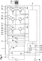
Fig. 1 is a circuit diagram of a first embodiment of aninverter 1 comprising apower unit 2, a DC link 3, acontrol unit 4, asupply unit 5 and ameasuring unit 6. Theinverter 1 converts DC voltage provided by a high-voltage battery 7 and connected via a contactor 8 to the DC link 3 into a three-phase AC output current, which is provided by thepower unit 2, being connected tostator windings 9 of anelectric machine 10. Theelectric machine 10 is a permanent magnet synchronous motor of an electric vehicle. - The
power unit 2 comprises threehalf bridges 11a-c each having afirst switching element 12a-c connected to a first potential 13 being a high potential of the DC link 3 and asecond switching element 14a-c connected to a second potential 15 being a low potential of the DC link 3. Each switchingelement 12a-c, 14a-c is formed by atransistor 16 and a freewheelingdiode 17 connected in parallel. Thetransistor 16 is an insulated gate bipolar transistor. Alternatively, thetransistor 16 may be a metal oxide semiconductor field-effect transistor, wherein thediode 17 is formed by a body diode of thetransistor 16. Acontrol terminal 18 of each switchingelement 12a-c, 14a-c is connected to adriver element 19 configured to amplify signals provided by thecontrol unit 4. Thedriver elements 19 form a driver unit of theinverter 1. - The
supply unit 5 obtains a supply voltage of e.g. 12 V provided by alow voltage battery 20 of the vehicle. Furthermore, thesupply unit 5 comprises a DC/DC-converter 21 connected to the DC link 3. Thesupply unit 5 supplies an operating voltage to thecontrol unit 4 into the driver unit, wherein the wiring between thesupply unit 5 and the driver unit is not depicted for reasons of simplicity. The output of the DC/DC-converter 21 provides a voltage that is e.g. 0.5 V lower than the voltage of the low-voltage battery 20. Due todiodes converter 21 and thelow voltage battery 20 on an anode side and to thecontrol unit 4 and the driver unit on a cathode side, the higher supply voltage of thelow voltage battery 20 is dominant. - Furthermore, the
measurement unit 6 comprises a firstvoltage measurement device 24 and a secondvoltage measurement device 25, which are connected in parallel to a smoothingcapacitor 26 forming the DC link 3. Measured voltages by thevoltage measurement devices control unit 4. -
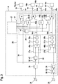
Fig. 2 is a block diagram of thecontrol unit 4 of theinverter 1. Thecontrol unit 4 comprises amodulation section 27, a controllingsection 28, an analog insulatedamplifier section 29 and acomparator section 30. - The
modulation section 27 is configured to provide pulse-width-modulated pulsing signals 31 such that theswitching elements 12a-c, 14a-c are turned on and off for providing the AC output current by theinverter 1 in a normal, i.e. failure-free, operation mode. The modulation section is realized by a microcontroller having a software, which determines the pulsing signals 31. The pulsing signals 31 are provided to the controllingsection 28. Themodulation section 27 is part of a low-voltage side of theinverter 1. - The analog insulated
amplifier section 29 receives a raw measuring signal from the firstvoltage measuring device 24 being part of a high-voltage side of theinverter 1 and provides ananalog signal 32 representing the DC link voltage as measured electric parameter to the controllingsection 28. The analog insulatedamplifier section 29 forms an interface between the high-voltage side and the low-voltage side. - The
comparator section 30 comprises acomparator element 33 and adigital optocoupler 34, which forms an interface between the high-voltage side and the low voltage side. Thecomparator element 33 receives a second measuring signal from the secondvoltage measuring device 25 and is part of the high-voltage side of theinverter 1. - The controlling
section 28 is realized separately from thecomparator section 30 discretely or by a complex programmable logic device or by a field programmable gate array. The controlling section is part of the low-voltage side of theinverter 1. The controllingsection 28 comprises afirst subsection 35, which obtains the pulsing signals 31 and asignal 36 from asecond subsection 37. Furthermore, thefirst subsection 35 receives arequest signal 38, which requests to adopt a safe state. Therequest signal 38 may be generated by thecontrol unit 4 itself or may be received from another unit of theinverter 1 or from a controller of the vehicle. - In the normal operation mode of the inverter 1 a NOT-gate 39 of the
first subsection 35 has a logic zero input signal, representing that therequest signal 38 is not received. The output of the NOT-gate 39 and pulsing signals 31 for controlling thefirst switching elements 12a-c are the input of an AND-gate 40 for eachfirst switching element 12a-c, wherein only one AND-gate 40 is depicted inFig. 2 for reasons of simplicity. Afirst signal 41 output by each AND-gate 40 corresponds to a respective pulsing signals 31 since the NOT-gate 39 provides a logic one output as long as therequest signal 38 is not received. - A
pulsing signal 31 for controlling thesecond switching element 14a is an input of an OR-gate 42, which also has therequest signal 38 being delayed by adelay element 43 as input. Thus, as long as therequest signal 38 is not received and the delay time of thedelay element 43 has not elapsed the OR-gate 43 outputs thepulsing signal 31. The output of the OR-gate 43 and thesignal 36 are the input of an AND-gate 44. As described later on, the normal operating mode thesignal 36 is a logic one. Thus, in the normal operation thesecond signal 45a output by the AND-gate 44 corresponds to thepulsing signal 31 for controlling thesecond switching element 14a. - The pulsing signals 31 for controlling the
second switching elements gates 46. Thus, as long as therequest signal 38 is not received and the delay time of thedelay element 43 has not elapsed the OR-gates 46 output the pulsing signals 31. Thus, in the normal operation mode second signals 45b, 45c correspond to the pulsing signals for controlling thesecond switching elements - In the following the receipt of the
request signal 38 being represented by a logic one, which is input into thedelay element 43 and into the NOT-gate 39, is described in detail: - The
control unit 4 is configured to provide thefirst signals 41 to thefirst switching elements 12a-c such that they are turned off upon receiving therequest signal 38. Thus, when a logic one is fed into the NOT-gate 39, it outputs a logic zero causing the AND-gate 40 to output a logic zero as well. Accordingly, thefirst signals 41 cause thedriver elements 19 to provide voltages to thecontrol terminals 18 of thefirst switching elements 12a-c, which turn them off. - Furthermore, the
control unit 4 is configured to provide thesecond signals 45a-c to thesecond switching elements 14a-c such that they are turned on upon receiving therequest signal 38. With respect to thesecond switching element 14a the output of the OR-gate 42 is a logic one after the delay time has elapsed. As thesignal 36 is still a logic one, the output of the AND-gate 44 is a logic one causing thedriver element 19 to provide a voltage to thecontrol terminal 18 of thesecond switching element 14a, which turns it on. With respect to thesecond switching elements gates 46 are a logic one after the delay time has elapsed. The outputs of the OR-gates 46 cause thedriver elements 19 to provide voltages to thecontrol terminals 18 of thesecond switching elements - By adopting the afore-mentioned switching configuration of the
switching elements 12a-c, 14a-c a full active short circuit (ASC) as safe state is realized, in which thestator windings 9 of theelectric machine 10 are short-circuited. Therein, thedelay element 43, which has a delay time of approximately 4 µs avoids a short circuit of thehalf brides 11a-c. - However, a voltage supply by the
supply unit 5 is necessary to keep the ASC because theswitching elements 12a-c, 14a-c are normally off. Therefore, in the case of losing the supply voltage of thelow voltage battery 20 an emergency voltage supply is realized by the DC/DC-converter 21, which obtains the high voltage of the DC link 3. However, due to safety measures the contactor 8 may be opened due to the same reason that triggers therequest signal 38. Then the DC/DC-converter 21 cannot any longer supply thecontrol unit 4 and the driver unit, when the smoothingcapacitor 26 is discharged. Therefore, thecontrol unit 4 allows the smoothing capacitor to be periodically recharged by a voltage recovered from thestator windings 9. - For recharging the smoothing
capacitor 26, thecontrol unit 4 is configured to provide thesecond signal 45a such that thesecond switching element 14a is turned off for a predefined first time span of 4 µs and turned on for a predefined second time span of 270 µs after the first time span has elapsed, if a switching criterion is fulfilled. By turning off thesecond switching element 14a, both switchingelements half bridge 11a are turned off. This results in thediodes 17 working as a rectifier, which rectifies a recovered voltage from thestator windings 9. The recovered voltage is used for recharging the smoothingcapacitor 26. Note that by turning off theswitching elements - For evaluating the switching criterion, the
control unit 4, in particular the controllingsection 28, is configured to perform a first comparison of the voltage by acomparator element 47 and receiving theanalog signal 32 from the analog insulatedamplifier section 29. Thecomparator element 47 is configured to perform a first comparison of the voltage of the DC link 3 represented by theanalog signal 32 with a threshold value, which is chosen to 40 V. Correspondingly, thecomparator element 33 of thecomparator section 30 performs a second comparison of the voltage of the DC link 3 represented by the measuring signal of thesecond measuring device 25 with the threshold value. The result of the second comparison, which has been performed on the high-voltage side of the inverter, is then provided to thesecond subsection 37. - The switching criterion comprises the first condition that the first comparison results in that the voltage reaches or falls below the threshold value, the second condition that the second comparison results in that the voltage reaches or crosses the threshold value and a third condition that the low voltage supply for the
control unit 4 and the driver unit by thelow voltage battery 25 is not present. In order to check the third condition asignal 48 is provided, which is generated by thecontrol unit 4 or obtained by another unit of theinverter 1 or by a controller of the vehicle. - For evaluating the switching criterion, the
second subsection 37 comprises an AND-gate 49 having an output of thecomparator element 47 and an output of thecomparator section 30 as input. Furthermore, thesecond subsection 37 comprises an AND-gate 50 having the output of the AND-gate 49 and thesignal 48 as input. Thus, when the switching criterion is fulfilled, the AND-gate 50 outputs a logic one. - In order to ensure that the
second switching element 14a is turned off for the first time span and turned on for the second time span, thesecond subsection 37 comprises atiming element 51, which outputs a logic one during the first time span and outputs subsequently a logic zero during the second time span. An output of thetiming element 51 is the input of a NOT-gate 52, which outputs thesignal 36. - Thus, during the first time span the
signal 36 is a logic zero causing thesecond signal 45a to be a logic zero, which causes thesecond switching element 14a to turn off and theinverter 1 to adopt the partial ASC. Therein, the smoothingcapacitor 26 is recharged. Correspondingly, during the second time span thesignal 36 is a logic one causing thesecond signal 45 a to be a logic one, which causes theswitching element 14a to turn on again and theinverter 1 to adopt the full ASC again. Therein, the smoothing capacitor is discharged by the DC/DC-converter 21. - Optionally, the
control unit 4 comprises adiagnose section 53 which obtains the output of the AND-gate 49. Thediagnose section 53 is configured to evaluate, whether on a startup of theinverter 1, while the smoothingcapacitor 26 is charged initially, the output of the AND-gate 49 changes from a logic zero to a logic one. Thereby, the diagnose section determines whether themeasurement devices comparator section 30 and thecomparator element 47 work properly as the voltage of the DC link 3 rises from 0 V to the voltage of the high voltage battery 7. If the change is not detected, thediagnose section 53 provides therequest signal 38 resulting in adopting the full ASC. - According to a further embodiment of an
inverter 1, which corresponds to the first embodiment, thesecond subsection 37 comprises an OR-gate instead of the AND-gate 49. - According to a further embodiment of an
inverter 1 which corresponds to any of the aforementioned embodiments, thesecond measuring device 25, thecomparator section 30 and the AND-gate 49 are omitted. The output of thecomparator element 47 is fed directly into the AND-gate 50 and optionally into thediagnose section 53. - According to a further embodiment of an
inverter 1, which corresponds to any of the aforementioned embodiments, thefirst measuring device 24, thecomparator element 47 and the AND-gate 49 are omitted. The output of thecomparator section 30 is fed directly into the AND-gate 50 and optionally into thediagnose section 53. -
Fig. 3 is a block diagram of acontrol unit 4 of a further embodiment of aninverter 1, which corresponds to the first embodiment. In the following the differences in comparison to the first embodiment are described: - The
second switching element 14a is controlled by a logic formed by an OR-gate 42a and an AND-gate 44a corresponding to the OR-gate 42 and the AND-gate 44 depicted inFig. 1 , wherein a second subsection provides asignal 36a, which is an input of the AND-gate 44a. In contrast toFig. 1 thesecond switching element 14c is controlled by a similar logic formed by an OR-gate 42b and an AND-gate 44b, wherein athird subsection 37b provides asignal 36b, which is an input of the AND-gate 44b. - The
second subsection 37a comprises only one AND-gate 49a having the output of thecomparator element 47 and thesignal 48 as input. Atiming element 51 a corresponding to thetiming element 51a inFig. 1 has the output of the AND-gate 49a as input. A NOT-gate 52a has the output of thetiming element 51 a as input and provides thesignal 36a to thefirst subsection 35. Thus, thesecond subsection 37a is configured to evaluate a first switching criterion comprising the first condition that the first comparison results in that the voltage reaches or falls below the threshold value and the third condition that the low voltage supply for thecontrol unit 4 and the driver unit by thelow voltage battery 25 is not present. The result of the evaluation of the first switching criterion is represented by thesignal 36a. - The
third subsection 37b comprises an AND-gate 49b, atiming element 51b and a NOT-gate 52b corresponding to thesecond subsection 37a, wherein the AND-gate 49b has the output of thecomparator section 30 as input instead of the input of thecomparator element 47. Thus, thethird subsection 37b is configured to evaluate a second switching criterion comprising a second condition that the second comparison results in that the voltage reaches of falls below the threshold value and the third condition. The result of the evaluation of the second switching criterion is represented by thesignal 36b. - Thus, the
inverter 1 according to the present embodiment recharges the smoothingcapacitor 26 by using thehalf bridges - According to a further embodiment corresponding to the one depicted in
Fig. 3 thetiming elements - According to a further embodiment corresponding to any of the aforementioned ones the first potential 13 is a low potential and the second potential 15 is the high potential.
- According to a further embodiment corresponding to any of the aforementioned ones the measuring
devices - According to a further embodiment corresponding to any of the aforementioned ones, the controlling
section 28 is realized by a microcontroller, wherein the logic gates, thecomparator element 47, thetiming elements delay element 43 are realized by corresponding software routines of a program loaded into the microcontroller.
Claims (15)
- Control unit (4) for controlling an inverter (1) with a plurality of half bridges (11a-c) each having a first switching element (12a-c) connected to a potential (13) of a DC link (3) and a second switching element (14a-c) connected to another potential (15) of the DC link (3), wherein the control unit (4) is configured to provide first signals (41) to the first switching elements (12a-c) such that they are turned off upon receiving a request signal (38), to provide second signals (45a-c) to the second switching elements (14a-c) such that they are turned on upon receiving the request signal (38) and to perform a comparison of a measured electric parameter of the inverter (1) with a predefined threshold value, characterized in that the control unit (4) is configured to provide a second signal (45a) such that the second switching element (14a) controlled by the second signal (45a) is turned off for a predefined time span, if a switching criterion comprising a condition that the comparison results in that the measured electric parameter reaches or crosses the threshold value is fulfilled.
- Control unit (4) for controlling an inverter (1) with a plurality of half bridges (11a-c) each having a first switching element (12a-c) connected to a potential (13) of a DC link (3) and a second switching element (14a-c) connected to another potential (15) of the DC link (3), wherein the control unit (4) is configured to provide first signals (41) to the first switching elements (12a-c) such that they are turned off upon receiving a request signal (38), to provide second signals (45a-c) to the second switching elements (14a-c) such that they are turned on upon receiving the request signal (38) and to perform a comparison of a measured electric parameter of the inverter (1) with a predefined threshold value, characterized in that the control unit (4) is configured to provide a second signal (45a) such that the second switching element (14a) controlled by the second signal (45a) is turned off and a second signal (45b, c) to another second switching element (14b, c) such that the second switching element (14b, c) is turned on, if a switching criterion comprising a condition that the comparison results in that the measured electric parameter reaches or crosses the threshold value is fulfilled.
- Control unit (4) according to claim 2, wherein the second switching element (14a) controlled by the second signal (45a) is turned off for a predefined time span.
- Control unit (4) according to claim 1 or 3, wherein the control unit (4) is configured to provide the second signal (45a) such that the second switching element (14a) is turned on for a predefined second time span after the first time span has elapsed.
- Control unit (4) according to any of the preceding claims, wherein the measured electric parameter is a voltage or a current of the DC link (3).
- Control unit (4) according to any of the preceding claims, wherein the control unit (4) comprises a controlling section (28) being realized discretely or by a complex programmable logic unit or by a field programmable gate array or by a microcontroller and being configured to evaluate the switching criterion and to perform the comparison based upon a low-voltage analog signal (32) representing the measured electric parameter and being provided to the controlling section (28).
- Control unit (4) according to any of the preceding claims, wherein the control unit (4) is configured to perform a second comparison of the measured electric parameter with the threshold value.
- Control unit (4) according to claims 6 and 7, wherein the control unit (4) comprises a comparator section for performing the second comparison being realized separately from the controlling section and being configured to provide a digital signal representing the result of the second comparison.
- Control unit (4) according to claim 7 or 8, wherein the switching criterion comprises an additional or alternative condition that the second comparison results in that the measured electric parameter reaches or crosses the threshold value.
- Control unit (4) according to claim 7 or 8, wherein the control unit (4) is configured to provide a further second signal (45c) such that another second switching element (14b, c) controlled by the further second signal (45c) is turned off, if a second switching criterion comprising a condition that the second comparison results in that the measured electric parameter reaches or crosses the threshold value.
- Control unit (4) according to any of the preceding claims, wherein the switching criterion or the switching criteria comprise a further condition that a low-voltage supply for the control unit (4) and/or a driver unit of the inverter (1) is not present.
- Control unit (4) according to any of the preceding claims, wherein the control unit (4) is configured to provide the first signals (41) directly upon receiving the request signal (38) at the signal input port and/or to provide the second signal (45a-c) after having delayed the request signal (38) by a delay element (43).
- Inverter (1) for a vehicle, comprising a smoothing capacitor (26) forming a DC link (3), a plurality of half bridges (11a-c) each having a first switching element (12a-c) connected to a potential (13) of the DC link (3) and a second switching element (14a-c) connected to another potential (15) of the DC link (3), wherein the inverter (1) comprises a control unit (4) according to any of claims 1 to 12.
- Method for operating an inverter (1) with a plurality of half bridges (11a-c) each having a first switching element (12a-c) connected to a potential (13) of a DC link (3) and a second switching element (14a-c) connected to another potential (15) of the DC link (3), wherein first signals (41) are provided to the first switching elements (12a-c) such that they are turned off upon receiving a request signal (38), second signals (45a-c) are provided to the second switching elements (14a-c) such that they are turned on upon receiving the request signal (38) and a comparison of a measured electric parameter of the inverter (1) with a predefined threshold value is performed, wherein a second signal (45a) is provided such that the second switching element (14a) controlled by the second signal (45a) is turned off for a predefined time span, if a switching criterion comprising a condition that the comparison results in that the measured electric parameter reaches or crosses the threshold value is fulfilled.
- Method for operating an inverter (1) with a plurality of half bridges (11a-c) each having a first switching element (12a-c) connected to a potential (13) of a DC link (3) and a second switching element (14a-c) connected to another potential (15) of the DC link (3), wherein first signals (41) are provided to the first switching elements (12a-c) such that they are turned off upon receiving a request signal (38), second signals (45a-c) are provided to the second switching elements (14a-c) such that they are turned on upon receiving the request signal (38) and a comparison of a measured electric parameter of the inverter (1) with a predefined threshold value is performed, wherein a second signal (45a) is provided such that the second switching element (14a) controlled by the second signal (45a) is turned off and a second signal (45b, c) to another second switching element (14b, c) is provided such that the second switching element (14b, c) is turned on, if a switching criterion comprising a condition that the comparison results in that the measured electric parameter reaches or crosses the threshold value is fulfilled.
Priority Applications (5)
| Application Number | Priority Date | Filing Date | Title |
|---|---|---|---|
| EP17205695.4A EP3496260A1 (en) | 2017-12-06 | 2017-12-06 | Control unit for controlling an inverter, inverter and method for operating an inverter |
| CN201811418999.6A CN109889068A (en) | 2017-12-06 | 2018-11-26 | A kind of method of inverter and its control unit and operation |
| JP2018226388A JP7190886B2 (en) | 2017-12-06 | 2018-12-03 | CONTROL UNIT FOR INVERTER CONTROL, INVERTER, AND INVERTER DRIVING METHOD |
| US16/209,543 US10972017B2 (en) | 2017-12-06 | 2018-12-04 | Control unit for controlling an inverter, inverter and method for operating an inverter |
| KR1020180155390A KR102638052B1 (en) | 2017-12-06 | 2018-12-05 | Control unit for controlling an inverter, inverter and method for operating an inverter |
Applications Claiming Priority (1)
| Application Number | Priority Date | Filing Date | Title |
|---|---|---|---|
| EP17205695.4A EP3496260A1 (en) | 2017-12-06 | 2017-12-06 | Control unit for controlling an inverter, inverter and method for operating an inverter |
Publications (1)
| Publication Number | Publication Date |
|---|---|
| EP3496260A1 true EP3496260A1 (en) | 2019-06-12 |
Family
ID=60627479
Family Applications (1)
| Application Number | Title | Priority Date | Filing Date |
|---|---|---|---|
| EP17205695.4A Pending EP3496260A1 (en) | 2017-12-06 | 2017-12-06 | Control unit for controlling an inverter, inverter and method for operating an inverter |
Country Status (5)
| Country | Link |
|---|---|
| US (1) | US10972017B2 (en) |
| EP (1) | EP3496260A1 (en) |
| JP (1) | JP7190886B2 (en) |
| KR (1) | KR102638052B1 (en) |
| CN (1) | CN109889068A (en) |
Cited By (1)
| Publication number | Priority date | Publication date | Assignee | Title |
|---|---|---|---|---|
| EP4230464A1 (en) | 2022-02-18 | 2023-08-23 | hofer powertrain innovation GmbH | Distributed control and safety system for a motor vehicle with at least one inverter and a corresponding method |
Families Citing this family (3)
| Publication number | Priority date | Publication date | Assignee | Title |
|---|---|---|---|---|
| DE102019200181A1 (en) * | 2018-01-15 | 2019-07-18 | Continental Teves Ag & Co. Ohg | Method of control, drive circuit, brake system and use |
| DE102019212377A1 (en) * | 2019-08-14 | 2021-02-18 | Vitesco Technologies GmbH | Circuit arrangement for discharging at least one energy store charged to a high voltage |
| EP4002664A1 (en) * | 2020-11-11 | 2022-05-25 | Valeo Siemens eAutomotive Germany GmbH | Inverter, method for configuring an inverter, method for controlling an inverter and corresponding computer program |
Citations (4)
| Publication number | Priority date | Publication date | Assignee | Title |
|---|---|---|---|---|
| EP2433830A1 (en) | 2010-09-28 | 2012-03-28 | Brusa Elektronik AG | Method and control for providing electrical energy from a driven alternating current synchronous machine |
| US9007011B2 (en) * | 2012-02-09 | 2015-04-14 | Minebea Co., Ltd. | Driving control device of brushless motor |
| US20150214858A1 (en) * | 2012-09-10 | 2015-07-30 | Robert Bosch Gmbh | Operating state circuit for an inverter and method for setting operating states of an inverter |
| DE102016010740A1 (en) * | 2016-09-03 | 2017-03-30 | Daimler Ag | Operate a drive train by short-term active short circuit |
Family Cites Families (8)
| Publication number | Priority date | Publication date | Assignee | Title |
|---|---|---|---|---|
| KR100188910B1 (en) * | 1996-02-08 | 1999-06-01 | 김정국 | A failure detecting circuit of a converter |
| KR19990015695A (en) * | 1997-08-08 | 1999-03-05 | 이종수 | Induction Motor Drive |
| US9521437B2 (en) | 2009-06-17 | 2016-12-13 | Google Technology Holdings LLC | Insertion of recorded secondary digital video content during playback of primary digital video content |
| JP4962583B2 (en) * | 2010-03-11 | 2012-06-27 | 株式会社デンソー | Discharge control device for power conversion system |
| JP5547559B2 (en) * | 2010-06-16 | 2014-07-16 | 日立オートモティブシステムズ株式会社 | Power converter |
| DE102014223236A1 (en) * | 2014-11-14 | 2016-05-19 | Robert Bosch Gmbh | Power converter and method for operating a power converter |
| US9645185B2 (en) * | 2015-03-05 | 2017-05-09 | Ford Global Technologies, Llc | AC traction motor fault detection using DC bus leakage hardware |
| CN105514941A (en) * | 2015-12-31 | 2016-04-20 | 联合汽车电子有限公司 | Electric vehicle inverter protective device and method |
-
2017
- 2017-12-06 EP EP17205695.4A patent/EP3496260A1/en active Pending
-
2018
- 2018-11-26 CN CN201811418999.6A patent/CN109889068A/en active Pending
- 2018-12-03 JP JP2018226388A patent/JP7190886B2/en active Active
- 2018-12-04 US US16/209,543 patent/US10972017B2/en active Active
- 2018-12-05 KR KR1020180155390A patent/KR102638052B1/en active IP Right Grant
Patent Citations (4)
| Publication number | Priority date | Publication date | Assignee | Title |
|---|---|---|---|---|
| EP2433830A1 (en) | 2010-09-28 | 2012-03-28 | Brusa Elektronik AG | Method and control for providing electrical energy from a driven alternating current synchronous machine |
| US9007011B2 (en) * | 2012-02-09 | 2015-04-14 | Minebea Co., Ltd. | Driving control device of brushless motor |
| US20150214858A1 (en) * | 2012-09-10 | 2015-07-30 | Robert Bosch Gmbh | Operating state circuit for an inverter and method for setting operating states of an inverter |
| DE102016010740A1 (en) * | 2016-09-03 | 2017-03-30 | Daimler Ag | Operate a drive train by short-term active short circuit |
Cited By (1)
| Publication number | Priority date | Publication date | Assignee | Title |
|---|---|---|---|---|
| EP4230464A1 (en) | 2022-02-18 | 2023-08-23 | hofer powertrain innovation GmbH | Distributed control and safety system for a motor vehicle with at least one inverter and a corresponding method |
Also Published As
| Publication number | Publication date |
|---|---|
| KR20190067109A (en) | 2019-06-14 |
| CN109889068A (en) | 2019-06-14 |
| US20190173395A1 (en) | 2019-06-06 |
| JP7190886B2 (en) | 2022-12-16 |
| KR102638052B1 (en) | 2024-02-16 |
| JP2019103388A (en) | 2019-06-24 |
| US10972017B2 (en) | 2021-04-06 |
Similar Documents
| Publication | Publication Date | Title |
|---|---|---|
| US10972017B2 (en) | Control unit for controlling an inverter, inverter and method for operating an inverter | |
| CN105281552B (en) | Gate drive under-voltage detection | |
| US10998808B2 (en) | Power conversion device | |
| KR102087573B1 (en) | Operating state circuit for an inverter and method for setting operating states of an inverter | |
| WO2013190733A1 (en) | Leak detection device | |
| EP3501876B1 (en) | Control unit, inverter, assembly, vehicle and method for controlling an inverter | |
| US10525838B2 (en) | Power conversion system | |
| US20140049215A1 (en) | Method for monitoring the charging mode of an energy store in a vechile and charging system for charging an energy store in a vechile | |
| US9586789B2 (en) | Elevator braking in a battery powered elevator system | |
| US20160276823A1 (en) | Power supply system | |
| EP2544346A1 (en) | Load driving device | |
| CN103548266A (en) | Method and apparatus for operating a power output stage | |
| US20130229208A1 (en) | Drive circuit for switching elements | |
| CN116114163A (en) | Arrangement and method for discharging a DC link capacitor | |
| CN105429500A (en) | Inverter circuit for an electric machine | |
| CN113711481B (en) | Driving circuit | |
| JP2016093018A (en) | Inverter control device | |
| US11012021B2 (en) | Inverter device and control circuit therefor, and motor driving system | |
| JP5565087B2 (en) | Discharge device for power conversion system | |
| JP2021065039A (en) | Switch drive device | |
| JP2018057225A (en) | Inverter device | |
| US11703543B2 (en) | Power conversion device | |
| US20230396192A1 (en) | Method for operating an electric machine, especially in a motor vehicle, and a motor vehicle | |
| JP2011244522A (en) | Discharge controller of power conversion system | |
| JP5926796B2 (en) | Leak detector |
Legal Events
| Date | Code | Title | Description |
|---|---|---|---|
| PUAI | Public reference made under article 153(3) epc to a published international application that has entered the european phase |
Free format text: ORIGINAL CODE: 0009012 |
|
| STAA | Information on the status of an ep patent application or granted ep patent |
Free format text: STATUS: THE APPLICATION HAS BEEN PUBLISHED |
|
| AK | Designated contracting states |
Kind code of ref document: A1 Designated state(s): AL AT BE BG CH CY CZ DE DK EE ES FI FR GB GR HR HU IE IS IT LI LT LU LV MC MK MT NL NO PL PT RO RS SE SI SK SM TR |
|
| AX | Request for extension of the european patent |
Extension state: BA ME |
|
| STAA | Information on the status of an ep patent application or granted ep patent |
Free format text: STATUS: REQUEST FOR EXAMINATION WAS MADE |
|
| 17P | Request for examination filed |
Effective date: 20191205 |
|
| RBV | Designated contracting states (corrected) |
Designated state(s): AL AT BE BG CH CY CZ DE DK EE ES FI FR GB GR HR HU IE IS IT LI LT LU LV MC MK MT NL NO PL PT RO RS SE SI SK SM TR |
|
| STAA | Information on the status of an ep patent application or granted ep patent |
Free format text: STATUS: EXAMINATION IS IN PROGRESS |
|
| 17Q | First examination report despatched |
Effective date: 20200324 |
|
| STAA | Information on the status of an ep patent application or granted ep patent |
Free format text: STATUS: EXAMINATION IS IN PROGRESS |
|
| STAA | Information on the status of an ep patent application or granted ep patent |
Free format text: STATUS: EXAMINATION IS IN PROGRESS |
|
| RAP3 | Party data changed (applicant data changed or rights of an application transferred) |
Owner name: VALEO EAUTOMOTIVE GERMANY GMBH |
|
| P01 | Opt-out of the competence of the unified patent court (upc) registered |
Effective date: 20230528 |
|
| RIC1 | Information provided on ipc code assigned before grant |
Ipc: H02M 1/00 20060101ALN20240129BHEP Ipc: H02P 29/02 20160101ALN20240129BHEP Ipc: H02P 3/18 20060101ALN20240129BHEP Ipc: H02M 1/08 20060101ALN20240129BHEP Ipc: H02M 1/32 20070101ALN20240129BHEP Ipc: B60L 3/04 20060101ALI20240129BHEP Ipc: H02P 27/06 20060101ALI20240129BHEP Ipc: H02M 7/5387 20070101AFI20240129BHEP |
|
| GRAP | Despatch of communication of intention to grant a patent |
Free format text: ORIGINAL CODE: EPIDOSNIGR1 |
|
| STAA | Information on the status of an ep patent application or granted ep patent |
Free format text: STATUS: GRANT OF PATENT IS INTENDED |
|
| RIC1 | Information provided on ipc code assigned before grant |
Ipc: H02M 1/00 20060101ALN20240223BHEP Ipc: H02P 29/02 20160101ALN20240223BHEP Ipc: H02P 3/18 20060101ALN20240223BHEP Ipc: H02M 1/08 20060101ALN20240223BHEP Ipc: H02M 1/32 20070101ALN20240223BHEP Ipc: B60L 3/04 20060101ALI20240223BHEP Ipc: H02P 27/06 20060101ALI20240223BHEP Ipc: H02M 7/5387 20070101AFI20240223BHEP |
|
| RIC1 | Information provided on ipc code assigned before grant |
Ipc: H02M 1/00 20060101ALN20240304BHEP Ipc: H02P 29/02 20160101ALN20240304BHEP Ipc: H02P 3/18 20060101ALN20240304BHEP Ipc: H02M 1/08 20060101ALN20240304BHEP Ipc: H02M 1/32 20070101ALN20240304BHEP Ipc: B60L 3/04 20060101ALI20240304BHEP Ipc: H02P 27/06 20060101ALI20240304BHEP Ipc: H02M 7/5387 20070101AFI20240304BHEP |
|
| INTG | Intention to grant announced |
Effective date: 20240318 |