EP3494381B1 - Absorption cavity with input and output waveguides for a biological or chemical sensor - Google Patents
Absorption cavity with input and output waveguides for a biological or chemical sensor Download PDFInfo
- Publication number
- EP3494381B1 EP3494381B1 EP17765222.9A EP17765222A EP3494381B1 EP 3494381 B1 EP3494381 B1 EP 3494381B1 EP 17765222 A EP17765222 A EP 17765222A EP 3494381 B1 EP3494381 B1 EP 3494381B1
- Authority
- EP
- European Patent Office
- Prior art keywords
- waveguide
- absorption cavity
- injection
- extraction
- cavity
- Prior art date
- Legal status (The legal status is an assumption and is not a legal conclusion. Google has not performed a legal analysis and makes no representation as to the accuracy of the status listed.)
- Active
Links
- 238000010521 absorption reaction Methods 0.000 title claims description 134
- 239000000126 substance Substances 0.000 title claims description 20
- 238000002347 injection Methods 0.000 claims description 70
- 239000007924 injection Substances 0.000 claims description 70
- 238000000605 extraction Methods 0.000 claims description 64
- 238000004458 analytical method Methods 0.000 claims description 45
- 230000003287 optical effect Effects 0.000 claims description 23
- 230000008878 coupling Effects 0.000 claims description 12
- 238000010168 coupling process Methods 0.000 claims description 12
- 238000005859 coupling reaction Methods 0.000 claims description 12
- 238000005253 cladding Methods 0.000 claims description 4
- NCGICGYLBXGBGN-UHFFFAOYSA-N 3-morpholin-4-yl-1-oxa-3-azonia-2-azanidacyclopent-3-en-5-imine;hydrochloride Chemical compound Cl.[N-]1OC(=N)C=[N+]1N1CCOCC1 NCGICGYLBXGBGN-UHFFFAOYSA-N 0.000 claims description 2
- 238000009432 framing Methods 0.000 claims 1
- 230000006978 adaptation Effects 0.000 description 16
- 238000005259 measurement Methods 0.000 description 15
- 230000035945 sensitivity Effects 0.000 description 13
- 239000000758 substrate Substances 0.000 description 13
- XUIMIQQOPSSXEZ-UHFFFAOYSA-N Silicon Chemical compound [Si] XUIMIQQOPSSXEZ-UHFFFAOYSA-N 0.000 description 10
- 239000010703 silicon Substances 0.000 description 10
- 229910052710 silicon Inorganic materials 0.000 description 9
- PCHJSUWPFVWCPO-UHFFFAOYSA-N gold Chemical compound [Au] PCHJSUWPFVWCPO-UHFFFAOYSA-N 0.000 description 7
- 239000010931 gold Substances 0.000 description 7
- 229910052737 gold Inorganic materials 0.000 description 7
- 230000005540 biological transmission Effects 0.000 description 5
- GNPVGFCGXDBREM-UHFFFAOYSA-N germanium atom Chemical group [Ge] GNPVGFCGXDBREM-UHFFFAOYSA-N 0.000 description 5
- 239000007788 liquid Substances 0.000 description 5
- 229910000927 Ge alloy Inorganic materials 0.000 description 4
- 229910000676 Si alloy Inorganic materials 0.000 description 4
- 238000013459 approach Methods 0.000 description 4
- 239000011248 coating agent Substances 0.000 description 4
- 238000000576 coating method Methods 0.000 description 4
- 230000007423 decrease Effects 0.000 description 4
- 230000010354 integration Effects 0.000 description 4
- VYPSYNLAJGMNEJ-UHFFFAOYSA-N Silicium dioxide Chemical compound O=[Si]=O VYPSYNLAJGMNEJ-UHFFFAOYSA-N 0.000 description 3
- 239000002245 particle Substances 0.000 description 3
- 230000001902 propagating effect Effects 0.000 description 3
- 230000002745 absorbent Effects 0.000 description 2
- 239000002250 absorbent Substances 0.000 description 2
- 238000001514 detection method Methods 0.000 description 2
- 235000021183 entrée Nutrition 0.000 description 2
- 238000000407 epitaxy Methods 0.000 description 2
- 238000004519 manufacturing process Methods 0.000 description 2
- 230000010363 phase shift Effects 0.000 description 2
- 229920000297 Rayon Polymers 0.000 description 1
- 229910052581 Si3N4 Inorganic materials 0.000 description 1
- 229910004298 SiO 2 Inorganic materials 0.000 description 1
- 229910045601 alloy Inorganic materials 0.000 description 1
- 239000000956 alloy Substances 0.000 description 1
- 238000009412 basement excavation Methods 0.000 description 1
- 238000003486 chemical etching Methods 0.000 description 1
- 230000001186 cumulative effect Effects 0.000 description 1
- 230000003247 decreasing effect Effects 0.000 description 1
- 230000001419 dependent effect Effects 0.000 description 1
- 238000009792 diffusion process Methods 0.000 description 1
- 238000005530 etching Methods 0.000 description 1
- 238000011049 filling Methods 0.000 description 1
- 238000001914 filtration Methods 0.000 description 1
- 229910052732 germanium Inorganic materials 0.000 description 1
- 238000005304 joining Methods 0.000 description 1
- 239000000463 material Substances 0.000 description 1
- 238000000034 method Methods 0.000 description 1
- 230000000644 propagated effect Effects 0.000 description 1
- 230000005855 radiation Effects 0.000 description 1
- 239000002964 rayon Substances 0.000 description 1
- 239000000377 silicon dioxide Substances 0.000 description 1
- HQVNEWCFYHHQES-UHFFFAOYSA-N silicon nitride Chemical compound N12[Si]34N5[Si]62N3[Si]51N64 HQVNEWCFYHHQES-UHFFFAOYSA-N 0.000 description 1
- 239000000243 solution Substances 0.000 description 1
- 230000003595 spectral effect Effects 0.000 description 1
- 238000011144 upstream manufacturing Methods 0.000 description 1
Images


Classifications
-
- G—PHYSICS
- G01—MEASURING; TESTING
- G01N—INVESTIGATING OR ANALYSING MATERIALS BY DETERMINING THEIR CHEMICAL OR PHYSICAL PROPERTIES
- G01N21/00—Investigating or analysing materials by the use of optical means, i.e. using sub-millimetre waves, infrared, visible or ultraviolet light
- G01N21/01—Arrangements or apparatus for facilitating the optical investigation
- G01N21/03—Cuvette constructions
- G01N21/031—Multipass arrangements
-
- G—PHYSICS
- G01—MEASURING; TESTING
- G01N—INVESTIGATING OR ANALYSING MATERIALS BY DETERMINING THEIR CHEMICAL OR PHYSICAL PROPERTIES
- G01N21/00—Investigating or analysing materials by the use of optical means, i.e. using sub-millimetre waves, infrared, visible or ultraviolet light
- G01N21/17—Systems in which incident light is modified in accordance with the properties of the material investigated
- G01N21/25—Colour; Spectral properties, i.e. comparison of effect of material on the light at two or more different wavelengths or wavelength bands
- G01N21/31—Investigating relative effect of material at wavelengths characteristic of specific elements or molecules, e.g. atomic absorption spectrometry
- G01N21/35—Investigating relative effect of material at wavelengths characteristic of specific elements or molecules, e.g. atomic absorption spectrometry using infrared light
- G01N21/3504—Investigating relative effect of material at wavelengths characteristic of specific elements or molecules, e.g. atomic absorption spectrometry using infrared light for analysing gases, e.g. multi-gas analysis
-
- G—PHYSICS
- G01—MEASURING; TESTING
- G01N—INVESTIGATING OR ANALYSING MATERIALS BY DETERMINING THEIR CHEMICAL OR PHYSICAL PROPERTIES
- G01N21/00—Investigating or analysing materials by the use of optical means, i.e. using sub-millimetre waves, infrared, visible or ultraviolet light
- G01N21/01—Arrangements or apparatus for facilitating the optical investigation
- G01N21/03—Cuvette constructions
- G01N2021/0378—Shapes
-
- G—PHYSICS
- G01—MEASURING; TESTING
- G01N—INVESTIGATING OR ANALYSING MATERIALS BY DETERMINING THEIR CHEMICAL OR PHYSICAL PROPERTIES
- G01N2201/00—Features of devices classified in G01N21/00
- G01N2201/08—Optical fibres; light guides
Landscapes
- Physics & Mathematics (AREA)
- Biochemistry (AREA)
- Health & Medical Sciences (AREA)
- Life Sciences & Earth Sciences (AREA)
- Chemical & Material Sciences (AREA)
- Analytical Chemistry (AREA)
- General Health & Medical Sciences (AREA)
- General Physics & Mathematics (AREA)
- Immunology (AREA)
- Pathology (AREA)
- Spectroscopy & Molecular Physics (AREA)
- Investigating Or Analysing Materials By Optical Means (AREA)
- Measurement Of The Respiration, Hearing Ability, Form, And Blood Characteristics Of Living Organisms (AREA)
- Investigating Or Analysing Biological Materials (AREA)
Description
L'invention concerne le domaine des capteurs biologiques ou chimiques, en particulier des capteurs de concentration en gaz.The invention relates to the field of biological or chemical sensors, in particular gas concentration sensors.
L'invention concerne plus particulièrement des capteurs comprenant une cavité destinée à recevoir un milieu biologique ou chimique, dans laquelle un faisceau d'analyse est partiellement absorbé.The invention relates more particularly to sensors comprising a cavity intended to receive a biological or chemical medium, in which an analysis beam is partially absorbed.
On connaît dans l'art antérieur des capteurs chimiques de type capteur de gaz, comprenant une cavité, dite d'absorption, dont les parois internes sont munies d'un revêtement réfléchissant.Chemical sensors of the gas sensor type are known in the prior art, comprising a so-called absorption cavity, the internal walls of which are provided with a reflective coating.
La cavité d'absorption présente des ouvertures sur l'extérieur, de sorte qu'elle se remplit du milieu gazeux environnant.The absorption cavity has openings on the outside, so that it fills with the surrounding gaseous medium.
A l'intérieur de la cavité d'absorption se trouvent une source lumineuse, pour l'émission d'un faisceau lumineux dit d'analyse, et un photo-détecteur, pour la détection d'un faisceau de mesure correspondant au faisceau d'analyse après absorption partielle par le gaz à l'intérieur de la cavité.Inside the absorption cavity are a light source, for the emission of a so-called analysis light beam, and a photo-detector, for the detection of a measurement beam corresponding to the light beam. analysis after partial absorption by the gas inside the cavity.
La cavité d'absorption présente par exemple une forme d'ellipse, avec la source lumineuse placée en un premierfoyer de l'ellipse, et le photo-détecteur placé en un second foyer de l'ellipse. Le faisceau d'analyse émis par la source lumineuse se propage dans la cavité, se réfléchit sur une paroi réfléchissante de celle-ci, et revient vers le photo-détecteur. Le faisceau d'analyse effectue ainsi deux passages dans la cavité.The absorption cavity has for example an ellipse shape, with the light source placed in a first focus of the ellipse, and the photo-detector placed in a second focus of the ellipse. The analysis beam emitted by the light source propagates in the cavity, is reflected on a reflecting wall thereof, and returns to the photo-detector. The analysis beam thus makes two passages in the cavity.
On peut alors calculer un taux d'absorption à une longueur d'onde caractéristique d'un gaz prédéterminé, pour obtenir une concentration de ce gaz dans la cavité, et donc dans le milieu gazeux environnant.We can then calculate an absorption rate at a wavelength characteristic of a predetermined gas, to obtain a concentration of this gas in the cavity, and therefore in the surrounding gaseous medium.
La mesure de concentration utilise la loi de Beer-Lambert : ![]()
- r une distance parcourue par le faisceau d'analyse dans la cavité ;
- α le coefficient d'absorption du gaz prédéterminé, coefficient lié à la nature du gaz en présence et à sa concentration ;
- I 0 l'intensité lumineuse du faisceau d'analyse, émis par la source lumineuse ; et
- I(r) l'intensité lumineuse du faisceau de mesure, mesurée par le photo-détecteur.
- r a distance traveled by the analysis beam in the cavity;
- α the predetermined gas absorption coefficient, coefficient linked to the nature of the gas present and to its concentration;
- I 0 the light intensity of the analysis beam, emitted by the light source; and
- I ( r ) the light intensity of the measurement beam, measured by the photo-detector.
La variation d'intensité lumineuse ![]()
![]()
Afin d'augmenter la sensibilité de la mesure, une solution consiste à augmenter la distance r parcourue par le faisceau d'analyse dans la cavité.In order to increase the sensitivity of the measurement, one solution consists in increasing the distance r traveled by the analysis beam in the cavity.
Le document
On connaît également dans l'art antérieur le document
On connaît aussi dans l'art antérieur le document
Un objectif de la présente invention est de proposer un dispositif optique à cavité d'absorption, pour un capteur chimique ou biologique tel qu'un capteur de gaz, permettant d'augmenter encore la sensibilité du capteur.An objective of the present invention is to provide an optical device with absorption cavity, for a chemical or biological sensor such as a gas sensor, making it possible to further increase the sensitivity of the sensor.
Cet objectif est atteint avec un dispositif optique tel que mentionné en revendication 1.This objective is achieved with an optical device as mentioned in
Le faisceau de mesure correspond au faisceau d'analyse en sortie de la cavité d'absorption, c'est-à-dire après qu'il a transité dans la cavité d'absorption.The measurement beam corresponds to the analysis beam at the output of the absorption cavity, that is to say after it has passed through the absorption cavity.
Ainsi, dans un capteur chimique ou biologique comprenant un tel dispositif optique, la source lumineuse émettant le faisceau d'analyse est déportée à l'extérieur de la cavité.Thus, in a chemical or biological sensor comprising such an optical device, the light source emitting the analysis beam is offset outside the cavity.
De la même façon, le photo-détecteur est déporté à l'extérieur de la cavité.In the same way, the photo-detector is deported outside the cavity.
On s'affranchit ainsi des contraintes liées à l'intégration d'un composant à l'intérieur d'une cavité de volume réduit.This eliminates the constraints linked to the integration of a component inside a cavity of reduced volume.
L'invention permet donc de simplifier l'intégration de la source lumineuse et du photo-détecteur, dans un capteur à cavité d'absorption.The invention therefore makes it possible to simplify the integration of the light source and the photo-detector into a sensor with an absorption cavity.
Cette intégration simplifiée peut permettre d'améliorer une précision de positionnement et d'alignement de la source lumineuse et du photo-détecteur, et donc d'améliorer la sensibilité dudit capteur.This simplified integration can make it possible to improve positioning and alignment precision of the light source and of the photo-detector, and therefore to improve the sensitivity of said sensor.
L'invention permet également d'exploiter les possibilités de l'optique guidée pour traiter le faisceau d'analyse avant son entrée dans la cavité d'absorption et/ou le faisceau de mesure sortant de la cavité d'absorption (filtrage spectral, routage, etc.).The invention also makes it possible to exploit the possibilities of guided optics to process the analysis beam before it enters the absorption cavity and / or the measurement beam leaving the absorption cavity (spectral filtering, routing , etc.).
Il est ainsi possible d'améliorer un rapport signal sur bruit sur le faisceau de mesure. Ainsi, on peut améliorer encore la sensibilité d'un capteur à cavité d'absorption.It is thus possible to improve a signal to noise ratio on the measurement beam. Thus, the sensitivity of an absorption cavity sensor can be further improved.
L'invention est particulièrement astucieuse en ce qu'elle s'affranchit des préjugés de l'homme du métier en proposant une nouvelle piste d'amélioration de la sensibilité ne reposant pas sur une nouvelle forme de la cavité d'absorption.The invention is particularly clever in that it overcomes the prejudices of those skilled in the art by proposing a new track for improving the sensitivity not based on a new form of the absorption cavity.
D'autres caractéristiques optionnelles de l'invention sont mentionnées dans les revendications dépendantes.Other optional features of the invention are mentioned in the dependent claims.
L'invention concerne également un capteur chimique ou biologique, comprenant :
- un dispositif optique selon l'invention ;
- une source lumineuse, pour l'émission du faisceau lumineux d'analyse ; et
- un photo-détecteur, pour la réception du faisceau lumineux de mesure.
- an optical device according to the invention;
- a light source, for the emission of the analysis light beam; and
- a photo-detector, for receiving the measurement light beam.
La présente invention sera mieux comprise à la lecture de la description d'exemples de réalisation donnés à titre purement indicatif et nullement limitatif, en faisant référence aux dessins annexés sur lesquels :
- les
figures 1A et 1B illustrent de façon schématique un premier mode de réalisation d'un dispositif optique et un capteur chimique ou biologique selon l'invention, selon deux vues en coupe ; - la
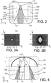
figure 2 illustre de façon schématique un détail d'un guide d'onde d'injection, respectivement un guide d'onde d'extraction selon le mode de réalisation représenté auxfigures 1A et 1B ; - les
figures 3A et 3B illustrent l'ajustement de taille de mode mis en œuvre grâce à un guide d'onde tel que représenté enfigure 2 ; - la
figure 4 illustre de façon schématique une variante du mode de réalisation représenté auxfigures 1A et 1B ; - la
figure 5 illustre de façon schématique un deuxième mode de réalisation d'un dispositif optique et un capteur chimique ou biologique selon l'invention ; - la
figure 6 illustre de façon schématique une variante du mode de réalisation représenté à lafigure 5 ; et - la
figure 7 illustre de façon schématique un exemple de procédé de réalisation d'un dispositif optique selon l'invention.
- the
Figures 1A and 1B schematically illustrate a first embodiment of an optical device and a chemical or biological sensor according to the invention, according to two sectional views; - the
figure 2 schematically illustrates a detail of an injection waveguide, respectively an extraction waveguide according to the embodiment shown inFigures 1A and 1B ; - the
Figures 3A and 3B illustrate the mode size adjustment implemented using a waveguide as shown infigure 2 ; - the
figure 4 schematically illustrates a variant of the embodiment shown inFigures 1A and 1B ; - the
figure 5 schematically illustrates a second embodiment of an optical device and a chemical or biological sensor according to the invention; - the
figure 6 schematically illustrates a variant of the embodiment shown infigure 5 ; and - the
figure 7 schematically illustrates an example of a method for producing an optical device according to the invention.
On décrit tout d'abord, en référence aux
La
La
On peut considérer que la
Le dispositif optique 100 comprend une cavité d'absorption 110, un guide d'onde d'injection 120 et un guide d'onde d'extraction 130.The
En pratique, le dispositif optique 100 est avantageusement formé dans un substrat 140, par exemple un substrat en silicium.In practice, the
La cavité d'absorption 110 est destinée à recevoir un milieu gazeux ou même liquide, qui va absorber en partie un faisceau lumineux d'analyse, l'absorption étant caractéristique d'un élément chimique ou biologique et de la concentration de cet élément.The
La cavité d'absorption 110 présente ici une forme de cylindre droit, dont la base est une demi-ellipse.The
La base est parallèle au plan (xOy) (voir
La génératrice du cylindre est parallèle à l'axe (Oz).The generator of the cylinder is parallel to the axis (Oz).
La hauteur h de la cavité est donc mesurée selon cet axe (Oz).The height h of the cavity is therefore measured along this axis (Oz).
Dans toute la suite, mais de manière non limitative, on s'intéressera plus particulièrement à cette forme de cavité d'absorption.In the following, but not limited to, we will focus more specifically on this form of absorption cavity.
Les parois internes de la cavité d'absorption 110 sont recouvertes au moins partiellement d'un revêtement réfléchissant 111, ici une fine couche d'or. Le revêtement réfléchissant 111 s'étend en particulier sur une paroi plane supérieure, une paroi plane inférieure, et une paroi latérale arrondie de la cavité 110.The internal walls of the
Le guide d'onde d'injection 120 est configuré pour guider un faisceau d'analyse 150 depuis l'extérieur de la cavité d'absorption 110, jusqu'en entrée de celle-ci.The
En particulier, le guide d'onde d'injection 120 présente une première extrémité 121 disposée en un premier foyer F1 de l'ellipse définissant la cavité d'absorption. En particulier, le centre du guide d'onde d'injection 120, à son extrémité située du côté de la cavité d'absorption 110, coïncide avec le foyer F1.In particular, the
Le guide d'onde d'injection 120 s'étend ici entièrement à l'extérieur de la cavité d'absorption 110.The
La hauteur du guide d'onde d'injection 120 est inférieure à celle de la cavité d'absorption (dimension selon l'axe (Oz)), par exemple au moins deux fois inférieure.The height of the
Le guide d'onde d'extraction 130 est configuré pour guider un faisceau de mesure 160 jusqu'à l'extérieur de la cavité d'absorption 110.The
En particulier, le guide d'onde d'extraction 130 présente une première extrémité 131 disposée en un second foyer F2 de l'ellipse définissant la cavité d'absorption. En particulier, le centre du guide d'onde d'extraction 130, à son extrémité située du côté de la cavité d'absorption 110, coïncide avec le foyer F2.In particular, the
Le guide d'onde d'extraction 130 s'étend ici entièrement à l'extérieur de la cavité d'absorption 110.The
La hauteur du guide d'onde d'extraction 130 est inférieure à celle de la cavité d'absorption, par exemple au moins deux fois inférieure.The height of the
Le capteur chimique ou biologique 1000 comprend le dispositif optique 100, une source lumineuse 1200 et un photo-détecteur 1300.The chemical or
La source lumineuse 1200 est disposée ici à une seconde extrémité 122 du guide d'onde d'injection 120.The
Il s'agit de préférence d'une source laser à cascade quantique (QCL), ou une barrette de plusieurs QCLs. En variante, il peut s'agir d'une source infra-rouge non dispersive (NDIR) en configuration guidée (et non en espace libre).It is preferably a quantum cascade laser source (QCL), or an array of several QCLs. Alternatively, it may be a non-dispersive infrared source (NDIR) in a guided configuration (and not in free space).
La source lumineuse 1200 émet le faisceau d'analyse 150, qui se propage dans le guide d'onde d'injection jusqu'à l'entrée dans la cavité d'absorption 110.The
Le faisceau d'analyse 150 traverse une première fois la cavité d'absorption en partant du premier foyer F1 de l'ellipse, se réfléchit sur le revêtement réfléchissant 111 à l'intérieur de la cavité d'absorption, et traverse une seconde fois la cavité d'absorption jusqu'à atteindre le second foyer F2 de l'ellipse et entrer dans le guide d'onde d'extraction 130.The
Au cours de ces deux traversées de la cavité d'absorption, le faisceau d'analyse est partiellement absorbé par le milieu gazeux ou liquide remplissant la cavité d'absorption.During these two passages through the absorption cavity, the analysis beam is partially absorbed by the gaseous or liquid medium filling the absorption cavity.
On nomme « faisceau de mesure » 160, le faisceau d'analyse à sa sortie de la cavité d'absorption, en entrée du guide d'onde d'extraction, ici au second foyer F2 de l'ellipse.The term “measurement beam” 160 is used to mean the analysis beam at its output from the absorption cavity, at the input of the extraction waveguide, here at the second focal point F2 of the ellipse.
Le photo-détecteur 1300 est disposé ici à une seconde extrémité 132 du guide d'onde d'extraction 130.The photo-
Il s'agit par exemple d'un détecteur infrarouge, de type bolométrique ou pyroélectrique, ou thermopile.It is for example an infrared detector, of the bolometric or pyroelectric type, or thermopile.
Il reçoit le faisceau de mesure 160, qui s'est propagé dans le guide d'onde d'extraction 130 après avoir quitté la cavité d'absorption 110.It receives the
On voit donc que le dispositif optique selon l'invention permet que la source lumineuse pour émettre le faisceau d'analyse, et le photo-détecteur pour recevoir le faisceau de mesure, soient placés à l'extérieur de la cavité d'absorption. Leur intégration est donc facilitée.It can therefore be seen that the optical device according to the invention allows the light source for emitting the analysis beam, and the photo-detector for receiving the measurement beam, to be placed outside the absorption cavity. Their integration is therefore facilitated.
La longueur d'onde centrale du faisceau d'analyse dépend de la nature de l'espèce chimique ou biologique à détecter.The central wavelength of the analysis beam depends on the nature of the chemical or biological species to be detected.
Les matériaux constituant le guide d'onde d'injection 120 et le guide d'onde d'extraction 130 sont adaptés à ladite longueur d'onde centrale.The materials constituting the
Par exemple, pour un faisceau d'analyse dans le moyen infrarouge (longueurs d'onde comprises entre 3 µm et 15 µm), les guides d'onde d'injection 120 et extraction 130 comprennent de préférence un cœur en germanium, ou un alliage de silicium et de germanium, et une gaine en silicium, ou un alliage de silicium et germanium.For example, for an analysis beam in the medium infrared (wavelengths between 3 μm and 15 μm), the
Pour un faisceau d'analyse dans le proche infrarouge (longueurs d'onde comprises entre 1 µm et 3 µm), les guides d'onde d'injection 120 et extraction 130 comprennent de préférence un cœur en silicium (Si) et une gaine en silice (SiO2).For a near infrared analysis beam (wavelengths between 1 μm and 3 μm), the
Pour un faisceau d'analyse dans le visible (longueurs d'onde inférieures à 1 µm, en particulier comprises entre 0,4 µm et 0,8 µm), les guides d'onde d'injection 120 et extraction 130 comprennent de préférence un cœur en nitrure de silicium (Si3N4) et une gaine en silice (SiO2). Un faisceau d'analyse dans le visible peut être utilisé pour détecter une espèce biologique, de préférence dans un milieu liquide, ou pour une détection de particules.For a visible analysis beam (wavelengths less than 1 μm, in particular between 0.4 μm and 0.8 μm), the
Avantageusement, mais de manière non limitative, la source lumineuse 1200 est intégrée dans un même substrat que le dispositif optique 100.Advantageously, but not limited to, the
La source lumineuse 1200 est par exemple une source thermique telle que décrite dans la demande de
En variante, la source lumineuse 1200 peut être une source laser à cascade quantique.Alternatively, the
De la même façon, le photo-détecteur 1300 est avantageusement intégré dans un même substrat que le dispositif optique 100.Likewise, the photo-
La
Le guide d'onde d'extraction 130 présente la même structure.The
Le guide d'onde d'injection 120 comprend un cœur 123, et une gaine dite principale 124 constituée ici par une portion du substrat 140 (voir
A son extrémité située du côté de la cavité d'absorption, le guide d'onde d'injection 120 est dit « en pointe ». En d'autres termes, cette extrémité est affinée, du côté de la cavité d'absorption.At its end situated on the side of the absorption cavity, the
En particulier, le cœur 123 présente une forme en pointe.In particular, the
On a défini, en référence aux
Selon la génératrice de ce cylindre, le cœur 123 présente une hauteur constante.According to the generator of this cylinder, the
Dans les plans parallèles à la base de ce cylindre, le cœur présente une forme définie par :
- deux premières parois 123A parallèles entre elles ; et
- deux deuxièmes parois 123B inclinées entre elles d'un angle β, formant ensemble une pointe dirigée vers l'intérieur de la cavité d'absorption 110.
- first two
walls 123A parallel to each other; and - two
second walls 123B inclined to each other by an angle β, together forming a point directed towards the inside of theabsorption cavity 110.
Ici, l'extrémité de la pointe présente une section carré ou rectangulaire, définie par deux troisièmes parois 123C parallèles entre elles, dont l'écartement correspond à l'écartement minimal des deux deuxièmes parois 123B.Here, the end of the tip has a square or rectangular section, defined by two
Cette extrémité à section carré ou rectangulaire permet une meilleure maîtrise de la largeur minimale du cœur 123.This square or rectangular end allows better control of the minimum width of the
Le guide d'onde d'injection 120 présente également une région dite d'adaptation 125.The
La région d'adaptation 125 présente également une hauteur constante selon la génératrice du cylindre.The
Dans les plans parallèles à la base de ce cylindre, la région d'adaptation 125 encadre une largeur décroissante de la gaine 124, puis encadre les parois 123B et 123C en forme de pointe du cœur 123, en étant en contact physique direct avec elles.In the planes parallel to the base of this cylinder, the
Ainsi, de part et d'autre du cœur 123, la région d'adaptation 125 présente une section dont la largeur augmente progressivement au fur et à mesure qu'on se rapproche de la cavité d'absorption 110, de sorte que la largeur de la gaine 124 diminue progressivement jusqu'à disparaître entièrement, puis la largeur du cœur diminue progressivement jusqu'à atteindre une largeur finale.Thus, on either side of the
La région d'adaptation 125 est définie notamment par :
- deux premières parois 125A parallèles entre elles, définissant les limites externes de la région d'adaptation ;
- deux deuxièmes parois 125B inclinées entre elles, et définissant la portion de gaine 124 dont la largeur décroît au fur et à mesure que l'on se rapproche de la cavité d'absorption 110 ; et
- des parois qui s'étendent parallèles aux parois
123B et 123C du cœur, en contact physique direct avec celles-ci, là où la région d'absorption 125 encadre directement l'extrémité en pointe du cœur 123.
- first two
walls 125A parallel to each other, defining the external limits of the adaptation region; - two
second walls 125B inclined therebetween, and defining thesheath portion 124, the width of which decreases as one approaches theabsorption cavity 110; and - walls which extend parallel to the
walls absorption region 125 directly frames the point end of theheart 123.
L'indice de réfraction de la région d'adaptation 125 est inférieur à l'indice de réfraction de la gaine 124, et donc a fortiori à l'indice de réfraction du cœur 123.The refraction index of the
L'extrémité en pointe du guide d'onde d'injection 120 entraîne donc une diminution progressive de l'indice effectif du mode guidé par le guide d'onde d'injection, au fur et à mesure que l'on se rapproche de la cavité d'absorption 110.The tip end of the
Par conséquent, la forme dudit mode guidé est modifiée progressivement, au fur et à mesure que l'on se rapproche de la cavité d'absorption 110.Consequently, the shape of said guided mode is gradually modified, as one approaches the
En particulier, la dimension verticale dudit mode guidé, selon un axe parallèle à la génératrice du cylindre, augmente progressivement.In particular, the vertical dimension of said guided mode, along an axis parallel to the generatrix of the cylinder, gradually increases.
En sortie du guide d'onde d'injection 120, la dimension verticale du mode guidé dans ledit guide d'onde est sensiblement égale à la hauteur de la cavité, c'est-à-dire à la dimension verticale du mode fondamental de la cavité.At the output of the
En particulier, le rapport entre la dimension verticale du mode guidé dans le guide d'onde et la hauteur de la cavité d'absorption est par exemple compris entre 0,75 et 1,25.In particular, the ratio between the vertical dimension of the mode guided in the waveguide and the height of the absorption cavity is for example between 0.75 and 1.25.
On réalise ainsi une adaptation de taille verticale de mode (où la verticale est la génératrice du cylindre droit), entre le mode fondamental de la cavité d'absorption 110 et le mode guidé dans le guide d'onde d'injection.A mode vertical size adaptation is thus carried out (where the vertical is the generator of the right cylinder), between the fundamental mode of the
Le guide d'onde d'extraction 130 réalise, de la même façon, une adaptation de taille verticale de mode, entre le mode fondamental de la cavité d'absorption 110 et le mode guidé dans le guide d'onde d'extraction. En particulier, en entrée du guide d'onde d'extraction 130, la dimension verticale du mode guidé dans ledit guide d'onde est sensiblement égale à la dimension verticale du mode fondamental de la cavité, et diminue progressivement au fur et à mesure que l'on s'éloigne de la cavité d'absorption.The
On s'affranchit ainsi des inconvénients liés à la divergence du faisceau d'analyse à l'intérieur de la cavité d'absorption, dans des plans parallèles à la génératrice du cylindre.This eliminates the drawbacks associated with the divergence of the analysis beam inside the absorption cavity, in planes parallel to the generator of the cylinder.
L'adaptation de mode n'est pas nécessaire dans les plans parallèles à la base du cylindre, puisque dans ces plans, la forme elliptique de la cavité d'absorption 110 assure la convergence des rayons lumineux du guide d'onde d'injection vers le guide d'onde d'extraction.The mode adaptation is not necessary in the planes parallel to the base of the cylinder, since in these planes, the elliptical shape of the
De préférence, la région d'adaptation 125 est constituée par au moins un logement, ou excavation, ou cavité secondaire, creusé(e) dans le substrat, et ouvert(e) sur la cavité d'absorption 110.Preferably, the
Ledit logement est donc rempli par le même milieu gazeux ou liquide que la cavité d'absorption 110, ce qui permet d'optimiser l'adaptation de mode entre les guides d'onde d'injection et extraction, et la cavité d'absorption.Said housing is therefore filled with the same gaseous or liquid medium as the
Dans ce cas, aucun anti-reflet n'est nécessaire sur les extrémités en pointe des guides d'onde.In this case, no anti-reflection is necessary on the tip ends of the waveguides.
La région d'adaptation 125 est formée plus particulièrement par deux logements, disposés de part et d'autre du cœur 123.The
On rappelle ici que l'indice effectif d'un mode guidé dans un guide d'onde est défini de la façon suivante : ![]()
- Neff l'indice effectif du mode considéré ;
- λ la longueur d'onde du faisceau lumineux se propageant dans le guide d'onde ; et
- β la constante de phase du guide d'onde.
- N eff the effective index of the mode considered;
- λ the wavelength of the light beam propagating in the waveguide; and
- β the phase constant of the waveguide.
La constante de phase β dépend de la longueur d'onde et du mode du faisceau lumineux se propageant dans le guide d'onde, ainsi que des propriétés de ce guide d'onde (en particulier des indices de réfraction et géométrie).The phase constant β depends on the wavelength and the mode of the light beam propagating in the waveguide, as well as on the properties of this waveguide (in particular refractive indices and geometry).
On peut parfois considérer que l'indice effectif désigne l'indice optique moyen du milieu tel qu'il est « vu » par un mode du faisceau lumineux se propageant dans le guide d'onde.We can sometimes consider that the effective index designates the average optical index of the medium as it is "seen" by a mode of the light beam propagating in the waveguide.
Les
Le cœur 123 présente une hauteur constante de 3 µm, et une largeur maximale de 2 µm. Il est en alliage de silicium et germanium, et présente un indice de réfraction égal à 3,6.The
La gaine 124 est en silicium, d'indice de réfraction égal à 3,4.The
La longueur d'onde centrale du faisceau d'analyse est égale à 4,26 µm.The central wavelength of the analysis beam is 4.26 µm.
La cavité d'absorption présente une hauteur de 25 µm, définissant la taille verticale du mode fondamental dans ladite cavité.The absorption cavity has a height of 25 μm, defining the vertical size of the fundamental mode in said cavity.
Sur les
L'axe des ordonnées est gradué en µm, et correspond à une dimension selon l'axe (Oz) (axe vertical, ou axe de la hauteur de la cavité absorbante).The ordinate axis is graduated in μm, and corresponds to a dimension along the axis (Oz) (vertical axis, or axis of the height of the absorbent cavity).
La
La
La forme en pointe de l'extrémité du guide d'onde d'injection, respectivement d'extraction, permet donc de réaliser une adaptation verticale de mode, entre le mode guidé dans le guide d'onde d'injection, respectivement d'extraction, et le mode fondamental de la cavité d'absorption.The pointed shape of the end of the injection waveguide, respectively extraction, therefore allows a vertical mode adaptation, between the mode guided in the injection waveguide, respectively extraction , and the fundamental mode of the absorption cavity.
La
Selon ce mode de réalisation, l'axe central 126' du guide d'onde d'injection 120' est incliné d'un angle θ1 relativement à un plan de symétrie 112' de la cavité d'absorption 110'.According to this embodiment, the central axis 126 'of the injection waveguide 120' is inclined by an angle θ 1 relative to a plane of symmetry 112 'of the absorption cavity 110'.
Le plan de symétrie 112' est un plan vertical parallèle à l'axe (Oz), et passant par l'un parmi le petit axe ou le grand axe de l'ellipse, ici le petit axe.The plane of
L'angle θ1 correspond sensiblement à l'angle d'incidence d'un faisceau lumineux atteignant la cavité d'absorption 110', tel que le rayon réfracté correspondant se propage à l'intérieur de la cavité d'absorption jusqu'à l'intersection entre le plan de symétrie 112' et la paroi en forme d'ellipse de ladite cavité.The angle θ 1 corresponds substantially to the angle of incidence of a light beam reaching the absorption cavity 110 ', such that the corresponding refracted ray propagates inside the absorption cavity up to l 'intersection between the plane of symmetry 112' and the elliptical wall of said cavity.
En d'autres termes, d'après les lois de Snell-Descartes, l'angle θ1 est sensiblement égal à : ![]()
- nc l'indice de réfraction à l'intérieur de la cavité d'absorption ;
- ni l'indice effectif du mode guidé dans le guide d'onde d'injection, là où la largeur du cœur est minimale, juste avant l'entrée dans la cavité d'absorption ;

- b la distance entre le centre 0e de l'ellipse et le fond de la cavité d'absorption, ici la moitié de la longueur du demi-petit axe de l'ellipse (mesurée selon un axe parallèle à (Oy)) ; et
- Δx la distance entre le centre 0e de l'ellipse et le centre du guide d'onde d'injection à l'entrée dans la cavité d'absorption 110' (mesurée selon un axe parallèle à (Ox)).
- n c the refractive index inside the absorption cavity;
- n i the effective index of the mode guided in the injection waveguide, where the width of the heart is minimum, just before entering the absorption cavity;
- b the distance between the center 0 e of the ellipse and the bottom of the absorption cavity, here half the length of the semi-minor axis of the ellipse (measured along an axis parallel to (Oy)); and
- Δ x the distance between the center 0 e of the ellipse and the center of the injection waveguide at the entry into the absorption cavity 110 '(measured along an axis parallel to (Ox)).
Par sensiblement égal, on entend de préférence égal à plus ou moins 1° près, voire même à plus ou moins 2° près.By substantially equal, it is preferably meant equal to plus or minus 1 ° near, or even to plus or minus 2 ° near.
De préférence, l'angle θ1 est exactement égal à θi .Preferably, the angle θ 1 is exactly equal to θ i .
En pratique, l'angle θ1 est par exemple supérieur ou égal à 3°, voire même supérieur ou égal à 5° ou même plus, en valeur absolue.In practice, the angle θ 1 is for example greater than or equal to 3 °, or even greater than or equal to 5 ° or even more, in absolute value.
En tout état de cause, l'angle θ1 est tel que l'axe central 126' du guide d'onde d'injection est incliné vers le plan de symétrie 112' de la cavité d'absorption.In any event, the angle θ 1 is such that the central axis 126 'of the injection waveguide is inclined towards the plane of symmetry 112' of the absorption cavity.
De préférence, le guide d'onde d'injection 120' et le guide d'onde d'extraction 130' sont symétriques l'un de l'autre relativement au plan de symétrie 112'.Preferably, the injection waveguide 120 'and the extraction waveguide 130' are symmetrical to each other relative to the plane of symmetry 112 '.
Ici, cela se traduit par un axe central 136' du guide d'onde d'extraction 130' incliné d'un angle -θ1 relativement au plan de symétrie 112'.Here, this results in a central axis 136 'of the extraction waveguide 130' inclined at an angle -θ 1 relative to the plane of symmetry 112 '.
Cette inclinaison des guides d'onde d'injection et d'extraction, vers le plan de symétrie 112' de la cavité d'absorption, permet que le rayon central du faisceau d'analyse se propage du guide d'onde d'injection vers le fond de la cavité d'absorption, et du fond de la cavité d'absorption vers le guide d'onde d'extraction.This inclination of the injection and extraction waveguides, towards the plane of
On améliore ainsi le couplage entre le guide d'onde d'injection et le guide d'onde d'extraction.This improves the coupling between the injection waveguide and the extraction waveguide.
Dans chacun des modes de réalisation selon l'invention, la distance entre les extrémités respectives des guides d'onde d'injection et d'extraction, du côté de la cavité d'absorption, est suffisamment élevée pour éviter tout couplage évanescent entre ces deux guides. En d'autres termes, il s'agit d'éviter qu'un mode guidé en sortie du guide d'onde d'injection interfère avec un mode guidé en entrée du guide d'onde d'extraction.In each of the embodiments according to the invention, the distance between the respective ends of the injection and extraction waveguides, on the side of the cavity absorption, is high enough to avoid any evanescent coupling between these two guides. In other words, it is a question of avoiding that a guided mode at the output of the injection waveguide interferes with a guided mode at the input of the extraction waveguide.
La plus petite distance entre ces extrémités, permettant d'éviter un tel couplage, dépend donc de la largeur du mode guidé en sortie du guide d'onde d'injection, et en entrée du guide d'onde d'extraction. Cette plus petite distance est donc fonction des dimensions et indices de réfraction aux extrémités respectives de ces deux guides d'onde, du côté de la cavité d'absorption.The smallest distance between these ends, making it possible to avoid such coupling, therefore depends on the width of the guided mode at the output of the injection waveguide, and at the input of the extraction waveguide. This smaller distance is therefore a function of the dimensions and refractive indices at the respective ends of these two waveguides, on the side of the absorption cavity.
Cette distance est mesurée de préférence entre le centre du guide d'onde d'injection et le centre du guide d'onde d'extraction, à leurs extrémités situées du côté de la cavité d'absorption.This distance is preferably measured between the center of the injection waveguide and the center of the extraction waveguide, at their ends located on the side of the absorption cavity.
Cette distance vaut 2 ∗ Δx (voir
On choisit de préférence Δx ≥ w, avec w la largeur du mode guidé en sortie du guide d'onde d'injection, respectivement en entrée du guide d'onde d'extraction, projetée sur l'axe (Ox).Preferably, Δ x ≥ w is chosen, with w the width of the guided mode at the output of the injection waveguide, respectively at the input of the extraction waveguide, projected onto the axis (Ox).
L'axe (Ox) est l'axe joignant le centre du guide d'onde d'injection et le centre du guide d'onde d'extraction, à leurs extrémités situées du côté de la cavité d'absorption.The axis (Ox) is the axis joining the center of the injection waveguide and the center of the extraction waveguide, at their ends located on the side of the absorption cavity.
La largeur du mode guidé en sortie du guide d'onde d'injection, respectivement en entrée du guide d'onde d'extraction, est une largeur à 1/e2 en intensité, pour un mode guidé gaussien.The width of the guided mode at the output of the injection waveguide, respectively at the input of the extraction waveguide, is a width at 1 / e 2 in intensity, for a Gaussian guided mode.
La largeur du mode guidé est mesurée de préférence dans un plan orthogonal à l'axe central du guide d'onde d'injection, respectivement du guide d'onde d'extraction.The width of the guided mode is preferably measured in a plane orthogonal to the central axis of the injection waveguide, respectively of the extraction waveguide.
Cette largeur est mesurée en particulier selon un axe correspondant à l'intersection entre un tel plan, et un plan parallèle à la base du cylindre (cylindre définissant la forme de la cavité d'absorption).This width is measured in particular along an axis corresponding to the intersection between such a plane, and a plane parallel to the base of the cylinder (cylinder defining the shape of the absorption cavity).
En pratique, lorsque les guides d'onde d'injection et extraction sont parallèles entre eux, on peut utiliser directement la largeur du mode guidé en sortie du guide d'onde d'injection, respectivement en entrée du guide d'onde d'extraction.In practice, when the injection and extraction waveguides are parallel to each other, the width of the guided mode can be used directly at the output of the injection waveguide, respectively at the input of the extraction waveguide .
On a par exemple Δx supérieur ou égal à 5 µm, et même supérieur ou égal à 10 µm.We have for example Δ x greater than or equal to 5 μm, and even greater than or equal to 10 μm.
La
Selon ce mode de réalisation, le guide d'onde d'injection 520 et le guide d'onde d'extraction 530 sont reliés ensemble par un guide d'onde dit de rebouclage 570.According to this embodiment, the
En d'autres termes, le guide d'onde d'injection 520, le guide d'onde d'extraction 530 et le guide d'onde de rebouclage 570 forment ensemble un seul et même guide d'onde courbé.In other words, the
Le guide d'onde courbé et la cavité d'absorption sont agencés ensemble pour guider la lumière selon un trajet en boucle. On dit qu'ils forment ensemble une boucle.The curved waveguide and the absorption cavity are arranged together to guide the light in a loop path. They are said to form a loop together.
De préférence, le guide d'onde courbé est adapté pour que le déphasage apporté par un tour dans ladite boucle, à une longueur d'onde d'intérêt du faisceau d'analyse, soit un multiple de 2π. En d'autres termes, ladite boucle est résonante à une longueur d'onde d'intérêt du faisceau d'analyse. Cette résonance est par exemple obtenue par un choix adéquat de la longueur curviligne du guide d'onde courbé.Preferably, the curved waveguide is adapted so that the phase shift provided by a revolution in said loop, at a wavelength of interest of the analysis beam, is a multiple of 2π. In other words, said loop is resonant at a wavelength of interest of the analysis beam. This resonance is for example obtained by an adequate choice of the curvilinear length of the curved waveguide.
Dans le mode de réalisation de la
Ce guide d'onde courbé est couplé à un guide d'onde dit principal 580, par couplage évanescent.This curved waveguide is coupled to a so-called
En d'autres termes, un mode guidé du guide d'onde principal interfère avec un mode guidé du guide d'onde courbé, ce qui aboutit à un transfert d'énergie entre ces deux modes.In other words, a guided mode of the main waveguide interferes with a guided mode of the curved waveguide, which results in a transfer of energy between these two modes.
Le guide d'onde principal 580 s'étend ici en ligne droite, parallèle à une tangente au guide d'onde courbé, en particulier une tangente au guide d'onde de rebouclage 570.The
De préférence, mais de manière non limitative, il n'y a pas de contact physique direct entre le guide d'onde principal 580 et le guide d'onde courbé, la distance entre ces deux guides étant adaptée à l'établissement dudit couplage évanescent.Preferably, but not limited to, there is no direct physical contact between the
En particulier et de manière avantageuse, lorsque le taux de couplage est optimisé, il n'y a pas de contact physique direct entre le guide d'onde principal et le guide d'onde courbé, notamment le guide d'onde de rebouclage.In particular and advantageously, when the coupling rate is optimized, there is no direct physical contact between the main waveguide and the curved waveguide, in particular the loopback waveguide.
A une première extrémité du guide d'onde principal 580 se trouve la source lumineuse 5200, tandis qu'à l'autre extrémité du guide d'onde principal 580 se trouve le photo-détecteur 5300.At one end of the
En fonctionnement, le faisceau d'analyse émis par la source lumineuse 5200 se propage dans le guide d'onde principal 580, jusqu'à un point de couplage avec le guide d'onde courbé où il est au moins partiellement transféré dans le guide d'onde courbé.In operation, the analysis beam emitted by the
Le faisceau d'analyse effectue alors plusieurs tours dans une boucle constituée par le guide d'onde d'injection 520, la cavité d'absorption 510, le guide d'onde d'extraction 530, et le guide d'onde de rebouclage 570.The analysis beam then performs several turns in a loop constituted by the
Le faisceau d'analyse effectue ainsi plusieurs passages dans la cavité d'absorption 510.The analysis beam thus makes several passages in the
Il revient ensuite dans le guide d'onde principal 580, également par couplage évanescent. Le faisceau d'analyse revenant dans le guide d'onde principal 580 forme le faisceau de mesure selon l'invention, qui se propage dans le guide d'onde principal 580 jusqu'au photo-détecteur 5300.It then returns to the
Ce mode de réalisation permet d'augmenter fortement la longueur cumulée du trajet du faisceau d'analyse dans la cavité d'absorption 510, sans nuire à la compacité du dispositif optique 500 et du capteur 5000 selon l'invention.This embodiment makes it possible to greatly increase the cumulative length of the path of the analysis beam in the
On peut ainsi augmenter fortement la sensibilité d'un capteur chimique ou biologique à cavité d'absorption, sans nuire à sa compacité.It is thus possible to greatly increase the sensitivity of a chemical or biological sensor with absorption cavity, without harming its compactness.
On peut mesurer le gain en sensibilité apporté par un tel rebouclage entre les guides d'onde d'injection et d'extraction, à l'aide d'un modèle analytique.We can measure the gain in sensitivity provided by such a loopback between the injection and extraction waveguides, using an analytical model.
Le taux de transmission depuis l'entrée jusqu'à la sortie du guide d'onde principal est donné par : ![]()
-

- K le coefficient de couplage entre le guide d'onde principal et le guide d'onde courbé, lié à la distance entre ces deux guides ;
- ϕ le déphasage après un tour dans la boucle constituée par le guide d'onde courbé et la cavité d'absorption, supposé égal à un multiple de 2π ; et
- Γ le coefficient d'atténuation en intensité, par tour dans ladite boucle (lié aux pertes métalliques de la cavité d'absorption, aux pertes dues au milieu à l'intérieur de la cavité, et aux pertes par propagation dans le guide d'onde courbé).
-
- K the coupling coefficient between the main waveguide and the curved waveguide, related to the distance between these two guides;
- ϕ the phase shift after a revolution in the loop formed by the curved waveguide and the absorption cavity, assumed to be a multiple of 2π; and
- Γ the attenuation coefficient in intensity, per revolution in said loop (linked to the metallic losses of the absorption cavity, to the losses due to the medium inside the cavity, and to the losses by propagation in the waveguide curve).
Le coefficient d'atténuation Γ a deux contributions :
- une contribution Γ p liée aux pertes dans le guide d'onde courbé. Ces pertes sont d'environ 1 dB/cm, soit Γ p =0,94 pour une cavité elliptique de demi-petit axe égal à 100 µm ;
- une contribution liée à la cavité.
- a contribution Γ p linked to the losses in the curved waveguide. These losses are approximately 1 dB / cm, ie Γ p = 0.94 for an elliptical cavity with a semi-minor axis equal to 100 μm;
- a contribution linked to the cavity.
Dans une cavité sans gaz, cette contribution vaut : ![]()
![]()
Dans le cas d'une cavité avec gaz, elle vaut : Γ c1 = e-3,5.10
avec, lorsque le gaz à détecter est du CO2 :
- λ=4,26 µm, située dans la gamme d'absorption du CO2,
- C la concentration en gaz en ppm (parties par million),
- R=0,98 le coefficient de réflexion de l'or à λ=4,26 µm,
- b=100 µm la longueur du demi-petit axe de l'ellipse définissant la cavité d'absorption, et
- h=25 µm la hauteur de la cavité d'absorption.
with, when the gas to be detected is CO 2 :
- λ = 4.26 µm, located in the absorption range of CO 2 ,
- C the gas concentration in ppm (parts per million),
- R = 0.98 the reflection coefficient of gold at λ = 4.26 µm,
- b = 100 µm the length of the semi-minor axis of the ellipse defining the absorption cavity, and
- h = 25 µm the height of the absorption cavity.
Connaissant Γ, on choisit une valeur optimale du coefficient de couplage K, permettant d'obtenir la meilleure sensibilité.Knowing Γ, we choose an optimal value of the coupling coefficient K , allowing to obtain the best sensitivity.
En particulier, pour différentes concentrations C, on compare le taux de transmission τ avec gaz et le taux de transmission τ sans gaz, en fonction de K. In particular, for different concentrations C , the transmission rate τ with gas and the transmission rate τ without gas are compared, as a function of K.
On recherche en particulier un pic sur une courbe donnant la différence en valeur absolue entre le taux de transmission sans gaz et le taux de transmission avec gaz, en fonction de K. Si plusieurs pics sont identifiés, on choisit celui présentant la plus grande largeur à mi-hauteur, pour des raisons de stabilité.We are looking in particular for a peak on a curve giving the difference in absolute value between the transmission rate without gas and the transmission rate with gas, as a function of K. If several peaks are identified, we choose the one with the greatest width at mid-height, for reasons of stability.
La distance entre le guide d'onde principal et le guide d'onde courbé est inférieure à λ.The distance between the main waveguide and the curved waveguide is less than λ.
Ici, on choisit K compris entre 0,3 et 0,5, ce qui détermine une distance optimale entre le guide d'onde principal et le guide d'onde courbé.Here, we choose K between 0.3 and 0.5, which determines an optimal distance between the main waveguide and the curved waveguide.
On calcule alors la sensibilité du capteur selon l'invention présentant les caractéristiques ci-dessus, pour différentes concentrations en CO2. Cette sensibilité correspond au rapport entre l'intensité lumineuse mesurée par le photo-détecteur en l'absence de gaz, et en présence de gaz à ladite concentration.The sensitivity of the sensor according to the invention having the above characteristics is then calculated for different CO 2 concentrations. This sensitivity corresponds to the ratio between the light intensity measured by the photo-detector in the absence of gas, and in the presence of gas at said concentration.
Cette sensibilité est comparée à celle d'un capteur selon l'art antérieur, dont la cavité d'absorption présente les mêmes dimensions.This sensitivity is compared to that of a sensor according to the prior art, the absorption cavity of which has the same dimensions.
Pour une concentration en CO2 de 10 ppm et moins, le gain en sensibilité est multiplié par un facteur environ égal à 4.For a CO 2 concentration of 10 ppm and less, the gain in sensitivity is multiplied by a factor approximately equal to 4.
Quelle que soit la concentration en CO2, la sensibilité est améliorée.Whatever the CO 2 concentration, the sensitivity is improved.
La
Le dispositif optique 600 et le capteur 6000 selon cette variante ne diffèrent du mode de réalisation illustré en
En d'autres termes, le guide d'onde courbé entoure en partie la cavité d'absorption 610, en s'étendant du côté de la cavité 610 opposé au côté recevant les extrémités respectives du guide d'onde d'injection 620 et du guide d'onde d'extraction 630.In other words, the curved waveguide partially surrounds the
L'avantage supplémentaire conféré par cette variante est une courbure moindre du guide d'onde courbé. On minimise ainsi les pertes optiques dans le guide d'onde courbé, en particulier les pertes vers des modes radiatifs.The additional advantage conferred by this variant is a lesser curvature of the curved waveguide. This minimizes optical losses in the curved waveguide, in particular losses to radiative modes.
La
Les figures à gauche représentent le dispositif en cours de réalisation, selon des vues en coupe dans un plan parallèle au plan (yOz) du repère défini ci-avant.The figures on the left represent the device in progress, according to sectional views in a plane parallel to the plane (yOz) of the reference defined above.
Les figures à droite représentent le dispositif en cours de réalisation, selon des vues en coupe dans un plan parallèle au plan (xOy) du repère défini ci-avant.The figures on the right represent the device in progress, according to sectional views in a plane parallel to the plane (xOy) of the coordinate system defined above.
On part d'un substrat 71, ici un substrat en silicium (point de départ 701).We start from a
Dans une première étape 702, on dépose par épitaxie, sur le substrat 71, une couche en alliage de silicium et germanium, qu'on grave pour former deux rubans 72. Un ruban va former le guide d'onde d'injection, tandis que l'autre ruban va former le guide d'onde d'extraction. L'alliage comprend par exemple 40% de germanium.In a
Le substrat 71 et les rubans 72 sont ensuite recouverts d'une nouvelle couche de silicium 73, déposée par épitaxie. La couche de silicium 73 est avantageusement planarisée. Les rubans 73 sont ainsi encapsulés dans du silicium. On grave ensuite une cavité 74, à l'extrémité des deux rubans 72 (étape 703). La cavité 74 s'étend sur toute l'épaisseur de la nouvelle couche de silicium 73, et sur une partie de l'épaisseur du substrat 71. La cavité est représentée à droite selon une vue de dessus. Elle présente une section en forme de portion d'ellipse, et formera ensuite la cavité d'absorption selon l'invention. La cavité 74 présente également, de part et d'autre de son plan de symétrie, des ailettes 74'. Les ailettes dépassent à l'extérieur de la forme principale en ellipse de la cavité. Elles sont formées sur des régions latérales de la cavité, sur lesquelles le faisceau d'analyse mentionné ci-avant ne sera pas incident. Elles n'auront donc aucune influence sur le trajet du faisceau d'analyse dans la cavité d'absorption (raison pour laquelle elles ne sont pas mentionnées dans la description ci-avant).The
Dans une étape 704, on dépose une fine couche d'or 75, qui recouvre notamment les parois intérieures de la cavité 74, et on grave des cavités secondaires 76 autour des rubans 72, du côté de la cavité, pour former des guides d'onde en pointe tels que décrits en référence à la
Dans une dernière étape 705, on reporte au-dessus de la cavité 74 et des rubans 72, un empilement constitué d'un substrat 77 et une fine couche d'or 78, et on grave des évents 79. La fine couche d'or 78 est située du côté de la cavité 74, et en forme la paroi supérieure. On réalise ainsi la cavité d'absorption selon l'invention. Les évents 79 sont des ouvertures gravées à travers le substrat 77 et la fine couche d'or 78, au niveau des ailettes 74', pour permettre à un milieu environnant de pénétrer à l'intérieur de la cavité 74.In a
Le capteur biologique ou chimique selon l'invention forme par exemple un capteur de gaz, pour mesurer une concentration d'un gaz prédéterminé.The biological or chemical sensor according to the invention forms, for example, a gas sensor, for measuring a concentration of a predetermined gas.
En variante, le capteur permet d'identifier un gaz présent dans la cavité, à partir des valeurs de longueurs d'onde absorbées dans la cavité.As a variant, the sensor makes it possible to identify a gas present in the cavity, from the values of wavelengths absorbed in the cavity.
Le capteur selon l'invention permet une mesure de concentration dans un milieu gazeux, ou dans un milieu liquide.The sensor according to the invention allows a concentration measurement in a gaseous medium, or in a liquid medium.
La mesure de concentration est avantageusement basée sur la loi de Beer-Lambert.The concentration measurement is advantageously based on the Beer-Lambert law.
En variante, on peut mesurer une concentration de particules, la lumière diffusée par les particules étant déviée de sa trajectoire à l'intérieur de la cavité d'absorption. Bien que le phénomène mis en jeu soit la diffusion, et non l'absorption, cela se traduit également par une variation d'intensité lumineuse entre le faisceau d'analyse injecté dans la cavité d'absorption et le faisceau extrait par le guide d'onde d'extraction.As a variant, a concentration of particles can be measured, the light scattered by the particles being deviated from its path inside the absorption cavity. Although the phenomenon involved is diffusion, and not absorption, this also results in a variation in light intensity between the analysis beam injected into the absorption cavity and the beam extracted by the guide extraction wave.
Claims (12)
- An optical device (100; 100'; 500; 600) for a chemical or biological sensor, comprising:- an absorption cavity (110; 110'; 510; 610), the absorption cavity having reflecting inner walls (111) and being for receiving a chemical or biological medium;- a so-called injection waveguide (120; 120'; 520; 620), extending outside the absorption cavity and arranged for injecting an analysis light beam (150) inside the absorption cavity; and- a so-called extraction waveguide (130; 130'; 530; 630), extending outside the absorption cavity and arranged for extracting a so-called measuring light beam (160), coming from inside the absorption cavity and corresponding to the analysis light beam having passed through the absorption cavity;characterised in that the absorption cavity (110; 110'; 510; 610) has a straight cylinder shape, with an ellipse portion-shaped base, in that an end (121) of the injection waveguide is disposed at a first focus (F1) of the ellipse and an end (131) of the extraction waveguide is disposed at a second focus (F2) of the ellipse, and in that the core (123) of the injection waveguide (120; 120'; 520; 620) and the core of the extraction waveguide (130; 130'; 530; 630) each have a tip-shaped end, on the absorption cavity side, with a constant height along a plane parallel to the generatrix of the straight cylinder and a tip-shaped cross-section in planes parallel to the base of the straight cylinder.
- The device (100; 100'; 500; 600) according to claim 1, characterised in that the injection waveguide (120; 120'; 520; 620) and the extraction waveguide (130; 130'; 530; 630) each have:- a main cladding (124), having a thinned end, on the absorption cavity side;- a core (123), having a tip-shaped end, on the absorption cavity side, which projects out of the main cladding; and- a matching region (125), framing the thinned end of the main cladding and the tip-shaped end of the core.
- The device (100; 100'; 500; 600) according to claim 2, characterised in that each matching region (125) is formed by at least one secondary cavity, opening onto the absorption cavity (110; 110'; 510; 610).
- The device (100'; 500; 600) according to any of claims 1 to 3, characterised in that a centre axis (126') of the injection waveguide and a centre axis (136') of the extraction waveguide each extend in a straight line, each tilted by a respective non-zero angle (θ1; -θ1) relative to a plane of symmetry (112') of the absorption cavity.
- The device (100'; 500; 600) according to claim 4, characterised in that said non-zero angle (θ1; -θ1) is substantially equal in absolute value to:
 nc the refractive index inside the absorption cavity (110'; 510; 610);ni the effective index of the guided mode in the injection waveguide (120'; 520; 620), respectively the extraction waveguide (130'; 530; 630), at the end of said waveguide located on the absorption cavity side;Δx the distance between the centre of said waveguide (120'; 130'; 520; 530; 620; 630), at its end located on the absorption cavity side, and the centre (Oe) of the ellipse; andb the distance between the centre (Oe) of the ellipse and the bottom of the absorption cavity, on the side opposite to the injection and extraction waveguides.
 - The device (100; 100'; 500; 600) according to any of claims 1 to 5, characterised in that the injection waveguide (120; 120'; 520; 620) and the extraction waveguide (130; 130'; 530; 630) are symmetrical to each other, relative to a plane of symmetry (112') of the absorption cavity.
- The device (100; 100'; 500; 600) according to any of claims 1 to 6, characterised in that the distance between the respective centres of the injection waveguide (120; 120'; 520; 620) and the extraction waveguide (130; 130'; 530; 630), at their respective ends located on the absorption cavity side, is greater than 5µm.
- The device (100; 100'; 500; 600) according to any of claims 1 to 7, characterised in that the dimensions and refractive indices of the injection waveguide (120; 120'; 520; 620) and the extraction waveguide (130; 130'; 530; 630), and the distance between the respective centres of the injection waveguide and the extraction waveguide, at their respective ends located on the absorption cavity side, are adapted so that a guided mode at the output from the injection waveguide does not interfere with a guided mode input at the to the extraction waveguide.
- The device (500; 600) according to any of claims 1 to 8, characterised in that the injection waveguide (520; 620) and the extraction waveguide (530; 630) are connected to each other by a so-called feedback waveguide (570; 670), the injection waveguide, the extraction waveguide and the feedback waveguide being formed integrally together.
- The device (500; 600) according to claim 9, characterised in that it further comprises a so-called main waveguide (580; 680), extending parallel to a tangent to the feedback waveguide (570; 670), for transferring the analysis light beam from the main waveguide (580) to the feedback waveguide (570), and transferring the measuring light beam from the feedback waveguide (570) to the main waveguide (580), by evanescent coupling.
- The device (600) according to claim 9 or 10, characterised in that the feedback waveguide (670) extends backwardly of the absorption cavity (610), on the opposite side to a side receiving the respective ends of the injection waveguide (620) and the extraction waveguide (630).
- A chemical or biological sensor (1000; 5000; 6000), characterised in that it comprises:- an optical device (100; 100'; 500; 600) according to any of claims 1 to 11;- a light source (1200; 5200; 6200), for emitting the analysis light beam (150);
and- a photo-detector (1300; 5300; 6300), for receiving the measuring light beam (160).
Applications Claiming Priority (2)
| Application Number | Priority Date | Filing Date | Title |
|---|---|---|---|
| FR1657567A FR3054882B1 (en) | 2016-08-04 | 2016-08-04 | ABSORPTION CAVITY WITH INPUT AND OUTPUT WAVE GUIDES FOR A BIOLOGICAL OR CHEMICAL SENSOR |
| PCT/FR2017/052174 WO2018024991A1 (en) | 2016-08-04 | 2017-08-03 | Absorption cavity with entrance and exit waveguides for a chemical or biological sensor |
Publications (2)
| Publication Number | Publication Date |
|---|---|
| EP3494381A1 EP3494381A1 (en) | 2019-06-12 |
| EP3494381B1 true EP3494381B1 (en) | 2020-05-20 |
Family
ID=57233659
Family Applications (1)
| Application Number | Title | Priority Date | Filing Date |
|---|---|---|---|
| EP17765222.9A Active EP3494381B1 (en) | 2016-08-04 | 2017-08-03 | Absorption cavity with input and output waveguides for a biological or chemical sensor |
Country Status (4)
| Country | Link |
|---|---|
| US (1) | US11002664B2 (en) |
| EP (1) | EP3494381B1 (en) |
| FR (1) | FR3054882B1 (en) |
| WO (1) | WO2018024991A1 (en) |
Families Citing this family (5)
| Publication number | Priority date | Publication date | Assignee | Title |
|---|---|---|---|---|
| FR3056306B1 (en) | 2016-09-20 | 2019-11-22 | Commissariat A L'energie Atomique Et Aux Energies Alternatives | OPTICAL GUIDE HAVING A PSEUDO-GRADIENT INDEX RISE |
| FR3069707B1 (en) | 2017-07-27 | 2019-08-30 | Commissariat A L'energie Atomique Et Aux Energies Alternatives | INFRARED DEVICE |
| US11538758B2 (en) * | 2018-03-19 | 2022-12-27 | Intel Corporation | Waveguide interconnect bridges |
| FR3104259B1 (en) * | 2019-12-06 | 2024-03-01 | Commissariat Energie Atomique | Device for the photo-acoustic characterization of a gaseous substance and method of manufacturing such a device |
| FR3112402B1 (en) | 2020-07-07 | 2022-10-28 | Commissariat Energie Atomique | WAVELENGTH DEMULTIPLEXING DEVICE PARTICULARLY FOR OUT-OF-PLAN DEMULTIPLEXING. |
Family Cites Families (9)
| Publication number | Priority date | Publication date | Assignee | Title |
|---|---|---|---|---|
| JPS63304137A (en) * | 1987-06-04 | 1988-12-12 | Sumitomo Electric Ind Ltd | Sample cell for infrared spectrochemical analysis |
| DE10216047A1 (en) * | 2002-04-11 | 2003-10-23 | Univ Albert Ludwigs Freiburg | Spectrophotometer multiple pass, monolithic optical cell for gas analysis and concentration measurements, provides extended path length without use of moveable mirror or other linkages |
| FR2869686B1 (en) * | 2003-12-11 | 2009-06-05 | Flowgene Sa | ELLIPTICAL BED LIGHT DETECTOR |
| DE102004010757A1 (en) * | 2004-03-05 | 2005-09-22 | Robert Bosch Gmbh | Infrared sensor for measurement of gas concentration, has ellipsoidal reflector chamber with IR source and IR detector mounted on base plate at focii of ellipsoid |
| FR2890747B1 (en) * | 2005-09-15 | 2008-05-09 | Flowgene Sa | METHOD AND DEVICE FOR ANALYZING CHEMICAL COMPOUNDS |
| FR2974423B1 (en) | 2011-04-19 | 2013-12-27 | Commissariat Energie Atomique | DEVICE FOR TRANSMITTING AND GUIDING INFRARED RADIATION. |
| EP2950731A4 (en) * | 2013-01-31 | 2017-01-04 | Eximo Medical Ltd. | Hybrid catheter apparatus and methods |
| FR3016214B1 (en) | 2014-01-07 | 2019-09-06 | Commissariat A L'energie Atomique Et Aux Energies Alternatives | OPTICAL DETECTOR OF A GAS |
| US10451540B2 (en) * | 2015-01-19 | 2019-10-22 | Entegris, Inc. | Multi-pass gas cell with mirrors in openings of cylindrical wall for IR and UV monitoring |
-
2016
- 2016-08-04 FR FR1657567A patent/FR3054882B1/en not_active Expired - Fee Related
-
2017
- 2017-08-03 WO PCT/FR2017/052174 patent/WO2018024991A1/en unknown
- 2017-08-03 US US16/322,254 patent/US11002664B2/en active Active
- 2017-08-03 EP EP17765222.9A patent/EP3494381B1/en active Active
Non-Patent Citations (1)
| Title |
|---|
| None * |
Also Published As
| Publication number | Publication date |
|---|---|
| FR3054882B1 (en) | 2020-10-09 |
| US11002664B2 (en) | 2021-05-11 |
| WO2018024991A1 (en) | 2018-02-08 |
| EP3494381A1 (en) | 2019-06-12 |
| US20190195779A1 (en) | 2019-06-27 |
| FR3054882A1 (en) | 2018-02-09 |
Similar Documents
| Publication | Publication Date | Title |
|---|---|---|
| EP3494381B1 (en) | Absorption cavity with input and output waveguides for a biological or chemical sensor | |
| EP3276337B1 (en) | Optical device with segmented-ring micro-resonator | |
| EP2930506B1 (en) | Detection device with helmholtz differential acoustic resonator | |
| EP3425344B1 (en) | Movement sensor with segmented ring micro-resonator | |
| US7489846B2 (en) | Photonic crystal sensors | |
| US7474396B2 (en) | Raman spectroscopy system and method using a subwavelength resonant grating filter | |
| EP3460547A1 (en) | Optical coupling device for a photonic circuit | |
| EP2337167B1 (en) | Hybrid laser coupled to a waveguide | |
| EP3563140B1 (en) | Device for detecting gas or particles and method for manufacturing such a device | |
| EP4016054A1 (en) | Optical component for an atr imaging device | |
| EP3929640A1 (en) | Integrated device for optical coupling between a flared laser source and a waveguide | |
| EP3650836B1 (en) | Measurement apparatus based on optical detection of the motion of an opto-mechanical cavity | |
| EP2818921A1 (en) | Non-linear signal-conversion device with four-wave mixing | |
| FR2953607A1 (en) | DEVICE FOR COUPLING AN ELECTROMAGNETIC WAVE BETWEEN A WAVEGUIDE AND A SLOTTED METAL GUIDE, METHOD OF MANUFACTURING THE SAME | |
| EP0935131A2 (en) | Surface plasmon resonance sensor with wavelength-stabilized laser light source | |
| EP3916441B1 (en) | Device for distributing light based on a planar waveguide | |
| FR3118173A1 (en) | OPTICAL COMPONENT FOR AN INTERFEROMETRIC ATR IMAGING DEVICE. | |
| FR3110979A1 (en) | LIGHT DISTRIBUTION SYSTEM BASED ON DIFFRACTION NETWORKS | |
| EP4187231B1 (en) | Compact photoacoustic detection device | |
| EP1745531B1 (en) | Inclined pump beam radiation emitter | |
| EP3516437A1 (en) | Device for coupling a first waveguide to a second waveguide | |
| EP0343037B1 (en) | Optical sensor of the passive optode kind, especially for use in spectro fluorimetry and raman spectrometry | |
| EP3936912A1 (en) | Device for wavelength demultiplexing, in particular for out-of-plane demultiplexing | |
| EP1433232B1 (en) | Laser source in guided optics | |
| FR3114170A1 (en) | waveguide comprising a multimode optical fiber and adapted to spatially concentrate the guided modes |
Legal Events
| Date | Code | Title | Description |
|---|---|---|---|
| STAA | Information on the status of an ep patent application or granted ep patent |
Free format text: STATUS: UNKNOWN |
|
| STAA | Information on the status of an ep patent application or granted ep patent |
Free format text: STATUS: THE INTERNATIONAL PUBLICATION HAS BEEN MADE |
|
| PUAI | Public reference made under article 153(3) epc to a published international application that has entered the european phase |
Free format text: ORIGINAL CODE: 0009012 |
|
| STAA | Information on the status of an ep patent application or granted ep patent |
Free format text: STATUS: REQUEST FOR EXAMINATION WAS MADE |
|
| 17P | Request for examination filed |
Effective date: 20190206 |
|
| AK | Designated contracting states |
Kind code of ref document: A1 Designated state(s): AL AT BE BG CH CY CZ DE DK EE ES FI FR GB GR HR HU IE IS IT LI LT LU LV MC MK MT NL NO PL PT RO RS SE SI SK SM TR |
|
| AX | Request for extension of the european patent |
Extension state: BA ME |
|
| DAV | Request for validation of the european patent (deleted) | ||
| DAX | Request for extension of the european patent (deleted) | ||
| GRAP | Despatch of communication of intention to grant a patent |
Free format text: ORIGINAL CODE: EPIDOSNIGR1 |
|
| STAA | Information on the status of an ep patent application or granted ep patent |
Free format text: STATUS: GRANT OF PATENT IS INTENDED |
|
| INTG | Intention to grant announced |
Effective date: 20191212 |
|
| GRAS | Grant fee paid |
Free format text: ORIGINAL CODE: EPIDOSNIGR3 |
|
| GRAA | (expected) grant |
Free format text: ORIGINAL CODE: 0009210 |
|
| STAA | Information on the status of an ep patent application or granted ep patent |
Free format text: STATUS: THE PATENT HAS BEEN GRANTED |
|
| AK | Designated contracting states |
Kind code of ref document: B1 Designated state(s): AL AT BE BG CH CY CZ DE DK EE ES FI FR GB GR HR HU IE IS IT LI LT LU LV MC MK MT NL NO PL PT RO RS SE SI SK SM TR |
|
| REG | Reference to a national code |
Ref country code: GB Ref legal event code: FG4D Free format text: NOT ENGLISH |
|
| REG | Reference to a national code |
Ref country code: CH Ref legal event code: EP |
|
| REG | Reference to a national code |
Ref country code: DE Ref legal event code: R096 Ref document number: 602017017091 Country of ref document: DE |
|
| REG | Reference to a national code |
Ref country code: AT Ref legal event code: REF Ref document number: 1272908 Country of ref document: AT Kind code of ref document: T Effective date: 20200615 |
|
| REG | Reference to a national code |
Ref country code: LT Ref legal event code: MG4D |
|
| REG | Reference to a national code |
Ref country code: NL Ref legal event code: MP Effective date: 20200520 |
|
| PG25 | Lapsed in a contracting state [announced via postgrant information from national office to epo] |
Ref country code: SE Free format text: LAPSE BECAUSE OF FAILURE TO SUBMIT A TRANSLATION OF THE DESCRIPTION OR TO PAY THE FEE WITHIN THE PRESCRIBED TIME-LIMIT Effective date: 20200520 Ref country code: IS Free format text: LAPSE BECAUSE OF FAILURE TO SUBMIT A TRANSLATION OF THE DESCRIPTION OR TO PAY THE FEE WITHIN THE PRESCRIBED TIME-LIMIT Effective date: 20200920 Ref country code: PT Free format text: LAPSE BECAUSE OF FAILURE TO SUBMIT A TRANSLATION OF THE DESCRIPTION OR TO PAY THE FEE WITHIN THE PRESCRIBED TIME-LIMIT Effective date: 20200921 Ref country code: FI Free format text: LAPSE BECAUSE OF FAILURE TO SUBMIT A TRANSLATION OF THE DESCRIPTION OR TO PAY THE FEE WITHIN THE PRESCRIBED TIME-LIMIT Effective date: 20200520 Ref country code: NO Free format text: LAPSE BECAUSE OF FAILURE TO SUBMIT A TRANSLATION OF THE DESCRIPTION OR TO PAY THE FEE WITHIN THE PRESCRIBED TIME-LIMIT Effective date: 20200820 Ref country code: GR Free format text: LAPSE BECAUSE OF FAILURE TO SUBMIT A TRANSLATION OF THE DESCRIPTION OR TO PAY THE FEE WITHIN THE PRESCRIBED TIME-LIMIT Effective date: 20200821 Ref country code: LT Free format text: LAPSE BECAUSE OF FAILURE TO SUBMIT A TRANSLATION OF THE DESCRIPTION OR TO PAY THE FEE WITHIN THE PRESCRIBED TIME-LIMIT Effective date: 20200520 |
|
| PG25 | Lapsed in a contracting state [announced via postgrant information from national office to epo] |
Ref country code: BG Free format text: LAPSE BECAUSE OF FAILURE TO SUBMIT A TRANSLATION OF THE DESCRIPTION OR TO PAY THE FEE WITHIN THE PRESCRIBED TIME-LIMIT Effective date: 20200820 Ref country code: RS Free format text: LAPSE BECAUSE OF FAILURE TO SUBMIT A TRANSLATION OF THE DESCRIPTION OR TO PAY THE FEE WITHIN THE PRESCRIBED TIME-LIMIT Effective date: 20200520 Ref country code: HR Free format text: LAPSE BECAUSE OF FAILURE TO SUBMIT A TRANSLATION OF THE DESCRIPTION OR TO PAY THE FEE WITHIN THE PRESCRIBED TIME-LIMIT Effective date: 20200520 Ref country code: LV Free format text: LAPSE BECAUSE OF FAILURE TO SUBMIT A TRANSLATION OF THE DESCRIPTION OR TO PAY THE FEE WITHIN THE PRESCRIBED TIME-LIMIT Effective date: 20200520 |
|
| REG | Reference to a national code |
Ref country code: AT Ref legal event code: MK05 Ref document number: 1272908 Country of ref document: AT Kind code of ref document: T Effective date: 20200520 |
|
| PG25 | Lapsed in a contracting state [announced via postgrant information from national office to epo] |
Ref country code: AL Free format text: LAPSE BECAUSE OF FAILURE TO SUBMIT A TRANSLATION OF THE DESCRIPTION OR TO PAY THE FEE WITHIN THE PRESCRIBED TIME-LIMIT Effective date: 20200520 Ref country code: NL Free format text: LAPSE BECAUSE OF FAILURE TO SUBMIT A TRANSLATION OF THE DESCRIPTION OR TO PAY THE FEE WITHIN THE PRESCRIBED TIME-LIMIT Effective date: 20200520 |
|
| PG25 | Lapsed in a contracting state [announced via postgrant information from national office to epo] |
Ref country code: SM Free format text: LAPSE BECAUSE OF FAILURE TO SUBMIT A TRANSLATION OF THE DESCRIPTION OR TO PAY THE FEE WITHIN THE PRESCRIBED TIME-LIMIT Effective date: 20200520 Ref country code: EE Free format text: LAPSE BECAUSE OF FAILURE TO SUBMIT A TRANSLATION OF THE DESCRIPTION OR TO PAY THE FEE WITHIN THE PRESCRIBED TIME-LIMIT Effective date: 20200520 Ref country code: IT Free format text: LAPSE BECAUSE OF FAILURE TO SUBMIT A TRANSLATION OF THE DESCRIPTION OR TO PAY THE FEE WITHIN THE PRESCRIBED TIME-LIMIT Effective date: 20200520 Ref country code: AT Free format text: LAPSE BECAUSE OF FAILURE TO SUBMIT A TRANSLATION OF THE DESCRIPTION OR TO PAY THE FEE WITHIN THE PRESCRIBED TIME-LIMIT Effective date: 20200520 Ref country code: DK Free format text: LAPSE BECAUSE OF FAILURE TO SUBMIT A TRANSLATION OF THE DESCRIPTION OR TO PAY THE FEE WITHIN THE PRESCRIBED TIME-LIMIT Effective date: 20200520 Ref country code: RO Free format text: LAPSE BECAUSE OF FAILURE TO SUBMIT A TRANSLATION OF THE DESCRIPTION OR TO PAY THE FEE WITHIN THE PRESCRIBED TIME-LIMIT Effective date: 20200520 Ref country code: CZ Free format text: LAPSE BECAUSE OF FAILURE TO SUBMIT A TRANSLATION OF THE DESCRIPTION OR TO PAY THE FEE WITHIN THE PRESCRIBED TIME-LIMIT Effective date: 20200520 Ref country code: ES Free format text: LAPSE BECAUSE OF FAILURE TO SUBMIT A TRANSLATION OF THE DESCRIPTION OR TO PAY THE FEE WITHIN THE PRESCRIBED TIME-LIMIT Effective date: 20200520 |
|
| REG | Reference to a national code |
Ref country code: DE Ref legal event code: R097 Ref document number: 602017017091 Country of ref document: DE |
|
| PG25 | Lapsed in a contracting state [announced via postgrant information from national office to epo] |
Ref country code: PL Free format text: LAPSE BECAUSE OF FAILURE TO SUBMIT A TRANSLATION OF THE DESCRIPTION OR TO PAY THE FEE WITHIN THE PRESCRIBED TIME-LIMIT Effective date: 20200520 Ref country code: SK Free format text: LAPSE BECAUSE OF FAILURE TO SUBMIT A TRANSLATION OF THE DESCRIPTION OR TO PAY THE FEE WITHIN THE PRESCRIBED TIME-LIMIT Effective date: 20200520 |
|
| PLBE | No opposition filed within time limit |
Free format text: ORIGINAL CODE: 0009261 |
|
| STAA | Information on the status of an ep patent application or granted ep patent |
Free format text: STATUS: NO OPPOSITION FILED WITHIN TIME LIMIT |
|
| PG25 | Lapsed in a contracting state [announced via postgrant information from national office to epo] |
Ref country code: MC Free format text: LAPSE BECAUSE OF FAILURE TO SUBMIT A TRANSLATION OF THE DESCRIPTION OR TO PAY THE FEE WITHIN THE PRESCRIBED TIME-LIMIT Effective date: 20200520 |
|
| REG | Reference to a national code |
Ref country code: CH Ref legal event code: PL |
|
| 26N | No opposition filed |
Effective date: 20210223 |
|
| PG25 | Lapsed in a contracting state [announced via postgrant information from national office to epo] |
Ref country code: CH Free format text: LAPSE BECAUSE OF NON-PAYMENT OF DUE FEES Effective date: 20200831 Ref country code: LI Free format text: LAPSE BECAUSE OF NON-PAYMENT OF DUE FEES Effective date: 20200831 Ref country code: LU Free format text: LAPSE BECAUSE OF NON-PAYMENT OF DUE FEES Effective date: 20200803 |
|
| REG | Reference to a national code |
Ref country code: BE Ref legal event code: MM Effective date: 20200831 |
|
| PG25 | Lapsed in a contracting state [announced via postgrant information from national office to epo] |
Ref country code: SI Free format text: LAPSE BECAUSE OF FAILURE TO SUBMIT A TRANSLATION OF THE DESCRIPTION OR TO PAY THE FEE WITHIN THE PRESCRIBED TIME-LIMIT Effective date: 20200520 |
|
| PG25 | Lapsed in a contracting state [announced via postgrant information from national office to epo] |
Ref country code: BE Free format text: LAPSE BECAUSE OF NON-PAYMENT OF DUE FEES Effective date: 20200831 Ref country code: IE Free format text: LAPSE BECAUSE OF NON-PAYMENT OF DUE FEES Effective date: 20200803 |
|
| PG25 | Lapsed in a contracting state [announced via postgrant information from national office to epo] |
Ref country code: TR Free format text: LAPSE BECAUSE OF FAILURE TO SUBMIT A TRANSLATION OF THE DESCRIPTION OR TO PAY THE FEE WITHIN THE PRESCRIBED TIME-LIMIT Effective date: 20200520 Ref country code: MT Free format text: LAPSE BECAUSE OF FAILURE TO SUBMIT A TRANSLATION OF THE DESCRIPTION OR TO PAY THE FEE WITHIN THE PRESCRIBED TIME-LIMIT Effective date: 20200520 Ref country code: CY Free format text: LAPSE BECAUSE OF FAILURE TO SUBMIT A TRANSLATION OF THE DESCRIPTION OR TO PAY THE FEE WITHIN THE PRESCRIBED TIME-LIMIT Effective date: 20200520 |
|
| PG25 | Lapsed in a contracting state [announced via postgrant information from national office to epo] |
Ref country code: MK Free format text: LAPSE BECAUSE OF FAILURE TO SUBMIT A TRANSLATION OF THE DESCRIPTION OR TO PAY THE FEE WITHIN THE PRESCRIBED TIME-LIMIT Effective date: 20200520 |
|
| PGFP | Annual fee paid to national office [announced via postgrant information from national office to epo] |
Ref country code: GB Payment date: 20220824 Year of fee payment: 6 Ref country code: DE Payment date: 20220822 Year of fee payment: 6 |
|
| PGFP | Annual fee paid to national office [announced via postgrant information from national office to epo] |
Ref country code: FR Payment date: 20220822 Year of fee payment: 6 |
|
| REG | Reference to a national code |
Ref country code: DE Ref legal event code: R119 Ref document number: 602017017091 Country of ref document: DE |
|
| GBPC | Gb: european patent ceased through non-payment of renewal fee |
Effective date: 20230803 |