EP3487375B1 - Liquid container and autonomous cleaning robot - Google Patents
Liquid container and autonomous cleaning robot Download PDFInfo
- Publication number
- EP3487375B1 EP3487375B1 EP17894024.3A EP17894024A EP3487375B1 EP 3487375 B1 EP3487375 B1 EP 3487375B1 EP 17894024 A EP17894024 A EP 17894024A EP 3487375 B1 EP3487375 B1 EP 3487375B1
- Authority
- EP
- European Patent Office
- Prior art keywords
- cleaning
- liquid container
- main body
- water
- robot
- Prior art date
- Legal status (The legal status is an assumption and is not a legal conclusion. Google has not performed a legal analysis and makes no representation as to the accuracy of the status listed.)
- Active
Links
- 238000004140 cleaning Methods 0.000 title claims description 205
- 239000007788 liquid Substances 0.000 title claims description 142
- XLYOFNOQVPJJNP-UHFFFAOYSA-N water Substances O XLYOFNOQVPJJNP-UHFFFAOYSA-N 0.000 claims description 163
- 239000004744 fabric Substances 0.000 claims description 64
- 230000033001 locomotion Effects 0.000 claims description 7
- 238000009434 installation Methods 0.000 claims description 5
- 238000010521 absorption reaction Methods 0.000 claims description 3
- 238000005202 decontamination Methods 0.000 claims description 2
- 230000003588 decontaminative effect Effects 0.000 claims description 2
- 230000007246 mechanism Effects 0.000 description 22
- 238000010408 sweeping Methods 0.000 description 13
- 239000000428 dust Substances 0.000 description 12
- 239000000463 material Substances 0.000 description 10
- 238000002347 injection Methods 0.000 description 7
- 239000007924 injection Substances 0.000 description 7
- 239000000853 adhesive Substances 0.000 description 6
- 230000001070 adhesive effect Effects 0.000 description 6
- 230000009194 climbing Effects 0.000 description 6
- 230000000694 effects Effects 0.000 description 6
- 238000005108 dry cleaning Methods 0.000 description 5
- 230000003993 interaction Effects 0.000 description 5
- 238000000034 method Methods 0.000 description 5
- 230000009471 action Effects 0.000 description 4
- 230000001276 controlling effect Effects 0.000 description 4
- 230000006870 function Effects 0.000 description 4
- 230000003028 elevating effect Effects 0.000 description 3
- 230000006872 improvement Effects 0.000 description 3
- 238000000926 separation method Methods 0.000 description 3
- 238000003860 storage Methods 0.000 description 3
- 230000001360 synchronised effect Effects 0.000 description 3
- 238000004891 communication Methods 0.000 description 2
- 239000002131 composite material Substances 0.000 description 2
- 239000004020 conductor Substances 0.000 description 2
- 230000000875 corresponding effect Effects 0.000 description 2
- 238000005516 engineering process Methods 0.000 description 2
- 239000006260 foam Substances 0.000 description 2
- 238000012544 monitoring process Methods 0.000 description 2
- 230000035699 permeability Effects 0.000 description 2
- 239000004033 plastic Substances 0.000 description 2
- 238000003825 pressing Methods 0.000 description 2
- 230000008569 process Effects 0.000 description 2
- 230000001105 regulatory effect Effects 0.000 description 2
- 238000007790 scraping Methods 0.000 description 2
- 238000004062 sedimentation Methods 0.000 description 2
- 239000000243 solution Substances 0.000 description 2
- 238000005406 washing Methods 0.000 description 2
- WHXSMMKQMYFTQS-UHFFFAOYSA-N Lithium Chemical compound [Li] WHXSMMKQMYFTQS-UHFFFAOYSA-N 0.000 description 1
- 229910000831 Steel Inorganic materials 0.000 description 1
- 238000009825 accumulation Methods 0.000 description 1
- 230000000712 assembly Effects 0.000 description 1
- 238000000429 assembly Methods 0.000 description 1
- 230000006399 behavior Effects 0.000 description 1
- 230000005540 biological transmission Effects 0.000 description 1
- 239000000356 contaminant Substances 0.000 description 1
- 230000008602 contraction Effects 0.000 description 1
- 238000011161 development Methods 0.000 description 1
- 238000007599 discharging Methods 0.000 description 1
- 238000004880 explosion Methods 0.000 description 1
- 239000000945 filler Substances 0.000 description 1
- 239000012530 fluid Substances 0.000 description 1
- 238000003780 insertion Methods 0.000 description 1
- 230000037431 insertion Effects 0.000 description 1
- 229910052744 lithium Inorganic materials 0.000 description 1
- 238000012423 maintenance Methods 0.000 description 1
- 230000013011 mating Effects 0.000 description 1
- 238000005259 measurement Methods 0.000 description 1
- 229910052987 metal hydride Inorganic materials 0.000 description 1
- 239000002245 particle Substances 0.000 description 1
- 238000002360 preparation method Methods 0.000 description 1
- 238000012545 processing Methods 0.000 description 1
- 239000010959 steel Substances 0.000 description 1
- 239000004575 stone Substances 0.000 description 1
- 239000000725 suspension Substances 0.000 description 1
- 238000010407 vacuum cleaning Methods 0.000 description 1
- 238000009736 wetting Methods 0.000 description 1
Images


Classifications
-
- A—HUMAN NECESSITIES
- A47—FURNITURE; DOMESTIC ARTICLES OR APPLIANCES; COFFEE MILLS; SPICE MILLS; SUCTION CLEANERS IN GENERAL
- A47L—DOMESTIC WASHING OR CLEANING; SUCTION CLEANERS IN GENERAL
- A47L11/00—Machines for cleaning floors, carpets, furniture, walls, or wall coverings
- A47L11/28—Floor-scrubbing machines, motor-driven
-
- A—HUMAN NECESSITIES
- A47—FURNITURE; DOMESTIC ARTICLES OR APPLIANCES; COFFEE MILLS; SPICE MILLS; SUCTION CLEANERS IN GENERAL
- A47L—DOMESTIC WASHING OR CLEANING; SUCTION CLEANERS IN GENERAL
- A47L11/00—Machines for cleaning floors, carpets, furniture, walls, or wall coverings
- A47L11/40—Parts or details of machines not provided for in groups A47L11/02 - A47L11/38, or not restricted to one of these groups, e.g. handles, arrangements of switches, skirts, buffers, levers
- A47L11/408—Means for supplying cleaning or surface treating agents
- A47L11/4083—Liquid supply reservoirs; Preparation of the agents, e.g. mixing devices
-
- A—HUMAN NECESSITIES
- A47—FURNITURE; DOMESTIC ARTICLES OR APPLIANCES; COFFEE MILLS; SPICE MILLS; SUCTION CLEANERS IN GENERAL
- A47L—DOMESTIC WASHING OR CLEANING; SUCTION CLEANERS IN GENERAL
- A47L11/00—Machines for cleaning floors, carpets, furniture, walls, or wall coverings
- A47L11/40—Parts or details of machines not provided for in groups A47L11/02 - A47L11/38, or not restricted to one of these groups, e.g. handles, arrangements of switches, skirts, buffers, levers
- A47L11/4002—Installations of electric equipment
- A47L11/4005—Arrangements of batteries or cells; Electric power supply arrangements
-
- A—HUMAN NECESSITIES
- A47—FURNITURE; DOMESTIC ARTICLES OR APPLIANCES; COFFEE MILLS; SPICE MILLS; SUCTION CLEANERS IN GENERAL
- A47L—DOMESTIC WASHING OR CLEANING; SUCTION CLEANERS IN GENERAL
- A47L11/00—Machines for cleaning floors, carpets, furniture, walls, or wall coverings
- A47L11/40—Parts or details of machines not provided for in groups A47L11/02 - A47L11/38, or not restricted to one of these groups, e.g. handles, arrangements of switches, skirts, buffers, levers
- A47L11/4013—Contaminants collecting devices, i.e. hoppers, tanks or the like
- A47L11/4016—Contaminants collecting devices, i.e. hoppers, tanks or the like specially adapted for collecting fluids
-
- A—HUMAN NECESSITIES
- A47—FURNITURE; DOMESTIC ARTICLES OR APPLIANCES; COFFEE MILLS; SPICE MILLS; SUCTION CLEANERS IN GENERAL
- A47L—DOMESTIC WASHING OR CLEANING; SUCTION CLEANERS IN GENERAL
- A47L11/00—Machines for cleaning floors, carpets, furniture, walls, or wall coverings
- A47L11/40—Parts or details of machines not provided for in groups A47L11/02 - A47L11/38, or not restricted to one of these groups, e.g. handles, arrangements of switches, skirts, buffers, levers
- A47L11/4027—Filtering or separating contaminants or debris
-
- A—HUMAN NECESSITIES
- A47—FURNITURE; DOMESTIC ARTICLES OR APPLIANCES; COFFEE MILLS; SPICE MILLS; SUCTION CLEANERS IN GENERAL
- A47L—DOMESTIC WASHING OR CLEANING; SUCTION CLEANERS IN GENERAL
- A47L11/00—Machines for cleaning floors, carpets, furniture, walls, or wall coverings
- A47L11/40—Parts or details of machines not provided for in groups A47L11/02 - A47L11/38, or not restricted to one of these groups, e.g. handles, arrangements of switches, skirts, buffers, levers
- A47L11/4036—Parts or details of the surface treating tools
- A47L11/4041—Roll shaped surface treating tools
-
- A—HUMAN NECESSITIES
- A47—FURNITURE; DOMESTIC ARTICLES OR APPLIANCES; COFFEE MILLS; SPICE MILLS; SUCTION CLEANERS IN GENERAL
- A47L—DOMESTIC WASHING OR CLEANING; SUCTION CLEANERS IN GENERAL
- A47L11/00—Machines for cleaning floors, carpets, furniture, walls, or wall coverings
- A47L11/40—Parts or details of machines not provided for in groups A47L11/02 - A47L11/38, or not restricted to one of these groups, e.g. handles, arrangements of switches, skirts, buffers, levers
- A47L11/4052—Movement of the tools or the like perpendicular to the cleaning surface
- A47L11/4058—Movement of the tools or the like perpendicular to the cleaning surface for adjusting the height of the tool
-
- A—HUMAN NECESSITIES
- A47—FURNITURE; DOMESTIC ARTICLES OR APPLIANCES; COFFEE MILLS; SPICE MILLS; SUCTION CLEANERS IN GENERAL
- A47L—DOMESTIC WASHING OR CLEANING; SUCTION CLEANERS IN GENERAL
- A47L11/00—Machines for cleaning floors, carpets, furniture, walls, or wall coverings
- A47L11/40—Parts or details of machines not provided for in groups A47L11/02 - A47L11/38, or not restricted to one of these groups, e.g. handles, arrangements of switches, skirts, buffers, levers
- A47L11/4072—Arrangement of castors or wheels
-
- A—HUMAN NECESSITIES
- A47—FURNITURE; DOMESTIC ARTICLES OR APPLIANCES; COFFEE MILLS; SPICE MILLS; SUCTION CLEANERS IN GENERAL
- A47L—DOMESTIC WASHING OR CLEANING; SUCTION CLEANERS IN GENERAL
- A47L11/00—Machines for cleaning floors, carpets, furniture, walls, or wall coverings
- A47L11/40—Parts or details of machines not provided for in groups A47L11/02 - A47L11/38, or not restricted to one of these groups, e.g. handles, arrangements of switches, skirts, buffers, levers
- A47L11/408—Means for supplying cleaning or surface treating agents
- A47L11/4088—Supply pumps; Spraying devices; Supply conduits
-
- A—HUMAN NECESSITIES
- A47—FURNITURE; DOMESTIC ARTICLES OR APPLIANCES; COFFEE MILLS; SPICE MILLS; SUCTION CLEANERS IN GENERAL
- A47L—DOMESTIC WASHING OR CLEANING; SUCTION CLEANERS IN GENERAL
- A47L11/00—Machines for cleaning floors, carpets, furniture, walls, or wall coverings
- A47L11/40—Parts or details of machines not provided for in groups A47L11/02 - A47L11/38, or not restricted to one of these groups, e.g. handles, arrangements of switches, skirts, buffers, levers
- A47L11/4094—Accessories to be used in combination with conventional vacuum-cleaning devices
-
- A—HUMAN NECESSITIES
- A47—FURNITURE; DOMESTIC ARTICLES OR APPLIANCES; COFFEE MILLS; SPICE MILLS; SUCTION CLEANERS IN GENERAL
- A47L—DOMESTIC WASHING OR CLEANING; SUCTION CLEANERS IN GENERAL
- A47L9/00—Details or accessories of suction cleaners, e.g. mechanical means for controlling the suction or for effecting pulsating action; Storing devices specially adapted to suction cleaners or parts thereof; Carrying-vehicles specially adapted for suction cleaners
- A47L9/02—Nozzles
- A47L9/04—Nozzles with driven brushes or agitators
- A47L9/0461—Dust-loosening tools, e.g. agitators, brushes
- A47L9/0466—Rotating tools
- A47L9/0477—Rolls
-
- A—HUMAN NECESSITIES
- A47—FURNITURE; DOMESTIC ARTICLES OR APPLIANCES; COFFEE MILLS; SPICE MILLS; SUCTION CLEANERS IN GENERAL
- A47L—DOMESTIC WASHING OR CLEANING; SUCTION CLEANERS IN GENERAL
- A47L9/00—Details or accessories of suction cleaners, e.g. mechanical means for controlling the suction or for effecting pulsating action; Storing devices specially adapted to suction cleaners or parts thereof; Carrying-vehicles specially adapted for suction cleaners
- A47L9/02—Nozzles
- A47L9/06—Nozzles with fixed, e.g. adjustably fixed brushes or the like
- A47L9/0686—Nozzles with cleaning cloths, e.g. using disposal fabrics for covering the nozzle
-
- A—HUMAN NECESSITIES
- A47—FURNITURE; DOMESTIC ARTICLES OR APPLIANCES; COFFEE MILLS; SPICE MILLS; SUCTION CLEANERS IN GENERAL
- A47L—DOMESTIC WASHING OR CLEANING; SUCTION CLEANERS IN GENERAL
- A47L2201/00—Robotic cleaning machines, i.e. with automatic control of the travelling movement or the cleaning operation
- A47L2201/04—Automatic control of the travelling movement; Automatic obstacle detection
-
- A—HUMAN NECESSITIES
- A47—FURNITURE; DOMESTIC ARTICLES OR APPLIANCES; COFFEE MILLS; SPICE MILLS; SUCTION CLEANERS IN GENERAL
- A47L—DOMESTIC WASHING OR CLEANING; SUCTION CLEANERS IN GENERAL
- A47L2201/00—Robotic cleaning machines, i.e. with automatic control of the travelling movement or the cleaning operation
- A47L2201/06—Control of the cleaning action for autonomous devices; Automatic detection of the surface condition before, during or after cleaning
Definitions
- the invention relates to a cleaning equipment, and more particularly, to a liquid container and autonomous cleaning robot.
- the invention is set out in the appended set of claims.
- Autonomous cleaning robot can automatically and user-friendly perform cleaning operations.
- the automatic sweeping robot can automatic clear an aria by scraping and vacuum cleaning technology.
- the scraping operation can be achieved by automatically cleaning the bottom of the device with a scraper and a roller brush.
- the water tank is connected to the robot at a bottom thereof.
- the bottom of the robot always needs to be turned upside down to install or disassemble the water tank therefrom. It is likely to cause collision or damage of the top of the robot, and easy to damage the sensor installed on the top of the robot, resulting in greater economic losses.
- the water tank has a leak, when the water tank is installed or disassembled, the leakage of water may flow into the robot through a gap of the bottom, resulting in damage to internal circuits and components and irreparable problems.
- US2575675A1 discloses a foam maker, including a portable container for a liquid rug cleaning preparation, said container embodying, top, bottom, side and end walls, all of said walls being flat and substantially free of external projections, one end wall being provided, adjacent said bottom wall, with an opening, the other end wall being provided with foam discharging means, baffle means mounted in said container, a one-piece through said opening and wholly into the container, a horizontal top branch exteriorly overlying the top wall of the container and spaced therefrom and having a downturned terminal portion connected to and closed by said top wall, said horizontal branch constituting a carrying handle, and an intermediate vertical branch outwardly of and paralleling and contacting the adjacent end wall, said vertical branch having an outwardly projecting complemental neck, the latter serving as a liquid filler neck on the one hand and an air hose attaching neck on the other hand, said top branch being provided with an air relief port, and manually regulable valve means mounted on said top branch for opening and closing said port.
- CN201814516U discloses a rinsing robot, including a frame, a housing, a power supply system, a driving system, an automatic rinsing system, a water circulating system, a sensor system and an intelligent control system, the power supply system, the driving system, the automatic rinsing system, the water circulating system, the sensor system and the intelligent control system are mounted on the frame or mounted between the frame and the housing;
- the automatic rinsing system includes a sponge roller with a sponge sleeve, a motor and a squeezing roller which is driven by a motor to rotate and used for squeezing the sponge roller;
- the water circulating system includes a water pump, a water tank, a water trough, a sedimentation chamber, a magnetic valve and a water pipe for connecting the water pump, the water tank, the water trough, the sedimentation chamber and the magnetic valve;
- the sensor system includes a ground detecting device used for detecting the ground and a wall
- CN106175613A discloses a household floor scrubber which includes a machine body.
- the machine body includes a sweeping mechanism for sweeping a target area in a floor, a water diversion mechanism for leading washing water to the target area, a cleaning mechanism for cleaning the target area with the washing water and a water suction mechanism for sucking dirty water which is left after the target area is cleaned;
- the sweeping mechanism is located at the front end of the machine body, the water suction mechanism is located at the rear end of the machine body, the water diversion mechanism and the cleaning mechanism are located in the middle of the machine body, the water diversion mechanism is arranged to be close to the sweeping mechanism, and the cleaning mechanism is located between the water diversion mechanism and the water suction mechanism.
- CN101647681A discloses a household muting floor-mopping robot including a vehicle body, a driving mechanism, a mop loading and conveying mechanism, a humidifying mechanism, an elevating mechanism, a control system and the like
- the driving mechanism includes a driving motor, a left driving wheel and a right driving wheel
- the control system includes a single chip microcomputer, a range measurement sensor, an infrared remote control module and the like
- the mop loading and conveying mechanism includes a plurality of synchronous belt wheels installed at the front end of the vehicle body, a plurality of connecting rods for connecting the belt wheels, a DC geared motor for driving the connecting rods, rollers for providing positive pressure for the mop, and a synchronous belt installed on the synchronous belt wheels and the rollers
- the humidifying mechanism includes a water tank, an electromagnet for controlling the water injection of the water tank, a lever and a water outlet screen
- the elevating mechanism is installed on the tail of the vehicle body
- a universal wheel is
- CN204813712U discloses a wet rag clean robot including a removable rag board, and it combines a rear side below with robot organism and accepts water supply, the rag board below has a wet rag, the rag board include: a cask, a capillary supply part for flowing the water stored in the cask forward in a capillary manner, and a water supply part for supplying water from the capillary supply part to the wet rag; and in the platelike rag board plate body, the capillary supply part is formed between the upper plate and the lower plate.
- Embodiments of the invention provide a liquid container and an autonomous cleaning robot, to solve the problem of the rate of the water tank not working well and with improved ability to cross obstacles.
- the invention is set out in the appended set of claims.
- the liquid container of the embodiment of the invention can regulate the rate of the liquid container by setting the water outlet filter on the water outlet of the container case.
- the liquid container adopts the water outlet filter and uses the filter structure to regulate the rate to solve problems of the prior art.
- a water seepage cloth arranged in the water tank, with one end arranged in the water storage space and the other end arranged at the outlet, guiding the water in the water tank to the outlet through capillary action, using the filter structure to control the water discharged can solve the problem of the water flow rate not easy to control of the water seepage cloth.
- the water seepage cloth needs to be completely set in the container case body, so the replacement of the water seepage cloth is inconvenient and the cost is high, and the water tank is required to be disassembled.
- the water outlet filter of the liquid container of the embodiment of the invention set in the water outlet and is easy to be disassembled.
- main body 1 main body 1; chassis 11; the first guiding groove 111; the first buckle 112; protrusion structure 113; forward part 13; backward part 14; the first cleaning subassembly 2; liquid container 3; upper cover 31; the first guiding ridge 311; opening 312; stop protrusion 313; lower cover 32; water outlet 321; the obstacle-assisting wheel 322; mounting groove 323; adhesive structure 324; engagement control member 33; the second buckle 331; mounting frame 332; hole wall 332a; operating member 333; elastic piece 334; water outlet filter 34; filter mounting frame 341; water inlet 341a; filter element 342; stop gasket 343; water injection port 35; connecting rod 381; spring 382; toggle piece 383; buckle 384; cleaning cloth 4; outer layer 41; middle layer 42; inner layer 43; guiding strip 44; cliff sensor 51; roller brush 61; side brush 62; driving wheel module 71; driven wheel 72; human-computer interaction system 9.
- forward refers to primary direction of motion of the autonomous cleaning robot.
- backward refers to opposite direction of primary direction of motion of the autonomous cleaning robot.
- the present embodiment provides an autonomous cleaning robot, the autonomous cleaning robot includes a liquid container.
- the liquid container includes a container case.
- a water outlet 321 is defined at the container case.
- the water outlet 321 communicates with the liquid accommodating room in the container case.
- a water outlet filter 34 is defined on the water outlet 321.
- the water outlet filter 34 is configured to regulate the rate of the water outlet.
- the filter structure of the water outlet filter 34 is used to achieve effluence control by means of setting the water outlet filter 34 on the water outlet.
- the liquid container adopts the water outlet filter and uses the filter structure to regulate the rate to solve problems of the prior art.
- a water seepage cloth arranged in the water tank with one end arranged in the water storage space and the other end arranged at the outlet, guiding the water in the water tank to the outlet through capillary action, using the filter structure to control the water discharged can solve the problem of the water flow rate not easy to control of the water seepage cloth.
- the water seepage cloth needs to be completely set in the container case body, so the replacement of the water seepage cloth is inconvenient and the cost is high, and the water tank is required to be disassembled.
- the filter structure is removable provided in the outlet 321 for easier replacement.
- the water seepage cloth in the liquid container is omitted. Only using the water outlet filter 34 to control the effluence, the water control can be better.
- the liquid container is used in the autonomous cleaning robot, such as a sweeping robot.
- the liquid container is configured to hold the cleaning fluid (e.g., water) of the autonomous cleaning robot.
- the cleaning fluid e.g., water
- the liquid container can also be used in other suitable environments.
- the container case may include an upper cover 31 and a lower cover 32.
- the upper cover 31 is connected to the lower cover 32.
- the water outlet 321 is provided on the lower cover 32.
- the plurality of water outlet 321 is provided on the container case spaced from each other. According to different needs of the amount of water, the number of the water outlets 321 can be different. Two water outlets 321 can ensure the amount of water and avoid frequent water needs caused by water flowing too fast. Of cause, it is also possible to control the amount of water of the single water outlet 321 by adjusting the size of the water outlet 321.
- the water outlet filter 34 may include a filter element 342.
- the filter element 342 is plugged into the water outlet 321, and blocks the water outlet 321.
- the liquid in the liquid container must pass through the filter element 342 to flow out.
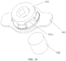
- the water outlet filter 34 may include a filter mounting frame 341 and the filter element 342.
- the filter mounting frame 341 is detachably mounted in the water outlet 321.
- a receiving hole through the filter mounting frame 341 is defined at the filter mounting frame 341.
- the filter element 342 is filled in the receiving hole.
- FIG 24 and 25 show the water outlet filter 34 using a such structure.
- the filter mounting frame 341 is mounted to the water outlet 321 of the lower cover 32, the amount of water can be regulated by the filter element 342. Since the filter mounting frame 341 is plugged into the water outlet 321 from the outside of the lower cover 32 (the side remote from the upper cover 31), the water outlet filter 34 can be replaced without removing the accommodating case body, so the replacement is more convenient. While the control of the amount of water only need to select the different permeability of the filter element 342, the water control is more accurate and good, thus ensuring the cleaning effect.
- a plurality of water inlets 341a are defined on the filter mounting frame 341.
- the water inlet 341a communicates with the receiving hole and the liquid accommodating room.
- the water inlets 341a are defined on the filter mounting frame 341.
- the water inlets 341a are spaced apart from each other in the circumferential direction of the filter mounting frame 341.
- the water outlet filter 34 may include only the filter element 342, as long as the amount of water can be regulated.
- the number of the water outlet filter 34 is two or more. Each water outlet filter 34 corresponds to a water outlet 321.
- the number of the water outlet filter 34 may be appropriately selected depending on the zone of the cleaning cloth 4 and the required humidity. More preferably, the water outlet filter 34 is two, and the distance between the two is 10 mm to 350 mm to ensure uniform wetting of the cleaning cloth 4. More preferably, the distance between the two water control filters is 80mm to 90mm.
- the water outlet filter 34 may include a stop gasket 343.
- the stop gasket 343 is provided on one end of the filter mounting frame 341. A recess is formed at the container case and formed around the water outlet 321. The stop gasket 343 is located in the recess.
- the water outlet filter 34 may further include the stop gasket 343 (which may be made of a rubber material).
- the stop gasket 343 is fixed to one end of the filter mounting frame 341 far away from the upper cover 31.
- a side of the lower cover 32, far away from the upper cover 31, defines a recess for receiving the stop gasket 343.
- the stop gasket 343 can preventing the liquid from flowing out of the gap between the water outlet and the water outlet filter 34, and on the other hand, an operation position can be provided for easily removing the water outlet filter 34.
- the water outlet filter 34 is used to control the amount of water discharged, making the replacement more convenient. And according to the needs in different environments, the filter element 342 with different materials make the amount of water discharged be controllable, and user-friendly choice.
- the liquid container includes an obstacle-assisting wheel 322.
- the obstacle-assisting wheel 322 is rotatable mounted on the container case.
- the obstacle-assisting wheel 322 protrudes from the surface of the container case.
- the effect of the obstacle-assisting wheel 322 will be described in connection with autonomous cleaning robot to which it is applied.
- the autonomous cleaning robot includes a main body 1 and a cleaning assembly.
- the main body 1 is configured to carry other structures.
- the cleaning assembly is mounted on the main body 1.
- the cleaning assembly include a first cleaning subassembly 2 which is detachably mounted on the main body 1. When the first cleaning subassembly 2 is loaded or removed from the main body 1, the first cleaning subassembly 2 moves in the forward direction or the backward direction of the main body 1.
- the first cleaning subassembly 2 may include a liquid container 3 mentioned above.
- the first cleaning subassembly 2 When the first cleaning subassembly 2 is mounted on the main body 1 or is removed from the main body 1, the first cleaning subassembly 2 is moved in the forward direction (or the backward direction) of the main body 1, so that the loading and removal of the first cleaning subassembly 2 is more convenient, and the problem that the bottom of the robot always needs to be turned upside down to install or disassemble the water tank therefrom can be solved.
- the forward direction of the main body 1 is in the horizontal direction, so that the loading and removal of the first cleaning subassembly 2 is more convenient.
- the liquid container 3 having the above-described structure makes it more effective to deliver water, thereby ensuring a cleaning effect.
- the autonomous cleaning robot may be, but is not limited to, a smart sweeping robot, a solar panel robot or a building exterior cleaning robot.
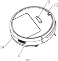
- a smart sweeping robot As shown in FIG 1 and 2 , the autonomous cleaning robot may be, but is not limited to, a smart sweeping robot, a solar panel robot or a building exterior cleaning robot.
- the embodiments of the invention will be described with reference to a smart sweeping robot.
- the autonomous cleaning robot may include a sensing system, a control system (not shown), an energy system and a human-computer interaction system 9, in addition to the main body 1 and the cleaning assembly.
- the autonomous includes a drive system. The main parts of the autonomous cleaning robot will be described in detail below.
- the main body 1 may include an upper cover, a forward part 13, a backward part 14, a chassis 11, and the like.
- the main body 1 has an approximately cylindrical configuration with minimal height (both front and rear are circular shape).
- the main body 1 may have other shapes, including but not limited to an approximately D-shaped shape with a front square and a rear circle.
- the sensing system includes a position determining device located above the main body 1, a buffer located at the forward part 13 of the main body 1, cliff sensor 51, ultrasonic sensor, infrared sensor, magnetometer, accelerometer, gyroscope, odometer and other sensing devices. These sensing devices provide the control system with various location information and motion status information for the machine.
- the position determining device includes, but is not limited to, an infrared transmitting and receiving device, a camera, a laser distance measuring device (LDS).
- the cleaning assembly includes a dry-cleaning section and a wet-cleaning section.
- the wet cleaning section is the first cleaning subassembly 2.
- the wet-cleaning section is configured to wipe the surface (such as the ground) by the cleaning cloth 4 containing the cleaning solution.
- the dry-cleaning section is the second cleaning subassembly.
- the dry-cleaning section is configured to clean the fixed particle contaminants on the cleaned surface by cleaning brush and other structures.
- the main cleaning function of the dry-cleaning section is derived from the second cleaning section including a roller brush 61, the dust cartridge, the fan, the air outlet, and the connecting member between the four parts.
- the roller brush 61 has a certain interference with the ground, sweeps dusts on the floor and rolls it in front of the suction port between the roller brush 61 and the dust cartridge. And then the dusts are sucked into the dust cartridge by the suction gas generated by the fan and through the dust cartridge.
- the dust removal capacity of the sweeping machine can be characterized by the dust pick up efficiency (DPU)
- the DPU is influenced by the structure and material of the roller brush 61, influenced by the wind power utilization ratio of a duct formed by the suction port, the fan, the dust cartridge, the air outlet, and the connecting member therebetween, and influenced by the type and power of the fan.
- the improvement of dust removal capacity is more meaningful for cleaning robots with limited energy resources.
- the improvement of dust removal capacity directly and effectively reduces the energy requirements.
- the robot could clean the 80-square-meter ground previously in case of one charge, and now, the robot can evolve into cleaning 100 square meters or more in case of one charge. Reducing the number of charges makes the battery life greatly increase, and makes the frequency at which the user changes the battery increase.
- the dry-cleaning system may also include a side brush 62 having a rotating shaft.
- the rotary shaft is at an angle relative to the ground.
- the rotary shaft is configured to move the debris into the cleaning zone of the roller brush 61 of the second cleaning section.
- the first cleaning subassembly 2 may mainly include the abovementioned liquid container 3 and cleaning cloth 4 and the like.
- the liquid container 3 is a base for supporting other components of the first cleaning subassembly 2.
- the cleaning cloth 4 is removable provided on the liquid container 3. The liquid in the liquid container 3 flows to the cleaning cloth 4. The cleaning cloth 4 wipes the ground after the ground is cleaned by the roller brush and the like.
- the drive system is configured to drive the main body 1 and components mounted on the main body to move for automatic travel and cleaning.
- the drive system includes a driving wheel module 71.
- the drive system issues a drive command to manipulate the robot to travel across the ground.
- the drive command is based on distance information and angle information, such as x, y and ⁇ components.
- the driving wheel module 71 simultaneously controls the left wheel and the right wheel.
- the driving wheel module 71 includes a left driving wheel module and a right driving wheel module.
- the left driving wheel module and the right driving wheel module are opposed to each other along a lateral axis defined by the main body 1.
- the robot may include one or more driven wheels 72.
- the driven wheels include, but is not limited to, a caster. So that the robot can move more stably or stronger on the ground.
- the driving wheel module 71 may include a travel wheel, a drive motor and a control circuit for controlling the drive motor.
- the driving wheel module 71 may also be connected to a circuit for measuring the drive current and an odometer.
- the driving wheel module 71 is detachably connected to the main body 1 for easy disassembly and maintenance.
- the driving wheel may have an offset drop suspension system.
- the driving wheel is movably fastened, for example, rotatable attached, to the main body 1 and receives a spring offset that is biased downward and away from the main body 1.
- the spring offset allows the driving wheel to maintain contact and traction with the ground with a certain ground force.
- the robot's cleaning elements such as roller brush, etc. also contact the ground with a certain pressure.
- the forward part 13 of the main body 1 may carry a buffer.
- the buffer detects one or more events in the travel path of the robot via a sensor system, such as an infrared sensor.
- the robot may control the driving wheel module 71 to respond to an event, such as away from an obstacle, by events detected by the buffer, such as an obstacle, a wall.
- the control system is provided on the circuit board in the main body 1.
- the control system may include a temporary memory and a communication computing processor.
- the temporary memory may include a hard disk, a flash memory and a random-access memory.
- the communication computing processor may include a central processing unit and an application processor.
- the application processor can draw an instant map of the environment in which the robot is located, based on the obstacle information fed back by the laser distance measuring device and the positioning algorithm, such as SLAM.
- the distance information and velocity information fed back by the sensor such as the buffer, the cliff sensor 51, the ultrasonic sensor, the infrared sensor, the magnetometer, the accelerometer, the gyroscope, the odometer and so on, are used to determine the current working state of the sweeping machine.
- the working state of the sweeping machine may include crossing the threshold, walking on the carpet, at the cliff, above or below stuck, the dust cartridge full, picked up, etc.
- the application processor gives specific instructions for the next step for different situations.
- the robot is more in line with the requirements of the owner, and provides a better user experience.
- the control system can plan the most efficient cleaning path and cleaning method based on real-time map information drawn by SLAM, which greatly improves the cleaning efficiency of the robot.
- the energy system may include a rechargeable battery, such as a nickel-metal hydride battery and a lithium battery.
- the rechargeable battery can be coupled to a charging control circuit, a battery pack charging temperature detecting circuit and a battery under voltage monitoring circuit.
- the charging control circuit, the battery pack charging temperature detecting circuit and the battery under voltage monitoring circuit connected with the microcontroller control circuit.
- the host is charged by connecting to the charging pile provided on the side or the lower side of the host. If the exposed charging electrode is dusted, the plastic body around the electrode will melt and deform due to the accumulation of charge during the charging process, and even cause the electrode itself to be deformed and cannot continue to be charged normally.
- the human-computer interaction system 9 includes buttons on the host panel and buttons are configured to select the function for user.
- the human-computer interaction system may also include a display screen and/or a light, and/or a speaker, the display, the light and the speaker are configured to show the user the status of the machine or a function selection.
- the human-computer interaction system may also include a mobile client application. For the path navigation type cleaning equipment, the mobile client can show the user the map of the equipment located, as well as the location of the equipment, and can provide users with more rich and user-friendly features.
- the autonomous cleaning robot can travel on the ground by various combinations of movements of the following three mutually perpendicular axes defined by the main body 1: a front and rear axis X (i.e., the axis in the direction of the forward part 13 and the backward part 14 of the main body 1), a lateral axis Y (i.e., the axis perpendicular to the axis X and the same horizontal as the axis X) and a center vertical axis Z (axis perpendicular to axis X and axis of axis Y).
- a front and rear axis X i.e., the axis in the direction of the forward part 13 and the backward part 14 of the main body 1
- a lateral axis Y i.e., the axis perpendicular to the axis X and the same horizontal as the axis X
- a center vertical axis Z axis perpendicular to axis
- the forward direction of the front and rear axis X is defined as “forward”, and the backward direction of the front and rear axis X is defined as “backward”.
- the lateral axis Y extends along the axis defined by the center point of the driving wheel module 71 between the right wheel and the left wheel of the autonomous cleaning robot.
- the autonomous cleaning robot can rotate around the Y axis.
- the forward part of the autonomous cleaning robot When the forward part of the autonomous cleaning robot is tilted upward and the backward part is tilted downward, it is defined as “up”.
- the forward part of the robot When the forward part of the robot is tilted downward and the backward part is tilted upward, it is defined as “down”.
- the robot can rotate around the Z axis. In the forward direction of the robot, when the robot tilts to the right side of the X axis, it is defined as "right turn”, and when the robot tilts to the left side of the X axis, it is defined as "left turn”.
- the dust cartridge is mounted in a receiving chamber by means of buckle and handle.
- the buckle shrinks.
- the buckle extends to a recess of the receiving chamber.
- the first cleaning subassembly 2 is mounted on the main body 1 by a guiding member.
- the first cleaning subassembly 2 is movable up and down with respect to the main body 1. That is, a gap exists between the first cleaning subassembly 2 and the main body 1.
- the first cleaning subassembly 2 is provided on the chassis 11 of the main body 1.
- the chassis 11 is provided with a protrusion structure 113 for mounting the first cleaning subassembly 2.
- the first cleaning subassembly 2 is provided on the chassis 11 at the backward part 14 of the main body 1.
- the first cleaning subassembly 2 is mounted to the chassis 11 through a guiding member, and the first cleaning subassembly 2 is in clearance fit with the chassis 11.
- the guiding member may include a first guiding ridge 311 and a first guiding groove 111.
- the first guiding groove 111 is defined on one of the first cleaning subassembly 2 and the chassis 11.
- the first guiding ridge 311 is provided on the other of the first cleaning subassembly 2 and the chassis 11.
- the first guiding groove 111 is defined on the side wall of the protrusion structure 113 of the chassis 11.
- the first guiding ridge 311 is provided on the liquid container 3 of the first cleaning subassembly 2.
- the first guiding ridge 311 plugs into the first guiding groove 111 to realize the guiding and stop action.
- the liquid container 3 defines a recess.
- the thickness of the first guiding ridge 311 is smaller than the width of the first guiding groove 111.
- the width of the first guiding groove 111 refers to the width between the opposite side walls of the first guiding groove 111, i.e., the vertical distance between the two opposite side walls when the robot is in the horizontal position.
- the width of the gap between the liquid container 3 and the chassis 11 can be determined as desired.
- the width of the gap between the liquid container 3 and the chassis 11 is in the range of 1.5 mm to 4 mm.
- the gap between the liquid container 3 and the chassis 11 is 2 mm. The gap provides a space for the insertion action when the user plugs the liquid container 3 into the chassis 11 without overturning the robot. The user can smoothly mount the liquid container 3 to the chassis 11 not required to strictly align the liquid container 3 with the chassis 11.
- the current mopping robot usually needs to be overturned (i.e., bottom up) by the user, and then the tank can be installed, on the one hand, the user is inconvenient to use and install, on the other hand, if the tank leaks, the water easily leaks into the interior of the robot, causing the robot to damage.
- the first cleaning subassembly 2 is mounted to the main body 1 in the forward direction or the backward direction of the main body 1 and then connected to the main body 1 through a connecting member.
- the connecting member may include a first connecting member provided on the main body 1 and a second connecting member provided on the first cleaning subassembly 2.
- autonomous cleaning robot may further include a connection control assembly.
- the connection control assembly is connected to the first connecting member or the second connecting member and control the connection and separation of the second connecting member and the first connecting member.
- connection control assembly is provided on the first cleaning subassembly 2.
- the connecting member is a buckle structure.
- the liquid container 3 is connected to the chassis 11 through the buckle structure.
- the buckle structure is not only easy to be installed, but also reliable.
- the connecting member may be other structures, such as a magnetic structure.
- the liquid container 3 may be connected to the chassis 11 by other means, such as magnetic connection.
- the connection control assembly may be a catching control system or a magnetic control system, to ensure that users can easily install and remove.
- the chassis 11 is provided with a first connecting member.
- the first connecting member may be a first buckle 112 or an electromagnet or a magnetic conductor and so on.
- the first buckle 112 is configured to couple with the liquid container 3 to realize the fixing of the liquid container 3.
- the liquid container 3 is provided with the second connecting member.
- the connecting member may be a second buckle 331 cooperated with the first buckle 112 or an electromagnet or a magnetic conductor.
- the first buckle 112 and the second buckle 331 cooperatively constitute the connecting member.
- the second buckle 331 defines a stop position and an avoiding position. As shown in FIG.
- the second buckle 331 and the first buckle 112 are stopped from each other, and the liquid container 3 is connected to the chassis 11.
- the second buckle 331 is separated from the first buckle 112, and the liquid container 3 can be detached from the chassis 11.
- connection control assembly may include an engagement control member 33.
- the engagement control member 33 controls the position of the second buckle 331, to make the second buckle engaged with or separated from the first buckle 112.
- the user can control the engagement control member 33 to control the position of the second buckle 331. That is, the liquid container 3 and the chassis 11 may be engaged or separated, to facilitate the loading or removal of the liquid container 3.
- an upper cover 31 of the liquid container 3 defines a recess for mounting the engagement control member 33 and the second buckle 331.
- the engagement control member 33 is provided in the upper cover 31.
- the upper cover 31 defines an opening for the first connecting member inserting thereinto and first connecting member cooperating with the second connecting member.
- the liquid container 3 includes the container case, the upper cover 31, and a lower cover 32.
- the container case defines a liquid accommodating room.
- the liquid placed in the liquid container is water.
- the liquid container may contain any other cleaning solution as required.
- one of the engagement control assemblies may include a mounting frame 332, an operating member 333 and an elastic piece 334.
- the second buckle 331 is fixedly mounted on the mounting frame.
- the mounting frame is movably disposed within the container case, and can drive the second buckle 331 to the stop position or avoiding position.
- the operating member is mounted on the mounting frame, and is integrally formed with the mounting frame 332. When the user presses the operating member 333, the operating member 333 drives the mounting frame 332 and the second buckle 331 thereon to move together.
- the elastic piece 334 is provided between the operating member 333 and the container case of the liquid container 3 to ensure that the second buckle 331 can be back to the stop position after the pressing force is lost, thereby ensuring that the liquid container 3 can connect with the chassis 11 reliably.
- the elastic piece 334 may be a structure which can provide an elastic force, such as a spring, an elastic rubber or the like. A first end of the elastic piece 334 abuts against the operating member 333 or the mounting frame 332. The second end of the elastic piece 334 abuts against the container case. And the direction of expansion and contraction of the elastic piece coincides with the moving direction of the mounting frame. In the condition of no press, the elastic force of the elastic piece 334 causes the second buckle 331 to be held in the stop position.
- the user presses the operating member 333 to move the second buckle 331 to the avoiding position, the first buckle 112 and the second buckle 331 on the chassis 11 are separated from the stopper, and then the liquid container 3 can be successfully removed.
- a stop protrusion 313 is provided on the container case of the liquid container.
- the mounting frame 332 defines a hole for the protrusion extending in.
- the stroke of the mounting frame 332 can be defined by fitting the stopper projection 313 and the hole wall 332a of the hole.
- the mounting frame 332 can be limited, the mounting member 332 can be released from the liquid container 3 without the pressing force due to the elastic force of the elastic piece 334.
- the first end of the elastic piece 334 abuts against the operating member 333.
- the second end of the elastic piece abuts against the stop protrusion 313.
- the operating member 333 and the stop protrusion 313 are provided with a cross-convex post for mounting the elastic piece 334.
- the liquid container 3 is plugged into the rear portion of the chassis 11 along the first guiding groove 111 on the chassis 11 to form an overall appearance of the autonomous cleaning robot.
- the chassis 11 of the robot has a first connecting portion.
- the first connecting may be a hook.
- the hook can connect with a second connection portion of the liquid container.
- the second connection portion may be a buckle. So that the liquid container can be fixed to the bottom of the main body 1.
- the first guiding groove 111 may be a U-shaped groove, and can be slid with the first guiding ridge 311 on the liquid container to guide the liquid container 3 to slide on the chassis 11.
- the second buckle 331 is in the recess of the liquid container 3.
- the first buckle 112 (hook) on the chassis 11 abuts against the second buckle 331 so that the second buckle 331 moves toward a region other than the recess.
- the first buckle 112 (hook) can slide into the recess along the slope on the second buckle 331 when the force is applied to a certain extent. Then the second buckle 331 is engaged with the first buckle 112 (hook) so that the liquid container 3 is fixed on the chassis 11.
- the operating member 333 of the engagement control member 33 can be pressed with overcoming the spring resistance.
- the second buckle 331 may be retracted in the liquid container 3 by the force transmission. Then the engagement between the first buckle 112 (hook) and the second buckle 331 may disappear, and the liquid container can be pulled out from the backward direction of main body 1 to realize the unloading of the liquid container 3.
- the engagement control member includes a connecting rod 381, a spring 382, a toggle piece 383, and a buckle 384.
- the buckle 384 is configured to cooperate with the first buckle 112 to connect the connection of the liquid container 3 and the chassis 11.
- the connecting rod 381 is provided in the liquid container 3.
- the first end of the connecting rod 381 is provided with the buckle 384, and the second end of the connecting rod 381 is provided with the toggle piece 383.
- the toggle piece 383 is rotatable provided in the liquid container 3.
- a first end of the toggle piece 383 is connected with the spring 382, a second end of the toggle piece 383 is an operating end for operating.
- the spring 382 is connected between the toggle piece 383 and the liquid container 3.
- the schematic view of the engagement control member is shown in FIG .19 .
- the upper cover 31 of the liquid container 3 is further provided with a water injection port 35 for injecting liquid into the liquid accommodating room.
- the water injection port 35 is provided with a water injection plug and a water injection cap to seal the water injection port 35.
- the lower cover 32 of the liquid container 3 is also provided with a water outlet 321, the water outlet 321 communicates with the liquid accommodating room, and the outlet 321 is removable provided with a water outlet filter 34 for controlling the amount of water.
- the lower cover 32 cooperates with the upper cover 31 to form the container case and surrounds the liquid accommodating room for accommodating the liquid.
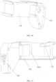
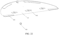
- the lower cover is configured to mount the cleaning cloth 4.
- a plurality of adhesive structures 324 are fixed to one side of the lower cover 32 remoting from the upper cover 31.
- the cleaning cloth 4 is laid on the side of the lower cover 32 far away from the upper cover 31 and is attached to the lower cover 32 by the adhesive structure.
- the adhesive structure 324 may be a double-sided adhesive or a Velcro. In order to facilitate the replacement of the cleaning cloth 4, preferably, the adhesive structure 324 is a Velcro.
- the edge of the cleaning cloth 4 is fixed, to ensure that the direction and position of the cleaning cloth 4 are correct, and the cleaning cloth 4 is prevented from being tilted and affecting the cleaning effect.
- the installation direction of the edge may not be limited and the correct installation of the cleaning cloth 4 cannot be guaranteed.
- the cleaning cloth 4 is provided with a first guide portion, and the liquid container 3 is provided with a second guide portion, and the first guide portion and the second guide portion can be engaged with each other. So that the cleaning cloth 4 is mounted on the liquid container 3.
- the first guide portion may be a guiding groove
- the second guide portion may be a guide rod that engages with the guiding groove.
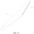
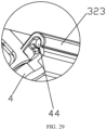
- a guiding strip 44 is fixedly provided on the side of the cleaning cloth 4 and a mounting groove 323 is provided in the liquid container 3.
- the guiding strip 44 penetrates into the mounting groove 323 and defines the side of the cleaning cloth 4 on the liquid container 3.
- the guiding strip 44 may be a plastic rod or a steel rod having a certain rigidity, or may be a flexible strip.
- the cross-sectional shape of the guiding strip 44 may be circular or other non-circular shape.
- the cross-sectional shape of the mounting groove 323 on the liquid container 3 is a C-shape or a shape like the C-shape, just make sure that the guiding strip 44 can be accommodated and defined.
- the opening (i.e., the opening of the C-shape) of the mounting groove 323 for the cleaning cloth 4 extending is directed downward.
- One end of the mounting groove 323 is an extending end (the end has no stop structure, which extends into the guiding strip 44) and the other end is a stop end (the end has a stop structure to prevent the guiding strip 44 from coming out of the end).
- one end of the mounting groove 323 is closed and the other end is open.
- the tail portion of the cleaning cloth 4 is fixed to the liquid container 3 by the guiding strip 44 and the mounting groove 323 to improve the fixing stability and prevent the cleaning cloth 4 from falling off.
- the guiding strip 44 and the mounting groove 323 are located in the liquid container 3 and in the direction of the forward. If the guiding strip 44 is mounted firstly and then the cleaning cloth 4 is adhered to the Velcro, the cleaning cloth can be installed correctly.
- the cleaning cloth 4 may be a cleaning cloth made of the same material, or a composite cleaning cloth with different parts thereof made of different materials.
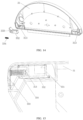
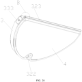
- the cleaning cloth is a composite cleaning cloth.
- the main body of the cleaning cloth is substantially semicircular.
- An inner layer 43 of the cleaning cloth is a water seepage zone with high permeability material.
- a middle layer 42 of the cleaning cloth is a decontamination zone with a harder material, and used to scrape off the harder material on the ground.
- An outer layer 41 of the cleaning cloth is a water absorption zone with better water absorption material, used to absorb the water on the bottom surface and remove the water stains. So the cleaning efficiency is improved.
- the guiding strip 44 is provided on a semicircular straight-line segment.
- the liquid in the liquid accommodating space flows out of the water outlet 321 on the lower cover 32 and wets the cleaning cloth 4.
- a barrier-assisting structure is provided on the bottom of the liquid container 3.
- the obstacle-assisting structure can assist the driving wheel module 71 of the autonomous cleaning robot when the autonomous cleaning robot is climbing or stepping, and provide support for the autonomous cleaning robot in the liquid container 3 to enhance the climbing and obstacle-surmounting capability thereof.
- the obstacle-assisting structure is an obstacle-assisting wheel for crossing obstacles.
- the obstacle-assisting wheel 322 is rotatable mounted on the liquid container 3.
- the lower cover 32 of the liquid container 3 is provided with the obstacle-assisting wheel 322, and the obstacle-assisting wheel 322 is rotatable mounted on the lower cover 32.
- the liquid container 3 is located at the end in the backward direction of the liquid container 3.
- the cleaning cloth 4 defines an opening at the position corresponding to the obstacle-assisting wheel 322 to avoid the obstacle-assisting wheel 322, so that the obstacle-assisting wheel 322 can be contacted with the ground when necessary.
- the cleaning cloth is provided with a notch, so that the obstacle-assisting wheel 322 can be in contact with the ground.
- the obstacle-assisting wheel 322 is not in contact with the ground (i.e., when the main body is in the horizontal state, the lowest point of the obstacle-assisting wheel provided on the liquid container is higher than the lowest point of the driving wheel).
- the autonomous cleaning robot is tilted on the slope or climbing step, the obstacle-assisting wheel 322 is contact with the ground to form a sliding support point to prevent the main body 1 from being jammed and achieve obstacle crossing.
- the height of the climbing step of the autonomous cleaning robot can be determined as needed, such as a height of the climbing step is 17 mm, or 19 mm, or higher.
- the connection mode between the liquid container and the main body is the buckle and groove connection.
- the liquid container is provided with a mounting and connecting structure that can horizontally loading the liquid container into the main body, do not turn the main body upside down.
- the liquid container can be directly plugged into the chassis of the autonomous cleaning robot horizontally, which greatly facilitate the user to install and disassemble.
- the connection mode between the liquid container and the main body is the clearance fit.
- the clearance fit between the liquid container and the main body is convenient for the user to install the liquid container and the main body. If the gap is too small, the liquid container can be inserted only when the gap is precise alignment, which will cause inconvenience for users. If the gap is large enough, the liquid container can be loaded even if the liquid container is inserted with a certain angle.
- the clearance fit between the liquid container and the main body can improve the robot's ability to obstruct and prevent stuck when encountering obstacles. When the autonomous cleaning robot encounters an obstacle, the liquid container can move up or down to cross the obstacle.
- the bottom of the liquid container is provided with the obstacle-assisting wheel.
- the obstacle-assisting wheel protrudes from the cleaning cloth.
- the obstacle-assisting wheel contacts the ground when crossing the obstacle. Because the liquid container is in clearance fit with the main body and provided with the obstacle-assisting wheel, the ability to cross the obstacle has greatly improved.
- the middle of the liquid container is recessed. Both sides of the liquid container may serve as a water storage department, but also as an installation department, killing two birds with one stone.
- the autonomous cleaning robot regulates the rate by way of the water control filter, instead of the water seepage cloth.
- the water control filter is more convenient to replace, and the rate can be adjusted.
- the obstacle-assisting wheel is mounted on the liquid container directly, so that the ability to cross the obstacle of the autonomous cleaning robot has improved.
Landscapes
- Engineering & Computer Science (AREA)
- Mechanical Engineering (AREA)
- Electric Vacuum Cleaner (AREA)
- Cleaning By Liquid Or Steam (AREA)
- Cleaning In General (AREA)
- Cleaning Implements For Floors, Carpets, Furniture, Walls, And The Like (AREA)
- Manipulator (AREA)
- Optical Head (AREA)
- Nozzles For Electric Vacuum Cleaners (AREA)
Description
- The invention relates to a cleaning equipment, and more particularly, to a liquid container and autonomous cleaning robot. The invention is set out in the appended set of claims.
- With the development of technology, a variety of autonomous cleaning robots have been appeared. For example, automatic sweeping robots, automatic mopping robots and so on. Autonomous cleaning robot can automatically and user-friendly perform cleaning operations. Taking the automatic sweeping robot as an example, the automatic sweeping robot can automatic clear an aria by scraping and vacuum cleaning technology. The scraping operation can be achieved by automatically cleaning the bottom of the device with a scraper and a roller brush.
- For an autonomous cleaning robot with a mopping function, it is often need to set up a water tank on the robot to provide the water source required for the mopping. Normally, the water tank is connected to the robot at a bottom thereof. The bottom of the robot always needs to be turned upside down to install or disassemble the water tank therefrom. It is likely to cause collision or damage of the top of the robot, and easy to damage the sensor installed on the top of the robot, resulting in greater economic losses. In addition, if the water tank has a leak, when the water tank is installed or disassembled, the leakage of water may flow into the robot through a gap of the bottom, resulting in damage to internal circuits and components and irreparable problems.
-
US2575675A1 discloses a foam maker, including a portable container for a liquid rug cleaning preparation, said container embodying, top, bottom, side and end walls, all of said walls being flat and substantially free of external projections, one end wall being provided, adjacent said bottom wall, with an opening, the other end wall being provided with foam discharging means, baffle means mounted in said container, a one-piece through said opening and wholly into the container, a horizontal top branch exteriorly overlying the top wall of the container and spaced therefrom and having a downturned terminal portion connected to and closed by said top wall, said horizontal branch constituting a carrying handle, and an intermediate vertical branch outwardly of and paralleling and contacting the adjacent end wall, said vertical branch having an outwardly projecting complemental neck, the latter serving as a liquid filler neck on the one hand and an air hose attaching neck on the other hand, said top branch being provided with an air relief port, and manually regulable valve means mounted on said top branch for opening and closing said port. -
CN201814516U discloses a rinsing robot, including a frame, a housing, a power supply system, a driving system, an automatic rinsing system, a water circulating system, a sensor system and an intelligent control system, the power supply system, the driving system, the automatic rinsing system, the water circulating system, the sensor system and the intelligent control system are mounted on the frame or mounted between the frame and the housing; the automatic rinsing system includes a sponge roller with a sponge sleeve, a motor and a squeezing roller which is driven by a motor to rotate and used for squeezing the sponge roller; the water circulating system includes a water pump, a water tank, a water trough, a sedimentation chamber, a magnetic valve and a water pipe for connecting the water pump, the water tank, the water trough, the sedimentation chamber and the magnetic valve; the sensor system includes a ground detecting device used for detecting the ground and a wall detecting device used for detecting sidewalls; and the intelligent control system controls the rinsing robot to conduct corresponding actions according to the feedback of other systems. -
CN106175613A discloses a household floor scrubber which includes a machine body. The machine body includes a sweeping mechanism for sweeping a target area in a floor, a water diversion mechanism for leading washing water to the target area, a cleaning mechanism for cleaning the target area with the washing water and a water suction mechanism for sucking dirty water which is left after the target area is cleaned; the sweeping mechanism is located at the front end of the machine body, the water suction mechanism is located at the rear end of the machine body, the water diversion mechanism and the cleaning mechanism are located in the middle of the machine body, the water diversion mechanism is arranged to be close to the sweeping mechanism, and the cleaning mechanism is located between the water diversion mechanism and the water suction mechanism. -
CN101647681A discloses a household muting floor-mopping robot including a vehicle body, a driving mechanism, a mop loading and conveying mechanism, a humidifying mechanism, an elevating mechanism, a control system and the like, the driving mechanism includes a driving motor, a left driving wheel and a right driving wheel; the control system includes a single chip microcomputer, a range measurement sensor, an infrared remote control module and the like; the mop loading and conveying mechanism includes a plurality of synchronous belt wheels installed at the front end of the vehicle body, a plurality of connecting rods for connecting the belt wheels, a DC geared motor for driving the connecting rods, rollers for providing positive pressure for the mop, and a synchronous belt installed on the synchronous belt wheels and the rollers; the humidifying mechanism includes a water tank, an electromagnet for controlling the water injection of the water tank, a lever and a water outlet screen; the elevating mechanism is installed on the tail of the vehicle body; and a universal wheel is installed on the bottom of the elevating mechanism. -
CN204813712U discloses a wet rag clean robot including a removable rag board, and it combines a rear side below with robot organism and accepts water supply, the rag board below has a wet rag, the rag board include: a cask, a capillary supply part for flowing the water stored in the cask forward in a capillary manner, and a water supply part for supplying water from the capillary supply part to the wet rag; and in the platelike rag board plate body, the capillary supply part is formed between the upper plate and the lower plate. - Embodiments of the invention provide a liquid container and an autonomous cleaning robot, to solve the problem of the rate of the water tank not working well and with improved ability to cross obstacles. The invention is set out in the appended set of claims.
- The liquid container of the embodiment of the invention can regulate the rate of the liquid container by setting the water outlet filter on the water outlet of the container case. The liquid container adopts the water outlet filter and uses the filter structure to regulate the rate to solve problems of the prior art. Compared with a water seepage cloth arranged in the water tank, with one end arranged in the water storage space and the other end arranged at the outlet, guiding the water in the water tank to the outlet through capillary action, using the filter structure to control the water discharged can solve the problem of the water flow rate not easy to control of the water seepage cloth. The water seepage cloth needs to be completely set in the container case body, so the replacement of the water seepage cloth is inconvenient and the cost is high, and the water tank is required to be disassembled. The water outlet filter of the liquid container of the embodiment of the invention set in the water outlet and is easy to be disassembled.
-
-
FIG. 1 illustrates a schematic view of a first view of an autonomous cleaning robot, in accordance with embodiments of the invention. -
FIG. 2 illustrates a schematic view of a second view of an autonomous cleaning robot, in accordance with embodiments of the invention. -
FIG. 3 illustrates a schematic view of a first view of a main body three-dimensional structure of a first perspective view of a main body and a first cleaning subassembly of an autonomous cleaning robot, in accordance with embodiments of the invention. -
FIG. 4 illustrates a schematic view of a second view of a main body and a first cleaning subassembly of an autonomous cleaning robot, in accordance with embodiments of the invention. -
FIG. 5 illustrates a schematic view of a third view of a main body and a first cleaning subassembly of an autonomous cleaning robot, in accordance with embodiments of the invention. -
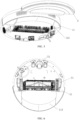
FIG. 6 illustrates a bottom view of a main body of an autonomous cleaning robot, in accordance with embodiments of the invention. -
FIG. 7 illustrates a bottom schematic view of a main body of an autonomous cleaning robot, in accordance with embodiments of the invention. -
FIG. 8 illustrates a bottom view of a chassis of a main body of an autonomous cleaning robot, in accordance with embodiments of the invention. -
FIG. 9 is a partial enlarged view of A inFIG. 8 . -
FIG. 10 illustrates a side view of a first guiding groove one the chassis of the main body of an autonomous cleaning robot, in accordance with embodiments of the invention. -
FIG. 11 illustrates a schematic view of a first view of a first view of a liquid container of an autonomous cleaning robot, in accordance with embodiments of the invention. -
FIG. 12 illustrates a schematic view of a second view of a liquid container of the autonomous cleaning robot, in accordance with embodiments of the invention. -
FIG. 13 illustrates a schematic view of a first view of an upper cover and an engagement control subassembly of a liquid container of an autonomous cleaning robot, in accordance with embodiments of the invention. -
FIG. 14 illustrates an explosion view of a second view of an upper cover and an engagement control subassembly of a liquid container of an autonomous cleaning robot, in accordance with embodiments of the invention. -
FIG. 15 illustrates a schematic view of the upper cover and the engagement control subassembly fit of a liquid container of an autonomous cleaning robot, in accordance with embodiments of the invention. -
FIG. 16 illustrates a schematic view of a first view of a mounting frame of an engagement control subassembly of an autonomous cleaning robot, in accordance with embodiments of the invention. -
FIG. 17 illustrates a schematic view of a second view of a mounting frame of an engagement control subassembly of an autonomous cleaning robot, in accordance with embodiments of the invention. -
FIG. 18 illustrates a schematic view of the structure of the engagement control member, the first buckle and the second buckle fit of the autonomous cleaning robot, in accordance with embodiments of the invention. -
FIG. 19 illustrates a schematic view of another engagement control subassembly of an autonomous cleaning robot, in accordance with embodiments of the invention. -
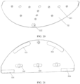
FIG. 20 illustrates a schematic view of a first view of a lower cover of a liquid container of an autonomous cleaning robot, in accordance with embodiments of the invention. -
FIG. 21 illustrates a schematic view of a second view of a lower cover of a liquid container of an autonomous cleaning robot, in accordance with embodiments of the invention. -
FIG. 22 illustrates a schematic view of a third view of a lower cover of a liquid container of an autonomous cleaning robot, in accordance with embodiments of the invention. -
FIG. 23 illustrates a schematic view of a liquid container of an autonomous cleaning robot, in accordance with embodiments of the invention. -
FIG. 24 illustrates a schematic view of a first view of a water outlet filter of an autonomous cleaning robot, in accordance with embodiments of the invention. -
FIG. 25 illustrates a schematic view of a second view of a water outlet filter of an autonomous cleaning robot, in accordance with embodiments of the invention. -
FIG. 26 illustrates a schematic view of a cleaning cloth of an autonomous cleaning robot, in accordance with embodiments of the invention. -
FIG. 27 illustrates a schematic view of a cleaning cloth of an autonomous cleaning robot, in accordance with embodiments of the invention. -
FIG. 28 illustrates a schematic view of a liquid container and a cleaning cloth fit of an autonomous cleaning robot, in accordance with embodiments of the invention. -
FIG. 29 is a partial enlarged view of B inFIG.28 . - List of reference numerals:
main body 1;chassis 11; the first guidinggroove 111; thefirst buckle 112;protrusion structure 113;forward part 13; backwardpart 14; thefirst cleaning subassembly 2;liquid container 3;upper cover 31; the first guidingridge 311; opening 312;stop protrusion 313;lower cover 32;water outlet 321; the obstacle-assistingwheel 322;mounting groove 323;adhesive structure 324;engagement control member 33; thesecond buckle 331;mounting frame 332;hole wall 332a;operating member 333;elastic piece 334; water outlet filter 34;filter mounting frame 341;water inlet 341a;filter element 342;stop gasket 343;water injection port 35; connectingrod 381;spring 382;toggle piece 383;buckle 384;cleaning cloth 4;outer layer 41;middle layer 42;inner layer 43; guidingstrip 44;cliff sensor 51;roller brush 61;side brush 62;driving wheel module 71; drivenwheel 72; human-computer interaction system 9. - As the following, the liquid container and the intelligent cleaning apparatus of the embodiment of the present invention will be described in detail with attached drawings.
- Use of the terminology "forward" refers to primary direction of motion of the autonomous cleaning robot.
- Use of the terminology "backward" refers to opposite direction of primary direction of motion of the autonomous cleaning robot.
- According to embodiments of the invention, the present embodiment provides an autonomous cleaning robot, the autonomous cleaning robot includes a liquid container. The liquid container includes a container case. A
water outlet 321 is defined at the container case. Thewater outlet 321 communicates with the liquid accommodating room in the container case. A water outlet filter 34 is defined on thewater outlet 321. The water outlet filter 34 is configured to regulate the rate of the water outlet. The filter structure of the water outlet filter 34 is used to achieve effluence control by means of setting the water outlet filter 34 on the water outlet. The liquid container adopts the water outlet filter and uses the filter structure to regulate the rate to solve problems of the prior art. Compared with a water seepage cloth arranged in the water tank, with one end arranged in the water storage space and the other end arranged at the outlet, guiding the water in the water tank to the outlet through capillary action, using the filter structure to control the water discharged can solve the problem of the water flow rate not easy to control of the water seepage cloth. The water seepage cloth needs to be completely set in the container case body, so the replacement of the water seepage cloth is inconvenient and the cost is high, and the water tank is required to be disassembled. The filter structure is removable provided in theoutlet 321 for easier replacement. - In the present embodiments, the water seepage cloth in the liquid container is omitted. Only using the water outlet filter 34 to control the effluence, the water control can be better.
- In the present embodiments, the liquid container is used in the autonomous cleaning robot, such as a sweeping robot. The liquid container is configured to hold the cleaning fluid (e.g., water) of the autonomous cleaning robot. Of course, in other embodiments, the liquid container can also be used in other suitable environments.
- Optionally, the container case may include an
upper cover 31 and alower cover 32. Theupper cover 31 is connected to thelower cover 32. Thewater outlet 321 is provided on thelower cover 32. - Optionally, there are a plurality of
water outlets 321. The plurality ofwater outlet 321 is provided on the container case spaced from each other. According to different needs of the amount of water, the number of thewater outlets 321 can be different. Twowater outlets 321 can ensure the amount of water and avoid frequent water needs caused by water flowing too fast. Of cause, it is also possible to control the amount of water of thesingle water outlet 321 by adjusting the size of thewater outlet 321. - Optionally, the water outlet filter 34 may include a
filter element 342. Thefilter element 342 is plugged into thewater outlet 321, and blocks thewater outlet 321. The liquid in the liquid container must pass through thefilter element 342 to flow out. By controlling the permeation rate of thefilter element 342, it is possible to regulate the rate and to solve the problem of the water flow rate not easy to control of the water seepage cloth. - Optionally, the water outlet filter 34 may include a
filter mounting frame 341 and thefilter element 342. Thefilter mounting frame 341 is detachably mounted in thewater outlet 321. A receiving hole through thefilter mounting frame 341 is defined at thefilter mounting frame 341. Thefilter element 342 is filled in the receiving hole.FIG 24 and25 show the water outlet filter 34 using a such structure. After thefilter mounting frame 341 is mounted to thewater outlet 321 of thelower cover 32, the amount of water can be regulated by thefilter element 342. Since thefilter mounting frame 341 is plugged into thewater outlet 321 from the outside of the lower cover 32 (the side remote from the upper cover 31), the water outlet filter 34 can be replaced without removing the accommodating case body, so the replacement is more convenient. While the control of the amount of water only need to select the different permeability of thefilter element 342, the water control is more accurate and good, thus ensuring the cleaning effect. - In order to facilitate the water inside the container case flow into the
filter element 342, a plurality ofwater inlets 341a are defined on thefilter mounting frame 341. Thewater inlet 341a communicates with the receiving hole and the liquid accommodating room. Optionally, thewater inlets 341a are defined on thefilter mounting frame 341. Thewater inlets 341a are spaced apart from each other in the circumferential direction of thefilter mounting frame 341. - Certainly, in other embodiments, the water outlet filter 34 may include only the
filter element 342, as long as the amount of water can be regulated. - Optionally, the number of the water outlet filter 34 is two or more. Each water outlet filter 34 corresponds to a
water outlet 321. The number of the water outlet filter 34 may be appropriately selected depending on the zone of the cleaningcloth 4 and the required humidity. More preferably, the water outlet filter 34 is two, and the distance between the two is 10 mm to 350 mm to ensure uniform wetting of the cleaningcloth 4. More preferably, the distance between the two water control filters is 80mm to 90mm. The water outlet filter 34 may include astop gasket 343. Thestop gasket 343 is provided on one end of thefilter mounting frame 341. A recess is formed at the container case and formed around thewater outlet 321. Thestop gasket 343 is located in the recess. Optionally, the water outlet filter 34 may further include the stop gasket 343 (which may be made of a rubber material). Thestop gasket 343 is fixed to one end of thefilter mounting frame 341 far away from theupper cover 31. A side of thelower cover 32, far away from theupper cover 31, defines a recess for receiving thestop gasket 343. On the one hand, thestop gasket 343 can preventing the liquid from flowing out of the gap between the water outlet and the water outlet filter 34, and on the other hand, an operation position can be provided for easily removing the water outlet filter 34. The water outlet filter 34 is used to control the amount of water discharged, making the replacement more convenient. And according to the needs in different environments, thefilter element 342 with different materials make the amount of water discharged be controllable, and user-friendly choice. - In order to improve the climbing and obstructing ability of the autonomous cleaning robot, enable the autonomous cleaning robot adapt to more different using environments, the liquid container includes an obstacle-assisting
wheel 322. The obstacle-assistingwheel 322 is rotatable mounted on the container case. The obstacle-assistingwheel 322 protrudes from the surface of the container case. For ease of understanding, the effect of the obstacle-assistingwheel 322 will be described in connection with autonomous cleaning robot to which it is applied. - The autonomous cleaning robot includes a
main body 1 and a cleaning assembly. Themain body 1 is configured to carry other structures. The cleaning assembly is mounted on themain body 1. The cleaning assembly include afirst cleaning subassembly 2 which is detachably mounted on themain body 1. When thefirst cleaning subassembly 2 is loaded or removed from themain body 1, thefirst cleaning subassembly 2 moves in the forward direction or the backward direction of themain body 1. Thefirst cleaning subassembly 2 may include aliquid container 3 mentioned above. When thefirst cleaning subassembly 2 is mounted on themain body 1 or is removed from themain body 1, thefirst cleaning subassembly 2 is moved in the forward direction (or the backward direction) of themain body 1, so that the loading and removal of thefirst cleaning subassembly 2 is more convenient, and the problem that the bottom of the robot always needs to be turned upside down to install or disassemble the water tank therefrom can be solved. Normally, the forward direction of themain body 1 is in the horizontal direction, so that the loading and removal of thefirst cleaning subassembly 2 is more convenient. Theliquid container 3 having the above-described structure makes it more effective to deliver water, thereby ensuring a cleaning effect. - As shown in
FIG 1 and2 , the autonomous cleaning robot may be, but is not limited to, a smart sweeping robot, a solar panel robot or a building exterior cleaning robot. The embodiments of the invention will be described with reference to a smart sweeping robot. - The autonomous cleaning robot may include a sensing system, a control system (not shown), an energy system and a human-
computer interaction system 9, in addition to themain body 1 and the cleaning assembly. The autonomous includes a drive system. The main parts of the autonomous cleaning robot will be described in detail below. - The
main body 1 may include an upper cover, aforward part 13, abackward part 14, achassis 11, and the like. Themain body 1 has an approximately cylindrical configuration with minimal height (both front and rear are circular shape). Themain body 1 may have other shapes, including but not limited to an approximately D-shaped shape with a front square and a rear circle. - The sensing system includes a position determining device located above the
main body 1, a buffer located at theforward part 13 of themain body 1,cliff sensor 51, ultrasonic sensor, infrared sensor, magnetometer, accelerometer, gyroscope, odometer and other sensing devices. These sensing devices provide the control system with various location information and motion status information for the machine. The position determining device includes, but is not limited to, an infrared transmitting and receiving device, a camera, a laser distance measuring device (LDS). - The cleaning assembly includes a dry-cleaning section and a wet-cleaning section. Wherein, the wet cleaning section is the
first cleaning subassembly 2. The wet-cleaning section is configured to wipe the surface (such as the ground) by the cleaningcloth 4 containing the cleaning solution. The dry-cleaning section is the second cleaning subassembly. The dry-cleaning section is configured to clean the fixed particle contaminants on the cleaned surface by cleaning brush and other structures. - The main cleaning function of the dry-cleaning section is derived from the second cleaning section including a
roller brush 61, the dust cartridge, the fan, the air outlet, and the connecting member between the four parts. - The
roller brush 61 has a certain interference with the ground, sweeps dusts on the floor and rolls it in front of the suction port between theroller brush 61 and the dust cartridge. And then the dusts are sucked into the dust cartridge by the suction gas generated by the fan and through the dust cartridge. The dust removal capacity of the sweeping machine can be characterized by the dust pick up efficiency (DPU) - The DPU is influenced by the structure and material of the
roller brush 61, influenced by the wind power utilization ratio of a duct formed by the suction port, the fan, the dust cartridge, the air outlet, and the connecting member therebetween, and influenced by the type and power of the fan. Compared to ordinary plug-in vacuum cleaner, the improvement of dust removal capacity is more meaningful for cleaning robots with limited energy resources. The improvement of dust removal capacity directly and effectively reduces the energy requirements. In other words, the robot could clean the 80-square-meter ground previously in case of one charge, and now, the robot can evolve into cleaning 100 square meters or more in case of one charge. Reducing the number of charges makes the battery life greatly increase, and makes the frequency at which the user changes the battery increase. More intuitive and important, the improvement of dust removal capacity is the most obvious and important user experience. The user will directly find out whether the cleaning and wiping are clean or not. The dry-cleaning system may also include aside brush 62 having a rotating shaft. The rotary shaft is at an angle relative to the ground. The rotary shaft is configured to move the debris into the cleaning zone of theroller brush 61 of the second cleaning section. - As the wet-cleaning subassembly, the
first cleaning subassembly 2 may mainly include the abovementionedliquid container 3 and cleaningcloth 4 and the like. Theliquid container 3 is a base for supporting other components of thefirst cleaning subassembly 2. The cleaningcloth 4 is removable provided on theliquid container 3. The liquid in theliquid container 3 flows to thecleaning cloth 4. The cleaningcloth 4 wipes the ground after the ground is cleaned by the roller brush and the like. - The drive system is configured to drive the
main body 1 and components mounted on the main body to move for automatic travel and cleaning. The drive system includes adriving wheel module 71. The drive system issues a drive command to manipulate the robot to travel across the ground. The drive command is based on distance information and angle information, such as x, y and θ components. Thedriving wheel module 71 simultaneously controls the left wheel and the right wheel. In order to control the movement of the machine, Optionally thedriving wheel module 71 includes a left driving wheel module and a right driving wheel module. The left driving wheel module and the right driving wheel module are opposed to each other along a lateral axis defined by themain body 1. The robot may include one or more drivenwheels 72. The driven wheels include, but is not limited to, a caster. So that the robot can move more stably or stronger on the ground. - The
driving wheel module 71 may include a travel wheel, a drive motor and a control circuit for controlling the drive motor. Thedriving wheel module 71 may also be connected to a circuit for measuring the drive current and an odometer. Thedriving wheel module 71 is detachably connected to themain body 1 for easy disassembly and maintenance. The driving wheel may have an offset drop suspension system. The driving wheel is movably fastened, for example, rotatable attached, to themain body 1 and receives a spring offset that is biased downward and away from themain body 1. The spring offset allows the driving wheel to maintain contact and traction with the ground with a certain ground force. At the same time the robot's cleaning elements (such as roller brush, etc.) also contact the ground with a certain pressure. - The
forward part 13 of themain body 1 may carry a buffer. When thedriving wheel module 71 drives the robot to travel on the ground during cleaning, the buffer detects one or more events in the travel path of the robot via a sensor system, such as an infrared sensor. The robot may control thedriving wheel module 71 to respond to an event, such as away from an obstacle, by events detected by the buffer, such as an obstacle, a wall. - The control system is provided on the circuit board in the
main body 1. The control system may include a temporary memory and a communication computing processor. The temporary memory may include a hard disk, a flash memory and a random-access memory. The communication computing processor may include a central processing unit and an application processor. The application processor can draw an instant map of the environment in which the robot is located, based on the obstacle information fed back by the laser distance measuring device and the positioning algorithm, such as SLAM. The distance information and velocity information fed back by the sensor, such as the buffer, thecliff sensor 51, the ultrasonic sensor, the infrared sensor, the magnetometer, the accelerometer, the gyroscope, the odometer and so on, are used to determine the current working state of the sweeping machine. The working state of the sweeping machine may include crossing the threshold, walking on the carpet, at the cliff, above or below stuck, the dust cartridge full, picked up, etc. The application processor gives specific instructions for the next step for different situations. The robot is more in line with the requirements of the owner, and provides a better user experience. Furthermore, the control system can plan the most efficient cleaning path and cleaning method based on real-time map information drawn by SLAM, which greatly improves the cleaning efficiency of the robot. - The energy system may include a rechargeable battery, such as a nickel-metal hydride battery and a lithium battery. The rechargeable battery can be coupled to a charging control circuit, a battery pack charging temperature detecting circuit and a battery under voltage monitoring circuit. The charging control circuit, the battery pack charging temperature detecting circuit and the battery under voltage monitoring circuit connected with the microcontroller control circuit. The host is charged by connecting to the charging pile provided on the side or the lower side of the host. If the exposed charging electrode is dusted, the plastic body around the electrode will melt and deform due to the accumulation of charge during the charging process, and even cause the electrode itself to be deformed and cannot continue to be charged normally.
- The human-
computer interaction system 9 includes buttons on the host panel and buttons are configured to select the function for user. The human-computer interaction system may also include a display screen and/or a light, and/or a speaker, the display, the light and the speaker are configured to show the user the status of the machine or a function selection. The human-computer interaction system may also include a mobile client application. For the path navigation type cleaning equipment, the mobile client can show the user the map of the equipment located, as well as the location of the equipment, and can provide users with more rich and user-friendly features. - In order to describe the behavior of the autonomous cleaning robot more clearly, directions are defined as follows. The autonomous cleaning robot can travel on the ground by various combinations of movements of the following three mutually perpendicular axes defined by the main body 1: a front and rear axis X (i.e., the axis in the direction of the
forward part 13 and thebackward part 14 of the main body 1), a lateral axis Y (i.e., the axis perpendicular to the axis X and the same horizontal as the axis X) and a center vertical axis Z (axis perpendicular to axis X and axis of axis Y). The forward direction of the front and rear axis X is defined as "forward", and the backward direction of the front and rear axis X is defined as "backward". The lateral axis Y extends along the axis defined by the center point of thedriving wheel module 71 between the right wheel and the left wheel of the autonomous cleaning robot. - The autonomous cleaning robot can rotate around the Y axis. When the forward part of the autonomous cleaning robot is tilted upward and the backward part is tilted downward, it is defined as "up". When the forward part of the robot is tilted downward and the backward part is tilted upward, it is defined as "down". In addition, the robot can rotate around the Z axis. In the forward direction of the robot, when the robot tilts to the right side of the X axis, it is defined as "right turn", and when the robot tilts to the left side of the X axis, it is defined as "left turn".
- The dust cartridge is mounted in a receiving chamber by means of buckle and handle. When the handle is pulled, the buckle shrinks. When the handle is released, the buckle extends to a recess of the receiving chamber.
- The specific structure of the
first cleaning subassembly 2 and themain body 1 will be described in detail below. - The
first cleaning subassembly 2 is mounted on themain body 1 by a guiding member. When thefirst cleaning subassembly 2 is mounted on themain body 1, thefirst cleaning subassembly 2 is movable up and down with respect to themain body 1. That is, a gap exists between thefirst cleaning subassembly 2 and themain body 1. - Specifically, the
first cleaning subassembly 2 is provided on thechassis 11 of themain body 1. Thechassis 11 is provided with aprotrusion structure 113 for mounting thefirst cleaning subassembly 2. In the embodiments, thefirst cleaning subassembly 2 is provided on thechassis 11 at thebackward part 14 of themain body 1. - The
first cleaning subassembly 2 is mounted to thechassis 11 through a guiding member, and thefirst cleaning subassembly 2 is in clearance fit with thechassis 11. - As shown in
FIG .3 to FIG .10 , the guiding member may include afirst guiding ridge 311 and afirst guiding groove 111. Thefirst guiding groove 111 is defined on one of thefirst cleaning subassembly 2 and thechassis 11. Thefirst guiding ridge 311 is provided on the other of thefirst cleaning subassembly 2 and thechassis 11. - In the illustrated embodiments, the
first guiding groove 111 is defined on the side wall of theprotrusion structure 113 of thechassis 11. Thefirst guiding ridge 311 is provided on theliquid container 3 of thefirst cleaning subassembly 2. When theliquid container 3 is engaged with thechassis 11, thefirst guiding ridge 311 plugs into thefirst guiding groove 111 to realize the guiding and stop action. As illustrated inFIG .11 , in order to make way of theprotrusion structure 113 on thechassis 11, theliquid container 3 defines a recess. - Optionally, in order to facilitate the installation of the
liquid container 3, the thickness of thefirst guiding ridge 311 is smaller than the width of thefirst guiding groove 111. Wherein, the width of thefirst guiding groove 111 refers to the width between the opposite side walls of thefirst guiding groove 111, i.e., the vertical distance between the two opposite side walls when the robot is in the horizontal position. After thefirst guiding ridge 311 is plugged into thefirst guiding groove 111, thefirst guiding ridge 311 has a distance between the opposite side walls of thefirst guiding groove 111. A clearance fit structure between theliquid container 3 and thechassis 11 is formed to facilitate the user to install theliquid container 3. - The width of the gap between the
liquid container 3 and thechassis 11 can be determined as desired. In the present embodiments, the width of the gap between theliquid container 3 and thechassis 11 is in the range of 1.5 mm to 4 mm. Optionally, the gap between theliquid container 3 and thechassis 11 is 2 mm. The gap provides a space for the insertion action when the user plugs theliquid container 3 into thechassis 11 without overturning the robot. The user can smoothly mount theliquid container 3 to thechassis 11 not required to strictly align theliquid container 3 with thechassis 11. The current mopping robot, usually needs to be overturned (i.e., bottom up) by the user, and then the tank can be installed, on the one hand, the user is inconvenient to use and install, on the other hand, if the tank leaks, the water easily leaks into the interior of the robot, causing the robot to damage. - In the present embodiment, the
first cleaning subassembly 2 is mounted to themain body 1 in the forward direction or the backward direction of themain body 1 and then connected to themain body 1 through a connecting member. The connecting member may include a first connecting member provided on themain body 1 and a second connecting member provided on thefirst cleaning subassembly 2. - Optionally, in order to facilitate control of the connection and separation of the
first cleaning subassembly 2 from themain body 1, autonomous cleaning robot may further include a connection control assembly. The connection control assembly is connected to the first connecting member or the second connecting member and control the connection and separation of the second connecting member and the first connecting member. - Preferably, the connection control assembly is provided on the
first cleaning subassembly 2. - In the embodiments, the connecting member is a buckle structure. The
liquid container 3 is connected to thechassis 11 through the buckle structure. The buckle structure is not only easy to be installed, but also reliable. Of course, in other embodiments, the connecting member may be other structures, such as a magnetic structure. Theliquid container 3 may be connected to thechassis 11 by other means, such as magnetic connection. Correspondingly, the connection control assembly may be a catching control system or a magnetic control system, to ensure that users can easily install and remove. - The details will be described in detail with respect to the specific embodiment in which the
liquid container 3 and thechassis 11 are connected by a buckle structure. - Referring to
FIG .7 , thechassis 11 is provided with a first connecting member. The first connecting member may be afirst buckle 112 or an electromagnet or a magnetic conductor and so on. Taking the first buckle as an example, thefirst buckle 112 is configured to couple with theliquid container 3 to realize the fixing of theliquid container 3. Referring toFIG .11 to FIG .17 , theliquid container 3 is provided with the second connecting member. The connecting member may be asecond buckle 331 cooperated with thefirst buckle 112 or an electromagnet or a magnetic conductor. Thefirst buckle 112 and thesecond buckle 331 cooperatively constitute the connecting member. Thesecond buckle 331 defines a stop position and an avoiding position. As shown inFIG. 18 , at the stop position, thesecond buckle 331 and thefirst buckle 112 are stopped from each other, and theliquid container 3 is connected to thechassis 11. At the avoiding position, thesecond buckle 331 is separated from thefirst buckle 112, and theliquid container 3 can be detached from thechassis 11. - In order to control the engagement and separation of the first buckle and the
second buckle 331, the connection control assembly may include anengagement control member 33. Theengagement control member 33 controls the position of thesecond buckle 331, to make the second buckle engaged with or separated from thefirst buckle 112. In used, the user can control theengagement control member 33 to control the position of thesecond buckle 331. That is, theliquid container 3 and thechassis 11 may be engaged or separated, to facilitate the loading or removal of theliquid container 3. - Specifically, an
upper cover 31 of theliquid container 3 defines a recess for mounting theengagement control member 33 and thesecond buckle 331. Theengagement control member 33 is provided in theupper cover 31. Theupper cover 31 defines an opening for the first connecting member inserting thereinto and first connecting member cooperating with the second connecting member. - The
liquid container 3 includes the container case, theupper cover 31, and alower cover 32. The container case defines a liquid accommodating room. In the embodiments, the liquid placed in the liquid container is water. Of course, in other embodiments, the liquid container may contain any other cleaning solution as required. - As illustrated in
FIG .14 to FIG .17 , one of the engagement control assemblies may include a mountingframe 332, an operatingmember 333 and anelastic piece 334. - The
second buckle 331 is fixedly mounted on the mounting frame. The mounting frame is movably disposed within the container case, and can drive thesecond buckle 331 to the stop position or avoiding position. The operating member is mounted on the mounting frame, and is integrally formed with the mountingframe 332. When the user presses the operatingmember 333, the operatingmember 333 drives the mountingframe 332 and thesecond buckle 331 thereon to move together. - The
elastic piece 334 is provided between the operatingmember 333 and the container case of theliquid container 3 to ensure that thesecond buckle 331 can be back to the stop position after the pressing force is lost, thereby ensuring that theliquid container 3 can connect with thechassis 11 reliably. Theelastic piece 334 may be a structure which can provide an elastic force, such as a spring, an elastic rubber or the like. A first end of theelastic piece 334 abuts against the operatingmember 333 or the mountingframe 332. The second end of theelastic piece 334 abuts against the container case. And the direction of expansion and contraction of the elastic piece coincides with the moving direction of the mounting frame. In the condition of no press, the elastic force of theelastic piece 334 causes thesecond buckle 331 to be held in the stop position. When the user needs to remove theliquid container 3, the user presses the operatingmember 333 to move thesecond buckle 331 to the avoiding position, thefirst buckle 112 and thesecond buckle 331 on thechassis 11 are separated from the stopper, and then theliquid container 3 can be successfully removed. - As illustrated in
FIG .13 , astop protrusion 313 is provided on the container case of the liquid container. The mountingframe 332 defines a hole for the protrusion extending in. The stroke of the mountingframe 332 can be defined by fitting thestopper projection 313 and thehole wall 332a of the hole. Thus, the mountingframe 332 can be limited, the mountingmember 332 can be released from theliquid container 3 without the pressing force due to the elastic force of theelastic piece 334. - In the embodiments, the first end of the
elastic piece 334 abuts against the operatingmember 333. The second end of the elastic piece abuts against thestop protrusion 313. The operatingmember 333 and thestop protrusion 313 are provided with a cross-convex post for mounting theelastic piece 334. - The specific process of loading the
liquid container 3 into thechassis 11 is as follows: - As illustrated in
FIG .3 and FIG .4 , theliquid container 3 is plugged into the rear portion of thechassis 11 along thefirst guiding groove 111 on thechassis 11 to form an overall appearance of the autonomous cleaning robot. Thechassis 11 of the robot has a first connecting portion. In some specific embodiments, the first connecting may be a hook. The hook can connect with a second connection portion of the liquid container. In some specific embodiments, the second connection portion may be a buckle. So that the liquid container can be fixed to the bottom of themain body 1. Thefirst guiding groove 111 may be a U-shaped groove, and can be slid with thefirst guiding ridge 311 on the liquid container to guide theliquid container 3 to slide on thechassis 11. - In the natural state, the
second buckle 331 is in the recess of theliquid container 3. When theliquid container 3 is slid into the mating position along thefirst guiding groove 111 on thechassis 11, the first buckle 112 (hook) on thechassis 11 abuts against thesecond buckle 331 so that thesecond buckle 331 moves toward a region other than the recess. The first buckle 112 (hook) can slide into the recess along the slope on thesecond buckle 331 when the force is applied to a certain extent. Then thesecond buckle 331 is engaged with the first buckle 112 (hook) so that theliquid container 3 is fixed on thechassis 11. After theliquid container 3 being mounted on thechassis 11, when the fix needs to be released, the operatingmember 333 of theengagement control member 33 can be pressed with overcoming the spring resistance. Thesecond buckle 331 may be retracted in theliquid container 3 by the force transmission. Then the engagement between the first buckle 112 (hook) and thesecond buckle 331 may disappear, and the liquid container can be pulled out from the backward direction ofmain body 1 to realize the unloading of theliquid container 3. - In another engagement control member (not shown), the engagement control member includes a connecting
rod 381, aspring 382, atoggle piece 383, and abuckle 384. Thebuckle 384 is configured to cooperate with thefirst buckle 112 to connect the connection of theliquid container 3 and thechassis 11. The connectingrod 381 is provided in theliquid container 3. The first end of the connectingrod 381 is provided with thebuckle 384, and the second end of the connectingrod 381 is provided with thetoggle piece 383. Thetoggle piece 383 is rotatable provided in theliquid container 3. A first end of thetoggle piece 383 is connected with thespring 382, a second end of thetoggle piece 383 is an operating end for operating. Thespring 382 is connected between thetoggle piece 383 and theliquid container 3. The schematic view of the engagement control member is shown inFIG .19 . - As shown in
FIG .20 to FIG .23 , theupper cover 31 of theliquid container 3 is further provided with awater injection port 35 for injecting liquid into the liquid accommodating room. Thewater injection port 35 is provided with a water injection plug and a water injection cap to seal thewater injection port 35. - The
lower cover 32 of theliquid container 3 is also provided with awater outlet 321, thewater outlet 321 communicates with the liquid accommodating room, and theoutlet 321 is removable provided with a water outlet filter 34 for controlling the amount of water. - On the one hand, the
lower cover 32 cooperates with theupper cover 31 to form the container case and surrounds the liquid accommodating room for accommodating the liquid. On the other hand, the lower cover is configured to mount thecleaning cloth 4. A plurality ofadhesive structures 324 are fixed to one side of thelower cover 32 remoting from theupper cover 31. The cleaningcloth 4 is laid on the side of thelower cover 32 far away from theupper cover 31 and is attached to thelower cover 32 by the adhesive structure. Theadhesive structure 324 may be a double-sided adhesive or a Velcro. In order to facilitate the replacement of the cleaningcloth 4, preferably, theadhesive structure 324 is a Velcro. - As shown in
FIG .27 to FIG .29 , more preferably, the edge of the cleaningcloth 4 is fixed, to ensure that the direction and position of the cleaningcloth 4 are correct, and thecleaning cloth 4 is prevented from being tilted and affecting the cleaning effect. If using a paste method to fix thecleaning cloth 4, the installation direction of the edge may not be limited and the correct installation of the cleaningcloth 4 cannot be guaranteed. For example, if the cleaning cloth is slant relative to the tank, the cleaning effect will be seriously affected. Therefore, the cleaningcloth 4 is provided with a first guide portion, and theliquid container 3 is provided with a second guide portion, and the first guide portion and the second guide portion can be engaged with each other. So that the cleaningcloth 4 is mounted on theliquid container 3. The first guide portion may be a guiding groove, and the second guide portion may be a guide rod that engages with the guiding groove. - Specifically, a guiding
strip 44 is fixedly provided on the side of the cleaningcloth 4 and a mountinggroove 323 is provided in theliquid container 3. The guidingstrip 44 penetrates into the mountinggroove 323 and defines the side of the cleaningcloth 4 on theliquid container 3. - The guiding
strip 44 may be a plastic rod or a steel rod having a certain rigidity, or may be a flexible strip. The cross-sectional shape of the guidingstrip 44 may be circular or other non-circular shape. The cross-sectional shape of the mountinggroove 323 on theliquid container 3 is a C-shape or a shape like the C-shape, just make sure that the guidingstrip 44 can be accommodated and defined. The opening (i.e., the opening of the C-shape) of the mountinggroove 323 for thecleaning cloth 4 extending is directed downward. One end of the mountinggroove 323 is an extending end (the end has no stop structure, which extends into the guiding strip 44) and the other end is a stop end (the end has a stop structure to prevent the guidingstrip 44 from coming out of the end). In other words, one end of the mountinggroove 323 is closed and the other end is open. The tail portion of the cleaningcloth 4 is fixed to theliquid container 3 by the guidingstrip 44 and the mountinggroove 323 to improve the fixing stability and prevent thecleaning cloth 4 from falling off. The guidingstrip 44 and the mountinggroove 323 are located in theliquid container 3 and in the direction of the forward. If the guidingstrip 44 is mounted firstly and then thecleaning cloth 4 is adhered to the Velcro, the cleaning cloth can be installed correctly. - As illustrated in
FIG .26 , the cleaningcloth 4 may be a cleaning cloth made of the same material, or a composite cleaning cloth with different parts thereof made of different materials. In the embodiments, the cleaning cloth is a composite cleaning cloth. The main body of the cleaning cloth is substantially semicircular. Aninner layer 43 of the cleaning cloth is a water seepage zone with high permeability material. Amiddle layer 42 of the cleaning cloth is a decontamination zone with a harder material, and used to scrape off the harder material on the ground. Anouter layer 41 of the cleaning cloth is a water absorption zone with better water absorption material, used to absorb the water on the bottom surface and remove the water stains. So the cleaning efficiency is improved. The guidingstrip 44 is provided on a semicircular straight-line segment. - The liquid in the liquid accommodating space flows out of the
water outlet 321 on thelower cover 32 and wets the cleaningcloth 4. By selecting a filter structure with different material, the amount of the water discharged can be controlled, and the needs of users can be better met. - A barrier-assisting structure is provided on the bottom of the
liquid container 3. The obstacle-assisting structure can assist thedriving wheel module 71 of the autonomous cleaning robot when the autonomous cleaning robot is climbing or stepping, and provide support for the autonomous cleaning robot in theliquid container 3 to enhance the climbing and obstacle-surmounting capability thereof. - The obstacle-assisting structure is an obstacle-assisting wheel for crossing obstacles. The obstacle-assisting
wheel 322 is rotatable mounted on theliquid container 3. Specifically, thelower cover 32 of theliquid container 3 is provided with the obstacle-assistingwheel 322, and the obstacle-assistingwheel 322 is rotatable mounted on thelower cover 32. Theliquid container 3 is located at the end in the backward direction of theliquid container 3. The cleaningcloth 4 defines an opening at the position corresponding to the obstacle-assistingwheel 322 to avoid the obstacle-assistingwheel 322, so that the obstacle-assistingwheel 322 can be contacted with the ground when necessary. - Correspondingly, the cleaning cloth is provided with a notch, so that the obstacle-assisting
wheel 322 can be in contact with the ground. When the autonomous cleaning robot is moved on a horizontal ground, the obstacle-assistingwheel 322 is not in contact with the ground (i.e., when the main body is in the horizontal state, the lowest point of the obstacle-assisting wheel provided on the liquid container is higher than the lowest point of the driving wheel). When the autonomous cleaning robot is tilted on the slope or climbing step, the obstacle-assistingwheel 322 is contact with the ground to form a sliding support point to prevent themain body 1 from being jammed and achieve obstacle crossing. The height of the climbing step of the autonomous cleaning robot can be determined as needed, such as a height of the climbing step is 17 mm, or 19 mm, or higher. - The autonomous cleaning robot of the invention has the following effects:
- The connection mode between the liquid container and the main body is the buckle and groove connection. The liquid container is provided with a mounting and connecting structure that can horizontally loading the liquid container into the main body, do not turn the main body upside down. The liquid container can be directly plugged into the chassis of the autonomous cleaning robot horizontally, which greatly facilitate the user to install and disassemble.
- The connection mode between the liquid container and the main body is the clearance fit. On one hand, the clearance fit between the liquid container and the main body is convenient for the user to install the liquid container and the main body. If the gap is too small, the liquid container can be inserted only when the gap is precise alignment, which will cause inconvenience for users. If the gap is large enough, the liquid container can be loaded even if the liquid container is inserted with a certain angle. On the other hand, the clearance fit between the liquid container and the main body can improve the robot's ability to obstruct and prevent stuck when encountering obstacles. When the autonomous cleaning robot encounters an obstacle, the liquid container can move up or down to cross the obstacle.
- The bottom of the liquid container is provided with the obstacle-assisting wheel. The obstacle-assisting wheel protrudes from the cleaning cloth. The obstacle-assisting wheel contacts the ground when crossing the obstacle. Because the liquid container is in clearance fit with the main body and provided with the obstacle-assisting wheel, the ability to cross the obstacle has greatly improved.
- The middle of the liquid container is recessed. Both sides of the liquid container may serve as a water storage department, but also as an installation department, killing two birds with one stone.
- The autonomous cleaning robot regulates the rate by way of the water control filter, instead of the water seepage cloth. The water control filter is more convenient to replace, and the rate can be adjusted.
- The obstacle-assisting wheel is mounted on the liquid container directly, so that the ability to cross the obstacle of the autonomous cleaning robot has improved.
Claims (5)
- An autonomous cleaning robot comprising:a main body (1);a cleaning assembly mounted on the main body (1); wherein the cleaning assembly comprises a first cleaning subassembly (2) detachably mounted on the main body (1), when the first cleaning subassembly (2) is loaded or removed from the main body (1), the first cleaning subassembly (2) moves in the forward direction or the backward direction of the main body (1);wherein the first cleaning subassembly (2) comprises a liquid container (3) comprising: a container case and a water outlet filter (34), wherein the container case defines a water outlet (321) thereon and a liquid accommodating room therein, the water outlet (321) communicates with the liquid accommodating room, the water outlet filter (34) is mounted on the water outlet (321), and the water outlet filter (34) is configured to regulate the rate of the liquid dispensed from the liquid accommodating room;wherein an obstacle-assisting wheel (322) is located at a bottom end of the container case in a backward direction thereof;characterized in that the autonomous cleaning robot further comprises: a driving wheel module (71), the driving wheel module (71) comprising a driving wheel rotatable mounted on the main body (1), wherein when the main body (1) is in a horizontal state, a lowest point of the obstacle-assisting wheel (322) on the liquid container (3) is higher than a lowest point of the driving wheel.
- The autonomous cleaning robot of claim 1, wherein the first cleaning subassembly (2) further comprises a cleaning cloth (4), the cleaning cloth (4) is disposed on a side of the container case, the obstacle-assisting wheel (322) is mounted on the side of the container case, the cleaning cloth (4) defines an opening to expose the obstacle-assisting wheel (322) therefrom.
- The autonomous cleaning robot of claim 1, wherein the cleaning cloth (4) is detachably mounted on the liquid container (3), a first guide portion is provided on the cleaning cloth (4), a second guide portion is provided on the liquid container (3), the first guide portion and the second guide portion are engaged with each other to limit the installation direction of the cleaning cloth (4).
- The autonomous cleaning robot of claim 3, wherein the first guide portion comprises a guiding groove, the second guide portion comprises a guide bar engaged with the guiding groove, and the guide bar is configured to plug into the guiding groove to limit the movement of the cleaning cloth (4) relative to the liquid container (3).
- The autonomous cleaning robot of claim 3, wherein the first guide portion comprises a guiding strip (44), the second guide portion comprises a mounting groove (323), the guiding strip (44) is configured to plug and be fixed in the mounting groove (323) to limit the movement of the cleaning cloth (4) relative to the liquid container (3);
wherein preferably,the guiding strip (44) is fixed to the cleaning cloth (4) by a connecting member, the mounting groove (323) defines a notch therein to avoid the connecting member, a first end of the mounting groove (323) defines an opening thereon, the guiding strip (44) passes through the opening into the mounting groove, the second end of the mounting groove is provided with a stop structure to stop the guiding strip (44) escaping from the mounting groove;
and/orthe cleaning cloth (4) is semicircular, and the cleaning cloth (4) comprises a water seepage zone, a decontamination zone and a water absorption zone in turn.
Applications Claiming Priority (2)
| Application Number | Priority Date | Filing Date | Title |
|---|---|---|---|
| CN201710061574 | 2017-01-26 | ||
| PCT/CN2017/113998 WO2018137407A1 (en) | 2017-01-26 | 2017-11-30 | Liquid container and autonomous cleaning robot |
Publications (3)
| Publication Number | Publication Date |
|---|---|
| EP3487375A1 EP3487375A1 (en) | 2019-05-29 |
| EP3487375A4 EP3487375A4 (en) | 2020-09-02 |
| EP3487375B1 true EP3487375B1 (en) | 2023-09-20 |
Family
ID=62977840
Family Applications (4)
| Application Number | Title | Priority Date | Filing Date |
|---|---|---|---|
| EP21195129.8A Pending EP3942990A1 (en) | 2017-01-26 | 2017-11-30 | Liquid container and autonomous cleaning robot |
| EP17894513.5A Active EP3506811B1 (en) | 2017-01-26 | 2017-11-30 | Autonomous cleaning robot |
| EP17894024.3A Active EP3487375B1 (en) | 2017-01-26 | 2017-11-30 | Liquid container and autonomous cleaning robot |
| EP21195096.9A Pending EP3957223A1 (en) | 2017-01-26 | 2017-11-30 | Autonomous cleaning robot |
Family Applications Before (2)
| Application Number | Title | Priority Date | Filing Date |
|---|---|---|---|
| EP21195129.8A Pending EP3942990A1 (en) | 2017-01-26 | 2017-11-30 | Liquid container and autonomous cleaning robot |
| EP17894513.5A Active EP3506811B1 (en) | 2017-01-26 | 2017-11-30 | Autonomous cleaning robot |
Family Applications After (1)
| Application Number | Title | Priority Date | Filing Date |
|---|---|---|---|
| EP21195096.9A Pending EP3957223A1 (en) | 2017-01-26 | 2017-11-30 | Autonomous cleaning robot |
Country Status (7)
| Country | Link |
|---|---|
| US (5) | US11109730B2 (en) |
| EP (4) | EP3942990A1 (en) |
| JP (5) | JP6733883B2 (en) |
| KR (2) | KR102154454B1 (en) |
| CN (4) | CN208598297U (en) |
| ES (1) | ES2932600T3 (en) |
| WO (4) | WO2018137406A1 (en) |
Families Citing this family (48)
| Publication number | Priority date | Publication date | Assignee | Title |
|---|---|---|---|---|
| CN208598297U (en) * | 2017-01-26 | 2019-03-15 | 深圳洛克时代科技有限公司 | Intelligent cleaning equipment |
| KR101949278B1 (en) * | 2017-02-01 | 2019-02-18 | 엘지전자 주식회사 | Robot cleaner |
| US10595698B2 (en) * | 2017-06-02 | 2020-03-24 | Irobot Corporation | Cleaning pad for cleaning robot |
| JP2020036748A (en) * | 2018-09-04 | 2020-03-12 | 東芝ライフスタイル株式会社 | Vacuum cleaning device |
| CN109008825A (en) * | 2018-09-07 | 2018-12-18 | 深圳市沃特沃德股份有限公司 | Cleaning box and sweeping robot |
| CN109106290A (en) * | 2018-09-07 | 2019-01-01 | 深圳市沃特沃德股份有限公司 | Collecting box and sweeping robot |
| CN109124502A (en) * | 2018-09-07 | 2019-01-04 | 深圳市沃特沃德股份有限公司 | Header tank and sweeping robot |
| CN111685653B (en) * | 2019-03-12 | 2021-10-01 | 美智纵横科技有限责任公司 | Water tank for sweeper and sweeper with water tank |
| CN109222774A (en) * | 2018-10-15 | 2019-01-18 | 北京石头世纪科技有限公司 | Cleaning cloth mounting structure and intelligent cleaning equipment |
| CN109528098A (en) * | 2019-01-26 | 2019-03-29 | 东莞芯速科技有限公司 | A kind of mounting structure and clean robot of cleaning box |
| CN109567683A (en) * | 2019-01-31 | 2019-04-05 | 任飞 | A kind of intelligent sweeping robot |
| CN111904333A (en) * | 2019-05-08 | 2020-11-10 | 无锡睿米信息技术有限公司 | Water tank and cleaning device thereof |
| CN110172939A (en) * | 2019-05-22 | 2019-08-27 | 重庆北崎包装制品有限公司 | A kind of intelligent sweeping robot |
| CN214231225U (en) * | 2019-06-05 | 2021-09-21 | 尚科宁家运营有限公司 | Robot cleaner and cleaning pad for robot cleaner |
| CN110477811B (en) * | 2019-07-10 | 2022-02-15 | 深圳市伽利略机器人有限公司 | Install formula intelligence machine water tank annex of sweeping floor additional |
| KR102305206B1 (en) | 2019-07-11 | 2021-09-28 | 엘지전자 주식회사 | Robot cleaner for cleaning in consideration of floor state through artificial intelligence and operating method thereof |
| KR102286287B1 (en) * | 2019-07-31 | 2021-08-04 | 엘지전자 주식회사 | Robot Cleaner |
| KR102279788B1 (en) | 2019-07-31 | 2021-07-19 | 엘지전자 주식회사 | Robot Cleaner |
| KR102269273B1 (en) | 2019-07-31 | 2021-06-29 | 엘지전자 주식회사 | Robot Cleaner |
| CN110338713A (en) * | 2019-08-12 | 2019-10-18 | 侨银环保科技股份有限公司 | A kind of stair cleaning machine device people of solar energy |
| CN110353582B (en) * | 2019-08-15 | 2023-10-27 | 追觅创新科技(苏州)有限公司 | Down-pressing floor-mopping type floor-sweeping robot |
| TWD209976S (en) * | 2019-09-05 | 2021-02-21 | 大陸商北京石頭世紀科技股份有限公司 | Water tank |
| CN110448234A (en) * | 2019-09-05 | 2019-11-15 | 北京石头世纪科技股份有限公司 | Intelligent cleaning equipment |
| CN210931186U (en) * | 2019-09-05 | 2020-07-07 | 北京石头世纪科技股份有限公司 | Seal and block up and intelligent cleaning equipment |
| CN110537875A (en) * | 2019-09-05 | 2019-12-06 | 北京石头世纪科技股份有限公司 | Cleaning assembly and intelligent cleaning equipment |
| CN214104326U (en) * | 2019-09-29 | 2021-09-03 | 北京石头世纪科技股份有限公司 | Driving wheel module and self-moving robot |
| CN212698739U (en) * | 2019-10-12 | 2021-03-16 | 苏州宝时得电动工具有限公司 | Cleaning robot |
| CN110881904B (en) * | 2019-11-08 | 2021-07-30 | 华南理工大学广州学院 | Cleaning method of floor cleaning robot |
| CN110934545B (en) | 2019-11-29 | 2022-05-03 | 深圳市银星智能科技股份有限公司 | Cleaning robot |
| CN110881905A (en) * | 2019-11-29 | 2020-03-17 | 赵海荣 | Sweeping and mopping integrated robot and control method |
| JP2021097952A (en) * | 2019-12-24 | 2021-07-01 | 東芝ライフスタイル株式会社 | Vacuum cleaner |
| CN111135641B (en) * | 2020-01-06 | 2021-11-02 | 广东博智林机器人有限公司 | Filter core device of cleaning robot and cleaning robot |
| CN111436865A (en) * | 2020-03-09 | 2020-07-24 | 深圳市无限动力发展有限公司 | Cleaning robot and cleaning assembly mounting structure thereof |
| CN111772537B (en) * | 2020-07-14 | 2022-01-28 | 广东乐生智能科技有限公司 | Domestic intelligent anti-collision dust remover |
| CN113951773B (en) * | 2020-07-21 | 2023-01-24 | 深圳乐动机器人股份有限公司 | Cleaning robot working method and device and cleaning robot |
| USD1003550S1 (en) * | 2020-09-03 | 2023-10-31 | Sharkninja Operating Llc | Robot vacuum wet module |
| KR102476711B1 (en) * | 2020-12-23 | 2022-12-12 | 에브리봇 주식회사 | Robot Cleaner |
| CN112806916B (en) * | 2021-02-10 | 2022-11-04 | 北京石头世纪科技股份有限公司 | Automatic cleaning equipment |
| EP4292494A1 (en) * | 2021-02-10 | 2023-12-20 | Beijing Roborock Technology Co., Ltd. | Automatic cleaning device |
| USD999470S1 (en) * | 2021-02-10 | 2023-09-19 | Beijing Roborock Technology Co., Ltd. | Supporting plate for cleaning pad for robotic vacuum cleaner |
| TWD219026S (en) * | 2021-03-29 | 2022-05-21 | 大陸商北京小米移動軟件有限公司 | Cleaning robot |
| CN113261881B (en) * | 2021-05-31 | 2022-08-16 | 深圳市云视机器人有限公司 | Automatic battery replacement method |
| CN215305537U (en) * | 2021-07-05 | 2021-12-28 | 北京石头世纪科技股份有限公司 | Dust box and automatic cleaning equipment |
| CN115670294A (en) | 2021-07-22 | 2023-02-03 | 好样科技有限公司 | Self-moving cleaning device |
| CN114617483B (en) * | 2021-09-01 | 2023-06-30 | 北京石头世纪科技股份有限公司 | Key structure, liquid storage tank and automatic cleaning equipment |
| WO2023040526A1 (en) * | 2021-09-17 | 2023-03-23 | Yunjing Intelligence Technology (Dongguan) Co., Ltd. | Cleaning robot |
| ES2938277A1 (en) * | 2021-10-05 | 2023-04-05 | Cecotec Res And Development S L | SMART HEAD FOR ELECTRIC MOP (Machine-translation by Google Translate, not legally binding) |
| CN114103699B (en) * | 2021-12-29 | 2023-10-27 | 江西众一智慧科技有限公司 | Underground automatic recovery device for automobile charging pile power line and operation method of underground automatic recovery device |
Family Cites Families (70)
| Publication number | Priority date | Publication date | Assignee | Title |
|---|---|---|---|---|
| US2575675A (en) * | 1948-12-21 | 1951-11-20 | Marcil G Morgan | Foam maker for cleaners |
| JPH0436789Y2 (en) * | 1986-07-05 | 1992-08-31 | ||
| JPH0436958U (en) * | 1990-07-24 | 1992-03-27 | ||
| JPH08500493A (en) * | 1992-06-16 | 1996-01-23 | アーケン,ヤコブ,ウイルヘルムス | Improvement of wiper |
| JP3062680B2 (en) * | 1995-06-14 | 2000-07-12 | シャープ株式会社 | Electronic device with input pen |
| JP3627954B2 (en) * | 1997-09-26 | 2005-03-09 | 株式会社吉野工業所 | Cleaning tool |
| SE523080C2 (en) * | 1998-01-08 | 2004-03-23 | Electrolux Ab | Docking system for self-propelled work tools |
| US7571511B2 (en) | 2002-01-03 | 2009-08-11 | Irobot Corporation | Autonomous floor-cleaning robot |
| JP2004202149A (en) * | 2002-11-07 | 2004-07-22 | Masao Kosuge | Cleaner using melamine foam |
| JP2004337301A (en) * | 2003-05-14 | 2004-12-02 | Toshiba Tec Corp | Cleaning robot |
| WO2005077244A1 (en) * | 2004-02-04 | 2005-08-25 | S. C. Johnson & Son, Inc. | Surface treating device with cartridge-based cleaning system |
| CN101297267B (en) * | 2005-09-02 | 2012-01-11 | Neato机器人技术公司 | Multi-function robotic device |
| JP2007190258A (en) * | 2006-01-20 | 2007-08-02 | Funai Electric Co Ltd | Self-propelled vacuum cleaner |
| US8292536B2 (en) * | 2006-03-15 | 2012-10-23 | Ecolab Usa Inc. | Method and apparatus of applying a floor product solution |
| KR20070104989A (en) * | 2006-04-24 | 2007-10-30 | 삼성전자주식회사 | Robot cleaner system and method to eliminate dust thereof |
| KR200422221Y1 (en) * | 2006-05-04 | 2006-07-25 | 박정기 | A Wet Duster |
| WO2008017495A2 (en) * | 2006-08-10 | 2008-02-14 | Aquis Wasser-Luft-Systeme Gmbh, Lindau Zweigniederlassung Rebstein | Tank |
| JP2008061678A (en) | 2006-09-05 | 2008-03-21 | Funai Electric Co Ltd | Dust box unit of cleaner |
| KR100831619B1 (en) * | 2007-04-12 | 2008-05-26 | 주식회사 마미로봇 | Floor-cloth fixing structure |
| KR101001699B1 (en) * | 2008-07-17 | 2010-12-15 | 황인석 | Steam pushing pressure adjuster of steam cleaner |
| TW201023803A (en) * | 2008-12-25 | 2010-07-01 | Yan-Ping Chen | Improvement of filtering device of coffee-making device |
| KR101015465B1 (en) * | 2009-05-20 | 2011-02-22 | 서울과학기술대학교 산학협력단 | The robot cleaner with a small vaccum cleaner to fold |
| KR20100132891A (en) * | 2009-06-10 | 2010-12-20 | 삼성광주전자 주식회사 | A cleaning device and a dust collecting method thereof |
| JP5241644B2 (en) * | 2009-07-30 | 2013-07-17 | 富士フイルム株式会社 | Radiation image capturing apparatus and radiation image capturing method |
| CN101647681A (en) * | 2009-08-26 | 2010-02-17 | 哈尔滨工业大学(威海) | Household muting floor-mopping robot |
| KR20100006151A (en) * | 2009-12-04 | 2010-01-18 | 한종현 | Washing machine integrated mop cleaner |
| KR101138657B1 (en) * | 2010-06-21 | 2012-04-19 | (주)마미로봇 | Robot cleaner |
| JP2012029991A (en) * | 2010-08-02 | 2012-02-16 | Plus One Service:Kk | Cover member for squeegee channel |
| CN201814516U (en) * | 2010-09-15 | 2011-05-04 | 深圳市银星智能电器有限公司 | Rinsing robot |
| KR101230147B1 (en) * | 2010-10-25 | 2013-02-05 | 이재하 | Cleaning Robot for Wet Rag Sweeping |
| JP5739141B2 (en) * | 2010-11-30 | 2015-06-24 | 大王製紙株式会社 | Cleaning tool |
| US8741013B2 (en) * | 2010-12-30 | 2014-06-03 | Irobot Corporation | Dust bin for a robotic vacuum |
| CN201939277U (en) * | 2011-01-13 | 2011-08-24 | 深圳市银星智能电器有限公司 | Cleaning robot with garbage box convenient to disassemble |
| CN201936191U (en) * | 2011-01-26 | 2011-08-17 | 宋红丽 | Cleaning robot |
| KR101272212B1 (en) * | 2011-02-08 | 2013-06-11 | 최나래 | Rotation Stick Mop With Wheel |
| KR20120129192A (en) * | 2011-05-19 | 2012-11-28 | 어수곤 | robot cleaner |
| US8898844B1 (en) * | 2011-07-08 | 2014-12-02 | Irobot Corporation | Mopping assembly for a mobile robot |
| CN202445993U (en) | 2012-01-09 | 2012-09-26 | 成浩 | Air filtering cleaning robot |
| KR101352195B1 (en) * | 2012-03-08 | 2014-01-16 | 엘지전자 주식회사 | Robot cleaner |
| US9282867B2 (en) * | 2012-12-28 | 2016-03-15 | Irobot Corporation | Autonomous coverage robot |
| TWI508692B (en) * | 2013-02-08 | 2015-11-21 | Self-propelled trailing machine | |
| KR101520043B1 (en) * | 2013-07-24 | 2015-05-14 | 에브리봇 주식회사 | Wet cloth cleaning robot |
| CN103799924A (en) | 2014-01-28 | 2014-05-21 | 洛阳理工学院 | Automatic floor cleaning device for domestic use |
| TWM490676U (en) * | 2014-05-13 | 2014-11-21 | Advanced Connectek Inc | Card connector capable of fast ejecting card |
| CN204133376U (en) | 2014-08-01 | 2015-02-04 | 深圳市宝乐机器人技术有限公司 | A kind of Intelligent cleaning robot automatically cleaning is inhaled and is dragged integrated apparatus |
| KR20160025392A (en) * | 2014-08-27 | 2016-03-08 | 에브리봇 주식회사 | Suction nozzle, robot cleaner and control method thereof |
| CN104323740B (en) * | 2014-10-03 | 2016-09-07 | 张周新 | A kind of Wet-dry dust catcher |
| KR102266928B1 (en) * | 2014-12-02 | 2021-06-18 | 엘지전자 주식회사 | Mop module and robot cleaner having the same |
| US9788698B2 (en) * | 2014-12-10 | 2017-10-17 | Irobot Corporation | Debris evacuation for cleaning robots |
| US10292553B1 (en) * | 2014-12-16 | 2019-05-21 | Bobsweep Inc. | Mopping extension for a robotic vacuum |
| CN204379171U (en) * | 2014-12-31 | 2015-06-10 | 科沃斯机器人有限公司 | From mobile ground treating apparatus |
| CN105796015A (en) * | 2014-12-31 | 2016-07-27 | 科沃斯机器人有限公司 | Self-moving ground treating device |
| DE102015104247B4 (en) * | 2015-03-20 | 2022-05-12 | Miele & Cie. Kg | Self-propelled floor care device with a device for applying a floor care liquid |
| CN204600371U (en) * | 2015-04-14 | 2015-09-02 | 深圳市恒润晖光电科技有限公司 | Self-propelled mopping device |
| CN204698453U (en) | 2015-06-05 | 2015-10-14 | 东莞市宝联电子科技有限公司 | Dust-collecting box |
| CN204813712U (en) * | 2015-06-10 | 2015-12-02 | 玛纽尔科贸(北京)有限公司 | Wet rag clean robot |
| KR101634905B1 (en) | 2015-06-22 | 2016-06-29 | 엘지전자 주식회사 | Cleaner and water cleaning devce |
| KR101671116B1 (en) | 2015-07-09 | 2016-10-31 | 엘지전자 주식회사 | Cleaner and water cleaning devce |
| CN205018991U (en) * | 2015-09-25 | 2016-02-10 | 科沃斯机器人有限公司 | Rag, water tank and cleaning device thereof |
| CN205306905U (en) * | 2015-10-16 | 2016-06-15 | 东莞缔奇智能股份有限公司 | Floor cleaning robot |
| CN205181254U (en) * | 2015-11-04 | 2016-04-27 | 东莞市智科智能科技有限公司 | Cleaning robot |
| AU2016102017A4 (en) | 2015-12-04 | 2017-01-12 | Bissell Inc. | Cyclone module for vacuum cleaner |
| CN205458464U (en) * | 2015-12-31 | 2016-08-17 | 科沃斯机器人有限公司 | Water tank and cleaning machines people thereof |
| CN205458437U (en) * | 2016-01-04 | 2016-08-17 | 江苏美的清洁电器股份有限公司 | Scrubbing brush and dust catcher |
| CN205849399U (en) * | 2016-04-07 | 2017-01-04 | 杭州信多达电器有限公司 | A kind of cistern device of intelligent sweeping |
| CN205795618U (en) * | 2016-05-10 | 2016-12-14 | 深圳瑞科时尚电子有限公司 | A kind of cisten mechanism cleaning equipment |
| CN106108776B (en) * | 2016-08-04 | 2018-12-07 | 深圳瑞科时尚电子有限公司 | Interchangeable cistern assembly and household back-drawing dust catcher |
| CN106175613A (en) * | 2016-08-04 | 2016-12-07 | 深圳瑞科时尚电子有限公司 | Domestic floor-cleaning machine |
| CN206355004U (en) * | 2016-10-12 | 2017-07-28 | 深圳市智意科技有限公司 | Embed floating type radiator assembling structure and intelligent sweeping |
| CN208598297U (en) * | 2017-01-26 | 2019-03-15 | 深圳洛克时代科技有限公司 | Intelligent cleaning equipment |
-
2017
- 2017-09-29 CN CN201721276596.3U patent/CN208598297U/en active Active
- 2017-09-29 CN CN201721278070.9U patent/CN208582332U/en active Active
- 2017-10-12 CN CN201721318534.4U patent/CN208659179U/en active Active
- 2017-10-12 CN CN201721326291.9U patent/CN208659200U/en active Active
- 2017-11-30 KR KR1020197003026A patent/KR102154454B1/en active IP Right Grant
- 2017-11-30 WO PCT/CN2017/113979 patent/WO2018137406A1/en active Application Filing
- 2017-11-30 ES ES17894513T patent/ES2932600T3/en active Active
- 2017-11-30 EP EP21195129.8A patent/EP3942990A1/en active Pending
- 2017-11-30 JP JP2019510330A patent/JP6733883B2/en active Active
- 2017-11-30 KR KR1020197003223A patent/KR102154455B1/en active IP Right Grant
- 2017-11-30 JP JP2019510331A patent/JP7043487B2/en active Active
- 2017-11-30 WO PCT/CN2017/114012 patent/WO2018137408A1/en active Application Filing
- 2017-11-30 EP EP17894513.5A patent/EP3506811B1/en active Active
- 2017-11-30 US US16/330,395 patent/US11109730B2/en active Active
- 2017-11-30 WO PCT/CN2017/113998 patent/WO2018137407A1/en unknown
- 2017-11-30 WO PCT/CN2017/113960 patent/WO2018137405A1/en unknown
- 2017-11-30 US US16/330,388 patent/US11134819B2/en active Active
- 2017-11-30 EP EP17894024.3A patent/EP3487375B1/en active Active
- 2017-11-30 EP EP21195096.9A patent/EP3957223A1/en active Pending
-
2021
- 2021-03-31 JP JP2021059030A patent/JP2021175497A/en active Pending
- 2021-03-31 JP JP2021059036A patent/JP2021176500A/en active Pending
- 2021-08-06 US US17/395,564 patent/US11406238B2/en active Active
- 2021-08-06 US US17/395,547 patent/US11653806B2/en active Active
-
2022
- 2022-03-17 JP JP2022043038A patent/JP2022091839A/en active Pending
- 2022-06-29 US US17/852,931 patent/US20220322906A1/en active Pending
Also Published As
Similar Documents
| Publication | Publication Date | Title |
|---|---|---|
| EP3487375B1 (en) | Liquid container and autonomous cleaning robot | |
| EP4023132A1 (en) | Intelligent cleaning device | |
| EP4011266A1 (en) | Sealing structure and smart cleaning apparatus | |
| US20240148215A1 (en) | Base station and cleaning robot system | |
| TWI769511B (en) | Cleaning assembly and intelligent cleaning device | |
| EP4011265A1 (en) | Blocking plug and intelligent cleaning device | |
| CN210931185U (en) | Intelligent cleaning equipment | |
| CN219982794U (en) | Cleaning robot system | |
| EA045464B1 (en) | CLEANING UNIT AND INTELLIGENT CLEANING DEVICE |
Legal Events
| Date | Code | Title | Description |
|---|---|---|---|
| STAA | Information on the status of an ep patent application or granted ep patent |
Free format text: STATUS: THE INTERNATIONAL PUBLICATION HAS BEEN MADE |
|
| PUAI | Public reference made under article 153(3) epc to a published international application that has entered the european phase |
Free format text: ORIGINAL CODE: 0009012 |
|
| STAA | Information on the status of an ep patent application or granted ep patent |
Free format text: STATUS: REQUEST FOR EXAMINATION WAS MADE |
|
| 17P | Request for examination filed |
Effective date: 20190225 |
|
| AK | Designated contracting states |
Kind code of ref document: A1 Designated state(s): AL AT BE BG CH CY CZ DE DK EE ES FI FR GB GR HR HU IE IS IT LI LT LU LV MC MK MT NL NO PL PT RO RS SE SI SK SM TR |
|
| AX | Request for extension of the european patent |
Extension state: BA ME |
|
| RIN1 | Information on inventor provided before grant (corrected) |
Inventor name: LU, YOUCHENG Inventor name: PENG, SONG Inventor name: LI, XING |
|
| RIC1 | Information provided on ipc code assigned before grant |
Ipc: A47L 11/00 20060101ALI20200309BHEP Ipc: A47L 11/28 20060101AFI20200309BHEP Ipc: A47L 11/40 20060101ALI20200309BHEP |
|
| DAV | Request for validation of the european patent (deleted) | ||
| DAX | Request for extension of the european patent (deleted) | ||
| A4 | Supplementary search report drawn up and despatched |
Effective date: 20200730 |
|
| RIC1 | Information provided on ipc code assigned before grant |
Ipc: A47L 11/40 20060101ALI20200724BHEP Ipc: A47L 11/00 20060101ALI20200724BHEP Ipc: A47L 11/28 20060101AFI20200724BHEP |
|
| STAA | Information on the status of an ep patent application or granted ep patent |
Free format text: STATUS: EXAMINATION IS IN PROGRESS |
|
| 17Q | First examination report despatched |
Effective date: 20220413 |
|
| GRAP | Despatch of communication of intention to grant a patent |
Free format text: ORIGINAL CODE: EPIDOSNIGR1 |
|
| STAA | Information on the status of an ep patent application or granted ep patent |
Free format text: STATUS: GRANT OF PATENT IS INTENDED |
|
| INTG | Intention to grant announced |
Effective date: 20230418 |
|
| RIN1 | Information on inventor provided before grant (corrected) |
Inventor name: LU, YOUCHENG Inventor name: PENG, SONG Inventor name: LI, XING |
|
| GRAS | Grant fee paid |
Free format text: ORIGINAL CODE: EPIDOSNIGR3 |
|
| GRAA | (expected) grant |
Free format text: ORIGINAL CODE: 0009210 |
|
| STAA | Information on the status of an ep patent application or granted ep patent |
Free format text: STATUS: THE PATENT HAS BEEN GRANTED |
|
| AK | Designated contracting states |
Kind code of ref document: B1 Designated state(s): AL AT BE BG CH CY CZ DE DK EE ES FI FR GB GR HR HU IE IS IT LI LT LU LV MC MK MT NL NO PL PT RO RS SE SI SK SM TR |
|
| REG | Reference to a national code |
Ref country code: GB Ref legal event code: FG4D |
|
| REG | Reference to a national code |
Ref country code: CH Ref legal event code: EP |
|
| REG | Reference to a national code |
Ref country code: DE Ref legal event code: R096 Ref document number: 602017074539 Country of ref document: DE |
|
| REG | Reference to a national code |
Ref country code: IE Ref legal event code: FG4D |
|
| REG | Reference to a national code |
Ref country code: SE Ref legal event code: TRGR |
|
| REG | Reference to a national code |
Ref country code: NO Ref legal event code: T2 Effective date: 20230920 |
|
| REG | Reference to a national code |
Ref country code: LT Ref legal event code: MG9D |
|
| PG25 | Lapsed in a contracting state [announced via postgrant information from national office to epo] |
Ref country code: GR Free format text: LAPSE BECAUSE OF FAILURE TO SUBMIT A TRANSLATION OF THE DESCRIPTION OR TO PAY THE FEE WITHIN THE PRESCRIBED TIME-LIMIT Effective date: 20231221 |
|
| REG | Reference to a national code |
Ref country code: NL Ref legal event code: MP Effective date: 20230920 |
|
| PG25 | Lapsed in a contracting state [announced via postgrant information from national office to epo] |
Ref country code: RS Free format text: LAPSE BECAUSE OF FAILURE TO SUBMIT A TRANSLATION OF THE DESCRIPTION OR TO PAY THE FEE WITHIN THE PRESCRIBED TIME-LIMIT Effective date: 20230920 Ref country code: LV Free format text: LAPSE BECAUSE OF FAILURE TO SUBMIT A TRANSLATION OF THE DESCRIPTION OR TO PAY THE FEE WITHIN THE PRESCRIBED TIME-LIMIT Effective date: 20230920 Ref country code: LT Free format text: LAPSE BECAUSE OF FAILURE TO SUBMIT A TRANSLATION OF THE DESCRIPTION OR TO PAY THE FEE WITHIN THE PRESCRIBED TIME-LIMIT Effective date: 20230920 Ref country code: HR Free format text: LAPSE BECAUSE OF FAILURE TO SUBMIT A TRANSLATION OF THE DESCRIPTION OR TO PAY THE FEE WITHIN THE PRESCRIBED TIME-LIMIT Effective date: 20230920 Ref country code: GR Free format text: LAPSE BECAUSE OF FAILURE TO SUBMIT A TRANSLATION OF THE DESCRIPTION OR TO PAY THE FEE WITHIN THE PRESCRIBED TIME-LIMIT Effective date: 20231221 Ref country code: FI Free format text: LAPSE BECAUSE OF FAILURE TO SUBMIT A TRANSLATION OF THE DESCRIPTION OR TO PAY THE FEE WITHIN THE PRESCRIBED TIME-LIMIT Effective date: 20230920 |
|
| PGFP | Annual fee paid to national office [announced via postgrant information from national office to epo] |
Ref country code: SE Payment date: 20231116 Year of fee payment: 7 Ref country code: NO Payment date: 20231117 Year of fee payment: 7 Ref country code: IT Payment date: 20231228 Year of fee payment: 7 Ref country code: FR Payment date: 20231114 Year of fee payment: 7 Ref country code: DE Payment date: 20231117 Year of fee payment: 7 |
|
| REG | Reference to a national code |
Ref country code: AT Ref legal event code: MK05 Ref document number: 1612738 Country of ref document: AT Kind code of ref document: T Effective date: 20230920 |
|
| PG25 | Lapsed in a contracting state [announced via postgrant information from national office to epo] |
Ref country code: NL Free format text: LAPSE BECAUSE OF FAILURE TO SUBMIT A TRANSLATION OF THE DESCRIPTION OR TO PAY THE FEE WITHIN THE PRESCRIBED TIME-LIMIT Effective date: 20230920 |
|
| PG25 | Lapsed in a contracting state [announced via postgrant information from national office to epo] |
Ref country code: IS Free format text: LAPSE BECAUSE OF FAILURE TO SUBMIT A TRANSLATION OF THE DESCRIPTION OR TO PAY THE FEE WITHIN THE PRESCRIBED TIME-LIMIT Effective date: 20240120 |
|
| PGFP | Annual fee paid to national office [announced via postgrant information from national office to epo] |
Ref country code: ES Payment date: 20240205 Year of fee payment: 7 |
|
| PG25 | Lapsed in a contracting state [announced via postgrant information from national office to epo] |
Ref country code: AT Free format text: LAPSE BECAUSE OF FAILURE TO SUBMIT A TRANSLATION OF THE DESCRIPTION OR TO PAY THE FEE WITHIN THE PRESCRIBED TIME-LIMIT Effective date: 20230920 |
|
| PG25 | Lapsed in a contracting state [announced via postgrant information from national office to epo] |
Ref country code: SM Free format text: LAPSE BECAUSE OF FAILURE TO SUBMIT A TRANSLATION OF THE DESCRIPTION OR TO PAY THE FEE WITHIN THE PRESCRIBED TIME-LIMIT Effective date: 20230920 Ref country code: RO Free format text: LAPSE BECAUSE OF FAILURE TO SUBMIT A TRANSLATION OF THE DESCRIPTION OR TO PAY THE FEE WITHIN THE PRESCRIBED TIME-LIMIT Effective date: 20230920 Ref country code: IS Free format text: LAPSE BECAUSE OF FAILURE TO SUBMIT A TRANSLATION OF THE DESCRIPTION OR TO PAY THE FEE WITHIN THE PRESCRIBED TIME-LIMIT Effective date: 20240120 Ref country code: EE Free format text: LAPSE BECAUSE OF FAILURE TO SUBMIT A TRANSLATION OF THE DESCRIPTION OR TO PAY THE FEE WITHIN THE PRESCRIBED TIME-LIMIT Effective date: 20230920 Ref country code: CZ Free format text: LAPSE BECAUSE OF FAILURE TO SUBMIT A TRANSLATION OF THE DESCRIPTION OR TO PAY THE FEE WITHIN THE PRESCRIBED TIME-LIMIT Effective date: 20230920 Ref country code: AT Free format text: LAPSE BECAUSE OF FAILURE TO SUBMIT A TRANSLATION OF THE DESCRIPTION OR TO PAY THE FEE WITHIN THE PRESCRIBED TIME-LIMIT Effective date: 20230920 Ref country code: PT Free format text: LAPSE BECAUSE OF FAILURE TO SUBMIT A TRANSLATION OF THE DESCRIPTION OR TO PAY THE FEE WITHIN THE PRESCRIBED TIME-LIMIT Effective date: 20240122 Ref country code: SK Free format text: LAPSE BECAUSE OF FAILURE TO SUBMIT A TRANSLATION OF THE DESCRIPTION OR TO PAY THE FEE WITHIN THE PRESCRIBED TIME-LIMIT Effective date: 20230920 |