EP3487149B1 - Data shard storage method, device and system - Google Patents
Data shard storage method, device and system Download PDFInfo
- Publication number
- EP3487149B1 EP3487149B1 EP17838361.8A EP17838361A EP3487149B1 EP 3487149 B1 EP3487149 B1 EP 3487149B1 EP 17838361 A EP17838361 A EP 17838361A EP 3487149 B1 EP3487149 B1 EP 3487149B1
- Authority
- EP
- European Patent Office
- Prior art keywords
- data
- shards
- replicas
- nodes
- shard
- Prior art date
- Legal status (The legal status is an assumption and is not a legal conclusion. Google has not performed a legal analysis and makes no representation as to the accuracy of the status listed.)
- Active
Links
- 238000000034 method Methods 0.000 title claims description 36
- 238000010586 diagram Methods 0.000 description 15
- 230000006870 function Effects 0.000 description 12
- 238000012545 processing Methods 0.000 description 12
- 239000012634 fragment Substances 0.000 description 9
- 238000013523 data management Methods 0.000 description 6
- 238000012423 maintenance Methods 0.000 description 6
- 238000004891 communication Methods 0.000 description 4
- 238000013500 data storage Methods 0.000 description 4
- 230000002093 peripheral effect Effects 0.000 description 4
- 230000008878 coupling Effects 0.000 description 3
- 238000010168 coupling process Methods 0.000 description 3
- 238000005859 coupling reaction Methods 0.000 description 3
- 238000013461 design Methods 0.000 description 3
- 238000003491 array Methods 0.000 description 2
- 230000000694 effects Effects 0.000 description 2
- 238000000802 evaporation-induced self-assembly Methods 0.000 description 2
- 230000008569 process Effects 0.000 description 2
- 230000008859 change Effects 0.000 description 1
- 230000003247 decreasing effect Effects 0.000 description 1
- 238000011161 development Methods 0.000 description 1
- 238000005516 engineering process Methods 0.000 description 1
- 230000006872 improvement Effects 0.000 description 1
- 238000002955 isolation Methods 0.000 description 1
- 230000007246 mechanism Effects 0.000 description 1
- 230000005012 migration Effects 0.000 description 1
- 238000013508 migration Methods 0.000 description 1
- 230000003287 optical effect Effects 0.000 description 1
- 238000011084 recovery Methods 0.000 description 1
- 238000012546 transfer Methods 0.000 description 1
Images


Classifications
-
- H—ELECTRICITY
- H04—ELECTRIC COMMUNICATION TECHNIQUE
- H04L—TRANSMISSION OF DIGITAL INFORMATION, e.g. TELEGRAPHIC COMMUNICATION
- H04L67/00—Network arrangements or protocols for supporting network services or applications
- H04L67/01—Protocols
- H04L67/10—Protocols in which an application is distributed across nodes in the network
- H04L67/1001—Protocols in which an application is distributed across nodes in the network for accessing one among a plurality of replicated servers
-
- G—PHYSICS
- G06—COMPUTING; CALCULATING OR COUNTING
- G06F—ELECTRIC DIGITAL DATA PROCESSING
- G06F11/00—Error detection; Error correction; Monitoring
- G06F11/07—Responding to the occurrence of a fault, e.g. fault tolerance
- G06F11/16—Error detection or correction of the data by redundancy in hardware
- G06F11/20—Error detection or correction of the data by redundancy in hardware using active fault-masking, e.g. by switching out faulty elements or by switching in spare elements
- G06F11/2053—Error detection or correction of the data by redundancy in hardware using active fault-masking, e.g. by switching out faulty elements or by switching in spare elements where persistent mass storage functionality or persistent mass storage control functionality is redundant
- G06F11/2094—Redundant storage or storage space
-
- G—PHYSICS
- G06—COMPUTING; CALCULATING OR COUNTING
- G06F—ELECTRIC DIGITAL DATA PROCESSING
- G06F11/00—Error detection; Error correction; Monitoring
- G06F11/07—Responding to the occurrence of a fault, e.g. fault tolerance
- G06F11/16—Error detection or correction of the data by redundancy in hardware
- G06F11/20—Error detection or correction of the data by redundancy in hardware using active fault-masking, e.g. by switching out faulty elements or by switching in spare elements
- G06F11/2053—Error detection or correction of the data by redundancy in hardware using active fault-masking, e.g. by switching out faulty elements or by switching in spare elements where persistent mass storage functionality or persistent mass storage control functionality is redundant
- G06F11/2056—Error detection or correction of the data by redundancy in hardware using active fault-masking, e.g. by switching out faulty elements or by switching in spare elements where persistent mass storage functionality or persistent mass storage control functionality is redundant by mirroring
- G06F11/2082—Data synchronisation
-
- H—ELECTRICITY
- H04—ELECTRIC COMMUNICATION TECHNIQUE
- H04L—TRANSMISSION OF DIGITAL INFORMATION, e.g. TELEGRAPHIC COMMUNICATION
- H04L41/00—Arrangements for maintenance, administration or management of data switching networks, e.g. of packet switching networks
- H04L41/06—Management of faults, events, alarms or notifications
- H04L41/0654—Management of faults, events, alarms or notifications using network fault recovery
-
- H—ELECTRICITY
- H04—ELECTRIC COMMUNICATION TECHNIQUE
- H04L—TRANSMISSION OF DIGITAL INFORMATION, e.g. TELEGRAPHIC COMMUNICATION
- H04L65/00—Network arrangements, protocols or services for supporting real-time applications in data packet communication
- H04L65/40—Support for services or applications
-
- H—ELECTRICITY
- H04—ELECTRIC COMMUNICATION TECHNIQUE
- H04L—TRANSMISSION OF DIGITAL INFORMATION, e.g. TELEGRAPHIC COMMUNICATION
- H04L67/00—Network arrangements or protocols for supporting network services or applications
- H04L67/01—Protocols
- H04L67/10—Protocols in which an application is distributed across nodes in the network
- H04L67/1097—Protocols in which an application is distributed across nodes in the network for distributed storage of data in networks, e.g. transport arrangements for network file system [NFS], storage area networks [SAN] or network attached storage [NAS]
Definitions
- Embodiments of the present invention relate to the distributed storage field, and more specifically, to a method for storing data shards in a distributed storage system, an apparatus, and a system.
- a distributed storage system running on multiple servers is applied extensively.
- multiple database systems run on multiple servers respectively.
- the data Before data is stored, the data first needs to be sharded (sharding), and then different data shards are submitted to different servers for storage.
- Sharding is a horizontal scaling (horizontal scaling) mode in which a large data set is distributed to multiple data nodes, and all the data nodes form a logical database for storing this large data set.
- Shards are transparent to a user (an application layer). The user does not know which shard server stores data. Storing data by using data shards can break an I/O capability limit of a single-node server and resolve a database scalability problem.
- a necessary fault tolerance mechanism generally needs to be provided for a distributed database, and redundant backup is performed on each data shard. Storing multiple replicas of a same data shard on different servers can avoid a data shard loss caused when a single server is unavailable.
- a mutual backup mode is generally used to back up data shards in the distributed storage system.
- a shard quantity of data shards is generally the same as a quantity of storage nodes. Therefore, a primary shard of each data shard is stored on each storage node, and backup shards are stored on any two other storage nodes different from the storage node on which the primary shard is stored.
- Table 1 illustrates a common storage policy for storing primary data and two pieces of backup data on six data nodes. The data is sharded into six data shards A-F, and each data shard includes one piece of primary data and two pieces of backup data.
- storing the primary shard and the backup shards respectively on different storage nodes can ensure that when a storage node is faulty, the data shard is not lost.
- the data shard is lost only when all data nodes on which the same data shard is located are faulty.
- a case in which primary data and backup data of two data shards are stored on multiple same nodes may occur.
- the data shard A and the data shard C are both stored on the nodes 1, 2, and 3, and therefore, when the three data nodes are faulty, the data shards A and C are both lost.
- US 5,555,404 relates to a database server with a "shared nothing" system architecture.
- the database server has multiple nodes, each having its own central processing unit, primary and secondary memory for storing database tables and other data structures, and communication channels for communication with other ones of the nodes.
- the nodes are divided into at least two groups that share no resources.
- Each database table in the system is divided into fragments distributed for storage purposes over all the nodes in the system.
- a "primary replica” and a "standby replica” of each fragment are each stored on nodes in different ones of the groups. Database transactions are performed using the primary fragment replicas, and the standby replicas are updated using transaction log records.
- Every node of the system includes a data dictionary that stores information indicating where each primary and standby fragment replica is stored.
- the fragments are allocated as evenly as possible among the system nodes using a fragment to node assignment equation.
- a transaction manager on each node responds to database queries by determining which fragment of a database is being accessed by the query and then forwarding the database query to the node processor on which the primary replica of that fragment is stored.
- each node Upon failure of any one of the data processors in the system, each node updates the information in its data dictionary accordingly.
- the fragment replicas made unavailable by the node failure are regenerated and stored on the remaining available nodes in the same node group as the failed node.
- CN 101,753,349 discloses a method of upgrading primary and standby copies of data stored in a distributed storage system.
- embodiments of the present invention provide a method for storing data shards in a distributed storage system, an apparatus, and a system to improve data backup availability and data restoration efficiency.
- an embodiment of the present invention provides a method for storing data shards according to claim 1.
- an embodiment of the present invention provides a distributed storage device according to claim 7.
- an embodiment of the present invention provides a distributed storage system according to claim 8.
- the present invention provides a method for storing data shards in a distributed environment to improve data availability and data restoration efficiency when a node is faulty.
- a system architecture of a distributed storage system to which the present invention is applied is described first.
- data is stored on multiple independent devices in a distributed manner.
- a centralized storage server is used to store all data.
- the storage server becomes a bottleneck of system performance and also a focus of reliability and security, and cannot satisfy a requirement of a large-scale storage application.
- the distributed network storage system uses an extensible system architecture, uses multiple storage servers to share storage load, and uses a location server to locate storage information.
- the distributed network storage system not only improves reliability, availability, and access efficiency of the system, but also is easily extensible.
- FIG. 1 is a schematic architecture diagram of a distributed storage system. It should be noted that, the distributed storage system is described only by using an example, and an application scope of the present invention is not limited to this.
- the distributed storage system shown in the figure includes a distributed database engine 102 and a distributed data storage node 107.
- the distributed database engine 102 is a system core.
- the distributed database engine 102 is responsible for operations such as data parsing, routing, distribution, and merging, and manages numerous storage nodes at a bottom layer.
- the distributed storage node is a combination of multiple data nodes for storing data. A user may construct data node clusters on different scales flexibly according to requirements.
- the distributed database engine 102 includes an API (Application Programming Interface, application programming interface) module 103, providing an interface for a client to invoke a database.
- a resource requesting module 104 determines, according to a storage requirement of the client and a storage capacity of each node provided by the distributed data storage node, a quantity of nodes to be provided for the client according to the current storage requirement.
- a quantity of backup replicas of to-be-stored data may be further determined according to a data reliability requirement submitted by the user.
- a data management module 105 determines a storage policy according to requested storage resources, that is, a quantity of data shards, and a correspondence between the data shards and the storage nodes.
- a data routing module 106 routes a request from the client according to the storage policy determined by the data management module, shards the data and routes the data shards to the data nodes, or aggregates data of each node and returns the data to the client.
- a function of a module is implemented by a server.
- a functional module may be implemented by an independent server.
- multiple functional modules may also be implemented by one server, or a functional module is implemented by a cluster formed by multiple servers.
- FIG. 2 is a schematic flowchart of Embodiment 1 of the present invention.
- a method for determining a policy for storing data shards in a distributed storage system is provided.
- a policy for storing data shards is determined mainly by improving the data management module 105.
- a client initiates a data storage request to the distributed storage system, and stores to-be-stored data in the distributed storage system. It should be understood that, in this embodiment, a sequence of steps performed in the method is not limited. Referring to FIG. 2 , a person skilled in the art may understand that, both S101 and S102 are steps previous to step S103, that is, S101 and S102 may be performed according to any sequence, or one or more steps may be performed concurrently and simultaneously.
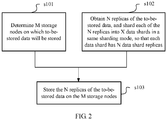
- the method includes the following steps.
- the M data nodes on which the to-be-stored data will be stored may be determined according to a data size of the to-be-stored data and a storage capacity that each data node can provide.
- a quantity of data nodes on which data will be stored may also be a preset fixed value, or a total quantity of storage nodes.
- the quantity M of the data nodes may also be determined according to a value set by a user by using an API interface.
- M data nodes with relatively low load may be selected according to a load status of each node, as the data nodes on which the data will be stored, so as to increase a load balancing degree of an entire distributed storage system.
- the quantity N of the replicas is a total quantity of original data and backup data of the to-be-stored data, that is, the N replicas include the original data of the to-be-stored data and N-1 pieces of backup data of the original data.
- redundant backup needs to be performed on the to-be-stored data. If the quantity N of the replicas of the to-be-stored data is greater, a redundancy degree of the to-be-stored data is higher. Therefore, reliability of the to-be-stored data is higher, but more storage space is also occupied.
- the quantity of data replicas is a preset value, and may be preset by the user or set according to different to-be-stored data every time a storage request is initiated.
- replicas of a same piece of data should be stored on different storage nodes. In this way, it is ensured that other replicas are not lost when a storage node is faulty. Therefore, for a same distributed system, a value of the quantity N of the replicas should be less than or equal to a value of the quantity M of the data nodes.
- the quantity N of the replicas of the to-be-stored data may be determined according to a security requirement of the to-be-stored data.
- a security requirement of the to-be-stored data When the security requirement of the to-be-stored data is higher, the value of the quantity N of the replicas of the to-be-stored data is greater.
- the security requirement of the data may be obtained directly according to a storage request of the user, that is, in different storage requests, the user has different security requirements for the to-be-stored data; or the security requirement of the to-be-stored data may be determined according to preset determining logic, for example, a correspondence between different data types and security requirements, or a correspondence between different user types and security requirements.
- PaaS Platform-as-a-service
- security requirements of data of different applications deployed by the user on the platform are different, and the security requirement of the to-be-stored data may be further determined according to different applications or application types.
- the quantity N of the replicas of the to-be-stored data may be determined according to a data type of the to-be-stored data and a correspondence between the data type and the quantity of the replicas. Therefore, availability of different types of data is protected to different degrees.
- Each of the N replicas is sharded into X data shards in a same sharding mode, so that each data shard has N data shard replicas.
- the quantity X of the shards is a quantity of shards after a replica of the to-be-stored data is sharded.
- primary data and backup data of the to-be-stored data both need to be sharded in the same sharding mode. In this way, primary data shards and backup data shards corresponding to the primary data shards are obtained.
- each data replica is sharded into X same data shards.
- N same shard replicas including the data shard there are N same shard replicas including the data shard. It may be understood that, after the quantity X of the shards of the to-be-stored data is determined, a total of NxX data shards of the to-be-stored data need to be stored on the M nodes.
- the quantity X of the shards may be preset by the user, that is, a same quantity of shards may be used for any to-be-stored data.
- a quantity of shards of the to-be-stored data may be set when the user initiates a storage request.
- the quantity of the data shards stored on the storage nodes is greater if the quantity of the shards is greater. Therefore, a data shard granularity is reduced, the data is stored on the nodes evenly more easily, and load balancing is implemented as much as possible. Therefore, according to a current load balancing status of the distributed storage system, different shard quantities are set for the to-be-stored data. For example, when the distributed system has a higher requirement on load balancing, the shard quantity is dynamically increased, so that the load balancing degree of the distributed system is increased.
- the method followed during storage is: the N data shard replicas of each of the X data shards are respectively stored on N storage nodes in the M storage nodes, and a quantity of data shards whose data shard replicas are stored on same N storage nodes is P or P+1, where P is an integer quotient of X divided by C M N .
- the quantity of the data shards on the same N storage nodes is: for any N data nodes in the distributed system, a quantity of data shards with all N replicas thereof stored on the N data nodes.
- the quantity of the data shards whose data shard replicas are stored on the same N storage nodes is P or P+1, where P is the integer quotient of X divided by C M N .
- P is the integer quotient of X divided by C M N .
- any N data nodes are selected, and a maximum value of a quantity of possible data nodes storing all the N replicas is minimized.
- each data shard is stored on N nodes, that is, a combination of N nodes.
- a total of C M N different combinations may exist for selecting a combination of N nodes in a distributed system including M storage nodes. Therefore, when the quantity X of the shards is less than C M N , different N data shards may be selected for each data shard, that is, a quantity of data shards stored on same N nodes is 1.
- each data shard has three replicas.
- 10 data node combinations are required to store all replicas of three different data nodes, but other 10 data node combinations store all replicas of two different data nodes.
- the following provides a specific storage algorithm by using an example, so as to obtain a storage policy satisfying the foregoing storage mode.
- the algorithm is only a design of a storage policy for storing the to-be-stored data on the storage nodes according to the foregoing principle.
- a person skilled in the art may implement the foregoing storage policy by using multiple different specific algorithms. The algorithms are not illustrated herein one by one.
- the algorithm includes the following steps:
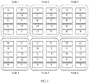
- FIG. 3 shows one of storage policies obtained according to this embodiment of the present invention, for storing to-be-stored data in a distributed system in which a quantity M of data nodes is 6, where a quantity N of replicas of the to-be-stored data is 3 and a quantity X of shards thereof is 20.
- a quantity of data shards stored on same three storage nodes needs to be minimized, that is, each combination of three storage nodes stores three replicas of a data shard.
- any three storage nodes are selected, and the three storage nodes all completely store all three replicas of one data shard only.
- nodes 1, 2, and 3 only completely store all three replicas of a data shard A, but nodes 1, 2, and 4 only completely store all three replicas of a data shard B.
- each data shard is stored on three different data nodes, to cause a complete loss of a data shard, at least three data nodes need to be simultaneously faulty.
- any three data nodes are simultaneously faulty, only one data shard is lost. For example, when the nodes 1, 2, and 3 are faulty, only the data shard A is lost, but other data shards have at least one data shard replica stored on other nodes.
- FIG. 4 illustrates a possible data restoration mode when a node 5 is faulty. Data shard replicas stored on the node may be recovered respectively by using grey replicas on other five data nodes.
- This embodiment of the present invention is applicable to storing data with different quantities of shards and different quantities of replicas in a distributed system, and a quantity of shards and a quantity of replicas may be adjusted flexibly according to different to-be-stored data. Because it is ensured that a quantity of data shards stored on same N nodes is minimized, when N nodes are simultaneously faulty, a quantity of data shards that may be lost is minimized. Therefore, data backup availability is improved. In addition, because a storage policy in which a quantity of shards is greater than a quantity of nodes may be implemented in this solution, a quantity of data shards stored on a single node is increased.
- a method for determining a quantity of shards of to-be-stored data is provided. Higher data availability may be achieved by using the quantity of the shards of the to-be-stored data.
- a method for determining a quantity of data nodes on which the to-be-stored data will be stored and obtaining a quantity of replicas of the to-be-stored data is similar to the method described in S101 and S102 in the foregoing embodiment. Details are not described again herein.
- the shard quantity determined according to this method embodiment may be used for sharding data replicas according to step S102 in the foregoing embodiment. Similarities are not described again herein in this embodiment.
- determining a quantity X of shards of to-be-stored data includes:
- each data shard of the to-be-stored data needs to be stored on the N nodes.
- each data shard should be stored in different combinations of data nodes preferably.
- a change of a ratio of a maximum amount of data that may be lost to a total amount when any three data nodes are faulty is hereinafter described by using an example in which a quantity of data nodes is 6, a quantity of replicas is 3, and sizes of data shards are equal.
- a horizontal coordinate is a quantity X of data shards
- a vertical coordinate is a ratio of a maximum amount of data that may be lost to a total amount when any three data nodes are faulty
- a function graph thereof is shown in the figure.
- the quantity of the data shards is 6, the maximum amount of data lost when three nodes are faulty is 1/6 of all data; if the quantity of the data shards is 7, the maximum amount of data lost when three nodes are faulty is 1/7 of all data; if the quantity of the data shards is 20, the maximum amount of data lost when three nodes are faulty is 1/20 of all data; if the quantity of the data shards is 21, the maximum amount of data lost when three nodes are faulty is 2/21 of all data; if the quantity of the data shards is 40, the maximum amount of data lost when three nodes are faulty is 2/40 of all data; and if the quantity of the data shards is 41, the maximum amount of data lost when three nodes are faulty is 3/41 of all data...
- the quantity X of the shards of the to-be-stored data is equal to the product of the optimal shard base Y and the coefficient K.
- N nodes are faulty, a ratio of a maximum amount of data that may be lost to the total data amount is minimized, that is, data availability is highest.
- the quantity X of the data shards is less than C M N or an integer multiple of C M N
- the quantity X of the shards is closer to C M N or the integer multiple of C M N
- the ratio of the maximum amount of data that may be lost to the total data amount is smaller, and data availability is higher. Therefore, when the quantity X of the shards of the to-be-stored data is less than and closer to the product of the optimal shard base Y and the coefficient K, higher data availability may also be obtained.
- the quantity X of the data shards is C M N or an integer multiple (greater than 1) of C M N
- an optimal value may be obtained in consideration of data availability.
- the optimal value cannot be obtained, when the value is less than and closer to C M N or an integer multiple (greater than 1) of C M N , data availability is higher. Therefore, when the quantity X of the shards is determined, to achieve optimal data availability, C M N or an integer multiple (greater than 1) of C M N should be selected as the quantity X of the shards.
- a final value of X may be determined with reference to an effect that the present invention needs to achieve in a specific scenario.
- a technical effect expected to be achieved is that when N nodes are faulty, a maximum data loss ratio that may be caused is less than Q.
- K is an integer greater than or equal to 1
- KC M N when N nodes are faulty, a maximum data loss ratio that may be caused is monotonically decreased, and a maximum data loss ratio that may be caused and corresponds to a value of X within the interval is K/X.
- K/X should be less than Q, that is, the value of X should be greater than K/Q.
- K/Q when the value of K/Q is less than or equal to (K-1) C M N , setting X to any value within the interval K ⁇ 1 C M N , KC M N may satisfy that a maximum data loss ratio that may be caused is less than Q; when the value of K/Q is greater than (K-1) C M N , setting X to any value within an interval [ K / Q , KC M N may satisfy that a maximum data loss ratio that may be caused is less than Q.
- the coefficient K may be determined according to a load balancing requirement of a distributed storage system.
- the coefficient K is an integer greater than or equal to 1, and is used to determine a multiple of the optimal shard base.
- a value of the coefficient K is greater.
- the value of the quantity X of the shards is equal to or less than the product of the optimal shard base Y and the coefficient K.
- an optimal shard base Y is determined, and further, a quantity of shards is determined according to the optimal shard base. Therefore, on a basis of advantages of the foregoing embodiment, data availability may be further improved. Given a same data node quantity and a same replica quantity, optimal or relatively high data availability may be achieved according to the shard quantity determined according to the optimal shard base. In addition, because the value of the determined shard quantity is always greater than the quantity of nodes, load balancing of the distributed system is improved, and efficiency of concurrent restoration when a node is faulty is improved.
- FIG. 6 is a distributed storage device 600 according to a next embodiment of this application.
- the device 600 may be a node deployed in a distributed storage system, or may be an independent data management apparatus in a distributed storage system.
- the device 600 includes but is not limited to a device such as a computer or a server.
- the device 600 includes a processor 601, a memory 602, a transceiver 603, and a bus 604.
- the transceiver 603 is configured to transmit data to or receive data from an external device (for example, another node in the distributed system or a network device out of the distributed system).
- the processor 601, the memory 602, and the transceiver 603 may be connected by using a bus system or in other manners.
- a bus system or in other manners.
- the memory 602 may store program code.
- the processor 601 is configured to invoke the program code stored in the memory 602, so that the processor is configured to perform operations of S101, S102, and S103 in the foregoing embodiment.
- processor 501 may be further configured to perform fractionalized steps in the foregoing first embodiment or an optional solution.
- the processor 501 may further determine the quantity X of the shards by performing operations of S201 and S202: determine an optimal shard base Y of to-be-stored data according to a quantity N of replicas and a quantity M of storage nodes, where the optimal shard base Y is equal to C M N ; and obtain the quantity X of the shards of the to-be-stored data according to the optimal shard base Y, where the quantity X of the shards of the to-be-stored data is equal to or less than the optimal shard base Y or equal to or less than a natural number multiple of the optimal shard base Y.
- the processor 601 may be a processing unit, or may be a general designation of multiple processing units.
- the processing unit may be a central processing unit (Central Processing Unit, CPU), or may be an application-specific integrated circuit (Application Specific Integrated Circuit, ASIC), or is configured as one or more integrated circuits for implementing the embodiments of this application, for example, one or more microprocessors (digital singnal processor, DSP), or one or more field programmable gate arrays (Field Programmable Gate Array, FPGA).
- CPU Central Processing Unit
- ASIC Application Specific Integrated Circuit
- the memory 603 may be a storage apparatus, or may be a general designation of multiple storage units, and is configured to store executable program code, or parameters, data, and the like that are required for running an application program running apparatus.
- the memory 603 may include a random access memory (RAM), or may include a non-volatile memory (non-volatile memory), for example, a disk storage, or a flash (Flash) memory.
- the bus 604 may be an industry standard architecture (Industry Standard Architecture, ISA) bus, a peripheral component interconnect (Peripheral Component, PCI) bus, an extended industry standard architecture (Extended Industry Standard Architecture, EISA) bus, or the like.
- ISA Industry Standard Architecture
- PCI peripheral component interconnect
- EISA Extended Industry Standard Architecture
- the bus may be categorized as an address bus, a data bus, a control bus, or the like.
- the bus in FIG. 6 is indicated only by a bold line. However, this does not mean that only one bus or one type of bus exists.
- the user equipment may further include an input/output apparatus connected to the bus 604, so that the input/output apparatus is connected to other parts such as the processor 601 by using the bus.
- a user may implement, by using an input device, a step that requires manual configuration or presetting of parameters in this embodiment.
- the input/output apparatus may provide an input interface for an operator, so that the operator selects a control option by using the input interface.
- the input/output apparatus may be another interface, and another external device may be connected by using this interface.
- FIG. 7 is a distributed storage device 700 according to a next embodiment of this application.
- the device 700 may be a node deployed in a distributed storage system, or may be an independent data management apparatus in a distributed storage system.
- the device 700 includes but is not limited to a device such as a computer or a server.
- the device 700 includes a processor 701, a memory 702, a transceiver 703, and a bus 704.
- the transceiver 703 is configured to transmit data to or receive data from an external device (for example, another node in the distributed system or a network device out of the distributed system).
- the processor 701, the memory 702, and the transceiver 703 may be connected by using a bus system or in other manners.
- a bus system or in other manners.
- the memory 702 may store program code.
- the processor 701 is configured to invoke the program code stored in the memory 702, so that the processor is configured to perform the following operations of S201 and S202 to determine a quantity of shards when the shards are stored in the distributed storage system.
- the processor 701 may be further configured to perform fractionalized steps in the foregoing second embodiment or an optional solution.
- the processor 701 may be a processing unit, or may be a general designation of multiple processing units.
- the processing unit may be a central processing unit (Central Processing Unit, CPU), or may be an application-specific integrated circuit (Application Specific Integrated Circuit, ASIC), or is configured as one or more integrated circuits for implementing the embodiments of this application, for example, one or more microprocessors (digital singnal processor, DSP), or one or more field programmable gate arrays (Field Programmable Gate Array, FPGA).
- CPU Central Processing Unit
- ASIC Application Specific Integrated Circuit
- the memory 703 may be a storage apparatus, or may be a general designation of multiple storage units, and is configured to store executable program code, or parameters, data, and the like that are required for running an application program running apparatus.
- the memory 703 may include a random access memory (RAM), or may include a non-volatile memory (non-volatile memory), for example, a disk storage, or a flash (Flash) memory.
- the bus 704 may be an industry standard architecture (Industry Standard Architecture, ISA) bus, a peripheral component interconnect (Peripheral Component, PCI) bus, an extended industry standard architecture (Extended Industry Standard Architecture, EISA) bus, or the like.
- the bus may be categorized as an address bus, a data bus, a control bus, or the like.
- the bus in FIG. 7 is indicated only by a bold line. However, this does not mean that only one bus or one type of bus exists.
- the device may further include an input/output apparatus connected to the bus 704, so that the input/output apparatus is connected to other parts such as the processor 701 by using the bus.
- a user may implement, by using an input device, a step that requires manual configuration or presetting of parameters in this embodiment.
- the input/output apparatus may provide an input interface for an operator, so that the operator selects a control option by using the input interface.
- the input/output apparatus may be another interface, and another external device may be connected by using this interface.
- FIG. 8 is a schematic structural diagram of a distributed storage system 800 according to an embodiment of the present invention.
- the distributed storage system 800 includes a client 810, multiple hard disks 820, and a distributed storage device 830.
- the distributed storage device 830 may be the distributed storage device 600 or the distributed storage device 700 shown in FIG. 6 or FIG. 7 . Details are not described again herein.
- the distributed database engine 102 in FIG. 1 is not the storage apparatus 830 used as a hardware entity in this embodiment of the present invention. Therefore, in this embodiment, a bearing hardware entity corresponding to the data management module 105 improved in the embodiment of the present invention is the distributed storage apparatus 830.
- the distributed storage apparatus 830 stores or reads a data file of a user on multiple hard disks 820 according to a storage/read request sent by the user by using the client 810.
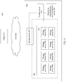
- FIG. 9 is a schematic structural diagram of another distributed storage system 900 according to an embodiment of the present invention.
- the distributed storage system 900 includes a client 910 and a distributed storage server system 920.
- the client 910 may be connected to the distributed storage server system 920 by using the Internet.
- the client 910 may run a client agent program in the distributed storage system.
- the client agent program is used to support various distributed storage applications to access the distributed storage system.
- the client agent program may implement personal online storage and backup, enterprise online storage and backup, application online storage, other emerging storage and backup, or the like.
- the distributed storage server system 920 may include a control server 930, an operation, administration and maintenance (OAM) server 940, a service server 950, a storage resource pool 970, and a storage engine 980.
- OAM operation, administration and maintenance
- the storage engine 980 may be an example of the distributed storage apparatus in FIG. 6 or FIG. 7 .
- the storage engine 980 in this embodiment is used to implement a function of the distributed database engine 102.
- the distributed storage server system 920 further includes other functional servers related to the distributed system, such as the control server 930, the operation, administration and maintenance server 940, and the service server 950.
- the control server 930 is mainly configured to control the distributed storage system to perform various storage services, for example, organize data migration, relocation, and backup, and storage hotspot cancellation.
- the operation, administration and maintenance 940 may provide a configuration interface and an operation and maintenance interface of the storage system, and provide functions such as logs and alarms.
- the service server 950 may provide functions such as service identification and authentication, and complete a service transfer function.
- the storage resource pool 970 may include a storage resource pool formed by physical storage nodes, for example, formed by storage servers or storage boards 960. Virtual nodes in each physical storage node form a storage logic ring. A data file of a user may be stored on a virtual node in the storage resource pool.
- the storage engine 980 may provide main function logic of the distributed storage system.
- the logic may be deployed on one device of the control server 930, the service server 950, and the operation, administration and maintenance 940, or may be deployed on the control server 940, the service server 950, the operation, administration and maintenance 940, and the storage resource pool 970. Therefore, an improvement corresponding to the present invention may also be implemented in the foregoing hardware.
- FIG. 10 is a schematic structural diagram of a distributed storage device 1000 according to an embodiment of the present invention.
- the distributed storage apparatus 1000 includes an obtaining unit 1001 and a storage unit 1002.
- the obtaining unit 1001 is configured to determine M storage nodes on which to-be-stored data will be stored, and obtain N replicas of the to-be-stored data, where the N replicas include original data of the to-be-stored data and N-1 pieces of backup data of the original data, and each of the N replicas is sharded into X data shards in a same sharding mode, so that each data shard has N data shard replicas, where N is less than or equal to M.
- a specific manner or an optional implementation in which the obtaining unit 1001 obtains the quantity of the data nodes and obtains the replicas of the to-be-stored data is not described again in this embodiment.
- the obtaining unit 1001 may obtain the data from an external network or other devices in a distributed storage system by using the transceiver 603 of the distributed storage apparatus in FIG. 6 .
- the obtaining unit 1001 may include an input/output device, so that the data can be obtained in a manner set by a user.
- the obtaining unit 1001 may read a preset value stored in the distributed storage device to obtain the preset numeric value of the data.
- the obtaining unit 1001 shards the replicas when obtaining the to-be-stored data.
- the processor 601 of the distributed storage apparatus in FIG. 6 may be used to invoke the program code stored in the memory 602 to perform the following operation steps to determine the quantity X of the shards: determining an optimal shard base Y of the to-be-stored data according to the quantity N of the replicas and the quantity M of the storage nodes, where the optimal shard base Y is equal to C M N ; and obtaining the quantity X of the shards of the to-be-stored data according to the optimal shard base Y, where the quantity X of the shards of the to-be-stored data is equal to or less than a product of the optimal shard base Y and a coefficient K, and K is an integer greater than or equal to 1.
- the coefficient K is determined according to a load balancing requirement of the distributed storage system, where the coefficient K is a natural number.
- a load balancing degree of the to-be-stored data is higher.
- the quantity X of the shards of the to-be-stored data is determined according to a current load balancing status of the distributed storage system.
- the storage unit 1002 is configured to store the to-be-stored data on the M storage nodes of the distributed system.
- a storage policy during storage complies with the following principle:
- the N data shard replicas of each of the X data shards are respectively stored on N storage nodes in the M storage nodes, and a quantity of data shards whose data shard replicas are stored on same N storage nodes is P or P+1, where P is an integer quotient of X divided by C M N .
- the storage unit 1002 may be implemented by invoking, by using the processor 601 of the distributed storage apparatus in FIG. 6 , the program code stored in the memory 602.
- FIG. 11 is a schematic structural diagram of a distributed storage device 1100 according to an embodiment of the present invention.
- the distributed storage apparatus 1100 includes an obtaining unit 1101 and a determining unit 1102.
- the obtaining unit 1101 is configured to obtain M data nodes on which to-be-stored data will be stored, and a quantity N of replicas of the to-be-stored data. With reference to the method in the second embodiment, a specific manner or an optional implementation in which the obtaining unit 1101 obtains the two pieces of data is not described again in this embodiment.
- the obtaining unit 1101 may obtain the data from an external network or other devices in a distributed storage system by using the transceiver 703 of the distributed storage apparatus in FIG. 7 .
- the obtaining unit 1101 may include an input/output device, so that the data can be obtained in a manner set by a user.
- the obtaining unit 1101 may read a preset value stored in the distributed storage device to obtain the preset numeric value of the data.
- the determining unit 1101 is configured to determines a quantity X of shards of the to-be-stored data, where the quantity of the shards is a quantity of shards that a replica of the to-be-stored data is sharded into, and the quantity X of the shards of the to-be-stored data is equal to or less than C M N or equal to or less than a positive integer multiple of C M N .
- the determining unit 1101 is further configured to determine a coefficient K according to a load balancing requirement of the distributed storage system, where the coefficient K is a positive integer, a load balancing degree of the to-be-stored data is higher if a value of K is greater, and the quantity X of the shards is equal to or less than KC M N .
- the determining unit 1102 may invoke, by using the processor 701 of the distributed storage apparatus in FIG. 7 , the program code stored in the memory 702 to perform the foregoing operation steps to determine the quantity X of the shards.
- the determining unit 1102 may be implemented by invoking, by using the processor 701 of the distributed storage apparatus in FIG. 7 , the program code stored in the memory 702.
- the disclosed system, apparatus, and method may be implemented in other manners.
- the described apparatus embodiment is merely an example.
- the unit division is merely logical function division and may be other division in actual implementation.
- a plurality of units or components may be combined or integrated into another system, or some features may be ignored or not performed.
- the displayed or discussed mutual couplings or direct couplings or communication connections may be implemented by using some interfaces.
- the indirect couplings or communication connections between the apparatuses or units may be implemented in electronic, mechanical, or other forms.
- the units described as separate parts may or may not be physically separate, and parts displayed as units may or may not be physical units, may be located in one position, or may be distributed on a plurality of network units. Some or all of the units may be selected according to actual requirements to achieve the objectives of the solutions of the embodiments.
- functional units in the embodiments of the present invention may be integrated into one processing unit, or each of the units may exist alone physically, or two or more units are integrated into one unit.
- the functions When the functions are implemented in the form of a software functional unit and sold or used as an independent product, the functions may be stored in a computer-readable storage medium. Based on such an understanding, the technical solutions of the present invention essentially, or the part contributing to the prior art, or some of the technical solutions may be implemented in a form of a software product.
- the software product is stored in a storage medium, and includes several instructions for instructing a computer device (which may be a personal computer, a server, or a network device) to perform all or some of the steps of the methods described in the embodiments of the present invention.
- the foregoing storage medium includes: any medium that can store program code, such as a USB flash drive, a removable hard disk, a read-only memory (ROM, Read-Only Memory), a random access memory (RAM, Random Access Memory), a magnetic disk, or an optical disc.
- program code such as a USB flash drive, a removable hard disk, a read-only memory (ROM, Read-Only Memory), a random access memory (RAM, Random Access Memory), a magnetic disk, or an optical disc.
Description
- This application claims priority to Chinese Patent Application No.
201610659118.4 - Embodiments of the present invention relate to the distributed storage field, and more specifically, to a method for storing data shards in a distributed storage system, an apparatus, and a system.
- With fast development of information technologies, an amount of data in an information system database becomes greater. To satisfy mass data storage requirements, a distributed storage system running on multiple servers is applied extensively. In the distributed storage system, multiple database systems run on multiple servers respectively. Before data is stored, the data first needs to be sharded (sharding), and then different data shards are submitted to different servers for storage. Sharding is a horizontal scaling (horizontal scaling) mode in which a large data set is distributed to multiple data nodes, and all the data nodes form a logical database for storing this large data set. Shards are transparent to a user (an application layer). The user does not know which shard server stores data. Storing data by using data shards can break an I/O capability limit of a single-node server and resolve a database scalability problem.
- In addition, to ensure high availability of data and services, a necessary fault tolerance mechanism generally needs to be provided for a distributed database, and redundant backup is performed on each data shard. Storing multiple replicas of a same data shard on different servers can avoid a data shard loss caused when a single server is unavailable.
- In the prior art, a mutual backup mode is generally used to back up data shards in the distributed storage system. A shard quantity of data shards is generally the same as a quantity of storage nodes. Therefore, a primary shard of each data shard is stored on each storage node, and backup shards are stored on any two other storage nodes different from the storage node on which the primary shard is stored. For example, Table 1 illustrates a common storage policy for storing primary data and two pieces of backup data on six data nodes. The data is sharded into six data shards A-F, and each data shard includes one piece of primary data and two pieces of backup data.
Table 1 Storage node Data shard Node 1 A C D Node 2B A C Node 3 C A F Node 4 D B E Node 5 E D F Node 6 F B E - In the prior art, storing the primary shard and the backup shards respectively on different storage nodes can ensure that when a storage node is faulty, the data shard is not lost. The data shard is lost only when all data nodes on which the same data shard is located are faulty. However, when all the data nodes on which the same data shard is located are faulty, a case in which primary data and backup data of two data shards are stored on multiple same nodes may occur. For example, in the example in Table 1, the data shard A and the data shard C are both stored on the
nodes node 6 is faulty, data restoration can be concurrently implemented separately by using a maximum of only one node that stores the data shard F, B, or E, for example, thenode -
US 5,555,404 relates to a database server with a "shared nothing" system architecture. The database server has multiple nodes, each having its own central processing unit, primary and secondary memory for storing database tables and other data structures, and communication channels for communication with other ones of the nodes. The nodes are divided into at least two groups that share no resources. Each database table in the system is divided into fragments distributed for storage purposes over all the nodes in the system. To ensure continued data availability after a node failure, a "primary replica" and a "standby replica" of each fragment are each stored on nodes in different ones of the groups. Database transactions are performed using the primary fragment replicas, and the standby replicas are updated using transaction log records. Every node of the system includes a data dictionary that stores information indicating where each primary and standby fragment replica is stored. The fragments are allocated as evenly as possible among the system nodes using a fragment to node assignment equation. A transaction manager on each node responds to database queries by determining which fragment of a database is being accessed by the query and then forwarding the database query to the node processor on which the primary replica of that fragment is stored. Upon failure of any one of the data processors in the system, each node updates the information in its data dictionary accordingly. In addition, the fragment replicas made unavailable by the node failure are regenerated and stored on the remaining available nodes in the same node group as the failed node. -
CN 101,753,349 discloses a method of upgrading primary and standby copies of data stored in a distributed storage system. - In view of this, embodiments of the present invention provide a method for storing data shards in a distributed storage system, an apparatus, and a system to improve data backup availability and data restoration efficiency.
- According to a first aspect, an embodiment of the present invention provides a method for storing data shards according to
claim 1. - According to a second aspect, an embodiment of the present invention provides a distributed storage device according to claim 7.
- According to a third aspect, an embodiment of the present invention provides a distributed storage system according to claim 8.
- In comparison with the prior art, the present invention provides a method for storing data shards in a distributed environment to improve data availability and data restoration efficiency when a node is faulty.
- To describe the technical solutions in the embodiments of the present invention more clearly, the following briefly describes the accompanying drawings required for describing the embodiments. Apparently, the accompanying drawings in the following description merely show some embodiments of the present invention, and a person of ordinary skill in the art can derive other implementations from these accompanying drawings without creative efforts. All the embodiments or implementations shall fall within the protection scope of the present invention.
-
FIG. 1 is a possible schematic architecture diagram of a system according to the present invention. -
FIG. 2 is a schematic flowchart of determining a shard storage policy in a distributed storage system according to an embodiment of the present invention; -
FIG. 3 is a schematic diagram of a possible shard storage policy in a distributed storage system according to an embodiment of the present invention; -
FIG. 4 is a schematic diagram of node restoration in a possible shard storage policy in a distributed storage system according to an embodiment of the present invention; -
FIG. 5 is an exemplary diagram of a correspondence between a quantity of shards and a data loss ratio when multiple nodes are faulty in a possible scenario according to an embodiment of the present invention; -
FIG. 6 is a schematic structural diagram of a distributed storage device according to an embodiment of the present invention; -
FIG. 7 is a schematic structural diagram of another distributed storage device according to an embodiment of the present invention; -
FIG. 8 is a schematic structural diagram of a distributed storage system according to an embodiment of the present invention; -
FIG. 9 is a schematic structural diagram of another distributed storage system according to an embodiment of the present invention; -
FIG. 10 is a schematic structural diagram of a distributed storage apparatus according to an embodiment of the present invention; and -
FIG. 11 is a schematic structural diagram of another distributed storage apparatus according to an embodiment of the present invention. - The following clearly and completely describes the technical solutions in the embodiments of the present invention with reference to the accompanying drawings in the embodiments of the present invention. Apparently, the described embodiments are some but not all of the embodiments of the present invention. All other embodiments obtained by a person of ordinary skill in the art based on the embodiments of the present invention without creative efforts shall fall within the protection scope of the present invention.
- To help understand the embodiments of the present invention, a system architecture of a distributed storage system to which the present invention is applied is described first. In the distributed storage system, data is stored on multiple independent devices in a distributed manner. In a conventional network storage system, a centralized storage server is used to store all data. The storage server becomes a bottleneck of system performance and also a focus of reliability and security, and cannot satisfy a requirement of a large-scale storage application. The distributed network storage system uses an extensible system architecture, uses multiple storage servers to share storage load, and uses a location server to locate storage information. The distributed network storage system not only improves reliability, availability, and access efficiency of the system, but also is easily extensible.
- As shown in
FIG. 1, FIG. 1 is a schematic architecture diagram of a distributed storage system. It should be noted that, the distributed storage system is described only by using an example, and an application scope of the present invention is not limited to this. The distributed storage system shown in the figure includes a distributeddatabase engine 102 and a distributed data storage node 107. The distributeddatabase engine 102 is a system core. The distributeddatabase engine 102 is responsible for operations such as data parsing, routing, distribution, and merging, and manages numerous storage nodes at a bottom layer. The distributed storage node is a combination of multiple data nodes for storing data. A user may construct data node clusters on different scales flexibly according to requirements. - The distributed
database engine 102 includes an API (Application Programming Interface, application programming interface)module 103, providing an interface for a client to invoke a database. Aresource requesting module 104 determines, according to a storage requirement of the client and a storage capacity of each node provided by the distributed data storage node, a quantity of nodes to be provided for the client according to the current storage requirement. Optionally, a quantity of backup replicas of to-be-stored data may be further determined according to a data reliability requirement submitted by the user. Adata management module 105 determines a storage policy according to requested storage resources, that is, a quantity of data shards, and a correspondence between the data shards and the storage nodes. Adata routing module 106 routes a request from the client according to the storage policy determined by the data management module, shards the data and routes the data shards to the data nodes, or aggregates data of each node and returns the data to the client. - It should be understood that, in the distributed storage system, a function of a module is implemented by a server. Generally, a functional module may be implemented by an independent server. However, in some cases, multiple functional modules may also be implemented by one server, or a functional module is implemented by a cluster formed by multiple servers.
- Referring to
FIG. 2, FIG. 2 is a schematic flowchart ofEmbodiment 1 of the present invention. In this embodiment of the present invention, a method for determining a policy for storing data shards in a distributed storage system is provided. With reference to the foregoing descriptions, a policy for storing data shards is determined mainly by improving thedata management module 105. - In this embodiment of the present invention, a client initiates a data storage request to the distributed storage system, and stores to-be-stored data in the distributed storage system. It should be understood that, in this embodiment, a sequence of steps performed in the method is not limited. Referring to
FIG. 2 , a person skilled in the art may understand that, both S101 and S102 are steps previous to step S103, that is, S101 and S102 may be performed according to any sequence, or one or more steps may be performed concurrently and simultaneously. - As shown in
FIG. 2 , the method includes the following steps. - S101. Determine M data nodes on which to-be-stored data will be stored.
- Specifically, generally, the M data nodes on which the to-be-stored data will be stored may be determined according to a data size of the to-be-stored data and a storage capacity that each data node can provide. In some cases, a quantity of data nodes on which data will be stored may also be a preset fixed value, or a total quantity of storage nodes. In addition, the quantity M of the data nodes may also be determined according to a value set by a user by using an API interface.
- In a design, when the data nodes on which the data will be stored is determined, M data nodes with relatively low load may be selected according to a load status of each node, as the data nodes on which the data will be stored, so as to increase a load balancing degree of an entire distributed storage system.
- S102. Obtain N replicas of the to-be-stored data.
- For ease of description, in the present invention, the quantity N of the replicas is a total quantity of original data and backup data of the to-be-stored data, that is, the N replicas include the original data of the to-be-stored data and N-1 pieces of backup data of the original data. To ensure data availability, redundant backup needs to be performed on the to-be-stored data. If the quantity N of the replicas of the to-be-stored data is greater, a redundancy degree of the to-be-stored data is higher. Therefore, reliability of the to-be-stored data is higher, but more storage space is also occupied. Generally, the quantity of data replicas is a preset value, and may be preset by the user or set according to different to-be-stored data every time a storage request is initiated.
- It may be understood that, to ensure isolation of redundant backup of the replicas, replicas of a same piece of data should be stored on different storage nodes. In this way, it is ensured that other replicas are not lost when a storage node is faulty. Therefore, for a same distributed system, a value of the quantity N of the replicas should be less than or equal to a value of the quantity M of the data nodes.
- Optionally, the quantity N of the replicas of the to-be-stored data may be determined according to a security requirement of the to-be-stored data. When the security requirement of the to-be-stored data is higher, the value of the quantity N of the replicas of the to-be-stored data is greater. The security requirement of the data may be obtained directly according to a storage request of the user, that is, in different storage requests, the user has different security requirements for the to-be-stored data; or the security requirement of the to-be-stored data may be determined according to preset determining logic, for example, a correspondence between different data types and security requirements, or a correspondence between different user types and security requirements. On some server platforms, for example, on a PaaS (Platform-as-a-Service, platform-as-a-service) platform, security requirements of data of different applications deployed by the user on the platform are different, and the security requirement of the to-be-stored data may be further determined according to different applications or application types.
- Optionally, the quantity N of the replicas of the to-be-stored data may be determined according to a data type of the to-be-stored data and a correspondence between the data type and the quantity of the replicas. Therefore, availability of different types of data is protected to different degrees.
- Each of the N replicas is sharded into X data shards in a same sharding mode, so that each data shard has N data shard replicas. The quantity X of the shards is a quantity of shards after a replica of the to-be-stored data is sharded. When shards are stored, primary data and backup data of the to-be-stored data both need to be sharded in the same sharding mode. In this way, primary data shards and backup data shards corresponding to the primary data shards are obtained. After the sharding, each data replica is sharded into X same data shards. Therefore, for a data shard, there are N same shard replicas including the data shard. It may be understood that, after the quantity X of the shards of the to-be-stored data is determined, a total of NxX data shards of the to-be-stored data need to be stored on the M nodes.
- In some cases, the quantity X of the shards may be preset by the user, that is, a same quantity of shards may be used for any to-be-stored data. Alternatively, according to different to-be-stored data, a quantity of shards of the to-be-stored data may be set when the user initiates a storage request.
- Optionally, the quantity of the data shards stored on the storage nodes is greater if the quantity of the shards is greater. Therefore, a data shard granularity is reduced, the data is stored on the nodes evenly more easily, and load balancing is implemented as much as possible. Therefore, according to a current load balancing status of the distributed storage system, different shard quantities are set for the to-be-stored data. For example, when the distributed system has a higher requirement on load balancing, the shard quantity is dynamically increased, so that the load balancing degree of the distributed system is increased.
- S103. Store the N replicas of the to-be-stored data on the M storage nodes.
- Specifically, the method followed during storage is: the N data shard replicas of each of the X data shards are respectively stored on N storage nodes in the M storage nodes, and a quantity of data shards whose data shard replicas are stored on same N storage nodes is P or P+1, where P is an integer quotient of X divided by

- The quantity of the data shards on the same N storage nodes is: for any N data nodes in the distributed system, a quantity of data shards with all N replicas thereof stored on the N data nodes. The quantity of the data shards whose data shard replicas are stored on the same N storage nodes is P or P+1, where P is the integer quotient of X divided by


- For example, when 40 data shards need to be stored, each data shard has three replicas. However, in the distributed system, there are 20 different combinations of three data nodes in total. Therefore, during storage, a quantity of data shards stored on same three storage nodes needs to be minimized, that is, each combination stores all replicas of two different data nodes. When 50 data shards need to be stored, 10 data node combinations are required to store all replicas of three different data nodes, but other 10 data node combinations store all replicas of two different data nodes.
- The following provides a specific storage algorithm by using an example, so as to obtain a storage policy satisfying the foregoing storage mode. It should be understood that, the algorithm is only a design of a storage policy for storing the to-be-stored data on the storage nodes according to the foregoing principle. On a basis of understanding the foregoing allocation principle, a person skilled in the art may implement the foregoing storage policy by using multiple different specific algorithms. The algorithms are not illustrated herein one by one.
- The algorithm includes the following steps:
- 1. numbering X to-
be-stored data shards - 2. numbering all
data nodes - 3. creating a storage allocation table, where the storage allocation table includes


- 4. determining a correspondence between data shards and a data node combination in each row in the storage allocation table, where given a quotient P obtained by dividing the quantity X of the shards by


- 5. storing, according to the determined correspondence, N replicas of each data node on N data nodes corresponding to the data node in a row in the storage allocation table, where the storage policy is a storage policy complying with the foregoing principle.
- To help understand this embodiment, the following provides a specific example of a storage policy obtained according to this method embodiment.
FIG. 3 shows one of storage policies obtained according to this embodiment of the present invention, for storing to-be-stored data in a distributed system in which a quantity M of data nodes is 6, where a quantity N of replicas of the to-be-stored data is 3 and a quantity X of shards thereof is 20. In this policy, because
nodes nodes nodes - In addition, in this example, when any data node is faulty, because replicas of data shards are distributed evenly on other data nodes, the other nodes may all perform data restoration on this node simultaneously. For example, as shown in
FIG. 4, FIG. 4 illustrates a possible data restoration mode when anode 5 is faulty. Data shard replicas stored on the node may be recovered respectively by using grey replicas on other five data nodes. - This embodiment of the present invention is applicable to storing data with different quantities of shards and different quantities of replicas in a distributed system, and a quantity of shards and a quantity of replicas may be adjusted flexibly according to different to-be-stored data. Because it is ensured that a quantity of data shards stored on same N nodes is minimized, when N nodes are simultaneously faulty, a quantity of data shards that may be lost is minimized. Therefore, data backup availability is improved. In addition, because a storage policy in which a quantity of shards is greater than a quantity of nodes may be implemented in this solution, a quantity of data shards stored on a single node is increased. When a single node is faulty, because replicas of the data shards stored on the node are evenly distributed other data nodes, a quantity of data nodes that can participate in data restoration is increased, that is, a quantity of concurrent data recoveries is increased when the node is faulty, and data restoration efficiency is improved.
- The following describes a second method embodiment of the present invention. In this embodiment, a method for determining a quantity of shards of to-be-stored data is provided. Higher data availability may be achieved by using the quantity of the shards of the to-be-stored data. In this embodiment, a method for determining a quantity of data nodes on which the to-be-stored data will be stored and obtaining a quantity of replicas of the to-be-stored data is similar to the method described in S101 and S102 in the foregoing embodiment. Details are not described again herein. In addition, the shard quantity determined according to this method embodiment may be used for sharding data replicas according to step S102 in the foregoing embodiment. Similarities are not described again herein in this embodiment.
- In this embodiment, determining a quantity X of shards of to-be-stored data includes:
- S201. Determine an optimal shard base Y of the to-be-stored data according to a quantity N of replicas and a quantity M of storage nodes, where Y =

- S202. Obtain the quantity X of the shards of the to-be-stored data according to the optimal shard base Y, where the quantity X of the shards of the to-be-stored data is equal to or less than a product of the optimal shard base Y and a coefficient K, and K is an integer greater than or equal to 1.
- As can be known from the foregoing description, when the quantity of the replicas is N and the quantity of the storage nodes is M, and the to-be-stored data is stored on the M nodes, each data shard of the to-be-stored data needs to be stored on the N nodes. There are


- When the quantity X of the shards is greater than


- For ease of understanding, given different shard quantities, a change of a ratio of a maximum amount of data that may be lost to a total amount when any three data nodes are faulty is hereinafter described by using an example in which a quantity of data nodes is 6, a quantity of replicas is 3, and sizes of data shards are equal. As shown in
FIG. 5 , a horizontal coordinate is a quantity X of data shards, a vertical coordinate is a ratio of a maximum amount of data that may be lost to a total amount when any three data nodes are faulty, and a function graph thereof is shown in the figure. - If the quantity of the data shards is 6, the maximum amount of data lost when three nodes are faulty is 1/6 of all data;
if the quantity of the data shards is 7, the maximum amount of data lost when three nodes are faulty is 1/7 of all data;
if the quantity of the data shards is 20, the maximum amount of data lost when three nodes are faulty is 1/20 of all data;
if the quantity of the data shards is 21, the maximum amount of data lost when three nodes are faulty is 2/21 of all data;
if the quantity of the data shards is 40, the maximum amount of data lost when three nodes are faulty is 2/40 of all data; and
if the quantity of the data shards is 41, the maximum amount of data lost when three nodes are faulty is 3/41 of all data... - Therefore, it can be known that, using


- As can be seen, when the quantity X of the data shards is


- Specifically, when considering that the quantity X of the shards is less than


- Optionally, if the quantity of the shards is greater, a load balancing degree that may be implemented when the to-be-stored data is stored on the data nodes is higher; therefore, in this implementation, the coefficient K may be determined according to a load balancing requirement of a distributed storage system. The coefficient K is an integer greater than or equal to 1, and is used to determine a multiple of the optimal shard base. When the load balancing requirement of the to-be-stored data is higher, a value of the coefficient K is greater. The value of the quantity X of the shards is equal to or less than the product of the optimal shard base Y and the coefficient K. That is, when the quantity X of the shards is equal to the product of the optimal shard base Y and the coefficient K, optimal data availability may be obtained, and the load balancing requirement of the distributed storage system is satisfied. However, comprehensively considering other factors, when the value of the quantity X of the shards is not the product of the optimal shard base Y and the coefficient K, if the value of the quantity X of the shards is closer to the product of the optimal shard base Y and the coefficient K, data availability is higher, and the load balancing requirement of the distributed storage system can be satisfied more easily.
- In this embodiment, an optimal shard base Y is determined, and further, a quantity of shards is determined according to the optimal shard base. Therefore, on a basis of advantages of the foregoing embodiment, data availability may be further improved. Given a same data node quantity and a same replica quantity, optimal or relatively high data availability may be achieved according to the shard quantity determined according to the optimal shard base. In addition, because the value of the determined shard quantity is always greater than the quantity of nodes, load balancing of the distributed system is improved, and efficiency of concurrent restoration when a node is faulty is improved.
- Referring to
FIG. 6, FIG. 6 is a distributedstorage device 600 according to a next embodiment of this application. Thedevice 600 may be a node deployed in a distributed storage system, or may be an independent data management apparatus in a distributed storage system. Thedevice 600 includes but is not limited to a device such as a computer or a server. As shown inFIG. 6 , thedevice 600 includes aprocessor 601, amemory 602, atransceiver 603, and a bus 604. Thetransceiver 603 is configured to transmit data to or receive data from an external device (for example, another node in the distributed system or a network device out of the distributed system). There may be one ormore processors 601 in thedevice 600. In some embodiments of this application, theprocessor 601, thememory 602, and thetransceiver 603 may be connected by using a bus system or in other manners. For meanings of terms and examples used in this embodiment, refer to the foregoing embodiment. Details are not described again herein. - The
memory 602 may store program code. Theprocessor 601 is configured to invoke the program code stored in thememory 602, so that the processor is configured to perform operations of S101, S102, and S103 in the foregoing embodiment. - For understanding of the foregoing operations, refer to the descriptions in the first method embodiment. Details are not described again herein.
- Optionally, the processor 501 may be further configured to perform fractionalized steps in the foregoing first embodiment or an optional solution.
- Optionally, in this embodiment, when determining a quantity X of shards, the processor 501 may further determine the quantity X of the shards by performing operations of S201 and S202: determine an optimal shard base Y of to-be-stored data according to a quantity N of replicas and a quantity M of storage nodes, where the optimal shard base Y is equal to

- For understanding of performing the foregoing steps, refer to the descriptions in the foregoing second embodiment. The foregoing steps may also be extended or fractionalized with reference to the foregoing second embodiment.
- It should be noted that, herein the
processor 601 may be a processing unit, or may be a general designation of multiple processing units. For example, the processing unit may be a central processing unit (Central Processing Unit, CPU), or may be an application-specific integrated circuit (Application Specific Integrated Circuit, ASIC), or is configured as one or more integrated circuits for implementing the embodiments of this application, for example, one or more microprocessors (digital singnal processor, DSP), or one or more field programmable gate arrays (Field Programmable Gate Array, FPGA). - The
memory 603 may be a storage apparatus, or may be a general designation of multiple storage units, and is configured to store executable program code, or parameters, data, and the like that are required for running an application program running apparatus. In addition, thememory 603 may include a random access memory (RAM), or may include a non-volatile memory (non-volatile memory), for example, a disk storage, or a flash (Flash) memory. - The bus 604 may be an industry standard architecture (Industry Standard Architecture, ISA) bus, a peripheral component interconnect (Peripheral Component, PCI) bus, an extended industry standard architecture (Extended Industry Standard Architecture, EISA) bus, or the like. The bus may be categorized as an address bus, a data bus, a control bus, or the like. For ease of indicating, the bus in
FIG. 6 is indicated only by a bold line. However, this does not mean that only one bus or one type of bus exists. - The user equipment may further include an input/output apparatus connected to the bus 604, so that the input/output apparatus is connected to other parts such as the
processor 601 by using the bus. A user may implement, by using an input device, a step that requires manual configuration or presetting of parameters in this embodiment. The input/output apparatus may provide an input interface for an operator, so that the operator selects a control option by using the input interface. Alternatively, the input/output apparatus may be another interface, and another external device may be connected by using this interface. - Referring to
FIG. 7, FIG. 7 is a distributedstorage device 700 according to a next embodiment of this application. Thedevice 700 may be a node deployed in a distributed storage system, or may be an independent data management apparatus in a distributed storage system. Thedevice 700 includes but is not limited to a device such as a computer or a server. As shown inFIG. 7 , thedevice 700 includes aprocessor 701, amemory 702, atransceiver 703, and a bus 704. Thetransceiver 703 is configured to transmit data to or receive data from an external device (for example, another node in the distributed system or a network device out of the distributed system). There may be one ormore processors 701 in thedevice 700. In some embodiments of this application, theprocessor 701, thememory 702, and thetransceiver 703 may be connected by using a bus system or in other manners. For meanings of terms and examples used in this embodiment, refer to the foregoing embodiment. Details are not described again herein. - The
memory 702 may store program code. Theprocessor 701 is configured to invoke the program code stored in thememory 702, so that the processor is configured to perform the following operations of S201 and S202 to determine a quantity of shards when the shards are stored in the distributed storage system. - For understanding of the foregoing operations, refer to the descriptions in the second method embodiment. Details are not described again herein.
- Optionally, the
processor 701 may be further configured to perform fractionalized steps in the foregoing second embodiment or an optional solution. - It should be noted that, herein the
processor 701 may be a processing unit, or may be a general designation of multiple processing units. For example, the processing unit may be a central processing unit (Central Processing Unit, CPU), or may be an application-specific integrated circuit (Application Specific Integrated Circuit, ASIC), or is configured as one or more integrated circuits for implementing the embodiments of this application, for example, one or more microprocessors (digital singnal processor, DSP), or one or more field programmable gate arrays (Field Programmable Gate Array, FPGA). - The
memory 703 may be a storage apparatus, or may be a general designation of multiple storage units, and is configured to store executable program code, or parameters, data, and the like that are required for running an application program running apparatus. In addition, thememory 703 may include a random access memory (RAM), or may include a non-volatile memory (non-volatile memory), for example, a disk storage, or a flash (Flash) memory. - The bus 704 may be an industry standard architecture (Industry Standard Architecture, ISA) bus, a peripheral component interconnect (Peripheral Component, PCI) bus, an extended industry standard architecture (Extended Industry Standard Architecture, EISA) bus, or the like. The bus may be categorized as an address bus, a data bus, a control bus, or the like. For ease of indicating, the bus in
FIG. 7 is indicated only by a bold line. However, this does not mean that only one bus or one type of bus exists. - The device may further include an input/output apparatus connected to the bus 704, so that the input/output apparatus is connected to other parts such as the
processor 701 by using the bus. A user may implement, by using an input device, a step that requires manual configuration or presetting of parameters in this embodiment. The input/output apparatus may provide an input interface for an operator, so that the operator selects a control option by using the input interface. Alternatively, the input/output apparatus may be another interface, and another external device may be connected by using this interface. -
FIG. 8 is a schematic structural diagram of a distributedstorage system 800 according to an embodiment of the present invention. The distributedstorage system 800 includes aclient 810, multiplehard disks 820, and a distributed storage device 830. The distributed storage device 830 may be the distributedstorage device 600 or the distributedstorage device 700 shown inFIG. 6 orFIG. 7 . Details are not described again herein. - For understanding hardware entities in the distributed system provided by this embodiment, refer to the foregoing distributed system architecture in
FIG. 1 . The distributeddatabase engine 102 inFIG. 1 is not the storage apparatus 830 used as a hardware entity in this embodiment of the present invention. Therefore, in this embodiment, a bearing hardware entity corresponding to thedata management module 105 improved in the embodiment of the present invention is the distributed storage apparatus 830. - The distributed storage apparatus 830 stores or reads a data file of a user on multiple
hard disks 820 according to a storage/read request sent by the user by using theclient 810. -
FIG. 9 is a schematic structural diagram of another distributedstorage system 900 according to an embodiment of the present invention. The distributedstorage system 900 includes aclient 910 and a distributedstorage server system 920. - The
client 910 may be connected to the distributedstorage server system 920 by using the Internet. - The
client 910 may run a client agent program in the distributed storage system. The client agent program is used to support various distributed storage applications to access the distributed storage system. For example, the client agent program may implement personal online storage and backup, enterprise online storage and backup, application online storage, other emerging storage and backup, or the like. - The distributed
storage server system 920 may include acontrol server 930, an operation, administration and maintenance (OAM) server 940, aservice server 950, astorage resource pool 970, and astorage engine 980. Herein thestorage engine 980 may be an example of the distributed storage apparatus inFIG. 6 orFIG. 7 . - For understanding hardware apparatuses in this embodiment, refer to the foregoing distributed architecture in
FIG. 1 . Thestorage engine 980 in this embodiment is used to implement a function of the distributeddatabase engine 102. However, the distributedstorage server system 920 further includes other functional servers related to the distributed system, such as thecontrol server 930, the operation, administration and maintenance server 940, and theservice server 950. - The
control server 930 is mainly configured to control the distributed storage system to perform various storage services, for example, organize data migration, relocation, and backup, and storage hotspot cancellation. - The operation, administration and maintenance 940 may provide a configuration interface and an operation and maintenance interface of the storage system, and provide functions such as logs and alarms.
- The
service server 950 may provide functions such as service identification and authentication, and complete a service transfer function. - The
storage resource pool 970 may include a storage resource pool formed by physical storage nodes, for example, formed by storage servers orstorage boards 960. Virtual nodes in each physical storage node form a storage logic ring. A data file of a user may be stored on a virtual node in the storage resource pool. - The
storage engine 980 may provide main function logic of the distributed storage system. The logic may be deployed on one device of thecontrol server 930, theservice server 950, and the operation, administration and maintenance 940, or may be deployed on the control server 940, theservice server 950, the operation, administration and maintenance 940, and thestorage resource pool 970. Therefore, an improvement corresponding to the present invention may also be implemented in the foregoing hardware. -
FIG. 10 is a schematic structural diagram of a distributedstorage device 1000 according to an embodiment of the present invention. The distributedstorage apparatus 1000 includes an obtainingunit 1001 and astorage unit 1002. - The obtaining
unit 1001 is configured to determine M storage nodes on which to-be-stored data will be stored, and obtain N replicas of the to-be-stored data, where the N replicas include original data of the to-be-stored data and N-1 pieces of backup data of the original data, and each of the N replicas is sharded into X data shards in a same sharding mode, so that each data shard has N data shard replicas, where N is less than or equal to M. With reference to the method in the first embodiment, a specific manner or an optional implementation in which the obtainingunit 1001 obtains the quantity of the data nodes and obtains the replicas of the to-be-stored data is not described again in this embodiment. - With reference to the foregoing apparatus embodiment, the obtaining
unit 1001 may obtain the data from an external network or other devices in a distributed storage system by using thetransceiver 603 of the distributed storage apparatus inFIG. 6 . Alternatively, the obtainingunit 1001 may include an input/output device, so that the data can be obtained in a manner set by a user. In addition, the obtainingunit 1001 may read a preset value stored in the distributed storage device to obtain the preset numeric value of the data. - Optionally, in this embodiment, the obtaining
unit 1001 shards the replicas when obtaining the to-be-stored data. Further, theprocessor 601 of the distributed storage apparatus inFIG. 6 may be used to invoke the program code stored in thememory 602 to perform the following operation steps to determine the quantity X of the shards: determining an optimal shard base Y of the to-be-stored data according to the quantity N of the replicas and the quantity M of the storage nodes, where the optimal shard base Y is equal to
- Optionally, the coefficient K is determined according to a load balancing requirement of the distributed storage system, where the coefficient K is a natural number. When a value of K is greater, a load balancing degree of the to-be-stored data is higher.
- Optionally, the quantity X of the shards of the to-be-stored data is determined according to a current load balancing status of the distributed storage system.
- The
storage unit 1002 is configured to store the to-be-stored data on the M storage nodes of the distributed system. Specifically, a storage policy during storage complies with the following principle: The N data shard replicas of each of the X data shards are respectively stored on N storage nodes in the M storage nodes, and a quantity of data shards whose data shard replicas are stored on same N storage nodes is P or P+1, where P is an integer quotient of X divided by
- With reference to the foregoing apparatus embodiment, the
storage unit 1002 may be implemented by invoking, by using theprocessor 601 of the distributed storage apparatus inFIG. 6 , the program code stored in thememory 602. - For understanding of performing the foregoing steps, refer to the descriptions in the foregoing first or second embodiment. The foregoing steps may also be extended or fractionalized with reference to the foregoing embodiment.
-
FIG. 11 is a schematic structural diagram of a distributedstorage device 1100 according to an embodiment of the present invention. The distributedstorage apparatus 1100 includes an obtainingunit 1101 and a determiningunit 1102. - The obtaining
unit 1101 is configured to obtain M data nodes on which to-be-stored data will be stored, and a quantity N of replicas of the to-be-stored data. With reference to the method in the second embodiment, a specific manner or an optional implementation in which the obtainingunit 1101 obtains the two pieces of data is not described again in this embodiment. - With reference to the foregoing apparatus embodiment, the obtaining
unit 1101 may obtain the data from an external network or other devices in a distributed storage system by using thetransceiver 703 of the distributed storage apparatus inFIG. 7 . Alternatively, the obtainingunit 1101 may include an input/output device, so that the data can be obtained in a manner set by a user. In addition, the obtainingunit 1101 may read a preset value stored in the distributed storage device to obtain the preset numeric value of the data. - The determining
unit 1101 is configured to determines a quantity X of shards of the to-be-stored data, where the quantity of the shards is a quantity of shards that a replica of the to-be-stored data is sharded into, and the quantity X of the shards of the to-be-stored data is equal to or less than

- Optionally, the determining
unit 1101 is further configured to determine a coefficient K according to a load balancing requirement of the distributed storage system, where the coefficient K is a positive integer, a load balancing degree of the to-be-stored data is higher if a value of K is greater, and the quantity X of the shards is equal to or less than
- The determining
unit 1102 may invoke, by using theprocessor 701 of the distributed storage apparatus inFIG. 7 , the program code stored in thememory 702 to perform the foregoing operation steps to determine the quantity X of the shards. - With reference to the foregoing apparatus embodiment, the determining
unit 1102 may be implemented by invoking, by using theprocessor 701 of the distributed storage apparatus inFIG. 7 , the program code stored in thememory 702. - For understanding of performing the foregoing steps, refer to the descriptions in the foregoing first or second embodiment. The foregoing steps may also be extended or fractionalized with reference to the foregoing embodiment.
- A person of ordinary skill in the art may be aware that, in combination with the examples described in the embodiments disclosed in this specification, units and algorithm steps may be implemented by electronic hardware or a combination of computer software and electronic hardware. Whether the functions are performed by hardware or software depends on particular applications and design constraint conditions of the technical solutions. A person skilled in the art may use different methods to implement the described functions for each particular application, but it should not be considered that the implementation goes beyond the scope of the present invention.
- It may be clearly understood by a person skilled in the art that, for the purpose of convenient and brief description, for a detailed working process of the foregoing system, apparatus, and unit, reference may be made to a corresponding process in the foregoing method embodiments, and details are not described herein again.
- In the several embodiments provided in this application, it should be understood that the disclosed system, apparatus, and method may be implemented in other manners. For example, the described apparatus embodiment is merely an example. For example, the unit division is merely logical function division and may be other division in actual implementation. For example, a plurality of units or components may be combined or integrated into another system, or some features may be ignored or not performed. In addition, the displayed or discussed mutual couplings or direct couplings or communication connections may be implemented by using some interfaces. The indirect couplings or communication connections between the apparatuses or units may be implemented in electronic, mechanical, or other forms.
- The units described as separate parts may or may not be physically separate, and parts displayed as units may or may not be physical units, may be located in one position, or may be distributed on a plurality of network units. Some or all of the units may be selected according to actual requirements to achieve the objectives of the solutions of the embodiments.
- In addition, functional units in the embodiments of the present invention may be integrated into one processing unit, or each of the units may exist alone physically, or two or more units are integrated into one unit.
- When the functions are implemented in the form of a software functional unit and sold or used as an independent product, the functions may be stored in a computer-readable storage medium. Based on such an understanding, the technical solutions of the present invention essentially, or the part contributing to the prior art, or some of the technical solutions may be implemented in a form of a software product. The software product is stored in a storage medium, and includes several instructions for instructing a computer device (which may be a personal computer, a server, or a network device) to perform all or some of the steps of the methods described in the embodiments of the present invention. The foregoing storage medium includes: any medium that can store program code, such as a USB flash drive, a removable hard disk, a read-only memory (ROM, Read-Only Memory), a random access memory (RAM, Random Access Memory), a magnetic disk, or an optical disc.
- The foregoing descriptions are merely specific implementations of the present invention, but are not intended to limit the protection scope of the present invention. Any variation or replacement readily figured out by a person skilled in the art within the technical scope disclosed in the present invention shall fall within the protection scope of the present invention. Therefore, the protection scope of the present invention shall be subject to the protection scope of the claims.
Claims (8)
- A method for storing data shards, wherein the method comprises:determining (S101) M storage nodes on which data will be stored;obtaining (S102) N replicas of the data, wherein the N replicas comprise original data of the data and N-1 pieces of backup data of the original data, and sharding each of the N replicas into X data shards in a same sharding mode, so that each data shard has N data shard replicas, wherein N is less than or equal to M; andstoring (S103) the N replicas of the data on the M storage nodes, wherein the N data shard replicas of each of the X data shards are respectively stored on N storage nodes in the M storage nodes, and a quantity of data shards whose data shard replicas are stored on same N storage nodes is P or P+1, wherein P is an integer quotient of X divided by
 wherein the storing comprises:determining
 determining the integer quotient P obtained by dividing the quantity X of the shards by
 selecting, from the

- The method according to claim 1, wherein the sharding each of the N replicas into X data shards in a same sharding mode specifically comprises:determining (S201) an optimal shard base Y of the data according to the quantity N of the replicas and the quantity M of the storage nodes, wherein the optimal shard base Y is equal to
 sharding each of the N replicas into the X data shards in the same sharding mode.
 - The method according to claim 1, wherein the sharding each of the N replicas into X data shards in a same sharding mode specifically comprises:determining (S201) an optimal shard base Y of the data according to the quantity N of the replicas and the quantity M of the storage nodes, wherein the optimal shard base Y is equal to
 obtaining (S202) the quantity X of the shards of the data according to the optimal shard base Y, wherein the quantity X of the shards of the data is less than a product of the optimal shard base Y and a coefficient K, and K is an integer greater than or equal to 1; andsharding each of the N replicas into the X data shards in the same sharding mode.
 - The method according to claim 2 or 3, wherein the coefficient K is determined according to a load balancing requirement of a distributed storage system, and if a value of K is greater, a load balancing degree of the data is higher.
- The method according to any one of claims 1 to 4, wherein the obtaining the quantity N of the replicas of the data specifically comprises:
determining the quantity N of the replicas of the data according to a security requirement of the data, wherein if the quantity N of the replicas is greater, a higher security requirement of the data can be satisfied. - The method according to claim 1, wherein the quantity X of the data shards is determined according to a load balancing requirement of a distributed storage system, and if a value of X is greater, a load balancing degree of the data is higher.
- A distributed storage device (700), wherein the device is used in a distributed storage system comprising at least two storage nodes, and configured to determine a policy for storing shards of data, and the device comprises:a processor (701), and a memory (702) connected to the processor, whereinthe processor invokes an instruction stored in the memory, so that the processor is configured to perform the method according to any one of claims 1 to 6.
- A distributed storage system, wherein the system comprises at least two storage nodes and at least one management device, the management device is configured to determine a policy for storing shards of data, and the management device comprises:a processor, and a memory connected to the processor, whereinthe processor invokes an instruction stored in the memory, so that the processor is configured to perform the method according to any one of claims 1 to 6.
Applications Claiming Priority (2)
| Application Number | Priority Date | Filing Date | Title |
|---|---|---|---|
| CN201610659118.4A CN106302702B (en) | 2016-08-10 | 2016-08-10 | Data fragment storage method, device and system |
| PCT/CN2017/079971 WO2018028229A1 (en) | 2016-08-10 | 2017-04-10 | Data shard storage method, device and system |
Publications (3)
| Publication Number | Publication Date |
|---|---|
| EP3487149A4 EP3487149A4 (en) | 2019-05-22 |
| EP3487149A1 EP3487149A1 (en) | 2019-05-22 |
| EP3487149B1 true EP3487149B1 (en) | 2020-04-29 |
Family
ID=57670023
Family Applications (1)
| Application Number | Title | Priority Date | Filing Date |
|---|---|---|---|
| EP17838361.8A Active EP3487149B1 (en) | 2016-08-10 | 2017-04-10 | Data shard storage method, device and system |
Country Status (4)
| Country | Link |
|---|---|
| US (1) | US10942828B2 (en) |
| EP (1) | EP3487149B1 (en) |
| CN (1) | CN106302702B (en) |
| WO (1) | WO2018028229A1 (en) |
Families Citing this family (34)
| Publication number | Priority date | Publication date | Assignee | Title |
|---|---|---|---|---|
| CN106302702B (en) * | 2016-08-10 | 2020-03-20 | 华为技术有限公司 | Data fragment storage method, device and system |
| US11461273B1 (en) * | 2016-12-20 | 2022-10-04 | Pure Storage, Inc. | Modifying storage distribution in a storage system that includes one or more storage devices |
| CN108572976A (en) * | 2017-03-10 | 2018-09-25 | 华为软件技术有限公司 | Data reconstruction method, relevant device and system in a kind of distributed data base |
| CN107395745A (en) * | 2017-08-20 | 2017-11-24 | 长沙曙通信息科技有限公司 | A kind of distributed memory system data disperse Realization of Storing |
| CN109660493B (en) * | 2017-10-11 | 2020-12-18 | 南京南瑞继保电气有限公司 | New energy centralized control cloud storage method based on block chain |
| WO2019080015A1 (en) | 2017-10-25 | 2019-05-02 | 华为技术有限公司 | Data reading and writing method and device, and storage server |
| CN109992196B (en) * | 2017-12-29 | 2022-05-17 | 杭州海康威视数字技术股份有限公司 | Index data storage method and device and storage system |
| CN108491167B (en) * | 2018-03-29 | 2020-12-04 | 重庆大学 | Industrial process working condition data rapid random distribution storage method |
| EP3785207A1 (en) * | 2018-04-27 | 2021-03-03 | Nchain Holdings Limited | Partitioning a blockchain network |
| CN108664223B (en) * | 2018-05-18 | 2021-07-02 | 百度在线网络技术(北京)有限公司 | Distributed storage method and device, computer equipment and storage medium |
| CN108769171B (en) * | 2018-05-18 | 2021-09-17 | 百度在线网络技术(北京)有限公司 | Copy keeping verification method, device, equipment and storage medium for distributed storage |
| CN108874585B (en) * | 2018-05-25 | 2021-01-22 | 南京云信达科技有限公司 | File backup method, device and system |
| CN110535898B (en) * | 2018-05-25 | 2022-10-04 | 许继集团有限公司 | Method for storing and complementing copies and selecting nodes in big data storage and management system |
| US10764258B2 (en) | 2018-06-29 | 2020-09-01 | Arm Ip Limited | Blockchain infrastructure for securing and/or managing electronic artifacts |
| CN110798492B (en) * | 2018-08-02 | 2022-08-09 | 杭州海康威视数字技术股份有限公司 | Data storage method and device and data processing system |
| CN109062736A (en) * | 2018-08-20 | 2018-12-21 | 广州视源电子科技股份有限公司 | A kind of data back up method, device, equipment and storage medium |
| CN109597826B (en) * | 2018-09-04 | 2023-02-21 | 创新先进技术有限公司 | Data processing method and device, electronic equipment and computer readable storage medium |
| CN110874288A (en) * | 2018-09-04 | 2020-03-10 | 北京奇虎科技有限公司 | Management method and device for Redis cluster cache data |
| CN110633378A (en) * | 2019-08-19 | 2019-12-31 | 杭州欧若数网科技有限公司 | Graph database construction method supporting super-large scale relational network |
| CN110795702A (en) * | 2019-10-12 | 2020-02-14 | 山东英信计算机技术有限公司 | Software anti-cracking method, device, equipment and medium |
| US11074129B2 (en) | 2019-10-31 | 2021-07-27 | Western Digital Technologies, Inc. | Erasure coded data shards containing multiple data objects |
| CN111444274B (en) * | 2020-03-26 | 2021-04-30 | 上海依图网络科技有限公司 | Data synchronization method, data synchronization system, and apparatus, medium, and system thereof |
| CN111428271A (en) * | 2020-04-17 | 2020-07-17 | 上海坤仪金科信息技术有限公司 | Block chain cloud storage user data security solution method |
| CN111835848B (en) * | 2020-07-10 | 2022-08-23 | 北京字节跳动网络技术有限公司 | Data fragmentation method and device, electronic equipment and computer readable medium |
| CN113297005B (en) * | 2020-07-27 | 2024-01-05 | 阿里巴巴集团控股有限公司 | Data processing method, device and equipment |
| CN112231398A (en) * | 2020-09-25 | 2021-01-15 | 北京金山云网络技术有限公司 | Data storage method, device, equipment and storage medium |
| CN112711382B (en) * | 2020-12-31 | 2024-04-26 | 百果园技术(新加坡)有限公司 | Data storage method and device based on distributed system and storage node |
| CN113268472B (en) * | 2021-07-15 | 2021-10-12 | 北京华品博睿网络技术有限公司 | Distributed data storage system and method |
| CN113609090A (en) * | 2021-08-06 | 2021-11-05 | 杭州网易云音乐科技有限公司 | Data storage method and device, computer readable storage medium and electronic equipment |
| CN113505027B (en) * | 2021-09-10 | 2022-03-01 | 深圳市科力锐科技有限公司 | Business system backup method, device, equipment and storage medium |
| CN113961149B (en) * | 2021-10-29 | 2024-01-26 | 国网江苏省电力有限公司营销服务中心 | Polymorphic data storage system and method for electric power information system |
| CN114398371A (en) * | 2022-01-13 | 2022-04-26 | 九有技术(深圳)有限公司 | Multi-copy fragmentation method, device, equipment and storage medium for database cluster system |
| CN114925073B (en) * | 2022-06-14 | 2024-04-16 | 深圳九有数据库有限公司 | Distributed database system supporting flexible dynamic fragmentation and implementation method thereof |
| CN117494146B (en) * | 2023-12-29 | 2024-04-26 | 山东街景智能制造科技股份有限公司 | Model database management system |
Family Cites Families (14)
| Publication number | Priority date | Publication date | Assignee | Title |
|---|---|---|---|---|
| US5555404A (en) * | 1992-03-17 | 1996-09-10 | Telenor As | Continuously available database server having multiple groups of nodes with minimum intersecting sets of database fragment replicas |
| US7778972B1 (en) | 2005-12-29 | 2010-08-17 | Amazon Technologies, Inc. | Dynamic object replication within a distributed storage system |
| US7653782B2 (en) * | 2006-05-23 | 2010-01-26 | Dell Products L.P. | Method for host bus adapter-based storage partitioning and mapping across shared physical drives |
| CN101753349B (en) * | 2008-12-09 | 2012-08-15 | 中国移动通信集团公司 | Upgrading method of data node, upgrade dispatching node as well as upgrading system |
| JP6122126B2 (en) * | 2013-08-27 | 2017-04-26 | 株式会社東芝 | Database system, program, and data processing method |
| CN104468651B (en) | 2013-09-17 | 2019-09-10 | 南京中兴新软件有限责任公司 | Distributed more copy data storage methods and device |
| US10620830B2 (en) * | 2013-12-18 | 2020-04-14 | Amazon Technologies, Inc. | Reconciling volumelets in volume cohorts |
| US10120924B2 (en) * | 2014-03-31 | 2018-11-06 | Akamai Technologies, Inc. | Quarantine and repair of replicas in a quorum-based data storage system |
| CN105335297B (en) * | 2014-08-06 | 2018-05-08 | 阿里巴巴集团控股有限公司 | Data processing method, device and system based on distributed memory and database |
| CN104376087B (en) * | 2014-11-19 | 2017-09-29 | 天津南大通用数据技术股份有限公司 | A kind of computational methods using the distributed data base load balancing for intersecting backup |
| CN105740295B (en) * | 2014-12-12 | 2019-06-14 | 中国移动通信集团公司 | A kind of processing method and processing device of distributed data |
| CN104580427B (en) * | 2014-12-27 | 2018-09-04 | 北京奇虎科技有限公司 | Principal and subordinate's balance method and device in a kind of distributed memory system |
| US20160306822A1 (en) * | 2015-04-17 | 2016-10-20 | Samsung Electronics Co., Ltd. | Load balancing of queries in replication enabled ssd storage |
| CN106302702B (en) * | 2016-08-10 | 2020-03-20 | 华为技术有限公司 | Data fragment storage method, device and system |
-
2016
- 2016-08-10 CN CN201610659118.4A patent/CN106302702B/en active Active
-
2017
- 2017-04-10 WO PCT/CN2017/079971 patent/WO2018028229A1/en unknown
- 2017-04-10 EP EP17838361.8A patent/EP3487149B1/en active Active
-
2019
- 2019-02-07 US US16/270,048 patent/US10942828B2/en active Active
Non-Patent Citations (1)
| Title |
|---|
| None * |
Also Published As
| Publication number | Publication date |
|---|---|
| EP3487149A4 (en) | 2019-05-22 |
| US10942828B2 (en) | 2021-03-09 |
| CN106302702A (en) | 2017-01-04 |
| CN106302702B (en) | 2020-03-20 |
| WO2018028229A1 (en) | 2018-02-15 |
| US20190171537A1 (en) | 2019-06-06 |
| EP3487149A1 (en) | 2019-05-22 |
Similar Documents
| Publication | Publication Date | Title |
|---|---|---|
| EP3487149B1 (en) | Data shard storage method, device and system | |
| US11385803B2 (en) | Cycling out dispersed storage processing units from access pools to perform expensive operations | |
| US10942812B2 (en) | System and method for building a point-in-time snapshot of an eventually-consistent data store | |
| US10019192B2 (en) | Policy-based hierarchical data protection in distributed storage | |
| US5555404A (en) | Continuously available database server having multiple groups of nodes with minimum intersecting sets of database fragment replicas | |
| US5423037A (en) | Continuously available database server having multiple groups of nodes, each group maintaining a database copy with fragments stored on multiple nodes | |
| US7062674B2 (en) | Multiple computer system and method for assigning logical computers on the same system | |
| US7730057B2 (en) | Computer data systems implemented using a virtual solution architecture | |
| US20170353580A1 (en) | Routing vault access requests in a dispersed storage network | |
| US20160266832A1 (en) | Optimization of in-memory data grid placement | |
| US9916215B2 (en) | System and method for selectively utilizing memory available in a redundant host in a cluster for virtual machines | |
| US11442827B2 (en) | Policy-based hierarchical data protection in distributed storage | |
| US20130124916A1 (en) | Layout of mirrored databases across different servers for failover | |
| CN109873714B (en) | Cloud computing node configuration updating method and terminal equipment | |
| US11681582B2 (en) | Write lock conflicts in a storage network | |
| US9747323B1 (en) | Method for reconstruction of a distributed lock state after a node addition or removal using a consistent hash | |
| US20230100323A1 (en) | Memory Allocation for Block Rebuilding in a Storage Network | |
| US10498804B1 (en) | Load balancing Hadoop distributed file system operations in a non-native operating system | |
| US10481963B1 (en) | Load-balancing for achieving transaction fault tolerance | |
| US10884648B2 (en) | Temporary relocation of data within local storage of a dispersed storage network | |
| WO2016188135A1 (en) | Cpu resource configuration method for cluster router and cluster router | |
| US10956056B2 (en) | Applying dynamic routing protocols to route DSN access requests | |
| CN117560370A (en) | Fragment storage method and device | |
| JP2023151189A (en) | Storage system and method for controlling the same | |
| CN117851040A (en) | Resource integration method for realizing cloud platform computing nodes based on dynamic resource load |
Legal Events
| Date | Code | Title | Description |
|---|---|---|---|
| STAA | Information on the status of an ep patent application or granted ep patent |
Free format text: STATUS: THE INTERNATIONAL PUBLICATION HAS BEEN MADE |
|
| PUAI | Public reference made under article 153(3) epc to a published international application that has entered the european phase |
Free format text: ORIGINAL CODE: 0009012 |
|
| STAA | Information on the status of an ep patent application or granted ep patent |
Free format text: STATUS: REQUEST FOR EXAMINATION WAS MADE |
|
| 17P | Request for examination filed |
Effective date: 20190218 |
|
| A4 | Supplementary search report drawn up and despatched |
Effective date: 20190325 |
|
| AK | Designated contracting states |
Kind code of ref document: A1 Designated state(s): AL AT BE BG CH CY CZ DE DK EE ES FI FR GB GR HR HU IE IS IT LI LT LU LV MC MK MT NL NO PL PT RO RS SE SI SK SM TR |
|
| AX | Request for extension of the european patent |
Extension state: BA ME |
|
| DAV | Request for validation of the european patent (deleted) | ||
| DAX | Request for extension of the european patent (deleted) | ||
| GRAP | Despatch of communication of intention to grant a patent |
Free format text: ORIGINAL CODE: EPIDOSNIGR1 |
|
| STAA | Information on the status of an ep patent application or granted ep patent |
Free format text: STATUS: GRANT OF PATENT IS INTENDED |
|
| INTG | Intention to grant announced |
Effective date: 20200117 |
|
| GRAS | Grant fee paid |
Free format text: ORIGINAL CODE: EPIDOSNIGR3 |
|
| GRAA | (expected) grant |
Free format text: ORIGINAL CODE: 0009210 |
|
| STAA | Information on the status of an ep patent application or granted ep patent |
Free format text: STATUS: THE PATENT HAS BEEN GRANTED |
|
| AK | Designated contracting states |
Kind code of ref document: B1 Designated state(s): AL AT BE BG CH CY CZ DE DK EE ES FI FR GB GR HR HU IE IS IT LI LT LU LV MC MK MT NL NO PL PT RO RS SE SI SK SM TR |
|
| REG | Reference to a national code |
Ref country code: GB Ref legal event code: FG4D |
|
| REG | Reference to a national code |
Ref country code: CH Ref legal event code: EP |
|
| REG | Reference to a national code |
Ref country code: AT Ref legal event code: REF Ref document number: 1265039 Country of ref document: AT Kind code of ref document: T Effective date: 20200515 |
|
| REG | Reference to a national code |
Ref country code: DE Ref legal event code: R096 Ref document number: 602017015871 Country of ref document: DE |
|
| REG | Reference to a national code |
Ref country code: IE Ref legal event code: FG4D |
|
| REG | Reference to a national code |
Ref country code: NL Ref legal event code: MP Effective date: 20200429 |
|
| REG | Reference to a national code |
Ref country code: LT Ref legal event code: MG4D |
|
| PG25 | Lapsed in a contracting state [announced via postgrant information from national office to epo] |
Ref country code: GR Free format text: LAPSE BECAUSE OF FAILURE TO SUBMIT A TRANSLATION OF THE DESCRIPTION OR TO PAY THE FEE WITHIN THE PRESCRIBED TIME-LIMIT Effective date: 20200730 Ref country code: IS Free format text: LAPSE BECAUSE OF FAILURE TO SUBMIT A TRANSLATION OF THE DESCRIPTION OR TO PAY THE FEE WITHIN THE PRESCRIBED TIME-LIMIT Effective date: 20200829 Ref country code: SE Free format text: LAPSE BECAUSE OF FAILURE TO SUBMIT A TRANSLATION OF THE DESCRIPTION OR TO PAY THE FEE WITHIN THE PRESCRIBED TIME-LIMIT Effective date: 20200429 Ref country code: PT Free format text: LAPSE BECAUSE OF FAILURE TO SUBMIT A TRANSLATION OF THE DESCRIPTION OR TO PAY THE FEE WITHIN THE PRESCRIBED TIME-LIMIT Effective date: 20200831 Ref country code: NO Free format text: LAPSE BECAUSE OF FAILURE TO SUBMIT A TRANSLATION OF THE DESCRIPTION OR TO PAY THE FEE WITHIN THE PRESCRIBED TIME-LIMIT Effective date: 20200729 Ref country code: LT Free format text: LAPSE BECAUSE OF FAILURE TO SUBMIT A TRANSLATION OF THE DESCRIPTION OR TO PAY THE FEE WITHIN THE PRESCRIBED TIME-LIMIT Effective date: 20200429 Ref country code: FI Free format text: LAPSE BECAUSE OF FAILURE TO SUBMIT A TRANSLATION OF THE DESCRIPTION OR TO PAY THE FEE WITHIN THE PRESCRIBED TIME-LIMIT Effective date: 20200429 |
|
| REG | Reference to a national code |
Ref country code: AT Ref legal event code: MK05 Ref document number: 1265039 Country of ref document: AT Kind code of ref document: T Effective date: 20200429 |
|
| PG25 | Lapsed in a contracting state [announced via postgrant information from national office to epo] |
Ref country code: LV Free format text: LAPSE BECAUSE OF FAILURE TO SUBMIT A TRANSLATION OF THE DESCRIPTION OR TO PAY THE FEE WITHIN THE PRESCRIBED TIME-LIMIT Effective date: 20200429 Ref country code: HR Free format text: LAPSE BECAUSE OF FAILURE TO SUBMIT A TRANSLATION OF THE DESCRIPTION OR TO PAY THE FEE WITHIN THE PRESCRIBED TIME-LIMIT Effective date: 20200429 Ref country code: RS Free format text: LAPSE BECAUSE OF FAILURE TO SUBMIT A TRANSLATION OF THE DESCRIPTION OR TO PAY THE FEE WITHIN THE PRESCRIBED TIME-LIMIT Effective date: 20200429 Ref country code: BG Free format text: LAPSE BECAUSE OF FAILURE TO SUBMIT A TRANSLATION OF THE DESCRIPTION OR TO PAY THE FEE WITHIN THE PRESCRIBED TIME-LIMIT Effective date: 20200729 |
|
| PG25 | Lapsed in a contracting state [announced via postgrant information from national office to epo] |
Ref country code: NL Free format text: LAPSE BECAUSE OF FAILURE TO SUBMIT A TRANSLATION OF THE DESCRIPTION OR TO PAY THE FEE WITHIN THE PRESCRIBED TIME-LIMIT Effective date: 20200429 Ref country code: AL Free format text: LAPSE BECAUSE OF FAILURE TO SUBMIT A TRANSLATION OF THE DESCRIPTION OR TO PAY THE FEE WITHIN THE PRESCRIBED TIME-LIMIT Effective date: 20200429 |
|
| PG25 | Lapsed in a contracting state [announced via postgrant information from national office to epo] |
Ref country code: SM Free format text: LAPSE BECAUSE OF FAILURE TO SUBMIT A TRANSLATION OF THE DESCRIPTION OR TO PAY THE FEE WITHIN THE PRESCRIBED TIME-LIMIT Effective date: 20200429 Ref country code: EE Free format text: LAPSE BECAUSE OF FAILURE TO SUBMIT A TRANSLATION OF THE DESCRIPTION OR TO PAY THE FEE WITHIN THE PRESCRIBED TIME-LIMIT Effective date: 20200429 Ref country code: DK Free format text: LAPSE BECAUSE OF FAILURE TO SUBMIT A TRANSLATION OF THE DESCRIPTION OR TO PAY THE FEE WITHIN THE PRESCRIBED TIME-LIMIT Effective date: 20200429 Ref country code: ES Free format text: LAPSE BECAUSE OF FAILURE TO SUBMIT A TRANSLATION OF THE DESCRIPTION OR TO PAY THE FEE WITHIN THE PRESCRIBED TIME-LIMIT Effective date: 20200429 Ref country code: IT Free format text: LAPSE BECAUSE OF FAILURE TO SUBMIT A TRANSLATION OF THE DESCRIPTION OR TO PAY THE FEE WITHIN THE PRESCRIBED TIME-LIMIT Effective date: 20200429 Ref country code: CZ Free format text: LAPSE BECAUSE OF FAILURE TO SUBMIT A TRANSLATION OF THE DESCRIPTION OR TO PAY THE FEE WITHIN THE PRESCRIBED TIME-LIMIT Effective date: 20200429 Ref country code: AT Free format text: LAPSE BECAUSE OF FAILURE TO SUBMIT A TRANSLATION OF THE DESCRIPTION OR TO PAY THE FEE WITHIN THE PRESCRIBED TIME-LIMIT Effective date: 20200429 Ref country code: RO Free format text: LAPSE BECAUSE OF FAILURE TO SUBMIT A TRANSLATION OF THE DESCRIPTION OR TO PAY THE FEE WITHIN THE PRESCRIBED TIME-LIMIT Effective date: 20200429 |
|
| REG | Reference to a national code |
Ref country code: DE Ref legal event code: R097 Ref document number: 602017015871 Country of ref document: DE |
|
| PG25 | Lapsed in a contracting state [announced via postgrant information from national office to epo] |
Ref country code: PL Free format text: LAPSE BECAUSE OF FAILURE TO SUBMIT A TRANSLATION OF THE DESCRIPTION OR TO PAY THE FEE WITHIN THE PRESCRIBED TIME-LIMIT Effective date: 20200429 Ref country code: SK Free format text: LAPSE BECAUSE OF FAILURE TO SUBMIT A TRANSLATION OF THE DESCRIPTION OR TO PAY THE FEE WITHIN THE PRESCRIBED TIME-LIMIT Effective date: 20200429 |
|
| PLBE | No opposition filed within time limit |
Free format text: ORIGINAL CODE: 0009261 |
|
| STAA | Information on the status of an ep patent application or granted ep patent |
Free format text: STATUS: NO OPPOSITION FILED WITHIN TIME LIMIT |
|
| 26N | No opposition filed |
Effective date: 20210201 |
|
| PG25 | Lapsed in a contracting state [announced via postgrant information from national office to epo] |
Ref country code: SI Free format text: LAPSE BECAUSE OF FAILURE TO SUBMIT A TRANSLATION OF THE DESCRIPTION OR TO PAY THE FEE WITHIN THE PRESCRIBED TIME-LIMIT Effective date: 20200429 |
|
| REG | Reference to a national code |
Ref country code: DE Ref legal event code: R079 Ref document number: 602017015871 Country of ref document: DE Free format text: PREVIOUS MAIN CLASS: H04L0029080000 Ipc: H04L0065000000 |
|
| PG25 | Lapsed in a contracting state [announced via postgrant information from national office to epo] |
Ref country code: MC Free format text: LAPSE BECAUSE OF FAILURE TO SUBMIT A TRANSLATION OF THE DESCRIPTION OR TO PAY THE FEE WITHIN THE PRESCRIBED TIME-LIMIT Effective date: 20200429 |
|
| GBPC | Gb: european patent ceased through non-payment of renewal fee |
Effective date: 20210410 |
|
| PG25 | Lapsed in a contracting state [announced via postgrant information from national office to epo] |
Ref country code: LU Free format text: LAPSE BECAUSE OF NON-PAYMENT OF DUE FEES Effective date: 20210410 |
|
| REG | Reference to a national code |
Ref country code: BE Ref legal event code: MM Effective date: 20210430 |
|
| PG25 | Lapsed in a contracting state [announced via postgrant information from national office to epo] |
Ref country code: GB Free format text: LAPSE BECAUSE OF NON-PAYMENT OF DUE FEES Effective date: 20210410 Ref country code: FR Free format text: LAPSE BECAUSE OF NON-PAYMENT OF DUE FEES Effective date: 20210430 Ref country code: CH Free format text: LAPSE BECAUSE OF NON-PAYMENT OF DUE FEES Effective date: 20210430 Ref country code: LI Free format text: LAPSE BECAUSE OF NON-PAYMENT OF DUE FEES Effective date: 20210430 |
|
| PG25 | Lapsed in a contracting state [announced via postgrant information from national office to epo] |
Ref country code: IE Free format text: LAPSE BECAUSE OF NON-PAYMENT OF DUE FEES Effective date: 20210410 |
|
| PG25 | Lapsed in a contracting state [announced via postgrant information from national office to epo] |
Ref country code: BE Free format text: LAPSE BECAUSE OF NON-PAYMENT OF DUE FEES Effective date: 20210430 |
|
| PG25 | Lapsed in a contracting state [announced via postgrant information from national office to epo] |
Ref country code: CY Free format text: LAPSE BECAUSE OF FAILURE TO SUBMIT A TRANSLATION OF THE DESCRIPTION OR TO PAY THE FEE WITHIN THE PRESCRIBED TIME-LIMIT Effective date: 20200429 |
|
| PG25 | Lapsed in a contracting state [announced via postgrant information from national office to epo] |
Ref country code: HU Free format text: LAPSE BECAUSE OF FAILURE TO SUBMIT A TRANSLATION OF THE DESCRIPTION OR TO PAY THE FEE WITHIN THE PRESCRIBED TIME-LIMIT; INVALID AB INITIO Effective date: 20170410 |
|
| PGFP | Annual fee paid to national office [announced via postgrant information from national office to epo] |
Ref country code: DE Payment date: 20230307 Year of fee payment: 7 |
|
| PG25 | Lapsed in a contracting state [announced via postgrant information from national office to epo] |
Ref country code: MK Free format text: LAPSE BECAUSE OF FAILURE TO SUBMIT A TRANSLATION OF THE DESCRIPTION OR TO PAY THE FEE WITHIN THE PRESCRIBED TIME-LIMIT Effective date: 20200429 |