EP3485464B1 - Computer system and method for improved gloss representation in digital images - Google Patents
Computer system and method for improved gloss representation in digital images Download PDFInfo
- Publication number
- EP3485464B1 EP3485464B1 EP16741003.4A EP16741003A EP3485464B1 EP 3485464 B1 EP3485464 B1 EP 3485464B1 EP 16741003 A EP16741003 A EP 16741003A EP 3485464 B1 EP3485464 B1 EP 3485464B1
- Authority
- EP
- European Patent Office
- Prior art keywords
- surface elements
- glossy
- components
- pixels
- target
- Prior art date
- Legal status (The legal status is an assumption and is not a legal conclusion. Google has not performed a legal analysis and makes no representation as to the accuracy of the status listed.)
- Active
Links
- 238000000034 method Methods 0.000 title claims description 36
- 230000006870 function Effects 0.000 claims description 74
- 238000005286 illumination Methods 0.000 claims description 60
- 239000000463 material Substances 0.000 claims description 53
- 230000003068 static effect Effects 0.000 claims description 46
- 230000015654 memory Effects 0.000 claims description 36
- 238000009877 rendering Methods 0.000 claims description 28
- 239000013598 vector Substances 0.000 claims description 25
- 238000004590 computer program Methods 0.000 claims description 12
- 238000012545 processing Methods 0.000 claims description 10
- 238000003672 processing method Methods 0.000 claims description 10
- 238000001514 detection method Methods 0.000 claims description 9
- 230000000007 visual effect Effects 0.000 claims description 8
- 238000001914 filtration Methods 0.000 description 27
- 230000000875 corresponding effect Effects 0.000 description 22
- 238000004891 communication Methods 0.000 description 17
- 238000013459 approach Methods 0.000 description 7
- 238000010586 diagram Methods 0.000 description 4
- 238000003384 imaging method Methods 0.000 description 3
- 230000002452 interceptive effect Effects 0.000 description 3
- 238000010606 normalization Methods 0.000 description 3
- 230000003287 optical effect Effects 0.000 description 3
- 230000008569 process Effects 0.000 description 3
- 230000001413 cellular effect Effects 0.000 description 2
- 239000003086 colorant Substances 0.000 description 2
- 239000011521 glass Substances 0.000 description 2
- 230000003993 interaction Effects 0.000 description 2
- 239000004973 liquid crystal related substance Substances 0.000 description 2
- 238000013507 mapping Methods 0.000 description 2
- 238000013178 mathematical model Methods 0.000 description 2
- 239000000047 product Substances 0.000 description 2
- 230000001360 synchronised effect Effects 0.000 description 2
- 230000009466 transformation Effects 0.000 description 2
- 238000012800 visualization Methods 0.000 description 2
- 230000001133 acceleration Effects 0.000 description 1
- XAGFODPZIPBFFR-UHFFFAOYSA-N aluminium Chemical compound [Al] XAGFODPZIPBFFR-UHFFFAOYSA-N 0.000 description 1
- 229910052782 aluminium Inorganic materials 0.000 description 1
- 239000006227 byproduct Substances 0.000 description 1
- 230000002596 correlated effect Effects 0.000 description 1
- 230000008846 dynamic interplay Effects 0.000 description 1
- 230000000694 effects Effects 0.000 description 1
- 238000005516 engineering process Methods 0.000 description 1
- 238000002474 experimental method Methods 0.000 description 1
- 230000005484 gravity Effects 0.000 description 1
- 230000007774 longterm Effects 0.000 description 1
- 238000012986 modification Methods 0.000 description 1
- 230000004048 modification Effects 0.000 description 1
- 230000006855 networking Effects 0.000 description 1
- 238000004321 preservation Methods 0.000 description 1
- 230000001737 promoting effect Effects 0.000 description 1
- 230000009467 reduction Effects 0.000 description 1
- 230000004044 response Effects 0.000 description 1
- 230000001953 sensory effect Effects 0.000 description 1
- 239000007787 solid Substances 0.000 description 1
- 239000004575 stone Substances 0.000 description 1
- 239000013589 supplement Substances 0.000 description 1
- 230000001960 triggered effect Effects 0.000 description 1
- 239000002023 wood Substances 0.000 description 1
Images


Classifications
-
- G—PHYSICS
- G06—COMPUTING; CALCULATING OR COUNTING
- G06T—IMAGE DATA PROCESSING OR GENERATION, IN GENERAL
- G06T15/00—3D [Three Dimensional] image rendering
- G06T15/50—Lighting effects
- G06T15/506—Illumination models
-
- G—PHYSICS
- G06—COMPUTING; CALCULATING OR COUNTING
- G06T—IMAGE DATA PROCESSING OR GENERATION, IN GENERAL
- G06T2200/00—Indexing scheme for image data processing or generation, in general
- G06T2200/21—Indexing scheme for image data processing or generation, in general involving computational photography
Definitions
- the present invention generally relates to electronic data processing, and more particularly, relates to methods, computer program products and systems for digital image processing.
- RTI is a set of computational photographic methods that capture a subject's surface shape and color and enables the interactive re-lighting of the subject from any direction based on a mathematical model.
- Polynomial Texture Mapping (PTM) describes the prior art approach (cf., T. Malzbender, D. Gelb, and H. Wolters. Polynomial texture maps. Proceedings of the 28th annual conference on Computer graphics and interactive techniques (pp. 519-528). (2001 )).
- the reflection of light is, in a first step, captured by multiple photo images, where objects are illuminated by a light source from different positions (under different illumination angles).
- the light source may be a flash light (or a LED light) which is synchronized with the digital camera to illuminate the static objects when a digital (source) image is recorded.
- a polynomial of second order is fitted to the measured reflection for each pixel position.
- PTM has limitations of the mathematical model that is applied.
- a second order polynomial is able to reproduce reflection of diffuse (matte) surfaces, also called Lambertian surfaces, but reproduction of gloss is not possible.
- a Lambertian surface scatters the incoming light in such a way that the apparent brightness does not depend on the observer's point of view.
- the radiance of the surface depends on the angle between the normal and the illuminating light source, following the Lambertian cosine law, it does not depend on the angle between the normal and the observer: it has a uniform reflection (e.g., like a matte surface).
- a glossy surface has a component of specular reflection. Specularity means, that light is reflected only in one direction, defined by the law of reflection (also called Snell law), a mirror shows a perfect specular reflection (cf. M. Born, and E. Wold. Principles of Optics.
- an image processing computer system for rendering one or more static object representations (i.e. representations of one or more static objects) in a digital target image including a plurality of target pixels.
- the digital target image is the result of the image processing method which is executed by the computer system by processing a plurality of source images.
- the one or more static objects have surface elements with different surface reflectance properties.
- the static objects are real world physical objects whose visible surface elements may be composed of different materials (e.g., glass, wood, stone, etc.) having different reflectance properties.
- the system has an interface component to receive the plurality of digital source images of the one or more static objects wherein each source image of the plurality represents the one or more static objects under a constant viewing angle and under a different illumination angle.
- a digital camera may be located a fixed position. The camera is directed to the static object(s) under a constant viewing angle. The static object(s) are illuminated by a light source (advantageously a directed light source). For each source image the light source is moved to a different position so that each source image is recorded under a different illumination angle.
- the system further has an image generator component to perform the computation steps required to arrive at the improved target image.
- the computation tasks are performed by one or more processor components of the systems.
- the image generator computes diffuse components for target pixels of one or more surface elements by computing for each target pixel of the one or more surface elements a set of diffuse reflection coefficients from a best-fit function when fitted into reflected light intensity values of corresponding source pixels of the source images under different illumination angles.
- this step is performed with a second order polynomial as the best-fit function.
- any other appropriate mathematical best-fit function may be used instead, such as for example, an algebraic or geometric best-fit function selected from the group of: higher order polynomial function, conic section function, trigonometric function, Gaussian function, Lorentzian function, Voigt function, or any other potential best-fit function known by a person skilled in the art.
- the image generator In a second step, the image generator generates normal vectors for the target pixels of the one or more surface elements by using the computed diffuse reflection coefficients.
- the normal vectors describe the spatial orientations of the one or more surface elements.
- the image generator determines for each pixel of a corresponding particular surface element an orientation vector (normal vector) which is orthogonal to a plane of the surface element in each respective pixel.
- the image generator determines glossy coefficients for the target pixels of the one or more surface elements as the distances (i.e., value differences) between the corresponding best-fit function values and the reflected light intensity values of the corresponding source pixels for the different illumination angles.
- a distance between a particular reflected light intensity value for a particular pixel position and the respective best-fit function value indicates that the model for the diffuse components derived from the source images is inaccurate for the particular pixel position.
- the distance from the best-fit function value can be seen as an indicator for gloss which is present at the particular pixel position.
- the image process In a fourth step, the image process generates glossy components for the target pixels of the one or more surface elements by overlaying a computer graphics shading and reflection model in accordance with the corresponding normal vectors and the determined glossy coefficients.
- a computer graphics shading and reflection model Such reflection models are known in the art of computer graphics and various reflection models may be used to compute gloss. Examples of reflection models include the Phong reflection model, Cook-Torrance model, Ward anisotropic model, and Gaussian models.
- the image processing method provides the information for rendering a particular target image.
- the target image can be rendered for any illumination angle because the diffuse and glossy components are models providing pixel values for the target image for a continuum of illumination angles although the original source images provided pixel values only for a plurality of discrete illumination angles under which the respective source images were recorded.
- the system typically has a rendering component configured to render the target image with the computed diffuse components and glossy components for the constant viewing angle and a first illumination angle.
- a rendering component configured to render the target image with the computed diffuse components and glossy components for the constant viewing angle and a first illumination angle.
- the solution can be implemented with the commonly known graphics libraries, openGL or WebGL (provided by Khronos Group, Beaverton, USA) to render RTI images in any web-browser.
- Khronos Group Beaverton, USA
- the rendering component further may re-render the target image with the computed diffuse components and glossy components for the constant viewing angle and a second (or further) illumination angle(s). That is, target image can be visualized for any illumination angle from the continuum of illumination angels associated with the diffuse/glossy component models.
- a mobile computing device e.g., a smartphone or a tablet computer
- the mobile device may include one or more orientation sensors (e.g., gravity sensor, acceleration sensor, gyroscope, etc.).
- orientation sensors e.g., gravity sensor, acceleration sensor, gyroscope, etc.
- a user of the mobile device may now move (tilt or incline) the mobile device so that the orientation sensor(s) provide sensor data reflecting the current orientation of the mobile device.
- the mobile device can then derive the first and second illumination angles from first and second sensor data from the one or more orientation sensors wherein the first and second sensor data is associated with first and second orientations of the mobile computing device, respectively.
- a user inclining the display can initiate the generating of orientation sensor data in response to his movements which is then used as a trigger for re-rendering the target image for respective illumination angles mapped to the sensor data.
- the system further includes a material detection component configured to identify one or more different materials associated with the one or more surface elements wherein similar visual appearance of a material is determined through similar reflectance properties.
- a computer-implemented image processing method for representation of one or more static objects in a digital target image.
- the method includes the steps: receiving a plurality of digital source images of the one or more static objects wherein each source image of the plurality represents the one or more static objects under a constant viewing angle and under a different illumination angle; computing diffuse components for target pixels of one or more surface elements by computing for each target pixel of the one or more surface elements a set of diffuse reflection coefficients from a best-fit function when fitted into reflected light intensity values of corresponding source pixels of the source images under different illumination angles; generating normal vectors for the target pixels of the one or more surface elements by using the computed diffuse reflection coefficients wherein the normal vectors describe the spatial orientations of the one or more surface elements; determining glossy coefficients for the target pixels of the one or more surface elements as the distances between the corresponding best-fit function values and the reflected light intensity values of the corresponding source pixels for the different illumination angles; and generating glossy components for the target pixels of the one or more surface elements by
- the method provides the diffuse and glossy components for the target pixels of the target picture which can then be assembled into a particular target picture for an arbitrary illumination angle within the range of illumination angles supported by the best-fit function values on the basis of the original source images.
- the method may further include the optional step rendering the target image with the computed diffuse components and glossy components for the constant viewing angle and a first illumination angle.
- the method may further include the optional step re-rendering the target image with the computed diffuse components and glossy components for the constant viewing angle and a second illumination angle.
- rendering and re-rendering may be performed by a mobile computing device having one or more orientation sensors.
- the first and second illumination angles can be derived from first and second sensor data from the one or more orientation sensors wherein the first and second sensor data is associated with first and second orientations of the mobile computing device, respectively.
- the method may be iteratively repeated for at least one further constant viewing angle.
- the plurality of source images may include a first set of source images associated with a first constant viewing angle and a second of further set of source images associated with a second or further viewing angles.
- generating glossy components is performed only for target pixels with glossy coefficients exceeding a predefined threshold value.
- the predefined threshold functions as a filter to eliminate gloss components which may result from errors in the original source images. Distances of the light reflection intensity from the respective best-fit function values which are below the predefined threshold may be perceived as such errors which can be suppressed by the threshold filter function.
- the method further includes receiving modified reflection parameters for the reflection model wherein the modified parameters represent the surface reflectance properties of the surface elements.
- the modified parameters represent the surface reflectance properties of the surface elements.
- a user may enter such modified reflection parameters to further improve the target picture with regards to the gloss effects.
- a target image may become less realistic compared to the real world situation of the static objects but it may be perceived more aesthetic by a human observer.
- the method further includes identifying one or more different materials associated with the one or more surface elements wherein similar visual appearance of a material is determined through similar reflectance properties.
- the image processing method can identify surface elements in the target image which show similar reflectance properties and classify such surface elements as similar materials.
- a computer program product includes a set of instructions that when loaded into a memory of a computing device and executed by at least one processor of the computing device execute the steps of the above computer-implemented image processing method.
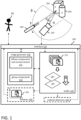
- FIG. 1 illustrates a simplified block diagram of an image processing computer system 100 according to an embodiment of the invention.
- FIG. 1 is explained in the context of FIG. 2 which is a simplified flow chart of a computer-implemented image processing method 1000 according to one embodiment of the invention for representation of one or more static objects in a digital target image.
- the following part of the description uses reference numbers which refer to FIG. 1 and to FIG. 2 .
- the terms "source” and “target” refer to pixels/images before and after processing.
- the computer system is communicatively coupled with a digital camera 210.
- the camera 210 is positioned at a location from where it can take digital images of one or more static objects 201, 202 under a constant viewing angle ⁇ (angle between the dashed straight lines evading from the camera).
- the objects are static in the sense that they do not move.
- the two static objects 201, 202 have surface elements a, b, c, d, e.
- Some of the surface elements may have different surface reflectance properties.
- the surface elements b, e may be wooden parts
- the surface elements a, c may be glass plates
- the surface element d may be an aluminum cylinder. Each of those materials has totally different reflectance properties.
- the static objects are illuminated by a light source 220.
- the light source 220 can have varying positions as illustrated by the dashed segment of a circle indicating the various light source positions associated with respective illumination angles ⁇ . Any other geometric shape allowing the light source to illuminate the static objects under different illumination angles may be used as well.
- each position of the light source on the circle segment corresponds to a particular illumination angle ⁇ .
- the light source 220 emits light to the surface element of the static object 201 under an illumination angle ⁇ 1 .
- the reflected light is received by the camera at a corresponding pixel under the viewing angle ⁇ 1 .
- the incident angle ⁇ 1 equals the angle of reflection ⁇ 1 .
- the light source may be moved from left to right on the dashed circle segment with stops appropriate for the camera 210 to take an image of the static objects under the respective illumination angle.
- the light source may be a remote flash light communicatively coupled with the camera 210 so that the illumination of the static objects is synchronized with the exposure time of the camera.
- the light source remains at a fixed location.
- the camera may take between 10 and 100 images wherein each image is recorded under a different illumination angle.
- the plurality of recorded camera images are then received 1100 by an interface component 110 of the system 100 as a plurality 211 of digital source images (of the static objects 201, 202).
- Each source image of the plurality 211 represents the static objects under the constant viewing angle ⁇ and under a different illumination angle ⁇ (different light source positions).
- the images have pixel sub-sets of source pixels that represent the surface elements a, b, c, d and e.
- the interface component 110 may also provide standard input/output means (e.g., display means and data input means) for a user 10 to interact with the system 100.
- standard input/output means e.g., display means and data input means
- the computer system 100 further has an image generator 130 for generating image data which is suitable for rendering a digital target image 141 including a plurality of target pixels.
- the image generator 130 includes two main functions: a diffuse components and normalized vector function 131 and a glossy components function 132.
- the diffuse components and normalized vector function 131 computes 1200 diffuse components DC for target pixels of one or more surface elements a, b, c, d, e by computing for each target pixel of the one or more surface elements a set of diffuse reflection coefficients from a best-fit function (reflection model) when fitted into reflected light intensity values of corresponding source pixels of the source images under different illumination angles.
- a best-fit function e.g., algebraic or geometric best-fit function such as, for example, second or higher order polynomial function, conic section function, trigonometric function, Gaussian function, Lorentzian function, or Voigt function may be used.
- the normal vectors NV can be generated 1300 for the target pixels of the one or more surface elements a, b, c, d, e by using the computed diffuse reflection coefficients p i x y , i : 1,..., n wherein the normal vectors NV describe the spatial orientations of the one or more surface elements.
- N ⁇ l u 0 l v 0 1 ⁇ l u 0 2 ⁇ l v 0 2 .
- the glossy components function 132 can then determine 1400 glossy coefficients for the target pixels of the one or more surface elements as the distances between the corresponding best-fit function values and the reflected light intensity values of the corresponding source pixels for the different illumination angles, and generates glossy components GC for the target pixels of the one or more surface elements a, b, c, d, e by overlaying a computer graphics reflection model in accordance with the corresponding normal vectors and the determined glossy coefficients.
- This function has values between 0 and 1 on all the pixels and is used as a glossy coefficient.
- the f G (x, y) coefficient varies between 0 and 1.
- the optional rendering component 140 can render 1600 the target image 141 with the computed diffuse components DC and glossy components GC for the constant viewing angle ⁇ and a first illumination angle.
- the rendered image can be visualized to a user 10 of the system 100 through the interface 110 via appropriate presentation means (e.g., a display device).
- appropriate presentation means e.g., a display device.
- the interface 110 is shown as a single component it may provide multiple interfaces for different purposes where a communication with external entities is required.
- the rendering component 140 may also be implemented in a further system which is communicatively coupled with the system 100.
- the rendering component can also re-render 1700 the target image 141 with the computed diffuse components and glossy components for the constant viewing angle ⁇ for a second illumination angle. This includes re-rendering the target image for an arbitrary illumination angle because the best-fit function provides a continuum of values for any illumination angle in the range of the best-fit function.
- the rendering component 140 may also switch to rendering a target image for this further viewing angle.
- a mobile computing device e.g., smartphone, tablet computer, etc.
- the user 10 can use the user interface functions of the mobile device to interact with the system 100.
- the inclination angle of the mobile device may be determined by the orientation sensor(s) and first and second or further illumination angles can be derived from first and second or further sensor data from the one or more orientation sensors.
- Automatic re-rendering of the target image can be triggered when the user generates corresponding illumination angle inputs for the rendering component 140 by moving the mobile device accordingly. Thereby, there is no need that the inclination angle of the mobile device corresponds to the actual illumination angle. For example, the user may hold the mobile device in a horizontal position and move the edges of the device up and down. The respective sensor data can then be transformed into illumination angles which correspond to a situation where the static object was in a vertical position and the light source was moved around the object in a horizontal plane.
- the optional material detection component 150 can identify one or more different materials associated with the one or more surface elements a, b, c, d, e wherein similar visual appearance of a material is determined through similar reflectance properties. A detailed example is discussed in the context of FIGs. 4 to 6 .
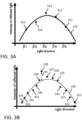
- FIG. 3A illustrates a best-fit function 310 for a diffuse surface reflection scenario, for a particular pixel.
- five source images of a static object are recorded at five different light source positions under five different illumination angles (illustrated by the light direction representations ⁇ 1 to ⁇ 5 ).
- the intensity of the light reflected by the static object as detected by the camera is illustrated by the bullets 311 to 315.
- the best-fit function 310 which represents the diffuse reflectance properties of the reflecting static object at the given pixel is fitted into the measured intensity values 311 to 315.
- the distances of the measured intensity values 311 to 315 to the best-fit function in this scenario are insignificant and can be considered to within the expected error tolerances.
- the system recognizes that the surface element which is represented by the given pixel in the source images is a matte surface element whose reflectance properties can be well modeled by the diffuse reflectance model in the form of the best-fit function 310.
- FIG. 3B illustrates a best-fit function 320 for a glossy surface reflection scenario.
- fourteen source images of a static object are recorded at fourteen different light source positions under fourteen different illumination angles.
- the intensity of the light reflected by the static object as detected by the camera is illustrated by the bullets 321 to 334 for a particular pixel.
- the best-fit function 320 which represents the diffuse reflectance properties of the reflecting static object at the particular pixel is fitted into the measured intensity values 321 to 334.
- the distances of the measured intensity values 321 -327 and 329 - 334 to the best-fit function in this scenario are insignificant and can be considered to within the expected error tolerances.
- the intensity value 328 has a significant distance d1 from the best-fit function 320 which indicates that for the corresponding illumination angle a reflection condition is fulfilled by the reflecting surface element of the static object.
- the angle of incidence is equal to the angle of reflection (cf. FIG. 1 , ⁇ 1 , ⁇ 1 ) which leads to the significant increase in the intensity of the reflected light if the surface element has a reflecting surface and not a matte surface.
- the system recognizes that the surface element which is represented by the particular pixel in the fourteen source images is a glossy surface element whose reflectance properties cannot be appropriately modeled by the diffuse reflectance model in the form of the best-fit function 320.
- the information that for the intensity value 328 the illumination angle (incident angle) equals the angle of reflection (which is correlated with the viewing angle of the camera) can be used by the normal vector function of the image generator to determine the normal vector associated with the reflecting surface element for determining the spatial orientation of the reflecting surface element as disclosed earlier.
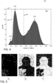
- FIG. 4 is a histogram 400 for identifying material filtering threshold values 401, 402 from source images according to one embodiment of the invention.
- any color channel of the original RGB signal may be used because it is assumed that the luminance value is independent of the color channel.
- the mean value is determined by adding the L values for a particular pixel across all source images and dividing the sum by a normalization factor. Then, the number of pixels having the same mean L values is counted. This count is then entered into the histogram for the respective mean L values.
- three peaks 410, 420, 430 can be identified in the histogram 400. Each peak represents a particular reflectance property of the surface elements appearing on the source images. That is, the respective surface elements of the static objects have different surface properties indicating different materials.
- the material detection component can then determine material filtering threshold values 401, 402 from the histogram 400 as the minima of the histogram. For example, mean L values below or equal the first material filtering threshold value 401(first filtering range) relate to a material associated with the peak 410. Mean L values above the first material filtering threshold value 401 and below or equal to the second material filtering threshold value 402 (second filtering range) relate to a material associated with the peak 420. Mean L values above the second material filtering threshold value 402 (third filtering range) relate to a material associated with the peak 430.
- the material detection component cannot determine the various types of material without an additional corresponding mapping between mean L values and the respective material types it can distinguish between different materials on the basis of the determined filtering ranges.
- FIG. 5 illustrates three images A, B, C with different material filtering threshold values applied.
- Image A illustrates the result of applying the first filtering range to an image of a mosaic wherein the different elements of the mosaic include different materials with different reflectance properties.
- the filtering function performed by the material detection component sets the pixel values of all pixels having a mean L value within the first filtering range to WHITE. Pixels with mean L values outside the first filtering range are set to BLACK. Any other pair of colors (or gray scale) may be used instead.
- the white pixels indicate the positions of mosaic elements with a corresponding first material type.
- Image B shows the result after the application of the second filtering range. That is, mosaic elements made of a material which corresponds to mean L values within the second filtering range are shown as WHITE pixels, whereas pixels with mean L values outside the second filtering range are shown as BLACK pixels.
- Image C shows the result after the application of the third filtering range. That is, mosaic elements made of a material which corresponds to mean L values within the third filtering range are shown as WHITE pixels, whereas pixels with mean L values outside the third filtering range are shown as BLACK pixels.
- each filtering range can be mapped to a corresponding visualization color for the respective material. That is, in the present scenario, three different colors (e.g., BLACK, WHITE, GRAY or RED, GREEN, BLUE or any other combination) would be used to visualize the three materials within a single image. For example, in this embodiment a user may get an overview in a single image of how many different materials are used within the mosaic. The previous embodiments, as shown in the images A,B, and C can then be activated as a drill down option when selecting any one of the materials (e.g., by clicking on a respective mosaic element.
- three different colors e.g., BLACK, WHITE, GRAY or RED, GREEN, BLUE or any other combination
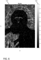
- FIG. 6 illustrates an image 610 with a filtering threshold scale 620 for representing the gloss contribution of pixels according to one embodiment of the invention.
- the filtering threshold scale 620 illustrates the continuous distribution of the parameter f G ( x,y ) representing the amount of gloss for each pixel in the mosaic image 610.
- a threshold value is selected which indicates that pixels with a mean L value below the selected threshold are treated as belonging to a glossy part of the image 610.
- all pixels having a mean L value above threshold 402 of FIG. 4 are set to 0.
- FIG. 6 illustrates how the glossy pixels are then visualized by the rendering component.
- FIG. 7 is a diagram that shows an example of a generic computer device 900 and a generic mobile computer device 950, which may be used with the techniques described here.
- Computing device 900 is intended to represent various forms of digital computers, such as laptops, desktops, workstations, personal digital assistants, servers, blade servers, mainframes, and other appropriate computers.
- Generic computer device may 900 implement the computer system 100 of FIG. 1 .
- Computing device 950 is intended to represent various forms of mobile devices, such as personal digital assistants, cellular telephones, smart phones, and other similar computing devices.
- computing device 950 may be a smartphone or tablet computer which is used to generate inputs for the rendering component with regards to the illumination angles based on orientation sensor values as disclosed previously.
- the components shown here, their connections and relationships, and their functions, are meant to be exemplary only, and are not meant to limit implementations of the inventions described and/or claimed in this document.
- Computing device 900 includes a processor 902, memory 904, a storage device 906, a high-speed interface 908 connecting to memory 904 and high-speed expansion ports 910, and a low speed interface 912 connecting to low speed bus 914 and storage device 906.
- Each of the components 902, 904, 906, 908, 910, and 912 are interconnected using various busses, and may be mounted on a common motherboard or in other manners as appropriate.
- the processor 902 can process instructions for execution within the computing device 900, including instructions stored in the memory 904 or on the storage device 906 to display graphical information for a GUI on an external input/output device, such as display 916 coupled to high speed interface 908.
- multiple processors and/or multiple buses may be used, as appropriate, along with multiple memories and types of memory.
- multiple computing devices 900 may be connected, with each device providing portions of the necessary operations (e.g., as a server bank, a group of blade servers, or a multi-processor system).
- the memory 904 stores information within the computing device 900.
- the memory 904 is a volatile memory unit or units.
- the memory 904 is a non-volatile memory unit or units.
- the memory 904 may also be another form of computer-readable medium, such as a magnetic or optical disk.
- the storage device 906 is capable of providing mass storage for the computing device 900.
- the storage device 906 may be or contain a computer-readable medium, such as a floppy disk device, a hard disk device, an optical disk device, or a tape device, a flash memory or other similar solid state memory device, or an array of devices, including devices in a storage area network or other configurations.
- a computer program product can be tangibly embodied in an information carrier.
- the computer program product may also contain instructions that, when executed, perform one or more methods, such as those described above.
- the information carrier is a computer- or machine-readable medium, such as the memory 904, the storage device 906, or memory on processor 902.
- the high speed controller 908 manages bandwidth-intensive operations for the computing device 900, while the low speed controller 912 manages lower bandwidth-intensive operations.
- the high-speed controller 908 is coupled to memory 904, display 916 (e.g., through a graphics processor or accelerator), and to high-speed expansion ports 910, which may accept various expansion cards (not shown).
- low-speed controller 912 is coupled to storage device 906 and low-speed expansion port 914.
- the low-speed expansion port which may include various communication ports (e.g., USB, Bluetooth, Ethernet, wireless Ethernet) may be coupled to one or more input/output devices, such as a keyboard, a pointing device, a scanner, or a networking device such as a switch or router, e.g., through a network adapter.
- input/output devices such as a keyboard, a pointing device, a scanner, or a networking device such as a switch or router, e.g., through a network adapter.
- the computing device 900 may be implemented in a number of different forms, as shown in the figure. For example, it may be implemented as a standard server 920, or multiple times in a group of such servers. It may also be implemented as part of a rack server system 924. In addition, it may be implemented in a personal computer such as a laptop computer 922. Alternatively, components from computing device 900 may be combined with other components in a mobile device (not shown), such as device 950. Each of such devices may contain one or more of computing device 900, 950, and an entire system may be made up of multiple computing devices 900, 950 communicating with each other.
- Computing device 950 includes a processor 952, memory 964, an input/output device such as a display 954, a communication interface 966, and a transceiver 968, among other components.
- the device 950 may also be provided with a storage device, such as a microdrive or other device, to provide additional storage.
- a storage device such as a microdrive or other device, to provide additional storage.
- Each of the components 950, 952, 964, 954, 966, and 968 are interconnected using various buses, and several of the components may be mounted on a common motherboard or in other manners as appropriate.
- the processor 952 can execute instructions within the computing device 950, including instructions stored in the memory 964.
- the processor may be implemented as a chipset of chips that include separate and multiple analog and digital processors.
- the processor may provide, for example, for coordination of the other components of the device 950, such as control of user interfaces, applications run by device 950, and wireless communication by device 950.
- Processor 952 may communicate with a user through control interface 958 and display interface 956 coupled to a display 954.
- the display 954 may be, for example, a TFT LCD (Thin-Film-Transistor Liquid Crystal Display) or an OLED (Organic Light Emitting Diode) display, or other appropriate display technology.
- the display interface 956 may comprise appropriate circuitry for driving the display 954 to present graphical and other information to a user.
- the control interface 958 may receive commands from a user and convert them for submission to the processor 952.
- an external interface 962 may be provide in communication with processor 952, so as to enable near area communication of device 950 with other devices.
- External interface 962 may provide, for example, for wired communication in some implementations, or for wireless communication in other implementations, and multiple interfaces may also be used.
- the memory 964 stores information within the computing device 950.
- the memory 964 can be implemented as one or more of a computer-readable medium or media, a volatile memory unit or units, or a non-volatile memory unit or units.
- Expansion memory 984 may also be provided and connected to device 950 through expansion interface 982, which may include, for example, a SIMM (Single In Line Memory Module) card interface.
- SIMM Single In Line Memory Module
- expansion memory 984 may provide extra storage space for device 950, or may also store applications or other information for device 950.
- expansion memory 984 may include instructions to carry out or supplement the processes described above, and may include secure information also.
- expansion memory 984 may act as a security module for device 950, and may be programmed with instructions that permit secure use of device 950.
- secure applications may be provided via the SIMM cards, along with additional information, such as placing the identifying information on the SIMM card in a non-hackable manner.
- the memory may include, for example, flash memory and/or NVRAM memory, as discussed below.
- a computer program product is tangibly embodied in an information carrier.
- the computer program product contains instructions that, when executed, perform one or more methods, such as those described above.
- the information carrier is a computer- or machine-readable medium, such as the memory 964, expansion memory 984, or memory on processor 952, that may be received, for example, over transceiver 968 or external interface 962.
- Device 950 may communicate wirelessly through communication interface 966, which may include digital signal processing circuitry where necessary. Communication interface 966 may provide for communications under various modes or protocols, such as GSM voice calls, SMS, EMS, or MMS messaging, CDMA, TDMA, PDC, WCDMA, CDMA2000, or GPRS, among others. Such communication may occur, for example, through radio-frequency transceiver 968. In addition, short-range communication may occur, such as using a Bluetooth, WiFi, or other such transceiver (not shown). In addition, GPS (Global Positioning System) receiver module 980 may provide additional navigation- and location-related wireless data to device 950, which may be used as appropriate by applications running on device 950.
- GPS Global Positioning System
- Device 950 may also communicate audibly using audio codec 960, which may receive spoken information from a user and convert it to usable digital information. Audio codec 960 may likewise generate audible sound for a user, such as through a speaker, e.g., in a handset of device 950. Such sound may include sound from voice telephone calls, may include recorded sound (e.g., voice messages, music files, etc.) and may also include sound generated by applications operating on device 950.
- Audio codec 960 may receive spoken information from a user and convert it to usable digital information. Audio codec 960 may likewise generate audible sound for a user, such as through a speaker, e.g., in a handset of device 950. Such sound may include sound from voice telephone calls, may include recorded sound (e.g., voice messages, music files, etc.) and may also include sound generated by applications operating on device 950.
- the computing device 950 may be implemented in a number of different forms, as shown in the figure. For example, it may be implemented as a cellular telephone 980. It may also be implemented as part of a smart phone 982, personal digital assistant, or other similar mobile device.
- implementations of the systems and techniques described here can be realized in digital electronic circuitry, integrated circuitry, specially designed ASICs (application specific integrated circuits), computer hardware, firmware, software, and/or combinations thereof.
- ASICs application specific integrated circuits
- These various implementations can include implementation in one or more computer programs that are executable and/or interpretable on a programmable system including at least one programmable processor, which may be special or general purpose, coupled to receive data and instructions from, and to transmit data and instructions to, a storage system, at least one input device, and at least one output device.
- the systems and techniques described here can be implemented on a computer having a display device (e.g., a CRT (cathode ray tube) or LCD (liquid crystal display) monitor) for displaying information to the user and a keyboard and a pointing device (e.g., a mouse or a trackball) by which the user can provide input to the computer.
- a display device e.g., a CRT (cathode ray tube) or LCD (liquid crystal display) monitor
- a keyboard and a pointing device e.g., a mouse or a trackball
- Other kinds of devices can be used to provide for interaction with a user as well; for example, feedback provided to the user can be any form of sensory feedback (e.g., visual feedback, auditory feedback, or tactile feedback); and input from the user can be received in any form, including acoustic, speech, or tactile input.
- the systems and techniques described here can be implemented in a computing device that includes a back end component (e.g., as a data server), or that includes a middleware component (e.g., an application server), or that includes a front end component (e.g., a client computer having a graphical user interface or a Web browser through which a user can interact with an implementation of the systems and techniques described here), or any combination of such back end, middleware, or front end components.
- the components of the system can be interconnected by any form or medium of digital data communication (e.g., a communication network). Examples of communication networks include a local area network ("LAN”), a wide area network (“WAN”), and the Internet.
- LAN local area network
- WAN wide area network
- the Internet the global information network
- the computing device can include clients and servers.
- a client and server are generally remote from each other and typically interact through a communication network.
- the relationship of client and server arises by virtue of computer programs running on the respective computers and having a client-server relationship to each other.
- the client could provide the optional renderer for rendering the target image whereas the other components of the system 100 (cf. FIG. 1 ) may be implemented on a server.
Landscapes
- Engineering & Computer Science (AREA)
- Computer Graphics (AREA)
- Physics & Mathematics (AREA)
- General Physics & Mathematics (AREA)
- Theoretical Computer Science (AREA)
- Image Generation (AREA)
- Image Processing (AREA)
- Investigating Or Analysing Materials By Optical Means (AREA)
Description
- The present invention generally relates to electronic data processing, and more particularly, relates to methods, computer program products and systems for digital image processing.
- Photography in the analog as well as in the digital world allows for the representation of physical objects and their visual appearance. However, photography, including digital photography, has some drawbacks. Photography is not able to visualize dynamic interaction of light with surfaces, since it is a static method to capture light reflection of materials and objects. For example, this may be disadvantageous for the representation or documentation of any kind of surface structure, be it art-works, objects in forensics, dermatology, archaeology or for high quality product visualization (e.g., for promoting products). A prior art approach to overcome such drawbacks is Reflectance Transformation Imaging (RTI - cf., M. Mudge et al. Image-Based Empirical Information Acquisition, Scientific Reliability, and Long-Term Digital Preservation for the Natural Sciences and Cultural Heritage, Eurographics. (2008); M. Mudge, et al. Principles and Practices of Robust, Photography-based Digital Imaging Techniques for Museums. 11th VAST International Symposium on Virtual Reality, Archaeology and Cultural Heritage, (pp. 111-137). (2010)).
- RTI is a set of computational photographic methods that capture a subject's surface shape and color and enables the interactive re-lighting of the subject from any direction based on a mathematical model. Polynomial Texture Mapping (PTM) describes the prior art approach (cf., T. Malzbender, D. Gelb, and H. Wolters. Polynomial texture maps. Proceedings of the 28th annual conference on Computer graphics and interactive techniques (pp. 519-528). (2001)). The reflection of light is, in a first step, captured by multiple photo images, where objects are illuminated by a light source from different positions (under different illumination angles). For example, the light source may be a flash light (or a LED light) which is synchronized with the digital camera to illuminate the static objects when a digital (source) image is recorded. In a second step, a polynomial of second order is fitted to the measured reflection for each pixel position. However, PTM has limitations of the mathematical model that is applied. A second order polynomial is able to reproduce reflection of diffuse (matte) surfaces, also called Lambertian surfaces, but reproduction of gloss is not possible.
- The publication "Robust estimation of surface properties and interpolation of shadow/specularity components" by Drew et al. in Image and Vision Computing Volume 30, Issues 4-5, May 2012, Pages 317-331, discloses a Polynomial Texture Map based modeling approach for recovering surface properties using a simple radial basis function interpolation to interpolate specularities as well as attached and cast shadows, with no need for reflectance sharing across pixels or extremely large numbers of interpolation coefficients. The publication "Digital Materiality with Enhanced Reflectance Transformation Imaging" by Fornaro et al. published in Archiving Conference, Volume: 13 | Article ID: art00004, April 2016 discloses an approach for composing the visual appearance of a realistic surface by generating the glossy component based on a shading model derived from computer graphics. A virtual specularity is added based on a shading model.
- There is therefore a need for an approach to improve the prior art approaches in that reproduction of gloss is enabled for photographic representation of objects with glossy surface elements.
- A Lambertian surface scatters the incoming light in such a way that the apparent brightness does not depend on the observer's point of view. Although the radiance of the surface depends on the angle between the normal and the illuminating light source, following the Lambertian cosine law, it does not depend on the angle between the normal and the observer: it has a uniform reflection (e.g., like a matte surface). Differently, a glossy surface has a component of specular reflection. Specularity means, that light is reflected only in one direction, defined by the law of reflection (also called Snell law), a mirror shows a perfect specular reflection (cf. M. Born, and E. Wold. Principles of Optics. Electromagnetic Theory of Propagation, Interference and Diffraction of Light. 6th Edition. Pergamon Press. (1989)). The limitation of the PTM second order polynomial for the reproduction of objects that are made of one single or multiple materials needs to be overcome. An object surface element interacts with light and in most cases diffuse and glossy materials constitute the object and give it is characteristic look. In other words, one and the same object may have surface elements made of diffuse materials and may also have surface elements made of glossy materials.
- The above technical problem is solved by an image processing method, a corresponding computer program product to be executed by a computer system to perform the image processing method, and by a computer system according to the independent claims.
- In one embodiment, an image processing computer system is provided for rendering one or more static object representations (i.e. representations of one or more static objects) in a digital target image including a plurality of target pixels. The digital target image is the result of the image processing method which is executed by the computer system by processing a plurality of source images. The one or more static objects have surface elements with different surface reflectance properties. The static objects are real world physical objects whose visible surface elements may be composed of different materials (e.g., glass, wood, stone, etc.) having different reflectance properties.
- The system has an interface component to receive the plurality of digital source images of the one or more static objects wherein each source image of the plurality represents the one or more static objects under a constant viewing angle and under a different illumination angle. For example, a digital camera may be located a fixed position. The camera is directed to the static object(s) under a constant viewing angle. The static object(s) are illuminated by a light source (advantageously a directed light source). For each source image the light source is moved to a different position so that each source image is recorded under a different illumination angle.
- The system further has an image generator component to perform the computation steps required to arrive at the improved target image. The computation tasks are performed by one or more processor components of the systems. In a first step, the image generator computes diffuse components for target pixels of one or more surface elements by computing for each target pixel of the one or more surface elements a set of diffuse reflection coefficients from a best-fit function when fitted into reflected light intensity values of corresponding source pixels of the source images under different illumination angles. In the PTM approach this step is performed with a second order polynomial as the best-fit function. However, any other appropriate mathematical best-fit function may be used instead, such as for example, an algebraic or geometric best-fit function selected from the group of: higher order polynomial function, conic section function, trigonometric function, Gaussian function, Lorentzian function, Voigt function, or any other potential best-fit function known by a person skilled in the art.
- In a second step, the image generator generates normal vectors for the target pixels of the one or more surface elements by using the computed diffuse reflection coefficients. The normal vectors describe the spatial orientations of the one or more surface elements. In other words, the image generator determines for each pixel of a corresponding particular surface element an orientation vector (normal vector) which is orthogonal to a plane of the surface element in each respective pixel.
- In a third step, the image generator determines glossy coefficients for the target pixels of the one or more surface elements as the distances (i.e., value differences) between the corresponding best-fit function values and the reflected light intensity values of the corresponding source pixels for the different illumination angles. In other words, a distance between a particular reflected light intensity value for a particular pixel position and the respective best-fit function value indicates that the model for the diffuse components derived from the source images is inaccurate for the particular pixel position. The distance from the best-fit function value can be seen as an indicator for gloss which is present at the particular pixel position.
- In a fourth step, the image process generates glossy components for the target pixels of the one or more surface elements by overlaying a computer graphics shading and reflection model in accordance with the corresponding normal vectors and the determined glossy coefficients. Such reflection models are known in the art of computer graphics and various reflection models may be used to compute gloss. Examples of reflection models include the Phong reflection model, Cook-Torrance model, Ward anisotropic model, and Gaussian models.
- After this step, the image processing method provides the information for rendering a particular target image. It is to be noted that the target image can be rendered for any illumination angle because the diffuse and glossy components are models providing pixel values for the target image for a continuum of illumination angles although the original source images provided pixel values only for a plurality of discrete illumination angles under which the respective source images were recorded.
- The system typically has a rendering component configured to render the target image with the computed diffuse components and glossy components for the constant viewing angle and a first illumination angle. For example, the solution can be implemented with the commonly known graphics libraries, openGL or WebGL (provided by Khronos Group, Beaverton, USA) to render RTI images in any web-browser. A web-based solution opens various new applications and the possibility for collaborative work.
- The rendering component further may re-render the target image with the computed diffuse components and glossy components for the constant viewing angle and a second (or further) illumination angle(s). That is, target image can be visualized for any illumination angle from the continuum of illumination angels associated with the diffuse/glossy component models.
- In one embodiment, a mobile computing device (e.g., a smartphone or a tablet computer) can be used to implement and run the previously disclosed image processing system. The mobile device may include one or more orientation sensors (e.g., gravity sensor, acceleration sensor, gyroscope, etc.). For example, a user of the mobile device may now move (tilt or incline) the mobile device so that the orientation sensor(s) provide sensor data reflecting the current orientation of the mobile device. The mobile device can then derive the first and second illumination angles from first and second sensor data from the one or more orientation sensors wherein the first and second sensor data is associated with first and second orientations of the mobile computing device, respectively. In other words, a user inclining the display can initiate the generating of orientation sensor data in response to his movements which is then used as a trigger for re-rendering the target image for respective illumination angles mapped to the sensor data.
- In one embodiment, the system further includes a material detection component configured to identify one or more different materials associated with the one or more surface elements wherein similar visual appearance of a material is determined through similar reflectance properties.
- In one embodiment, a computer-implemented image processing method is provided for representation of one or more static objects in a digital target image. The method includes the steps: receiving a plurality of digital source images of the one or more static objects wherein each source image of the plurality represents the one or more static objects under a constant viewing angle and under a different illumination angle; computing diffuse components for target pixels of one or more surface elements by computing for each target pixel of the one or more surface elements a set of diffuse reflection coefficients from a best-fit function when fitted into reflected light intensity values of corresponding source pixels of the source images under different illumination angles; generating normal vectors for the target pixels of the one or more surface elements by using the computed diffuse reflection coefficients wherein the normal vectors describe the spatial orientations of the one or more surface elements; determining glossy coefficients for the target pixels of the one or more surface elements as the distances between the corresponding best-fit function values and the reflected light intensity values of the corresponding source pixels for the different illumination angles; and generating glossy components for the target pixels of the one or more surface elements by overlaying a computer graphics reflection model in accordance with the corresponding normal vectors and the determined glossy coefficients.
- The method provides the diffuse and glossy components for the target pixels of the target picture which can then be assembled into a particular target picture for an arbitrary illumination angle within the range of illumination angles supported by the best-fit function values on the basis of the original source images.
- The method may further include the optional step rendering the target image with the computed diffuse components and glossy components for the constant viewing angle and a first illumination angle.
- The method may further include the optional step re-rendering the target image with the computed diffuse components and glossy components for the constant viewing angle and a second illumination angle. Thereby, rendering and re-rendering may be performed by a mobile computing device having one or more orientation sensors. The first and second illumination angles can be derived from first and second sensor data from the one or more orientation sensors wherein the first and second sensor data is associated with first and second orientations of the mobile computing device, respectively.
- The method may be iteratively repeated for at least one further constant viewing angle. For example, the plurality of source images may include a first set of source images associated with a first constant viewing angle and a second of further set of source images associated with a second or further viewing angles. In this embodiment it is possible to virtually move around the static object(s) by switching from a target image rendered for the first viewing angle to a target image rendered for the second (or further) viewing angles.
- In one embodiment, generating glossy components is performed only for target pixels with glossy coefficients exceeding a predefined threshold value. In other words, the predefined threshold functions as a filter to eliminate gloss components which may result from errors in the original source images. Distances of the light reflection intensity from the respective best-fit function values which are below the predefined threshold may be perceived as such errors which can be suppressed by the threshold filter function.
- In one embodiment, the method further includes receiving modified reflection parameters for the reflection model wherein the modified parameters represent the surface reflectance properties of the surface elements. For example, a user may enter such modified reflection parameters to further improve the target picture with regards to the gloss effects. In some cases, a target image may become less realistic compared to the real world situation of the static objects but it may be perceived more aesthetic by a human observer.
- In one embodiment, the method further includes identifying one or more different materials associated with the one or more surface elements wherein similar visual appearance of a material is determined through similar reflectance properties. In other words, the image processing method can identify surface elements in the target image which show similar reflectance properties and classify such surface elements as similar materials.
- In one embodiment, a computer program product includes a set of instructions that when loaded into a memory of a computing device and executed by at least one processor of the computing device execute the steps of the above computer-implemented image processing method.
- Further aspects of the invention will be realized and attained by means of the elements and combinations particularly depicted in the appended claims. It is to be understood that both, the foregoing general description and the following detailed description are exemplary and explanatory only and are not restrictive of the invention as described.
-
-
FIG. 1 is a simplified block diagram showing an image processing computer system according to an embodiment of the invention for generating a digital target image from a plurality of source images received from a digital camera; -
FIG. 2 is a simplified flow chart of a computer-implemented image processing method according to one embodiment of the invention for representation of one or more static objects in a digital target image; -
FIG. 3A illustrates a best-fit function for a diffuse surface reflection scenario; -
FIG. 3B illustrates a best-fit function for a glossy surface reflection scenario; -
FIG. 4 is a histogram for identifying material filtering threshold values from source images according to one embodiment of the invention; -
FIG. 5 illustrates three images with different material filtering threshold values applied; -
FIG. 6 illustrates an image with a filtering threshold scale for representing the gloss contribution of pixels according to one embodiment of the invention; and -
FIG. 7 is a diagram that shows an example of a generic computer device and a generic mobile computer device, which may be used with the techniques described here. -
FIG. 1 illustrates a simplified block diagram of an imageprocessing computer system 100 according to an embodiment of the invention.FIG. 1 is explained in the context ofFIG. 2 which is a simplified flow chart of a computer-implementedimage processing method 1000 according to one embodiment of the invention for representation of one or more static objects in a digital target image. The following part of the description uses reference numbers which refer toFIG. 1 and toFIG. 2 . The terms "source" and "target" refer to pixels/images before and after processing. - The computer system is communicatively coupled with a
digital camera 210. Thecamera 210 is positioned at a location from where it can take digital images of one or morestatic objects static objects light source 220. Thelight source 220 can have varying positions as illustrated by the dashed segment of a circle indicating the various light source positions associated with respective illumination angles β. Any other geometric shape allowing the light source to illuminate the static objects under different illumination angles may be used as well. In the example, each position of the light source on the circle segment corresponds to a particular illumination angle β. At the current position, thelight source 220 emits light to the surface element of thestatic object 201 under an illumination angle β1. The reflected light is received by the camera at a corresponding pixel under the viewing angle α1. In this case, the incident angle β1 equals the angle of reflection α1. For example, the light source may be moved from left to right on the dashed circle segment with stops appropriate for thecamera 210 to take an image of the static objects under the respective illumination angle. For example, the light source may be a remote flash light communicatively coupled with thecamera 210 so that the illumination of the static objects is synchronized with the exposure time of the camera. In other words, during the exposure time for taking a particular source image, the light source remains at a fixed location. For example, the camera may take between 10 and 100 images wherein each image is recorded under a different illumination angle. - The plurality of recorded camera images are then received 1100 by an
interface component 110 of thesystem 100 as aplurality 211 of digital source images (of thestatic objects 201, 202). Each source image of theplurality 211 represents the static objects under the constant viewing angle α and under a different illumination angle β (different light source positions). As illustrated, the images have pixel sub-sets of source pixels that represent the surface elements a, b, c, d and e. - The
interface component 110 may also provide standard input/output means (e.g., display means and data input means) for auser 10 to interact with thesystem 100. - The
computer system 100 further has animage generator 130 for generating image data which is suitable for rendering adigital target image 141 including a plurality of target pixels. Theimage generator 130 includes two main functions: a diffuse components and normalizedvector function 131 and a glossy components function 132. - The diffuse components and normalized
vector function 131 computes 1200 diffuse components DC for target pixels of one or more surface elements a, b, c, d, e by computing for each target pixel of the one or more surface elements a set of diffuse reflection coefficients from a best-fit function (reflection model) when fitted into reflected light intensity values of corresponding source pixels of the source images under different illumination angles. Any appropriate mathematical best-fit function, e.g., algebraic or geometric best-fit function such as, for example, second or higher order polynomial function, conic section function, trigonometric function, Gaussian function, Lorentzian function, or Voigt function may be used. For example, to estimate the diffuse components of the surface elements the following two dimensional function (fmatte) can be used:


computer system 100 when generating the target image from the source images because the computational effort is lower compared to a three-dimensional model. Interpolating the best-fit function for arbitrary 3-D light direction is very expensive in terms of memory and computational power. The reduction to a two-dimensional reflection model is possible when assuming that the light source is always at the same distance to the static objects. That is, the light source is moved along a circle with the static object(s) being at the center of the circle. This assumption holds if the circle, where the light source moves, is big enough compared to the object acquired. Experiments show that advantageously, the circle radius is approximately two or more times the object dimensions. - To estimate the diffuse characteristics of matte surface elements, only the fitted parameters are used and the coordinates of the normal vectors indicating the orientation of the surface elements at the respective pixel positions are obtained 1300 as a by-product of the diffuse component computation.
- In more detail, the normal vectors NV can be generated 1300 for the target pixels of the one or more surface elements a, b, c, d, e by using the computed diffuse reflection coefficients


- The glossy components function 132 can then determine 1400 glossy coefficients for the target pixels of the one or more surface elements as the distances between the corresponding best-fit function values and the reflected light intensity values of the corresponding source pixels for the different illumination angles, and generates glossy components GC for the target pixels of the one or more surface elements a, b, c, d, e by overlaying a computer graphics reflection model in accordance with the corresponding normal vectors and the determined glossy coefficients.
- For each pixel a set of n coefficients is obtained. The distance between the fmatte best-fit function value and the intensity of the pixel for all illumination angles is computed for each target pixel. To do so a function is defined


- A specific cut is made using the values of the mean value of the intensity:


- The
optional rendering component 140 can render 1600 thetarget image 141 with the computed diffuse components DC and glossy components GC for the constant viewing angle α and a first illumination angle. The rendered image can be visualized to auser 10 of thesystem 100 through theinterface 110 via appropriate presentation means (e.g., a display device). Although theinterface 110 is shown as a single component it may provide multiple interfaces for different purposes where a communication with external entities is required. Alternatively, therendering component 140 may also be implemented in a further system which is communicatively coupled with thesystem 100. The rendering component can also re-render 1700 thetarget image 141 with the computed diffuse components and glossy components for the constant viewing angle α for a second illumination angle. This includes re-rendering the target image for an arbitrary illumination angle because the best-fit function provides a continuum of values for any illumination angle in the range of the best-fit function. - If the received source images include a subset of images for a further viewing angle which are processed by the
image generator 130 accordingly, therendering component 140 may also switch to rendering a target image for this further viewing angle. In one embodiment, a mobile computing device (e.g., smartphone, tablet computer, etc.) which includes one or more orientation sensors may be used to run thesystem 100. In this case, theuser 10 can use the user interface functions of the mobile device to interact with thesystem 100. For example, the inclination angle of the mobile device may be determined by the orientation sensor(s) and first and second or further illumination angles can be derived from first and second or further sensor data from the one or more orientation sensors. Automatic re-rendering of the target image can be triggered when the user generates corresponding illumination angle inputs for therendering component 140 by moving the mobile device accordingly. Thereby, there is no need that the inclination angle of the mobile device corresponds to the actual illumination angle. For example, the user may hold the mobile device in a horizontal position and move the edges of the device up and down. The respective sensor data can then be transformed into illumination angles which correspond to a situation where the static object was in a vertical position and the light source was moved around the object in a horizontal plane. - The optional
material detection component 150 can identify one or more different materials associated with the one or more surface elements a, b, c, d, e wherein similar visual appearance of a material is determined through similar reflectance properties. A detailed example is discussed in the context ofFIGs. 4 to 6 . -
FIG. 3A illustrates a best-fit function 310 for a diffuse surface reflection scenario, for a particular pixel. In this example, five source images of a static object are recorded at five different light source positions under five different illumination angles (illustrated by the light direction representations β 1 to β 5). The intensity of the light reflected by the static object as detected by the camera is illustrated by thebullets 311 to 315. The best-fit function 310 which represents the diffuse reflectance properties of the reflecting static object at the given pixel is fitted into the measured intensity values 311 to 315. The distances of the measured intensity values 311 to 315 to the best-fit function in this scenario are insignificant and can be considered to within the expected error tolerances. As a conclusion, the system recognizes that the surface element which is represented by the given pixel in the source images is a matte surface element whose reflectance properties can be well modeled by the diffuse reflectance model in the form of the best-fit function 310. -
FIG. 3B illustrates a best-fit function 320 for a glossy surface reflection scenario. In this example, fourteen source images of a static object are recorded at fourteen different light source positions under fourteen different illumination angles. The intensity of the light reflected by the static object as detected by the camera is illustrated by thebullets 321 to 334 for a particular pixel. The best-fit function 320 which represents the diffuse reflectance properties of the reflecting static object at the particular pixel is fitted into the measured intensity values 321 to 334. The distances of the measured intensity values 321 -327 and 329 - 334 to the best-fit function in this scenario are insignificant and can be considered to within the expected error tolerances. However, theintensity value 328 has a significant distance d1 from the best-fit function 320 which indicates that for the corresponding illumination angle a reflection condition is fulfilled by the reflecting surface element of the static object. In other words, under this illumination angle the angle of incidence is equal to the angle of reflection (cf.FIG. 1 , β1, α1) which leads to the significant increase in the intensity of the reflected light if the surface element has a reflecting surface and not a matte surface. As a conclusion, the system recognizes that the surface element which is represented by the particular pixel in the fourteen source images is a glossy surface element whose reflectance properties cannot be appropriately modeled by the diffuse reflectance model in the form of the best-fit function 320. The information that for theintensity value 328 the illumination angle (incident angle) equals the angle of reflection (which is correlated with the viewing angle of the camera) can be used by the normal vector function of the image generator to determine the normal vector associated with the reflecting surface element for determining the spatial orientation of the reflecting surface element as disclosed earlier. -
FIG. 4 is ahistogram 400 for identifying material filtering threshold values 401, 402 from source images according to one embodiment of the invention. Thehistogram 400 may be generated by the material detection component by analyzing the pixels of the source images in the following way. For each pixel the material detection component determines a mean luminance value (mean L value). Looking at equation (8) shows that the mean value is normalized. Np is not just the number of points, but the number of points multiplied by the maximum value of L for a particular pixel. For example, if the pixel values are "1,5,6,7,8" Np is 8*5=40, and the meanvalue is 0.675. Alternatively, a fixed value for the maximum can be used. For example, the pixel value may be fixed between 1 and 10. In case the pixel values are "1,5,6,7,8", Np can be 10*8 and the meanvalue can be 0.3375. - For example, in case the light source provides white light, any color channel of the original RGB signal may be used because it is assumed that the luminance value is independent of the color channel. The mean value is determined by adding the L values for a particular pixel across all source images and dividing the sum by a normalization factor. Then, the number of pixels having the same mean L values is counted. This count is then entered into the histogram for the respective mean L values. In the example, three
peaks histogram 400. Each peak represents a particular reflectance property of the surface elements appearing on the source images. That is, the respective surface elements of the static objects have different surface properties indicating different materials. The material detection component can then determine material filtering threshold values 401, 402 from thehistogram 400 as the minima of the histogram. For example, mean L values below or equal the first material filtering threshold value 401(first filtering range) relate to a material associated with thepeak 410. Mean L values above the first materialfiltering threshold value 401 and below or equal to the second material filtering threshold value 402 (second filtering range) relate to a material associated with thepeak 420. Mean L values above the second material filtering threshold value 402 (third filtering range) relate to a material associated with thepeak 430. Although the material detection component cannot determine the various types of material without an additional corresponding mapping between mean L values and the respective material types it can distinguish between different materials on the basis of the determined filtering ranges. -
FIG. 5 illustrates three images A, B, C with different material filtering threshold values applied. Image A illustrates the result of applying the first filtering range to an image of a mosaic wherein the different elements of the mosaic include different materials with different reflectance properties. In the example, the filtering function performed by the material detection component sets the pixel values of all pixels having a mean L value within the first filtering range to WHITE. Pixels with mean L values outside the first filtering range are set to BLACK. Any other pair of colors (or gray scale) may be used instead. In other words, the white pixels indicate the positions of mosaic elements with a corresponding first material type. - Image B shows the result after the application of the second filtering range. That is, mosaic elements made of a material which corresponds to mean L values within the second filtering range are shown as WHITE pixels, whereas pixels with mean L values outside the second filtering range are shown as BLACK pixels.
- Image C shows the result after the application of the third filtering range. That is, mosaic elements made of a material which corresponds to mean L values within the third filtering range are shown as WHITE pixels, whereas pixels with mean L values outside the third filtering range are shown as BLACK pixels.
- In one embodiment, each filtering range can be mapped to a corresponding visualization color for the respective material. That is, in the present scenario, three different colors (e.g., BLACK, WHITE, GRAY or RED, GREEN, BLUE or any other combination) would be used to visualize the three materials within a single image. For example, in this embodiment a user may get an overview in a single image of how many different materials are used within the mosaic. The previous embodiments, as shown in the images A,B, and C can then be activated as a drill down option when selecting any one of the materials (e.g., by clicking on a respective mosaic element. The selection can then be used by the material detection component as an input to activate the corresponding binary filter function for the selected material and visualize all occurrences of the selected material in the image.
FIG. 6 illustrates animage 610 with afiltering threshold scale 620 for representing the gloss contribution of pixels according to one embodiment of the invention. Thefiltering threshold scale 620 illustrates the continuous distribution of the parameter fG (x,y) representing the amount of gloss for each pixel in themosaic image 610. In the example, a threshold value is selected which indicates that pixels with a mean L value below the selected threshold are treated as belonging to a glossy part of theimage 610. In theexample image 610, all pixels having a mean L value abovethreshold 402 ofFIG. 4 are set to 0. As a consequence, for such pixels the glossy coefficients are calculated with a result different from zero.FIG. 6 illustrates how the glossy pixels are then visualized by the rendering component. -
FIG. 7 is a diagram that shows an example of ageneric computer device 900 and a genericmobile computer device 950, which may be used with the techniques described here.Computing device 900 is intended to represent various forms of digital computers, such as laptops, desktops, workstations, personal digital assistants, servers, blade servers, mainframes, and other appropriate computers. Generic computer device may 900 implement thecomputer system 100 ofFIG. 1 .Computing device 950 is intended to represent various forms of mobile devices, such as personal digital assistants, cellular telephones, smart phones, and other similar computing devices. For example,computing device 950 may be a smartphone or tablet computer which is used to generate inputs for the rendering component with regards to the illumination angles based on orientation sensor values as disclosed previously. The components shown here, their connections and relationships, and their functions, are meant to be exemplary only, and are not meant to limit implementations of the inventions described and/or claimed in this document. -
Computing device 900 includes aprocessor 902,memory 904, astorage device 906, a high-speed interface 908 connecting tomemory 904 and high-speed expansion ports 910, and alow speed interface 912 connecting tolow speed bus 914 andstorage device 906. Each of thecomponents processor 902 can process instructions for execution within thecomputing device 900, including instructions stored in thememory 904 or on thestorage device 906 to display graphical information for a GUI on an external input/output device, such asdisplay 916 coupled tohigh speed interface 908. In other implementations, multiple processors and/or multiple buses may be used, as appropriate, along with multiple memories and types of memory. Also,multiple computing devices 900 may be connected, with each device providing portions of the necessary operations (e.g., as a server bank, a group of blade servers, or a multi-processor system). - The
memory 904 stores information within thecomputing device 900. In one implementation, thememory 904 is a volatile memory unit or units. In another implementation, thememory 904 is a non-volatile memory unit or units. Thememory 904 may also be another form of computer-readable medium, such as a magnetic or optical disk. - The
storage device 906 is capable of providing mass storage for thecomputing device 900. In one implementation, thestorage device 906 may be or contain a computer-readable medium, such as a floppy disk device, a hard disk device, an optical disk device, or a tape device, a flash memory or other similar solid state memory device, or an array of devices, including devices in a storage area network or other configurations. A computer program product can be tangibly embodied in an information carrier. The computer program product may also contain instructions that, when executed, perform one or more methods, such as those described above. The information carrier is a computer- or machine-readable medium, such as thememory 904, thestorage device 906, or memory onprocessor 902. - The
high speed controller 908 manages bandwidth-intensive operations for thecomputing device 900, while thelow speed controller 912 manages lower bandwidth-intensive operations. Such allocation of functions is exemplary only. In one implementation, the high-speed controller 908 is coupled tomemory 904, display 916 (e.g., through a graphics processor or accelerator), and to high-speed expansion ports 910, which may accept various expansion cards (not shown). In the implementation, low-speed controller 912 is coupled tostorage device 906 and low-speed expansion port 914. The low-speed expansion port, which may include various communication ports (e.g., USB, Bluetooth, Ethernet, wireless Ethernet) may be coupled to one or more input/output devices, such as a keyboard, a pointing device, a scanner, or a networking device such as a switch or router, e.g., through a network adapter. - The
computing device 900 may be implemented in a number of different forms, as shown in the figure. For example, it may be implemented as astandard server 920, or multiple times in a group of such servers. It may also be implemented as part of arack server system 924. In addition, it may be implemented in a personal computer such as alaptop computer 922. Alternatively, components fromcomputing device 900 may be combined with other components in a mobile device (not shown), such asdevice 950. Each of such devices may contain one or more ofcomputing device multiple computing devices -
Computing device 950 includes aprocessor 952,memory 964, an input/output device such as adisplay 954, acommunication interface 966, and atransceiver 968, among other components. Thedevice 950 may also be provided with a storage device, such as a microdrive or other device, to provide additional storage. Each of thecomponents - The
processor 952 can execute instructions within thecomputing device 950, including instructions stored in thememory 964. The processor may be implemented as a chipset of chips that include separate and multiple analog and digital processors. The processor may provide, for example, for coordination of the other components of thedevice 950, such as control of user interfaces, applications run bydevice 950, and wireless communication bydevice 950. -
Processor 952 may communicate with a user throughcontrol interface 958 anddisplay interface 956 coupled to adisplay 954. Thedisplay 954 may be, for example, a TFT LCD (Thin-Film-Transistor Liquid Crystal Display) or an OLED (Organic Light Emitting Diode) display, or other appropriate display technology. Thedisplay interface 956 may comprise appropriate circuitry for driving thedisplay 954 to present graphical and other information to a user. Thecontrol interface 958 may receive commands from a user and convert them for submission to theprocessor 952. In addition, anexternal interface 962 may be provide in communication withprocessor 952, so as to enable near area communication ofdevice 950 with other devices.External interface 962 may provide, for example, for wired communication in some implementations, or for wireless communication in other implementations, and multiple interfaces may also be used. - The
memory 964 stores information within thecomputing device 950. Thememory 964 can be implemented as one or more of a computer-readable medium or media, a volatile memory unit or units, or a non-volatile memory unit or units. Expansion memory 984 may also be provided and connected todevice 950 throughexpansion interface 982, which may include, for example, a SIMM (Single In Line Memory Module) card interface. Such expansion memory 984 may provide extra storage space fordevice 950, or may also store applications or other information fordevice 950. Specifically, expansion memory 984 may include instructions to carry out or supplement the processes described above, and may include secure information also. Thus, for example, expansion memory 984 may act as a security module fordevice 950, and may be programmed with instructions that permit secure use ofdevice 950. In addition, secure applications may be provided via the SIMM cards, along with additional information, such as placing the identifying information on the SIMM card in a non-hackable manner. - The memory may include, for example, flash memory and/or NVRAM memory, as discussed below. In one implementation, a computer program product is tangibly embodied in an information carrier. The computer program product contains instructions that, when executed, perform one or more methods, such as those described above. The information carrier is a computer- or machine-readable medium, such as the
memory 964, expansion memory 984, or memory onprocessor 952, that may be received, for example, overtransceiver 968 orexternal interface 962. -
Device 950 may communicate wirelessly throughcommunication interface 966, which may include digital signal processing circuitry where necessary.Communication interface 966 may provide for communications under various modes or protocols, such as GSM voice calls, SMS, EMS, or MMS messaging, CDMA, TDMA, PDC, WCDMA, CDMA2000, or GPRS, among others. Such communication may occur, for example, through radio-frequency transceiver 968. In addition, short-range communication may occur, such as using a Bluetooth, WiFi, or other such transceiver (not shown). In addition, GPS (Global Positioning System)receiver module 980 may provide additional navigation- and location-related wireless data todevice 950, which may be used as appropriate by applications running ondevice 950. -
Device 950 may also communicate audibly usingaudio codec 960, which may receive spoken information from a user and convert it to usable digital information.Audio codec 960 may likewise generate audible sound for a user, such as through a speaker, e.g., in a handset ofdevice 950. Such sound may include sound from voice telephone calls, may include recorded sound (e.g., voice messages, music files, etc.) and may also include sound generated by applications operating ondevice 950. - The
computing device 950 may be implemented in a number of different forms, as shown in the figure. For example, it may be implemented as acellular telephone 980. It may also be implemented as part of asmart phone 982, personal digital assistant, or other similar mobile device. - Various implementations of the systems and techniques described here can be realized in digital electronic circuitry, integrated circuitry, specially designed ASICs (application specific integrated circuits), computer hardware, firmware, software, and/or combinations thereof. These various implementations can include implementation in one or more computer programs that are executable and/or interpretable on a programmable system including at least one programmable processor, which may be special or general purpose, coupled to receive data and instructions from, and to transmit data and instructions to, a storage system, at least one input device, and at least one output device.
- These computer programs (also known as programs, software, software applications or code) include machine instructions for a programmable processor, and can be implemented in a high-level procedural and/or object-oriented programming language, and/or in assembly/machine language. As used herein, the terms "machine-readable medium" "computer-readable medium" refers to any computer program product, apparatus and/or device (e.g., magnetic discs, optical disks, memory, Programmable Logic Devices (PLDs)) used to provide machine instructions and/or data to a programmable processor, including a machine-readable medium that receives machine instructions as a machine-readable signal. The term "machine-readable signal" refers to any signal used to provide machine instructions and/or data to a programmable processor.
- To provide for interaction with a user, the systems and techniques described here can be implemented on a computer having a display device (e.g., a CRT (cathode ray tube) or LCD (liquid crystal display) monitor) for displaying information to the user and a keyboard and a pointing device (e.g., a mouse or a trackball) by which the user can provide input to the computer. Other kinds of devices can be used to provide for interaction with a user as well; for example, feedback provided to the user can be any form of sensory feedback (e.g., visual feedback, auditory feedback, or tactile feedback); and input from the user can be received in any form, including acoustic, speech, or tactile input.
- The systems and techniques described here can be implemented in a computing device that includes a back end component (e.g., as a data server), or that includes a middleware component (e.g., an application server), or that includes a front end component (e.g., a client computer having a graphical user interface or a Web browser through which a user can interact with an implementation of the systems and techniques described here), or any combination of such back end, middleware, or front end components. The components of the system can be interconnected by any form or medium of digital data communication (e.g., a communication network). Examples of communication networks include a local area network ("LAN"), a wide area network ("WAN"), and the Internet.
- The computing device can include clients and servers. A client and server are generally remote from each other and typically interact through a communication network. The relationship of client and server arises by virtue of computer programs running on the respective computers and having a client-server relationship to each other. For example, the client could provide the optional renderer for rendering the target image whereas the other components of the system 100 (cf.
FIG. 1 ) may be implemented on a server. - A number of embodiments have been described. Nevertheless, it will be understood that various modifications may be made without departing from the scope of the invention. Accordingly, other embodiments are within the scope of the following claims.
Claims (15)
- A computer-implemented image processing method (1000) for representation of one or more static objects in a digital target image including a plurality of target pixels, the one or more static objects having surface elements with different surface reflectance properties, the method comprising:receiving (1100) a plurality of digital images of the one or more static objects, referred to as source images, wherein each source image of the plurality represents the one or more static objects under a constant viewing angle and under a different illumination angle;computing (1200) diffuse components for target pixels of one or more surface elements by computing for each target pixel of the one or more surface elements a set of diffuse reflection coefficients from a best-fit function when fitted into reflected light intensity values of corresponding source pixels of the source images under different illumination angles;generating (1300) normal vectors for the target pixels of the one or more surface elements by using the computed diffuse reflection coefficients wherein the normal vectors describe the spatial orientations of the one or more surface elements;determining (1400) glossy coefficients for the target pixels of the one or more surface elements as the distances between the corresponding best-fit function values and the reflected light intensity values of the corresponding source pixels for the different illumination angles; andgenerating (1500) glossy components for the target pixels of the one or more surface elementscharacterized in thatgenerating (1500) comprises overlaying a computer graphics reflection model in accordance with the corresponding normal vectors and the determined glossy coefficients.
- The method of claim 1, further comprising:
rendering (1600) the target image with the computed diffuse components and glossy components for the constant viewing angle and a first illumination angle. - The method of claim 2, further comprising:
re-rendering (1700) the target image with the computed diffuse components and glossy components for the constant viewing angle and a second illumination angle. - The method of claim 3, wherein rendering (1600) and re-rendering (1700) is performed by a mobile computing device having one or more orientation sensors, and the first and second illumination angles are derived from first and second sensor data from the one or more orientation sensors wherein the first and second sensor data is associated with first and second orientations of the mobile computing device, respectively.
- The method of any of the previous claims, wherein the method is iteratively repeated (1810) for at least one further constant viewing angle.
- The method of any of the previous claims, wherein generating glossy components is performed only for target pixels with glossy coefficients exceeding a predefined threshold value.
- The method of any of the previous claims, further comprising:
receiving modified reflection parameters for the reflection model wherein the modified parameters reflect the surface reflectance properties of the surface elements. - The method of any of the previous claims, wherein the reflection model is selected from any one of the group of: Phong reflection model, Cook-Torrance model, Ward anisotropic model, and Gaussian model.
- The method of any of the previous claims, wherein the best-fit function is an algebraic or geometric best-fit function selected from the group of: second or higher order polynomial function, conic section function, trigonometric function, Gaussian function, Lorentzian function, Voigt function.
- The method of any of the previous claims, further comprising:
identifying one or more different materials associated with the one or more surface elements wherein similar visual appearance of a material is determined through similar reflectance properties. - A computer program product that when loaded into a memory of a computing device and executed by at least one processor of the computing device executes the steps of the computer implemented method according to any of the previous claims.
- An image processing computer system (100) for rendering one or more static object representations in a digital target image (141) including a plurality of target pixels, the one or more static objects (201, 202) having surface elements (a, b, c, d, e) with different surface reflectance properties, the system comprising:an interface component (110) configured to receive a plurality (211) of digital source images of the one or more static objects (201, 202) wherein each source image of the plurality (211) represents the one or more static objects under a constant viewing angle (α) and under a different illumination angle (β);an image generator (130) component configured to:compute diffuse components (DC) for target pixels of one or more surface elements (a, b, c, d, e) by computing for each target pixel of the one or more surface elements a set of diffuse reflection coefficients from a best-fit function when fitted into reflected light intensity values of corresponding source pixels of the source images under different illumination angles;generate normal vectors (NV) for the target pixels of the one or more surface elements (a, b, c, d, e) by using the computed diffuse reflection coefficients wherein the normal vectors (NV) describe the spatial orientations of the one or more surface elements.determine glossy coefficients for the target pixels of the one or more surface elements as the distances between the corresponding best-fit function values and the reflected light intensity values of the corresponding source pixels for the different illumination angles;generate glossy components (GC) for the target pixels of the one or more surface elements (a, b, c, d, e); anda rendering component (140) configured to render the target image (141) with the computed diffuse components (DC) and glossy components (GC) for the constant viewing angle (α) and a first illumination angle;characterized in thatthe image generator (130) component is configured to generate the glossy components by overlaying a computer graphics reflection model in accordance with the corresponding normal vectors and the determined glossy coefficients.
- The system of claim 12, wherein the rendering component (140) is further configured to:
re-render the target image with the computed diffuse components and glossy components for the constant viewing angle and a second illumination angle. - A mobile computing device comprising the system of claim 13, and further comprising one or more orientation sensors, wherein the first and second illumination angles are derived from first and second sensor data from the one or more orientation sensors wherein the first and second sensor data is associated with first and second orientations of the mobile computing device, respectively.
- The system of any of the claims 11 to 14, further comprising:
a material detection component configured to identify one or more different materials associated with the one or more surface elements wherein similar visual appearance of a material is determined through similar reflectance properties.
Applications Claiming Priority (1)
| Application Number | Priority Date | Filing Date | Title |
|---|---|---|---|
| PCT/EP2016/067045 WO2018014932A1 (en) | 2016-07-18 | 2016-07-18 | Computer system and method for improved gloss representation in digital images |
Publications (2)
| Publication Number | Publication Date |
|---|---|
| EP3485464A1 EP3485464A1 (en) | 2019-05-22 |
| EP3485464B1 true EP3485464B1 (en) | 2023-09-06 |
Family
ID=56464198
Family Applications (1)
| Application Number | Title | Priority Date | Filing Date |
|---|---|---|---|
| EP16741003.4A Active EP3485464B1 (en) | 2016-07-18 | 2016-07-18 | Computer system and method for improved gloss representation in digital images |
Country Status (5)
| Country | Link |
|---|---|
| US (1) | US10643376B2 (en) |
| EP (1) | EP3485464B1 (en) |
| JP (1) | JP2019527355A (en) |
| CN (1) | CN109564701A (en) |
| WO (1) | WO2018014932A1 (en) |
Families Citing this family (6)
| Publication number | Priority date | Publication date | Assignee | Title |
|---|---|---|---|---|
| EP3057067B1 (en) * | 2015-02-16 | 2017-08-23 | Thomson Licensing | Device and method for estimating a glossy part of radiation |
| EP3163537A1 (en) * | 2015-10-30 | 2017-05-03 | Thomson Licensing | Method and apparatus for determining accurate area light illumination using ellipsoid based functions |
| JP7179472B2 (en) * | 2018-03-22 | 2022-11-29 | キヤノン株式会社 | Processing device, processing system, imaging device, processing method, program, and recording medium |
| CN111489448A (en) * | 2019-01-24 | 2020-08-04 | 宏达国际电子股份有限公司 | Method for detecting real world light source, mixed reality system and recording medium |
| US11004253B2 (en) * | 2019-02-21 | 2021-05-11 | Electronic Arts Inc. | Systems and methods for texture-space ray tracing of transparent and translucent objects |
| JP7409014B2 (en) * | 2019-10-31 | 2024-01-09 | 富士フイルムビジネスイノベーション株式会社 | display device |
Family Cites Families (14)
| Publication number | Priority date | Publication date | Assignee | Title |
|---|---|---|---|---|
| US6639594B2 (en) * | 2001-06-03 | 2003-10-28 | Microsoft Corporation | View-dependent image synthesis |
| US20030076320A1 (en) * | 2001-10-18 | 2003-04-24 | David Collodi | Programmable per-pixel shader with lighting support |
| JP2003216973A (en) * | 2002-01-21 | 2003-07-31 | Canon Inc | Method, program, device and system for processing three- dimensional image |
| US7091973B1 (en) * | 2003-06-20 | 2006-08-15 | Jonathan Michael Cohen | Apparatus and method for estimating reflected radiance under complex distant illumination |
| EP2120007A4 (en) * | 2007-02-13 | 2010-12-01 | Panasonic Corp | Image processing system, method, device and image format |
| CN102047651B (en) * | 2008-06-02 | 2013-03-13 | 松下电器产业株式会社 | Image processing device and method, and viewpoint-converted image generation device |
| US8350932B2 (en) * | 2008-07-30 | 2013-01-08 | Panasonic Corporation | Image generation device and image generation method for generating a high-quality image by using information from a low-quality image |
| WO2010151643A2 (en) * | 2009-06-24 | 2010-12-29 | University Of Southern California | Estimating spectral distribution of reflections from object surface based on low frequency illumination |
| CN102147931A (en) * | 2011-03-23 | 2011-08-10 | 华中科技大学 | Method for locating single-point light source of single image based on rendering |
| JP5676387B2 (en) * | 2011-07-27 | 2015-02-25 | 株式会社日立製作所 | Appearance inspection method and apparatus |
| US20140028799A1 (en) * | 2012-07-25 | 2014-01-30 | James Kuffner | Use of Color and Intensity Modulation of a Display for Three-Dimensional Object Information |
| WO2014153022A1 (en) * | 2013-03-14 | 2014-09-25 | University Of Southern California | Specular object scanner for measuring reflectance properties of objects |
| CN105453135B (en) * | 2013-05-23 | 2018-11-20 | 生物梅里埃公司 | For generating method, system and the medium of relief map from the image of object |
| EP3123449B1 (en) * | 2014-03-25 | 2020-01-01 | Apple Inc. | Method and system for representing a virtual object in a view of a real environment |
-
2016
- 2016-07-18 EP EP16741003.4A patent/EP3485464B1/en active Active
- 2016-07-18 JP JP2019500654A patent/JP2019527355A/en active Pending
- 2016-07-18 WO PCT/EP2016/067045 patent/WO2018014932A1/en unknown
- 2016-07-18 CN CN201680087721.8A patent/CN109564701A/en active Pending
-
2018
- 2018-11-14 US US16/190,856 patent/US10643376B2/en active Active
Non-Patent Citations (1)
| Title |
|---|
| FORNARO PETER ET AL: "Digital Materiality with Enhanced Reflectance Transformation Imaging", ARCHIVING CONFERENCE, vol. 13, no. 1, 19 April 2016 (2016-04-19), pages 11 - 14, XP055913113, DOI: 10.2352/issn.2168-3204.2016.1.0.11 * |
Also Published As
| Publication number | Publication date |
|---|---|
| US20190080509A1 (en) | 2019-03-14 |
| US10643376B2 (en) | 2020-05-05 |
| CN109564701A (en) | 2019-04-02 |
| WO2018014932A1 (en) | 2018-01-25 |
| EP3485464A1 (en) | 2019-05-22 |
| JP2019527355A (en) | 2019-09-26 |
Similar Documents
| Publication | Publication Date | Title |
|---|---|---|
| EP3485464B1 (en) | Computer system and method for improved gloss representation in digital images | |
| US10102639B2 (en) | Building a three-dimensional composite scene | |
| US9378584B2 (en) | Systems and methods for rendering virtual try-on products | |
| Longhurst et al. | A gpu based saliency map for high-fidelity selective rendering | |
| EP3051793B1 (en) | Imaging apparatus, systems and methods | |
| US6515674B1 (en) | Apparatus for and of rendering 3d objects with parametric texture maps | |
| US10818071B1 (en) | Image-based geometric fusion of multiple depth images using ray casting | |
| US20220027659A1 (en) | Learning illumination from diverse portraits | |
| Boom et al. | Point Light Source Estimation based on Scenes Recorded by a RGB-D camera. | |
| WO2023066121A1 (en) | Rendering of three-dimensional model | |
| US11501413B2 (en) | Kernel reshaping-powered splatting-based efficient image space lens blur | |
| CN113129346B (en) | Depth information acquisition method and device, electronic equipment and storage medium | |
| Morgand et al. | An empirical model for specularity prediction with application to dynamic retexturing | |
| Koc et al. | Estimation of environmental lighting from known geometries for mobile augmented reality | |
| AU2017228700A1 (en) | System and method of rendering a surface | |
| US11227426B2 (en) | Smoothed normals from depth maps for normal-based texture blending | |
| Tetzlaff | Image-Based Relighting of 3D Objects from Flash Photographs | |
| Debevec et al. | Digitizing the parthenon: Estimating surface reflectance under measured natural illumination | |
| Schwandt et al. | Illumination in Mixed Reality | |
| Padhye | Techniques to Create a Realistic Digital Collection of Near Planar Cultural Heritage Objects | |
| CN114882162A (en) | Texture image mapping method and device, electronic equipment and readable storage medium | |
| WO2022266719A1 (en) | A method for generating a shimmer view of a physical object |
Legal Events
| Date | Code | Title | Description |
|---|---|---|---|
| STAA | Information on the status of an ep patent application or granted ep patent |
Free format text: STATUS: THE INTERNATIONAL PUBLICATION HAS BEEN MADE |
|
| PUAI | Public reference made under article 153(3) epc to a published international application that has entered the european phase |
Free format text: ORIGINAL CODE: 0009012 |
|
| STAA | Information on the status of an ep patent application or granted ep patent |
Free format text: STATUS: REQUEST FOR EXAMINATION WAS MADE |
|
| 17P | Request for examination filed |
Effective date: 20190201 |
|
| AK | Designated contracting states |
Kind code of ref document: A1 Designated state(s): AL AT BE BG CH CY CZ DE DK EE ES FI FR GB GR HR HU IE IS IT LI LT LU LV MC MK MT NL NO PL PT RO RS SE SI SK SM TR |
|
| AX | Request for extension of the european patent |
Extension state: BA ME |
|
| DAV | Request for validation of the european patent (deleted) | ||
| DAX | Request for extension of the european patent (deleted) | ||
| STAA | Information on the status of an ep patent application or granted ep patent |
Free format text: STATUS: EXAMINATION IS IN PROGRESS |
|
| 17Q | First examination report despatched |
Effective date: 20220428 |
|
| GRAP | Despatch of communication of intention to grant a patent |
Free format text: ORIGINAL CODE: EPIDOSNIGR1 |
|
| STAA | Information on the status of an ep patent application or granted ep patent |
Free format text: STATUS: GRANT OF PATENT IS INTENDED |
|
| INTG | Intention to grant announced |
Effective date: 20230420 |
|
| GRAS | Grant fee paid |
Free format text: ORIGINAL CODE: EPIDOSNIGR3 |
|
| GRAA | (expected) grant |
Free format text: ORIGINAL CODE: 0009210 |
|
| STAA | Information on the status of an ep patent application or granted ep patent |
Free format text: STATUS: THE PATENT HAS BEEN GRANTED |
|
| AK | Designated contracting states |
Kind code of ref document: B1 Designated state(s): AL AT BE BG CH CY CZ DE DK EE ES FI FR GB GR HR HU IE IS IT LI LT LU LV MC MK MT NL NO PL PT RO RS SE SI SK SM TR |
|
| REG | Reference to a national code |
Ref country code: GB Ref legal event code: FG4D |
|
| REG | Reference to a national code |
Ref country code: CH Ref legal event code: EP |
|
| REG | Reference to a national code |
Ref country code: DE Ref legal event code: R096 Ref document number: 602016082533 Country of ref document: DE |
|
| REG | Reference to a national code |
Ref country code: IE Ref legal event code: FG4D |
|
| REG | Reference to a national code |
Ref country code: LT Ref legal event code: MG9D |
|
| REG | Reference to a national code |
Ref country code: NL Ref legal event code: MP Effective date: 20230906 |
|
| PG25 | Lapsed in a contracting state [announced via postgrant information from national office to epo] |
Ref country code: GR Free format text: LAPSE BECAUSE OF FAILURE TO SUBMIT A TRANSLATION OF THE DESCRIPTION OR TO PAY THE FEE WITHIN THE PRESCRIBED TIME-LIMIT Effective date: 20231207 |
|
| PG25 | Lapsed in a contracting state [announced via postgrant information from national office to epo] |
Ref country code: SE Free format text: LAPSE BECAUSE OF FAILURE TO SUBMIT A TRANSLATION OF THE DESCRIPTION OR TO PAY THE FEE WITHIN THE PRESCRIBED TIME-LIMIT Effective date: 20230906 Ref country code: RS Free format text: LAPSE BECAUSE OF FAILURE TO SUBMIT A TRANSLATION OF THE DESCRIPTION OR TO PAY THE FEE WITHIN THE PRESCRIBED TIME-LIMIT Effective date: 20230906 Ref country code: NO Free format text: LAPSE BECAUSE OF FAILURE TO SUBMIT A TRANSLATION OF THE DESCRIPTION OR TO PAY THE FEE WITHIN THE PRESCRIBED TIME-LIMIT Effective date: 20231206 Ref country code: LV Free format text: LAPSE BECAUSE OF FAILURE TO SUBMIT A TRANSLATION OF THE DESCRIPTION OR TO PAY THE FEE WITHIN THE PRESCRIBED TIME-LIMIT Effective date: 20230906 Ref country code: LT Free format text: LAPSE BECAUSE OF FAILURE TO SUBMIT A TRANSLATION OF THE DESCRIPTION OR TO PAY THE FEE WITHIN THE PRESCRIBED TIME-LIMIT Effective date: 20230906 Ref country code: HR Free format text: LAPSE BECAUSE OF FAILURE TO SUBMIT A TRANSLATION OF THE DESCRIPTION OR TO PAY THE FEE WITHIN THE PRESCRIBED TIME-LIMIT Effective date: 20230906 Ref country code: GR Free format text: LAPSE BECAUSE OF FAILURE TO SUBMIT A TRANSLATION OF THE DESCRIPTION OR TO PAY THE FEE WITHIN THE PRESCRIBED TIME-LIMIT Effective date: 20231207 Ref country code: FI Free format text: LAPSE BECAUSE OF FAILURE TO SUBMIT A TRANSLATION OF THE DESCRIPTION OR TO PAY THE FEE WITHIN THE PRESCRIBED TIME-LIMIT Effective date: 20230906 |
|
| REG | Reference to a national code |
Ref country code: AT Ref legal event code: MK05 Ref document number: 1609552 Country of ref document: AT Kind code of ref document: T Effective date: 20230906 |
|
| PG25 | Lapsed in a contracting state [announced via postgrant information from national office to epo] |
Ref country code: NL Free format text: LAPSE BECAUSE OF FAILURE TO SUBMIT A TRANSLATION OF THE DESCRIPTION OR TO PAY THE FEE WITHIN THE PRESCRIBED TIME-LIMIT Effective date: 20230906 |
|
| PG25 | Lapsed in a contracting state [announced via postgrant information from national office to epo] |
Ref country code: IS Free format text: LAPSE BECAUSE OF FAILURE TO SUBMIT A TRANSLATION OF THE DESCRIPTION OR TO PAY THE FEE WITHIN THE PRESCRIBED TIME-LIMIT Effective date: 20240106 |
|
| PG25 | Lapsed in a contracting state [announced via postgrant information from national office to epo] |
Ref country code: AT Free format text: LAPSE BECAUSE OF FAILURE TO SUBMIT A TRANSLATION OF THE DESCRIPTION OR TO PAY THE FEE WITHIN THE PRESCRIBED TIME-LIMIT Effective date: 20230906 |
|
| PG25 | Lapsed in a contracting state [announced via postgrant information from national office to epo] |
Ref country code: ES Free format text: LAPSE BECAUSE OF FAILURE TO SUBMIT A TRANSLATION OF THE DESCRIPTION OR TO PAY THE FEE WITHIN THE PRESCRIBED TIME-LIMIT Effective date: 20230906 |
|
| PG25 | Lapsed in a contracting state [announced via postgrant information from national office to epo] |
Ref country code: SM Free format text: LAPSE BECAUSE OF FAILURE TO SUBMIT A TRANSLATION OF THE DESCRIPTION OR TO PAY THE FEE WITHIN THE PRESCRIBED TIME-LIMIT Effective date: 20230906 Ref country code: RO Free format text: LAPSE BECAUSE OF FAILURE TO SUBMIT A TRANSLATION OF THE DESCRIPTION OR TO PAY THE FEE WITHIN THE PRESCRIBED TIME-LIMIT Effective date: 20230906 Ref country code: IS Free format text: LAPSE BECAUSE OF FAILURE TO SUBMIT A TRANSLATION OF THE DESCRIPTION OR TO PAY THE FEE WITHIN THE PRESCRIBED TIME-LIMIT Effective date: 20240106 Ref country code: ES Free format text: LAPSE BECAUSE OF FAILURE TO SUBMIT A TRANSLATION OF THE DESCRIPTION OR TO PAY THE FEE WITHIN THE PRESCRIBED TIME-LIMIT Effective date: 20230906 Ref country code: EE Free format text: LAPSE BECAUSE OF FAILURE TO SUBMIT A TRANSLATION OF THE DESCRIPTION OR TO PAY THE FEE WITHIN THE PRESCRIBED TIME-LIMIT Effective date: 20230906 Ref country code: CZ Free format text: LAPSE BECAUSE OF FAILURE TO SUBMIT A TRANSLATION OF THE DESCRIPTION OR TO PAY THE FEE WITHIN THE PRESCRIBED TIME-LIMIT Effective date: 20230906 Ref country code: AT Free format text: LAPSE BECAUSE OF FAILURE TO SUBMIT A TRANSLATION OF THE DESCRIPTION OR TO PAY THE FEE WITHIN THE PRESCRIBED TIME-LIMIT Effective date: 20230906 Ref country code: SK Free format text: LAPSE BECAUSE OF FAILURE TO SUBMIT A TRANSLATION OF THE DESCRIPTION OR TO PAY THE FEE WITHIN THE PRESCRIBED TIME-LIMIT Effective date: 20230906 Ref country code: PT Free format text: LAPSE BECAUSE OF FAILURE TO SUBMIT A TRANSLATION OF THE DESCRIPTION OR TO PAY THE FEE WITHIN THE PRESCRIBED TIME-LIMIT Effective date: 20240108 |