EP3483579B1 - Method and system for fatigue-monitoring of a submarine cable in off-shore operations - Google Patents
Method and system for fatigue-monitoring of a submarine cable in off-shore operations Download PDFInfo
- Publication number
- EP3483579B1 EP3483579B1 EP17200664.5A EP17200664A EP3483579B1 EP 3483579 B1 EP3483579 B1 EP 3483579B1 EP 17200664 A EP17200664 A EP 17200664A EP 3483579 B1 EP3483579 B1 EP 3483579B1
- Authority
- EP
- European Patent Office
- Prior art keywords
- power cable
- submarine power
- curvature
- strain
- fatigue
- Prior art date
- Legal status (The legal status is an assumption and is not a legal conclusion. Google has not performed a legal analysis and makes no representation as to the accuracy of the status listed.)
- Active
Links
- 238000000034 method Methods 0.000 title claims description 22
- 238000012544 monitoring process Methods 0.000 title claims description 16
- 238000012806 monitoring device Methods 0.000 claims description 20
- 238000005259 measurement Methods 0.000 claims description 15
- 238000013178 mathematical model Methods 0.000 claims description 8
- 238000012545 processing Methods 0.000 claims description 7
- 230000008439 repair process Effects 0.000 description 4
- XLYOFNOQVPJJNP-UHFFFAOYSA-N water Substances O XLYOFNOQVPJJNP-UHFFFAOYSA-N 0.000 description 4
- 239000004020 conductor Substances 0.000 description 3
- 230000006870 function Effects 0.000 description 3
- 230000033001 locomotion Effects 0.000 description 3
- 230000009471 action Effects 0.000 description 2
- 238000004458 analytical method Methods 0.000 description 2
- 238000013459 approach Methods 0.000 description 2
- 239000004698 Polyethylene Substances 0.000 description 1
- 238000003491 array Methods 0.000 description 1
- 230000004888 barrier function Effects 0.000 description 1
- 238000005452 bending Methods 0.000 description 1
- 230000008859 change Effects 0.000 description 1
- 125000004122 cyclic group Chemical group 0.000 description 1
- 238000013461 design Methods 0.000 description 1
- 238000009792 diffusion process Methods 0.000 description 1
- 238000009413 insulation Methods 0.000 description 1
- 230000001788 irregular Effects 0.000 description 1
- 239000000463 material Substances 0.000 description 1
- 230000003287 optical effect Effects 0.000 description 1
- 230000000149 penetrating effect Effects 0.000 description 1
- 229920003023 plastic Polymers 0.000 description 1
- 239000004033 plastic Substances 0.000 description 1
- -1 polyethylene Polymers 0.000 description 1
- 229920000573 polyethylene Polymers 0.000 description 1
- 229920002635 polyurethane Polymers 0.000 description 1
- 239000004814 polyurethane Substances 0.000 description 1
- 230000004044 response Effects 0.000 description 1
- 238000001228 spectrum Methods 0.000 description 1
- 230000003313 weakening effect Effects 0.000 description 1
Images

Classifications
-
- G—PHYSICS
- G01—MEASURING; TESTING
- G01M—TESTING STATIC OR DYNAMIC BALANCE OF MACHINES OR STRUCTURES; TESTING OF STRUCTURES OR APPARATUS, NOT OTHERWISE PROVIDED FOR
- G01M5/00—Investigating the elasticity of structures, e.g. deflection of bridges or air-craft wings
- G01M5/0041—Investigating the elasticity of structures, e.g. deflection of bridges or air-craft wings by determining deflection or stress
- G01M5/005—Investigating the elasticity of structures, e.g. deflection of bridges or air-craft wings by determining deflection or stress by means of external apparatus, e.g. test benches or portable test systems
- G01M5/0058—Investigating the elasticity of structures, e.g. deflection of bridges or air-craft wings by determining deflection or stress by means of external apparatus, e.g. test benches or portable test systems of elongated objects, e.g. pipes, masts, towers or railways
-
- G—PHYSICS
- G01—MEASURING; TESTING
- G01M—TESTING STATIC OR DYNAMIC BALANCE OF MACHINES OR STRUCTURES; TESTING OF STRUCTURES OR APPARATUS, NOT OTHERWISE PROVIDED FOR
- G01M5/00—Investigating the elasticity of structures, e.g. deflection of bridges or air-craft wings
- G01M5/0033—Investigating the elasticity of structures, e.g. deflection of bridges or air-craft wings by determining damage, crack or wear
-
- G—PHYSICS
- G01—MEASURING; TESTING
- G01M—TESTING STATIC OR DYNAMIC BALANCE OF MACHINES OR STRUCTURES; TESTING OF STRUCTURES OR APPARATUS, NOT OTHERWISE PROVIDED FOR
- G01M5/00—Investigating the elasticity of structures, e.g. deflection of bridges or air-craft wings
- G01M5/0083—Investigating the elasticity of structures, e.g. deflection of bridges or air-craft wings by measuring variation of impedance, e.g. resistance, capacitance, induction
-
- H—ELECTRICITY
- H01—ELECTRIC ELEMENTS
- H01B—CABLES; CONDUCTORS; INSULATORS; SELECTION OF MATERIALS FOR THEIR CONDUCTIVE, INSULATING OR DIELECTRIC PROPERTIES
- H01B7/00—Insulated conductors or cables characterised by their form
- H01B7/14—Submarine cables
Definitions
- the present disclosure generally relates to off-shore jointing or reparation of submarine power cables.
- Off-shore jointing of submarine cables can be performed as a planned joint, to connect two sub-lengths or, in case of damage, to repair a cable.
- the jointing operation involves several steps where the cable is suspended from the vessel chute in a catenary to the seabed. During this time the cable experiences loads due to wave induced vessel motions in combination with hydrodynamic loads due to wave action. The cable is exposed to repeated bending, and this variation in cable curvature results in cyclic strain variations in the cable components which can result in fatigue damage.
- the most fatigue-critical component in a high voltage power cable is the lead sheath, while for medium voltage cables the most fatigue-critical component may be the conductor, the armour wires or screen, depending on the cable design. For high voltage cables, excessive fatigue loading of the lead sheath leads to cracks that allow water diffusion to the insulation which eventually can lead to an electrical failure. Corresponding considerations apply for medium voltage cables.
- EP 2902 584 A2 and WO 2012/059736 A2 disclose fatigue monitoring methods and systems for subsea elongate structures.
- a general object of the present disclosure is to provide a method which solves or at least mitigates problems of the prior art.
- the method furthermore provides evidence that the jointing operation has been successful also with regards to fatigue and that there is no risk for future failures due to cracks in the lead sheath and resulting water ingress.
- It can also function as a tool to optimize the cable catenary and vessel heading during the jointing operation or reparation to reduce fatigue.
- strain As used throughout this text is “stress”. With “fatigue damage” is meant a mechanical weakening of the submarine cable, which, if sufficiently many strain cycles occur, leads to fatigue failure.
- the submarine power cable may be a medium voltage or a high voltage cable.
- the submarine power cable may be an AC submarine cable or a DC submarine cable.
- One embodiment comprises repeating steps a) to c) during the off-shore jointing or reparation, wherein in each iteration of step c) the fatigue damage is determined based on the plurality of strain ranges determined in step b) of the current iteration and on the fatigue damage determined in the previous iteration of step c), thereby obtaining an accumulated fatigue damage.
- step b) comprises determining a number of occurrences of each strain range, wherein in step c) the fatigue damage is determined based on the number of occurrences of each strain range.
- each occurrence of a strain range is a strain cycle.
- the fatigue damage in step c) is determined based on the number of strain cycles for each strain range.
- One embodiment further comprises determining a number of cycles to failure of a lead sheath or other metallic component of the submarine power cable for each strain range, wherein in step c) the fatigue damage is determined further based on the number of cycles to failure for each strain range.
- the number of cycles to failure for each strain range is determined using an S-N fatigue curve for a lead sheath or other metallic component of the submarine power cable.
- the S-Fatigue curve may be for a metallic component such as the conductor, the armour wires or the screen.
- the S-N fatigue curve is also known as the Wöhler curve.
- step c) involves using the number of occurrences of each strain range and the corresponding number of cycles to failure with the Palmgren-Miner linear damage hypothesis to determine the fatigue damage.
- the number of occurrences of each strain range may be divided with the corresponding number of cycles to failure, and these ratios may be summed.
- this sum at the end of the jointing operation or reparation is equal to or above a predetermined number, typically 1, such stress/strain has been accumulated that the lead sheath, in the case of a high voltage power cable, or other metallic component, in the case of a medium voltage power cable, has failed.
- an upper limit can be set well below the predetermined number, so that as long as the sum is below or equal to the upper limit, it can be concluded with a safety margin that the submarine power cable has not been critically damaged.
- This upper limit may for example be in the range 0.05-0.5, such as 0.1-0.5, for example 0.1-0.4 or 0.1-0.3 if the predetermined number is set to 1.
- the system configured to perform the method may be configured to indicate in real-time or essentially in real-time during the jointing/reparation to vessel crew that the sum from the Palmgren-Miner linear damage hypothesis approaches the upper limit. This allows for the operator to take appropriate action in case the sum approaches the upper limit.
- step b) the determining of each strain range involves using a mathematical model of the submarine power cable.
- step a) the determining involves obtaining measurements of a curvature of the submarine power cable from a curvature monitoring device monitoring the submarine cable where the submarine cable leaves the vessel chute.
- the curvature monitoring device comprises a sleeve configured to be placed around the submarine power cable, which sleeve includes a plurality of strain gauges positioned at regular intervals from each other in the axial direction of the sleeve, and which strain gauges are configured to provide a measure of a curvature of the submarine power cable or the curvature monitoring device comprises inclination sensors configured to be mounted on the submarine power cable, which inclination sensors are configured to provide a measure of a curvature of the submarine power cable or the curvature monitoring device comprises a deflection measurement system configured to measure a deflection of the submarine power cable to provide a measure of a curvature of the submarine power cable.
- the system is configured to repeat steps a) to c) while the submarine power cable is being suspended from the vessel chute, wherein in each iteration of step c) the system is configured to determine the fatigue damage based on the plurality of strain ranges determined in step b) of the current iteration and on the fatigue damage determined in the previous iteration of step c), thereby obtaining an accumulated fatigue damage.
- step b) the system is configured to determine a number of occurrences of each strain range, wherein the system is configured to, in step c), determine the fatigue damage based on the number of occurrences of each strain range.
- the system is configured to determine a number of cycles to failure of a lead sheath or other metallic component of the submarine power cable for each strain range, wherein the system is configured to, in step c), determine the fatigue damage further based on the number of cycles to failure for each strain range.
- the system is configured to determine the number of cycles to failure for each strain range using an S-N fatigue curve for a lead sheath or other metallic component of the submarine power cable.
- the system is configured to, in step c), using the number of occurrences of each strain range and the corresponding number of cycles to failure with the Palmgren-Miner linear damage hypothesis to determine the fatigue damage.
- the system is configured to determine each strain range using a mathematical model of the submarine power cable.
- Fig. 1 depicts an example of a system 1 for fatigue-monitoring of a submarine power cable during off-shore jointing or reparation.
- the system 1 comprises processing circuitry 3, a storage medium 5, and a curvature monitoring device 7.
- the curvature monitoring device 7 is configured to provide a measure of a curvature of a submarine power cable during the off-shore jointing or reparation to the processing circuitry 3.
- the storage medium 5 comprises computer code which when executed by the processing circuitry 3 causes the system 1 to perform the method disclosed herein.
- the processing circuitry 3 uses any combination of one or more of a suitable central processing unit (CPU), multiprocessor, microcontroller, programmable logic controller (PLC), digital signal processor (DSP), application specific integrated circuit (ASIC), field programmable gate arrays (FPGA) etc., capable of executing any herein disclosed operations concerning fatigue-monitoring of a submarine power cable during off-shore jointing or reparation.
- CPU central processing unit
- PLC programmable logic controller
- DSP digital signal processor
- ASIC application specific integrated circuit
- FPGA field programmable gate arrays
- the storage medium 5 may for example be embodied as a memory, such as a random access memory (RAM), a read-only memory (ROM), an erasable programmable read-only memory (EPROM), or an electrically erasable programmable read-only memory (EEPROM) and more particularly as a non-volatile storage medium of a device in an external memory such as a USB (Universal Serial Bus) memory or a Flash memory, such as a compact Flash memory.
- RAM random access memory
- ROM read-only memory
- EPROM erasable programmable read-only memory
- EEPROM electrically erasable programmable read-only memory
- the submarine power cable subjected to the off-shore jointing or repair operation comprises at least one core and a lead sheath surrounding the at least one core.
- the lead sheath acts as a water barrier, preventing water from penetrating into the at least one core. It should be noted that this method could also be used for medium voltage power cables without a lead sheath, in which case another metallic component, namely the conductor, the armour wire, or the screen is monitored for fatigue damage.
- the vessel crew may arrange the curvature monitoring device 7 so that the curvature of the submarine power cable may be measured. Examples of the curvature monitoring device 7 will be provided later.
- the most fatigue-sensitive region is in the region where the submarine power cable leaves the vessel chute. Heave motion of the vessel chute results in that the submarine power cable is bent and straightened against the vessel chute.
- the curvature monitoring device 7 is arranged so as to be able to monitor the curvature of the submarine power cable where it leaves the vessel chute.
- the curvature monitoring device 7 obtains curvature measurements which provide a measure of the curvature of the submarine power cable. For each iteration of the method a plurality of curvature measurements can for example be obtained over a number of minutes, such as at least 5 minutes, for example at least 10 minutes or at least 20 minutes. The measurements are hence obtained at different points in time, reflecting the dynamic movement of the submarine cable over the measurement period.
- a plurality of curvature values concerning the curvature of the submarine power cable is determined.
- the curvature values reflect the curvature of the submarine power cable at different points in time during off-shore jointing or repair.
- the curvature values maybe seen as an irregular time-series of curvature values.
- the processing circuitry 3 may be configured to determine the plurality of curvature values based on the curvature measurement made by the curvature monitoring device 7.
- the plurality of curvature ranges are determined in step a) from the plurality of curvature values.
- the rain-flow counting method may for example be used on the curvature values.
- a plurality of strain ranges of the submarine power cable are determined based on the plurality of curvature values.
- the plurality of strain ranges may relate to the strain in the lead sheath of the submarine cable for different strain cycles.
- the strain ranges may relate to the strain in another metallic component of the type noted above, in case the submarine power cable is a medium voltage submarine power cable.
- step a) involves determining a plurality of curvature ranges
- the plurality of strain ranges are determined based on the curvature ranges.
- Each strain range is obtained using a mathematical model of the submarine power cable.
- the curvature ranges are thus input values into the mathematical model, resulting in corresponding strain ranges as output.
- the curvature values are used to determine the plurality of strain values.
- Each strain value is obtained using a mathematical model of the submarine power cable.
- the curvature values are thus input values into the mathematical model, resulting in corresponding strain values as output.
- the strain ranges are determined based on the strain values, using for example the rain-flow counting method on the strain values.
- the curvature values or curvature ranges are sufficient as input to the mathematical model to obtain the strain values or the strain ranges.
- the tension of the AC submarine power cable at each measurement instance may also be required as input together with the curvature values or curvature ranges to obtain the corresponding strain values or strain ranges.
- step b) the number of occurrences of each strain range stemming from the curvature measurement are determined. This can for example be obtained by using the rain flow counting method on the strain ranges. An example of a histogram showing the distribution of different strain ranges and their number of occurrence is shown in Fig. 3 .
- the number of cycles to failure of the lead sheath or other metallic component for each strain range is determined.
- the number of cycles to failure for the strain ranges can for example be determined using an S-N fatigue curve for the lead sheath/submarine cable in the case of a high voltage power cable or for the other metallic component/submarine cable in the case of a medium voltage power cable.
- An example of an S-N fatigue curve is shown in Fig. 4 .
- the strain ranges are on the y-axis, for example provided in percentage, and the number of cycles to failure is on the x-axis.
- a fatigue damage of the submarine power cable is determined based on the plurality of strain values.
- step c) the fatigue damage of the submarine power cable obtained using the number of occurrences of each strain range and the number of cycles to failure for each of the strain ranges.
- the Palmgren-Miner linear damage hypothesis can be used to determine the fatigue damage.
- C is a predetermined number, a constant, at which failure occurs. The constant C may for example be set to 1. For each iteration of steps a) to c) the fatigue damage of the current iteration is added to the fatigue damage of the previous iteration. The accumulated fatigue damage is thus obtained. In this manner, an essentially real-time monitoring of the fatigue damage of the lead sheath or other metallic component may be provided.
- Steps a) to c) are repeated as long as the jointing or reparation operation is ongoing, or fatigue failure is being indicated.
- the fatigue damage becomes an accumulated fatigue damage which is determined based on the plurality of strain ranges determined in the current iteration and based on the fatigue damage of the previous iteration.
- the curvature monitoring device 7 comprises a plurality of devices 7a configured to provide a measure of the curvature of the submarine power cable 9.
- the devices 7a may for example be strain gauges or inclination sensors.
- the curvature monitoring device 7 may comprise a deflection measurement system configured to measure a deflection of the submarine power cable to thereby provide a measure of a curvature of the submarine cable 9.
- the curvature monitoring device 7 may in this case comprise a sleeve configured to be arranged around the submarine power cable 9.
- the sleeve may for example be made of a plastic material such as polyethylene or polyurethane.
- the sleeve is arranged around the submarine power cable 9 in a region where it leaves the vessel chute 11.
- the sleeve may extend for several metres and may contain the devices 7a.
- the devices 7a may be provided at regular intervals from each other in the axial direction of the sleeve.
- r is the radius of the outer sheath of the submarine power cable 9.
- the radius r is hence the radial distance from the centre of the submarine power cable 9 to the location of the strain gauge.
- the inclination sensors are configured to be mounted on the submarine power cable 9 at regular intervals.
- the inclination sensors could for example be mounted on a flexible frame equally spaced apart, to allow quick mounting of several inclination sensors onto the submarine power cable 9.
- the deflection of the submarine power cable 9 may be measured in relation to a fixed frame or reference of the vessel.
- the deflection can continuously be measured along the section of the submarine power cable 9 on the vessel chute 11.
- the deflection can be determined optically or using distance sensors.
- the deflection measurement system may comprise a video camera and there may be provided optical markers on the submarine power cable 9.
- the deflection measurement system may comprise distance sensors.
Landscapes
- Engineering & Computer Science (AREA)
- Aviation & Aerospace Engineering (AREA)
- Physics & Mathematics (AREA)
- General Physics & Mathematics (AREA)
- Laying Of Electric Cables Or Lines Outside (AREA)
- Electric Cable Installation (AREA)
- Testing Of Devices, Machine Parts, Or Other Structures Thereof (AREA)
Description
- The present disclosure generally relates to off-shore jointing or reparation of submarine power cables.
- Off-shore jointing of submarine cables can be performed as a planned joint, to connect two sub-lengths or, in case of damage, to repair a cable.
- The jointing operation involves several steps where the cable is suspended from the vessel chute in a catenary to the seabed. During this time the cable experiences loads due to wave induced vessel motions in combination with hydrodynamic loads due to wave action. The cable is exposed to repeated bending, and this variation in cable curvature results in cyclic strain variations in the cable components which can result in fatigue damage. The most fatigue-critical component in a high voltage power cable is the lead sheath, while for medium voltage cables the most fatigue-critical component may be the conductor, the armour wires or screen, depending on the cable design. For high voltage cables, excessive fatigue loading of the lead sheath leads to cracks that allow water diffusion to the insulation which eventually can lead to an electrical failure. Corresponding considerations apply for medium voltage cables.
- With larger cables and at higher voltage levels the cable becomes more sensitive to fatigue and the jointing time increases and can be up to 8 days long. Fatigue of the lead sheath during the jointing operation is therefore becoming an increasing concern and is something that needs to be considered when planning the jointing operation.
- Until recently, no assessment with regards to fatigue was made and the jointing was performed as long as the weather allowed safe working conditions. Today, a fatigue analysis can be performed beforehand to provide recommendations with regards to allowable standstill time as a function of the weather conditions. However, during an off-shore jointing operation the weather will change and it is not always possible to accurately determine the wave height, periods, direction and spectrum. There are also uncertainties in the analysis such as the vessel response and cable properties.
-
EP 2902 584 A2 andWO 2012/059736 A2 disclose fatigue monitoring methods and systems for subsea elongate structures. - In view of the above, it is very difficult to know during an off-shore jointing operation what kind of fatigue damage is being accumulated and thus difficult to determine whether there is a risk for excessive fatigue damage.
- If the weather deteriorates or the jointing operation takes longer time than planned it is very hard to evaluate if there is a risk for fatigue damage and to decide if the jointing shall be stopped and the cable cut.
- It is also difficult to provide evidence that there is no potential future risk for failure due to cracks in the lead sheath.
- A general object of the present disclosure is to provide a method which solves or at least mitigates problems of the prior art.
- There is hence according to a first aspect of the present disclosure provided a method for fatigue-monitoring of a submarine power cable during off-shore jointing or reparation according to
claim 1. - Thereby the risk for fatigue failure during jointing can be significantly reduced. The method furthermore provides evidence that the jointing operation has been successful also with regards to fatigue and that there is no risk for future failures due to cracks in the lead sheath and resulting water ingress.
- It can also function as a tool to optimize the cable catenary and vessel heading during the jointing operation or reparation to reduce fatigue.
- An alternative term for "strain" as used throughout this text is "stress". With "fatigue damage" is meant a mechanical weakening of the submarine cable, which, if sufficiently many strain cycles occur, leads to fatigue failure.
- The submarine power cable may be a medium voltage or a high voltage cable. The submarine power cable may be an AC submarine cable or a DC submarine cable.
- One embodiment comprises repeating steps a) to c) during the off-shore jointing or reparation, wherein in each iteration of step c) the fatigue damage is determined based on the plurality of strain ranges determined in step b) of the current iteration and on the fatigue damage determined in the previous iteration of step c), thereby obtaining an accumulated fatigue damage.
- According to the invention step b) comprises determining a number of occurrences of each strain range, wherein in step c) the fatigue damage is determined based on the number of occurrences of each strain range.
- Each occurrence of a strain range is a strain cycle. Hereto, it can be said that the fatigue damage in step c) is determined based on the number of strain cycles for each strain range.
- One embodiment further comprises determining a number of cycles to failure of a lead sheath or other metallic component of the submarine power cable for each strain range, wherein in step c) the fatigue damage is determined further based on the number of cycles to failure for each strain range.
- According to one embodiment the number of cycles to failure for each strain range is determined using an S-N fatigue curve for a lead sheath or other metallic component of the submarine power cable. For medium voltage cables the S-Fatigue curve may be for a metallic component such as the conductor, the armour wires or the screen. The S-N fatigue curve is also known as the Wöhler curve.
- According to one embodiment step c) involves using the number of occurrences of each strain range and the corresponding number of cycles to failure with the Palmgren-Miner linear damage hypothesis to determine the fatigue damage.
- In particular, the number of occurrences of each strain range may be divided with the corresponding number of cycles to failure, and these ratios may be summed. Typically, if this sum at the end of the jointing operation or reparation is equal to or above a predetermined number, typically 1, such stress/strain has been accumulated that the lead sheath, in the case of a high voltage power cable, or other metallic component, in the case of a medium voltage power cable, has failed.
- According to one example, an upper limit can be set well below the predetermined number, so that as long as the sum is below or equal to the upper limit, it can be concluded with a safety margin that the submarine power cable has not been critically damaged. This upper limit may for example be in the range 0.05-0.5, such as 0.1-0.5, for example 0.1-0.4 or 0.1-0.3 if the predetermined number is set to 1. The system configured to perform the method may be configured to indicate in real-time or essentially in real-time during the jointing/reparation to vessel crew that the sum from the Palmgren-Miner linear damage hypothesis approaches the upper limit. This allows for the operator to take appropriate action in case the sum approaches the upper limit.
- According to the invention in step b) the determining of each strain range involves using a mathematical model of the submarine power cable.
- According to the invention in step a) the determining involves obtaining measurements of a curvature of the submarine power cable from a curvature monitoring device monitoring the submarine cable where the submarine cable leaves the vessel chute.
- There is according to a second aspect of the present disclosure provided a system for fatigue-monitoring of a submarine power cable during off-shore jointing or reparation according to claim 6.
- According to the invention the curvature monitoring device comprises a sleeve configured to be placed around the submarine power cable, which sleeve includes a plurality of strain gauges positioned at regular intervals from each other in the axial direction of the sleeve, and which strain gauges are configured to provide a measure of a curvature of the submarine power cable or the curvature monitoring device comprises inclination sensors configured to be mounted on the submarine power cable, which inclination sensors are configured to provide a measure of a curvature of the submarine power cable or the curvature monitoring device comprises a deflection measurement system configured to measure a deflection of the submarine power cable to provide a measure of a curvature of the submarine power cable.
- According to one embodiment the system is configured to repeat steps a) to c) while the submarine power cable is being suspended from the vessel chute, wherein in each iteration of step c) the system is configured to determine the fatigue damage based on the plurality of strain ranges determined in step b) of the current iteration and on the fatigue damage determined in the previous iteration of step c), thereby obtaining an accumulated fatigue damage.
- According to the invention in step b) the system is configured to determine a number of occurrences of each strain range, wherein the system is configured to, in step c), determine the fatigue damage based on the number of occurrences of each strain range.
- According to one embodiment the system is configured to determine a number of cycles to failure of a lead sheath or other metallic component of the submarine power cable for each strain range, wherein the system is configured to, in step c), determine the fatigue damage further based on the number of cycles to failure for each strain range.
- According to one embodiment the system is configured to determine the number of cycles to failure for each strain range using an S-N fatigue curve for a lead sheath or other metallic component of the submarine power cable.
- According to one embodiment the system is configured to, in step c), using the number of occurrences of each strain range and the corresponding number of cycles to failure with the Palmgren-Miner linear damage hypothesis to determine the fatigue damage.
- According to the invention the system is configured to determine each strain range using a mathematical model of the submarine power cable.
- Generally, all terms used in the claims are to be interpreted according to their ordinary meaning in the technical field, unless explicitly defined otherwise herein. All references to "a/an/the element, apparatus, component, means, etc. are to be interpreted openly as referring to at least one instance of the element, apparatus, component, means, etc., unless explicitly stated otherwise.
- The specific embodiments of the inventive concept will now be described, by way of example, with reference to the accompanying drawings, in which:
-
Fig. 1 shows an example of a system for fatigue-monitoring of a submarine power cable during off-shore jointing or reparation; -
Fig. 2 shows a flowchart of a method for fatigue-monitoring of a submarine power cable; -
Fig. 3 shows an example of a histogram containing the number of occurrences of strain ranges; -
Fig. 4 is an example of an S-N fatigue curve; and -
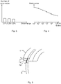
Fig. 5 schematically shows a vessel chute including a submarine power cable leaving the vessel chute. - The inventive concept will now be described more fully hereinafter with reference to the accompanying drawings, in which exemplifying embodiments are shown. The inventive concept may, however, be embodied in many different forms and should not be construed as limited to the embodiments set forth herein; rather, these embodiments are provided by way of example so that this disclosure will be thorough and complete, and will fully convey the scope of the inventive concept to those skilled in the art. Like numbers refer to like elements throughout the description.
-
Fig. 1 depicts an example of asystem 1 for fatigue-monitoring of a submarine power cable during off-shore jointing or reparation. - The
system 1 comprisesprocessing circuitry 3, astorage medium 5, and acurvature monitoring device 7. Thecurvature monitoring device 7 is configured to provide a measure of a curvature of a submarine power cable during the off-shore jointing or reparation to theprocessing circuitry 3. - The
storage medium 5 comprises computer code which when executed by theprocessing circuitry 3 causes thesystem 1 to perform the method disclosed herein. - The
processing circuitry 3 uses any combination of one or more of a suitable central processing unit (CPU), multiprocessor, microcontroller, programmable logic controller (PLC), digital signal processor (DSP), application specific integrated circuit (ASIC), field programmable gate arrays (FPGA) etc., capable of executing any herein disclosed operations concerning fatigue-monitoring of a submarine power cable during off-shore jointing or reparation. - The
storage medium 5 may for example be embodied as a memory, such as a random access memory (RAM), a read-only memory (ROM), an erasable programmable read-only memory (EPROM), or an electrically erasable programmable read-only memory (EEPROM) and more particularly as a non-volatile storage medium of a device in an external memory such as a USB (Universal Serial Bus) memory or a Flash memory, such as a compact Flash memory. - A method for fatigue-monitoring of a submarine cable during off-shore jointing or reparation performed by the
system 1 will now be described with reference toFigs 2-4 . - In the following example, the submarine power cable subjected to the off-shore jointing or repair operation comprises at least one core and a lead sheath surrounding the at least one core. The lead sheath acts as a water barrier, preventing water from penetrating into the at least one core. It should be noted that this method could also be used for medium voltage power cables without a lead sheath, in which case another metallic component, namely the conductor, the armour wire, or the screen is monitored for fatigue damage.
- When preparing for a jointing or repair operation off-shore, the vessel crew may arrange the
curvature monitoring device 7 so that the curvature of the submarine power cable may be measured. Examples of thecurvature monitoring device 7 will be provided later. - The most fatigue-sensitive region is in the region where the submarine power cable leaves the vessel chute. Heave motion of the vessel chute results in that the submarine power cable is bent and straightened against the vessel chute. Hereto, the
curvature monitoring device 7 is arranged so as to be able to monitor the curvature of the submarine power cable where it leaves the vessel chute. - The
curvature monitoring device 7 obtains curvature measurements which provide a measure of the curvature of the submarine power cable. For each iteration of the method a plurality of curvature measurements can for example be obtained over a number of minutes, such as at least 5 minutes, for example at least 10 minutes or at least 20 minutes. The measurements are hence obtained at different points in time, reflecting the dynamic movement of the submarine cable over the measurement period. - In a step a) of the method a plurality of curvature values concerning the curvature of the submarine power cable is determined. The curvature values reflect the curvature of the submarine power cable at different points in time during off-shore jointing or repair. The curvature values maybe seen as an irregular time-series of curvature values.
- The
processing circuitry 3 may be configured to determine the plurality of curvature values based on the curvature measurement made by thecurvature monitoring device 7. - The plurality of curvature ranges are determined in step a) from the plurality of curvature values. For this purpose, the rain-flow counting method may for example be used on the curvature values.
- In a step b) a plurality of strain ranges of the submarine power cable are determined based on the plurality of curvature values. In particular, the plurality of strain ranges may relate to the strain in the lead sheath of the submarine cable for different strain cycles. Alternatively, the strain ranges may relate to the strain in another metallic component of the type noted above, in case the submarine power cable is a medium voltage submarine power cable.
- In an example where step a) involves determining a plurality of curvature ranges, the plurality of strain ranges are determined based on the curvature ranges.
- Each strain range is obtained using a mathematical model of the submarine power cable. The curvature ranges are thus input values into the mathematical model, resulting in corresponding strain ranges as output.
- In another example, where no curvature ranges are determined, the curvature values are used to determine the plurality of strain values. Each strain value is obtained using a mathematical model of the submarine power cable. The curvature values are thus input values into the mathematical model, resulting in corresponding strain values as output. The strain ranges are determined based on the strain values, using for example the rain-flow counting method on the strain values.
- In case the submarine power cable is a DC submarine power cable, the curvature values or curvature ranges are sufficient as input to the mathematical model to obtain the strain values or the strain ranges. In the case the submarine power cable is an AC submarine power cable, the tension of the AC submarine power cable at each measurement instance may also be required as input together with the curvature values or curvature ranges to obtain the corresponding strain values or strain ranges.
- Additionally, in step b) the number of occurrences of each strain range stemming from the curvature measurement are determined. This can for example be obtained by using the rain flow counting method on the strain ranges. An example of a histogram showing the distribution of different strain ranges and their number of occurrence is shown in
Fig. 3 . - Next, the number of cycles to failure of the lead sheath or other metallic component for each strain range is determined. The number of cycles to failure for the strain ranges can for example be determined using an S-N fatigue curve for the lead sheath/submarine cable in the case of a high voltage power cable or for the other metallic component/submarine cable in the case of a medium voltage power cable. An example of an S-N fatigue curve is shown in
Fig. 4 . In the example, the strain ranges are on the y-axis, for example provided in percentage, and the number of cycles to failure is on the x-axis. - In a step c) a fatigue damage of the submarine power cable is determined based on the plurality of strain values.
- In step c) the fatigue damage of the submarine power cable obtained using the number of occurrences of each strain range and the number of cycles to failure for each of the strain ranges. In particular, the Palmgren-Miner linear damage hypothesis can be used to determine the fatigue damage. The
- Palmgren-miner linear damage hypothesis, also referred to as Miner's rule, states that failure occurs when

- Steps a) to c) are repeated as long as the jointing or reparation operation is ongoing, or fatigue failure is being indicated. As noted above, in every iteration, the fatigue damage becomes an accumulated fatigue damage which is determined based on the plurality of strain ranges determined in the current iteration and based on the fatigue damage of the previous iteration.
- Real-time fatigue-monitoring of the submarine power cable can thus be obtained.
- Different examples of the
curvature monitoring device 7 will now be described with reference toFig. 5 . InFig. 5 a perspective view of asubmarine power cable 9 is shown leaving avessel chute 11. In the example, thecurvature monitoring device 7 comprises a plurality ofdevices 7a configured to provide a measure of the curvature of thesubmarine power cable 9. Thedevices 7a may for example be strain gauges or inclination sensors. Alternatively, thecurvature monitoring device 7 may comprise a deflection measurement system configured to measure a deflection of the submarine power cable to thereby provide a measure of a curvature of thesubmarine cable 9. - In case the
devices 7a are strain gauges these may be positioned at 12 o'clock, i.e. at the top of thesubmarine power cable 9. Thecurvature monitoring device 7 may in this case comprise a sleeve configured to be arranged around thesubmarine power cable 9. The sleeve may for example be made of a plastic material such as polyethylene or polyurethane. InFig. 5 the sleeve is arranged around thesubmarine power cable 9 in a region where it leaves thevessel chute 11. The sleeve may extend for several metres and may contain thedevices 7a. Thedevices 7a may be provided at regular intervals from each other in the axial direction of the sleeve. Using the strain gauges, based on a time series of strain, e(t), the cable curvature κ at each location is given by
submarine power cable 9. The radius r is hence the radial distance from the centre of thesubmarine power cable 9 to the location of the strain gauge. - In case the
devices 7a are inclination sensors, the inclination sensors are configured to be mounted on thesubmarine power cable 9 at regular intervals. The average curvature between two inclination sensors is given by
submarine power cable 9. - If the
curvature monitoring system 7 comprises a deflection measurement system, the deflection of thesubmarine power cable 9 may be measured in relation to a fixed frame or reference of the vessel. The deflection can continuously be measured along the section of thesubmarine power cable 9 on thevessel chute 11. The deflection can be determined optically or using distance sensors. Hereto, the deflection measurement system may comprise a video camera and there may be provided optical markers on thesubmarine power cable 9. Alternatively, the deflection measurement system may comprise distance sensors. In either case, a polynomial curve y=f(s) can be fitted to the measured deflection as a function of the distance s along thesubmarine power cable 9. The curvature κ is given by
- The inventive concept has mainly been described above with reference to a few examples. However, as is readily appreciated by a person skilled in the art, other embodiments than the ones disclosed above are equally possible within the scope of the inventive concept, as defined by the appended claims.
Claims (6)
- Method for fatigue-monitoring of a submarine power cable (9) during off-shore jointing or reparation, the method comprising:a) determining a plurality of curvature values concerning a curvature of the submarine power cable (9) at different points in time during the off-shore jointing or reparation,b) determining a plurality of strain ranges of the submarine power cable (9) based on the plurality of curvature values,
wherein in step b) the determining of each strain range involves using a mathematical model of the submarine power cable (9), andc) determining a fatigue damage of the submarine power cable (9) based on the plurality of strain ranges,wherein step b) comprises determining a number of occurrences of each strain range, wherein in step c) the fatigue damage is determined based on the number of occurrences of each strain range, andwherein in step a) the determining involves obtaining measurements of a curvature of the submarine power cable (9) from a curvature monitoring device monitoring the submarine power cable (9) where the submarine power cable leaves the vessel chute (11). - The method as claimed in claim 1, comprising repeating steps a) to c) during the off-shore jointing or reparation, wherein in each iteration of step c) the fatigue damage is determined based on the plurality of strain ranges determined in step b) of the current iteration and on the fatigue damage determined in the previous iteration of step c) thereby obtaining an accumulated fatigue damage.
- The method as claimed in claim 1 or 2, further comprising determining a number of cycles to failure of a lead sheath or other metallic component of the submarine power cable (9) for each strain range, wherein in step c) the fatigue damage is determined further based on the number of cycles to failure for each strain range.
- The method as claimed in claim 3, wherein the number of cycles to failure for each strain range is determined using an S-N fatigue curve for the lead sheath or the other metallic component of the submarine power cable (9).
- The method as claimed in claim 3 or 4, wherein step c) involves using the number of occurrences of each strain range and the corresponding number of cycles to failure with the Palmgren-Miner linear damage hypothesis to determine the fatigue damage.
- System (1) for fatigue-monitoring of a submarine power cable (9) during off-shore jointing or reparation, the system (1) comprising:a curvature monitoring device (7) configured to provide a measure of a curvature of the submarine power cable (9),a storage medium (5) comprising computer code, andprocessing circuitry (3) which when executing the computer code causes the system (1) to perform the method as claimed in any of claims 1-5,wherein the curvature monitoring device (7) comprises a sleeve placed around the submarine power cable where it leaves a vessel chute (11), which sleeve includes a plurality of strain gauges (7a) positioned at regular intervals from each other in the axial direction of the sleeve, and which strain gauges (7a) are configured to provide a measure of a curvature of the submarine power cable (9), orwherein the curvature monitoring device (7) comprises inclination sensors (7a) mounted on the submarine power cable (9) where it leaves a vessel chute (11), which inclination sensors (7a) are configured to provide a measure of a curvature of the submarine power cable (9), orwherein the curvature monitoring device (7) comprises a cable deflection measurement system configured to continuously measure a deflection of the submarine power cable (9) along a section of the submarine power cable (9) on a vessel chute (11) to provide a measure of a curvature of the submarine power cable (9).
Priority Applications (10)
| Application Number | Priority Date | Filing Date | Title |
|---|---|---|---|
| EP17200664.5A EP3483579B1 (en) | 2017-11-08 | 2017-11-08 | Method and system for fatigue-monitoring of a submarine cable in off-shore operations |
| DK17200664.5T DK3483579T3 (en) | 2017-11-08 | 2017-11-08 | METHOD AND SYSTEM FOR FATIGUE MONITORING OF A SUBSEA CABLE IN OFFSHORE OPERATIONS |
| ES17200664T ES2929186T3 (en) | 2017-11-08 | 2017-11-08 | Method and system for monitoring the deterioration of a submarine cable in operations at sea |
| PT172006645T PT3483579T (en) | 2017-11-08 | 2017-11-08 | Method and system for fatigue-monitoring of a submarine cable in off-shore operations |
| PL17200664.5T PL3483579T3 (en) | 2017-11-08 | 2017-11-08 | Method and system for fatigue-monitoring of a submarine cable in off-shore operations |
| JP2020523019A JP7254789B2 (en) | 2017-11-08 | 2018-11-07 | Method and system for monitoring subsea cable fatigue in offshore operations |
| PCT/EP2018/080522 WO2019092053A1 (en) | 2017-11-08 | 2018-11-07 | Method and system for fatigue-monitoring of a submarine cable in off-shore operations |
| KR1020207014423A KR20200081409A (en) | 2017-11-08 | 2018-11-07 | Method and system for fatigue monitoring of submarine cables in offshore operation |
| CA3081783A CA3081783A1 (en) | 2017-11-08 | 2018-11-07 | Method and system for fatigue-monitoring of a submarine cable in off-shore operations |
| US16/758,574 US11346744B2 (en) | 2017-11-08 | 2018-11-07 | Method and system for fatigue-monitoring of a submarine cable in off-shore operations |
Applications Claiming Priority (1)
| Application Number | Priority Date | Filing Date | Title |
|---|---|---|---|
| EP17200664.5A EP3483579B1 (en) | 2017-11-08 | 2017-11-08 | Method and system for fatigue-monitoring of a submarine cable in off-shore operations |
Publications (2)
| Publication Number | Publication Date |
|---|---|
| EP3483579A1 EP3483579A1 (en) | 2019-05-15 |
| EP3483579B1 true EP3483579B1 (en) | 2022-07-27 |
Family
ID=60484112
Family Applications (1)
| Application Number | Title | Priority Date | Filing Date |
|---|---|---|---|
| EP17200664.5A Active EP3483579B1 (en) | 2017-11-08 | 2017-11-08 | Method and system for fatigue-monitoring of a submarine cable in off-shore operations |
Country Status (10)
| Country | Link |
|---|---|
| US (1) | US11346744B2 (en) |
| EP (1) | EP3483579B1 (en) |
| JP (1) | JP7254789B2 (en) |
| KR (1) | KR20200081409A (en) |
| CA (1) | CA3081783A1 (en) |
| DK (1) | DK3483579T3 (en) |
| ES (1) | ES2929186T3 (en) |
| PL (1) | PL3483579T3 (en) |
| PT (1) | PT3483579T (en) |
| WO (1) | WO2019092053A1 (en) |
Families Citing this family (2)
| Publication number | Priority date | Publication date | Assignee | Title |
|---|---|---|---|---|
| EP3992601A1 (en) | 2020-10-29 | 2022-05-04 | NKT HV Cables AB | Submarine power cable with curvature monitoring capability |
| CN114279676A (en) * | 2021-11-23 | 2022-04-05 | 国核电力规划设计研究院有限公司 | Sea condition threshold judgment method for strain damage of submarine suspended cable |
Family Cites Families (41)
| Publication number | Priority date | Publication date | Assignee | Title |
|---|---|---|---|---|
| IT1153466B (en) * | 1982-02-22 | 1987-01-14 | Pirelli Cavi Spa | PROCEDURE FOR LAYING A SUBMARINE CABLE |
| JPS6338137A (en) * | 1986-08-04 | 1988-02-18 | Nippon Telegr & Teleph Corp <Ntt> | Diagnosis device for deterioration of lead-clad cable |
| GB8729061D0 (en) * | 1987-12-12 | 1988-01-27 | British Petroleum Co Plc | Gauge |
| SE9500512L (en) * | 1995-02-13 | 1996-07-22 | Reflex Instr Ab | Apparatus for determining the curvature of an elongated channel such as a borehole in rock |
| JP4277969B2 (en) | 1999-06-22 | 2009-06-10 | 株式会社フジクラ | Fatigue method and equipment for underwater cable |
| WO2002041195A2 (en) * | 2000-11-17 | 2002-05-23 | Battelle Memorial Institute | Structural stress analysis |
| US7194913B2 (en) * | 2002-08-26 | 2007-03-27 | Shell Oil Company | Apparatuses and methods for monitoring stress in steel catenary risers |
| US6854327B2 (en) * | 2002-11-06 | 2005-02-15 | Shell Oil Company | Apparatus and method for monitoring compaction |
| US7277162B2 (en) * | 2003-01-23 | 2007-10-02 | Jerry Gene Williams | Dynamic performance monitoring of long slender structures using optical fiber strain sensors |
| US7599249B2 (en) * | 2003-07-21 | 2009-10-06 | Westerngeco L.L.C. | Cable motion detection |
| US7781725B2 (en) * | 2004-10-21 | 2010-08-24 | Mossman Guy E | Optical fiber based sensor system suitable for monitoring remote aqueous infiltration |
| ATE433044T1 (en) * | 2004-08-27 | 2009-06-15 | Schlumberger Holdings | SENSOR AND MEASURING DEVICE FOR DETERMINING THE BENDING RADIUS AND SHAPE OF A PIPE |
| BRPI0608498A2 (en) * | 2005-03-23 | 2010-11-16 | Shell Intyernationale Res Mij | system and method for remotely detecting properties of an undersea structure |
| WO2008021881A2 (en) * | 2006-08-09 | 2008-02-21 | Shell Oil Company | Method of applying a string of interconnected strain sensors to an object, a pliable support structure, and method of producing a mineral hydrocarbon fluid |
| GB0620944D0 (en) * | 2006-10-20 | 2006-11-29 | Insensys Ltd | Curvature measurement moving relative to pipe |
| EP2050103A1 (en) | 2006-12-12 | 2009-04-22 | ABB Technology Ltd | Monitoring a flexible power cable |
| US7889840B2 (en) * | 2007-01-10 | 2011-02-15 | The United States Of America As Represented By The Secretary Of The Navy | System and method for predicting material fatigue and damage |
| DK2436015T3 (en) * | 2009-05-27 | 2017-11-06 | Prysmian Spa | Electric cable with load sensor and monitoring system and method for detecting load in at least one electric cable |
| US20110054840A1 (en) * | 2009-08-26 | 2011-03-03 | Hively Lee M | Failure prediction of complex structures under arbitrary time-serial loading condition |
| CA2773747C (en) * | 2009-09-18 | 2017-01-03 | Prysmian S.P.A. | Electric cable with bending sensor and monitoring system and method for detecting bending in at least one electric cable |
| GB201018534D0 (en) * | 2010-11-03 | 2010-12-15 | Wellstream Int Ltd | Parameter sensing and monitoring |
| WO2012061979A1 (en) * | 2010-11-09 | 2012-05-18 | Abb Research Ltd. | Cable fatigue monitor and method thereof |
| EP2638236B1 (en) | 2010-11-09 | 2018-10-10 | GE Oil & Gas UK Limited | Riser assembly and method |
| US20120271566A1 (en) * | 2011-04-21 | 2012-10-25 | Vinayak Deshmukh | Method for the prediction of fatigue life for structures |
| EP2530449B1 (en) * | 2011-06-03 | 2014-04-23 | Soletanche Freyssinet | Method for determining the fatigue capital of a cable |
| GB201122364D0 (en) * | 2011-12-28 | 2012-02-01 | Wellstream Int Ltd | Flexible pipe body and method |
| CN104220858B (en) * | 2012-03-05 | 2016-05-25 | 普睿司曼股份公司 | For detection of the method for the distortion in cable, there is the cable of twist sensors and the method for the manufacture of described cable |
| JP5962443B2 (en) | 2012-11-06 | 2016-08-03 | 日立金属株式会社 | Method and apparatus for predicting cable breakage life |
| NO3074325T3 (en) | 2013-12-23 | 2018-02-24 | ||
| GB2522709B (en) * | 2014-02-04 | 2017-07-19 | Aquaterra Energy Ltd | An offshore pipe monitoring system |
| GB201411874D0 (en) * | 2014-07-03 | 2014-08-20 | Wellstream Int Ltd | Curvature sensor and sensing method |
| EP3230199B1 (en) * | 2014-12-10 | 2020-06-24 | Paul D. Okulov | Micro electro-mechanical strain displacement sensor and usage monitoring system |
| WO2016102968A1 (en) * | 2014-12-23 | 2016-06-30 | Ore Catapult Development Services Limited | Fatigue testing |
| PL3347903T3 (en) * | 2015-09-10 | 2021-05-31 | Prysmian S.P.A. | Cable with optical-fiber sensor for measuring strain |
| WO2017147679A1 (en) * | 2016-03-01 | 2017-09-08 | Hifi Engineering Inc. | Method and system for determining whether an event has occurred from dynamic strain measurements |
| US10883894B2 (en) * | 2016-09-16 | 2021-01-05 | Onesubsea Ip Uk Limited | Conduit fatigue management systems and methods |
| CA3043854A1 (en) * | 2016-12-21 | 2018-06-28 | Halliburton Energy Services, Inc. | Downhole sensing cable system for improved seismic energy coupling to the cable system |
| US20210115780A1 (en) * | 2017-03-14 | 2021-04-22 | Wfs Technologies Limited | Subsea structure monitoring system |
| US20200080416A1 (en) * | 2017-05-26 | 2020-03-12 | Halliburton Energy Services, Inc. | Fatigue Monitoring Of Coiled Tubing In Downline Deployments |
| WO2018222555A1 (en) * | 2017-05-30 | 2018-12-06 | The Texas A&M University System | Apparatus and method for predicting a deformed shape of a structure |
| DE102018110500A1 (en) * | 2017-09-04 | 2019-03-07 | Schott Ag | Bendable and / or foldable articles and methods of providing bendable and / or foldable articles |
-
2017
- 2017-11-08 DK DK17200664.5T patent/DK3483579T3/en active
- 2017-11-08 EP EP17200664.5A patent/EP3483579B1/en active Active
- 2017-11-08 PL PL17200664.5T patent/PL3483579T3/en unknown
- 2017-11-08 ES ES17200664T patent/ES2929186T3/en active Active
- 2017-11-08 PT PT172006645T patent/PT3483579T/en unknown
-
2018
- 2018-11-07 JP JP2020523019A patent/JP7254789B2/en active Active
- 2018-11-07 US US16/758,574 patent/US11346744B2/en active Active
- 2018-11-07 WO PCT/EP2018/080522 patent/WO2019092053A1/en active Application Filing
- 2018-11-07 CA CA3081783A patent/CA3081783A1/en active Pending
- 2018-11-07 KR KR1020207014423A patent/KR20200081409A/en not_active Application Discontinuation
Also Published As
| Publication number | Publication date |
|---|---|
| EP3483579A1 (en) | 2019-05-15 |
| KR20200081409A (en) | 2020-07-07 |
| ES2929186T3 (en) | 2022-11-25 |
| JP2021502547A (en) | 2021-01-28 |
| CA3081783A1 (en) | 2019-05-16 |
| JP7254789B2 (en) | 2023-04-10 |
| PL3483579T3 (en) | 2022-12-19 |
| DK3483579T3 (en) | 2022-10-17 |
| WO2019092053A1 (en) | 2019-05-16 |
| PT3483579T (en) | 2022-10-07 |
| US20200348204A1 (en) | 2020-11-05 |
| US11346744B2 (en) | 2022-05-31 |
Similar Documents
| Publication | Publication Date | Title |
|---|---|---|
| US11346744B2 (en) | Method and system for fatigue-monitoring of a submarine cable in off-shore operations | |
| EP2436015B1 (en) | Electric cable with strain sensor and monitoring system and method for detecting strain in at least one electric cable | |
| EP3245493B1 (en) | Structural damage detection | |
| JP6783328B2 (en) | Equipment, supply line body for the device, sensor line body and twist measurement method | |
| CN105092133B (en) | Apparatus and method for electromechanical cable overstress indication | |
| EP3356991B1 (en) | Non-destructive evaluation of cordage products | |
| US11862362B2 (en) | Submarine power cable with curvature monitoring capability | |
| RU2729304C1 (en) | Control method of stress-strain state of buried pipeline | |
| Reda et al. | Compression limit state of HVAC submarine cables | |
| EP2902584A2 (en) | An offshore pipe monitoring system | |
| EP3161440B1 (en) | A method of determining deformation in a structure | |
| JP2010279202A (en) | System for control of utility pole stress | |
| JP2021502547A5 (en) | ||
| JP4696083B2 (en) | Vibration life estimation method and vibration life estimation program for overhead wire | |
| Hedlund | Modelling of viscoelastic dynamic bending stiffness for VIV analysis of submarine cables | |
| Connaire et al. | Methodology for Mitigation of Armour Wire Bird Caging in Offshore Wind Export Cables | |
| Svoma et al. | Integrated condition monitoring for subsea power cable systems | |
| CN114877807B (en) | High-voltage cable line displacement monitoring system and method for pumped storage power station | |
| RU2550826C2 (en) | Method to measure stresses in structure without removal of static loads | |
| Fjeldstad et al. | Structural Analysis and Load Monitoring of a Loss of Tension Incident | |
| Baker et al. | Fatigue Considerations for Subsea Well Systems | |
| JP4396424B2 (en) | Trolley wire wear detection method | |
| CN116757043A (en) | Mining pipeline defect analysis method, system, terminal equipment and storage medium | |
| CN116627098A (en) | Control cable production system and production method for high-speed drag chain system | |
| CN116087676A (en) | Method and system for evaluating internal mechanical state and load capacity of bridge-following cable |
Legal Events
| Date | Code | Title | Description |
|---|---|---|---|
| PUAI | Public reference made under article 153(3) epc to a published international application that has entered the european phase |
Free format text: ORIGINAL CODE: 0009012 |
|
| STAA | Information on the status of an ep patent application or granted ep patent |
Free format text: STATUS: THE APPLICATION HAS BEEN PUBLISHED |
|
| AK | Designated contracting states |
Kind code of ref document: A1 Designated state(s): AL AT BE BG CH CY CZ DE DK EE ES FI FR GB GR HR HU IE IS IT LI LT LU LV MC MK MT NL NO PL PT RO RS SE SI SK SM TR |
|
| AX | Request for extension of the european patent |
Extension state: BA ME |
|
| STAA | Information on the status of an ep patent application or granted ep patent |
Free format text: STATUS: REQUEST FOR EXAMINATION WAS MADE |
|
| 17P | Request for examination filed |
Effective date: 20191114 |
|
| RBV | Designated contracting states (corrected) |
Designated state(s): AL AT BE BG CH CY CZ DE DK EE ES FI FR GB GR HR HU IE IS IT LI LT LU LV MC MK MT NL NO PL PT RO RS SE SI SK SM TR |
|
| STAA | Information on the status of an ep patent application or granted ep patent |
Free format text: STATUS: EXAMINATION IS IN PROGRESS |
|
| 17Q | First examination report despatched |
Effective date: 20200316 |
|
| STAA | Information on the status of an ep patent application or granted ep patent |
Free format text: STATUS: EXAMINATION IS IN PROGRESS |
|
| GRAP | Despatch of communication of intention to grant a patent |
Free format text: ORIGINAL CODE: EPIDOSNIGR1 |
|
| STAA | Information on the status of an ep patent application or granted ep patent |
Free format text: STATUS: GRANT OF PATENT IS INTENDED |
|
| INTG | Intention to grant announced |
Effective date: 20210920 |
|
| GRAJ | Information related to disapproval of communication of intention to grant by the applicant or resumption of examination proceedings by the epo deleted |
Free format text: ORIGINAL CODE: EPIDOSDIGR1 |
|
| STAA | Information on the status of an ep patent application or granted ep patent |
Free format text: STATUS: EXAMINATION IS IN PROGRESS |
|
| GRAP | Despatch of communication of intention to grant a patent |
Free format text: ORIGINAL CODE: EPIDOSNIGR1 |
|
| STAA | Information on the status of an ep patent application or granted ep patent |
Free format text: STATUS: GRANT OF PATENT IS INTENDED |
|
| INTC | Intention to grant announced (deleted) | ||
| INTG | Intention to grant announced |
Effective date: 20220214 |
|
| GRAS | Grant fee paid |
Free format text: ORIGINAL CODE: EPIDOSNIGR3 |
|
| GRAA | (expected) grant |
Free format text: ORIGINAL CODE: 0009210 |
|
| STAA | Information on the status of an ep patent application or granted ep patent |
Free format text: STATUS: THE PATENT HAS BEEN GRANTED |
|
| AK | Designated contracting states |
Kind code of ref document: B1 Designated state(s): AL AT BE BG CH CY CZ DE DK EE ES FI FR GB GR HR HU IE IS IT LI LT LU LV MC MK MT NL NO PL PT RO RS SE SI SK SM TR |
|
| REG | Reference to a national code |
Ref country code: CH Ref legal event code: EP |
|
| REG | Reference to a national code |
Ref country code: AT Ref legal event code: REF Ref document number: 1507363 Country of ref document: AT Kind code of ref document: T Effective date: 20220815 |
|
| REG | Reference to a national code |
Ref country code: DE Ref legal event code: R096 Ref document number: 602017059831 Country of ref document: DE |
|
| REG | Reference to a national code |
Ref country code: IE Ref legal event code: FG4D |
|
| REG | Reference to a national code |
Ref country code: PT Ref legal event code: SC4A Ref document number: 3483579 Country of ref document: PT Date of ref document: 20221007 Kind code of ref document: T Free format text: AVAILABILITY OF NATIONAL TRANSLATION Effective date: 20221003 |
|
| REG | Reference to a national code |
Ref country code: DK Ref legal event code: T3 Effective date: 20221011 |
|
| REG | Reference to a national code |
Ref country code: NO Ref legal event code: T2 Effective date: 20220727 |
|
| REG | Reference to a national code |
Ref country code: NL Ref legal event code: FP |
|
| REG | Reference to a national code |
Ref country code: LT Ref legal event code: MG9D |
|
| REG | Reference to a national code |
Ref country code: SE Ref legal event code: TRGR |
|
| REG | Reference to a national code |
Ref country code: ES Ref legal event code: FG2A Ref document number: 2929186 Country of ref document: ES Kind code of ref document: T3 Effective date: 20221125 |
|
| REG | Reference to a national code |
Ref country code: GR Ref legal event code: EP Ref document number: 20220402106 Country of ref document: GR Effective date: 20221212 |
|
| PG25 | Lapsed in a contracting state [announced via postgrant information from national office to epo] |
Ref country code: RS Free format text: LAPSE BECAUSE OF FAILURE TO SUBMIT A TRANSLATION OF THE DESCRIPTION OR TO PAY THE FEE WITHIN THE PRESCRIBED TIME-LIMIT Effective date: 20220727 Ref country code: LV Free format text: LAPSE BECAUSE OF FAILURE TO SUBMIT A TRANSLATION OF THE DESCRIPTION OR TO PAY THE FEE WITHIN THE PRESCRIBED TIME-LIMIT Effective date: 20220727 Ref country code: LT Free format text: LAPSE BECAUSE OF FAILURE TO SUBMIT A TRANSLATION OF THE DESCRIPTION OR TO PAY THE FEE WITHIN THE PRESCRIBED TIME-LIMIT Effective date: 20220727 |
|
| REG | Reference to a national code |
Ref country code: AT Ref legal event code: MK05 Ref document number: 1507363 Country of ref document: AT Kind code of ref document: T Effective date: 20220727 |
|
| PG25 | Lapsed in a contracting state [announced via postgrant information from national office to epo] |
Ref country code: IS Free format text: LAPSE BECAUSE OF FAILURE TO SUBMIT A TRANSLATION OF THE DESCRIPTION OR TO PAY THE FEE WITHIN THE PRESCRIBED TIME-LIMIT Effective date: 20221127 Ref country code: HR Free format text: LAPSE BECAUSE OF FAILURE TO SUBMIT A TRANSLATION OF THE DESCRIPTION OR TO PAY THE FEE WITHIN THE PRESCRIBED TIME-LIMIT Effective date: 20220727 |
|
| PG25 | Lapsed in a contracting state [announced via postgrant information from national office to epo] |
Ref country code: SM Free format text: LAPSE BECAUSE OF FAILURE TO SUBMIT A TRANSLATION OF THE DESCRIPTION OR TO PAY THE FEE WITHIN THE PRESCRIBED TIME-LIMIT Effective date: 20220727 Ref country code: RO Free format text: LAPSE BECAUSE OF FAILURE TO SUBMIT A TRANSLATION OF THE DESCRIPTION OR TO PAY THE FEE WITHIN THE PRESCRIBED TIME-LIMIT Effective date: 20220727 Ref country code: CZ Free format text: LAPSE BECAUSE OF FAILURE TO SUBMIT A TRANSLATION OF THE DESCRIPTION OR TO PAY THE FEE WITHIN THE PRESCRIBED TIME-LIMIT Effective date: 20220727 Ref country code: AT Free format text: LAPSE BECAUSE OF FAILURE TO SUBMIT A TRANSLATION OF THE DESCRIPTION OR TO PAY THE FEE WITHIN THE PRESCRIBED TIME-LIMIT Effective date: 20220727 |
|
| REG | Reference to a national code |
Ref country code: DE Ref legal event code: R097 Ref document number: 602017059831 Country of ref document: DE |
|
| PG25 | Lapsed in a contracting state [announced via postgrant information from national office to epo] |
Ref country code: SK Free format text: LAPSE BECAUSE OF FAILURE TO SUBMIT A TRANSLATION OF THE DESCRIPTION OR TO PAY THE FEE WITHIN THE PRESCRIBED TIME-LIMIT Effective date: 20220727 Ref country code: EE Free format text: LAPSE BECAUSE OF FAILURE TO SUBMIT A TRANSLATION OF THE DESCRIPTION OR TO PAY THE FEE WITHIN THE PRESCRIBED TIME-LIMIT Effective date: 20220727 |
|
| REG | Reference to a national code |
Ref country code: DE Ref legal event code: R119 Ref document number: 602017059831 Country of ref document: DE |
|
| PLBE | No opposition filed within time limit |
Free format text: ORIGINAL CODE: 0009261 |
|
| STAA | Information on the status of an ep patent application or granted ep patent |
Free format text: STATUS: NO OPPOSITION FILED WITHIN TIME LIMIT |
|
| PG25 | Lapsed in a contracting state [announced via postgrant information from national office to epo] |
Ref country code: MC Free format text: LAPSE BECAUSE OF FAILURE TO SUBMIT A TRANSLATION OF THE DESCRIPTION OR TO PAY THE FEE WITHIN THE PRESCRIBED TIME-LIMIT Effective date: 20220727 Ref country code: AL Free format text: LAPSE BECAUSE OF FAILURE TO SUBMIT A TRANSLATION OF THE DESCRIPTION OR TO PAY THE FEE WITHIN THE PRESCRIBED TIME-LIMIT Effective date: 20220727 |
|
| REG | Reference to a national code |
Ref country code: CH Ref legal event code: PL |
|
| 26N | No opposition filed |
Effective date: 20230502 |
|
| P01 | Opt-out of the competence of the unified patent court (upc) registered |
Effective date: 20230527 |
|
| PG25 | Lapsed in a contracting state [announced via postgrant information from national office to epo] |
Ref country code: LI Free format text: LAPSE BECAUSE OF NON-PAYMENT OF DUE FEES Effective date: 20221130 Ref country code: CH Free format text: LAPSE BECAUSE OF NON-PAYMENT OF DUE FEES Effective date: 20221130 |
|
| PG25 | Lapsed in a contracting state [announced via postgrant information from national office to epo] |
Ref country code: SI Free format text: LAPSE BECAUSE OF FAILURE TO SUBMIT A TRANSLATION OF THE DESCRIPTION OR TO PAY THE FEE WITHIN THE PRESCRIBED TIME-LIMIT Effective date: 20220727 Ref country code: LU Free format text: LAPSE BECAUSE OF NON-PAYMENT OF DUE FEES Effective date: 20221108 |
|
| PG25 | Lapsed in a contracting state [announced via postgrant information from national office to epo] |
Ref country code: DE Free format text: LAPSE BECAUSE OF NON-PAYMENT OF DUE FEES Effective date: 20230601 |
|
| PGFP | Annual fee paid to national office [announced via postgrant information from national office to epo] |
Ref country code: NL Payment date: 20231120 Year of fee payment: 7 |
|
| PGFP | Annual fee paid to national office [announced via postgrant information from national office to epo] |
Ref country code: GB Payment date: 20231120 Year of fee payment: 7 Ref country code: GR Payment date: 20231120 Year of fee payment: 7 |
|
| PGFP | Annual fee paid to national office [announced via postgrant information from national office to epo] |
Ref country code: ES Payment date: 20231213 Year of fee payment: 7 |
|
| PGFP | Annual fee paid to national office [announced via postgrant information from national office to epo] |
Ref country code: SE Payment date: 20231121 Year of fee payment: 7 Ref country code: PT Payment date: 20231009 Year of fee payment: 7 Ref country code: NO Payment date: 20231121 Year of fee payment: 7 Ref country code: IT Payment date: 20231120 Year of fee payment: 7 Ref country code: IE Payment date: 20231121 Year of fee payment: 7 Ref country code: FR Payment date: 20231115 Year of fee payment: 7 Ref country code: FI Payment date: 20231120 Year of fee payment: 7 Ref country code: DK Payment date: 20231117 Year of fee payment: 7 |
|
| PGFP | Annual fee paid to national office [announced via postgrant information from national office to epo] |
Ref country code: PL Payment date: 20231030 Year of fee payment: 7 Ref country code: BE Payment date: 20231120 Year of fee payment: 7 |
|
| PG25 | Lapsed in a contracting state [announced via postgrant information from national office to epo] |
Ref country code: HU Free format text: LAPSE BECAUSE OF FAILURE TO SUBMIT A TRANSLATION OF THE DESCRIPTION OR TO PAY THE FEE WITHIN THE PRESCRIBED TIME-LIMIT; INVALID AB INITIO Effective date: 20171108 |
|
| PG25 | Lapsed in a contracting state [announced via postgrant information from national office to epo] |
Ref country code: CY Free format text: LAPSE BECAUSE OF FAILURE TO SUBMIT A TRANSLATION OF THE DESCRIPTION OR TO PAY THE FEE WITHIN THE PRESCRIBED TIME-LIMIT Effective date: 20220727 |