EP3481476B1 - Smart oscillating positive expiratory pressure device - Google Patents
Smart oscillating positive expiratory pressure device Download PDFInfo
- Publication number
- EP3481476B1 EP3481476B1 EP17823750.9A EP17823750A EP3481476B1 EP 3481476 B1 EP3481476 B1 EP 3481476B1 EP 17823750 A EP17823750 A EP 17823750A EP 3481476 B1 EP3481476 B1 EP 3481476B1
- Authority
- EP
- European Patent Office
- Prior art keywords
- pressure
- opep
- output
- user
- sensor
- Prior art date
- Legal status (The legal status is an assumption and is not a legal conclusion. Google has not performed a legal analysis and makes no representation as to the accuracy of the status listed.)
- Active
Links
- 239000012528 membrane Substances 0.000 claims description 24
- 238000004891 communication Methods 0.000 claims description 23
- 230000002596 correlated effect Effects 0.000 claims description 13
- 230000000007 visual effect Effects 0.000 claims description 6
- 230000004044 response Effects 0.000 claims description 5
- 238000000034 method Methods 0.000 description 26
- 230000036961 partial effect Effects 0.000 description 17
- 238000011282 treatment Methods 0.000 description 16
- 230000003434 inspiratory effect Effects 0.000 description 15
- 238000012545 processing Methods 0.000 description 13
- 238000005259 measurement Methods 0.000 description 11
- 230000010355 oscillation Effects 0.000 description 11
- 230000008859 change Effects 0.000 description 10
- 238000002560 therapeutic procedure Methods 0.000 description 10
- 230000007246 mechanism Effects 0.000 description 9
- 238000006073 displacement reaction Methods 0.000 description 8
- 230000006870 function Effects 0.000 description 8
- 238000004458 analytical method Methods 0.000 description 7
- 230000007423 decrease Effects 0.000 description 6
- 239000012530 fluid Substances 0.000 description 6
- 208000006545 Chronic Obstructive Pulmonary Disease Diseases 0.000 description 5
- 206010011224 Cough Diseases 0.000 description 5
- 229920001296 polysiloxane Polymers 0.000 description 5
- 201000003883 Cystic fibrosis Diseases 0.000 description 4
- 230000005355 Hall effect Effects 0.000 description 4
- 230000001276 controlling effect Effects 0.000 description 4
- 230000036541 health Effects 0.000 description 4
- 238000012417 linear regression Methods 0.000 description 4
- 210000004072 lung Anatomy 0.000 description 4
- 230000008569 process Effects 0.000 description 4
- 230000029058 respiratory gaseous exchange Effects 0.000 description 4
- 239000000443 aerosol Substances 0.000 description 3
- 238000004140 cleaning Methods 0.000 description 3
- 238000010586 diagram Methods 0.000 description 3
- 201000010099 disease Diseases 0.000 description 3
- 208000037265 diseases, disorders, signs and symptoms Diseases 0.000 description 3
- 230000000241 respiratory effect Effects 0.000 description 3
- 230000001953 sensory effect Effects 0.000 description 3
- 238000012549 training Methods 0.000 description 3
- 230000008901 benefit Effects 0.000 description 2
- 230000001413 cellular effect Effects 0.000 description 2
- 230000006835 compression Effects 0.000 description 2
- 238000007906 compression Methods 0.000 description 2
- 230000003247 decreasing effect Effects 0.000 description 2
- 230000009977 dual effect Effects 0.000 description 2
- 230000033001 locomotion Effects 0.000 description 2
- 230000000276 sedentary effect Effects 0.000 description 2
- 230000005236 sound signal Effects 0.000 description 2
- 238000012546 transfer Methods 0.000 description 2
- 206010013082 Discomfort Diseases 0.000 description 1
- 208000000059 Dyspnea Diseases 0.000 description 1
- 206010013975 Dyspnoeas Diseases 0.000 description 1
- 241001465754 Metazoa Species 0.000 description 1
- 206010049565 Muscle fatigue Diseases 0.000 description 1
- 230000001133 acceleration Effects 0.000 description 1
- 230000009286 beneficial effect Effects 0.000 description 1
- 230000005540 biological transmission Effects 0.000 description 1
- 238000004364 calculation method Methods 0.000 description 1
- 238000006243 chemical reaction Methods 0.000 description 1
- 239000003795 chemical substances by application Substances 0.000 description 1
- 230000003749 cleanliness Effects 0.000 description 1
- 238000011109 contamination Methods 0.000 description 1
- 230000000875 corresponding effect Effects 0.000 description 1
- 238000013500 data storage Methods 0.000 description 1
- 230000001419 dependent effect Effects 0.000 description 1
- 230000000249 desinfective effect Effects 0.000 description 1
- 238000001514 detection method Methods 0.000 description 1
- 238000005516 engineering process Methods 0.000 description 1
- 238000001914 filtration Methods 0.000 description 1
- 238000009499 grossing Methods 0.000 description 1
- 230000000670 limiting effect Effects 0.000 description 1
- 239000004973 liquid crystal related substance Substances 0.000 description 1
- 238000012544 monitoring process Methods 0.000 description 1
- 210000003097 mucus Anatomy 0.000 description 1
- 230000003287 optical effect Effects 0.000 description 1
- 230000008520 organization Effects 0.000 description 1
- 229920001690 polydopamine Polymers 0.000 description 1
- 230000002980 postoperative effect Effects 0.000 description 1
- 230000002685 pulmonary effect Effects 0.000 description 1
- 230000002829 reductive effect Effects 0.000 description 1
- 238000011160 research Methods 0.000 description 1
- 210000003019 respiratory muscle Anatomy 0.000 description 1
- 238000012552 review Methods 0.000 description 1
- 238000005096 rolling process Methods 0.000 description 1
- 230000003068 static effect Effects 0.000 description 1
- 239000000758 substrate Substances 0.000 description 1
- 230000002123 temporal effect Effects 0.000 description 1
Images


Classifications
-
- A—HUMAN NECESSITIES
- A61—MEDICAL OR VETERINARY SCIENCE; HYGIENE
- A61M—DEVICES FOR INTRODUCING MEDIA INTO, OR ONTO, THE BODY; DEVICES FOR TRANSDUCING BODY MEDIA OR FOR TAKING MEDIA FROM THE BODY; DEVICES FOR PRODUCING OR ENDING SLEEP OR STUPOR
- A61M16/00—Devices for influencing the respiratory system of patients by gas treatment, e.g. mouth-to-mouth respiration; Tracheal tubes
- A61M16/0003—Accessories therefor, e.g. sensors, vibrators, negative pressure
- A61M16/0006—Accessories therefor, e.g. sensors, vibrators, negative pressure with means for creating vibrations in patients' airways
-
- A—HUMAN NECESSITIES
- A61—MEDICAL OR VETERINARY SCIENCE; HYGIENE
- A61B—DIAGNOSIS; SURGERY; IDENTIFICATION
- A61B5/00—Measuring for diagnostic purposes; Identification of persons
- A61B5/08—Detecting, measuring or recording devices for evaluating the respiratory organs
- A61B5/087—Measuring breath flow
- A61B5/0876—Measuring breath flow using means deflected by the fluid stream, e.g. flaps
-
- A—HUMAN NECESSITIES
- A61—MEDICAL OR VETERINARY SCIENCE; HYGIENE
- A61B—DIAGNOSIS; SURGERY; IDENTIFICATION
- A61B2562/00—Details of sensors; Constructional details of sensor housings or probes; Accessories for sensors
- A61B2562/02—Details of sensors specially adapted for in-vivo measurements
- A61B2562/0219—Inertial sensors, e.g. accelerometers, gyroscopes, tilt switches
-
- A—HUMAN NECESSITIES
- A61—MEDICAL OR VETERINARY SCIENCE; HYGIENE
- A61M—DEVICES FOR INTRODUCING MEDIA INTO, OR ONTO, THE BODY; DEVICES FOR TRANSDUCING BODY MEDIA OR FOR TAKING MEDIA FROM THE BODY; DEVICES FOR PRODUCING OR ENDING SLEEP OR STUPOR
- A61M16/00—Devices for influencing the respiratory system of patients by gas treatment, e.g. mouth-to-mouth respiration; Tracheal tubes
- A61M16/0003—Accessories therefor, e.g. sensors, vibrators, negative pressure
- A61M16/0009—Accessories therefor, e.g. sensors, vibrators, negative pressure with sub-atmospheric pressure, e.g. during expiration
-
- A—HUMAN NECESSITIES
- A61—MEDICAL OR VETERINARY SCIENCE; HYGIENE
- A61M—DEVICES FOR INTRODUCING MEDIA INTO, OR ONTO, THE BODY; DEVICES FOR TRANSDUCING BODY MEDIA OR FOR TAKING MEDIA FROM THE BODY; DEVICES FOR PRODUCING OR ENDING SLEEP OR STUPOR
- A61M16/00—Devices for influencing the respiratory system of patients by gas treatment, e.g. mouth-to-mouth respiration; Tracheal tubes
- A61M16/021—Devices for influencing the respiratory system of patients by gas treatment, e.g. mouth-to-mouth respiration; Tracheal tubes operated by electrical means
- A61M16/022—Control means therefor
- A61M16/024—Control means therefor including calculation means, e.g. using a processor
-
- A—HUMAN NECESSITIES
- A61—MEDICAL OR VETERINARY SCIENCE; HYGIENE
- A61M—DEVICES FOR INTRODUCING MEDIA INTO, OR ONTO, THE BODY; DEVICES FOR TRANSDUCING BODY MEDIA OR FOR TAKING MEDIA FROM THE BODY; DEVICES FOR PRODUCING OR ENDING SLEEP OR STUPOR
- A61M16/00—Devices for influencing the respiratory system of patients by gas treatment, e.g. mouth-to-mouth respiration; Tracheal tubes
- A61M16/20—Valves specially adapted to medical respiratory devices
- A61M16/201—Controlled valves
- A61M16/202—Controlled valves electrically actuated
-
- A—HUMAN NECESSITIES
- A61—MEDICAL OR VETERINARY SCIENCE; HYGIENE
- A61M—DEVICES FOR INTRODUCING MEDIA INTO, OR ONTO, THE BODY; DEVICES FOR TRANSDUCING BODY MEDIA OR FOR TAKING MEDIA FROM THE BODY; DEVICES FOR PRODUCING OR ENDING SLEEP OR STUPOR
- A61M16/00—Devices for influencing the respiratory system of patients by gas treatment, e.g. mouth-to-mouth respiration; Tracheal tubes
- A61M16/20—Valves specially adapted to medical respiratory devices
- A61M16/208—Non-controlled one-way valves, e.g. exhalation, check, pop-off non-rebreathing valves
-
- A—HUMAN NECESSITIES
- A61—MEDICAL OR VETERINARY SCIENCE; HYGIENE
- A61M—DEVICES FOR INTRODUCING MEDIA INTO, OR ONTO, THE BODY; DEVICES FOR TRANSDUCING BODY MEDIA OR FOR TAKING MEDIA FROM THE BODY; DEVICES FOR PRODUCING OR ENDING SLEEP OR STUPOR
- A61M16/00—Devices for influencing the respiratory system of patients by gas treatment, e.g. mouth-to-mouth respiration; Tracheal tubes
- A61M16/0003—Accessories therefor, e.g. sensors, vibrators, negative pressure
- A61M2016/0027—Accessories therefor, e.g. sensors, vibrators, negative pressure pressure meter
-
- A—HUMAN NECESSITIES
- A61—MEDICAL OR VETERINARY SCIENCE; HYGIENE
- A61M—DEVICES FOR INTRODUCING MEDIA INTO, OR ONTO, THE BODY; DEVICES FOR TRANSDUCING BODY MEDIA OR FOR TAKING MEDIA FROM THE BODY; DEVICES FOR PRODUCING OR ENDING SLEEP OR STUPOR
- A61M16/00—Devices for influencing the respiratory system of patients by gas treatment, e.g. mouth-to-mouth respiration; Tracheal tubes
- A61M16/0003—Accessories therefor, e.g. sensors, vibrators, negative pressure
- A61M2016/003—Accessories therefor, e.g. sensors, vibrators, negative pressure with a flowmeter
- A61M2016/0033—Accessories therefor, e.g. sensors, vibrators, negative pressure with a flowmeter electrical
- A61M2016/0036—Accessories therefor, e.g. sensors, vibrators, negative pressure with a flowmeter electrical in the breathing tube and used in both inspiratory and expiratory phase
-
- A—HUMAN NECESSITIES
- A61—MEDICAL OR VETERINARY SCIENCE; HYGIENE
- A61M—DEVICES FOR INTRODUCING MEDIA INTO, OR ONTO, THE BODY; DEVICES FOR TRANSDUCING BODY MEDIA OR FOR TAKING MEDIA FROM THE BODY; DEVICES FOR PRODUCING OR ENDING SLEEP OR STUPOR
- A61M2205/00—General characteristics of the apparatus
- A61M2205/33—Controlling, regulating or measuring
- A61M2205/3331—Pressure; Flow
- A61M2205/3334—Measuring or controlling the flow rate
-
- A—HUMAN NECESSITIES
- A61—MEDICAL OR VETERINARY SCIENCE; HYGIENE
- A61M—DEVICES FOR INTRODUCING MEDIA INTO, OR ONTO, THE BODY; DEVICES FOR TRANSDUCING BODY MEDIA OR FOR TAKING MEDIA FROM THE BODY; DEVICES FOR PRODUCING OR ENDING SLEEP OR STUPOR
- A61M2205/00—General characteristics of the apparatus
- A61M2205/35—Communication
- A61M2205/3546—Range
- A61M2205/3569—Range sublocal, e.g. between console and disposable
-
- A—HUMAN NECESSITIES
- A61—MEDICAL OR VETERINARY SCIENCE; HYGIENE
- A61M—DEVICES FOR INTRODUCING MEDIA INTO, OR ONTO, THE BODY; DEVICES FOR TRANSDUCING BODY MEDIA OR FOR TAKING MEDIA FROM THE BODY; DEVICES FOR PRODUCING OR ENDING SLEEP OR STUPOR
- A61M2205/00—General characteristics of the apparatus
- A61M2205/35—Communication
- A61M2205/3576—Communication with non implanted data transmission devices, e.g. using external transmitter or receiver
- A61M2205/3584—Communication with non implanted data transmission devices, e.g. using external transmitter or receiver using modem, internet or bluetooth
-
- A—HUMAN NECESSITIES
- A61—MEDICAL OR VETERINARY SCIENCE; HYGIENE
- A61M—DEVICES FOR INTRODUCING MEDIA INTO, OR ONTO, THE BODY; DEVICES FOR TRANSDUCING BODY MEDIA OR FOR TAKING MEDIA FROM THE BODY; DEVICES FOR PRODUCING OR ENDING SLEEP OR STUPOR
- A61M2205/00—General characteristics of the apparatus
- A61M2205/35—Communication
- A61M2205/3576—Communication with non implanted data transmission devices, e.g. using external transmitter or receiver
- A61M2205/3592—Communication with non implanted data transmission devices, e.g. using external transmitter or receiver using telemetric means, e.g. radio or optical transmission
-
- A—HUMAN NECESSITIES
- A61—MEDICAL OR VETERINARY SCIENCE; HYGIENE
- A61M—DEVICES FOR INTRODUCING MEDIA INTO, OR ONTO, THE BODY; DEVICES FOR TRANSDUCING BODY MEDIA OR FOR TAKING MEDIA FROM THE BODY; DEVICES FOR PRODUCING OR ENDING SLEEP OR STUPOR
- A61M2205/00—General characteristics of the apparatus
- A61M2205/50—General characteristics of the apparatus with microprocessors or computers
- A61M2205/502—User interfaces, e.g. screens or keyboards
- A61M2205/505—Touch-screens; Virtual keyboard or keypads; Virtual buttons; Soft keys; Mouse touches
-
- A—HUMAN NECESSITIES
- A61—MEDICAL OR VETERINARY SCIENCE; HYGIENE
- A61M—DEVICES FOR INTRODUCING MEDIA INTO, OR ONTO, THE BODY; DEVICES FOR TRANSDUCING BODY MEDIA OR FOR TAKING MEDIA FROM THE BODY; DEVICES FOR PRODUCING OR ENDING SLEEP OR STUPOR
- A61M2205/00—General characteristics of the apparatus
- A61M2205/50—General characteristics of the apparatus with microprocessors or computers
- A61M2205/52—General characteristics of the apparatus with microprocessors or computers with memories providing a history of measured variating parameters of apparatus or patient
-
- A—HUMAN NECESSITIES
- A61—MEDICAL OR VETERINARY SCIENCE; HYGIENE
- A61M—DEVICES FOR INTRODUCING MEDIA INTO, OR ONTO, THE BODY; DEVICES FOR TRANSDUCING BODY MEDIA OR FOR TAKING MEDIA FROM THE BODY; DEVICES FOR PRODUCING OR ENDING SLEEP OR STUPOR
- A61M2205/00—General characteristics of the apparatus
- A61M2205/58—Means for facilitating use, e.g. by people with impaired vision
- A61M2205/581—Means for facilitating use, e.g. by people with impaired vision by audible feedback
-
- A—HUMAN NECESSITIES
- A61—MEDICAL OR VETERINARY SCIENCE; HYGIENE
- A61M—DEVICES FOR INTRODUCING MEDIA INTO, OR ONTO, THE BODY; DEVICES FOR TRANSDUCING BODY MEDIA OR FOR TAKING MEDIA FROM THE BODY; DEVICES FOR PRODUCING OR ENDING SLEEP OR STUPOR
- A61M2205/00—General characteristics of the apparatus
- A61M2205/58—Means for facilitating use, e.g. by people with impaired vision
- A61M2205/582—Means for facilitating use, e.g. by people with impaired vision by tactile feedback
-
- A—HUMAN NECESSITIES
- A61—MEDICAL OR VETERINARY SCIENCE; HYGIENE
- A61M—DEVICES FOR INTRODUCING MEDIA INTO, OR ONTO, THE BODY; DEVICES FOR TRANSDUCING BODY MEDIA OR FOR TAKING MEDIA FROM THE BODY; DEVICES FOR PRODUCING OR ENDING SLEEP OR STUPOR
- A61M2205/00—General characteristics of the apparatus
- A61M2205/58—Means for facilitating use, e.g. by people with impaired vision
- A61M2205/583—Means for facilitating use, e.g. by people with impaired vision by visual feedback
-
- A—HUMAN NECESSITIES
- A63—SPORTS; GAMES; AMUSEMENTS
- A63B—APPARATUS FOR PHYSICAL TRAINING, GYMNASTICS, SWIMMING, CLIMBING, OR FENCING; BALL GAMES; TRAINING EQUIPMENT
- A63B23/00—Exercising apparatus specially adapted for particular parts of the body
- A63B23/18—Exercising apparatus specially adapted for particular parts of the body for improving respiratory function
-
- G—PHYSICS
- G01—MEASURING; TESTING
- G01F—MEASURING VOLUME, VOLUME FLOW, MASS FLOW OR LIQUID LEVEL; METERING BY VOLUME
- G01F1/00—Measuring the volume flow or mass flow of fluid or fluent solid material wherein the fluid passes through a meter in a continuous flow
Definitions
- the embodiments disclosed herein relate generally to a smart oscillating positive expiratory pressure device, and to methods for the use and assembly thereof.
- COPD chronic obstructive pulmonary disease
- CF cystic fibrosis
- Oscillating positive expiratory pressure (OPEP) treatments may be used as a drug-free way to clear excess mucus from the lungs of COPD and CF patients.
- OPEP may also be used post-operatively to reduce the risk of post-operative pulmonary complications.
- OPEP devices provide minimal feedback to the user or caregiver about the performance and/or effectiveness of the device during a treatment session.
- a large percentage (60%) of COPD patients do not adhere to prescribed therapy, with hospital systems carrying the burden of non-compliant patients that return to the hospital within 30 days.
- OPEP devices typically do not provide feedback regarding therapy adherence, progress tracking or proper usage technique.
- a smart OPEP device provides feedback to the user (patient or caregiver) regarding the frequency, mean pressure and amplitude of the pressure oscillations generated during a treatment session.
- data and information gathered regarding the performance of the OPEP device may be archived and analyzed to provide an overview of the user's progress, which may be made available to health care providers and insurers, for example, to monitor treatment adherence.
- Patient specific data may be provided to monitor trends over time.
- Performance targets and /or limits may be set to assist the user in achieving correct techniques, and treatment effectiveness may be evaluated by surveying the patient's quality of life and linking it to performance.
- the user may set up the device, and the user may be motivated by various feedback including counting breaths or by playing games based on the measurements.
- the term “plurality,” as used herein, means two or more.
- the term “coupled” means connected to or engaged with, whether directly or indirectly, for example with an intervening member, and does not require the engagement to be fixed or permanent, although it may be fixed or permanent.
- the use of numerical terms “first,” “second,” “third,” etc., as used herein does not refer to any particular sequence or order of components.
- the term “user” and “patient” as used herein refers to any user, including pediatric, adolescent or adult humans, and/or animals.
- the term “smart” refers to features that follow the general format of having an input, where information is entered into the system, analysis, where the system acts on or modifies the information, and an output, wherein new information leaves the system.
- performance characteristics refers to measurements, such as frequency or amplitude, which quantify how well a device is functioning.
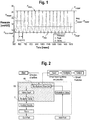
- Frequency is defined as the number of oscillations in one second, however, during a typical OPEP maneuver the rate of oscillations may not be consistent. Accordingly, frequency may be defined as the inverse of the time between oscillations (1/T), measured in Hz. This second definition calculates the frequency of each oscillation and is averaged over a period of time. Max pressure is the maximum pressure for each oscillation, typically measured in cmH 2 O.
- Min pressure is the minimum pressure for each oscillation, typically measured in cmH 2 O.
- Upper pressure is the average of the max pressures for a given time period, for example one second.
- Lower pressure is the average of min pressures for a given time period, for example one second.
- Amplitude is the difference between the upper and lower pressures.
- Mean pressure is the average of the upper and lower pressures.
- True mean pressure is the average of the entire pressure waveform for a given time period. The true mean pressure is typically lower than the means pressure because the typical pressure wave generated is not uniform, i.e., is skewed towards the min pressure.
- FIG. 1 an OPEP pressure waveform is shown with various performance characteristics.
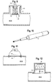
- Figure 2 illustrates in block diagram form an OPEP device, illustrated as the dashed box that encloses the internal components, configured with smart capabilities.
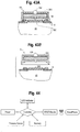
- One exemplary OPEP device 2 is the Aerobika® OPEP device, shown in FIGS. 4 , 24 , 27-30 , 47 and 48 , available from Monaghan Medical Corporation, Plattsburg, New York.
- Various OPEP devices and structures are further disclosed in U.S. Patent No. 8,985,111, issued March 24, 2015 and entitled Oscillating Positive Expiratory Pressure Device, U.S. Patent No. 8,539,951, issued September 24, 2013 and entitled Oscillating Positive Expiratory Pressure Device, U.S. Patent No.
- the OPEP device includes a housing 6 enclosing a mouthpiece chamber 48, a chamber 14, a chamber inlet 16 in communication with the mouthpiece, and one or more chamber outlets 18.
- OPEP devices permit the user to inhale and exhale, although some devices may permit exhalation only.
- the housing 6 has a front section 8, a rear section 10, and an inner casing 12, which may be separable so that the components contained therein can be periodically accessed, cleaned, or reconfigured, as required to maintain the ideal operating conditions.
- the OPEP device 2 also includes an inhalation port 20, a one-way valve 22, an adjustment mechanism 24, a restrictor member 26, a vane 28, and a variable nozzle 30, or vale assembly.
- the inner casing 12 is configured to fit within the housing 6 between the front section 8 and the rear section 10, and partially defines a chamber 14a, b, including a first chamber and a second chamber.
- First and second chamber outlets 18 are formed within the inner casing.
- the OPEP device 2 may include an adjustment mechanism 24 adapted to change the relative position of a chamber inlet 16. A user is able to conveniently adjust both the frequency and the amplitude of the OPEP therapy administered by the OPEP device 2 without opening the housing and disassembling the components of the OPEP device.
- the OPEP device 2 may be adapted for use with other or additional interfaces, such as an aerosol delivery device.
- the OPEP device 2 is equipped with an inhalation port 20 in fluid communication with the mouthpiece 4.
- the inhalation port may include a separate one-way valve 22 configured to permit a user of the OPEP device 800 both to inhale the surrounding air through the one-way valve 22 and to exhale through the chamber inlet 16, without withdrawing the mouthpiece 4 of the OPEP device 2 from the user between periods of inhalation and exhalation.
- the aforementioned commercially available aerosol delivery devices may be connected to the inhalation port 20 for the simultaneous administration of aerosol therapy (upon inhalation) and OPEP therapy (upon exhalation).
- the exhalation flow path 40 begins at the mouthpiece 4 and is directed through the mouthpiece chamber 48 toward the chamber inlet 16, which in operation may or may not be blocked by the restrictor member 26, or valve assembly which may include a valve seat and butterfly valve. After passing through the chamber inlet 16, the exhalation flow path 40 enters the first chamber 14 and makes a 180° turn toward the variable nozzle 30. After passing through an orifice of the variable nozzle, the exhalation flow path enters the second chamber 14. In the second chamber 14, the exhalation flow path 40 may exit the second chamber 41, and ultimately the housing 6, through at least one of the chamber outlets 18. It should be understood that the exhalation flow path 40 identified by the dashed line is exemplary, and that air exhaled into the OPEP device 2 may flow in any number of directions or paths as it traverses from the mouthpiece 4 to the outlets 18.
- the shaded area 50 in Figure 2 represents the internal volume, defined for example by the mouthpiece chamber 48, which becomes pressurized when the valve mechanism closes.
- the shaded area outside of the OPEP device boundary represents the "smart" features that include three operations: input, analysis and output.
- the input may come from the high pressure zone 50 as shown in Figure 2 , although it may originate from another part of the device depending on the measurement being taken or registered.
- the term "input" refers to any information that enters the smart OPEP system, and may take the form of raw data from a sensor, a command to start a process or personal data entered by the user.
- the input may be a signal from one or more input components, such as a sensor.
- a pressure sensor 52 generates an electrical signal as a function of the pressure in the system, or chamber 48.
- the pressure sensor may be used to calculate any of the performance characteristics referred to above, as well as to evaluate the user's technique.
- a sensor assembly 54 may include a housing 202 for a pressure sensor 52 placed on a printed circuit board (PCB), along with a BTLE module 56, a processor (e.g., microprocessor) 60, LED indicator 154, memory, wireless communication capabilities and a battery 58, and may communicate with an output component, for example a user's (patient, caregiver and/or other authorized user) computing device, such as a mobile device 62, including a smart phone or tablet computer.
- the assembly may be configured as a removable control module.
- a single pressure sensor 52 may provide all of the measurement requirements.
- the pressure sensor may be a differential, absolute or gauge type of sensor.
- the sensor assembly is coupled to the OPEP device, with a cover 64 disposed over the assembly.
- the input component is in considered to be in "communication" with the chamber 48 if it is able to sense or measure the pressure or flow therein, even if the input component is separated from the interior of the chamber, for example by a membrane or other substrate.
- the input component is operative to sense a flow and/or pressure and generate an input signal correlated to the flow or pressure.
- a flow sensor may be used to calculate the frequency, as well as evaluate the user's technique.
- the flow sensors may include incorporating a venturi 78 into the shape of the mouthpiece chamber ( FIG. 5A ), incorporating pitot tubes 72, which compare pressure generated by flow stagnation at the entrance of the pitot tube to that of the surrounding fluid and determine the fluid velocity ( FIG. 5B ), or using sound transmitters/receivers 74 to measure the time it takes sound to travel from transmitter 1 (74) to receiver 2 (80), and then from transmitter 2 (80) to receiver 1 (74) ( FIG.
- air flow causes displacement in a magnetic component 82, which in turn changes the inductance of a coil 84.
- the inductance of the coil is related to displacement, which may be correlated to flow rate.
- a biasing spring 86 e.g., tension or compression
- FIG. 5E air flow cause a vane 88 to move that changes the resistance of a potentiometer 90, which is related to flow rate.
- a biasing spring 92 may be include to return the vane to the "zero-flow" position when no flow is present.
- a vane 94 having for example a plurality of blades, rotates in response to a flow, with the speed of the rotation shaft 96 correlated to the proportional flow rate.
- flow 70 passes over a heater wire 98, which then begins to cool. More current is passed through the wire to maintain a constant temperature, with the amount of measured current correlated to the flow rate.
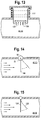
- control module 54 is not in fluid communication with the internal volume, e.g., mouthpiece chamber 48, or the OPEP device, but rather is separated by flexible membrane 200, which moves in response to changes in pressure within the device, for example the chamber 48.
- the OPEP device, or housing may be cleaned without damaging the electronic components, and those components also are not in fluid communication with the user's inspiratory and/or expiratory breath or flow.
- the flexible membrane 200 remains attached to the housing 6.
- the pressure in the OPEP chamber 48, 14a, 14b is atmospheric or ambient. As pressure in the chamber increases, an upward/outward force is applied to the membrane 200, causing it to move towards the module 54. Since a measurement chamber 202, formed between the membrane 200 and the module, is sealed with the membrane, the volume of air in the measurement chamber 202 is decreased with while the pressure in the chamber 202 is increased.
- the control module measures the pressure change inside the sealed measurement chamber and determines the pressure inside the OPEP chamber 48 (or 14a, 14b) using a conversion algorithm. During inhalation, the pressure in the chamber 48, 14a and/or 14b, becomes negative, which imparts a downward or inward force on the membrane 202.
- the control module 54 measures this pressure chamber and determines the corresponding, or actual, pressure in the chamber 48. As such, the module 54 measures pressure without being in fluid communication with the chamber 48 and the user's inspiratory/expiratory flow.
- the controller, BTLE module, LED indicator, memory sensor are in electrical contact with the power source, e.g., battery.
- the controller receives a signal from the pressure sensor and sends/receives data to/from the BTLE module, which then communicate with the mobile device 62, or other user interface and/or processor.
- the controller also sends a signal to the LED indicator 154 as required, and can save data to, and recall data from, the internal memory.
- a flex sensor 100 is shown as being disposed adjacent a high pressure cavity or zone defined by the chamber 48.
- the resistance through the flex sensor is proportional to the amount of flex applied and may be used as an indirect measurement of pressure.
- the flex sensor may be positioned on the low pressure side of a silicone membrane 102.
- the membrane 102 moves in response to a pressure increase inside the cavity or system, causing the sensor 100, cantilevered over the membrane or an actuation pad extending therefrom, to flex.
- the membrane 102 may include an actuation pad 104 that engages the flex sensor 100.
- the resistance change from the flexing maybe correlated to the pressure in the system.
- the electronic components, including the sensor are separated from the flow path by the membrane 102, which prevents contamination. Cleanliness of the flow path may be particularly important to CF patients. At the same time, the electronic components may be easily removed for cleaning and disinfecting.
- a non-contact position sensor 106 may provide either an absolute or relative position of an object, and like the flex sensor, may be used to indirectly measures pressure changes.
- Some types of non-contact position sensors are capacitive displacement sensor, ultrasonic sensors, and proximity sensors.
- the sensors may be used to measure the displacement of a moveable surface that respond to pressure changes.
- a base component 108 coupled to a silicone bellow 112 is positioned a distance "x" mm from a sensor 110.
- the base 108 attached for example with rolling bellows, is moved toward the sensor 110, e.g., cap active displacement sensor, and the distance "x" decreases. Therefore, the distance between the base 108 and the sensor 110 is inversely proportional to the pressure. If the pressure increases, the distance decrease, and vice versa.
- the sensor may also measure negative pressure, for examples as the distance "x" increases.
- an assist spring 112 such as a mechanical compression spring, may be disposed between the base 108 and sensor 110. In this way, the system is able to measure increased pressures.
- the electronic components of Figures 8A , B and 9 are separated and isolated from the flow path by the silicone membrane or bellows. In addition, the electronic components may be removable.
- a linear variable differential transformer (LVDT) 112 is shown.
- the LVDT is a contact sensor, and directly measures the linear displacement of the flexible membrane 102 or base 108 shown in the prior embodiments. The displacement may be correlated to pressure.
- a conductive membrane 114 is provided.
- the membrane is made using silicone with conductive properties. As the pressure inside of the system increases, the membrane deflects and the resistance or capacitance changes, which may be correlated to the pressure.
- a magnet 116 is configured with a spring. As the pressure inside the system changes, the distance between the magnet and Hall Effect sensor 120 may be correlated to pressure. A return spring 118 may be coupled to the magnet.
- a light curtain 122 may be used to determine the displacement of a membrane 124, which is displaced by pressure. As the pressure increases, a base or platform portion 126 of a membrane moves through the light curtain 122, with the movement correlated to pressure.
- a potentiometer vane 88 is disposed in the flow path 70.
- the amount of rotation of the vane is proportional to the flow inside the chamber, and ultimately to pressure.
- a return spring 92 is incorporated to reset the vane when zero flow is present.
- a Piezo flex sensor 128 is disposed in the flow path.
- the flex sensor bends in response to the air flow of the chamber. As the sensor bends, the resistance changes. The change of resistance may be correlated to flow rate, and pressure.
- a proximity sensor 130 is used to detect the presence of nearby objects without physical contact.
- a proximity sensor 130 is used to detect if the tip of a vane 134 is present. Every time the vane oscillates, the sensor would detect its position and the time between oscillations can be calculated. In the closed position, the vane comes within 5mm of the sensor at the highest resistance setting. A lower resistance setting will decrease the distance between the vane and the sensor.
- Another embodiment uses a proximity sensor 136 to monitor the control nozzle 30. As the valve/vane mechanism 134 opens and closes to create the pressure oscillations, the flow within the device also oscillates. When the flow is high the control nozzle 30 is in the open state, and when the flow is low the control nozzle is in the closed state. The open/closed motion of the control nozzle may be detected and converted to frequency.
- An accelerometer measures proper acceleration and can be used to calculate frequency from the vibrations as the valve/vane mechanism 26, 134 opens and closes.
- the accelerometer may be placed on the device in the location that provides the greatest vibration.
- a microphone 140 similar to the one shown in Figure 18 , may be mounted on a PCB and placed in the same location as the proximity sensor in Figures 16 and/or 17. The microphone would pick up the sound of the airflow starting and stopping, plus any mechanical contact that occurs with the oscillating mechanism.
- An LED 142 and Photo sensor 144 may be used to calculate the frequency of the oscillating mechanism.
- the LED is located on one side of the butterfly valve 146 and the photo sensor is on the other. As the valve opens, light passes through the valve seat and is measured by the photo sensor. As the valve closes, or engages the seat 148, light is blocked from reaching the photo sensor. The timing of this data can be used to calculate the frequency.
- FIG. 20 Another LED / Photo sensor arrangement is shown in Figure 20 .
- the LED is located at the far side of the vane chamber 14b, and the photo sensor is located on the side wall by one of the exhaust ports 18.
- the vane 134 pivots to one side, it blocks light from reaching the photo sensor.
- the vane pivots to the other side light from the LED is able to reach the photo sensor.
- the timing of this data may be used to calculate the frequency.
- a mobile device 62 such as a smartphone, may include an app providing an INPUT if the Smart features are not integrated into the OPEP device.
- the app may allow selection of the desired feedback and adjustment of targets and/or limits.
- Input on the user's quality of life is used to calculate a QoL score which may be correlated with DFP performance.
- Various inputs may be used to calculate a QoL score and algorithms could be tailored or adjusted for different disease types.
- User input may be performed with an auxiliary input component, such as computer device, for example a smartphone app.
- an output is defined as new information that is leaving the Smart OPEP 'system', with the information being communicated by an output component.
- the output may take the form of visual, audible, and sensory feedback, or be related to the user's quality of life and disease progress.
- a number of outputs and output components are suitable, including a visual output component, which may be easily integrated into the Smart OPEP device and allow several levels of feedback.
- a visual output component which may be easily integrated into the Smart OPEP device and allow several levels of feedback.
- an array 150 of three (3) LEDs 152 each with a different colour may indicate if the input is low, high, or acceptable.
- a single tri-colour LED 154 may also be used. If more than three (3) discreet states of feedback are required, then a LED bar graph 156 may be used.
- Audible and sensory/tactile (vibration) outputs and output components may also be used to provide feedback to the user. For example, sound or vibration occurs while the input is within the acceptable range, or if the input exceeds a specified limit.
- a mobile device 62 may function as the output component and provide an interface with a smartphone app as an output if the Smart features are not integrated into the OPEP device.
- the app could display real-time performance characteristics, data trends, or games that motivate the user to complete a session.
- This feature provides feedback to the user based on specific performance targets. For example, if the mean pressure is to be within 10 to 15 cmH2O, this feature would notify the user that their mean pressure is too high, too low, or acceptable.
- the performance targets can be set by the patient or health care provider, or default to limits based on generally accepted treatment protocols.
- a sensor 154 which may include without limitation any one of the sensors previously disclosed herein, or combinations thereof, the ability to process raw data, including for example a processor 158, an output component 150, 154, 156 to display feedback, and if necessary, the ability to enter performance limits manually.
- the location of the sensor may change depending on the type of sensor selected or the performance characteristic being measured as disclosed herein with respect to various embodiments.
- the flow chart for this feature is shown in Figure 25 .
- the dashed area represents an integrated embodiment that does not allow the target limits to be adjusted and in this case provides feedback on the mean pressure.
- the user first selects the type of feedback.
- the " Get Type & Set Type" define the performance characteristic to be analyzed.
- the user decides if custom targets are to be used and enters the limits. If not, default limits are set based on the performance characteristic selected.
- the sensor 154 begins sending raw data and the selected performance characteristic is calculated.
- a series of decisions are made based on the calculated value of the performance characteristic. If the value is greater than the upper limit, then the output is high. If the value is less than the lower limit, then the output is low. If the value is neither, than the output is OK.
- the flow chart checks if the user has selected to end the feedback. If not, then the cycle repeats. The above logic provides 3 discreet states of feedback. If required, additional logic could be added to provide a finer resolution to the feedback.
- the analysis may either be completed using a processor 158, e.g., a microcontroller, embedded in the PCB, or may be performed using an external computing device, such as mobile device, including a smartphone or tablet.
- a processor 158 e.g., a microcontroller, embedded in the PCB
- frequency may be determined from any sensor, however, pressure outputs require a pressure sensor (either direct or indirect).
- processing techniques such as: Peak-to-Peak time, Fourier analysis, or Auto-correlation may be used.
- Figure 1 illustrates an example of a pressure waveform that has been processed using a Peak-to-Peak technique.
- the input is a sound signal it can be averaged to simplify the waveform.
- the simpler waveform may then be processed in the same way as a pressure signal to determine frequency.
- the raw sound data bars
- the Root Sum of Squares technique has been averaged using the Root Sum of Squares technique and the result is shown by the line.
- Each peak (dot) is then identified and the time between peaks is calculated and used to determine the frequency.
- the output for this feature can be visual 160, audible 162, or sensory 164, and can be integrated into the device.
- An example of an integrated solution is shown in Figures 4 , and 27-29 .
- an integrated solution would not provide for the selection of the performance characteristics or adjustment of the performance limits.
- the integrated solution may provide a user interface permitting such selection and adjustment, for example through a keypad, buttons or touchscreen.
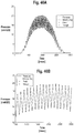
- the algorithm for calculating the performance characteristics including recording the raw data, filtering or smoothing the raw data to remove any noise, which may be accomplished by known techniques including a moving average, Butterworth filter, Fourier filter or Kernel filter.
- the direction of the slope is determined using the filtered/smoothed data, whether positive or negative. Slope changes between positive and negative are identified and labelled as a peak, with changes from negative to positive labeled as a trough. For each peak and trough, the timestamp and pressure value is logged. Exemplary data is shown in FIGS. 46A and B . Using the time and pressure value for each peak and trough, the frequency, amplitude and mean pressures are calculated.
- the computing device such as a mobile device including a smartphone 62, may function as the output device (and also the manual input (auxiliary input component) and analysis source).
- the Smart OPEP communicates with the smartphone via a wireless protocol such as Bluetooth as shown in Figure 30 .
- An application (app) will allow the user to input the desired performance characteristic and set the limits if necessary ( Figure 21 ).
- An output screen 170 will display the target limits and provide feedback to the user (e.g., too high, too low, or ok) as shown in Figures 21 , 23 and 32 .
- FIG. 33 another possible output for this feature may be to turn the session into a game.
- the bird 180 represents the current performance characteristic value, which must pass through the pipes 182 without going outside the limits (upper and lower) 184, 186. If both frequency and pressure targets are required, care must be taken to ensure that the user is not overwhelmed with the feedback and is able to compensate their breathing technique to meet the required targets.
- a custom output graphic could be developed to aid the user in controlling two performance characteristics, such as frequency and pressure.
- Figure 34 illustrates an example of a simple game that helps aid the user in controlling both frequency and pressure. The goal of the game is to get the ball into the hole and the current location of the ball is dependent on the frequency and pressure.
- the user first wakes the OPEP device, for example by pushing a manual button or automatically as the device is picked up by using an accelerometer. Once awake, the device pairs with a mobile device, such as a smart phone, if available. If a mobile device is available, an application may be opened and any previous data saved in memory may be downloaded in the mobile device. The user may be prompted to modify performance targets if desired. Once performance targets are set, the application opens the feedback screen so that the user may monitor their performance throughout the treatment. If a smart phone is not available, the previous performance targets are used, and the data is saved internally. The OPEP device begins monitoring for positive pressure.
- a mobile device such as a smart phone
- the device If at any point during treatment, the device does not detect a positive pressure change for a specified amount of time, the device saves any treatment data to either the mobile device or the internal memory and enters a standby mode to conserve power. If positive pressure is detected, the OPEP device will begin to measure the pressure (positive and negative), calculate the performance characteristics such as frequency, amplitude and mean pressures and provide feedback to the user regarding their technique.
- Data logged by the OPEP may be transferred to an external device, such as a smartphone, tablet, personal computer, etc. If such an external device is unavailable, the data may be stored internally in the OPEP in a data storage module or other memory and transferred upon the next syncing between the OPEP and external device. Software may accompany the OPEP to implement the data transfer and analysis.
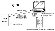
- data may be wirelessly communicated to a smart phone, local computing device and/or remote computing device to interpret and act on the raw sensor data.
- the smart OPEP includes circuitry for transmitting raw sensor data in real-time to a local device, such as a smart phone.
- the smart phone may display graphics or instructions to the user and implement processing software to interpret and act on the raw data.
- the smart phone may include software that filters and processes the raw sensor data and outputs the relevant status information contained in the raw sensor data to a display on the smart phone.
- the smart phone or other local computing device may alternatively use its local resources to contact a remote database or server to retrieve processing instructions or to forward the raw sensor data for remote processing and interpretation, and to receive the processed and interpreted sensor data back from the remote server for display to the user or a caregiver that is with the user of the smart OPEP.
- proactive operations relating to the smart OPEP may be actively managed and controlled. For example, if the smart phone or other local computer in proximity to the smart OPEP determines that the sensor data indicates the end of treatment has been reached, or that further treatment is needed, the smart phone or other local computing device may communicate such information directly to the patient.
- a remote server in communication with the smart phone, or in direct communication with the smart OPEP via a communication network can supply the information and instructions to the patient/user.
- real-time data gathered in the smart OPEP and relayed via to the smart phone to the remote server may trigger the remote server to track down and notify a physician or supervising caregiver regarding a problem with the particular treatment session or a pattern that has developed over time based on past treatment sessions for the particular user.
- the remote server may generate alerts to send via text, email or other electronic communication medium to the user, the user's physician or other caregiver.
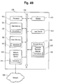
- the electronic circuitry in the smart OPEP may include some or all of the capabilities of a computer in communication with a network and/or directly with other computers.
- the computer 500 may include a processor 502, a storage device 516, a display or other output device 510, an input device 512, and a network interface device 520, all connected via a bus 508.
- a battery 503 is coupled to and powers the computer.
- the computer may communicate with the network.
- the processor 502 represents a central processing unit of any type of architecture, such as a CISC (Complex Instruction Set Computing), RISC (Reduced Instruction Set Computing), VLIW (Very Long Instruction Word), or a hybrid architecture, although any appropriate processor may be used.
- the processor 502 executes instructions and includes that portion of the computer 500 that controls the operation of the entire computer.
- the processor 502 typically includes a control unit that organizes data and program storage in memory and transfers data and other information between the various parts of the computer 500.
- the processor 502 receives input data from the input device 512 and the network 526 reads and stores instructions (for example processor executable code) 524 and data in the main memory 504, such as random access memory (RAM), static memory 506, such as read only memory (ROM), and the storage device 516.
- the processor 502 may present data to a user via the output device 510.
- the computer 500 is shown to contain only a single processor 502 and a single bus 508, the disclosed embodiment applies equally to computers that may have multiple processors and to computers that may have multiple busses with some or all performing different functions in different ways.
- the storage device 516 represents one or more mechanisms for storing data.
- the storage device 516 may include a computer readable medium 522 such as read-only memory (ROM), RAM, non-volatile storage media, optical storage media, flash memory devices, and/or other machine-readable media.
- ROM read-only memory
- RAM random access memory
- the storage device 516 may include a controller (not shown) and a computer readable medium 522 having instructions 524 capable of being executed on the processor 502 to carry out the functions described above with reference to processing sensor data, displaying the sensor data or instructions based on the sensor data, controlling aspects of the smart OPEP to alter its operation, or contacting third parties or other remotely located resources to provide update information to, or retrieve data from those remotely located resources.
- some or all of the functions are carried out via hardware in lieu of a processor-based system.
- the controller is a web browser, but in other embodiments the controller may be a database system, a file system, an electronic mail system, a media manager, an image manager, or may include any other functions capable of accessing data items.
- the storage device 516 may also contain additional software and data (not shown), which is not necessary to understand the invention.
- the output device 510 is that part of the computer 500 that displays output to the user.
- the output device 510 may be a liquid crystal display (LCD) well-known in the art of computer hardware.
- the output device 510 may be replaced with a gas or plasma-based flat-panel display or a traditional cathode-ray tube (CRT) display.
- CTR cathode-ray tube
- any appropriate display device may be used.
- only one output device 510 is shown, in other embodiments any number of output devices of different types, or of the same type, may be present.
- the output device 510 displays a user interface.
- the input device 512 may be a keyboard, mouse or other pointing device, trackball, touchpad, touch screen, keypad, microphone, voice recognition device, or any other appropriate mechanism for the user to input data to the computer 500 and manipulate the user interface previously discussed. Although only one input device 512 is shown, in another embodiment any number and type of input devices may be present.
- the network interface device 520 provides connectivity from the computer 500 to the network 526 through any suitable communications protocol.
- the network interface device 520 sends and receives data items from the network 526 via a wireless or wired transceiver 514.
- the transceiver 514 may be a cellular frequency, radio frequency (RF), infrared (IR) or any of a number of known wireless or wired transmission systems capable of communicating with a network 526 or other smart devices 102 having some or all of the features of the example computer of FIGS. 83 and 84.
- the bus 508 may represent one or more busses, e.g., USB, PCI, ISA (Industry Standard Architecture), X-Bus, EISA (Extended Industry Standard Architecture), or any other appropriate bus and/or bridge (also called a bus controller).
- busses e.g., USB, PCI, ISA (Industry Standard Architecture), X-Bus, EISA (Extended Industry Standard Architecture), or any other appropriate bus and/or bridge (also called a bus controller).
- the computer 500 may be implemented using any suitable hardware and/or software, such as a personal computer or other electronic computing device.
- the computer 500 may be a portable computer, laptop, tablet or notebook computers, smart phones, PDAs, pocket computers, appliances, telephones, and mainframe computers are examples of other possible configurations of the computer 500.
- the network 526 may be any suitable network and may support any appropriate protocol suitable for communication to the computer 500.
- the network 526 may support wireless communications.
- the network 526 may support hard-wired communications, such as a telephone line or cable.
- the network 526 may support the Ethernet IEEE (Institute of Electrical and Electronics Engineers) 802.3x specification.
- the network 526 may be the Internet and may support IP (Internet Protocol).
- the network 526 may be a LAN or a WAN. In another embodiment, the network 526 may be a hotspot service provider network. In another embodiment, the network 526 may be an intranet. In another embodiment, the network 526 may be a GPRS (General Packet Radio Service) network. In another embodiment, the network 526 may be any appropriate cellular data network or cell-based radio network technology. In another embodiment, the network 526 may be an IEEE 802.11 wireless network. In still another embodiment, the network 526 may be any suitable network or combination of networks. Although one network 526 is shown, in other embodiments any number of networks (of the same or different types) may be present.
- GPRS General Packet Radio Service
- the computing device In the case of program code execution on programmable computers, the computing device generally includes a processor, a storage medium readable by the processor (including volatile and non-volatile memory and/or storage elements), at least one input device, and at least one output device.
- One or more programs may implement or use the processes described in connection with the presently disclosed subject matter, e.g., through the use of an API, reusable controls, or the like. Such programs may be implemented in a high level procedural or object-oriented programming language to communicate with a computer system. However, the program(s) can be implemented in assembly or machine language, if desired. In any case, the language may be a compiled or interpreted language and it may be combined with hardware implementations.
- exemplary embodiments may refer to using aspects of the presently disclosed subject matter in the context of one or more stand-alone computer systems, the subject matter is not so limited, but rather may be implemented in connection with any computing environment, such as a network or distributed computing environment. Still further, aspects of the presently disclosed subject matter may be implemented in or across a plurality of processing chips or devices, and storage may similarly be spread across a plurality of devices. Such devices might include personal computers, network servers, and handheld devices, for example.
- a controller which may be located on or inside the various embodiments of the smart OPEP described herein, is in communication with one or more sensors, switches and or gauges that are tracking or controlling operation of the smart OPEP.
- the controller may store data gathered in a memory, integrated into the controller or implemented as a discrete non-volatile memory located in the smart OPEP, for later download to a receiving device, or may transmit data to a receiving device in real-time. Additionally, the controller may perform some processing of the gathered data from the sensors, or it may store and transmit raw data.
- RF transmitter and/or receiver modules may be associated with the controller on the smart OPEP to communicate with remote hand-held or fixed computing devices in real-time or at a later time when the smart OPEP is in communication range of a communication network to the remote hand-held or fixed location computing devices.
- the controller may include one or more of the features of the computer system 500 shown in FIG. 83. Additionally, the one or more sensors, switches or gauges may be in wired or wireless communication with the controller.
- the controller circuitry is omitted from some illustrations, however a controller or other processing agent capable of at least managing the routing or storing of data from the smart OPEP is contemplated in one version of these embodiments.
- the smart OPEP may not include an onboard processor and the various sensors, gauges and switches of a particular embodiment may wirelessly communicate directly with a remotely located controller or other processing device, such as a handheld device or remote server. Data gathered by a controller or other processing device may be compared to expected or pre-programmed values in the local controller memory or other remote location to provide the basis for feedback on whether desired performance or therapy is taking place.
- the controller is a more sophisticated and includes more of the computer 500 elements described in FIG. 49 , then this processing may all be local to the smart OPEP.
- the data may simply be date/time stamped, and may also be appended with a unique device ID, and stored locally or remotely for later processing. In one embodiment, the data may further be locally or remotely stamped with a unique device or patient identifier.
- the patient or HCP may be notified if a pressure characteristic is exceeded.
- the main purpose for this feature is to ensure patient safety and is a simplified version of the previous feature. For example, OPEP therapy is used post-operatively and patients may need to remain below a certain pressure.
- the flow chart in Figure 35 is similar to the flow chart of Figure 25 , but only contains an upper limit. Any of the outputs discussed above may be used in this feature, such as visual, audible, vibration, or a smartphone display.
- Previous features may only inform the user if the input is high, low, or acceptable.
- An additional feature provides quantitative real-time feedback of the desired performance characteristic.
- the inputs can be analyzed to determine:
- a computer device such as a laptop, smartphone, or tablet, or other separate device with a display is required.
- DFP data can be displayed over time and the user can retrieve and display the data by some temporal component, including for example and without limitation day, week, month, year, or all time. This allows the user to quickly visualize trends in the performance.
- the OPEP device provides five (5) resistance settings which change the frequency, amplitude and mean pressure performance. For a given flow rate, increasing the resistance setting increases the frequency and pressure characteristics.
- the correct resistance setting will produce an Inspiratory:Expiratory ratio (I:E ratio) of 1:3 or 1:4 for 10 - 20 min without excess fatigue. Therefore, the input will be used to identify the start and end of the inspiratory and expiratory cycles.
- Some possible inputs include a flow sensor, pressure sensor, or microphone.
- a flow sensor may be placed in the mouthpiece and used to determine the I:E ratio.
- a single flow sensor, placed at location 1 in Figure 36 would need to be able to measure flow in both directions. It would also be possible to use two (2) one-way flow sensors: one in the location 1 for exhalation and one in location 2, as shown in Figure 36 , for inhalation.
- a pressure sensor may be used to calculate the I:E ratio. If the pressure is negative then the flow is inspiratory, and if the pressure is positive then the flow is expiratory.
- the pressure sensor may be positioned as shown in Figure 24 .
- two (2) microphones may to be used for the calculation of the I:E ratio, similar to the dual flow sensors shown in Figure 36 .
- a single microphone would only be able to identify if flow is occurring, and not if it is inspiratory or expiratory.
- An output component may be embedded in the device and be either visual, audible, or tactile as shown in Figures 27-28 , or, the output may be shown on a separate device such as a smartphone, or other computer device or screen.
- This feature will analyze previous DFP data and make setting recommendations. This feature may calculate the I:E Ratio for each breath and then calculate the average I:E Ratio for a session. Based on the average I:E Ratio, this feature would make a setting change recommendation using the logic shown in Figure 37 and/or referred to above.
- This feature will provide the user with training and coaching on proper technique for performing an OPEP maneuver based on the IFU, and may be updated for other devices.
- this feature may take the form of an app, and will communicate with the OPEP device via BTLE (see Figure 4 for more details).
- a proper OPEP maneuver relies on several variables, such as I:E Ratio, frequency, pressure, and setting. These inputs have been previously discussed.
- the ideal OPEP maneuver follows these steps: Inhale slowly, taking a deeper breath than normal but not filling the lungs, hold your breath and exhale actively.
- the app needs to learn the user's breathing pattern. This is done during the initial setup or training session and could be re-evaluated if the user's performance changes.
- the user would inhale normally through the device in order to calculate their baseline inspiratory pressure, or IP Tidal , or Tidal Volume (TV).
- IP max maximum inspiratory pressure
- IC Inspiratory Capacity
- the app would then calculate the target inspiratory pressure (IP target ) or volume for step #1 which is more than IP tidal (or the Tidal Volume) and less than the IP max (or Inspiratory Capacity).
- IP target target inspiratory pressure
- volume for step #1 which is more than IP tidal (or the Tidal Volume) and less than the IP max (or Inspiratory Capacity).
- IP target inspiratory pressure or target inspiratory volume
- a starting point for the IP target (or target inspiratory volume) would be the average of IP tidal and IP max (or the TV and the IC).
- Frequency and pressures should be within target range and exhalation should last 3-4 times longer than inhalation. Exhaling actively is a subjective description of the OPEP maneuver, therefore, the app will calculate the frequency, mean pressure and I:E ratio in real-time, and use that information and data to determine if the proper technique is being achieved.
- the output of this coaching feature will guide the user toward the correct OPEP technique based on the user's breathing pattern and specific performance targets. If any of steps above are not performed correctly, the app will make suggestions to change the user's technique. For example, if the user doesn't hold their breath before exhaling, the app would offer a reminder. In another example, the app may suggest that the user increase their flow rate because the mean pressure is too low and is not within the accepted limits. To declare the user "trained", the app may require the user to demonstrate a proper OPEP maneuver several times. The app could also play audio of a proper OPEP maneuver, which may assist the user in exhaling actively. The app may also include training videos explaining the proper technique and examples of people performing proper OPEP maneuvers. The app may also notify the user's healthcare provider (HCP) if proper technique isn't being completed.
- HCP healthcare provider
- the Smart OPEP device can assist the user in following the correct therapy regime. Session Assist features aid the user or HCP in completing an OPEP session. For the first time user, an OPEP session can be confusing and complicated. The user needs to count the number of breaths, remember proper technique, remember when to perform 'Huff' coughs, and etc. For example, the the Aerobika® OPEP device IFU recommends the following steps: perform 10-20 OPEP maneuvers or breaths, after at least 10 breaths, perform 2-3 'Huff' coughs, repeat for 10-20 minutes twice / day on a regular base, increase to 3-4 times / day if needed.
- this feature would count the number of breaths and provide feedback to the user, either with the number remaining or the number completed. The app would then remind the user to perform 'Huff' coughs after the appropriate number of breaths, and then repeat the breath counting / huff cough cycle for 10-20 minutes. The user may input the total number of breaths to complete or total session time as a goal and track progress. The Session Assist feature would also track the number of sessions per day, which can be used to determine the user's progress or quality of life.
- This feature transforms quantitative data into qualitative data that is easier for the user, HCP, or payer to understand.
- QoL Quality of Life
- Various inputs may be used to calculate a QoL score which will be correlated with DFP performance.
- Inputs may be both qualitative and quantitative.
- Algorithms may be tailored or adjusted for different disease types.
- the objective is to calculate a QoL score that evolves over time as the user's condition improves or worsens.
- the user completes a questionnaire and a baseline QoL score is computed.
- the application may also calculate (or integrate with another app or device such as a FitBit) the number of steps taken per day and use this information to adjust the QoL score.
- the app would determine a relationship between the QoL score and the measurements in the DFP history. This would require a period of time when the app is 'learning' how the two (2) variables relate.
- QoL 5.6xMP-6.8 as shown in Figure 39 .
- This feature provides feedback to the user about the device itself.
- Several options exist including notifying the user, HCP or payer that the device needs to be replaced. This may take the form of a reminder in the app, or could lockout features until a new lot number or serial number is entered.
- the feedback may also include notifying the user when the device needs to be cleaned. Cleaning notifications could be based on the number of sessions between cleaning or changes in device performance over time.
- a stakeholder is defined as an individual or organization, outside the patient's immediate family, that has an interest in the patient's condition, treatment, and progress.
- Stakeholders may be the patient's doctor, respiratory therapists, hospital, or insurance company.
- Some examples of stakeholder updates include: updating an insurance company with the user's usage data to monitor patient adherence and/or updating HCP with user's progress since last visit, usage data, and QoL score.
- a device that automatically adjusts the resistance to keep the selected performance characteristic (e.g., pressure (amplitude) and/or frequency) in the desired range.
- the range and/or performance characteristic to be controlled may be pre-programmed into the device or be inputted by the user as described above.
- the microprocessor would receive data from the sensor and an algorithm would decide how to adjust the device.
- the microprocessor would then give a command to a motor 190 and the motor would physically perform the adjustment of a control component, such as the valve seat 148 or orientation of the chamber inlet.
- the encoder 192 would confirm the position of the motor and provide that information back to the microprocessor. This would improve user adherence since all the user needs to do is exhale into the device.
- the device will automatically set and control the resistance setting to achieve the desired therapy. Another option would be to program into the algorithm variations in frequency or pressure as some research has shown to be beneficial.
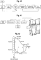
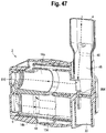
- one embodiment includes a flow sensor, which makes it possible to evaluate the patient's lung health by turning off the oscillations and allowing the device to operate like a spirometer.
- the flow sensor would need to be able to measure flow in both directions (inspiratory and expiratory).
- An algorithm take the flow being measured and generate a flow-volume (FV) loop shown below in Figure 42 . From the FV Loop, various parameters may be calculated and fed back to the patient.
- FV flow-volume
Landscapes
- Health & Medical Sciences (AREA)
- Life Sciences & Earth Sciences (AREA)
- General Health & Medical Sciences (AREA)
- Engineering & Computer Science (AREA)
- Biomedical Technology (AREA)
- Heart & Thoracic Surgery (AREA)
- Pulmonology (AREA)
- Animal Behavior & Ethology (AREA)
- Public Health (AREA)
- Veterinary Medicine (AREA)
- Anesthesiology (AREA)
- Hematology (AREA)
- Emergency Medicine (AREA)
- Physiology (AREA)
- Physics & Mathematics (AREA)
- Biophysics (AREA)
- Pathology (AREA)
- Medical Informatics (AREA)
- Molecular Biology (AREA)
- Surgery (AREA)
- Measurement Of The Respiration, Hearing Ability, Form, And Blood Characteristics Of Living Organisms (AREA)
- User Interface Of Digital Computer (AREA)
- Infusion, Injection, And Reservoir Apparatuses (AREA)
Description
- This application claims the benefit of
U.S. Provisional Application No. 62/359,970, filed July 8, 2016 - The embodiments disclosed herein relate generally to a smart oscillating positive expiratory pressure device, and to methods for the use and assembly thereof.
- Chronic obstructive pulmonary disease (COPD) and cystic fibrosis (CF) may cause an increase in the work of breathing that leads to dyspnea, respiratory muscle fatigue and general discomfort. Oscillating positive expiratory pressure (OPEP) treatments may be used as a drug-free way to clear excess mucus from the lungs of COPD and CF patients. OPEP may also be used post-operatively to reduce the risk of post-operative pulmonary complications. Typically, OPEP devices provide minimal feedback to the user or caregiver about the performance and/or effectiveness of the device during a treatment session. In addition, a large percentage (60%) of COPD patients do not adhere to prescribed therapy, with hospital systems carrying the burden of non-compliant patients that return to the hospital within 30 days. In addition, OPEP devices typically do not provide feedback regarding therapy adherence, progress tracking or proper usage technique.
- The invention is defined in the appended claims.
- Briefly stated, in one embodiment, a smart OPEP device provides feedback to the user (patient or caregiver) regarding the frequency, mean pressure and amplitude of the pressure oscillations generated during a treatment session. In addition, data and information gathered regarding the performance of the OPEP device may be archived and analyzed to provide an overview of the user's progress, which may be made available to health care providers and insurers, for example, to monitor treatment adherence. Patient specific data may be provided to monitor trends over time. Performance targets and /or limits may be set to assist the user in achieving correct techniques, and treatment effectiveness may be evaluated by surveying the patient's quality of life and linking it to performance. In addition, with performance characteristics being measured, the user may set up the device, and the user may be motivated by various feedback including counting breaths or by playing games based on the measurements.
- The present embodiments, together with further objects and advantages, will be best understood by reference to the following detailed description taken in conjunction with the accompanying drawings.
-
-
FIG. 1 is a graph of an OPEP pressure waveform that identifies various performance characteristics. -
FIG. 2 is a block diagram of an OPEP device with smart capabilities. -
FIG. 3 is a perspective view of a pressure sensor. -
FIG. 4 is a partial, exploded perspective view of one embodiment of a smart OPEP. -
FIGS. 5A-G show various flow sensors. -
FIG. 6 is a perspective view of a flex sensor. -
FIGS. 7A and B are partial cross-sectional views of an OPEP device with a flex sensor in an un-flexed and flexed configuration respectively. -
FIGS. 8A and B are partial cross-sectional views of an OPEP device with a non-contact position sensor in first and second pressure configurations respectively. -
FIG. 9 is a partial cross-sectional view of an OPEP device with a spring assisted non-contact position sensor. -
FIG. 10 is a perspective view of a linear variable differential transformer (LVDT). -
FIG. 11 is a partial cross-sectional view of an OPEP device with a conductive membrane. -
FIG. 12 is a partial cross-sectional view of an OPEP device with a Hall Effect sensor. -
FIG. 13 is a partial cross-sectional view of an OPEP device with a light curtain sensor. -
FIG. 14 is a partial cross-sectional view of an OPEP device with a potentiometer vane. -
FIG. 15 is a partial cross-sectional view of an OPEP device with a piezo flex sensor. -
FIG. 16 is a partial cross-sectional view of an OPEP device with a proximity sensor with a vane in a closed position. -
FIG. 17 is a series of exploded perspective views of an OPEP device with a proximity sensor. -
FIG.18 is a perspective view of a PCB microphone. -
FIG. 19 is a partial cross-sectional view of an OPEP device with a LED/Photo sensor. -
FIG. 20 is a partial cross-sectional view of an OPEP device with another embodiment of a LED/Photo sensor. -
FIG. 21 is a view of a user interface with an input screen. -
FIG. 22 shows various LED outputs. -
FIG. 23 is a view of a user interface with an output screen. -
FIG. 24 is a partial view of a layout for a smart OPEP device. -
FIG. 25 is a flow chart for performance targets for an OPEP device. -
FIG. 26 is an exemplary graph of a sound signal. -
FIG. 27 shows partial exploded and non-exploded views of an OPEP device with an LED output. -
FIG. 28 is a view of an LED output. -
FIG. 29 is perspective view of an OPEP device with an auditory or vibratory/tactile output. -
FIG. 30 is a schematic of a system with an OPEP device communicating with a user interface via a wireless protocol. -
FIG. 31 is a flow chart for a smart OPEP algorithm. -
FIG. 32 are examples of output screens for a user interface. -
FIG. 33 is a view of a user interface with one embodiment of an output game. -
FIG. 34 is a view of a user interface with one embodiment of an output game providing feedback on pressure and frequency. -
FIG. 35 is a flow chart for performance limits. -
FIG. 36 is a partial, perspective view of an OPEP device with dual flow sensors. -
FIG. 37 is a flow chart for analyzing an I:E ratio. -
FIG. 38 is a graph showing an I:E ratio. -
FIG. 39 is a graph showing the linear regression of mean pressure v. QoL score. -
FIG. 40 is a flow chart for determining a relationship between a QoL score and measurements taken from the OPEP device. -
FIG. 41 is a flow chart and partial cross-sectional view of an active OPEP device. -
FIG. 42 is a graph of a flow-volume loop. -
FIGS. 43A and B are partial cross-sectional views of control module in an installed and uninstalled position. -
FIG. 44 is a block diagram of a smart OPEP system. -
FIG. 45 is a flow chart of a treatment sequence using a smart OPEP system. -
FIGS. 46A and B are exemplary graphs of pressure v. time data gathered from a smart OPEP device. -
FIGS. 47 and48 are cross-sectional views of an OPEP device shown with and without internal components respectively. -
FIG. 49 is a schematic illustrating the computer structure. -
FIG. 50 is a schematic illustration of a communication system. - It should be understood that the term "plurality," as used herein, means two or more. The term "coupled" means connected to or engaged with, whether directly or indirectly, for example with an intervening member, and does not require the engagement to be fixed or permanent, although it may be fixed or permanent. It should be understood that the use of numerical terms "first," "second," "third," etc., as used herein does not refer to any particular sequence or order of components. It should be understood that the term "user" and "patient" as used herein refers to any user, including pediatric, adolescent or adult humans, and/or animals.
- The term "smart" refers to features that follow the general format of having an input, where information is entered into the system, analysis, where the system acts on or modifies the information, and an output, wherein new information leaves the system. The phrase "performance characteristics" refers to measurements, such as frequency or amplitude, which quantify how well a device is functioning. Frequency is defined as the number of oscillations in one second, however, during a typical OPEP maneuver the rate of oscillations may not be consistent. Accordingly, frequency may be defined as the inverse of the time between oscillations (1/T), measured in Hz. This second definition calculates the frequency of each oscillation and is averaged over a period of time. Max pressure is the maximum pressure for each oscillation, typically measured in cmH2O. Min pressure is the minimum pressure for each oscillation, typically measured in cmH2O. Upper pressure is the average of the max pressures for a given time period, for example one second. Lower pressure is the average of min pressures for a given time period, for example one second. Amplitude is the difference between the upper and lower pressures. Mean pressure is the average of the upper and lower pressures. True mean pressure is the average of the entire pressure waveform for a given time period. The true mean pressure is typically lower than the means pressure because the typical pressure wave generated is not uniform, i.e., is skewed towards the min pressure.
- Referring to
Figure 1 , an OPEP pressure waveform is shown with various performance characteristics.Figure 2 illustrates in block diagram form an OPEP device, illustrated as the dashed box that encloses the internal components, configured with smart capabilities. Oneexemplary OPEP device 2 is the Aerobika® OPEP device, shown inFIGS. 4 ,24 ,27-30 ,47 and 48 , available from Monaghan Medical Corporation, Plattsburg, New York. Various OPEP devices and structures are further disclosed inU.S. Patent No. 8,985,111, issued March 24, 2015 and entitled Oscillating Positive Expiratory Pressure Device,U.S. Patent No. 8,539,951, issued September 24, 2013 and entitled Oscillating Positive Expiratory Pressure Device,U.S. Patent No. 9,220,855, issued December 29, 2015 U.S. Pub. 2012/0304988, Published December 6, 2012 and entitled Oscillating Positive Expiratory Pressure DeviceU.S. Pub. 2015/0297848, Published October 22, 2015 and entitled Oscillating Positive Expiratory Pressure Device, andU.S. Pub. 2015/0053209, Published February 26, 2015 and entitled Oscillating Positive Expiratory Pressure Device. It should be understood that other OPEP devices may be configured with other components that create pressure oscillations. - A user, such as a patient, interacts with the
OPEP device 2 via amouthpiece 4. The OPEP device includes ahousing 6 enclosing amouthpiece chamber 48, achamber 14, achamber inlet 16 in communication with the mouthpiece, and one ormore chamber outlets 18. Typically, OPEP devices permit the user to inhale and exhale, although some devices may permit exhalation only. Thehousing 6 has afront section 8, arear section 10, and aninner casing 12, which may be separable so that the components contained therein can be periodically accessed, cleaned, or reconfigured, as required to maintain the ideal operating conditions. - The
OPEP device 2 also includes aninhalation port 20, a one-way valve 22, anadjustment mechanism 24, arestrictor member 26, avane 28, and avariable nozzle 30, or vale assembly. As seen inFIGS. 47 and48 , theinner casing 12 is configured to fit within thehousing 6 between thefront section 8 and therear section 10, and partially defines achamber 14a, b, including a first chamber and a second chamber. First andsecond chamber outlets 18 are formed within the inner casing. TheOPEP device 2 may include anadjustment mechanism 24 adapted to change the relative position of achamber inlet 16. A user is able to conveniently adjust both the frequency and the amplitude of the OPEP therapy administered by theOPEP device 2 without opening the housing and disassembling the components of the OPEP device. - The
OPEP device 2 may be adapted for use with other or additional interfaces, such as an aerosol delivery device. In this regard, theOPEP device 2 is equipped with aninhalation port 20 in fluid communication with themouthpiece 4. As noted above, the inhalation port may include a separate one-way valve 22 configured to permit a user of theOPEP device 800 both to inhale the surrounding air through the one-way valve 22 and to exhale through thechamber inlet 16, without withdrawing themouthpiece 4 of theOPEP device 2 from the user between periods of inhalation and exhalation. In addition, the aforementioned commercially available aerosol delivery devices may be connected to theinhalation port 20 for the simultaneous administration of aerosol therapy (upon inhalation) and OPEP therapy (upon exhalation). - The
exhalation flow path 40 begins at themouthpiece 4 and is directed through themouthpiece chamber 48 toward thechamber inlet 16, which in operation may or may not be blocked by therestrictor member 26, or valve assembly which may include a valve seat and butterfly valve. After passing through thechamber inlet 16, theexhalation flow path 40 enters thefirst chamber 14 and makes a 180° turn toward thevariable nozzle 30. After passing through an orifice of the variable nozzle, the exhalation flow path enters thesecond chamber 14. In thesecond chamber 14, theexhalation flow path 40 may exit the second chamber 41, and ultimately thehousing 6, through at least one of thechamber outlets 18. It should be understood that theexhalation flow path 40 identified by the dashed line is exemplary, and that air exhaled into theOPEP device 2 may flow in any number of directions or paths as it traverses from themouthpiece 4 to theoutlets 18. - The shaded
area 50 inFigure 2 represents the internal volume, defined for example by themouthpiece chamber 48, which becomes pressurized when the valve mechanism closes. The shaded area outside of the OPEP device boundary represents the "smart" features that include three operations: input, analysis and output. The input may come from thehigh pressure zone 50 as shown inFigure 2 , although it may originate from another part of the device depending on the measurement being taken or registered. - The term "input" refers to any information that enters the smart OPEP system, and may take the form of raw data from a sensor, a command to start a process or personal data entered by the user. For example, the input may be a signal from one or more input components, such as a sensor. For example, as shown in
Figures 3 and 4 , apressure sensor 52 generates an electrical signal as a function of the pressure in the system, orchamber 48. The pressure sensor may be used to calculate any of the performance characteristics referred to above, as well as to evaluate the user's technique. Asensor assembly 54 may include ahousing 202 for apressure sensor 52 placed on a printed circuit board (PCB), along with aBTLE module 56, a processor (e.g., microprocessor) 60,LED indicator 154, memory, wireless communication capabilities and abattery 58, and may communicate with an output component, for example a user's (patient, caregiver and/or other authorized user) computing device, such as amobile device 62, including a smart phone or tablet computer. The assembly may be configured as a removable control module. Asingle pressure sensor 52 may provide all of the measurement requirements. The pressure sensor may be a differential, absolute or gauge type of sensor. The sensor assembly is coupled to the OPEP device, with acover 64 disposed over the assembly. The input component is in considered to be in "communication" with thechamber 48 if it is able to sense or measure the pressure or flow therein, even if the input component is separated from the interior of the chamber, for example by a membrane or other substrate. The input component is operative to sense a flow and/or pressure and generate an input signal correlated to the flow or pressure. - Referring to
Figures 5A-G , various flow sensors are shown that generate an electrical signal as a function of the airflow70 in the system. A flow sensor may be used to calculate the frequency, as well as evaluate the user's technique. The flow sensors may include incorporating aventuri 78 into the shape of the mouthpiece chamber (FIG. 5A ), incorporatingpitot tubes 72, which compare pressure generated by flow stagnation at the entrance of the pitot tube to that of the surrounding fluid and determine the fluid velocity (FIG. 5B ), or using sound transmitters/receivers 74 to measure the time it takes sound to travel from transmitter 1 (74) to receiver 2 (80), and then from transmitter 2 (80) to receiver 1 (74) (FIG. 5C ) and calculating the flow based on the different in time being proportional to the flow velocity. Alternatively, as shown inFIG. 5D , air flow causes displacement in amagnetic component 82, which in turn changes the inductance of acoil 84. The inductance of the coil is related to displacement, which may be correlated to flow rate. A biasing spring 86 (e.g., tension or compression), may be provided to return the magnet to the "zero-flow" position when no flow is present. Referring toFIG. 5E , air flow cause avane 88 to move that changes the resistance of apotentiometer 90, which is related to flow rate. Again, a biasing spring 92 (e.g., torsion) may be include to return the vane to the "zero-flow" position when no flow is present. Referring toFIG. 5F , avane 94, having for example a plurality of blades, rotates in response to a flow, with the speed of therotation shaft 96 correlated to the proportional flow rate. Referring toFIG. 5G , flow 70 passes over aheater wire 98, which then begins to cool. More current is passed through the wire to maintain a constant temperature, with the amount of measured current correlated to the flow rate. - Referring to
FIGS. 43A and B , thecontrol module 54 is not in fluid communication with the internal volume, e.g.,mouthpiece chamber 48, or the OPEP device, but rather is separated byflexible membrane 200, which moves in response to changes in pressure within the device, for example thechamber 48. In this way, the OPEP device, or housing, may be cleaned without damaging the electronic components, and those components also are not in fluid communication with the user's inspiratory and/or expiratory breath or flow. When the control module is removed, or moved to an uninstalled position, theflexible membrane 200 remains attached to thehousing 6. - At rest, the pressure in the
OPEP chamber membrane 200, causing it to move towards themodule 54. Since ameasurement chamber 202, formed between themembrane 200 and the module, is sealed with the membrane, the volume of air in themeasurement chamber 202 is decreased with while the pressure in thechamber 202 is increased. The control module measures the pressure change inside the sealed measurement chamber and determines the pressure inside the OPEP chamber 48 (or 14a, 14b) using a conversion algorithm. During inhalation, the pressure in thechamber membrane 202. As the flexible membrane is pulled away from thecontrol module 54, the pressure inside the measurement chamber is decreased, or becomes negative. Again, thecontrol module 54 measures this pressure chamber and determines the corresponding, or actual, pressure in thechamber 48. As such, themodule 54 measures pressure without being in fluid communication with thechamber 48 and the user's inspiratory/expiratory flow. - Referring to
FIG. 44 , the controller, BTLE module, LED indicator, memory sensor are in electrical contact with the power source, e.g., battery. The controller receives a signal from the pressure sensor and sends/receives data to/from the BTLE module, which then communicate with themobile device 62, or other user interface and/or processor. The controller also sends a signal to theLED indicator 154 as required, and can save data to, and recall data from, the internal memory. - Referring to
Figures 6, 7A and B , aflex sensor 100 is shown as being disposed adjacent a high pressure cavity or zone defined by thechamber 48. The resistance through the flex sensor is proportional to the amount of flex applied and may be used as an indirect measurement of pressure. The flex sensor may be positioned on the low pressure side of asilicone membrane 102. Themembrane 102 moves in response to a pressure increase inside the cavity or system, causing thesensor 100, cantilevered over the membrane or an actuation pad extending therefrom, to flex. Themembrane 102 may include an actuation pad 104 that engages theflex sensor 100. The resistance change from the flexing maybe correlated to the pressure in the system. The electronic components, including the sensor, are separated from the flow path by themembrane 102, which prevents contamination. Cleanliness of the flow path may be particularly important to CF patients. At the same time, the electronic components may be easily removed for cleaning and disinfecting. - Referring to
Figures 8A and B , anon-contact position sensor 106 may provide either an absolute or relative position of an object, and like the flex sensor, may be used to indirectly measures pressure changes. Some types of non-contact position sensors are capacitive displacement sensor, ultrasonic sensors, and proximity sensors. The sensors may be used to measure the displacement of a moveable surface that respond to pressure changes. At ambient, or atmospheric pressure, abase component 108 coupled to asilicone bellow 112 is positioned a distance "x" mm from asensor 110. As the pressure increases, thebase 108, attached for example with rolling bellows, is moved toward thesensor 110, e.g., cap active displacement sensor, and the distance "x" decreases. Therefore, the distance between the base 108 and thesensor 110 is inversely proportional to the pressure. If the pressure increases, the distance decrease, and vice versa. The sensor may also measure negative pressure, for examples as the distance "x" increases. - If the pressure inside the device is too high, the silicone bellows may not be stiff enough to resist bottoming out. As shown in
Figure 9 , anassist spring 112, such as a mechanical compression spring, may be disposed between the base 108 andsensor 110. In this way, the system is able to measure increased pressures. As with the embodiment ofFigures 7A and B , the electronic components ofFigures 8A , B and 9 are separated and isolated from the flow path by the silicone membrane or bellows. In addition, the electronic components may be removable. - Referring to
Figure 10 , a linear variable differential transformer (LVDT) 112 is shown. The LVDT is a contact sensor, and directly measures the linear displacement of theflexible membrane 102 orbase 108 shown in the prior embodiments. The displacement may be correlated to pressure. - Referring to
Figure 11 , aconductive membrane 114 is provided. The membrane is made using silicone with conductive properties. As the pressure inside of the system increases, the membrane deflects and the resistance or capacitance changes, which may be correlated to the pressure. - Referring to
Figure 12 , amagnet 116 is configured with a spring. As the pressure inside the system changes, the distance between the magnet and Hall Effect sensor 120 may be correlated to pressure. Areturn spring 118 may be coupled to the magnet. - Referring to
Figure 13 , alight curtain 122 may be used to determine the displacement of amembrane 124, which is displaced by pressure. As the pressure increases, a base orplatform portion 126 of a membrane moves through thelight curtain 122, with the movement correlated to pressure. - Referring to
Figures 5E and14 , apotentiometer vane 88 is disposed in theflow path 70. The amount of rotation of the vane is proportional to the flow inside the chamber, and ultimately to pressure. Areturn spring 92 is incorporated to reset the vane when zero flow is present. - Referring to
Figure 15 , aPiezo flex sensor 128 is disposed in the flow path. The flex sensor bends in response to the air flow of the chamber. As the sensor bends, the resistance changes. The change of resistance may be correlated to flow rate, and pressure. - Referring to
Figures 16 and 17 , aproximity sensor 130 is used to detect the presence of nearby objects without physical contact. In this case, aproximity sensor 130 is used to detect if the tip of avane 134 is present. Every time the vane oscillates, the sensor would detect its position and the time between oscillations can be calculated. In the closed position, the vane comes within 5mm of the sensor at the highest resistance setting. A lower resistance setting will decrease the distance between the vane and the sensor. - Another embodiment uses a
proximity sensor 136 to monitor thecontrol nozzle 30. As the valve/vane mechanism 134 opens and closes to create the pressure oscillations, the flow within the device also oscillates. When the flow is high thecontrol nozzle 30 is in the open state, and when the flow is low the control nozzle is in the closed state. The open/closed motion of the control nozzle may be detected and converted to frequency. - An accelerometer measures proper acceleration and can be used to calculate frequency from the vibrations as the valve/
vane mechanism - A
microphone 140, similar to the one shown inFigure 18 , may be mounted on a PCB and placed in the same location as the proximity sensor inFigures 16 and/or 17. The microphone would pick up the sound of the airflow starting and stopping, plus any mechanical contact that occurs with the oscillating mechanism. - An
LED 142 andPhoto sensor 144 may be used to calculate the frequency of the oscillating mechanism. In this arrangement, the LED is located on one side of thebutterfly valve 146 and the photo sensor is on the other. As the valve opens, light passes through the valve seat and is measured by the photo sensor. As the valve closes, or engages theseat 148, light is blocked from reaching the photo sensor. The timing of this data can be used to calculate the frequency. - Another LED / Photo sensor arrangement is shown in
Figure 20 . In this arrangement, the LED is located at the far side of thevane chamber 14b, and the photo sensor is located on the side wall by one of theexhaust ports 18. As thevane 134 pivots to one side, it blocks light from reaching the photo sensor. As the vane pivots to the other side, light from the LED is able to reach the photo sensor. The timing of this data may be used to calculate the frequency. - Referring to
Figure 21 , amobile device 62, such as a smartphone, may include an app providing an INPUT if the Smart features are not integrated into the OPEP device. The app may allow selection of the desired feedback and adjustment of targets and/or limits. - Input on the user's quality of life is used to calculate a QoL score which may be correlated with DFP performance. Various inputs may be used to calculate a QoL score and algorithms could be tailored or adjusted for different disease types. User input may be performed with an auxiliary input component, such as computer device, for example a smartphone app. Some examples of QoL inputs are:
- St. George's Respiratory questionnaire for COPD
- Simplified questionnaire
- User's journal
- Steps / day
- Number of hours the user is sedentary
- Referring to
Figures 22 and23 , an output is defined as new information that is leaving the Smart OPEP 'system', with the information being communicated by an output component. The output may take the form of visual, audible, and sensory feedback, or be related to the user's quality of life and disease progress. A number of outputs and output components are suitable, including a visual output component, which may be easily integrated into the Smart OPEP device and allow several levels of feedback. For example, anarray 150 of three (3)LEDs 152, each with a different colour may indicate if the input is low, high, or acceptable. Instead of three (3) separate LEDs, a singletri-colour LED 154 may also be used. If more than three (3) discreet states of feedback are required, then aLED bar graph 156 may be used. - Audible and sensory/tactile (vibration) outputs and output components may also be used to provide feedback to the user. For example, sound or vibration occurs while the input is within the acceptable range, or if the input exceeds a specified limit.
- A
mobile device 62, or other computer interface, may function as the output component and provide an interface with a smartphone app as an output if the Smart features are not integrated into the OPEP device. The app could display real-time performance characteristics, data trends, or games that motivate the user to complete a session. - This feature provides feedback to the user based on specific performance targets. For example, if the mean pressure is to be within 10 to 15 cmH2O, this feature would notify the user that their mean pressure is too high, too low, or acceptable. The performance targets can be set by the patient or health care provider, or default to limits based on generally accepted treatment protocols.
- The general layout for this feature is shown below in
Figure 24 and includes asensor 154, which may include without limitation any one of the sensors previously disclosed herein, or combinations thereof, the ability to process raw data, including for example aprocessor 158, anoutput component - The performance characteristics that could be included in this feature are referred to above and herein. The following table lists exemplary performance characteristics and various suitable sensors for measuring the characteristics.
Table 1: Performance Characteristics Performance Characteristic Frequency Mean Pressure True Mean Pressure Amplitude Upper Pressure Lower Pressure Pressure Sensor X X X X X X Flex Sensor X X X X X X Non-contact Position Sensor X X X X X X LVDT X X X X X X Conductive Membrane X X X X X X Hall Effect Sensor X X X X X X Light Curtain X X X X X X Flow Sensor X Potentiometer Vane X Piezo Flex Sensor X LED/Photo Sensor X Proximity Sensor X Accelerometer X Microphone X - The flow chart for this feature is shown in
Figure 25 . The dashed area represents an integrated embodiment that does not allow the target limits to be adjusted and in this case provides feedback on the mean pressure. - In operation, the user first selects the type of feedback. The "Get Type & Set Type" define the performance characteristic to be analyzed. Next, the user decides if custom targets are to be used and enters the limits. If not, default limits are set based on the performance characteristic selected. Next, the
sensor 154 begins sending raw data and the selected performance characteristic is calculated. Next, a series of decisions are made based on the calculated value of the performance characteristic. If the value is greater than the upper limit, then the output is high. If the value is less than the lower limit, then the output is low. If the value is neither, than the output is OK. Next, the flow chart checks if the user has selected to end the feedback. If not, then the cycle repeats. The above logic provides 3 discreet states of feedback. If required, additional logic could be added to provide a finer resolution to the feedback. - The analysis may either be completed using a
processor 158, e.g., a microcontroller, embedded in the PCB, or may be performed using an external computing device, such as mobile device, including a smartphone or tablet. As seen in Table 1, frequency may be determined from any sensor, however, pressure outputs require a pressure sensor (either direct or indirect). In order to calculate frequency from a pressure input, processing techniques such as: Peak-to-Peak time, Fourier analysis, or Auto-correlation may be used.Figure 1 illustrates an example of a pressure waveform that has been processed using a Peak-to-Peak technique. - If the input is a sound signal it can be averaged to simplify the waveform. The simpler waveform may then be processed in the same way as a pressure signal to determine frequency. Referring to
Figure 26 , the raw sound data (bars) has been averaged using the Root Sum of Squares technique and the result is shown by the line. Each peak (dot) is then identified and the time between peaks is calculated and used to determine the frequency. - The output for this feature can be visual 160, audible 162, or sensory 164, and can be integrated into the device. An example of an integrated solution is shown in
Figures 4 , and27-29 . In one embodiment, an integrated solution would not provide for the selection of the performance characteristics or adjustment of the performance limits. In other embodiments, the integrated solution may provide a user interface permitting such selection and adjustment, for example through a keypad, buttons or touchscreen. - Referring to
FIG. 31 , the algorithm for calculating the performance characteristics including recording the raw data, filtering or smoothing the raw data to remove any noise, which may be accomplished by known techniques including a moving average, Butterworth filter, Fourier filter or Kernel filter. The direction of the slope is determined using the filtered/smoothed data, whether positive or negative. Slope changes between positive and negative are identified and labelled as a peak, with changes from negative to positive labeled as a trough. For each peak and trough, the timestamp and pressure value is logged. Exemplary data is shown inFIGS. 46A and B . Using the time and pressure value for each peak and trough, the frequency, amplitude and mean pressures are calculated. - The computing device, such as a mobile device including a
smartphone 62, may function as the output device (and also the manual input (auxiliary input component) and analysis source). In these examples, the Smart OPEP communicates with the smartphone via a wireless protocol such as Bluetooth as shown inFigure 30 . An application (app) will allow the user to input the desired performance characteristic and set the limits if necessary (Figure 21 ). Anoutput screen 170 will display the target limits and provide feedback to the user (e.g., too high, too low, or ok) as shown inFigures 21 ,23 and32 . - Referring to
Figures 33 and34 , another possible output for this feature may be to turn the session into a game. For example, and referring toFigure 33 , thebird 180 represents the current performance characteristic value, which must pass through thepipes 182 without going outside the limits (upper and lower) 184, 186. If both frequency and pressure targets are required, care must be taken to ensure that the user is not overwhelmed with the feedback and is able to compensate their breathing technique to meet the required targets. A custom output graphic could be developed to aid the user in controlling two performance characteristics, such as frequency and pressure.Figure 34 illustrates an example of a simple game that helps aid the user in controlling both frequency and pressure. The goal of the game is to get the ball into the hole and the current location of the ball is dependent on the frequency and pressure. - Referring to
FIG. 45 , to start a therapy session, the user first wakes the OPEP device, for example by pushing a manual button or automatically as the device is picked up by using an accelerometer. Once awake, the device pairs with a mobile device, such as a smart phone, if available. If a mobile device is available, an application may be opened and any previous data saved in memory may be downloaded in the mobile device. The user may be prompted to modify performance targets if desired. Once performance targets are set, the application opens the feedback screen so that the user may monitor their performance throughout the treatment. If a smart phone is not available, the previous performance targets are used, and the data is saved internally. The OPEP device begins monitoring for positive pressure. If at any point during treatment, the device does not detect a positive pressure change for a specified amount of time, the device saves any treatment data to either the mobile device or the internal memory and enters a standby mode to conserve power. If positive pressure is detected, the OPEP device will begin to measure the pressure (positive and negative), calculate the performance characteristics such as frequency, amplitude and mean pressures and provide feedback to the user regarding their technique. - One aspect of the embodiments disclosed herein relates to the handling of data. Data logged by the OPEP may be transferred to an external device, such as a smartphone, tablet, personal computer, etc. If such an external device is unavailable, the data may be stored internally in the OPEP in a data storage module or other memory and transferred upon the next syncing between the OPEP and external device. Software may accompany the OPEP to implement the data transfer and analysis.
- In order to provide faster and more accurate processing of the data, for example from one or more various sensors, generated within the smart OPEP, data may be wirelessly communicated to a smart phone, local computing device and/or remote computing device to interpret and act on the raw sensor data.
- In one implementation, the smart OPEP includes circuitry for transmitting raw sensor data in real-time to a local device, such as a smart phone. The smart phone may display graphics or instructions to the user and implement processing software to interpret and act on the raw data. The smart phone may include software that filters and processes the raw sensor data and outputs the relevant status information contained in the raw sensor data to a display on the smart phone. The smart phone or other local computing device may alternatively use its local resources to contact a remote database or server to retrieve processing instructions or to forward the raw sensor data for remote processing and interpretation, and to receive the processed and interpreted sensor data back from the remote server for display to the user or a caregiver that is with the user of the smart OPEP.
- In addition to simply presenting data, statistics or instructions on a display of the smart phone or other local computer in proximity of the smart OPEP, proactive operations relating to the smart OPEP may be actively managed and controlled. For example, if the smart phone or other local computer in proximity to the smart OPEP determines that the sensor data indicates the end of treatment has been reached, or that further treatment is needed, the smart phone or other local computing device may communicate such information directly to the patient. Other variations are also contemplated, for example where a remote server in communication with the smart phone, or in direct communication with the smart OPEP via a communication network, can supply the information and instructions to the patient/user.
- In yet other implementations, real-time data gathered in the smart OPEP and relayed via to the smart phone to the remote server may trigger the remote server to track down and notify a physician or supervising caregiver regarding a problem with the particular treatment session or a pattern that has developed over time based on past treatment sessions for the particular user. Based on data from the one or more sensors in the smart OPEP, the remote server may generate alerts to send via text, email or other electronic communication medium to the user, the user's physician or other caregiver.
- The electronic circuitry in the smart OPEP (e.g. the controller arrangement of
FIGS. 4 and44 ), the local computing device and/or the remote server discussed above, may include some or all of the capabilities of a computer in communication with a network and/or directly with other computers. As illustrated inFIGS. 49 and50 , thecomputer 500 may include aprocessor 502, astorage device 516, a display orother output device 510, aninput device 512, and anetwork interface device 520, all connected via abus 508. A battery 503 is coupled to and powers the computer. The computer may communicate with the network. Theprocessor 502 represents a central processing unit of any type of architecture, such as a CISC (Complex Instruction Set Computing), RISC (Reduced Instruction Set Computing), VLIW (Very Long Instruction Word), or a hybrid architecture, although any appropriate processor may be used. Theprocessor 502 executes instructions and includes that portion of thecomputer 500 that controls the operation of the entire computer. Although not depicted inFIGS. 49 and50 , theprocessor 502 typically includes a control unit that organizes data and program storage in memory and transfers data and other information between the various parts of thecomputer 500. Theprocessor 502 receives input data from theinput device 512 and thenetwork 526 reads and stores instructions (for example processor executable code) 524 and data in themain memory 504, such as random access memory (RAM),static memory 506, such as read only memory (ROM), and thestorage device 516. Theprocessor 502 may present data to a user via theoutput device 510. - Although the
computer 500 is shown to contain only asingle processor 502 and asingle bus 508, the disclosed embodiment applies equally to computers that may have multiple processors and to computers that may have multiple busses with some or all performing different functions in different ways. - The
storage device 516 represents one or more mechanisms for storing data. For example, thestorage device 516 may include a computerreadable medium 522 such as read-only memory (ROM), RAM, non-volatile storage media, optical storage media, flash memory devices, and/or other machine-readable media. In other embodiments, any appropriate type of storage device may be used. Although only onestorage device 516 is shown, multiple storage devices and multiple types of storage devices may be present. Further, although thecomputer 500 is drawn to contain thestorage device 516, it may be distributed across other computers, for example on a server. - The
storage device 516 may include a controller (not shown) and a computerreadable medium 522 havinginstructions 524 capable of being executed on theprocessor 502 to carry out the functions described above with reference to processing sensor data, displaying the sensor data or instructions based on the sensor data, controlling aspects of the smart OPEP to alter its operation, or contacting third parties or other remotely located resources to provide update information to, or retrieve data from those remotely located resources. In another embodiment, some or all of the functions are carried out via hardware in lieu of a processor-based system. In one embodiment, the controller is a web browser, but in other embodiments the controller may be a database system, a file system, an electronic mail system, a media manager, an image manager, or may include any other functions capable of accessing data items. Thestorage device 516 may also contain additional software and data (not shown), which is not necessary to understand the invention. - The
output device 510 is that part of thecomputer 500 that displays output to the user. Theoutput device 510 may be a liquid crystal display (LCD) well-known in the art of computer hardware. In other embodiments, theoutput device 510 may be replaced with a gas or plasma-based flat-panel display or a traditional cathode-ray tube (CRT) display. In still other embodiments, any appropriate display device may be used. Although only oneoutput device 510 is shown, in other embodiments any number of output devices of different types, or of the same type, may be present. In one embodiment, theoutput device 510 displays a user interface. Theinput device 512 may be a keyboard, mouse or other pointing device, trackball, touchpad, touch screen, keypad, microphone, voice recognition device, or any other appropriate mechanism for the user to input data to thecomputer 500 and manipulate the user interface previously discussed. Although only oneinput device 512 is shown, in another embodiment any number and type of input devices may be present. - The
network interface device 520 provides connectivity from thecomputer 500 to thenetwork 526 through any suitable communications protocol. Thenetwork interface device 520 sends and receives data items from thenetwork 526 via a wireless orwired transceiver 514. Thetransceiver 514 may be a cellular frequency, radio frequency (RF), infrared (IR) or any of a number of known wireless or wired transmission systems capable of communicating with anetwork 526 or othersmart devices 102 having some or all of the features of the example computer of FIGS. 83 and 84. Thebus 508 may represent one or more busses, e.g., USB, PCI, ISA (Industry Standard Architecture), X-Bus, EISA (Extended Industry Standard Architecture), or any other appropriate bus and/or bridge (also called a bus controller). - The
computer 500 may be implemented using any suitable hardware and/or software, such as a personal computer or other electronic computing device. Thecomputer 500 may be a portable computer, laptop, tablet or notebook computers, smart phones, PDAs, pocket computers, appliances, telephones, and mainframe computers are examples of other possible configurations of thecomputer 500. Thenetwork 526 may be any suitable network and may support any appropriate protocol suitable for communication to thecomputer 500. In an embodiment, thenetwork 526 may support wireless communications. In another embodiment, thenetwork 526 may support hard-wired communications, such as a telephone line or cable. In another embodiment, thenetwork 526 may support the Ethernet IEEE (Institute of Electrical and Electronics Engineers) 802.3x specification. In another embodiment, thenetwork 526 may be the Internet and may support IP (Internet Protocol). In another embodiment, thenetwork 526 may be a LAN or a WAN. In another embodiment, thenetwork 526 may be a hotspot service provider network. In another embodiment, thenetwork 526 may be an intranet. In another embodiment, thenetwork 526 may be a GPRS (General Packet Radio Service) network. In another embodiment, thenetwork 526 may be any appropriate cellular data network or cell-based radio network technology. In another embodiment, thenetwork 526 may be an IEEE 802.11 wireless network. In still another embodiment, thenetwork 526 may be any suitable network or combination of networks. Although onenetwork 526 is shown, in other embodiments any number of networks (of the same or different types) may be present. - It should be understood that the various techniques described herein may be implemented in connection with hardware or software or, where appropriate, with a combination of both. Thus, the methods and apparatus of the presently disclosed subject matter, or certain aspects or portions thereof, may take the form of program code (i.e., instructions) embodied in tangible media, such as floppy diskettes, CD-ROMs, hard drives, or any other machine-readable storage medium wherein, when the program code is loaded into and executed by a machine, such as a computer, the machine becomes an apparatus for practicing the presently disclosed subject matter. In the case of program code execution on programmable computers, the computing device generally includes a processor, a storage medium readable by the processor (including volatile and non-volatile memory and/or storage elements), at least one input device, and at least one output device. One or more programs may implement or use the processes described in connection with the presently disclosed subject matter, e.g., through the use of an API, reusable controls, or the like. Such programs may be implemented in a high level procedural or object-oriented programming language to communicate with a computer system. However, the program(s) can be implemented in assembly or machine language, if desired. In any case, the language may be a compiled or interpreted language and it may be combined with hardware implementations. Although exemplary embodiments may refer to using aspects of the presently disclosed subject matter in the context of one or more stand-alone computer systems, the subject matter is not so limited, but rather may be implemented in connection with any computing environment, such as a network or distributed computing environment. Still further, aspects of the presently disclosed subject matter may be implemented in or across a plurality of processing chips or devices, and storage may similarly be spread across a plurality of devices. Such devices might include personal computers, network servers, and handheld devices, for example.
- Providing feedback to users regarding their technique is one feature of the smart OPEP that will help optimize treatment. A controller, which may be located on or inside the various embodiments of the smart OPEP described herein, is in communication with one or more sensors, switches and or gauges that are tracking or controlling operation of the smart OPEP. The controller may store data gathered in a memory, integrated into the controller or implemented as a discrete non-volatile memory located in the smart OPEP, for later download to a receiving device, or may transmit data to a receiving device in real-time. Additionally, the controller may perform some processing of the gathered data from the sensors, or it may store and transmit raw data. RF transmitter and/or receiver modules may be associated with the controller on the smart OPEP to communicate with remote hand-held or fixed computing devices in real-time or at a later time when the smart OPEP is in communication range of a communication network to the remote hand-held or fixed location computing devices. The controller may include one or more of the features of the
computer system 500 shown in FIG. 83. Additionally, the one or more sensors, switches or gauges may be in wired or wireless communication with the controller. - For clarity in displaying other features of the various Smart OPEP embodiments described, the controller circuitry is omitted from some illustrations, however a controller or other processing agent capable of at least managing the routing or storing of data from the smart OPEP is contemplated in one version of these embodiments. In other implementations, the smart OPEP may not include an onboard processor and the various sensors, gauges and switches of a particular embodiment may wirelessly communicate directly with a remotely located controller or other processing device, such as a handheld device or remote server. Data gathered by a controller or other processing device may be compared to expected or pre-programmed values in the local controller memory or other remote location to provide the basis for feedback on whether desired performance or therapy is taking place. If the controller is a more sophisticated and includes more of the
computer 500 elements described inFIG. 49 , then this processing may all be local to the smart OPEP. In more rudimentary controller arrangements, the data may simply be date/time stamped, and may also be appended with a unique device ID, and stored locally or remotely for later processing. In one embodiment, the data may further be locally or remotely stamped with a unique device or patient identifier. - Referring to
Figure 35 , the patient or HCP may be notified if a pressure characteristic is exceeded. The main purpose for this feature is to ensure patient safety and is a simplified version of the previous feature. For example, OPEP therapy is used post-operatively and patients may need to remain below a certain pressure. The flow chart inFigure 35 is similar to the flow chart ofFigure 25 , but only contains an upper limit. Any of the outputs discussed above may be used in this feature, such as visual, audible, vibration, or a smartphone display. - Previous features may only inform the user if the input is high, low, or acceptable. An additional feature provides quantitative real-time feedback of the desired performance characteristic.
- All of the inputs listed in the previous features can be used for this feature:
- 10.2.1. Pressure Sensor
- 10.2.2. Flex Sensor
- 10.2.3. Non-contact Position Sensor
- 10.2.4. LVDT
- 10.2.5. Conductive Membrane
- 10.2.6. Hall Effect Sensor
- 10.2.7. Light Curtain
- 10.2.8. Flow Sensor
- 10.2.9. Potentiometer Vane
- 10.2.10. Piezo Flex Sensor
- 10.2.11. LED/Photo Sensor
- 10.2.12. Proximity Sensor
- 10.2.13. Accelerometer
- 10.2.14. Microphone
- The inputs can be analyzed to determine:
- 10.3.1. Peak and valley detection
- 10.3.2. Average peak
- 10.3.3. Average valley
- 10.3.4. Amplitude
- 10.3.5. Mean pressure
- 10.3.6. True mean pressure
- 10.3.7. Frequency
- In order to display the DFP in real-time, a computer device, such as a laptop, smartphone, or tablet, or other separate device with a display is required.
- Another feature provides a way for the patient or HCP to review DFP data from previous sessions. DFP data can be displayed over time and the user can retrieve and display the data by some temporal component, including for example and without limitation day, week, month, year, or all time. This allows the user to quickly visualize trends in the performance.
- This feature provides feedback to the user regarding the appropriate resistance setting. In one embodiment, the OPEP device provides five (5) resistance settings which change the frequency, amplitude and mean pressure performance. For a given flow rate, increasing the resistance setting increases the frequency and pressure characteristics. In one embodiment, for example the Aerobika® OPEP device IFU, the correct resistance setting will produce an Inspiratory:Expiratory ratio (I:E ratio) of 1:3 or 1:4 for 10 - 20 min without excess fatigue. Therefore, the input will be used to identify the start and end of the inspiratory and expiratory cycles. Some possible inputs include a flow sensor, pressure sensor, or microphone.
- A flow sensor may be placed in the mouthpiece and used to determine the I:E ratio. A single flow sensor, placed at
location 1 inFigure 36 , would need to be able to measure flow in both directions. It would also be possible to use two (2) one-way flow sensors: one in thelocation 1 for exhalation and one inlocation 2, as shown inFigure 36 , for inhalation. - A pressure sensor may be used to calculate the I:E ratio. If the pressure is negative then the flow is inspiratory, and if the pressure is positive then the flow is expiratory. The pressure sensor may be positioned as shown in
Figure 24 . - In an alternative embodiment, two (2) microphones may to be used for the calculation of the I:E ratio, similar to the dual flow sensors shown in
Figure 36 . A single microphone would only be able to identify if flow is occurring, and not if it is inspiratory or expiratory. - To analyze the I:E ratio, four (4) time points need to be determined: the start and end of inhalation (T1 and T2), and the start and end of exhalation (T3 and T4). The analysis could follow the logic shown in
Figure 37 . If two (2) sensors are used, additional logic is required to determine if the flow is inspiratory or expiratory.
IfSensor 1 is ON andSensor 2 is OFF Then flow is expiratory IfSensor 1 is ON andSensor 2 is ON Then flow is inspiratory
Claims (15)
- An oscillating positive expiratory pressure system comprising:an oscillating positive expiratory pressure device (2) comprising a chamber (48);an input component (52) in communication with the chamber (48), wherein the input component is operative to sense pressure and generate an input signal correlated to the pressure;the input component comprising a membrane (102, 114, 200) moving in response to changes in pressure within the chamber (48),a processor (60) operative to receive the input signal from the input component and generate an output signal; andan output component (62) operative to receive the output signal, and display an output.
- The oscillating positive expiratory pressure system of claim 1, wherein the input component comprises a sensor comprising a pressure sensor.
- The oscillating positive expiratory pressure system of claim 1, wherein the output component comprises a visual output.
- The oscillating positive expiratory pressure system of claim 1, wherein the output component comprises an audible output.
- The oscillating positive expiratory pressure system of claim 1, wherein the output component comprises a vibratory output.
- The oscillating positive expiratory pressure system of claim 1, wherein the output component comprises a graphical user interface.
- The oscillating positive expiratory pressure system of claim 1, wherein the output component comprises a mobile device in wireless communication with the oscillating positive expiratory pressure device.
- The oscillating positive expiratory pressure system of claim 7, wherein the mobile device comprises an auxiliary input component.
- The oscillating positive expiratory pressure system of claim 8, wherein the mobile device comprises the processor.
- The oscillating positive expiratory pressure system of claim 7, wherein the mobile device displays an output graphic responsive to one or both of frequency and pressure.
- The oscillating positive expiratory pressure system of claim 1, further comprising an auxiliary input component configured to input quality of life information.
- The oscillating positive expiratory pressure system of claim 1, further comprising:a control component (148) operative to control a flow resistance;wherein the output component is operative to adjust the control component to provide a predetermined flow resistance.
- The oscillating positive expiratory pressure system of claim 12, wherein the control component comprises a valve component.
- The oscillating positive expiratory pressure system of claim 13, wherein the output component comprises a motor coupled to the valve component.
- The oscillating positive expiratory pressure system of claim 14, further comprising an encoder coupled to the motor.
Priority Applications (1)
| Application Number | Priority Date | Filing Date | Title |
|---|---|---|---|
| EP21194232.1A EP3984579A1 (en) | 2016-07-08 | 2017-07-07 | Smart oscillating positive expiratory pressure device |
Applications Claiming Priority (2)
| Application Number | Priority Date | Filing Date | Title |
|---|---|---|---|
| US201662359970P | 2016-07-08 | 2016-07-08 | |
| PCT/IB2017/054123 WO2018007997A1 (en) | 2016-07-08 | 2017-07-07 | Smart oscillating positive expiratory pressure device |
Related Child Applications (1)
| Application Number | Title | Priority Date | Filing Date |
|---|---|---|---|
| EP21194232.1A Division EP3984579A1 (en) | 2016-07-08 | 2017-07-07 | Smart oscillating positive expiratory pressure device |
Publications (3)
| Publication Number | Publication Date |
|---|---|
| EP3481476A1 EP3481476A1 (en) | 2019-05-15 |
| EP3481476A4 EP3481476A4 (en) | 2020-03-11 |
| EP3481476B1 true EP3481476B1 (en) | 2021-09-08 |
Family
ID=60892988
Family Applications (2)
| Application Number | Title | Priority Date | Filing Date |
|---|---|---|---|
| EP21194232.1A Pending EP3984579A1 (en) | 2016-07-08 | 2017-07-07 | Smart oscillating positive expiratory pressure device |
| EP17823750.9A Active EP3481476B1 (en) | 2016-07-08 | 2017-07-07 | Smart oscillating positive expiratory pressure device |
Family Applications Before (1)
| Application Number | Title | Priority Date | Filing Date |
|---|---|---|---|
| EP21194232.1A Pending EP3984579A1 (en) | 2016-07-08 | 2017-07-07 | Smart oscillating positive expiratory pressure device |
Country Status (5)
| Country | Link |
|---|---|
| US (2) | US10881818B2 (en) |
| EP (2) | EP3984579A1 (en) |
| CA (1) | CA3028604C (en) |
| ES (1) | ES2894895T3 (en) |
| WO (1) | WO2018007997A1 (en) |
Families Citing this family (25)
| Publication number | Priority date | Publication date | Assignee | Title |
|---|---|---|---|---|
| US20210093813A1 (en) * | 2013-03-14 | 2021-04-01 | Boston Wine Devices, Llc | Automatic System for the Conservation of Gas and other Substances |
| ES2855373T3 (en) * | 2015-12-04 | 2021-09-23 | Trudell Medical Int | Forced Expiration Cough Simulation Device |
| EP3831432B1 (en) | 2016-03-24 | 2023-06-07 | Trudell Medical International | Respiratory care system with electronic indicator |
| US10850050B2 (en) | 2016-05-19 | 2020-12-01 | Trudell Medical International | Smart valved holding chamber |
| US11540726B2 (en) | 2016-10-20 | 2023-01-03 | Healthup Spólka Akcyjna | Portable spirometer |
| EP3551261B1 (en) * | 2016-12-09 | 2022-05-11 | Trudell Medical International | Smart nebulizer |
| WO2018203188A1 (en) * | 2017-05-03 | 2018-11-08 | Trudell Medical International | Combined oscillating positive expiratory pressure therapy and huff cough simulation device |
| CA3086890A1 (en) | 2018-01-04 | 2019-07-11 | Trudell Medical International | Smart oscillating positive expiratory pressure device |
| US11571605B2 (en) * | 2018-03-23 | 2023-02-07 | Breathe With B, Inc. | Breathing app |
| MX2020010987A (en) * | 2018-04-19 | 2021-01-20 | Healthup Sp Z O O | Portable handheld electronic spirometer. |
| EP3801714A4 (en) | 2018-06-04 | 2022-03-09 | Trudell Medical International | Smart valved holding chamber |
| GB201809558D0 (en) * | 2018-06-09 | 2018-07-25 | Smiths Medical International Ltd | Spirometer apparatus |
| GB201809559D0 (en) * | 2018-06-09 | 2018-07-25 | Smiths Medical International Ltd | Respiratory therapy apparatus and methods |
| CN109011414B (en) * | 2018-07-31 | 2020-04-24 | 朗态健康科技(北京)有限公司 | Magnetic circulation vibration breathing rehabilitation training device |
| FI128346B (en) | 2018-11-19 | 2020-03-31 | Hapella Oy | A device for the care of respiratory wellbeing and for training and the improvement of respiratory function |
| US11508484B1 (en) * | 2018-12-28 | 2022-11-22 | ResMed Pty Ltd | Prediction of respiratory therapy compliance |
| GB201904825D0 (en) * | 2019-04-05 | 2019-05-22 | Smiths Medical International Ltd | Respiratory therapy apparatus |
| US11406786B2 (en) * | 2019-04-22 | 2022-08-09 | Sunovion Pharmaceuticals Inc. | Nebulizer monitoring device, system and method |
| WO2021038467A1 (en) * | 2019-08-27 | 2021-03-04 | Trudell Medical International | Smart oscillating positive expiratory pressure device |
| AU2020340604A1 (en) * | 2019-09-03 | 2022-03-17 | Trudell Medical International Inc. | Medical device with energy harvesting system |
| TWI722961B (en) * | 2020-08-26 | 2021-03-21 | 吳羽唐 | Inhale resistance adjustable stuff-in type breath training device |
| DE102021104161A1 (en) * | 2021-02-22 | 2022-08-25 | Krohne Ag | Measuring device, sensor unit and method for determining at least one parameter of a medium |
| CN113350629B (en) * | 2021-02-24 | 2022-05-03 | 吉林大学第一医院 | Chronic disease medication reminding and recording device |
| EP4282452B1 (en) * | 2022-05-24 | 2024-04-10 | Galemed Corporation | Nebulizer with detecting structure |
| DE102022122202B4 (en) * | 2022-09-01 | 2024-05-23 | ARX Landsysteme GmbH | Simulation device for simulating battlefield events |
Family Cites Families (538)
| Publication number | Priority date | Publication date | Assignee | Title |
|---|---|---|---|---|
| US1742740A (en) | 1920-01-09 | 1930-01-07 | Watters Alex | Tire-pressure gauge |
| GB497530A (en) | 1938-04-01 | 1938-12-21 | Johannes Karbe | Spraying device |
| US2535844A (en) | 1946-08-01 | 1950-12-26 | John H Emerson | Aspirator for administering medicine |
| GB675524A (en) | 1949-01-31 | 1952-07-09 | Pierre Louis Andre Vergne | Improvements in apparatus for delivering mists or aerosols for breathing purposes |
| FR1070292A (en) | 1953-02-03 | 1954-07-21 | Sprayer | |
| US2882026A (en) | 1955-08-31 | 1959-04-14 | Chemetron Corp | Nebulizer |
| US3001524A (en) | 1956-03-21 | 1961-09-26 | Riker Laboratories Inc | Aerosol dispensing apparatus |
| US2951644A (en) | 1958-01-03 | 1960-09-06 | Ass For Physiologic Res Inc | Dispensing device |
| US3172406A (en) | 1962-04-05 | 1965-03-09 | Forrest M Bird | Nebulizer |
| US3269665A (en) | 1964-11-02 | 1966-08-30 | Ralph G Cheney | Nebulizer |
| US3530890A (en) | 1966-12-14 | 1970-09-29 | Bird F M | Ventilating apparatus |
| US3490697A (en) | 1968-01-24 | 1970-01-20 | J J Monaghan Co Inc | Ultrasonic nebulizer |
| US3580249A (en) | 1968-09-16 | 1971-05-25 | Kentaro Takaoka | Aerosol nebulizers |
| US3584621A (en) | 1968-10-31 | 1971-06-15 | Bird F M | Respiratory apparatus |
| DE1813993C3 (en) | 1968-12-11 | 1974-01-24 | Paul Ritzau Pari-Werk Kg, 8135 Soecking | Device for atomizing and atomizing liquid or powdery substances |
| US3630196A (en) | 1969-08-22 | 1971-12-28 | Bird F M | Manual positive pressure breathing device |
| US3664337A (en) | 1970-04-15 | 1972-05-23 | Bio Logics Inc | Respiration assembly and methods |
| US3838686A (en) | 1971-10-14 | 1974-10-01 | G Szekely | Aerosol apparatus for inhalation therapy |
| US3826255A (en) | 1972-06-22 | 1974-07-30 | Hudson Oxygen Therapy Sales Co | Intermittent positive pressure breathing manifold |
| US3903884A (en) | 1973-08-15 | 1975-09-09 | Becton Dickinson Co | Manifold nebulizer system |
| US3874379A (en) | 1973-08-15 | 1975-04-01 | Becton Dickinson Co | Manifold nebulizer system |
| US3990442A (en) | 1975-06-06 | 1976-11-09 | Patneau Robert A | Respiratory treatment device |
| US4116387A (en) | 1976-05-11 | 1978-09-26 | Eastfield Corporation | Mist generator |
| US4139128A (en) | 1976-06-10 | 1979-02-13 | Seaquist Valve Co., A Division Of Pittway Corporation | Variable spray valve assembly |
| US4094317A (en) | 1976-06-11 | 1978-06-13 | Wasnich Richard D | Nebulization system |
| US4093124A (en) | 1976-07-26 | 1978-06-06 | L'oreal | Atomizer with air inlet valve |
| US4333450A (en) | 1976-12-14 | 1982-06-08 | Lester Victor E | Nebulizer-manifold |
| GB1598081A (en) | 1977-02-10 | 1981-09-16 | Allen & Hanburys Ltd | Inhaler device for dispensing medicaments |
| US4106503A (en) | 1977-03-11 | 1978-08-15 | Richard R. Rosenthal | Metering system for stimulating bronchial spasm |
| US4150071A (en) | 1977-08-26 | 1979-04-17 | Respiratory Care, Inc. | Nebulizer |
| US4206644A (en) | 1977-09-29 | 1980-06-10 | National Research Development Corporation | Respiration sensors |
| US4268460A (en) | 1977-12-12 | 1981-05-19 | Warner-Lambert Company | Nebulizer |
| US4183361A (en) | 1978-02-27 | 1980-01-15 | Russo Ronald D | Respiratory exercising device |
| US4456179A (en) | 1978-04-28 | 1984-06-26 | Eastfield Corporation | Mist generator and housing therefor |
| US4251033A (en) | 1978-06-12 | 1981-02-17 | Eastfield Corporation | Mist generating structure and molding apparatus therefor |
| US4210155A (en) | 1978-08-03 | 1980-07-01 | Jerry Grimes | Inspirational inhalation spirometer apparatus |
| US4253468A (en) | 1978-08-14 | 1981-03-03 | Steven Lehmbeck | Nebulizer attachment |
| US4198969A (en) | 1978-10-06 | 1980-04-22 | Baxter Travenol Laboratories, Inc. | Suction-operated nebulizer |
| IL58720A (en) | 1979-01-11 | 1984-02-29 | Scherico Ltd | Inhalation device |
| ZA811942B (en) | 1980-03-25 | 1983-02-23 | H Malem | Nebulising apparatus |
| US4484577A (en) | 1981-07-23 | 1984-11-27 | Key Pharmaceuticals, Inc. | Drug delivery method and inhalation device therefor |
| US4413784A (en) | 1981-10-02 | 1983-11-08 | The United States Of America As Represented By The Administrator Of The National Aeronautics And Space Administration | Constant-output atomizer |
| US4509688A (en) | 1981-12-04 | 1985-04-09 | Puritan-Bennett Corporation | One-piece nebulizer jet |
| US4470412A (en) | 1982-03-19 | 1984-09-11 | Trutek Research, Inc. | Inhalation valve |
| US4657007A (en) | 1982-06-28 | 1987-04-14 | Whittaker General Medical Corporation | Nebulizer |
| FI79651C (en) | 1982-10-08 | 1990-02-12 | Glaxo Group Ltd | Dosing device for medicine |
| US4495944A (en) * | 1983-02-07 | 1985-01-29 | Trutek Research, Inc. | Inhalation therapy apparatus |
| CA1230278A (en) | 1983-04-13 | 1987-12-15 | Peter Persson | Instrument for the treatment of respiratory obstruction |
| US4508118A (en) | 1983-05-04 | 1985-04-02 | Under Sea Industries, Inc. | Diaphragm assembly for scuba diving regulator |
| US4588129A (en) | 1983-09-06 | 1986-05-13 | Hudson Oxygen Therapy Sales Company | Nebulizer |
| US4649911A (en) | 1983-09-08 | 1987-03-17 | Baylor College Of Medicine | Small particle aerosol generator for treatment of respiratory disease including the lungs |
| WO1985002346A1 (en) | 1983-11-28 | 1985-06-06 | Vortran Corporation | Gas-powered nebulizer |
| DE3429389C1 (en) | 1984-08-09 | 1986-03-13 | Brugger, Inge, geb. Ritzau, 8130 Starnberg | Inhaler |
| NZ209900A (en) | 1984-10-16 | 1989-08-29 | Univ Auckland | Automatic inhaler |
| US4758224A (en) | 1985-03-25 | 1988-07-19 | Siposs George G | Suction control valve for left ventricle venting |
| US4809692A (en) | 1986-01-31 | 1989-03-07 | Trudell Medical | Pediatric asthmatic medication inhaler |
| EP0261649B2 (en) | 1986-09-22 | 1995-04-26 | Omron Tateisi Electronics Co. | Nebulizer |
| FI89458C (en) | 1986-11-06 | 1993-10-11 | Leiras Oy | INHALERINGSANORDNING |
| US4746067A (en) | 1986-11-07 | 1988-05-24 | Svoboda Steven A | Liquid atomizing device and method |
| DE3777157D1 (en) | 1987-03-10 | 1992-04-09 | Brugger Stephan | AEROSOL SPRAYER. |
| DE8703534U1 (en) | 1987-03-10 | 1987-08-06 | Brugger, Stephan, Dipl.-Wirtsch.-Ing.(Fh), 8137 Berg, De | |
| US4792097A (en) | 1987-03-31 | 1988-12-20 | Mallinckrodt, Inc. | Non-sputtering nebulizer |
| ATE89483T1 (en) | 1987-08-14 | 1993-06-15 | Raupach Udo | RESPIRATORY THERAPY DEVICE. |
| US4911157A (en) | 1988-01-07 | 1990-03-27 | Pegasus Research Corporation | Self-regulating, heated nebulizer system |
| US4832015A (en) | 1988-05-19 | 1989-05-23 | Trudell Medical | Pediatric asthmatic inhaler |
| US4984158A (en) | 1988-10-14 | 1991-01-08 | Hillsman Dean | Metered dose inhaler biofeedback training and evaluation system |
| US4951659A (en) | 1988-11-04 | 1990-08-28 | Automatic Liquid Packaging, Inc. | Nebulizer with cooperating disengageable on-line heater |
| DE3840058A1 (en) * | 1988-11-28 | 1990-05-31 | Auergesellschaft Gmbh | LUNG CONTROL VALVE |
| AU620375B2 (en) | 1989-02-15 | 1992-02-20 | Packard Medical Supply Centre Limited | Pediatric asthmatic medication inhaler |
| US5012803A (en) | 1989-03-06 | 1991-05-07 | Trudell Medical | Modular medication inhaler |
| US5012804A (en) | 1989-03-06 | 1991-05-07 | Trudell Medical | Medication inhaler with adult mask |
| SE466684B (en) | 1989-03-07 | 1992-03-23 | Draco Ab | DEVICE INHALATOR AND PROCEDURE TO REGISTER WITH THE DEVICE INHALATOR MEDICATION |
| GB8908647D0 (en) | 1989-04-17 | 1989-06-01 | Glaxo Group Ltd | Device |
| US5054478A (en) | 1989-04-21 | 1991-10-08 | Trudell Medical | Nebulizer |
| GB8909891D0 (en) | 1989-04-28 | 1989-06-14 | Riker Laboratories Inc | Device |
| GB8919131D0 (en) | 1989-08-23 | 1989-10-04 | Riker Laboratories Inc | Inhaler |
| US4971049A (en) | 1989-11-06 | 1990-11-20 | Pulsair, Inc. | Pressure sensor control device for supplying oxygen |
| US5020527A (en) | 1990-02-20 | 1991-06-04 | Texax-Glynn Corporation | Inhaler device with counter/timer means |
| US5398714A (en) | 1990-03-06 | 1995-03-21 | Price; William E. | Resuscitation and inhalation device |
| US5042467A (en) | 1990-03-28 | 1991-08-27 | Trudell Medical | Medication inhaler with fitting having a sonic signalling device |
| US5020530A (en) | 1990-05-07 | 1991-06-04 | Miller Warren C | Inhalation therapy device |
| US5078131A (en) | 1990-05-21 | 1992-01-07 | Trudell Medical | Introduction of medication in ventilator circuit |
| WO1993002729A1 (en) | 1990-07-12 | 1993-02-18 | Habley Medical Technology Corporation | Super atomizing nonchlorinated fluorocarbon medication inhaler |
| GB9104199D0 (en) | 1991-02-28 | 1991-04-17 | Intersurgical Ltd | Nebulizer |
| US5235969A (en) | 1990-08-20 | 1993-08-17 | Intersurgical (Guernsey) Limited | Nebulizer having combined structure for removing particles over two microns |
| US5086765A (en) | 1990-08-29 | 1992-02-11 | Walter Levine | Nebulizer |
| US5280784A (en) | 1990-09-19 | 1994-01-25 | Paul Ritzau Pari-Werk Gmbh | Device in particular and inhalating device for treating the lung and the respiratory tracts |
| GB9023282D0 (en) | 1990-10-25 | 1990-12-05 | Riker Laboratories Inc | Inhalation device |
| GB9027256D0 (en) | 1990-12-17 | 1991-02-06 | Minnesota Mining & Mfg | Device |
| AU9089591A (en) | 1990-12-17 | 1992-07-22 | Minnesota Mining And Manufacturing Company | Inhaler |
| GB2253200A (en) | 1991-02-01 | 1992-09-02 | Harris Pharma Ltd | Inhalation apparatus and fracturable capsule for use therewith |
| ES2179068T3 (en) | 1991-03-05 | 2003-01-16 | Aradigm Corp | METHOD AND DEVICE FOR CORRECTING THE DERIVATIVE DISPLACEMENT OF A FLOW PRESSURE DETECTOR. |
| EP0504459B1 (en) | 1991-03-21 | 1996-06-05 | PAUL RITZAU PARI-WERK GmbH | Nebulizer, in particular for use in inhalation therapy apparatus |
| AU651882B2 (en) | 1991-05-14 | 1994-08-04 | Visiomed Group Limited | Aerosol inhalation device |
| US5241954A (en) | 1991-05-24 | 1993-09-07 | Glenn Joseph G | Nebulizer |
| US5277175A (en) | 1991-07-12 | 1994-01-11 | Riggs John H | Continuous flow nebulizer apparatus and method, having means maintaining a constant-level reservoir |
| US5165392A (en) | 1991-07-16 | 1992-11-24 | Small Jr John C | Accuvent aerosol delivery system |
| US5170782A (en) | 1991-09-12 | 1992-12-15 | Devilbiss Health Care, Inc. | Medicament nebulizer with improved aerosol chamber |
| US5301662A (en) | 1991-09-25 | 1994-04-12 | Cimco, Inc. | Nebulizer with high oxygen content and high total flow rate |
| US5954049A (en) | 1991-10-15 | 1999-09-21 | Trudell Medical Limited | Equine mask with MDI adapter |
| US5167506A (en) | 1991-10-24 | 1992-12-01 | Minnesota Mining And Manufacturing Company | Inhalation device training system |
| EP0540774B1 (en) | 1991-11-07 | 1995-05-03 | PAUL RITZAU PARI-WERK GmbH | Fluid atomizing device |
| DK0540775T3 (en) | 1991-11-07 | 1997-08-25 | Ritzau Pari Werk Gmbh Paul | Especially for use in inhalation therapy apparatus |
| US5209225A (en) | 1991-11-19 | 1993-05-11 | Glenn Joseph G | Flow through nebulizer |
| US5431154A (en) | 1991-11-29 | 1995-07-11 | Seigel; David | Incentive metered dose inhaler |
| DE69218901T2 (en) | 1991-12-10 | 1997-07-17 | Tdk Corp | Ultrasonic atomizer |
| US5363842A (en) | 1991-12-20 | 1994-11-15 | Circadian, Inc. | Intelligent inhaler providing feedback to both patient and medical professional |
| CZ190894A3 (en) | 1992-02-07 | 1995-11-15 | Procter & Gamble | Atomizer with a plurality of holes for atomizing liquid in various patterns |
| US5284133A (en) | 1992-07-23 | 1994-02-08 | Armstrong Pharmaceuticals, Inc. | Inhalation device with a dose-timer, an actuator mechanism, and patient compliance monitoring means |
| DE4225928A1 (en) | 1992-08-05 | 1994-02-10 | Ritzau Pari Werk Gmbh Paul | Atomizer device with heating device |
| US5318015A (en) | 1992-09-03 | 1994-06-07 | Sven Mansson | Inhaler having ejector structure that provides primary and secondary atomization of an actuated dose of medicament |
| GB2273660B (en) | 1992-09-11 | 1996-07-17 | Aid Medic Ltd | Drug delivery arrangement |
| US5333106A (en) | 1992-10-09 | 1994-07-26 | Circadian, Inc. | Apparatus and visual display method for training in the power use of aerosol pharmaceutical inhalers |
| US5299565A (en) | 1992-10-19 | 1994-04-05 | Brown James N | Portable nebulizer apparatus |
| NZ250105A (en) | 1992-11-09 | 1996-07-26 | Monaghan Canadian Ltd | Inhalator mask; one-way valve opens upon exhalation |
| SE9203570D0 (en) | 1992-11-27 | 1992-11-27 | Astra Ab | INHALES FOR MULTIPLE USE |
| US5819726A (en) | 1993-01-29 | 1998-10-13 | Aradigm Corporation | Method for the delivery of aerosolized drugs to the lung for the treatment of respiratory disease |
| US5743250A (en) | 1993-01-29 | 1998-04-28 | Aradigm Corporation | Insulin delivery enhanced by coached breathing |
| JPH08506504A (en) | 1993-02-12 | 1996-07-16 | ミネソタ マイニング アンド マニュファクチャリング カンパニー | Aerosol introduction device |
| DE4310575C1 (en) | 1993-03-31 | 1994-09-15 | Ritzau Pari Werk Gmbh Paul | Device for generating aerosol pulses |
| US5792057A (en) | 1993-05-21 | 1998-08-11 | Aradigm Corporation | Ventilation imaging using a fine particle aerosol generator |
| US5899201A (en) | 1993-05-26 | 1999-05-04 | Minnesota Mining And Manufacturing Company | Aerosol actuator |
| GB9311614D0 (en) | 1993-06-04 | 1993-07-21 | Aid Medic Ltd | Nebulizer |
| US5349947A (en) | 1993-07-15 | 1994-09-27 | Newhouse Michael T | Dry powder inhaler and process that explosively discharges a dose of powder and gas from a soft plastic pillow |
| CH686872A5 (en) | 1993-08-09 | 1996-07-31 | Disetronic Ag | Medical Inhalationsgeraet. |
| WO1995007723A1 (en) | 1993-09-16 | 1995-03-23 | Medtrac Technologies Inc. | Inhaler having an attachable dosing monitor and recorder |
| US5505195A (en) | 1993-09-16 | 1996-04-09 | Medtrac Technologies Inc. | Dry powder inhalant device with dosage and air flow monitor |
| US5383470A (en) | 1993-09-20 | 1995-01-24 | Steve Novak | Portable spirometer |
| IT1266794B1 (en) | 1993-11-09 | 1997-01-21 | Faustino Ballini | MICRONIZED SHOWER DEVICE FOR WASHING THE NASAL AND NEIGHBORING CAVITIES |
| US5505192A (en) | 1993-11-12 | 1996-04-09 | New-Med Corporation | Dispenser monitoring system |
| US5570682A (en) | 1993-12-14 | 1996-11-05 | Ethex International, Inc. | Passive inspiratory nebulizer system |
| US5503139A (en) | 1994-02-02 | 1996-04-02 | Mcmahon; Michael D. | Continuous flow adaptor for a nebulizer |
| SE9400570D0 (en) | 1994-02-21 | 1994-02-21 | Astra Ab | Inhalation device, inhaler and processing unit |
| US5479920A (en) | 1994-03-01 | 1996-01-02 | Vortran Medical Technology, Inc. | Breath actuated medicinal aerosol delivery apparatus |
| US5839429A (en) | 1994-03-25 | 1998-11-24 | Astra Aktiebolag | Method and apparatus in connection with an inhaler |
| SE9401220D0 (en) | 1994-04-11 | 1994-04-11 | Astra Ab | Valve |
| US5598839A (en) | 1994-04-20 | 1997-02-04 | Diemolding Corporation | Positive expiratory pressure device |
| US5803078A (en) | 1994-05-06 | 1998-09-08 | Brauner; Mark E. | Methods and apparatus for intrapulmonary therapy and drug administration |
| US5848588A (en) | 1994-05-25 | 1998-12-15 | Trudell Medical Group | Backpiece for receiving an MDI adapter in an aerosolization spacer |
| CA2124410A1 (en) | 1994-05-26 | 1995-11-27 | Jean-Paul Praud | Device for the simultaneous delivery of beta 2 agonists and oxygen to a patient |
| US5477849A (en) | 1994-05-31 | 1995-12-26 | Fry; Stephen | Spacer for medication inhaler |
| NZ331353A (en) | 1994-09-21 | 1999-07-29 | Inhale Therapeutic Syst | Apparatus and methods for dispensing dry powder medicaments |
| GB9422821D0 (en) | 1994-11-11 | 1995-01-04 | Aid Medic Ltd | Atomizer |
| US5544647A (en) | 1994-11-29 | 1996-08-13 | Iep Group, Inc. | Metered dose inhalator |
| US5613489A (en) | 1994-12-07 | 1997-03-25 | Westmed, Inc. | Patient respiratory system drug applicator |
| US5522380A (en) | 1995-01-18 | 1996-06-04 | Dwork; Paul | Metered dose medication adaptor with improved incentive spirometer |
| US5611332A (en) | 1995-03-22 | 1997-03-18 | Bono; Michael | Aerosol inhalation device containing a rain-off chamber |
| US5533497A (en) | 1995-03-27 | 1996-07-09 | Ryder; Steven L. | Sidestream aerosol generator and method in variable positions |
| US5586550A (en) | 1995-08-31 | 1996-12-24 | Fluid Propulsion Technologies, Inc. | Apparatus and methods for the delivery of therapeutic liquids to the respiratory system |
| GB2299512A (en) | 1995-04-06 | 1996-10-09 | Ian James Sharp | Inhaler |
| US5809997A (en) | 1995-05-18 | 1998-09-22 | Medtrac Technologies, Inc. | Electronic medication chronolog device |
| GB9510535D0 (en) | 1995-05-24 | 1995-07-19 | Sovereign Surgical Ltd | Improvements relating to respiratory appratus |
| US5584285A (en) | 1995-06-07 | 1996-12-17 | Salter Labs | Breathing circuit apparatus for a nebulizer |
| US5511539A (en) | 1995-06-19 | 1996-04-30 | Lien; Su-Chu | Dose inhaler |
| AUPN417395A0 (en) | 1995-07-14 | 1995-08-10 | Techbase Pty. Ltd. | An improved spacer |
| US5758638A (en) | 1995-07-24 | 1998-06-02 | Kreamer; Jeffry W. | Indicator for a medicament inhaler |
| US5701886A (en) | 1995-08-07 | 1997-12-30 | Ryatt; Sadie | Treatment non-rebreather assembly and method for delivering oxygen and medication |
| US5617844A (en) | 1995-09-21 | 1997-04-08 | King; Russell W. | Aerosol medication delivery system |
| US5875774A (en) | 1996-01-05 | 1999-03-02 | Sunrise Medical Hhg Inc. | Nebulizer |
| DE19602628C2 (en) | 1996-01-25 | 2000-06-29 | Pari Gmbh | Nebulizer |
| US5823179A (en) | 1996-02-13 | 1998-10-20 | 1263152 Ontario Inc. | Nebulizer apparatus and method |
| AU2004202959B2 (en) | 1996-02-13 | 2006-05-11 | Trundell Medical Limited | Nebulizer Apparatus and Method |
| GB2310607A (en) | 1996-02-29 | 1997-09-03 | Norton Healthcare Ltd | Spacer device for inhalers |
| US5676129A (en) | 1996-03-14 | 1997-10-14 | Oneida Research Services, Inc. | Dosage counter for metered dose inhaler (MDI) systems using a miniature pressure sensor |
| JP3328132B2 (en) | 1996-03-21 | 2002-09-24 | 株式会社ユニシアジェックス | Inhaler type dispenser |
| GB2316323B (en) | 1996-06-20 | 1999-09-22 | Aid Medic Ltd | Dispensing system |
| US20100036272A1 (en) | 1996-07-15 | 2010-02-11 | Koninklijke Philips Electronics N.V. | Metabolic measure system including a multiple function airway adapter |
| EP0824023A1 (en) | 1996-08-12 | 1998-02-18 | Microflow Engineering SA | Respiratorial drug administration device |
| US5704344A (en) | 1996-09-06 | 1998-01-06 | Cole; Jeanne M. | Device for relieving anxiety in respiratory patients |
| SE9603804D0 (en) | 1996-10-16 | 1996-10-16 | Aga Ab | Method and apparatus for producing a atomized aerosol |
| US6131570A (en) | 1998-06-30 | 2000-10-17 | Aradigm Corporation | Temperature controlling device for aerosol drug delivery |
| US5765553A (en) | 1996-11-27 | 1998-06-16 | Diemolding Corporation | Aerosol medication delivery facemask adapter |
| US5890490A (en) | 1996-11-29 | 1999-04-06 | Aylsworth; Alonzo C. | Therapeutic gas flow monitoring system |
| GB9626233D0 (en) | 1996-12-18 | 1997-02-05 | Chawla Brinda P S | Medicament packaging and deliveery device |
| GB2321419B (en) | 1997-01-27 | 2001-02-07 | Medic Aid Ltd | Atomizer |
| WO1998033433A1 (en) | 1997-01-31 | 1998-08-06 | Respironics Georgia, Inc. | Method and apparatus for treating airway disorders |
| US6349719B2 (en) | 1997-02-24 | 2002-02-26 | Aradigm Corporation | Formulation and devices for monitoring the efficacy of the delivery of aerosols |
| DE19710611C2 (en) | 1997-03-14 | 2003-04-03 | Agfa Gevaert Ag | Color photographic silver halide material |
| US6006747A (en) | 1997-03-20 | 1999-12-28 | Dura Pharmaceuticals, Inc. | Dry powder inhaler |
| GB9706121D0 (en) | 1997-03-25 | 1997-05-14 | Bespak Plc | Inhalation device |
| US5794612A (en) | 1997-04-02 | 1998-08-18 | Aeromax Technologies, Inc. | MDI device with ultrasound sensor to detect aerosol dispensing |
| US5865172A (en) | 1997-04-08 | 1999-02-02 | The Board Of Regents Of The University Of Texas System | Method and apparatus for induction of inhaled pharmacological agent by a pediatric patient |
| US5937852A (en) | 1997-04-08 | 1999-08-17 | The Board Of Regents Of The University Of Texas System | Apparatus for induction of inhaled pharmacological agent by a pediatric patient |
| FR2763507B1 (en) | 1997-05-23 | 1999-07-02 | Glaxo Wellcome Lab | INHALER |
| US6371114B1 (en) | 1998-07-24 | 2002-04-16 | Minnesota Innovative Technologies & Instruments Corporation | Control device for supplying supplemental respiratory oxygen |
| DE19734022C2 (en) | 1997-08-06 | 2000-06-21 | Pari Gmbh | Inhalation therapy device with a valve to limit the flow of inspiration |
| CA2212430A1 (en) | 1997-08-07 | 1999-02-07 | George Volgyesi | Inhalation device |
| US5855564A (en) | 1997-08-20 | 1999-01-05 | Aradigm Corporation | Aerosol extrusion mechanism |
| US6044841A (en) | 1997-08-29 | 2000-04-04 | 1263152 Ontario Inc. | Breath actuated nebulizer with valve assembly having a relief piston |
| US6345617B1 (en) | 1997-09-26 | 2002-02-12 | 1263152 Ontario Inc. | Aerosol medication delivery apparatus and system |
| US6293279B1 (en) | 1997-09-26 | 2001-09-25 | Trudell Medical International | Aerosol medication delivery apparatus and system |
| US6192876B1 (en) | 1997-12-12 | 2001-02-27 | Astra Aktiebolag | Inhalation apparatus and method |
| US20020073991A1 (en) | 1998-01-22 | 2002-06-20 | Igor Gonda | Formulation and devices for monitoring the efficacy of the delivery of aerosols |
| US6358058B1 (en) | 1998-01-30 | 2002-03-19 | 1263152 Ontario Inc. | Aerosol dispensing inhaler training device |
| US6223746B1 (en) | 1998-02-12 | 2001-05-01 | Iep Pharmaceutical Devices Inc. | Metered dose inhaler pump |
| US6039042A (en) | 1998-02-23 | 2000-03-21 | Thayer Medical Corporation | Portable chamber for metered dose inhaler dispensers |
| GB2334686B (en) | 1998-02-26 | 2002-06-19 | Medic Aid Ltd | Nebuliser |
| US6026807A (en) | 1998-02-27 | 2000-02-22 | Diemolding Corporation | Metered dose inhaler cloud chamber |
| DE19817417A1 (en) | 1998-04-18 | 1999-10-21 | Pfeiffer Erich Gmbh & Co Kg | Dispenser for media, especially powder |
| US6578571B1 (en) | 1998-04-20 | 2003-06-17 | Infamed Ltd. | Drug delivery device and methods therefor |
| AU5970899A (en) | 1998-08-28 | 2000-03-21 | Glaxo Group Limited | Dispenser |
| US6234167B1 (en) | 1998-10-14 | 2001-05-22 | Chrysalis Technologies, Incorporated | Aerosol generator and methods of making and using an aerosol generator |
| DE19847968A1 (en) | 1998-10-17 | 2000-04-20 | Boehringer Ingelheim Pharma | Separate storage of an active material and a solvent comprises a closure cap and a container, with a chamber attached to the unit. |
| ZA9811257B (en) | 1998-12-09 | 2001-01-31 | App Sub Cipla Ltd 8 8 2000 | Inhalation device. |
| US6253767B1 (en) | 1998-12-10 | 2001-07-03 | Robert F. Mantz | Gas concentrator |
| GB2345010B (en) | 1998-12-17 | 2002-12-31 | Electrosols Ltd | A delivery device |
| US6584971B1 (en) | 1999-01-04 | 2003-07-01 | Medic-Aid Limited | Drug delivery apparatus |
| DE19902847C1 (en) | 1999-01-20 | 2000-05-18 | Kendall Med Erzeugnisse Gmbh | Nebulizer combines inhalation and outlet valves in single unit, reducing parts count, simplifying and cheapening manufacture and repair, and producing a more compact and elegant unit |
| WO2000053247A1 (en) | 1999-03-06 | 2000-09-14 | Glaxo Group Limited | Medicament delivery system |
| US6202642B1 (en) | 1999-04-23 | 2001-03-20 | Medtrac Technologies, Inc. | Electronic monitoring medication apparatus and method |
| US6338443B1 (en) | 1999-06-18 | 2002-01-15 | Mercury Enterprises, Inc. | High efficiency medical nebulizer |
| US6606992B1 (en) | 1999-06-30 | 2003-08-19 | Nektar Therapeutics | Systems and methods for aerosolizing pharmaceutical formulations |
| US6899684B2 (en) | 1999-08-02 | 2005-05-31 | Healthetech, Inc. | Method of respiratory gas analysis using a metabolic calorimeter |
| US6581596B1 (en) | 1999-09-24 | 2003-06-24 | Respironics, Inc. | Apparatus and method of providing high frequency variable pressure to a patient |
| JP2003510736A (en) | 1999-10-01 | 2003-03-18 | グラクソ グループ リミテッド | Drug delivery system |
| EP1220802B1 (en) | 1999-10-16 | 2004-02-18 | Glaxo Group Limited | Device housing for an aerosol container |
| DE19953317C1 (en) | 1999-11-05 | 2001-02-01 | Pari Gmbh | Aerosol generation unit for inhalation therapies, comprises a valve which allows patient's exhaled air to enter into the surroundings, but prevents direct entry of external air into the mixing chamber during the inhaling phase |
| US7059324B2 (en) | 1999-11-24 | 2006-06-13 | Smiths Medical Asd, Inc. | Positive expiratory pressure device with bypass |
| IT1308581B1 (en) | 1999-12-03 | 2002-01-08 | Medel Italiana Srl | APPARATUS FOR SPRAYING A LIQUID, IN PARTICULAR FOR MEDICAL USE. |
| DE19962110C2 (en) | 1999-12-22 | 2003-06-12 | Pari Gmbh | Inhalation nebulizer with one-piece valve element |
| US6470885B1 (en) | 2000-01-13 | 2002-10-29 | Brent Blue | Method and apparatus for providing and controlling oxygen supply |
| DE10004465A1 (en) | 2000-02-02 | 2001-08-16 | Pari Gmbh | Inhalation nebulizer, comprises a liquid reservoir with an artificial surface structure comprising protrusions and indentations |
| GB0003839D0 (en) | 2000-02-19 | 2000-04-05 | Glaxo Group Ltd | Housing for an inhaler |
| GB0004456D0 (en) | 2000-02-26 | 2000-04-19 | Glaxo Group Ltd | Medicament dispenser |
| GB0004455D0 (en) | 2000-02-26 | 2000-04-19 | Glaxo Group Ltd | Manufacturing method |
| US6820487B2 (en) * | 2000-03-07 | 2004-11-23 | Masayoshi Esahi | Reflective moveable diaphragm unit and pressure sensor containing same |
| CA2919286A1 (en) | 2000-04-11 | 2001-10-18 | Trudell Medical International | Respiratory apparatus |
| US8336545B2 (en) | 2000-05-05 | 2012-12-25 | Novartis Pharma Ag | Methods and systems for operating an aerosol generator |
| US7600511B2 (en) | 2001-11-01 | 2009-10-13 | Novartis Pharma Ag | Apparatus and methods for delivery of medicament to a respiratory system |
| US7971588B2 (en) | 2000-05-05 | 2011-07-05 | Novartis Ag | Methods and systems for operating an aerosol generator |
| GB0012465D0 (en) | 2000-05-24 | 2000-07-12 | Glaxo Group Ltd | Monitoring method |
| GB0013619D0 (en) | 2000-06-06 | 2000-07-26 | Glaxo Group Ltd | Sample container |
| EP1301230A1 (en) | 2000-07-15 | 2003-04-16 | Glaxo Group Limited | Medicament dispenser |
| ES2390658T3 (en) | 2000-07-24 | 2012-11-15 | Clinical Designs Limited | Dispenser |
| DE10036906B4 (en) | 2000-07-28 | 2008-06-19 | Pari GmbH Spezialisten für effektive Inhalation | Liquid atomiser |
| WO2002009574A2 (en) | 2000-08-01 | 2002-02-07 | Shofner Engineering Associates, Inc. | Generation, delivery, measurement and control of aerosol boli for diagnostics and treatment of the respiratory tract |
| JP3412606B2 (en) | 2000-08-04 | 2003-06-03 | 株式会社島津製作所 | Laser diffraction / scattering particle size distribution analyzer |
| IT1318765B1 (en) | 2000-08-11 | 2003-09-10 | Med 2000 Srl | SPRAY SPRAYER FOR AEROSOL THERAPY |
| GB0021024D0 (en) | 2000-08-29 | 2000-10-11 | Glaxo Group Ltd | Inhalation device |
| GB0026646D0 (en) | 2000-10-31 | 2000-12-13 | Glaxo Group Ltd | Medicament dispenser |
| GB0026647D0 (en) | 2000-10-31 | 2000-12-13 | Glaxo Group Ltd | Medicament dispenser |
| US6595203B1 (en) | 2000-11-28 | 2003-07-22 | Forrest M. Bird | Apparatus for administering intermittent percussive ventilation and unitary breathing head assembly for use therein |
| US20020104531A1 (en) | 2001-01-18 | 2002-08-08 | Rand Malone | Pediatric inhalation device |
| DK1357965T3 (en) | 2001-01-25 | 2014-12-15 | Clinical Designs Ltd | Dispenser for drug |
| US6546927B2 (en) | 2001-03-13 | 2003-04-15 | Aerogen, Inc. | Methods and apparatus for controlling piezoelectric vibration |
| WO2002074370A2 (en) | 2001-03-20 | 2002-09-26 | Trudell Medical International | Nebulizer apparatus and method |
| GB0108228D0 (en) | 2001-04-02 | 2001-05-23 | Glaxo Group Ltd | Medicament dispenser |
| US6554201B2 (en) | 2001-05-02 | 2003-04-29 | Aerogen, Inc. | Insert molded aerosol generator and methods |
| US7013896B2 (en) | 2001-05-08 | 2006-03-21 | Trudell Medical International | Mask with inhalation valve |
| DE10126807C2 (en) | 2001-06-01 | 2003-12-04 | Pari Gmbh | Inhalation therapy device with a valve to limit the flow of inspiration |
| DE10126808C1 (en) | 2001-06-01 | 2002-08-14 | Pari Gmbh | inhalation mask |
| GB0115414D0 (en) | 2001-06-23 | 2001-08-15 | Glaxo Group Ltd | Clinical trials process |
| EP1420841A2 (en) | 2001-08-31 | 2004-05-26 | Rosti, A/S | Inhaler |
| US7261102B2 (en) | 2001-09-12 | 2007-08-28 | Norton Healthcare Ltd. | Breath-enhanced ultrasonic nebulizer and dedicated unit dose ampoule |
| EP1304130B1 (en) | 2001-10-18 | 2004-06-23 | PARI GmbH Spezialisten für effektive Inhalation | Inhalation therapy device |
| ES2390870T3 (en) | 2001-11-01 | 2012-11-19 | Aerogen (Ireland) Limited | Apparatus for administering medications to the respiratory system |
| DE10154237A1 (en) | 2001-11-07 | 2003-05-15 | Steag Microparts Gmbh | Manual sputterer, to spray liquid droplets on to a surface, has a spring acting on a piston with a manual release, to spray a portion of the stored liquid with a controlled droplet size |
| GB0127989D0 (en) | 2001-11-22 | 2002-01-16 | Glaxo Group Ltd | Medicament dispensing system |
| US6708688B1 (en) | 2001-12-11 | 2004-03-23 | Darren Rubin | Metered dosage inhaler system with variable positive pressure settings |
| US6994083B2 (en) | 2001-12-21 | 2006-02-07 | Trudell Medical International | Nebulizer apparatus and method |
| DE10203079A1 (en) | 2002-01-28 | 2003-08-21 | Pari Gmbh | Respiratory flow measurement device |
| GB0204328D0 (en) | 2002-02-25 | 2002-04-10 | Fyne Dynamics Ltd | Flow indicator |
| DK1481467T3 (en) | 2002-03-05 | 2010-10-11 | Stanford Res Inst Int | Electroactive polymer apparatus for controlling a fluid flow |
| US6679250B2 (en) | 2002-03-06 | 2004-01-20 | Joseph J. Walker | Combination inhalation therapeutic and exhalation measuring device |
| US20030189492A1 (en) | 2002-04-04 | 2003-10-09 | Harvie Mark R. | Monitoring, alarm and automatic adjustment system for users of oxygen and compressed air |
| ITBS20020044U1 (en) | 2002-04-17 | 2003-10-17 | Flaem Nuova Spa | NEBULIZING VESSEL WITH VERTICAL OUTLET AND ANTI-SPILL SYSTEM |
| JP2003318481A (en) | 2002-04-25 | 2003-11-07 | Sumitomo Electric Ind Ltd | Laser control circuit and laser module |
| JP5022565B2 (en) | 2002-04-29 | 2012-09-12 | グラクソ グループ リミテッド | Drug dispenser |
| GB0209783D0 (en) | 2002-04-29 | 2002-06-05 | Glaxo Group Ltd | Medicament dispenser |
| US20030205226A1 (en) | 2002-05-02 | 2003-11-06 | Pre Holding, Inc. | Aerosol medication inhalation system |
| AU2003225071A1 (en) | 2002-05-03 | 2003-11-17 | Trudell Medical International | Aerosol medication delivery apparatus with narrow orifice |
| US7089786B2 (en) | 2002-05-15 | 2006-08-15 | Glaxo Group Limited | Microelectromechanical system and method for determining temperature and moisture profiles within pharmaceutical packaging |
| US6904908B2 (en) | 2002-05-21 | 2005-06-14 | Trudell Medical International | Visual indicator for an aerosol medication delivery apparatus and system |
| ITPR20020027A1 (en) | 2002-05-28 | 2003-11-28 | Medel S P A | SPRAYER SPRAYER, IN PARTICULAR FOR AEROSOL THERAPY. |
| US6934220B1 (en) | 2002-06-16 | 2005-08-23 | Alr Technologies, Inc. | Portable programmable medical alert device |
| US20040007231A1 (en) | 2002-07-11 | 2004-01-15 | Dr. Henry Zhou | Respiratory appliances for pediatric inhalation induction |
| US20040012556A1 (en) * | 2002-07-17 | 2004-01-22 | Sea-Weng Yong | Method and related device for controlling illumination of a backlight of a liquid crystal display |
| US6871535B2 (en) | 2002-08-14 | 2005-03-29 | Hewlett-Packard Development Company, L.P. | Flow direction detector |
| US7267120B2 (en) | 2002-08-19 | 2007-09-11 | Allegiance Corporation | Small volume nebulizer |
| US7337776B2 (en) | 2002-08-20 | 2008-03-04 | Aga Ab | Methods for easing pain and anxiety from atrial or ventricular defibrillation |
| US6857427B2 (en) | 2002-09-04 | 2005-02-22 | Ric Investments, Inc. | Interactive character for use with an aerosol medication delivery system |
| US7159533B1 (en) | 2002-09-12 | 2007-01-09 | Iris Gail Redd | System and method for monitoring the delivery of gas to a person's airway |
| US7730847B1 (en) | 2002-09-12 | 2010-06-08 | Redd Iris H | Personal, wearable, disposable breathing-gas flow indicator |
| US20040055595A1 (en) | 2002-09-19 | 2004-03-25 | Noymer Peter D. | Aerosol drug delivery system employing formulation pre-heating |
| US6883517B2 (en) | 2002-09-30 | 2005-04-26 | Asaf Halamish | Downdraft nebulizer |
| DE10250625A1 (en) | 2002-10-30 | 2004-05-19 | Pari GmbH Spezialisten für effektive Inhalation | Inhalation therapy device |
| US7051731B1 (en) | 2002-11-15 | 2006-05-30 | Rogerson L Keith | Oxygen delivery system |
| US6904907B2 (en) | 2002-11-19 | 2005-06-14 | Honeywell International Inc. | Indirect flow measurement through a breath-operated inhaler |
| GB2395437C (en) | 2002-11-20 | 2010-10-20 | Profile Respiratory Systems Ltd | Improved inhalation method and apparatus |
| NZ542712A (en) | 2003-03-04 | 2008-11-28 | Norton Healthcare Ltd | Medicament dispensing device with a display indicative of the state of an internal medicament reservoir |
| SE526357C2 (en) | 2003-03-18 | 2005-08-30 | Shl Medical Ab | System and procedure for presenting and distributing medication information |
| RU2364400C2 (en) | 2003-04-14 | 2009-08-20 | Вектура Лтд | Pharmaceutical compositions |
| US7101341B2 (en) | 2003-04-15 | 2006-09-05 | Ross Tsukashima | Respiratory monitoring, diagnostic and therapeutic system |
| US7360537B2 (en) | 2003-04-16 | 2008-04-22 | Trudell Medical International | Antistatic medication delivery apparatus |
| GB0311461D0 (en) | 2003-05-19 | 2003-06-25 | Glaxo Group Ltd | Display system |
| US7748385B2 (en) | 2003-05-23 | 2010-07-06 | Ric Investments, Inc | Valved holding chamber for use with an aerosol medication delivery system |
| GB2402458B (en) * | 2003-06-06 | 2006-04-19 | Internat Safety Instr Inc | Demand valves for breathing apparatus |
| US7621270B2 (en) | 2003-06-23 | 2009-11-24 | Invacare Corp. | System and method for providing a breathing gas |
| US8616195B2 (en) | 2003-07-18 | 2013-12-31 | Novartis Ag | Nebuliser for the production of aerosolized medication |
| US7270123B2 (en) | 2003-08-13 | 2007-09-18 | Trudell Medical International | Nebulizer apparatus and method |
| GB2406283B (en) | 2003-09-24 | 2006-04-05 | Altana Pharma Ag | Compliance monitor and method |
| DE10345950A1 (en) | 2003-10-02 | 2005-05-19 | Pari GmbH Spezialisten für effektive Inhalation | Inhalation therapy device with valve |
| DE10347994A1 (en) | 2003-10-15 | 2005-06-16 | Pari GmbH Spezialisten für effektive Inhalation | Aqueous aerosol preparation |
| US8160711B2 (en) | 2003-10-15 | 2012-04-17 | Rmx, Llc | Multimode device and method for controlling breathing |
| GB2398065A (en) | 2003-10-16 | 2004-08-11 | Bespak Plc | Dispensing apparatus |
| DE10348237A1 (en) | 2003-10-16 | 2005-05-19 | Pari GmbH Spezialisten für effektive Inhalation | Inhalation therapy device with a jet nebulizer |
| US6951208B2 (en) | 2003-10-22 | 2005-10-04 | Siemens Vdo Automotive Corporation | Fuel delivery system with flow re-director for improved re-priming sequence |
| US7607435B2 (en) | 2004-01-21 | 2009-10-27 | Battelle Memorial Institute | Gas or liquid flow sensor |
| US7481213B2 (en) | 2004-02-11 | 2009-01-27 | Hewlett-Packard Development Company, L.P. | Medicament dispenser |
| US8109266B2 (en) | 2004-02-20 | 2012-02-07 | Pneumoflex Systems, Llc | Nebulizer having flow meter function |
| JP2007522902A (en) | 2004-02-24 | 2007-08-16 | ベーリンガー インゲルハイム インターナショナル ゲゼルシャフト ミット ベシュレンクテル ハフツング | Nebulizer |
| NZ549588A (en) | 2004-02-24 | 2009-03-31 | Microdose Technologies Inc | Directional flow sensor inhaler |
| US7290541B2 (en) | 2004-04-20 | 2007-11-06 | Aerogen, Inc. | Aerosol delivery apparatus and method for pressure-assisted breathing systems |
| US7267121B2 (en) | 2004-04-20 | 2007-09-11 | Aerogen, Inc. | Aerosol delivery apparatus and method for pressure-assisted breathing systems |
| US7946291B2 (en) | 2004-04-20 | 2011-05-24 | Novartis Ag | Ventilation systems and methods employing aerosol generators |
| US20060005834A1 (en) | 2004-07-07 | 2006-01-12 | Acoba, Llc | Method and system of providing therapeutic gas to a patient to prevent breathing airway collapse |
| US7984712B2 (en) | 2004-10-25 | 2011-07-26 | Bird Products Corporation | Patient circuit disconnect system for a ventilator and method of detecting patient circuit disconnect |
| US8206360B2 (en) | 2005-02-01 | 2012-06-26 | Intelliject, Inc. | Devices, systems and methods for medicament delivery |
| US20070015974A1 (en) | 2005-05-11 | 2007-01-18 | Imetrikus, Inc. | Methods and systems for monitoring and enhancing patient compliance with a health treatment program |
| NZ540250A (en) | 2005-05-20 | 2008-04-30 | Nexus6 Ltd | Reminder alarm for inhaler with variable and selectable ring tone alarms |
| ES2514470T3 (en) | 2005-05-25 | 2014-10-28 | Aerogen, Inc. | Vibration systems and methods |
| DE102005024779B4 (en) | 2005-05-31 | 2008-02-21 | Pari GmbH Spezialisten für effektive Inhalation | Breath-controlled inhalation therapy device |
| USD638117S1 (en) | 2005-06-28 | 2011-05-17 | Pari Gmbh | Inhalation therapy nebuliser |
| TW200817056A (en) | 2006-10-14 | 2008-04-16 | Triad Technologies Co Ltd | Inhaler with dosage monitoring function |
| ATE540715T1 (en) | 2006-03-07 | 2012-01-15 | Bang & Olufsen Medicom As | ACOUSTIC INHALER FLOW MEASUREMENT |
| US7841335B2 (en) | 2006-03-30 | 2010-11-30 | Carefusion 2200, Inc. | Nebulizer with flow-based fluidic control and related methods |
| DE102006026786A1 (en) | 2006-06-07 | 2007-12-13 | Joachim Kern | metered dose inhaler |
| US20080230053A1 (en) | 2006-09-15 | 2008-09-25 | Board Of Regents, The University Of Texas System | Pulse drug nebulization systems, formulations therefore, and methods of use |
| US7779841B2 (en) | 2006-11-13 | 2010-08-24 | Carefusion 2200, Inc. | Respiratory therapy device and method |
| US8020558B2 (en) | 2007-01-26 | 2011-09-20 | Cs Medical, Inc. | System for providing flow-targeted ventilation synchronized to a patient's breathing cycle |
| WO2008112353A2 (en) | 2007-02-05 | 2008-09-18 | The Brigham And Women's Hospital, Inc. | Instrumented metered-dose inhaler and methods for predicting disease exacerbations |
| EP1980285B1 (en) | 2007-04-11 | 2009-11-18 | PARI GmbH Spezialisten für effektive Inhalation | Aerosol therapy device |
| WO2008130658A1 (en) | 2007-04-20 | 2008-10-30 | Master Key, Llc | System and method for speech therapy |
| US8261738B2 (en) | 2007-07-24 | 2012-09-11 | Respironics Respiratory Drug Delivery (Uk) Ltd. | Apparatus and method for maintaining consistency for aerosol drug delivery treatments |
| ES2398921T3 (en) | 2007-08-02 | 2013-03-22 | Activaero Gmbh | Device and system to direct aerosolized particles to a specific area of the lungs |
| GB2451833A (en) | 2007-08-13 | 2009-02-18 | Bespak Plc | Electrically actuated dose counter for dispensing apparatus |
| TWI434710B (en) | 2007-09-26 | 2014-04-21 | Otsuka Pharma Co Ltd | Metered dose inhaler |
| ES2623577T3 (en) | 2007-12-05 | 2017-07-11 | Vectura Gmbh | Computer-readable methods, systems and products to optimize the administration of aerosol particles to the lungs |
| JP5041596B2 (en) * | 2007-12-07 | 2012-10-03 | 株式会社重松製作所 | Breathing apparatus |
| JP5383097B2 (en) | 2008-01-25 | 2014-01-08 | キヤノン株式会社 | Drug discharge device and control method thereof |
| US9550031B2 (en) | 2008-02-01 | 2017-01-24 | Reciprocal Labs Corporation | Device and method to monitor, track, map, and analyze usage of metered-dose inhalers in real-time |
| US7581718B1 (en) | 2008-04-16 | 2009-09-01 | Hsiner Co., Ltd. | Atomizer |
| US8539951B1 (en) | 2008-05-27 | 2013-09-24 | Trudell Medical International | Oscillating positive respiratory pressure device |
| EP2299908A2 (en) | 2008-06-06 | 2011-03-30 | Salter Labs | Adaptive temperature sensor for breath monitoring device |
| DK2300083T3 (en) | 2008-06-20 | 2013-07-22 | Mannkind Corp | INTERACTIVE DEVICE AND PROCEDURE FOR REAL-TIME PROFILING INHALATION TESTS |
| BRPI0912918B8 (en) | 2008-08-25 | 2021-06-22 | Koninklijke Philips Electronics Nv | respiratory drug delivery device, and method of encouraging the use of a respiratory drug delivery device |
| US8327849B2 (en) * | 2008-10-28 | 2012-12-11 | Trudell Medical International | Oscillating positive expiratory pressure device |
| WO2010067240A1 (en) | 2008-12-11 | 2010-06-17 | Koninklijke Philips Electronics, N.V. | System and method for monitoring a metered dose inhaler |
| JP5513519B2 (en) | 2008-12-23 | 2014-06-04 | コーニンクレッカ フィリップス エヌ ヴェ | Method for aerosol drug delivery and device comprising a mouthpiece having a step structure |
| US8738395B2 (en) | 2008-12-30 | 2014-05-27 | The Invention Science Fund I, Llc | Methods and systems for presenting an inhalation experience |
| US8337470B2 (en) | 2009-01-28 | 2012-12-25 | Angiodynamics, Inc. | Three-way valve for power injection in vascular access devices |
| US20100196483A1 (en) | 2009-02-04 | 2010-08-05 | Activaero Gmbh Research & Development | Method for treatmentof severe and uncontrollable asthma |
| US8668901B2 (en) | 2009-02-04 | 2014-03-11 | Activaero Gmbh Research & Development | Use of a glucocorticoid composition for the treatment of severe and uncontrolled asthma |
| NZ574666A (en) | 2009-02-05 | 2009-04-30 | Nexus6 Ltd | A medicament inhaler holder that uses optical means to count and display the number of doses used |
| US8485179B1 (en) | 2009-02-23 | 2013-07-16 | Trudell Medical International | Oscillating positive expiratory pressure device |
| NZ575836A (en) | 2009-03-27 | 2009-08-28 | Nexus6 Ltd | Improvements in or Relating to Medicament Delivery Systems |
| GB2469068B (en) | 2009-03-31 | 2011-03-09 | Naseem Bari | Usage indicator |
| NZ575943A (en) | 2009-04-01 | 2009-07-31 | Nexus6 Ltd | Improvements in or Relating to Medicament Delivery Devices |
| US20100324439A1 (en) | 2009-06-19 | 2010-12-23 | Paul Wesley Davenport | High frequency airway oscillation for exhaled air diagnostics |
| US20110000481A1 (en) | 2009-07-01 | 2011-01-06 | Anand Gumaste | Nebulizer for infants and respiratory compromised patients |
| WO2011010282A1 (en) | 2009-07-22 | 2011-01-27 | Koninklijke Philips Electronics N.V. | A nebulizer |
| BR112012001413B1 (en) | 2009-07-24 | 2021-05-18 | Koninklijke Philips N.V. | device to help cough |
| WO2011021118A1 (en) | 2009-08-15 | 2011-02-24 | Koninklijke Philips Electronics, N.V. | System and method of remotely monitoring and/or managing the treatment of a plurality of subjects with aerosolized medicament |
| JP5639176B2 (en) | 2009-09-18 | 2014-12-10 | スマート チップ マイクロエレクトロニック シーオー.リミテッド | Electronic smoke |
| US9138167B1 (en) | 2009-09-25 | 2015-09-22 | Krispin Johan Leydon | Means for rendering key respiratory measurements accessible to mobile digital devices |
| WO2011038901A1 (en) | 2009-09-29 | 2011-04-07 | Activaero Gmbh | Improved method for treatment of patients with cystic fibrosis |
| EP2501426B1 (en) | 2009-11-16 | 2013-11-13 | Maquet Critical Care AB | Breathing apparatus with monitored delivery device |
| US8162921B2 (en) | 2009-12-08 | 2012-04-24 | Medinvent, Llc | Method and device for nasal irrigation and drug delivery |
| US10016567B2 (en) | 2009-12-16 | 2018-07-10 | Koninklijke Philips N.V. | Color identification for drug delivery system |
| WO2011083377A1 (en) | 2010-01-07 | 2011-07-14 | Koninklijke Philips Electronics N.V. | Respiratory drug delivery apparatus including a feedback and compliance device |
| EP2525853A1 (en) | 2010-01-20 | 2012-11-28 | Koninklijke Philips Electronics N.V. | Aerosol delivery system with temperature-based aerosol detector |
| WO2011089486A1 (en) | 2010-01-20 | 2011-07-28 | Koninklijke Philips Electronics N.V. | Method of using a temperature-based aerosol detector |
| EP2525856A1 (en) | 2010-01-20 | 2012-11-28 | Koninklijke Philips Electronics N.V. | Flow sensor and aerosol delivery device |
| CA2787831A1 (en) | 2010-01-28 | 2011-08-04 | Liquor Monitor, Llc | Dispensing monitor |
| JP5556264B2 (en) | 2010-03-16 | 2014-07-23 | オムロンヘルスケア株式会社 | Nebulizer kit and nebulizer |
| JP2013523395A (en) | 2010-04-11 | 2013-06-17 | プロテウス デジタル ヘルス, インコーポレイテッド | Devices, systems, and methods for detection and delivery of medical doses |
| US20110253139A1 (en) | 2010-04-15 | 2011-10-20 | Spectrum Health Innovations, LLC | Inhaler module and related system |
| GB201006901D0 (en) | 2010-04-26 | 2010-06-09 | Sagentia Ltd | Device for monitoring status and use of an inhalation or nasal drug delivery device |
| JP5494187B2 (en) | 2010-04-28 | 2014-05-14 | オムロンヘルスケア株式会社 | Nebulizer kit and nebulizer |
| JP2012000145A (en) | 2010-06-14 | 2012-01-05 | Omron Healthcare Co Ltd | Nebulizer kit and nebulizer |
| JP2012000144A (en) | 2010-06-14 | 2012-01-05 | Omron Healthcare Co Ltd | Nebulizer kit and nebulizer |
| DE102010024912B4 (en) | 2010-06-15 | 2013-02-28 | Aptar Radolfzell Gmbh | inhalator |
| US8707950B1 (en) | 2010-08-04 | 2014-04-29 | Darren Rubin | Universal medical gas delivery system |
| US10258754B2 (en) | 2010-08-13 | 2019-04-16 | Fisher & Paykel Healthcare Limited | Apparatus and method for providing gases to a user |
| ES2922200T3 (en) | 2010-08-24 | 2022-09-09 | Jt Int Sa | Inhalation device including substance use controls |
| WO2012027648A2 (en) | 2010-08-27 | 2012-03-01 | The Johns Hopkins University | Device and system for sensing medically relevant information from the mouth |
| US8403861B2 (en) | 2010-09-02 | 2013-03-26 | Anaxsys Technology Limited | Detection of respiratory system lesions |
| JP5919277B2 (en) | 2010-09-21 | 2016-05-18 | コーニンクレッカ フィリップス エヌ ヴェKoninklijke Philips N.V. | Holding chamber with valve including valve holding system |
| WO2012055048A1 (en) | 2010-10-29 | 2012-05-03 | The University Of British Columbia | Methods and apparatus for detecting particles entrained in fluids |
| US20120111330A1 (en) | 2010-11-08 | 2012-05-10 | Kristina Ann Gartner | Mask for providing a visual cue |
| GB201020638D0 (en) | 2010-12-06 | 2011-01-19 | Liconsa Laboratorios Sa | Inhalator |
| WO2012123919A2 (en) | 2011-03-16 | 2012-09-20 | Koninklijke Philips Electronics N.V. | System and method of remotely monitoring and/or managing the treatment of a plurality of subjects with aerosolized medicament |
| DE102011007008B4 (en) | 2011-04-07 | 2015-08-06 | Aptar Radolfzell Gmbh | media dispenser |
| GB201107103D0 (en) | 2011-04-27 | 2011-06-08 | Clement Clarke Int Ltd | Improvements in drug delivery inhaler devices |
| US9358417B2 (en) * | 2011-06-06 | 2016-06-07 | Trudell Medical International | Oscillating positive expiratory pressure device |
| WO2012173992A1 (en) | 2011-06-17 | 2012-12-20 | Nostrum Technology Llc | Mask for administration of inhaled medication |
| DE102011079810B4 (en) | 2011-07-26 | 2013-04-04 | Pari Pharma Gmbh | Disposable ampoule for insertion into an aerosol generator |
| US20130053719A1 (en) | 2011-08-22 | 2013-02-28 | William Oren Wekell | Asthma monitoring device |
| EP2744599B1 (en) | 2011-09-19 | 2016-07-13 | Koninklijke Philips N.V. | Analysis and control of aerosol output |
| NZ595367A (en) | 2011-09-23 | 2012-02-24 | Nexus6 Ltd | A dose counting mechanism adapted to enclose a medicament delivery device |
| CN103906543B (en) | 2011-10-27 | 2016-08-24 | 皇家飞利浦有限公司 | For combination type respiratory therapy and the system and method for monitoring of respiration |
| EP2747812A1 (en) | 2011-10-28 | 2014-07-02 | Koninklijke Philips N.V. | Analysis and control of aerosol flow |
| GB2496684A (en) | 2011-11-21 | 2013-05-22 | Adi Wallach | Breathing biofeedback device optionally comprising inhalable substance dispenser and breathing feedback methods |
| US10751500B2 (en) | 2011-11-30 | 2020-08-25 | Oxus Co., Ltd. | Apparatus and method for oxygen delivery |
| JP5929176B2 (en) | 2011-12-27 | 2016-06-01 | オムロンヘルスケア株式会社 | Nebulizer and nebulizer kit |
| JP6035738B2 (en) | 2011-12-27 | 2016-11-30 | オムロンヘルスケア株式会社 | Nebulizer and nebulizer kit |
| KR101831217B1 (en) | 2011-12-27 | 2018-02-22 | 벡투라 게엠베하 | Inhalation device with feedback system |
| JP2013132473A (en) | 2011-12-27 | 2013-07-08 | Omron Healthcare Co Ltd | Nebulizer and nebulizer kit |
| GB201202926D0 (en) | 2012-02-21 | 2012-04-04 | Central Manchester University Hospitals Nhs Foundation Trust | Inhaler spacer |
| ES2629479T3 (en) | 2012-03-15 | 2017-08-10 | Relevo Limited | Actuator device for inhalers |
| GB201209962D0 (en) | 2012-06-06 | 2012-07-18 | Smiths Medical Int Ltd | Respiratory therapy apparatus |
| RU2641975C2 (en) | 2012-06-08 | 2018-01-23 | Конинклейке Филипс Н.В. | Method and system for lung function monitoring |
| WO2013188458A2 (en) | 2012-06-13 | 2013-12-19 | The Regents Of The University Of California | A personal lung function monitoring device capable of exhaled breath analysis |
| US11253661B2 (en) | 2012-06-25 | 2022-02-22 | Gecko Health Innovations, Inc. | Devices, systems, and methods for adherence monitoring and patient interaction |
| WO2014004437A1 (en) | 2012-06-25 | 2014-01-03 | Gecko Health Innovations, Inc. | Devices, systems, and methods for adherence monitoring and patient interaction |
| US9022023B2 (en) | 2012-06-29 | 2015-05-05 | Carefusion 207, Inc. | Breath actuated nebulizer having a pressurized gas diverter with a diverter orifice |
| US9427534B2 (en) | 2012-07-05 | 2016-08-30 | Clement Clarke International Ltd. | Drug delivery inhaler devices |
| EP2890301B1 (en) | 2012-08-29 | 2019-10-09 | The Provost, Fellows, Foundation Scholars, & the other members of Board, of the College of the Holy & Undiv. Trinity of Queen Elizabeth near Dublin | System for monitoring use of a device |
| US10258753B2 (en) | 2012-10-04 | 2019-04-16 | Boehringer Ingelheim International Gmbh | System, method, use and information storage medium for practicing of an inhalation process |
| EP2928569A4 (en) | 2012-10-11 | 2016-09-21 | Bezalel Arkush | Breathing and respiratory muscle training method and system |
| US9539408B2 (en) | 2012-10-31 | 2017-01-10 | Trudell Medical International | Nebulizer apparatus |
| US9517315B2 (en) * | 2012-11-30 | 2016-12-13 | Trudell Medical International | Oscillating positive expiratory pressure device |
| US20140247155A1 (en) * | 2013-03-04 | 2014-09-04 | Hello Inc. | Methods using a mobile device to monitor an individual's activities, behaviors, habits or health parameters |
| ES2666135T3 (en) | 2013-03-14 | 2018-05-03 | Trudell Medical International | Applicator for dosing inhaler |
| US20140261474A1 (en) | 2013-03-15 | 2014-09-18 | Aradigm Corporation | Methods for inhalation of smoke-free nicotine |
| GB2512047B (en) | 2013-03-15 | 2015-07-15 | Univ Sheffield Hallam | Positive Expiratory Pressure Device With Electronic Monitoring |
| CN105163784B (en) | 2013-03-21 | 2019-07-26 | 皇家飞利浦有限公司 | The system and method used for monitoring respiratory medications conveying device |
| US10596334B2 (en) | 2013-04-04 | 2020-03-24 | The United States Of America, As Represented By The Secretary, Department Of Health And Human Services | Nasal aerosol delivery system |
| WO2015178907A1 (en) | 2013-05-21 | 2015-11-26 | Reciprocal Labs Corporation | Usage monitoring attachment for medicament dispenser |
| GB201310826D0 (en) | 2013-06-18 | 2013-07-31 | Smiths Medical Int Ltd | Respiratory therapy apparatus and methods |
| GB201310824D0 (en) | 2013-06-18 | 2013-07-31 | Smiths Medical Int Ltd | Respiratory therapy apparatus and methods |
| WO2014204511A2 (en) | 2013-06-18 | 2014-12-24 | Isonea Limited | Compliance monitoring for asthma inhalers |
| CA2916264C (en) | 2013-07-03 | 2020-07-21 | Anthony James Hickey | Devices, systems and methods for facilitating facemask compliance |
| CN105392513B (en) | 2013-07-09 | 2022-05-24 | 皇家飞利浦有限公司 | Ultrasonic energy measurement in respiratory drug delivery devices |
| JP6419174B2 (en) | 2013-07-09 | 2018-11-07 | コーニンクレッカ フィリップス エヌ ヴェKoninklijke Philips N.V. | Nebulizer usage monitoring |
| JP6475710B2 (en) | 2013-07-09 | 2019-02-27 | コーニンクレッカ フィリップス エヌ ヴェKoninklijke Philips N.V. | System and method for delivering a drug to a subject |
| WO2016049066A1 (en) | 2014-09-23 | 2016-03-31 | Oscillari Llc | Vibration sensor based drug delivery monitor |
| US20160166766A1 (en) | 2013-07-12 | 2016-06-16 | Oscillari Llc | Acoustic based drug delivery monitor |
| GB201312934D0 (en) | 2013-07-19 | 2013-09-04 | Smiths Medical Int Ltd | Respiratory therapy apparatus, sensors and methods |
| US20160184538A1 (en) | 2013-08-12 | 2016-06-30 | Koninklijke Philips N.V. | Detecting the fit of a patient interface device |
| US9849257B2 (en) | 2013-08-22 | 2017-12-26 | Trudell Medical International | Oscillating positive respiratory pressure device |
| ES2885800T3 (en) | 2013-08-28 | 2021-12-15 | Gecko Health Innovations Inc | Devices and systems to monitor compliance, devices and systems to monitor the use of consumable dispensers |
| USD771800S1 (en) | 2013-08-28 | 2016-11-15 | Gecko Health Innovations, Inc. | Inhaler cap |
| CN105492057B (en) | 2013-08-30 | 2019-05-14 | 安瑞智能(新西兰)有限公司 | Biddability monitor for inhalant medicator |
| WO2015036010A1 (en) | 2013-09-10 | 2015-03-19 | Siemens Aktiengesellschaft | A technique for setting a controlled component of a wind turbine based on weather prediction |
| GB201316223D0 (en) | 2013-09-12 | 2013-10-30 | Smiths Medical Int Ltd | Respiratory therapy apparatus and methods |
| JP6667440B2 (en) | 2013-09-21 | 2020-03-18 | インスピリックス, インコーポレーテッドInspirx, Inc. | Breath activated nebulizer |
| US10406303B2 (en) | 2013-09-25 | 2019-09-10 | Vaidyanathan Anandhakrishnan | Intelligent inhaler holster with a system and method to sense, track properties of inhaled air and medication, alert in hostile environments, map medication with personal dynamics, inhaled air and environment for better health |
| TWI572377B (en) | 2013-10-04 | 2017-03-01 | 財團法人國家實驗研究院 | Medication recording apparatus and method |
| GB201317802D0 (en) | 2013-10-08 | 2013-11-20 | Sagentia Ltd | SmartHaler patent application |
| US10019555B2 (en) | 2013-10-19 | 2018-07-10 | Cohero Health, Inc. | Interactive respiratory device usage tracking system |
| WO2015066562A2 (en) | 2013-10-31 | 2015-05-07 | Knox Medical Diagnostics | Systems and methods for monitoring respiratory function |
| US10092712B2 (en) | 2013-11-04 | 2018-10-09 | Stamford Devices Limited | Aerosol delivery system |
| EP2868339B1 (en) | 2013-11-04 | 2016-10-19 | Stamford Devices Limited | An aerosol delivery system |
| DE102013112537A1 (en) | 2013-11-14 | 2015-05-21 | Xeo International Ltd. | Electrically powered smoker's article and computer program |
| GB201400188D0 (en) * | 2014-01-07 | 2014-02-26 | Smiths Medical Int Ltd | Respiratory therapy apparatus |
| WO2015109259A1 (en) | 2014-01-16 | 2015-07-23 | Focusstart Respiratory Llc | Systems and methods for managing pulmonary medication delivery |
| GB201401566D0 (en) | 2014-01-30 | 2014-03-19 | Smiths Medical Int Ltd | Respiratory therapy systems, sensors and methods |
| US20160339187A1 (en) | 2014-01-31 | 2016-11-24 | The Research Foundation For The State University Of New York | Devices and methods for controlled drug delivery of wet aerosols |
| US10363383B2 (en) | 2014-02-07 | 2019-07-30 | Trudell Medical International | Pressure indicator for an oscillating positive expiratory pressure device |
| CN106061536B (en) | 2014-02-26 | 2020-05-05 | 皇家飞利浦有限公司 | Patient interface with automatic position adjustment |
| PL3789066T3 (en) | 2014-03-03 | 2023-03-20 | Adherium (Nz) Limited | A compliance monitor for a dry powder medicament delivery device |
| EP3116394A4 (en) | 2014-03-10 | 2017-12-06 | respEQ Inc. | Systems and methods for delivering an agent to a user's lungs and for simultaneously monitoring lung health |
| JP6220989B2 (en) | 2014-03-25 | 2017-10-25 | コーニンクレッカ フィリップス エヌ ヴェKoninklijke Philips N.V. | Inhaler with two microphones for detecting inspiratory flow |
| DE102014206350B3 (en) | 2014-04-02 | 2015-05-21 | Aptar Radolfzell Gmbh | Pharmaceutical dispenser with a detection device |
| NZ722174A (en) | 2014-04-07 | 2021-07-30 | Boehringer Ingelheim Int | Inhalation training device and system for practicing of an inhalation process of a patient |
| US10391270B2 (en) | 2014-04-07 | 2019-08-27 | Boehringer Ingelheim International Gmbh | Method, electronic device, inhalation training system and information storage medium for practicing and/or controlling an inhalation process of a patient |
| US10173020B2 (en) | 2014-05-16 | 2019-01-08 | Adherium (Nz) Limited | Devices and methods for identification of medicament delivery devices |
| DE102014107859A1 (en) | 2014-06-04 | 2015-12-17 | Gerresheimer Regensburg Gmbh | Device for applying a pharmaceutical |
| DK3160558T3 (en) | 2014-06-30 | 2020-04-27 | Syqe Medical Ltd | FLOW CONTROL INHALING DEVICE |
| US10245393B2 (en) | 2014-08-13 | 2019-04-02 | Elwha Llc | Methods, systems, and devices related to a supplemental inhaler |
| US10987048B2 (en) | 2014-08-13 | 2021-04-27 | Elwha Llc | Systems, methods, and devices to incentivize inhaler use |
| US10765817B2 (en) | 2014-08-13 | 2020-09-08 | Elwha, Llc | Methods, systems, and devices related to delivery of alcohol with an inhaler |
| MA40507A (en) | 2014-08-28 | 2017-07-05 | Microdose Therapeutx Inc | Compliance monitoring module for an inhaler |
| AR102057A1 (en) | 2014-08-28 | 2017-02-01 | Microdose Therapeutx Inc | DOCILITY MONITORING MODULE FOR A BREATHERED INHALER |
| AU2015318726A1 (en) | 2014-09-15 | 2017-04-06 | Adherium (Nz) Limited | Adherence monitor for a dry powder medicament delivery device |
| US11033694B2 (en) | 2014-09-22 | 2021-06-15 | Koninklijke Philips N.V. | Inhaler with orientation sensor |
| US20160106935A1 (en) | 2014-10-17 | 2016-04-21 | Qualcomm Incorporated | Breathprint sensor systems, smart inhalers and methods for personal identification |
| GB201420039D0 (en) | 2014-11-11 | 2014-12-24 | Teva Uk Ltd | System for training a user in administering a medicament |
| GB201420518D0 (en) * | 2014-11-19 | 2014-12-31 | Smiths Medical Int Ltd | Respiratory therapy apparatus |
| JP2017535396A (en) | 2014-11-20 | 2017-11-30 | コグニタ ラボラトリーズ,エルエルシー | Methods and equipment for evaluating, assisting and correcting inhaler use |
| US20160144142A1 (en) | 2014-11-24 | 2016-05-26 | Jeff Baker | Metered dose respiratory training device and system |
| US10058661B2 (en) | 2014-12-04 | 2018-08-28 | Norton (Waterford) Limited | Inhalation monitoring system and method |
| WO2016089981A1 (en) | 2014-12-04 | 2016-06-09 | Carefusion 2200, Inc. | Breath-actuated nebulizer for medicine inhalation |
| US20170333661A1 (en) | 2014-12-11 | 2017-11-23 | Smiths Medical International Limited | Respiratory therapy apparatus |
| CA3236086A1 (en) | 2015-01-06 | 2016-07-14 | David Burton | Mobile wearable monitoring systems |
| US10998093B2 (en) | 2015-01-09 | 2021-05-04 | Adherium (Nz) Limited | Monitor for a medicament inhaler |
| CN107206199B (en) | 2015-01-22 | 2021-02-09 | 皇家飞利浦有限公司 | Inhalation aid for feature distribution |
| EP3053620A3 (en) | 2015-02-04 | 2016-10-26 | Anandhakrishnan Vaidyanathan | An intelligent inhaler holster with a system and method to sense, track properties of inhaled air and medication, alert in hostile environments, map medication with personal dynamics, inhaled air and environment for better health |
| USD757926S1 (en) | 2015-03-10 | 2016-05-31 | Reciprocal Labs Corporation | Usage monitoring attachment for a soft mist inhaler |
| US10506950B2 (en) | 2015-04-01 | 2019-12-17 | Compliant Games, Inc. | Respiratory therapy instrument offering game-based incentives, training, and telemetry collection |
| GB2537150A (en) | 2015-04-09 | 2016-10-12 | Univ Manchester | Inhaler spacer |
| WO2016165029A1 (en) | 2015-04-17 | 2016-10-20 | Protecsom Amerique Du Nord Inc. | Optical flow measuring apparatus and inhalation apparatus comprising the same |
| US10726954B2 (en) | 2015-04-22 | 2020-07-28 | Reciprocal Labs Corporation | Predictive modeling of respiratory disease risk and events |
| FR3036036B1 (en) | 2015-05-13 | 2017-04-21 | Kappa Sante | DEVICE FOR ANALYZING A SUCCESSION OF MOVEMENTS OF A PATIENT IN RELATION TO THE PROTOCOL USING AN INHALER |
| EP3098738A1 (en) | 2015-05-29 | 2016-11-30 | PARI Pharma GmbH | Aerosol nebulizer control device |
| US9937305B2 (en) | 2015-06-03 | 2018-04-10 | Microdose Therapeutx, Inc. | Medical device notification system |
| JP2018519076A (en) | 2015-06-29 | 2018-07-19 | コーニンクレッカ フィリップス エヌ ヴェKoninklijke Philips N.V. | Control device, medical aerosol delivery system, computer program element and storage medium |
| CA2991138A1 (en) | 2015-07-20 | 2017-01-26 | Daniel Deaton | Aerosol delivery systems and related methods |
| DE102015214141A1 (en) | 2015-07-27 | 2017-02-02 | Daniel Peller | Respiratory therapy device |
| DE102015216626A1 (en) * | 2015-08-31 | 2017-03-02 | Siemens Aktiengesellschaft | Pressure sensor arrangement and transmitter for process instrumentation with such a pressure sensor arrangement |
| US20170127945A1 (en) | 2015-11-11 | 2017-05-11 | George Ashford Reed | Respiratory Medicament and Therapy Data System and Method of Use |
| CN108366756B (en) | 2015-10-07 | 2022-04-15 | 皇家飞利浦有限公司 | Apparatus, system and method for determining breathing characteristics of a subject based on breathing gas |
| US10835700B2 (en) | 2015-10-30 | 2020-11-17 | Koninklijke Philips N.V. | Breathing training, monitoring and/or assistance device |
| JP7209538B2 (en) | 2015-11-16 | 2023-01-20 | レスピリックス,インコーポレイテッド | Devices and methods for monitoring physiological parameters |
| EP3181172A1 (en) | 2015-12-18 | 2017-06-21 | University of Limerick | A positive exhalation pressure device |
| ES2786183T3 (en) | 2016-02-08 | 2020-10-09 | Pari Pharma Gmbh | Medical evaluation device |
| US11433211B2 (en) * | 2016-03-17 | 2022-09-06 | Zoll Medical Corporation | Flow sensor for ventilation |
| EP3831432B1 (en) | 2016-03-24 | 2023-06-07 | Trudell Medical International | Respiratory care system with electronic indicator |
| US11235113B2 (en) | 2016-04-08 | 2022-02-01 | University College London | Device and method for monitoring adherence to inhaled therapy |
| BR112018070608B1 (en) | 2016-04-12 | 2022-05-03 | Biocorp Production S.A | Complementary metered-dose inhaler and metered-dose inhaler compliance device |
| WO2017178776A1 (en) | 2016-04-14 | 2017-10-19 | Smiths Medical International Limited | Respiratory therapy devices |
| WO2017187116A1 (en) | 2016-04-27 | 2017-11-02 | Smiths Medical International Limited | Respiratory therapy apparatus |
| GB201608128D0 (en) | 2016-05-07 | 2016-06-22 | Smiths Medical Int Ltd | Respiratory monitoring apparatus |
| US10850050B2 (en) | 2016-05-19 | 2020-12-01 | Trudell Medical International | Smart valved holding chamber |
| US20170361036A1 (en) | 2016-06-15 | 2017-12-21 | Virgilant Technologies Limited | Electronic inhaling device |
| US10786638B2 (en) | 2016-07-08 | 2020-09-29 | Trudell Medical International | Nebulizer apparatus and method |
| FI3493870T3 (en) | 2016-08-02 | 2023-09-11 | Adel Bougatef | Apparatus for providing percussive ventilation therapy to a patient airway |
| EP3512369B1 (en) | 2016-09-14 | 2024-03-27 | Altria Client Services LLC | Smoking device |
| US11413415B2 (en) | 2016-10-07 | 2022-08-16 | Koninklijke Philips N.V. | Estimating lung compliance and lung resistance using a pressure controlled breath to allow all respiratory muscle recoil generated pressure to vanish |
| WO2018083711A1 (en) | 2016-11-03 | 2018-05-11 | Saini Ajay Kumar | A respiratory monitoring system, a respiratory device and a method for intake of medicine from said respiratory device |
| EP3551261B1 (en) | 2016-12-09 | 2022-05-11 | Trudell Medical International | Smart nebulizer |
| JP2020511281A (en) | 2017-03-23 | 2020-04-16 | スタムフォード・ディバイセズ・リミテッド | Retrofit aerosol delivery system and method |
| US11413407B2 (en) | 2017-03-23 | 2022-08-16 | Stamford Devices Ltd. | Aerosol delivery device |
| AU2018240522B2 (en) | 2017-03-23 | 2023-07-06 | Stamford Devices Ltd | Aerosol delivery system and method |
| EP4215233B1 (en) | 2017-07-04 | 2024-02-14 | Stamford Devices Limited | Gas therapy system for delivery of medicament |
| WO2019010197A1 (en) | 2017-07-05 | 2019-01-10 | Verily Life Sciences Llc | Inhaler devices for detecting proper usage |
| US20200345588A1 (en) | 2018-01-16 | 2020-11-05 | The Trustees Of Indiana University | Monitor device for real time compliance instructions and user feedback and clinician communication |
| US20210046259A1 (en) | 2018-02-02 | 2021-02-18 | Alexza Pharmaceuticals, Inc. | Electrical condensation aerosol device |
| EP3773833A4 (en) | 2018-04-03 | 2021-12-29 | John R. Collins | Adjunct diagnostic device and method |
| EP3569276A1 (en) | 2018-05-17 | 2019-11-20 | PARI GmbH Spezialisten für effektive Inhalation | Inhalation device component and vibration system |
| JP7073914B2 (en) | 2018-05-30 | 2022-05-24 | オムロンヘルスケア株式会社 | Wheezing detector and wheezing detection program |
| WO2019236899A1 (en) | 2018-06-06 | 2019-12-12 | The Research Foundation For The State University Of New York | Ventilator circuit for breath actuated nebulizers |
| EP3653247B1 (en) | 2018-11-19 | 2021-03-31 | Sensirion AG | Determination of air flow rate through an inhaler |
| USD912072S1 (en) | 2019-02-22 | 2021-03-02 | Teva Branded Pharmaceutical Products R&D, Inc. | Display screen or portion thereof with a graphical user interface |
| US11676438B2 (en) | 2019-04-02 | 2023-06-13 | Rai Strategic Holdings, Inc. | Authentication and age verification for an aerosol delivery device |
| EP3782682B1 (en) | 2019-08-21 | 2023-09-27 | Aptar Radolfzell GmbH | Inhaler and evaluation unit for same |
| AU2020103517A4 (en) | 2020-11-18 | 2021-01-28 | S. B. Chordiya | Ibp- nebulizer: intelligent nebulizer for bronchitis patients |
-
2017
- 2017-07-07 EP EP21194232.1A patent/EP3984579A1/en active Pending
- 2017-07-07 WO PCT/IB2017/054123 patent/WO2018007997A1/en unknown
- 2017-07-07 CA CA3028604A patent/CA3028604C/en active Active
- 2017-07-07 EP EP17823750.9A patent/EP3481476B1/en active Active
- 2017-07-07 ES ES17823750T patent/ES2894895T3/en active Active
- 2017-07-07 US US15/644,138 patent/US10881818B2/en active Active
-
2020
- 2020-12-30 US US17/138,476 patent/US11839716B2/en active Active
Also Published As
| Publication number | Publication date |
|---|---|
| CA3028604C (en) | 2023-12-05 |
| WO2018007997A1 (en) | 2018-01-11 |
| EP3481476A1 (en) | 2019-05-15 |
| EP3984579A1 (en) | 2022-04-20 |
| US20210290870A1 (en) | 2021-09-23 |
| US10881818B2 (en) | 2021-01-05 |
| EP3481476A4 (en) | 2020-03-11 |
| US11839716B2 (en) | 2023-12-12 |
| ES2894895T3 (en) | 2022-02-16 |
| CA3028604A1 (en) | 2018-01-11 |
| US20180008790A1 (en) | 2018-01-11 |
Similar Documents
| Publication | Publication Date | Title |
|---|---|---|
| US11839716B2 (en) | Smart oscillating positive expiratory pressure device | |
| US11964185B2 (en) | Smart oscillating positive expiratory pressure device | |
| US11712175B2 (en) | Smart oscillating positive expiratory pressure device with feedback indicia | |
| US20220023567A1 (en) | Intelligent setup and recommendation system for sleep apnea device | |
| CA2883445A1 (en) | System and method for measuring lung capacity and stamina | |
| JP2013501565A (en) | System and method for enabling therapeutic delivery of aerosolized drugs to multiple subjects to be monitored | |
| US20190069807A1 (en) | Portable spirometer and method for monitoring lung function | |
| KR20220045932A (en) | Two-way communication of medical devices | |
| US11202875B2 (en) | Cough assistance and measurement system and method | |
| KR102465031B1 (en) | A personal portable spirometry device and method | |
| WO2021119307A1 (en) | Pulmonary function monitor and method of operation | |
| US20190192795A1 (en) | Expiratory flow limitation detection via flow resistor adjustment | |
| US20210268212A1 (en) | Breath measurement device | |
| JP2024521116A (en) | Systems and methods for predicting compliance based on device usage and patient demographics |
Legal Events
| Date | Code | Title | Description |
|---|---|---|---|
| STAA | Information on the status of an ep patent application or granted ep patent |
Free format text: STATUS: THE INTERNATIONAL PUBLICATION HAS BEEN MADE |
|
| PUAI | Public reference made under article 153(3) epc to a published international application that has entered the european phase |
Free format text: ORIGINAL CODE: 0009012 |
|
| STAA | Information on the status of an ep patent application or granted ep patent |
Free format text: STATUS: REQUEST FOR EXAMINATION WAS MADE |
|
| 17P | Request for examination filed |
Effective date: 20190207 |
|
| AK | Designated contracting states |
Kind code of ref document: A1 Designated state(s): AL AT BE BG CH CY CZ DE DK EE ES FI FR GB GR HR HU IE IS IT LI LT LU LV MC MK MT NL NO PL PT RO RS SE SI SK SM TR |
|
| AX | Request for extension of the european patent |
Extension state: BA ME |
|
| RIN1 | Information on inventor provided before grant (corrected) |
Inventor name: COSTELLA, STEPHEN Inventor name: MORTON, ROBERT Inventor name: SCARROTT, PETER Inventor name: MEYER, ADAM Inventor name: KIRCHNER, ALANNA |
|
| DAV | Request for validation of the european patent (deleted) | ||
| DAX | Request for extension of the european patent (deleted) | ||
| RAP1 | Party data changed (applicant data changed or rights of an application transferred) |
Owner name: TRUDELL MEDICAL INTERNATIONAL |
|
| A4 | Supplementary search report drawn up and despatched |
Effective date: 20200212 |
|
| RIC1 | Information provided on ipc code assigned before grant |
Ipc: A61B 5/087 20060101ALI20200206BHEP Ipc: A61M 16/00 20060101AFI20200206BHEP Ipc: A61B 5/08 20060101ALI20200206BHEP |
|
| GRAP | Despatch of communication of intention to grant a patent |
Free format text: ORIGINAL CODE: EPIDOSNIGR1 |
|
| STAA | Information on the status of an ep patent application or granted ep patent |
Free format text: STATUS: GRANT OF PATENT IS INTENDED |
|
| RIC1 | Information provided on ipc code assigned before grant |
Ipc: G01F 1/00 20060101ALI20210217BHEP Ipc: A61B 5/087 20060101ALI20210217BHEP Ipc: A61M 16/20 20060101ALI20210217BHEP Ipc: A61M 16/00 20060101AFI20210217BHEP Ipc: A61B 5/08 20060101ALI20210217BHEP |
|
| INTG | Intention to grant announced |
Effective date: 20210304 |
|
| RIN1 | Information on inventor provided before grant (corrected) |
Inventor name: KIRCHNER, ALANNA Inventor name: MEYER, ADAM Inventor name: SCARROTT, PETER Inventor name: COSTELLA, STEPHEN Inventor name: MORTON, ROBERT |
|
| GRAS | Grant fee paid |
Free format text: ORIGINAL CODE: EPIDOSNIGR3 |
|
| GRAA | (expected) grant |
Free format text: ORIGINAL CODE: 0009210 |
|
| STAA | Information on the status of an ep patent application or granted ep patent |
Free format text: STATUS: THE PATENT HAS BEEN GRANTED |
|
| AK | Designated contracting states |
Kind code of ref document: B1 Designated state(s): AL AT BE BG CH CY CZ DE DK EE ES FI FR GB GR HR HU IE IS IT LI LT LU LV MC MK MT NL NO PL PT RO RS SE SI SK SM TR |
|
| REG | Reference to a national code |
Ref country code: GB Ref legal event code: FG4D |
|
| REG | Reference to a national code |
Ref country code: CH Ref legal event code: EP Ref country code: AT Ref legal event code: REF Ref document number: 1428005 Country of ref document: AT Kind code of ref document: T Effective date: 20210915 |
|
| REG | Reference to a national code |
Ref country code: IE Ref legal event code: FG4D |
|
| REG | Reference to a national code |
Ref country code: DE Ref legal event code: R096 Ref document number: 602017045790 Country of ref document: DE |
|
| REG | Reference to a national code |
Ref country code: NL Ref legal event code: FP |
|
| REG | Reference to a national code |
Ref country code: LT Ref legal event code: MG9D |
|
| PG25 | Lapsed in a contracting state [announced via postgrant information from national office to epo] |
Ref country code: BG Free format text: LAPSE BECAUSE OF FAILURE TO SUBMIT A TRANSLATION OF THE DESCRIPTION OR TO PAY THE FEE WITHIN THE PRESCRIBED TIME-LIMIT Effective date: 20211208 Ref country code: LT Free format text: LAPSE BECAUSE OF FAILURE TO SUBMIT A TRANSLATION OF THE DESCRIPTION OR TO PAY THE FEE WITHIN THE PRESCRIBED TIME-LIMIT Effective date: 20210908 Ref country code: NO Free format text: LAPSE BECAUSE OF FAILURE TO SUBMIT A TRANSLATION OF THE DESCRIPTION OR TO PAY THE FEE WITHIN THE PRESCRIBED TIME-LIMIT Effective date: 20211208 Ref country code: RS Free format text: LAPSE BECAUSE OF FAILURE TO SUBMIT A TRANSLATION OF THE DESCRIPTION OR TO PAY THE FEE WITHIN THE PRESCRIBED TIME-LIMIT Effective date: 20210908 Ref country code: SE Free format text: LAPSE BECAUSE OF FAILURE TO SUBMIT A TRANSLATION OF THE DESCRIPTION OR TO PAY THE FEE WITHIN THE PRESCRIBED TIME-LIMIT Effective date: 20210908 Ref country code: HR Free format text: LAPSE BECAUSE OF FAILURE TO SUBMIT A TRANSLATION OF THE DESCRIPTION OR TO PAY THE FEE WITHIN THE PRESCRIBED TIME-LIMIT Effective date: 20210908 Ref country code: FI Free format text: LAPSE BECAUSE OF FAILURE TO SUBMIT A TRANSLATION OF THE DESCRIPTION OR TO PAY THE FEE WITHIN THE PRESCRIBED TIME-LIMIT Effective date: 20210908 |
|
| REG | Reference to a national code |
Ref country code: AT Ref legal event code: MK05 Ref document number: 1428005 Country of ref document: AT Kind code of ref document: T Effective date: 20210908 |
|
| REG | Reference to a national code |
Ref country code: ES Ref legal event code: FG2A Ref document number: 2894895 Country of ref document: ES Kind code of ref document: T3 Effective date: 20220216 |
|
| PG25 | Lapsed in a contracting state [announced via postgrant information from national office to epo] |
Ref country code: LV Free format text: LAPSE BECAUSE OF FAILURE TO SUBMIT A TRANSLATION OF THE DESCRIPTION OR TO PAY THE FEE WITHIN THE PRESCRIBED TIME-LIMIT Effective date: 20210908 Ref country code: GR Free format text: LAPSE BECAUSE OF FAILURE TO SUBMIT A TRANSLATION OF THE DESCRIPTION OR TO PAY THE FEE WITHIN THE PRESCRIBED TIME-LIMIT Effective date: 20211209 |
|
| PG25 | Lapsed in a contracting state [announced via postgrant information from national office to epo] |
Ref country code: AT Free format text: LAPSE BECAUSE OF FAILURE TO SUBMIT A TRANSLATION OF THE DESCRIPTION OR TO PAY THE FEE WITHIN THE PRESCRIBED TIME-LIMIT Effective date: 20210908 |
|
| PG25 | Lapsed in a contracting state [announced via postgrant information from national office to epo] |
Ref country code: IS Free format text: LAPSE BECAUSE OF FAILURE TO SUBMIT A TRANSLATION OF THE DESCRIPTION OR TO PAY THE FEE WITHIN THE PRESCRIBED TIME-LIMIT Effective date: 20220108 Ref country code: SM Free format text: LAPSE BECAUSE OF FAILURE TO SUBMIT A TRANSLATION OF THE DESCRIPTION OR TO PAY THE FEE WITHIN THE PRESCRIBED TIME-LIMIT Effective date: 20210908 Ref country code: SK Free format text: LAPSE BECAUSE OF FAILURE TO SUBMIT A TRANSLATION OF THE DESCRIPTION OR TO PAY THE FEE WITHIN THE PRESCRIBED TIME-LIMIT Effective date: 20210908 Ref country code: RO Free format text: LAPSE BECAUSE OF FAILURE TO SUBMIT A TRANSLATION OF THE DESCRIPTION OR TO PAY THE FEE WITHIN THE PRESCRIBED TIME-LIMIT Effective date: 20210908 Ref country code: PT Free format text: LAPSE BECAUSE OF FAILURE TO SUBMIT A TRANSLATION OF THE DESCRIPTION OR TO PAY THE FEE WITHIN THE PRESCRIBED TIME-LIMIT Effective date: 20220110 Ref country code: PL Free format text: LAPSE BECAUSE OF FAILURE TO SUBMIT A TRANSLATION OF THE DESCRIPTION OR TO PAY THE FEE WITHIN THE PRESCRIBED TIME-LIMIT Effective date: 20210908 Ref country code: EE Free format text: LAPSE BECAUSE OF FAILURE TO SUBMIT A TRANSLATION OF THE DESCRIPTION OR TO PAY THE FEE WITHIN THE PRESCRIBED TIME-LIMIT Effective date: 20210908 Ref country code: CZ Free format text: LAPSE BECAUSE OF FAILURE TO SUBMIT A TRANSLATION OF THE DESCRIPTION OR TO PAY THE FEE WITHIN THE PRESCRIBED TIME-LIMIT Effective date: 20210908 Ref country code: AL Free format text: LAPSE BECAUSE OF FAILURE TO SUBMIT A TRANSLATION OF THE DESCRIPTION OR TO PAY THE FEE WITHIN THE PRESCRIBED TIME-LIMIT Effective date: 20210908 |
|
| REG | Reference to a national code |
Ref country code: DE Ref legal event code: R097 Ref document number: 602017045790 Country of ref document: DE |
|
| PLBE | No opposition filed within time limit |
Free format text: ORIGINAL CODE: 0009261 |
|
| STAA | Information on the status of an ep patent application or granted ep patent |
Free format text: STATUS: NO OPPOSITION FILED WITHIN TIME LIMIT |
|
| PG25 | Lapsed in a contracting state [announced via postgrant information from national office to epo] |
Ref country code: DK Free format text: LAPSE BECAUSE OF FAILURE TO SUBMIT A TRANSLATION OF THE DESCRIPTION OR TO PAY THE FEE WITHIN THE PRESCRIBED TIME-LIMIT Effective date: 20210908 |
|
| 26N | No opposition filed |
Effective date: 20220609 |
|
| PG25 | Lapsed in a contracting state [announced via postgrant information from national office to epo] |
Ref country code: SI Free format text: LAPSE BECAUSE OF FAILURE TO SUBMIT A TRANSLATION OF THE DESCRIPTION OR TO PAY THE FEE WITHIN THE PRESCRIBED TIME-LIMIT Effective date: 20210908 |
|
| PG25 | Lapsed in a contracting state [announced via postgrant information from national office to epo] |
Ref country code: MC Free format text: LAPSE BECAUSE OF FAILURE TO SUBMIT A TRANSLATION OF THE DESCRIPTION OR TO PAY THE FEE WITHIN THE PRESCRIBED TIME-LIMIT Effective date: 20210908 |
|
| REG | Reference to a national code |
Ref country code: CH Ref legal event code: PL |
|
| REG | Reference to a national code |
Ref country code: BE Ref legal event code: MM Effective date: 20220731 |
|
| PG25 | Lapsed in a contracting state [announced via postgrant information from national office to epo] |
Ref country code: LU Free format text: LAPSE BECAUSE OF NON-PAYMENT OF DUE FEES Effective date: 20220707 Ref country code: LI Free format text: LAPSE BECAUSE OF NON-PAYMENT OF DUE FEES Effective date: 20220731 Ref country code: CH Free format text: LAPSE BECAUSE OF NON-PAYMENT OF DUE FEES Effective date: 20220731 |
|
| PG25 | Lapsed in a contracting state [announced via postgrant information from national office to epo] |
Ref country code: BE Free format text: LAPSE BECAUSE OF NON-PAYMENT OF DUE FEES Effective date: 20220731 |
|
| PG25 | Lapsed in a contracting state [announced via postgrant information from national office to epo] |
Ref country code: IE Free format text: LAPSE BECAUSE OF NON-PAYMENT OF DUE FEES Effective date: 20220707 |
|
| PGFP | Annual fee paid to national office [announced via postgrant information from national office to epo] |
Ref country code: NL Payment date: 20230724 Year of fee payment: 7 |
|
| PGFP | Annual fee paid to national office [announced via postgrant information from national office to epo] |
Ref country code: IT Payment date: 20230727 Year of fee payment: 7 Ref country code: GB Payment date: 20230717 Year of fee payment: 7 Ref country code: ES Payment date: 20230801 Year of fee payment: 7 |
|
| PGFP | Annual fee paid to national office [announced via postgrant information from national office to epo] |
Ref country code: FR Payment date: 20230717 Year of fee payment: 7 Ref country code: DE Payment date: 20230727 Year of fee payment: 7 |
|
| PG25 | Lapsed in a contracting state [announced via postgrant information from national office to epo] |
Ref country code: HU Free format text: LAPSE BECAUSE OF FAILURE TO SUBMIT A TRANSLATION OF THE DESCRIPTION OR TO PAY THE FEE WITHIN THE PRESCRIBED TIME-LIMIT; INVALID AB INITIO Effective date: 20170707 |
|
| REG | Reference to a national code |
Ref country code: DE Ref legal event code: R081 Ref document number: 602017045790 Country of ref document: DE Owner name: TRUDELL MEDICAL INTERNATIONAL INC., LONDON, CA Free format text: FORMER OWNER: TRUDELL MEDICAL INTERNATIONAL, LONDON, ONTARIO, CA |
|
| PG25 | Lapsed in a contracting state [announced via postgrant information from national office to epo] |
Ref country code: MK Free format text: LAPSE BECAUSE OF FAILURE TO SUBMIT A TRANSLATION OF THE DESCRIPTION OR TO PAY THE FEE WITHIN THE PRESCRIBED TIME-LIMIT Effective date: 20210908 Ref country code: CY Free format text: LAPSE BECAUSE OF FAILURE TO SUBMIT A TRANSLATION OF THE DESCRIPTION OR TO PAY THE FEE WITHIN THE PRESCRIBED TIME-LIMIT Effective date: 20210908 |
|
| REG | Reference to a national code |
Ref country code: GB Ref legal event code: 732E Free format text: REGISTERED BETWEEN 20240425 AND 20240501 |