EP3480809B1 - Method for determining a response function of a noise cancellation enabled audio device - Google Patents
Method for determining a response function of a noise cancellation enabled audio device Download PDFInfo
- Publication number
- EP3480809B1 EP3480809B1 EP17199694.5A EP17199694A EP3480809B1 EP 3480809 B1 EP3480809 B1 EP 3480809B1 EP 17199694 A EP17199694 A EP 17199694A EP 3480809 B1 EP3480809 B1 EP 3480809B1
- Authority
- EP
- European Patent Office
- Prior art keywords
- response function
- gain factor
- function
- response
- audio device
- Prior art date
- Legal status (The legal status is an assumption and is not a legal conclusion. Google has not performed a legal analysis and makes no representation as to the accuracy of the status listed.)
- Active
Links
- 238000005316 response function Methods 0.000 title claims description 180
- 238000000034 method Methods 0.000 title claims description 44
- 238000005259 measurement Methods 0.000 claims description 75
- 238000012546 transfer Methods 0.000 claims description 45
- 238000012360 testing method Methods 0.000 claims description 38
- 210000000613 ear canal Anatomy 0.000 claims description 14
- 230000004044 response Effects 0.000 description 23
- 210000003454 tympanic membrane Anatomy 0.000 description 7
- 238000013461 design Methods 0.000 description 6
- 238000010586 diagram Methods 0.000 description 4
- 230000008859 change Effects 0.000 description 3
- 238000004519 manufacturing process Methods 0.000 description 3
- 230000037361 pathway Effects 0.000 description 3
- 230000008569 process Effects 0.000 description 3
- 238000012545 processing Methods 0.000 description 3
- 238000013459 approach Methods 0.000 description 2
- 238000006243 chemical reaction Methods 0.000 description 2
- 230000001419 dependent effect Effects 0.000 description 2
- 238000011161 development Methods 0.000 description 2
- 230000018109 developmental process Effects 0.000 description 2
- 230000014509 gene expression Effects 0.000 description 2
- 210000003128 head Anatomy 0.000 description 2
- 230000009467 reduction Effects 0.000 description 2
- 238000001228 spectrum Methods 0.000 description 2
- 230000009897 systematic effect Effects 0.000 description 2
- RXKGHZCQFXXWFQ-UHFFFAOYSA-N 4-ho-mipt Chemical compound C1=CC(O)=C2C(CCN(C)C(C)C)=CNC2=C1 RXKGHZCQFXXWFQ-UHFFFAOYSA-N 0.000 description 1
- 230000003044 adaptive effect Effects 0.000 description 1
- 230000008901 benefit Effects 0.000 description 1
- 238000004364 calculation method Methods 0.000 description 1
- 238000007796 conventional method Methods 0.000 description 1
- 230000008878 coupling Effects 0.000 description 1
- 238000010168 coupling process Methods 0.000 description 1
- 238000005859 coupling reaction Methods 0.000 description 1
- 230000001934 delay Effects 0.000 description 1
- 230000008030 elimination Effects 0.000 description 1
- 238000003379 elimination reaction Methods 0.000 description 1
- 239000012467 final product Substances 0.000 description 1
- 238000003908 quality control method Methods 0.000 description 1
- 230000005236 sound signal Effects 0.000 description 1
- 238000010561 standard procedure Methods 0.000 description 1
- 238000009966 trimming Methods 0.000 description 1
Images

Classifications
-
- H—ELECTRICITY
- H04—ELECTRIC COMMUNICATION TECHNIQUE
- H04R—LOUDSPEAKERS, MICROPHONES, GRAMOPHONE PICK-UPS OR LIKE ACOUSTIC ELECTROMECHANICAL TRANSDUCERS; DEAF-AID SETS; PUBLIC ADDRESS SYSTEMS
- H04R3/00—Circuits for transducers, loudspeakers or microphones
- H04R3/04—Circuits for transducers, loudspeakers or microphones for correcting frequency response
-
- G—PHYSICS
- G10—MUSICAL INSTRUMENTS; ACOUSTICS
- G10K—SOUND-PRODUCING DEVICES; METHODS OR DEVICES FOR PROTECTING AGAINST, OR FOR DAMPING, NOISE OR OTHER ACOUSTIC WAVES IN GENERAL; ACOUSTICS NOT OTHERWISE PROVIDED FOR
- G10K11/00—Methods or devices for transmitting, conducting or directing sound in general; Methods or devices for protecting against, or for damping, noise or other acoustic waves in general
- G10K11/16—Methods or devices for protecting against, or for damping, noise or other acoustic waves in general
- G10K11/175—Methods or devices for protecting against, or for damping, noise or other acoustic waves in general using interference effects; Masking sound
- G10K11/178—Methods or devices for protecting against, or for damping, noise or other acoustic waves in general using interference effects; Masking sound by electro-acoustically regenerating the original acoustic waves in anti-phase
- G10K11/1781—Methods or devices for protecting against, or for damping, noise or other acoustic waves in general using interference effects; Masking sound by electro-acoustically regenerating the original acoustic waves in anti-phase characterised by the analysis of input or output signals, e.g. frequency range, modes, transfer functions
- G10K11/17813—Methods or devices for protecting against, or for damping, noise or other acoustic waves in general using interference effects; Masking sound by electro-acoustically regenerating the original acoustic waves in anti-phase characterised by the analysis of input or output signals, e.g. frequency range, modes, transfer functions characterised by the analysis of the acoustic paths, e.g. estimating, calibrating or testing of transfer functions or cross-terms
-
- G—PHYSICS
- G10—MUSICAL INSTRUMENTS; ACOUSTICS
- G10K—SOUND-PRODUCING DEVICES; METHODS OR DEVICES FOR PROTECTING AGAINST, OR FOR DAMPING, NOISE OR OTHER ACOUSTIC WAVES IN GENERAL; ACOUSTICS NOT OTHERWISE PROVIDED FOR
- G10K11/00—Methods or devices for transmitting, conducting or directing sound in general; Methods or devices for protecting against, or for damping, noise or other acoustic waves in general
- G10K11/16—Methods or devices for protecting against, or for damping, noise or other acoustic waves in general
- G10K11/175—Methods or devices for protecting against, or for damping, noise or other acoustic waves in general using interference effects; Masking sound
- G10K11/178—Methods or devices for protecting against, or for damping, noise or other acoustic waves in general using interference effects; Masking sound by electro-acoustically regenerating the original acoustic waves in anti-phase
- G10K11/1787—General system configurations
- G10K11/17873—General system configurations using a reference signal without an error signal, e.g. pure feedforward
-
- H—ELECTRICITY
- H04—ELECTRIC COMMUNICATION TECHNIQUE
- H04R—LOUDSPEAKERS, MICROPHONES, GRAMOPHONE PICK-UPS OR LIKE ACOUSTIC ELECTROMECHANICAL TRANSDUCERS; DEAF-AID SETS; PUBLIC ADDRESS SYSTEMS
- H04R5/00—Stereophonic arrangements
- H04R5/033—Headphones for stereophonic communication
-
- H—ELECTRICITY
- H04—ELECTRIC COMMUNICATION TECHNIQUE
- H04R—LOUDSPEAKERS, MICROPHONES, GRAMOPHONE PICK-UPS OR LIKE ACOUSTIC ELECTROMECHANICAL TRANSDUCERS; DEAF-AID SETS; PUBLIC ADDRESS SYSTEMS
- H04R5/00—Stereophonic arrangements
- H04R5/04—Circuit arrangements, e.g. for selective connection of amplifier inputs/outputs to loudspeakers, for loudspeaker detection, or for adaptation of settings to personal preferences or hearing impairments
-
- G—PHYSICS
- G10—MUSICAL INSTRUMENTS; ACOUSTICS
- G10K—SOUND-PRODUCING DEVICES; METHODS OR DEVICES FOR PROTECTING AGAINST, OR FOR DAMPING, NOISE OR OTHER ACOUSTIC WAVES IN GENERAL; ACOUSTICS NOT OTHERWISE PROVIDED FOR
- G10K2210/00—Details of active noise control [ANC] covered by G10K11/178 but not provided for in any of its subgroups
- G10K2210/30—Means
- G10K2210/301—Computational
- G10K2210/3023—Estimation of noise, e.g. on error signals
- G10K2210/30232—Transfer functions, e.g. impulse response
-
- G—PHYSICS
- G10—MUSICAL INSTRUMENTS; ACOUSTICS
- G10K—SOUND-PRODUCING DEVICES; METHODS OR DEVICES FOR PROTECTING AGAINST, OR FOR DAMPING, NOISE OR OTHER ACOUSTIC WAVES IN GENERAL; ACOUSTICS NOT OTHERWISE PROVIDED FOR
- G10K2210/00—Details of active noise control [ANC] covered by G10K11/178 but not provided for in any of its subgroups
- G10K2210/30—Means
- G10K2210/301—Computational
- G10K2210/3055—Transfer function of the acoustic system
-
- G—PHYSICS
- G10—MUSICAL INSTRUMENTS; ACOUSTICS
- G10K—SOUND-PRODUCING DEVICES; METHODS OR DEVICES FOR PROTECTING AGAINST, OR FOR DAMPING, NOISE OR OTHER ACOUSTIC WAVES IN GENERAL; ACOUSTICS NOT OTHERWISE PROVIDED FOR
- G10K2210/00—Details of active noise control [ANC] covered by G10K11/178 but not provided for in any of its subgroups
- G10K2210/30—Means
- G10K2210/301—Computational
- G10K2210/3057—Variation of parameters to test for optimisation
-
- H—ELECTRICITY
- H04—ELECTRIC COMMUNICATION TECHNIQUE
- H04R—LOUDSPEAKERS, MICROPHONES, GRAMOPHONE PICK-UPS OR LIKE ACOUSTIC ELECTROMECHANICAL TRANSDUCERS; DEAF-AID SETS; PUBLIC ADDRESS SYSTEMS
- H04R2460/00—Details of hearing devices, i.e. of ear- or headphones covered by H04R1/10 or H04R5/033 but not provided for in any of their subgroups, or of hearing aids covered by H04R25/00 but not provided for in any of its subgroups
- H04R2460/01—Hearing devices using active noise cancellation
Definitions
- the present disclosure relates to a method for determining a response function of a noise cancellation enabled audio device, e.g. headphone.
- ANC noise cancellation techniques
- active noise cancellation or ambient noise cancellation both abbreviated with ANC.
- ANC generally makes use of recording ambient noise that is processed for generating an anti-noise signal, which is then combined with a useful audio signal to be played over a speaker of the headphone.
- ANC can also be employed in other audio devices like handsets or mobile phones.
- Various ANC approaches make use of feedback, FB, microphones, feedforward, FF, microphones or a combination of feedback and feedforward microphones.
- FF and FB ANC is achieved by tuning a filter based on given acoustics of a system.
- prior art methods require access to test-points and stimulus points inside the headphone to make the measurements. These are not usually accessible when the headphone is fully assembled.
- the electro-acoustical transfer functions can also change as components of the headphone are fitted. For example when enclosing a PCB, the acoustical pathways through the headphone change. Also when fitting batteries, the mass of a headphone shell changes, causing the resonant characteristics to change. Inter alia for these reasons, prior art methods are less accurate.
- Document US 2013/0039507 A1 discloses an electronic device with ANC capability that includes a noise microphone and a force sensor.
- An adaptive filter of the device's ANC portion is adapted based on the force signals from the force sensor. This for example allows to detect how strong the electronic device is pressed to a user's ear and to adapt the ANC filter to the acoustical conditions of the device resulting from the applied force.
- the document e.g. proposes equations to determine an optimal ANC filter function from basic filter functions weighted with force dependent scaling functions.
- An objective to be achieved is to provide an improved measurement concept for noise cancellation in an audio device like a headphone or handset that allows to improve noise reduction performance.
- the improved measurement concept is based on the insight of understanding of systematic errors embedded in prior art methods of characterizing headphone acoustics. It was appreciated that unless measurements were made on a final product, the measurements were flawed, which would lead to degraded performance. Hence, according to the improved measurement concept, the measurements can be made when the headphone or other ANC enabled audio device is fully assembled, without changing the physical design of the device to accommodate special test ports, resulting in elimination of systematic errors associated with assembly.
- One aspect of the improved measurement concept is to understand how different paths through the electrical system of the device can be modified in a way that allows the internal electro-acoustical transfer functions to be extracted.
- the improved measurement concept all of the measurements can be performed by measuring the acoustical response from an ambient sound source, e.g. an ambient speaker, to a test microphone located within an ear canal representation of a measurement fixture, e.g. an ear-canal microphone, under different conditions.
- an ambient sound source e.g. an ambient speaker
- a test microphone located within an ear canal representation of a measurement fixture, e.g. an ear-canal microphone
- the apparatus is located at a position within the ear canal representation corresponding to the eardrum of a user. This point can also be called the drum reference point, DRP.
- a further benefit of the improved measurement concept is that since the measurements are made with the signals passing through the ANC processor, the resulting model transfer function automatically includes the response shapes or delays (such as input and output coupling, analog-to-digital conversion and digital-to-analog conversion) associated with the ANC processor.
- the proposed method simplifies the process of making accurate acoustic response measurements and avoids that a measurement error will corrupt the result.
- the consequence is that the acoustical noise reduction performance will increase for headphones or other ANC enabled audio devices developed using the method.
- the improved measurement concept is able to solve the measurement issues for two groups of people: First, the headphone designer in the acoustics lab will be able to create more accurate filters using this method. Second, an OEM could potentially use the method on the production line as part of the quality control process to select an ANC filter that is optimized for each accessory. This would help to compensate for slight variations in acoustic response during manufacture.
- an improved measurement concept comprises a method for determining a response function of a noise cancellation enabled audio device, in particular a headphone, comprising placing the audio device onto a measurement fixture, wherein a loudspeaker of the audio device faces an ear canal representation of the measurement fixture.
- a first response function between an ambient sound source and a test microphone located within the ear canal representation is measured while parameters of the noise processor of the audio device are set to a proportional transfer function with a first gain factor.
- a second response function between the ambient sound source and the test microphone is measured while parameters of the noise processor are set to a proportional transfer function with a second gain factor being different from the first gain factor.
- a model response function for the noise processor is determined based on the first response function, the second response function and the first and the second gain factors.
- model response function is an ideal representation of a transfer function of a filter of the noise processor to achieve optimum noise cancellation performance.
- the model response function can be the basis for trimming filter parameters of the noise processor to match the model response function as well as possible.
- the method further comprises determining parameters of a filter function of the noise processor based on the model response function.
- the method further comprises determining an ambient-to-ear response function based on the first and/or the second response function, and determining an overall processor response function based on the first response function, the second response function and the first and the second gain factor.
- the model response function is determined from the ambient-to-ear response function and the overall processor response function.
- the overall processor response function represents a combined transfer function from the ambient sound source to a microphone of the audio device and from the loudspeaker of the audio device to the test microphone.
- a third response function is measured between the ambient sound source and the test microphone while parameters of the noise processor are set to a proportional transfer function with a third gain factor being different from both the first gain factor and the second gain factor.
- the model response function is determined based on the first, the second and the third response function, and on the first, the second and the third gain factor.
- an ambient-to-ear response function is determined based on the first response function or on the first, the second and the third response function.
- An overall processor response function is determined based on the first, the second and the third response function and on the first, the second and the third gain factor.
- the model response function is determined from the ambient-to-ear response function and the overall processor response function. For example, equation (1) can also be applied in this case.
- leakage between the loudspeaker of the audio device and the feedforward ANC microphone of the audio device may occur.
- the acoustical leakage pathway may be through the internal vents in the structure of the audio device or through a leakage in the seal between the audio device and the user.
- the acoustical pathway may be negligible.
- a leakage response function is determined based on the first, the second and the third response function and on the first, the second and the third gain factor. Then, the overall processor response function is determined further based on the leakage response function.
- the leakage response function represents a combined transfer function between output and input of the ANC-enabled audio device and the transfer function between the audio device's loudspeaker and the test microphone, respectively the user's eardrum, also called a driver-to-ear response function.
- an equation system can be formed representing the various acoustic paths.
- the solution to this equation system allows to find the model response function according to equation (1).
- a more or less frequency-independent transfer function for the noise processor is set having the respective defined gain factor.
- the frequency independence is at least given in a frequency range of interest.
- the first gain factor equals 0.
- the noise processor is disabled and/or muted during the measurement of the first response function to achieve the zero gain factor.
- the noise processor implements different but known and predefined filter transfer functions for each measurement instead of only using the proportional transfer functions with respective gain factors. After making measurement for the first, second and, optionally, third response functions, one can compensate for the known response functions implemented by the noise processor.
- One scenario where this might be useful is to configure the noise processor with an ANC filter for all measurements.
- the improved method will then yield an "error" function that must be added to the implemented ANC filter that will yield better ANC.
- the method could be run once for each filter stage, and provide a successively improved ANC filter.
- a second scenario is where you choose to implement different but known filters for the two or three measurements.
- the reason for implementing the filters might be to improve the signal-to-noise ratio of the measurements.
- the predefined filter transfer functions only differ by an overall gain factor applied.
- a method for determining a model response function of a noise cancellation enabled audio device comprises placing the audio device onto a measurement fixture, wherein a loudspeaker of the audio device faces an ear canal representation of the measurement fixture.
- a first response function between an ambient sound source and a test microphone located within the ear canal representation is measured while parameters of the noise processor of the audio device are set to a predefined transfer function in combination with a first gain factor.
- a second response function between the ambient sound source and the test microphone is measured while parameters of the noise processor are set to the predefined transfer function in combination with a second gain factor being different from the first gain factor.
- a model response function for the noise processor is determined based on the predefined transfer function, the first response function, the second response function and the first and the second gain factor.
- a third response function is measured between the ambient sound source and the test microphone while parameters of the noise processor are set to the predefined transfer function in combination with a third gain factor being different from both the first gain factor and the second gain factor.
- the model response function is determined based on the predefined transfer function, the first, the second and the third response function, and on the first, the second and the third gain factor.
- Measuring the various response functions may be accomplished by playing a test signal from the ambient sound source, recording a response signal with the test microphone in response to the played test signal and determining, e.g. calculating, the response function from the test signal and the response signal.
- the test signal may be a combination of various discrete frequency signals or a specific noise test pattern or the like.
- the measured response functions may be determined using a spectrum analyzer, for example.
- each of the response functions measured between the ambient sound source and the test microphone is measured without accessing any test point within the audio device.
- each of the response functions measured between the ambient sound source and the test microphone is measured without the audio device being disassembled during the respective measurements.
- the audio device and the noise processor are enabled for feedforward noise cancellation.
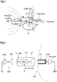
- Figure 1 shows an example configuration of a headphone HP worn by a user with several sound paths from an ambient sound source.
- the headphone HP shown in Figure 1 stands as an example for any noise cancellation enabled audio device and can particularly include in-ear headphones or earphones, on-ear headphones or over-ear headphones.
- the noise cancellation enabled audio device could also be a mobile phone or a similar device.
- the headphone HP in this example features a microphone FF_MIC, which is particularly designed as a feedforward noise cancellation microphone, and a loudspeaker LS. Internal processing details of the headphone HP are not shown here for reasons of a better overview.
- an ambient-to-ear sound path AE represents the sound path from an ambient sound source to a user's eardrum through the user's ear canal.
- a sound path from the ambient sound source to the microphone FF_MIC can be represented by the response function AM, also called ambient-to-mic response function AM.
- a response function or transfer function of the headphone HP in particular between the microphone FF_MIC and the loudspeaker LS, can be represented by a processor function P which may be parameterized as a noise cancellation filter during regular operation.
- the specification DE represents the acoustic path between the headphone's loudspeaker LS and the eardrum, and may be called a driver-to-ear response function.
- a further path, G can be taken into account from the headphone HP to the feedforward microphone FF_MIC which occurs through internal and/or external leakages in the headphone HP. This path G may represent a Driver to Feedforward Microphone FF MIC response and may also be called a leakage response or leakage path.
- one direct sound path namely the sound path AE and one combined sound path from the ambient sound source to the eardrum exist.
- the combined sound path results from the combination of sound path AM, processor path P, which incorporates the frequency responses of all the electrical elements of the noise cancellation electronics, and the driver-to-ear sound path DE.
- the combined sound paths may be written as AM.P.DE.
- FIG. 2 and an example flow diagram of a corresponding method as shown in Figure 3 .
- FIG. 2 shows an example implementation of a measurement configuration according to the improved measurement concept including an ambient sound source ASS comprising an ambient amplifier ADR and an ambient speaker ASP for playing a test signal TST.
- the noise cancellation enabled audio device HP comprises the microphone FF_MIC, whose signal is processed by a noise processor PROC and output via the loudspeaker LS.
- the noise processor PROC features a control interface CI, over which processing parameters of the noise processor PROC can be set, like filter parameters or gain factors a1, a2, a3 for respective proportional transfer functions.
- the audio device HP is placed onto a measurement fixture MF, which may be an artificial head with an ear canal representation EC, at the end of which a test microphone ECM is located for recording a measurement signal MES via a microphone amplifier MICAMP.
- a measurement fixture MF which may be an artificial head with an ear canal representation EC, at the end of which a test microphone ECM is located for recording a measurement signal MES via a microphone amplifier MICAMP.
- FIG. 3 an example block diagram showing a method flow of a method for determining a response function of a noise cancellation enabled audio device, in particular headphone, is shown.
- the method may be operated with the example measurement setup shown in Figure 2 .
- the audio device As shown in block 310, as a prerequisite the audio device is placed onto the measurement fixture MF, such that a loudspeaker LS of the audio device HP faces the ear canal representation EC of the measurement fixture MF.
- Block 320 includes the measuring of two or more response functions X, Y and, optionally, Z.
- Each of the response functions is measured between the ambient sound source ASS and the test microphone ECM located within the ear canal representation EC that preferably emulates the position of a user's eardrum.
- parameters of the noise processor PROC are set to a proportional transfer function with a specific gain factor.
- the first response function X is measured with the first gain factor chosen to a factor a1
- the second response function Y is measured with the second gain factor set to a factor a2
- the third, optional, response function Z is measured with the third gain factor set to a factor a3. All gain factors a1, a2 and a3 are chosen differently.
- Measurement of the response functions X, Y and Z for example is performed by playing an appropriate test signal TST from the ambient sound source ASS and recording an associated response signal MES with the test microphone ECM.
- the response functions X, Y and Z can then be determined from the test signal TST and the corresponding response signal MES.
- the measured response functions X, Y and Z represent a frequency response having phase and amplitude over a given frequency range.
- Such frequency responses may also be represented with a complex notation with real part and imaginary part, which is well-known in the field of signal processing.
- a model response function F is determined based on at least the first and the second response functions X, Y and the associated gain factors a1, a2. In some implementations, also the optional third response function Z and the corresponding third gain factor a3 may be used.
- the model response function F represents the ideal response of the noise processor PROC for an optimum noise cancellation performance based on the measurements performed before.
- a filter function for the processor PROC can be determined based on the model response function F.
- parameters of a filter function of the processor PROC can be determined, for example with various design tools for adapting the filter parameters to the model response function F as close as possible or technically feasible.
- the filter parameters determined this way can be used for normal operation of the audio device, e.g. if the audio device or headphone is used by a user.
- FIG. 4 an example frequency response of a model response function F is shown with its amplitude in the upper diagram and its phase in the lower diagram.
- the filter function preferably is designed such that the frequency response of the model response function F is matched as close as possible.
- a response function M at the test microphone's ECM position basically results in the ambient-to-ear response function AE and a combination of the response function AM, the processor transfer function P and the driver to ear response function DE.
- M AE + AM . P . DE
- AM.P.DE representing the aforementioned combination.
- two different measurements for a first response function X and a second response function Y are performed, wherein parameters of the noise processor PROC are set to a proportional transfer function with the first gain factor a1 for the first response function X and with the second gain factor a2 for the second response function Y.
- model response function F is determined when the headphone or other audio device is fully assembled and no access to internal test points or the like is necessary.
- the combined leakage response G.DE abbreviated as L
- noise processor PROC implements different but known and predefined filter transfer functions P for each measurement instead of only using the proportional transfer functions with respective gain factors a1, a2 and, optionally a3. After making measurements for the first, second and, optionally, third response functions X, Y and Z, one can compensate for the known response functions implemented by the noise processor PROC.
- different but known filters for the two or three measurements can be implemented, which can improve the signal-to-noise ratio of the measurements.
- the predefined filter transfer functions only differ by an overall gain factor applied.
- the model response function F for the noise processor PROC is determined based on the predefined transfer function R, the response functions X, Y, and optionally Z, and on the gain factors a1, a2 and, optionally, a3.
- the result of all the calculations yield an answer F/R instead of the desired answer F, which can be compensated for due to knowledge of the predefined transfer function R.
- Detailed implementation of the necessary equations can be readily derived by the skilled person from the description above for the implementation using gain factors a1, a2 and, optionally a3 only.
- model response function F as determined with each of the example implementations described above, can be used as a model to design appropriate filter parameters for the transfer function P of the noise processor PROC.
- respective filter parameters can be determined offline, having knowledge of the model response function F, and afterwards be transferred to the audio device or headphone HP via the control interface CI.
- a main beneficiary of the improved measurement concept is the acoustical engineer who designs the ANC headphone.
- the improved measurement concept allows the engineer to make more accurate measurements of a reference headphone design and in a more convenient way. It has a secondary application area on a headphone production line where it would allow measurements to be made that could be used to select the optimum ANC filter for each unit as it is produced.
Landscapes
- Physics & Mathematics (AREA)
- Engineering & Computer Science (AREA)
- Acoustics & Sound (AREA)
- Signal Processing (AREA)
- Multimedia (AREA)
- Soundproofing, Sound Blocking, And Sound Damping (AREA)
- Circuit For Audible Band Transducer (AREA)
- Noise Elimination (AREA)
- Headphones And Earphones (AREA)
Description
- The present disclosure relates to a method for determining a response function of a noise cancellation enabled audio device, e.g. headphone.
- Nowadays a significant number of headphones, including earphones, are equipped with noise cancellation techniques. For example, such noise cancellation techniques are referred to as active noise cancellation or ambient noise cancellation, both abbreviated with ANC. ANC generally makes use of recording ambient noise that is processed for generating an anti-noise signal, which is then combined with a useful audio signal to be played over a speaker of the headphone. ANC can also be employed in other audio devices like handsets or mobile phones.
- Various ANC approaches make use of feedback, FB, microphones, feedforward, FF, microphones or a combination of feedback and feedforward microphones.
- FF and FB ANC is achieved by tuning a filter based on given acoustics of a system.
- Several methods are known to measure the acoustical and electrical paths in a feedforward ambient noise cancellation headphone and to derive the ideal filter for an ambient noise cancellation system.
- One standard method for deriving the ideal shape of the filter was thoroughly described by
Kimura et al in US 5,138,664 . The method involves measuring the individual response functions AE, AM, DE as illustrated inFigure 1 using standard laboratory equipment, such as a spectrum analyser, then combining the responses to yield the ideal ANC filter shape. - Developments of Kimura's method are described in patent
GB 2445984 B - The disadvantage of prior art methods is that they require access to test-points and stimulus points inside the headphone to make the measurements. These are not usually accessible when the headphone is fully assembled. The electro-acoustical transfer functions can also change as components of the headphone are fitted. For example when enclosing a PCB, the acoustical pathways through the headphone change. Also when fitting batteries, the mass of a headphone shell changes, causing the resonant characteristics to change. Inter alia for these reasons, prior art methods are less accurate.
- Document
WO 2017/129951 A1 discloses an apparatus for testing earphones that employs a head and torso simulator, HATS, having an eardrum microphone. - Document
US 2013/0039507 A1 discloses an electronic device with ANC capability that includes a noise microphone and a force sensor. An adaptive filter of the device's ANC portion is adapted based on the force signals from the force sensor. This for example allows to detect how strong the electronic device is pressed to a user's ear and to adapt the ANC filter to the acoustical conditions of the device resulting from the applied force. The document e.g. proposes equations to determine an optimal ANC filter function from basic filter functions weighted with force dependent scaling functions. - An objective to be achieved is to provide an improved measurement concept for noise cancellation in an audio device like a headphone or handset that allows to improve noise reduction performance.
- This objective is achieved with the subject matter of the independent claim. Embodiments and developments of the improved measurement concept are defined in the dependent claims.
- The improved measurement concept is based on the insight of understanding of systematic errors embedded in prior art methods of characterizing headphone acoustics. It was appreciated that unless measurements were made on a final product, the measurements were flawed, which would lead to degraded performance. Hence, according to the improved measurement concept, the measurements can be made when the headphone or other ANC enabled audio device is fully assembled, without changing the physical design of the device to accommodate special test ports, resulting in elimination of systematic errors associated with assembly.
- One aspect of the improved measurement concept is to understand how different paths through the electrical system of the device can be modified in a way that allows the internal electro-acoustical transfer functions to be extracted.
- Using the improved measurement concept, all of the measurements can be performed by measuring the acoustical response from an ambient sound source, e.g. an ambient speaker, to a test microphone located within an ear canal representation of a measurement fixture, e.g. an ear-canal microphone, under different conditions. This makes the process very simple and less error prone. In contrast, conventional methods make three measurements requiring the apparatus to be configured in at least two different ways. For example, the test microphone is located at a position within the ear canal representation corresponding to the eardrum of a user. This point can also be called the drum reference point, DRP.
- A further benefit of the improved measurement concept is that since the measurements are made with the signals passing through the ANC processor, the resulting model transfer function automatically includes the response shapes or delays (such as input and output coupling, analog-to-digital conversion and digital-to-analog conversion) associated with the ANC processor.
- In summary, the proposed method simplifies the process of making accurate acoustic response measurements and avoids that a measurement error will corrupt the result. The consequence is that the acoustical noise reduction performance will increase for headphones or other ANC enabled audio devices developed using the method.
- The improved measurement concept is able to solve the measurement issues for two groups of people: First, the headphone designer in the acoustics lab will be able to create more accurate filters using this method. Second, an OEM could potentially use the method on the production line as part of the quality control process to select an ANC filter that is optimized for each accessory. This would help to compensate for slight variations in acoustic response during manufacture.
- According to the invention, an improved measurement concept comprises a method for determining a response function of a noise cancellation enabled audio device, in particular a headphone, comprising placing the audio device onto a measurement fixture, wherein a loudspeaker of the audio device faces an ear canal representation of the measurement fixture. A first response function between an ambient sound source and a test microphone located within the ear canal representation is measured while parameters of the noise processor of the audio device are set to a proportional transfer function with a first gain factor. Similarly, a second response function between the ambient sound source and the test microphone is measured while parameters of the noise processor are set to a proportional transfer function with a second gain factor being different from the first gain factor. A model response function for the noise processor is determined based on the first response function, the second response function and the first and the second gain factors.
- For example, the model response function is an ideal representation of a transfer function of a filter of the noise processor to achieve optimum noise cancellation performance. Hence the model response function can be the basis for trimming filter parameters of the noise processor to match the model response function as well as possible.
- Accordingly, in various embodiments the method further comprises determining parameters of a filter function of the noise processor based on the model response function.
- In some implementations, the method further comprises determining an ambient-to-ear response function based on the first and/or the second response function, and determining an overall processor response function based on the first response function, the second response function and the first and the second gain factor. The model response function is determined from the ambient-to-ear response function and the overall processor response function. In particular, the overall processor response function represents a combined transfer function from the ambient sound source to a microphone of the audio device and from the loudspeaker of the audio device to the test microphone.
- Expressed as a formula, with AE being the ambient-to-ear response function and AM.DE being the overall processor response function, the model response function F can be expressed as

- Accordingly, the model response function F may be determined according to the formula

In some implementations a third response function is measured between the ambient sound source and the test microphone while parameters of the noise processor are set to a proportional transfer function with a third gain factor being different from both the first gain factor and the second gain factor. In such an implementation the model response function is determined based on the first, the second and the third response function, and on the first, the second and the third gain factor. - For example, in such implementations with three measurements, an ambient-to-ear response function is determined based on the first response function or on the first, the second and the third response function. An overall processor response function is determined based on the first, the second and the third response function and on the first, the second and the third gain factor. Similar to the implementation with two response function measurements, the model response function is determined from the ambient-to-ear response function and the overall processor response function. For example, equation (1) can also be applied in this case.
- For example, in the three measurements case, the model response function F can be determined according to the formula

- In some configurations of audio devices worn by a user, leakage between the loudspeaker of the audio device and the feedforward ANC microphone of the audio device may occur. The acoustical leakage pathway may be through the internal vents in the structure of the audio device or through a leakage in the seal between the audio device and the user. The acoustical pathway may be negligible. However, in some implementations with three response function measurements, a leakage response function is determined based on the first, the second and the third response function and on the first, the second and the third gain factor. Then, the overall processor response function is determined further based on the leakage response function.
- For example, the leakage response function represents a combined transfer function between output and input of the ANC-enabled audio device and the transfer function between the audio device's loudspeaker and the test microphone, respectively the user's eardrum, also called a driver-to-ear response function.
- With the three measured response functions and three unknown response functions, namely the ambient ear response function, the overall processor response function and the leakage response function, an equation system can be formed representing the various acoustic paths. The solution to this equation system allows to find the model response function according to equation (1).
- In the two or three measurement configurations with the noise processor being set to a proportional transfer function, a more or less frequency-independent transfer function for the noise processor is set having the respective defined gain factor. The frequency independence is at least given in a frequency range of interest.
- In various implementations, the first gain factor equals 0. Hence, with the first gain factor being 0, no signal is output by the loudspeaker of the audio device during the measurement. For example, the noise processor is disabled and/or muted during the measurement of the first response function to achieve the zero gain factor.
- Setting the first gain factor to zero may ease the determination of the model response function, because the measured first response function directly corresponds to the ambient-to-ear response function in this case.
- It has been further found that there is a more general set of measurements that allow the model response function to be evaluated. In particular, the more general solution is that the noise processor implements different but known and predefined filter transfer functions for each measurement instead of only using the proportional transfer functions with respective gain factors. After making measurement for the first, second and, optionally, third response functions, one can compensate for the known response functions implemented by the noise processor.
- One scenario where this might be useful is to configure the noise processor with an ANC filter for all measurements. The improved method will then yield an "error" function that must be added to the implemented ANC filter that will yield better ANC. This could be useful when implementing an analog ANC solution which had more than one filter stages. In this scenario the method could be run once for each filter stage, and provide a successively improved ANC filter.
- A second scenario is where you choose to implement different but known filters for the two or three measurements. The reason for implementing the filters might be to improve the signal-to-noise ratio of the measurements. One would have to correct for these known filter shapes after calculating the individual first, second and, optionally, third response functions. Preferably, the predefined filter transfer functions only differ by an overall gain factor applied.
- Accordingly, in a further embodiment according to the improved measurement concept, a method for determining a model response function of a noise cancellation enabled audio device, in particular a headphone, comprises placing the audio device onto a measurement fixture, wherein a loudspeaker of the audio device faces an ear canal representation of the measurement fixture. A first response function between an ambient sound source and a test microphone located within the ear canal representation is measured while parameters of the noise processor of the audio device are set to a predefined transfer function in combination with a first gain factor. Similarly, a second response function between the ambient sound source and the test microphone is measured while parameters of the noise processor are set to the predefined transfer function in combination with a second gain factor being different from the first gain factor. A model response function for the noise processor is determined based on the predefined transfer function, the first response function, the second response function and the first and the second gain factor.
- In some of such implementations a third response function is measured between the ambient sound source and the test microphone while parameters of the noise processor are set to the predefined transfer function in combination with a third gain factor being different from both the first gain factor and the second gain factor. In such an implementation the model response function is determined based on the predefined transfer function, the first, the second and the third response function, and on the first, the second and the third gain factor.
- Measuring the various response functions may be accomplished by playing a test signal from the ambient sound source, recording a response signal with the test microphone in response to the played test signal and determining, e.g. calculating, the response function from the test signal and the response signal. The test signal may be a combination of various discrete frequency signals or a specific noise test pattern or the like. The measured response functions may be determined using a spectrum analyzer, for example.
- In all the implementations described above, preferably each of the response functions measured between the ambient sound source and the test microphone is measured without accessing any test point within the audio device. Similarly, preferably each of the response functions measured between the ambient sound source and the test microphone is measured without the audio device being disassembled during the respective measurements.
- For example, the audio device and the noise processor are enabled for feedforward noise cancellation.
- The improved measurement concept will be described in more detail in the following with the aid of drawings. Elements having the same or similar function bear the same reference numerals throughout the drawings. Hence their description is not necessarily repeated in following drawings.
- In the drawings:
- Figure 1
- shows an example headphone worn by a user with several sound paths from an ambient sound source;
- Figure 2
- shows an example implementation of a measurement configuration according to the improved measurement concept;
- Figure 3
- shows an example implementation of a method according to the improved measurement concept; and
- Figure 4
- shows an example frequency response of a model response function.
-
Figure 1 shows an example configuration of a headphone HP worn by a user with several sound paths from an ambient sound source. The headphone HP shown inFigure 1 stands as an example for any noise cancellation enabled audio device and can particularly include in-ear headphones or earphones, on-ear headphones or over-ear headphones. Instead of a headphone, the noise cancellation enabled audio device could also be a mobile phone or a similar device. - The headphone HP in this example features a microphone FF_MIC, which is particularly designed as a feedforward noise cancellation microphone, and a loudspeaker LS. Internal processing details of the headphone HP are not shown here for reasons of a better overview.
- In the configuration shown in
Figure 1 , several sound paths exist, of which each can be represented by a respective response function or transfer function. For example, an ambient-to-ear sound path AE represents the sound path from an ambient sound source to a user's eardrum through the user's ear canal. A sound path from the ambient sound source to the microphone FF_MIC can be represented by the response function AM, also called ambient-to-mic response function AM. - A response function or transfer function of the headphone HP, in particular between the microphone FF_MIC and the loudspeaker LS, can be represented by a processor function P which may be parameterized as a noise cancellation filter during regular operation. The specification DE represents the acoustic path between the headphone's loudspeaker LS and the eardrum, and may be called a driver-to-ear response function. A further path, G, can be taken into account from the headphone HP to the feedforward microphone FF_MIC which occurs through internal and/or external leakages in the headphone HP. This path G may represent a Driver to Feedforward Microphone FF MIC response and may also be called a leakage response or leakage path.
- Accordingly, during operation, one direct sound path, namely the sound path AE and one combined sound path from the ambient sound source to the eardrum exist. The combined sound path results from the combination of sound path AM, processor path P, which incorporates the frequency responses of all the electrical elements of the noise cancellation electronics, and the driver-to-ear sound path DE. The combined sound paths may be written as AM.P.DE.
- For optimum noise cancellation performance, the processor noise path P may be parameterized to represent more or less the model response function F as defined in equation (1), such that

- The determination of the model response function F will be explained in more detail in conjunction with an example implementation of a measurement configuration as shown in
-
Figure 2 , and an example flow diagram of a corresponding method as shown inFigure 3 . -
Figure 2 shows an example implementation of a measurement configuration according to the improved measurement concept including an ambient sound source ASS comprising an ambient amplifier ADR and an ambient speaker ASP for playing a test signal TST. The noise cancellation enabled audio device HP comprises the microphone FF_MIC, whose signal is processed by a noise processor PROC and output via the loudspeaker LS. The noise processor PROC features a control interface CI, over which processing parameters of the noise processor PROC can be set, like filter parameters or gain factors a1, a2, a3 for respective proportional transfer functions. The audio device HP is placed onto a measurement fixture MF, which may be an artificial head with an ear canal representation EC, at the end of which a test microphone ECM is located for recording a measurement signal MES via a microphone amplifier MICAMP. It should be noted that at least the measurement fixture MF and the ambient sound source ASS are represented with their basic functions, namely playing a test signal TST and recording a measurement signal MES without excluding more sophisticated implementations. - Referring now to
Figure 3 , an example block diagram showing a method flow of a method for determining a response function of a noise cancellation enabled audio device, in particular headphone, is shown. The method may be operated with the example measurement setup shown inFigure 2 . - As shown in
block 310, as a prerequisite the audio device is placed onto the measurement fixture MF, such that a loudspeaker LS of the audio device HP faces the ear canal representation EC of the measurement fixture MF. -
Block 320 includes the measuring of two or more response functions X, Y and, optionally, Z. Each of the response functions is measured between the ambient sound source ASS and the test microphone ECM located within the ear canal representation EC that preferably emulates the position of a user's eardrum. - According to the improved measurement concept, for each of the response functions to be measured parameters of the noise processor PROC are set to a proportional transfer function with a specific gain factor. For example, the first response function X is measured with the first gain factor chosen to a factor a1, the second response function Y is measured with the second gain factor set to a factor a2, and the third, optional, response function Z is measured with the third gain factor set to a factor a3. All gain factors a1, a2 and a3 are chosen differently.
- Measurement of the response functions X, Y and Z for example is performed by playing an appropriate test signal TST from the ambient sound source ASS and recording an associated response signal MES with the test microphone ECM. The response functions X, Y and Z can then be determined from the test signal TST and the corresponding response signal MES. For example, the measured response functions X, Y and Z represent a frequency response having phase and amplitude over a given frequency range. Such frequency responses may also be represented with a complex notation with real part and imaginary part, which is well-known in the field of signal processing.
- Referring now to block 330 of
Figure 3 , a model response function F is determined based on at least the first and the second response functions X, Y and the associated gain factors a1, a2. In some implementations, also the optional third response function Z and the corresponding third gain factor a3 may be used. - The model response function F represents the ideal response of the noise processor PROC for an optimum noise cancellation performance based on the measurements performed before.
- Hence, in
optional block 340, a filter function for the processor PROC can be determined based on the model response function F. In particular, parameters of a filter function of the processor PROC can be determined, for example with various design tools for adapting the filter parameters to the model response function F as close as possible or technically feasible. - Finally, the filter parameters determined this way can be used for normal operation of the audio device, e.g. if the audio device or headphone is used by a user.
- Referring to
Figure 4 , an example frequency response of a model response function F is shown with its amplitude in the upper diagram and its phase in the lower diagram. - The filter function preferably is designed such that the frequency response of the model response function F is matched as close as possible.
- Referring back to
Figure 3 , in the following various implementations of the method for determining the model response function will be explained in more detail. - For example, if the influence of the leakage path G is neglected, a response function M at the test microphone's ECM position basically results in the ambient-to-ear response function AE and a combination of the response function AM, the processor transfer function P and the driver to ear response function DE. This can hence be represented by

- In some implementations, two different measurements for a first response function X and a second response function Y are performed, wherein parameters of the noise processor PROC are set to a proportional transfer function with the first gain factor a1 for the first response function X and with the second gain factor a2 for the second response function Y. With equation (5), the first response function X can be written as


- Taking equations (6) and (7), the following equation can be derived


- Starting, for example, from equation (6), the ambient-to-ear response function AE can be derived as

- Inserting the expressions of equations (9) and (10) into equation (1), the model response function F can be written as

- In summary, the model response function F is determined when the headphone or other audio device is fully assembled and no access to internal test points or the like is necessary.
- Equation (11) can be simplified, for example by choosing the first gain factor a1 to be zero, such that no signals are transferred from the audio device's microphone FF_MIC to its loudspeaker LS. Besides actually setting filter parameters of the processor transfer function P to achieve the zero gain factor, this can also be achieved by disabling and/or muting the noise processor PROC during measurement of the first response function X. In such a configuration, the model response function F simplifies to

- In some implementations also a third measurement can be performed, i.e. a third response function Z can be measured with a third gain factor a3 for the proportional transfer function of the noise processor PROC. Taking into account equation (5) again, this results in

- Similar to equation (9) above, the combined response AM.DE can now be determined from equations (7) and (13), resulting in

- In analogy to equation (10), the ambient-to-ear response function AE can be determined as

- Using equation (1), the model response function F for example results in

- If the first gain factor a1 is chosen to be zero, as described above, equation (16) simplifies to

- Moreover, if for example the second and the third gain factor a2, a3 are chosen to a2 = +1 and a3 = -1, equation (17) further simplifies to

- While in the previous example implementations the leakage response G has been neglected, it can be considered in implementations as described in the following. For example, performing the measurement of the three response functions X, Y, Z as described above, these can be represented as


- With the three measurements, it is possible to determine the three unknowns AE, AM.DE and G.DE for finally finding a representation of the model response function F according to equation (1).
- Taking an example implementation for such a configuration with the three gain factors a1, a2 and a3 chosen to be a1 = 0, a2 = +1 and a3 = -1, equations (19), (20) and (21) simplify to


- With these simplifications, the combined leakage response G.DE, abbreviated as L, can be expressed as

- The combined response function AM.DE can then be expressed as

- Finally, using equations (22), (26) and (25), equation (1) can be rewritten as

- In alternative implementations, it is also possible to use an approach where the noise processor PROC implements different but known and predefined filter transfer functions P for each measurement instead of only using the proportional transfer functions with respective gain factors a1, a2 and, optionally a3. After making measurements for the first, second and, optionally, third response functions X, Y and Z, one can compensate for the known response functions implemented by the noise processor PROC.
- For example, different but known filters for the two or three measurements can be implemented, which can improve the signal-to-noise ratio of the measurements. One would have to correct for these known filter shapes after calculating the individual first, second and, optionally, third response functions X, Y and Z. Preferably, the predefined filter transfer functions only differ by an overall gain factor applied.
- Accordingly, in such implementations, the filter transfer function P of the noise processor PROC may be set to a predefined transfer function R in combination with the respective gain factors a1, a2 and, optionally a3, such that two or three known filter functions result. This is similarly accomplished using the control interface CI. Based on equation (5), this results in equations similar to equations (6), (7) and (13), namely:


- The model response function F for the noise processor PROC is determined based on the predefined transfer function R, the response functions X, Y, and optionally Z, and on the gain factors a1, a2 and, optionally, a3.
- For example, the result of all the calculations yield an answer F/R instead of the desired answer F, which can be compensated for due to knowledge of the predefined transfer function R. Detailed implementation of the necessary equations can be readily derived by the skilled person from the description above for the implementation using gain factors a1, a2 and, optionally a3 only.
- As mentioned before, the model response function F as determined with each of the example implementations described above, can be used as a model to design appropriate filter parameters for the transfer function P of the noise processor PROC. For example, respective filter parameters can be determined offline, having knowledge of the model response function F, and afterwards be transferred to the audio device or headphone HP via the control interface CI.
- For example, a main beneficiary of the improved measurement concept is the acoustical engineer who designs the ANC headphone. The improved measurement concept allows the engineer to make more accurate measurements of a reference headphone design and in a more convenient way. It has a secondary application area on a headphone production line where it would allow measurements to be made that could be used to select the optimum ANC filter for each unit as it is produced.
-
- HP
- audio device
- FF_MIC
- microphone
- LS
- loudspeaker
- AM
- ambient-to-microphone response function
- AE
- ambient-to-ear response function
- DE
- driver-to-ear response function
- G
- leakage response function
- P
- processor transfer function
- F
- model response function
- PROC
- noise processor
- CI
- control interface
- ASS
- ambient sound source
- ADR
- ambient driver
- ASP
- ambient speaker
- EC
- ear canal representation
- ECM
- test microphone
- MICAMP
- microphone amplifier
- TST
- test signal
- MES
- measurement signal
- MF
- measurement fixture
Claims (14)
- A method for determining a response function of a noise cancellation enabled audio device (HP), in particular headphone, the method comprising- placing the audio device (HP) onto a measurement fixture (MF), wherein a loudspeaker (LS) of the audio device (HP) faces an ear canal representation (EC) of the measurement fixture (MF);- measuring a first response function between an ambient sound source (ASS) and a test microphone (ECM) located within the ear canal representation (EC) while parameters of a noise processor (PROC) of the audio device (HP) are set to a predefined transfer function in combination with a first gain factor (a1);- measuring a second response function between the ambient sound source (ASS) and the test microphone (ECM) while parameters of the noise processor (PROC) are set to the predefined transfer function in combination with a second gain factor (a2) being different from the first gain factor (a1);- determining a model response function (F) for the noise processor (PROC) based on the predefined transfer function, the first response function, the second response function and the first and the second gain factor (a1, a2) .
- The method according to claim 1, wherein the predefined transfer function is a proportional transfer function.
- The method according to claim 1 or 2, further comprising- determining an ambient-to-ear response function (AE) based on the first and/or the second response function; and- determining an overall processor response function (AM.DE) based on the first response function, the second response function and the first and the second gain factor (a1, a2); wherein- the model response function (F) is determined from the ambient-to-ear response function (AE) and the overall processor response function (AM.DE).
- The method according to one of claims 1 to 3, wherein the model response function F is determined according to the formula

- The method according to claim 1 or 2, further comprising- measuring a third response function between the ambient sound source (ASS) and the test microphone (ECM) while parameters of the noise processor (PROC) are set to the predefined transfer function in combination with a third gain factor (a3) being different from the first gain factor (a1) and the second gain factor (a2); wherein- the model response function (F) is determined based on the predefined transfer function, the first, the second and the third response function, and the first, the second and the third gain factor (a1, a2, a3).
- The method according to claim 5, further comprising- determining an ambient-to-ear response function (AE) based on the first response function or on the first, the second and the third response function; and- determining an overall processor response function (AM.DE) based on the first, the second and the third response function and on the first, the second and the third gain factor (a1, a2, a3); wherein- the model response function (F) is determined from the ambient-to-ear response function (AE) and the overall processor response function (AM.DE).
- The method according to claim 5 or 6, wherein the model response function F is determined according to the formula

- The method according to claim 6, further comprising- determining a leakage response function (G.DE) based on the first, the second and the third response function and on the first, the second and the third gain factor (a1, a2, a3); wherein- the overall processor response function (AM.DE) is determined further based on the leakage response function (G. DE).
- The method according to one of claims 1 to 8, wherein the first gain factor (a1) equals zero.
- The method according to claim 9, wherein the noise processor (PROC) is disabled and/or muted during measurement of first response function.
- The method according to one of claims 1 to 10, wherein each of the response functions measured between the ambient sound source (ASS) and the test microphone (ECM) is measured without accessing any test point within the audio device (HP) .
- The method according to one of claims 1 to 11, wherein each of the response functions measured between the ambient sound source (ASS) and the test microphone (ECM) is measured without the audio device (HP) being disassembled during the respective measurements.
- The method according to one of claims 1 to 12, wherein the audio device (HP) and the noise processor (PROC) are enabled for feedforward noise cancellation.
- The method according to one of claims 1 to 13, further comprising determining parameters of a filter function of the noise processor (PROC) based on the model response function (F) .
Priority Applications (5)
| Application Number | Priority Date | Filing Date | Title |
|---|---|---|---|
| EP17199694.5A EP3480809B1 (en) | 2017-11-02 | 2017-11-02 | Method for determining a response function of a noise cancellation enabled audio device |
| TW107135401A TWI796369B (en) | 2017-11-02 | 2018-10-08 | Method for determining a response function of a noise cancellation enabled audio device |
| PCT/EP2018/079027 WO2019086298A1 (en) | 2017-11-02 | 2018-10-23 | Method for determining a response function of a noise cancellation enabled audio device |
| US16/759,638 US11044557B2 (en) | 2017-11-02 | 2018-10-23 | Method for determining a response function of a noise cancellation enabled audio device |
| CN201880071272.7A CN111656435A (en) | 2017-11-02 | 2018-10-23 | Method for determining response function of audio device enabling noise cancellation |
Applications Claiming Priority (1)
| Application Number | Priority Date | Filing Date | Title |
|---|---|---|---|
| EP17199694.5A EP3480809B1 (en) | 2017-11-02 | 2017-11-02 | Method for determining a response function of a noise cancellation enabled audio device |
Publications (2)
| Publication Number | Publication Date |
|---|---|
| EP3480809A1 EP3480809A1 (en) | 2019-05-08 |
| EP3480809B1 true EP3480809B1 (en) | 2021-10-13 |
Family
ID=60201944
Family Applications (1)
| Application Number | Title | Priority Date | Filing Date |
|---|---|---|---|
| EP17199694.5A Active EP3480809B1 (en) | 2017-11-02 | 2017-11-02 | Method for determining a response function of a noise cancellation enabled audio device |
Country Status (5)
| Country | Link |
|---|---|
| US (1) | US11044557B2 (en) |
| EP (1) | EP3480809B1 (en) |
| CN (1) | CN111656435A (en) |
| TW (1) | TWI796369B (en) |
| WO (1) | WO2019086298A1 (en) |
Families Citing this family (4)
| Publication number | Priority date | Publication date | Assignee | Title |
|---|---|---|---|---|
| US10867594B1 (en) * | 2019-10-02 | 2020-12-15 | xMEMS Labs, Inc. | Audio apparatus and audio method thereof |
| CN111050264A (en) * | 2019-11-13 | 2020-04-21 | 歌尔股份有限公司 | Noise test system and test method for simulating single-ended microphone |
| CN113038318B (en) * | 2019-12-25 | 2022-06-07 | 荣耀终端有限公司 | Voice signal processing method and device |
| US11468875B2 (en) | 2020-12-15 | 2022-10-11 | Google Llc | Ambient detector for dual mode ANC |
Family Cites Families (17)
| Publication number | Priority date | Publication date | Assignee | Title |
|---|---|---|---|---|
| US5138644A (en) | 1988-08-26 | 1992-08-11 | Glitsch Field Services/Nde, Inc. | Method and apparatus for measuring the wall thickness of insulated pipe |
| US5138664A (en) | 1989-03-25 | 1992-08-11 | Sony Corporation | Noise reducing device |
| US6594365B1 (en) * | 1998-11-18 | 2003-07-15 | Tenneco Automotive Operating Company Inc. | Acoustic system identification using acoustic masking |
| GB2361395B (en) * | 2000-04-15 | 2005-01-05 | Central Research Lab Ltd | A method of audio signal processing for a loudspeaker located close to an ear |
| KR100584609B1 (en) * | 2004-11-02 | 2006-05-30 | 삼성전자주식회사 | Method and apparatus for compensating the frequency characteristic of earphone |
| GB2434708B (en) * | 2006-01-26 | 2008-02-27 | Sonaptic Ltd | Ambient noise reduction arrangements |
| GB2445984B (en) | 2007-01-25 | 2011-12-07 | Sonaptic Ltd | Ambient noise reduction |
| JP4599444B2 (en) * | 2008-12-09 | 2010-12-15 | 株式会社東芝 | Acoustic device and method for controlling acoustic device |
| US8654990B2 (en) * | 2009-02-09 | 2014-02-18 | Waves Audio Ltd. | Multiple microphone based directional sound filter |
| US9495952B2 (en) * | 2011-08-08 | 2016-11-15 | Qualcomm Incorporated | Electronic devices for controlling noise |
| US20150172807A1 (en) * | 2013-12-13 | 2015-06-18 | Gn Netcom A/S | Apparatus And A Method For Audio Signal Processing |
| WO2016029461A1 (en) * | 2014-08-29 | 2016-03-03 | 安百特半导体有限公司 | Feedforward-and-feedback-combined noise cancellation earphone and drive circuit thereof |
| US9706288B2 (en) * | 2015-03-12 | 2017-07-11 | Apple Inc. | Apparatus and method of active noise cancellation in a personal listening device |
| US20160300562A1 (en) * | 2015-04-08 | 2016-10-13 | Apple Inc. | Adaptive feedback control for earbuds, headphones, and handsets |
| KR20180044324A (en) * | 2015-08-20 | 2018-05-02 | 시러스 로직 인터내셔널 세미컨덕터 리미티드 | A feedback adaptive noise cancellation (ANC) controller and a method having a feedback response partially provided by a fixed response filter |
| GB201601453D0 (en) * | 2016-01-26 | 2016-03-09 | Soundchip Sa | Method and apparatus for testing earphone apparatus |
| US10834494B1 (en) * | 2019-12-13 | 2020-11-10 | Bestechnic (Shanghai) Co., Ltd. | Active noise control headphones |
-
2017
- 2017-11-02 EP EP17199694.5A patent/EP3480809B1/en active Active
-
2018
- 2018-10-08 TW TW107135401A patent/TWI796369B/en active
- 2018-10-23 CN CN201880071272.7A patent/CN111656435A/en active Pending
- 2018-10-23 US US16/759,638 patent/US11044557B2/en active Active
- 2018-10-23 WO PCT/EP2018/079027 patent/WO2019086298A1/en active Application Filing
Also Published As
| Publication number | Publication date |
|---|---|
| CN111656435A (en) | 2020-09-11 |
| US20200288244A1 (en) | 2020-09-10 |
| TWI796369B (en) | 2023-03-21 |
| US11044557B2 (en) | 2021-06-22 |
| WO2019086298A1 (en) | 2019-05-09 |
| EP3480809A1 (en) | 2019-05-08 |
| TW201919037A (en) | 2019-05-16 |
Similar Documents
| Publication | Publication Date | Title |
|---|---|---|
| US11044557B2 (en) | Method for determining a response function of a noise cancellation enabled audio device | |
| US8306250B2 (en) | Sound reproducing apparatus using in-ear earphone | |
| EP2202998B1 (en) | A device for and a method of processing audio data | |
| KR101285857B1 (en) | Ambient noise reduction arrangements | |
| Denk et al. | An individualised acoustically transparent earpiece for hearing devices | |
| US11600256B2 (en) | Managing characteristics of active noise reduction | |
| US20100105447A1 (en) | Ambient noise reduction | |
| EP3871212B1 (en) | Tuning method, manufacturing method, computer-readable storage medium and tuning system | |
| CN105491495B (en) | Deterministic sequence based feedback estimation | |
| US10984779B2 (en) | Audio adjustment method and associated audio adjustment device for active noise cancellation | |
| CN113450754A (en) | Active noise cancellation system and method | |
| Jin et al. | Individualized Hear-through for Acoustic Transparency using PCA-based sound pressure estimation at the eardrum | |
| CN111862924A (en) | Audio adjusting method for active noise reduction and related audio adjusting device | |
| Bouse | Headphone measurement tool implemented in Matlab | |
| CN109716792B (en) | Amplitude and phase correction for hearing devices | |
| Welti | Improved measurement of leakage effects for circum-aural and supra-aural headphones | |
| US20230154449A1 (en) | Method, device, headphones and computer program for actively suppressing interfering noise | |
| US20230109140A1 (en) | Method for determining a head related transfer function and hearing device | |
| CN115460526B (en) | Method for determining hearing model, electronic equipment and system | |
| Nishimura et al. | An attempt to calibrate headphones for reproduction of sound pressure at the eardrum | |
| CN117896663A (en) | Method for determining transfer function of feedforward filter, related device and test system | |
| CN113053347A (en) | Target frequency response detection method and system for noise reduction earphone feedforward filter |
Legal Events
| Date | Code | Title | Description |
|---|---|---|---|
| PUAI | Public reference made under article 153(3) epc to a published international application that has entered the european phase |
Free format text: ORIGINAL CODE: 0009012 |
|
| STAA | Information on the status of an ep patent application or granted ep patent |
Free format text: STATUS: THE APPLICATION HAS BEEN PUBLISHED |
|
| AK | Designated contracting states |
Kind code of ref document: A1 Designated state(s): AL AT BE BG CH CY CZ DE DK EE ES FI FR GB GR HR HU IE IS IT LI LT LU LV MC MK MT NL NO PL PT RO RS SE SI SK SM TR |
|
| AX | Request for extension of the european patent |
Extension state: BA ME |
|
| STAA | Information on the status of an ep patent application or granted ep patent |
Free format text: STATUS: REQUEST FOR EXAMINATION WAS MADE |
|
| 17P | Request for examination filed |
Effective date: 20190910 |
|
| RBV | Designated contracting states (corrected) |
Designated state(s): AL AT BE BG CH CY CZ DE DK EE ES FI FR GB GR HR HU IE IS IT LI LT LU LV MC MK MT NL NO PL PT RO RS SE SI SK SM TR |
|
| GRAP | Despatch of communication of intention to grant a patent |
Free format text: ORIGINAL CODE: EPIDOSNIGR1 |
|
| STAA | Information on the status of an ep patent application or granted ep patent |
Free format text: STATUS: GRANT OF PATENT IS INTENDED |
|
| INTG | Intention to grant announced |
Effective date: 20210727 |
|
| GRAS | Grant fee paid |
Free format text: ORIGINAL CODE: EPIDOSNIGR3 |
|
| GRAA | (expected) grant |
Free format text: ORIGINAL CODE: 0009210 |
|
| STAA | Information on the status of an ep patent application or granted ep patent |
Free format text: STATUS: THE PATENT HAS BEEN GRANTED |
|
| AK | Designated contracting states |
Kind code of ref document: B1 Designated state(s): AL AT BE BG CH CY CZ DE DK EE ES FI FR GB GR HR HU IE IS IT LI LT LU LV MC MK MT NL NO PL PT RO RS SE SI SK SM TR |
|
| REG | Reference to a national code |
Ref country code: GB Ref legal event code: FG4D |
|
| REG | Reference to a national code |
Ref country code: CH Ref legal event code: EP |
|
| REG | Reference to a national code |
Ref country code: DE Ref legal event code: R096 Ref document number: 602017047477 Country of ref document: DE |
|
| REG | Reference to a national code |
Ref country code: IE Ref legal event code: FG4D |
|
| REG | Reference to a national code |
Ref country code: AT Ref legal event code: REF Ref document number: 1438767 Country of ref document: AT Kind code of ref document: T Effective date: 20211115 |
|
| REG | Reference to a national code |
Ref country code: LT Ref legal event code: MG9D |
|
| REG | Reference to a national code |
Ref country code: NL Ref legal event code: MP Effective date: 20211013 |
|
| REG | Reference to a national code |
Ref country code: AT Ref legal event code: MK05 Ref document number: 1438767 Country of ref document: AT Kind code of ref document: T Effective date: 20211013 |
|
| PG25 | Lapsed in a contracting state [announced via postgrant information from national office to epo] |
Ref country code: RS Free format text: LAPSE BECAUSE OF FAILURE TO SUBMIT A TRANSLATION OF THE DESCRIPTION OR TO PAY THE FEE WITHIN THE PRESCRIBED TIME-LIMIT Effective date: 20211013 Ref country code: LT Free format text: LAPSE BECAUSE OF FAILURE TO SUBMIT A TRANSLATION OF THE DESCRIPTION OR TO PAY THE FEE WITHIN THE PRESCRIBED TIME-LIMIT Effective date: 20211013 Ref country code: FI Free format text: LAPSE BECAUSE OF FAILURE TO SUBMIT A TRANSLATION OF THE DESCRIPTION OR TO PAY THE FEE WITHIN THE PRESCRIBED TIME-LIMIT Effective date: 20211013 Ref country code: BG Free format text: LAPSE BECAUSE OF FAILURE TO SUBMIT A TRANSLATION OF THE DESCRIPTION OR TO PAY THE FEE WITHIN THE PRESCRIBED TIME-LIMIT Effective date: 20220113 Ref country code: AT Free format text: LAPSE BECAUSE OF FAILURE TO SUBMIT A TRANSLATION OF THE DESCRIPTION OR TO PAY THE FEE WITHIN THE PRESCRIBED TIME-LIMIT Effective date: 20211013 |
|
| PG25 | Lapsed in a contracting state [announced via postgrant information from national office to epo] |
Ref country code: IS Free format text: LAPSE BECAUSE OF FAILURE TO SUBMIT A TRANSLATION OF THE DESCRIPTION OR TO PAY THE FEE WITHIN THE PRESCRIBED TIME-LIMIT Effective date: 20220213 Ref country code: SE Free format text: LAPSE BECAUSE OF FAILURE TO SUBMIT A TRANSLATION OF THE DESCRIPTION OR TO PAY THE FEE WITHIN THE PRESCRIBED TIME-LIMIT Effective date: 20211013 Ref country code: PT Free format text: LAPSE BECAUSE OF FAILURE TO SUBMIT A TRANSLATION OF THE DESCRIPTION OR TO PAY THE FEE WITHIN THE PRESCRIBED TIME-LIMIT Effective date: 20220214 Ref country code: PL Free format text: LAPSE BECAUSE OF FAILURE TO SUBMIT A TRANSLATION OF THE DESCRIPTION OR TO PAY THE FEE WITHIN THE PRESCRIBED TIME-LIMIT Effective date: 20211013 Ref country code: NO Free format text: LAPSE BECAUSE OF FAILURE TO SUBMIT A TRANSLATION OF THE DESCRIPTION OR TO PAY THE FEE WITHIN THE PRESCRIBED TIME-LIMIT Effective date: 20220113 Ref country code: NL Free format text: LAPSE BECAUSE OF FAILURE TO SUBMIT A TRANSLATION OF THE DESCRIPTION OR TO PAY THE FEE WITHIN THE PRESCRIBED TIME-LIMIT Effective date: 20211013 Ref country code: LV Free format text: LAPSE BECAUSE OF FAILURE TO SUBMIT A TRANSLATION OF THE DESCRIPTION OR TO PAY THE FEE WITHIN THE PRESCRIBED TIME-LIMIT Effective date: 20211013 Ref country code: HR Free format text: LAPSE BECAUSE OF FAILURE TO SUBMIT A TRANSLATION OF THE DESCRIPTION OR TO PAY THE FEE WITHIN THE PRESCRIBED TIME-LIMIT Effective date: 20211013 Ref country code: GR Free format text: LAPSE BECAUSE OF FAILURE TO SUBMIT A TRANSLATION OF THE DESCRIPTION OR TO PAY THE FEE WITHIN THE PRESCRIBED TIME-LIMIT Effective date: 20220114 Ref country code: ES Free format text: LAPSE BECAUSE OF FAILURE TO SUBMIT A TRANSLATION OF THE DESCRIPTION OR TO PAY THE FEE WITHIN THE PRESCRIBED TIME-LIMIT Effective date: 20211013 |
|
| REG | Reference to a national code |
Ref country code: CH Ref legal event code: PL |
|
| REG | Reference to a national code |
Ref country code: DE Ref legal event code: R097 Ref document number: 602017047477 Country of ref document: DE |
|
| PG25 | Lapsed in a contracting state [announced via postgrant information from national office to epo] |
Ref country code: SM Free format text: LAPSE BECAUSE OF FAILURE TO SUBMIT A TRANSLATION OF THE DESCRIPTION OR TO PAY THE FEE WITHIN THE PRESCRIBED TIME-LIMIT Effective date: 20211013 Ref country code: SK Free format text: LAPSE BECAUSE OF FAILURE TO SUBMIT A TRANSLATION OF THE DESCRIPTION OR TO PAY THE FEE WITHIN THE PRESCRIBED TIME-LIMIT Effective date: 20211013 Ref country code: RO Free format text: LAPSE BECAUSE OF FAILURE TO SUBMIT A TRANSLATION OF THE DESCRIPTION OR TO PAY THE FEE WITHIN THE PRESCRIBED TIME-LIMIT Effective date: 20211013 Ref country code: MC Free format text: LAPSE BECAUSE OF FAILURE TO SUBMIT A TRANSLATION OF THE DESCRIPTION OR TO PAY THE FEE WITHIN THE PRESCRIBED TIME-LIMIT Effective date: 20211013 Ref country code: LU Free format text: LAPSE BECAUSE OF NON-PAYMENT OF DUE FEES Effective date: 20211102 Ref country code: EE Free format text: LAPSE BECAUSE OF FAILURE TO SUBMIT A TRANSLATION OF THE DESCRIPTION OR TO PAY THE FEE WITHIN THE PRESCRIBED TIME-LIMIT Effective date: 20211013 Ref country code: DK Free format text: LAPSE BECAUSE OF FAILURE TO SUBMIT A TRANSLATION OF THE DESCRIPTION OR TO PAY THE FEE WITHIN THE PRESCRIBED TIME-LIMIT Effective date: 20211013 Ref country code: CZ Free format text: LAPSE BECAUSE OF FAILURE TO SUBMIT A TRANSLATION OF THE DESCRIPTION OR TO PAY THE FEE WITHIN THE PRESCRIBED TIME-LIMIT Effective date: 20211013 Ref country code: BE Free format text: LAPSE BECAUSE OF NON-PAYMENT OF DUE FEES Effective date: 20211130 |
|
| REG | Reference to a national code |
Ref country code: BE Ref legal event code: MM Effective date: 20211130 |
|
| PLBE | No opposition filed within time limit |
Free format text: ORIGINAL CODE: 0009261 |
|
| STAA | Information on the status of an ep patent application or granted ep patent |
Free format text: STATUS: NO OPPOSITION FILED WITHIN TIME LIMIT |
|
| PG25 | Lapsed in a contracting state [announced via postgrant information from national office to epo] |
Ref country code: LI Free format text: LAPSE BECAUSE OF NON-PAYMENT OF DUE FEES Effective date: 20211130 Ref country code: CH Free format text: LAPSE BECAUSE OF NON-PAYMENT OF DUE FEES Effective date: 20211130 |
|
| 26N | No opposition filed |
Effective date: 20220714 |
|
| PG25 | Lapsed in a contracting state [announced via postgrant information from national office to epo] |
Ref country code: IE Free format text: LAPSE BECAUSE OF NON-PAYMENT OF DUE FEES Effective date: 20211102 Ref country code: AL Free format text: LAPSE BECAUSE OF FAILURE TO SUBMIT A TRANSLATION OF THE DESCRIPTION OR TO PAY THE FEE WITHIN THE PRESCRIBED TIME-LIMIT Effective date: 20211013 |
|
| PG25 | Lapsed in a contracting state [announced via postgrant information from national office to epo] |
Ref country code: SI Free format text: LAPSE BECAUSE OF FAILURE TO SUBMIT A TRANSLATION OF THE DESCRIPTION OR TO PAY THE FEE WITHIN THE PRESCRIBED TIME-LIMIT Effective date: 20211013 Ref country code: FR Free format text: LAPSE BECAUSE OF NON-PAYMENT OF DUE FEES Effective date: 20211213 |
|
| PG25 | Lapsed in a contracting state [announced via postgrant information from national office to epo] |
Ref country code: IT Free format text: LAPSE BECAUSE OF FAILURE TO SUBMIT A TRANSLATION OF THE DESCRIPTION OR TO PAY THE FEE WITHIN THE PRESCRIBED TIME-LIMIT Effective date: 20211013 |
|
| PG25 | Lapsed in a contracting state [announced via postgrant information from national office to epo] |
Ref country code: CY Free format text: LAPSE BECAUSE OF FAILURE TO SUBMIT A TRANSLATION OF THE DESCRIPTION OR TO PAY THE FEE WITHIN THE PRESCRIBED TIME-LIMIT Effective date: 20211013 |
|
| PG25 | Lapsed in a contracting state [announced via postgrant information from national office to epo] |
Ref country code: HU Free format text: LAPSE BECAUSE OF FAILURE TO SUBMIT A TRANSLATION OF THE DESCRIPTION OR TO PAY THE FEE WITHIN THE PRESCRIBED TIME-LIMIT; INVALID AB INITIO Effective date: 20171102 |
|
| P01 | Opt-out of the competence of the unified patent court (upc) registered |
Effective date: 20230822 |
|
| PGFP | Annual fee paid to national office [announced via postgrant information from national office to epo] |
Ref country code: GB Payment date: 20231123 Year of fee payment: 7 |
|
| PGFP | Annual fee paid to national office [announced via postgrant information from national office to epo] |
Ref country code: DE Payment date: 20231121 Year of fee payment: 7 |
|
| PG25 | Lapsed in a contracting state [announced via postgrant information from national office to epo] |
Ref country code: MK Free format text: LAPSE BECAUSE OF FAILURE TO SUBMIT A TRANSLATION OF THE DESCRIPTION OR TO PAY THE FEE WITHIN THE PRESCRIBED TIME-LIMIT Effective date: 20211013 |