EP3480619B1 - Location determination of an emitter using frequency-of-arrival (foa) measured from a single moving platform - Google Patents
Location determination of an emitter using frequency-of-arrival (foa) measured from a single moving platform Download PDFInfo
- Publication number
- EP3480619B1 EP3480619B1 EP18196632.6A EP18196632A EP3480619B1 EP 3480619 B1 EP3480619 B1 EP 3480619B1 EP 18196632 A EP18196632 A EP 18196632A EP 3480619 B1 EP3480619 B1 EP 3480619B1
- Authority
- EP
- European Patent Office
- Prior art keywords
- look
- foa
- measurements
- location
- segments
- Prior art date
- Legal status (The legal status is an assumption and is not a legal conclusion. Google has not performed a legal analysis and makes no representation as to the accuracy of the status listed.)
- Active
Links
- 238000000034 method Methods 0.000 claims description 84
- 238000005259 measurement Methods 0.000 claims description 62
- 238000012545 processing Methods 0.000 claims description 32
- 230000001427 coherent effect Effects 0.000 claims description 26
- 238000012417 linear regression Methods 0.000 claims description 12
- 238000001228 spectrum Methods 0.000 description 34
- 230000008569 process Effects 0.000 description 26
- 238000010586 diagram Methods 0.000 description 14
- 238000012360 testing method Methods 0.000 description 11
- 230000006870 function Effects 0.000 description 7
- 238000013461 design Methods 0.000 description 5
- 238000000691 measurement method Methods 0.000 description 5
- 230000003595 spectral effect Effects 0.000 description 5
- 230000008901 benefit Effects 0.000 description 3
- 230000008859 change Effects 0.000 description 3
- 239000005433 ionosphere Substances 0.000 description 3
- 238000012986 modification Methods 0.000 description 3
- 230000004048 modification Effects 0.000 description 3
- 101100228469 Caenorhabditis elegans exp-1 gene Proteins 0.000 description 2
- 238000013459 approach Methods 0.000 description 2
- 230000001419 dependent effect Effects 0.000 description 2
- 238000012544 monitoring process Methods 0.000 description 2
- 238000009304 pastoral farming Methods 0.000 description 2
- 230000001360 synchronised effect Effects 0.000 description 2
- 230000009897 systematic effect Effects 0.000 description 2
- 238000012935 Averaging Methods 0.000 description 1
- 230000005540 biological transmission Effects 0.000 description 1
- 238000004891 communication Methods 0.000 description 1
- 230000000295 complement effect Effects 0.000 description 1
- 238000007796 conventional method Methods 0.000 description 1
- 230000008878 coupling Effects 0.000 description 1
- 238000010168 coupling process Methods 0.000 description 1
- 238000005859 coupling reaction Methods 0.000 description 1
- 239000013078 crystal Substances 0.000 description 1
- 238000001514 detection method Methods 0.000 description 1
- 230000000694 effects Effects 0.000 description 1
- 238000011156 evaluation Methods 0.000 description 1
- 238000001914 filtration Methods 0.000 description 1
- 238000009472 formulation Methods 0.000 description 1
- 238000003384 imaging method Methods 0.000 description 1
- 230000010354 integration Effects 0.000 description 1
- 230000033001 locomotion Effects 0.000 description 1
- 238000013508 migration Methods 0.000 description 1
- 230000005012 migration Effects 0.000 description 1
- 239000000203 mixture Substances 0.000 description 1
- 230000000737 periodic effect Effects 0.000 description 1
- 230000010363 phase shift Effects 0.000 description 1
- 238000005309 stochastic process Methods 0.000 description 1
Images


Classifications
-
- G—PHYSICS
- G01—MEASURING; TESTING
- G01S—RADIO DIRECTION-FINDING; RADIO NAVIGATION; DETERMINING DISTANCE OR VELOCITY BY USE OF RADIO WAVES; LOCATING OR PRESENCE-DETECTING BY USE OF THE REFLECTION OR RERADIATION OF RADIO WAVES; ANALOGOUS ARRANGEMENTS USING OTHER WAVES
- G01S5/00—Position-fixing by co-ordinating two or more direction or position line determinations; Position-fixing by co-ordinating two or more distance determinations
- G01S5/02—Position-fixing by co-ordinating two or more direction or position line determinations; Position-fixing by co-ordinating two or more distance determinations using radio waves
- G01S5/0273—Position-fixing by co-ordinating two or more direction or position line determinations; Position-fixing by co-ordinating two or more distance determinations using radio waves using multipath or indirect path propagation signals in position determination
-
- G—PHYSICS
- G01—MEASURING; TESTING
- G01S—RADIO DIRECTION-FINDING; RADIO NAVIGATION; DETERMINING DISTANCE OR VELOCITY BY USE OF RADIO WAVES; LOCATING OR PRESENCE-DETECTING BY USE OF THE REFLECTION OR RERADIATION OF RADIO WAVES; ANALOGOUS ARRANGEMENTS USING OTHER WAVES
- G01S13/00—Systems using the reflection or reradiation of radio waves, e.g. radar systems; Analogous systems using reflection or reradiation of waves whose nature or wavelength is irrelevant or unspecified
- G01S13/02—Systems using reflection of radio waves, e.g. primary radar systems; Analogous systems
- G01S13/06—Systems determining position data of a target
- G01S13/46—Indirect determination of position data
-
- G—PHYSICS
- G01—MEASURING; TESTING
- G01S—RADIO DIRECTION-FINDING; RADIO NAVIGATION; DETERMINING DISTANCE OR VELOCITY BY USE OF RADIO WAVES; LOCATING OR PRESENCE-DETECTING BY USE OF THE REFLECTION OR RERADIATION OF RADIO WAVES; ANALOGOUS ARRANGEMENTS USING OTHER WAVES
- G01S7/00—Details of systems according to groups G01S13/00, G01S15/00, G01S17/00
- G01S7/02—Details of systems according to groups G01S13/00, G01S15/00, G01S17/00 of systems according to group G01S13/00
- G01S7/021—Auxiliary means for detecting or identifying radar signals or the like, e.g. radar jamming signals
-
- G—PHYSICS
- G01—MEASURING; TESTING
- G01S—RADIO DIRECTION-FINDING; RADIO NAVIGATION; DETERMINING DISTANCE OR VELOCITY BY USE OF RADIO WAVES; LOCATING OR PRESENCE-DETECTING BY USE OF THE REFLECTION OR RERADIATION OF RADIO WAVES; ANALOGOUS ARRANGEMENTS USING OTHER WAVES
- G01S13/00—Systems using the reflection or reradiation of radio waves, e.g. radar systems; Analogous systems using reflection or reradiation of waves whose nature or wavelength is irrelevant or unspecified
- G01S13/66—Radar-tracking systems; Analogous systems
- G01S13/72—Radar-tracking systems; Analogous systems for two-dimensional tracking, e.g. combination of angle and range tracking, track-while-scan radar
- G01S13/723—Radar-tracking systems; Analogous systems for two-dimensional tracking, e.g. combination of angle and range tracking, track-while-scan radar by using numerical data
- G01S13/726—Multiple target tracking
-
- G—PHYSICS
- G01—MEASURING; TESTING
- G01S—RADIO DIRECTION-FINDING; RADIO NAVIGATION; DETERMINING DISTANCE OR VELOCITY BY USE OF RADIO WAVES; LOCATING OR PRESENCE-DETECTING BY USE OF THE REFLECTION OR RERADIATION OF RADIO WAVES; ANALOGOUS ARRANGEMENTS USING OTHER WAVES
- G01S5/00—Position-fixing by co-ordinating two or more direction or position line determinations; Position-fixing by co-ordinating two or more distance determinations
- G01S5/02—Position-fixing by co-ordinating two or more direction or position line determinations; Position-fixing by co-ordinating two or more distance determinations using radio waves
- G01S5/0246—Position-fixing by co-ordinating two or more direction or position line determinations; Position-fixing by co-ordinating two or more distance determinations using radio waves involving frequency difference of arrival or Doppler measurements
-
- G—PHYSICS
- G01—MEASURING; TESTING
- G01S—RADIO DIRECTION-FINDING; RADIO NAVIGATION; DETERMINING DISTANCE OR VELOCITY BY USE OF RADIO WAVES; LOCATING OR PRESENCE-DETECTING BY USE OF THE REFLECTION OR RERADIATION OF RADIO WAVES; ANALOGOUS ARRANGEMENTS USING OTHER WAVES
- G01S5/00—Position-fixing by co-ordinating two or more direction or position line determinations; Position-fixing by co-ordinating two or more distance determinations
- G01S5/02—Position-fixing by co-ordinating two or more direction or position line determinations; Position-fixing by co-ordinating two or more distance determinations using radio waves
- G01S5/0249—Determining position using measurements made by a non-stationary device other than the device whose position is being determined
Landscapes
- Engineering & Computer Science (AREA)
- Radar, Positioning & Navigation (AREA)
- Remote Sensing (AREA)
- Physics & Mathematics (AREA)
- General Physics & Mathematics (AREA)
- Computer Networks & Wireless Communication (AREA)
- Radar Systems Or Details Thereof (AREA)
- Position Fixing By Use Of Radio Waves (AREA)
Description
- The present disclosure relates to location determination of an emitter. In particular, it relates to location determination of an emitter using frequency-of-arrival (FOA) measured from a single moving platform. The precise measurement of frequency is a necessary component of the location process. This is difficult with emitters that emit pulsed signals because individual pulses are usually not long enough to allow for frequency measurement with accuracy sufficient to support the determination of an emitter location. As such, there is a need for an improved technique for location determination of an emitter.
-
WO2017/003529 in the abstract states: "A method for improving geolocation accuracy in a passive radar warning receiver on a moving platform. The method uses synchronized TDOA and/or FDOA data curve-fit and interpolation to asynchronous and noisy receiver and platform navigation measurements. Geolocation is determined by adjusting an estimated location of the radar emitter until the estimated and measured values of TDOA and FDOA agree. The present disclosure yields synchronized data samples at intervals short enough that constantrate equations are valid, even though the actual platform motions over the observation interval may be more complex and have higherorder dynamics, yet fit data over intervals long enough to enhance measurement accuracy by reducing measurement noise." -
US2017/030996 in the abstract states: "A method utilizes signals received from the signal source by receivers during respective time intervals and data about a change in positions of the receivers during these time intervals. The method includes applying first processing to each of the signals received by each respective receiver to determine an accumulated phase in the signal during a respective time interval. Applying second processing to determine differential phases differences between the accumulated phases of the signals received by two or more pairs of the receivers. The phases differences are indicative of the difference between the changes of the distances of the respective receivers from the signal source during the respective time intervals. The method includes applying a third processing for determining the location of the signal source such that the relative changes between the positions of the respective receivers relative to the determined location correspond to the distance differences of the phase differences." - A method for location determination is set out in
claim 1, and a system for location determination is set out in claim 10. - The present disclosure relates to a method and system for location determination of an emitter using frequency-of-arrival (FOA) measured from a single moving platform. In one or more examples, a disclosed system allows for location determination of stationary, pulsed radio frequency (RF) emitters from a moving platform by using coherent frequency of arrival (CFOA) Doppler history measurements. The term "coherent" is used herein to indicate that the process requires a RF-coherent pulse train, such as that generated by modern radar. In one or more examples, the disclosed system employs linear regression of phase CFOA measurement method.
- In one or more examples, a method for location determination comprises receiving, by an antenna mounted on a moving platform, a plurality of signals transmitted from a plurality of emitters. The method further comprises identifying a signal of interest (SOI) from the signals. Also, the method comprises splitting the SOI into a plurality of look segments. In addition, the method comprises determining frequency of arrival (FOA) measurements (e.g., coherent frequency of arrival (CFOA) measurements) from the look segments. Further, the method comprises determining a location of the emitter, from the plurality of emitters, that transmitted the SOI by using the FOA measurements.
- In at least one example, a system for location determination comprises an antenna, mounted on a moving platform, to receive a plurality of signals transmitted from a plurality of emitters. Further, the system comprises a processor configured to identify a signal of interest (SOI) from the signals, to split the SOI into a plurality of look segments, to determine frequency of arrival (FOA) measurements (e.g., coherent frequency of arrival (CFOA) measurements) from the look segments, and to determine a location of the emitter, from the plurality of emitters, that transmitted the SOI by using the FOA measurements.
- The invention is defined by the appended claims. It is noted that although the present disclosure describes two CFOA measurement methods (Method 1: CFOA linear regression of phase (LRP), and Method 2: CFOA cross-correlated frequency spectra (CCFS)), the presently claimed invention relates only to those embodiments relating to a CFOA linear regression of phase, LRP, measurement method.
- These and other features, aspects, and advantages of the present disclosure will become better understood with regard to the following description, appended claims, and accompanying drawings where:
-
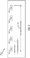
FIG. 1A is a diagram showing the disclosed system for location determination of an emitter using frequency-of-arrival (FOA) measured from a single moving platform, in accordance with at least one example of the present disclosure. -
FIG. 1B is a diagram showing exemplary hardware for the disclosed system for location determination of an emitter using frequency-of-arrival (FOA) measured from a single moving platform, in accordance with at least one example of the present disclosure. -
FIG. 2 is a diagram showing a high-level illustration of the disclosed location determining processing, in accordance with at least one example of the present disclosure. -
FIG. 3 is a diagram showing Doppler history comprising a number of looks (i.e. coherent frequency of arrival (CFOA) measurements), in accordance with at least one example of the present disclosure. -
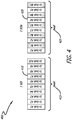
FIG. 4 is a diagram showing exemplary look schedules for monitoring one or two signals of interest (SOIs) with one receiver, in accordance with at least one example of the present disclosure. -
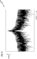
FIG. 5 is a graph showing a magnitude only of an exemplary complex pulse train look reconstructed using complex envelope samples (CES), in accordance with at least one example of the present disclosure. -
FIG. 6 is a diagram showing coherent frequency of arrival (CFOA) estimation for a pulsed emitter using linear regression of phase (LRP), in accordance with at least one example of the present disclosure. -
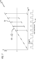
FIG. 7 is graph showing an exemplary estimated CFOA by using the pulse train phase advance, in accordance with at least one example of the present disclosure. -
FIG. 8 is a diagram showing CFOA estimation using the cross correlation of the frequency power spectra (CCFS), in accordance with at least one example of the present disclosure. -
FIG. 9 is a graph showing an exemplary power spectrum of a fast Fourier transform (FFT) of a pulse train look, in accordance with at least one example of the present disclosure. -
FIG. 10 is a graph showing the cross correlation of the power spectrum ofFIG. 9 , in accordance with at least one example of the present disclosure. -
FIG. 11 is a graph showing a comparison of an auto-correlation spectrum of a first look and a cross-correlation spectrum of the first look with another look, in accordance with at least one example of the present disclosure. -
FIG. 12 is a graph showing discrimination statistic distribution and decision logic, in accordance with at least one example of the present disclosure. - The methods and apparatus disclosed herein provide an operative system for location determination of an emitter using frequency-of-arrival (FOA) measured from a single moving platform. In one or more examples, the system of the present disclosure allows for location determination of fixed, pulsed radio frequency (RF) emitters from a moving platform using coherent frequency of arrival (CFOA) Doppler history measurements, which enable geo-discrimination (GeoD) of emitters at known locations or alternatively geo-location of emitters at unknown locations. In at least one example, the present disclosure provides for the determination of the location of the stationary emitters with reference to a moving reference frame that is provided by the moving platform. The term "coherent" is used herein to indicate that the process requires a RF-coherent pulse train, such as that generated by modern radar.
- As previously mentioned above, the precise measurement of frequency is a necessary component of the location process. This is difficult with pulsed signals in that individual pulses are usually not sufficiently long enough to allow for frequency measurement with accuracy necessary to support emitter location determination. Two complementary, coherent frequency of arrival (CFOA) measurement methods that provide the required measurement accuracy are disclosed. These two CFOA methods are: (1) Method 1: CFOA linear regression of phase (LRP), which is more general and necessary for random pulse intervals, but requires demodulation of any intentional intrapulse modulation; and (2) Method 2: CFOA cross-correlated frequency spectra (CCFS), which exploits the spectral line structure of coherent pulsed signals and does not require intrapulse demodulation, but does require a consistent periodic sequence of pulse intervals.
- Both of these methods can be implemented with greatly reduced processing bandwidths that need to be no greater than a small multiple of the pulse repetition frequency (PRF). The benefit is reduced signal buffer size and computational load, with little compromise to measurement accuracy.
- The present disclosure also provides a geo-discrimination (GeoD) technique of distinguishing an emitter location from a set of known possible emitter locations. This GeoD method employs the statistical pattern matching of the Doppler history of a signal measured from a moving platform with the computed Doppler histories of candidate locations (i.e. locations known to emit the same signal). The method exploits the principle of Doppler shift and does not require absolute knowledge of the emitter's frequency. The Doppler history associated with an emitter at a particular radio frequency (RF) is generally unique to the emitter's location. When combined with high Doppler measurement accuracy, the disclosed method of statistical pattern matching reveals the true location of the emitter. It should be noted that although the present disclosure considers only pulsed signals for GeoD, the disclosed technique is equally applicable to continuous wave (CW) signals.
- In the following description, numerous details are set forth in order to provide a more thorough description of the system. It will be apparent, however, to one skilled in the art, that the disclosed system may be practiced without these specific details. In the other instances, well known features have not been described in detail so as not to unnecessarily obscure the system.
- Examples of the present disclosure may be described herein in terms of functional and/or logical components and various processing steps. It should be appreciated that such components may be realized by any number of hardware, software, and/or firmware components configured to perform the specified functions. For example, an example of the present disclosure may employ various integrated circuit components (e.g., memory elements, digital signal processing elements, logic elements, look-up tables, or the like), which may carry out a variety of functions under the control of one or more processors, microprocessors, or other control devices. In addition, those skilled in the art will appreciate that examples of the present disclosure may be practiced in conjunction with other components, and that the system described herein is merely one example of the present disclosure.
- For the sake of brevity, conventional techniques and components related to location determination systems, and other functional aspects of the system (and the individual operating components of the systems) may not be described in detail herein. Furthermore, the connecting lines shown in the various figures contained herein are intended to represent example functional relationships and/or physical couplings between the various elements. It should be noted that many alternative or additional functional relationships or physical connections may be present in an example of the present disclosure.
-
FIG. 1A is a diagram 100 showing the disclosed system for location determination of an emitter using frequency-of-arrival (FOA) measured from a single moving platform, in accordance with at least one example of the present disclosure. In particular, this figure shows an exemplary vehicle (i.e. an aircraft 110) that may be employed as the moving platform for the disclosed system. It should be noted that in alternative examples, other vehicles, than anaircraft 110 as shown inFIG. 1A , may be employed for the moving platform for the disclosed system. Other types of vehicles that may be employed for the moving platform include, but are not limited to, terrestrial vehicles (e.g., trucks or tanks), marine vehicles (e.g., ships or boats), and other types of airborne vehicles (e.g., satellites, such as low earth orbiting (LEO) satellites, medium earth orbiting (MEO) satellites, and geostationary earth orbit (GEO) satellites). - In this figure, the
aircraft 110 and multiple emitters (e.g., transmitting antennas) 120a, 120b, 120c, 120d are shown. Theaircraft 110 comprises a receivingantenna 115 and a receiver (refer to 140 ofFIG. 1B ) to receive radio frequency (RF) signals. The receiveantenna 115 is mounted onto theaircraft 110, which serves as a moving platform for the receiveantenna 115. The moving platform (i.e. the aircraft 110) provides a moving reference frame for the determination of thestationary emitters antenna 115 including, but not limited to, a reflector antenna, a multifeed antenna, and a phased array antenna. In one or more examples, theantenna 115 may comprise one or more antennas. In at least one example, theemitters emitters emitters less emitters FIG. 1A . - In one or more examples, the
emitters emitters emitters - During operation of the disclosed system, as the
aircraft 110 is moving over the Earth, the receiveantenna 115 on theaircraft 110 receives radio frequency (RF) signals 125a, 125b, 125c, 125d transmitted from thestationary emitters signals signals - The
signals FIG. 1B ) on theaircraft 110. Processing circuitry (refer to 145 ofFIG. 1B ) processes thesignals signals -
FIG. 1B is a diagram 130 showing exemplary hardware for the disclosed system for location determination of an emitter using frequency-of-arrival (FOA) measured from a single moving platform, in accordance with at least one example of the present disclosure. In this figure, theantenna 115, thereceiver 140, and theprocessing circuitry 145 are shown. Theprocessing circuitry 145 comprises various different types of units to process thesignals processing circuitry 145 may comprise include, but are not limited to, at least oneprocessor 150, at least onedownconverter 155, at least onefilter 160, at least onedemodulator 165, at least one fast Fourier transform (FFT)processor 170, at least onecorrelator 175, at least oneinterpolator 180, and at least one analog-to-digital converter (ADC) 185. It should be noted that in some examples, at least one processor may simply be employed for some of the units (e.g., an interpolator 180) of theprocessing circuitry 145. - The
processing circuitry 145 may be co-located with thereceiver 140 on theaircraft 110, or may be located at a separate location, which is linked to thereceiver 140 by at least one communications channel that passes at least the minimum necessary data from thesignals FIG. 2 . -
FIG. 2 is a diagram 200 showing a high-level illustration of the disclosed location determining processing, in accordance with at least one example of the present disclosure. This figure shows the high-level process for location processing that comprises (1)coherent look generation 210, (2)Doppler CFOA measurement 220, and (3)location determination 230. In this figure,coherent look generation 210 is first performed, which comprises detecting, capturing, and isolating, by at least one processor, the signal of interest (SOI); and splitting, by at least one processor, the signal for the SOI into n number of "look" segments, where n is greater than one. Then, Doppler CFOA measurement 220 (or Doppler FOA measurement) is performed, which comprises making CFOA measurements (or FOA measurements) for each "look". Then,location determination 230 is performed, which comprises comparing the measured Doppler FOA history of a detected emitter of a known type with the computed Doppler history for known locations of the same emitter type by using a statistical discrimination process, referred to as geo-discrimination (GeoD), or alternatively geo-location of a detected emitter in an unknown location is performed. These three processes (i.e. (1)coherent look generation 210, (2)Doppler CFOA measurement 220, and (3) location determination 230) are described in more detail below. - During the coherent look generation process, the receiver receives the signals transmitted from the emitters. The receiver then transmits to the processing circuitry at least the minimum necessary data from the signals for the processing circuitry to be able to perform the processing. Then, the processing circuitry detects, parameterizes, de-interleaves (as needed), and then classifies and identifies the signals (e.g., identifies which of the signals is the signal(s) of interest (SOI)).
- It should be noted that the receiver utilizes a wide bandwidth front-end, which selects (e.g., by filtering by a bandpass filter (BPF)) the appropriate passband for the signal of interest (SOI). Since frequency measurement is by nature a narrowband process, the signals need not be collected in a bandwidth greater than a small multiple of the larger of the pulse repetition frequency (PRF) and of the inverse pulse duration. This greatly reduces the amount of data that needs to be stored, transferred, and processed.
- Then, after a SOI is identified and isolated, over the total observation time (referred to as the dwell period) 320 (refer to
FIG. 3 ) of the SOI, the SOI data is segregated, by at least one processor, into multiple, separately coherent, "looks" 310a, 310b, 310c, 310d, 310e from which the frequency of arrival (FOA) is measured and used to determine the Doppler shift as a function of time (i.e. the FOA (or Doppler) history).FIG. 3 is a diagram 300 showing Doppler history comprising a number oflooks -
FIG. 4 is a diagram 400 showing exemplary look schedules for monitoring one signal of interest (SOI) 410 or two signals of interest (SOIs) 420 with one receiver, in accordance with at least one example of the present disclosure. As shown in this figure, a dwell (e.g., 10 seconds) 415, 425 is divided into five or more "looks" of 1 second or less (as needed by CFOA). For each look, a FOA measurement is made. The possible duration of each look is bounded by the frequency measurement accuracy requirement on the upper end of thedwell - The required frequency accuracy is determined by operational requirements including, but not limited to, the location of the emitters of interest in the platform field of view (FOV), the platform velocity, and the platform altitude. There is a theoretical limit to frequency measurement accuracy, which is often quoted as the Cramer-Rao Lower Bound. In this case, the accuracy limit to the frequency measurement is inversely proportional to the observation time and inversely proportional to the square root of the signal-to-noise (SNR) ratio. Hence, extending the measurement observation time (i.e. look duration) necessitates the use of multiple looks.
- It should be noted that coherent FOA (CFOA) refers to a process (or processes) that measures the frequency of the underlying carrier signal of a RF-coherent pulse train comprising many pulses. RF coherency is a signal property, and implies that the RF pulse train is generated at baseband (including any intrapulse modulation), and is coherently translated to the operating RF for transmission, where the random phase deviation between pulses is a small fraction of a radian. This kind of signal is enabled by modern electronics and signal processing components, and is now commonly used in radars of all types, but especially in those that measure Doppler for the purpose of detection of moving targets, measuring target velocity, and imaging by synthetic aperture techniques.
- The implementation of CFOA requires additional considerations in the design of receiver systems. Typical Electronic Support Measures (ESM) receiving systems do not store the entire signal during a look. They may only store a description of the pulses in terms of pulse parameters including RF, pulse duration, pulse repetition frequency (PRF), etc. This description is historically referred to as the pulse descriptor word (PDW). But, to perform CFOA, additional information is needed to determine the phase advance of the underlying carrier signal over a train of pulses, assuming that the pulse train is RF coherent. Additional precision time-tagged pre-detected complex (in-phase and quadrature) envelope samples (CES) of the pulses bundled with the PDW are used for reconstruction (refer to
FIG. 5 ) of the pulse trains of the original signal. A radar signal comprising a RF train of pulses is then completely and accurately captured in the CES and PDW data, which in the follow-on processing are used to coherently reconstruct the complex signal (refer toFIG. 5 ) and used to measure FOA (Doppler) history.FIG. 5 is agraph 500 showing a magnitude only of an exemplary complex pulse train look reconstructed using complex envelope samples (CES), in accordance with at least one example of the present disclosure. On this graph, the x-axis denotes time, and the y-axis denotes the signal amplitude. - The following methods are disclosed to determine the Doppler FOA for a look by coherently processing all of the individual pulse phase information. For each method, the complex pre-detected pulse train over each look is coherently reconstructed (refer to
FIG. 5 ) by using the captured complex envelope samples (CES) and the associated time-tags from each pulse of the look. - The system and process for CFOA by linear regression of phase (LRP) are shown in
FIG. 6. FIG. 6 is a diagram 600 showing coherent frequency of arrival (CFOA) estimation for a pulsed emitter using linear regression of phase (LRP), in accordance with at least one example of the present disclosure. - In this figure, first, the reconstructed signal for each look 610a, 610b, 610c, 610n is down-converted 620a, 620b, 620c, 620n, by a downconverter, to near zero frequency, and the type of intrapulse modulation (if any) is determined by at least one processor. The downconverted signals, which are analog, are then digitized 630a, 630b, 630c, 630n, by an analog-to-digital converter (ADC), to produce digital signals.
- Then, if necessary, pulses of the signals are coherently demodulated by a
demodulator - Then, pulse-to-
pulse phase measurements FIG. 7 ). From the unwrapped pulse train phase advance, linear regression (e.g., a least squares fit) and scaling 670a, 670b, 670c, 670n is then performed, by at least one processor, to determine the slope of the unwrapped pulse train phase advance over the look time. -
FIG. 7 isgraph 700 showing an exemplary estimated CFOA by using the pulse train phase advance, in accordance with at least one example of the present disclosure. On this graph, the x-axis denotes time, and the y-axis denotes phase. Also shown is the pulse train envelope 720 (with its pulse repetition interval (PRI) denoted) associated with thegraph 700. - It should be noted that the
graph 700 ofFIG. 7 is notional, and does not accurately account for the actual time between pulses, meaning that the inter-pulse unwrapping can be problematic for low duty-factor pulse trains. To mitigate this problem, a sophisticated use of tuned-histograms may be employed to separate out the ambiguities prior to linear regression. The CFOA measurement (i.e. Δφ/2πΔT, where Δφ is the change in phase and ΔT is the change in time) is theslope 710 of the line fitted to the phase advance during the entire look duration, as is shown inFIG. 7 . - The system and process for CFOA by cross-correlated frequency spectra (CCFS) are shown in
FIG. 8. FIG. 8 is a diagram 800 showing CFOA estimation using the cross correlation of the frequency power spectra (CCFS), in accordance with at least one example of the present disclosure. CFOA by CCFS uses a more optimal approach, which is intrapulse-modulation agnostic and exploits the discrete spectral line structure of an RF-coherent pulse train, working independently of intrapulse modulation type. - As shown in
FIG. 8 , the frequency measurement process comprises first digitizing 820a, 820b, 820c, 820n, by an analog-to-digital converter (ADC), each of thelooks looks looks - Then, the process comprises computing, by at least one fast Fourier transform (FFT) processor, the power spectrum (i.e. the magnitude of the FFT) 830a, 830b, 830c, 830n for each of the digital signals separately. Each power spectrum (e.g., refer to graph 900 of
FIG. 9 ) will exhibit a series of discrete peaks (i.e. spectral lines) with precise spacing equal to the pulse repetition frequency for a constant pulse repetition interval (PRI) pulse train, but more complex for a pulse train with staggered PRI. -
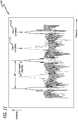
FIG. 9 is agraph 900 showing an exemplary power spectrum of a fast Fourier transform (FFT) of a pulse train look, in accordance with at least one example of the present disclosure. On thisgraph 900, the x-axis denotes frequency, and the y-axis denotes amplitude. Due to Doppler shift, the pulse train spectrum will shift, including all of the spectral lines. The frequency migration versus (vs.) time of the position of these lines between a first look (e.g., Look 1) with other looks (e.g., Look 2, Look 3, Look n) within the observation time provides the CFOA (Doppler) history. - Referring back to
FIG. 8 , after the power spectrum (i.e. the magnitude of the FFT) for each look is obtained, the power spectrum for the first look (i.e. Look 1) is auto-correlated 840a, by at least one correlator, with itself to produce an auto-correlation spectrum (e.g., refer to 1110 ofFIG. 11 ). Also, the power spectrum for the first look (i.e. Look 1) is cross-correlated 840b, 840c, 840n, by at least one correlator, with each of the power spectrums for the other looks (i.e. Look 2, Look 3, Look n) to produce a cross-correlation spectrum (e.g., refer to 1000 ofFIG. 10 and 1120 ofFIG. 11 ) for each of the other looks (i.e. Look 2, Look 3, Look n).FIG. 10 is agraph 1000 showing an exemplary cross correlation of the power spectrum ofFIG. 9 , in accordance with at least one example of the present disclosure. On thisgraph 1000, the x-axis denotes frequency, and the y-axis denotes amplitude. -
FIG. 11 is agraph 1100 showing a comparison of an auto-correlation spectrum 1110 of a first look (e.g., Look 1) and across-correlation spectrum 1120 of the first look (e.g., Look 1) with another look (e.g., Look 2, Look 3, or Look n), in accordance with at least one example of the present disclosure. On thisgraph 1100, the x-axis denotes frequency, and the y-axis denotes amplitude. The auto-correlation spectrum 1110 (with its pulse repetition frequency (PRF) denoted) essentially serves as a reference. That is, a comparison of the auto-correlation spectrum 1110 and thecross-correlation spectrum 1120 with another look (e.g., Look 2, Look 3, or Look n) is used to determine how much the lines have migrated between the first look (e.g., Look 1) and the subsequent looks (e.g., Look 1, Look 2, Look n) to determine the Doppler history for CFOA. The auto-correlation of the first look (i.e. Look 1) (i.e. the auto-correlation spectrum 1110) and then the cross-correlation between the first look (i.e. Look 1) and subsequent looks (i.e. Look 2, Look 3, Look n) (i.e. the cross-correlation spectrum 1120) provides a means of precisely measuring the frequency advance look-to-look. - Referring back to
FIG. 8 , after the power spectrum of the first look (i.e. Look 1) is auto-correlated 840a with itself to produce an auto-correlation spectrum, and the power spectrum for the first look (i.e. Look 1) is cross-correlated 840b, 840c, 840n with each of the power spectrums for the other looks (i.e. Look 2, Look 3, Look n) to produce cross-correlation spectra, the spectra are then interpolated 850a, 850b, 850n to produce interpolated signals. Then,CFOA measurements - Other methods may be used to determine the CFOA of multiple pulses. The conventionally used complex ambiguity function (CAF) method can be used to compare looks to resolve frequency shifts after lining up the time correlation. This method is more computationally expensive than the disclosed
Method 1 andMethod 2 discussed above because this method requires many CAF points to find the maximum peak. There are also concerns when using this method regarding finding the local maxima instead of the total maximum. And, there are difficulties with this method with linear frequency modulation (LFM) signals creating a larger area of ambiguity. Also, this method cannot be employed for random pulse patterns. However, once processed, the output of the CFOAs from this method may be used in further processing for location determination, which is described in detail below. - This section describes the location determination using the Doppler histories obtained above. The location determination can be done by using either CFOA for signals with pulses or the more generic frequency of arrival (FOA) for continuous wave (CW) signals that do not require the extra coherent processing.
- The location determination process comprises computing Doppler histories for each location, i, as observed over the same time period as the above measured FOA history, using the best available platform state vector data. The underlying principle of the technique is that, in general, each location will have a unique FOA history due to the differences in location with respect to the vehicle state vector.
- Geo-location will be performed when the emitters are not at known locations. For geo-location of the emitters, standard geo-location can be performed using the FOA data found for each look. This results in a region of error depending upon the quality of the received signal (usually represented by the signal to noise ratio (SNR)), the duration of the look, the duration of the dwell, the number of looks, and the quality of the receiver. This error is often defined in terms of a circular or elliptical region corresponding to a probability that the resulting geolocation will fall within that region. In this scheme, the metrics are usually the radius of the circle, circular error probable (CEP), or the semi-major axis of the ellipse, elliptical error probable (EEP). In one or more examples, an algorithm for standard geolocation using the FOA data found for each look is run on at least one processor to perform geolocation of the emitters.
- Geo-discrimination (GeoD) will be performed when there are a finite number of emitters at known locations. For GeoD, the matching of the measured FOA history to the known possible emitter locations is easier than geolocation since only a discrimination of which known location is most likely radiating the SOI is performed. GeoD takes the FOA histories from the emitters at candidate locations on a pair-wise basis using a decision boundary threshold Tf computed for each candidate pair following the Sequential Decision Test (SDT). This threshold enables a trade between the probability of an error and the probability of making no decision, an important factor in assuring control over the error rate. For M possible number of emitter locations and M(M-1)/2 pairwise combinations, the algorithm, run on at least one processor, decides the location where the measured FOA history best matches the measured FOA history. Not all M(M-1)/2 combinations need to be tested, since once a candidate emitter location fails a pair-wise test, it can be removed from any further testing. A guarantee of a minimum probability of error is when all but one are eliminated. No decision is made if any of the pair-wise matches are ambiguous.
- The decision logic for each candidate location pair is illustrated in
FIG. 12 , where σs is the standard deviation of the decision statistic, and µ S/A and µ S/B are the mean values of the decision statistic given A and B, respectively. The value of the decision boundary threshold, Tf , is determined from the statistics of measured and computed FOA histories.FIG. 12 is agraph 1200 showing discrimination statistic distribution and decision logic, in accordance with at least one example of the present disclosure. On thisgraph 1200, the x-axis denotes the discrimination statistic (S), and the y-axis denotes probability. A detailed discussion regarding the sequential discrimination test used to determine the discrimination statistic distribution and decision logic shown onFIG. 12 is provided in the section below. In one or more examples, an algorithm for GeoD that applies the FOA histories from the emitters at known locations to the sequential discrimination test is run on at least one processor to perform GeoD of the emitters. - Let X = [X 1 ,X 2 ,...,Xn ] denote independent random samples taken from one of two different Gaussian stochastic processes A or B (refer to
FIG. 12 ). Assume both A and B have a common stationary variance σ 2, and there occurrence is mutually exclusive with P(A)+P(B)= 1 . The processes A and B are only distinguished by the means, with A having a history of varying means η = [η 1,η 2,...,ηn ] which are known in advance, and process B having a history of varying means v = [v 1 , v 2,..., vn ] that are also known. - The primary objective is to design a sequential test based on the random samples that will discriminate between process A or process B . Secondary objectives are (1) design the test to insure that the probability of making a discrimination error is at most pf ; and (2) derive and expression the probability of successful discrimination.
- A sequential test is the formulation of a statistic S = S(x1,x2,...,xn ) and two thresholds k 1 < k2 such that:

- The test is called sequential because the statistic S and thresholds k 1 , k 2 can be updated as more samples become available, which provide the opportunity to make a more accurate decision.
- The statistic S is based the likelihood ratio:


- To statistic S and thresholds k 1 , k2 define the test, and the best statistic, guaranteed by the Neyman-Pearson Theorem, is derived from the inequality:


- Let


- From (0.7) we define the discrimination statistic S to be:

- The notation S|A means the statistic S is evaluated with samples that came from process A , and S|B means the statistic S is evaluated with samples that came from process B . Notice that S|A is a normally distributed random variable with mean:


- Similarly, S|B is normally distributed with mean:


- From which it is observed that:

- Using the decision logic (0.1), a discrimination error is made only if:

- Thus, in order to set the probability of making an error to pf we must choose k 1 and k 2 so that:

- Also, a reasonable choice here is to set k 1 and k 2 so that both probabilities in (0.15) are equal, that is:


- Evaluating the former results in:


- Where, in both cases, the quantities:


- The relationship between pf and Tf is denoted by either p f = N -1(Tf ) or Tf = N -1(pf ). Using this notation, it follows that:

- Equivalently, substituting (0.9), (0.10), (0.11) and (0.12) into (0.22) yields:

- From equations (0.23) the probability of discrimination can be calculated:

- First,

- Similarly,

- Therefore,

- Equation (0.27) is the desired equation describing the probability of discrimination based on knowledge of the mean histories η and v, the variance of the random samples σ 2 and the probability of error pf = N -1(Tf ).
- There are several important sources of GeoD error that are considered as part of the system design and evaluation. As with geolocation, in general, GeoD is critically dependent on FOA errors and collection geometry. In fact, the effect of measurement error on FOA GeoD is virtually identical to that of FOA geolocation. The primary sources of FOA error are random frequency measurement error (which is primarily due to thermal noise), RF instability of the SOI, and the master oscillator of the collection platform.
- Random frequency measurement error is critically dependent on the measurement method. But by careful design of the measurement algorithm, the measurement error can approach the Cramer-Rao Lower Bound (CRLB), which is inversely proportional to integration time and the square root of the SNR.
- The RF instability of the SOI is uncontrolled and systematic. Although the signals of interest are coherent, the actual RF stability of the signals is essentially unknown.
- The master oscillator of the collection platform is systematic and controllable, which is determined by the frequency stability of the reference oscillator of the collection system. Commercially available ovenized crystal oscillators marketed in the United States typically have frequency stabilities of about 0.05 Hertz/Gigahertz (Hz/GHz) for averaging time up to 100 seconds, which is more than adequate for the FOA GeoD function.
- Another possible source of error for SOIs with RFs below about 200 megahertz (MHz) is the ionosphere. In the ionosphere, the propagation path is refracted, and the Doppler shift deviates from the line of sight (LOS) behavior and is difficult to predict. This is particularly the case at low grazing angles at ionosphere highs. For certain times of the day, the season, and phase of the solar cycle, the FOA measurements may need to be restricted to the higher grazing angles for SOIs with RFs below about 200 MHz.
- Although particular examples have been shown and described, it should be understood that the above discussion is not intended to limit the scope of these examples. While examples and variations of the many aspects have been disclosed and described herein, such disclosure is provided for purposes of explanation and illustration only. Thus, various changes and modifications may be made without departing from the scope of the claims.
- Where methods described above indicate certain events occurring in certain order, those of ordinary skill in the art having the benefit of this disclosure would recognize that the ordering may be modified and that such modifications are in accordance with the variations of the present disclosure. Additionally, parts of methods may be performed concurrently in a parallel process when possible, as well as performed sequentially. In addition, more parts or less part of the methods may be performed.
- Although certain illustrative examples and methods have been disclosed herein, it can be apparent from the foregoing disclosure to those skilled in the art that variations and modifications of such examples and methods can be made without departing from the true scope of the art disclosed. Many other examples of the art disclosed exist, each differing from others in matters of detail only. Accordingly, it is intended that the art disclosed shall be limited only to the extent required by the appended claims and the rules and principles of applicable law.
Claims (14)
- A method for location determination, the method comprising:receiving, by an antenna (115) mounted on a moving platform (110), a plurality of signals (125) transmitted from a plurality of emitters (120);identifying a signal of interest, SOI, (410) from the signals (125), whereby the signal of interest comprises a coherent pulse train;splitting the SOI (410) into a plurality of look segments (310);determining frequency of arrival, FOA, measurements from the look segments; anddetermining a location of the emitter (120), from the plurality of emitters (120), that transmitted the SOI (410) by using the FOA measurements; wherein the determining of the FOA measurements comprises:downconverting (620) each of the look segments (310) to generate downconverted look segments;coherently demodulating (640) each of the downconverted look segments to generate demodulated look segments;obtaining pulse-to-pulse phase measurements (650) from each of the demodulated look segments;unwrapping the pulse-to-pulse phase measurements (660) to generate unwrapped pulse train phase advances (700);performing linear regression and scaling (670) to determine a slope of each of the unwrapped pulse train phase advances (700); anddetermining (220) the FOA measurements (220) from the slope (710) of each of the unwrapped pulse train phase advances (700).
- The method of claim 1, when the emitters (120) are at unknown locations, the determining of the location of the emitter (120) that transmitted the SOI (410) by using the FOA measurements (220) comprises: performing geo-location by using the FOA measurements (220).
- The method of any one of the preceding claims, wherein the location of the emitter (120) that transmitted the SOI (410) is a location known to have an emitter (120) of a same type as the emitter (120) that transmitted the SOI (410).
- The method of any one of the preceding claims, wherein the signals are radio frequency, RF, signals.
- The method of any one of the preceding claims, wherein the moving platform (110) is a vehicle (110).
- The method of claim 5, wherein the vehicle (110) is an airborne vehicle (110), a terrestrial vehicle, or a marine vehicle.
- The method of any one the preceding claims, wherein at least one of:
each of the emitters (120) is a known type of emitter (120). - The method of any one of the preceding claims, wherein the antenna (115) is a reflector antenna (115), a multifeed antenna, or a phased array antenna.
- The method of any one of the preceding claims, wherein
the FOA measurements (220) are coherent frequency of arrival, CFOA, measurements (220). - A system for location determination, the system comprising:an antenna (115), mounted on a moving platform (110), to receive a plurality of signals (125) transmitted from a plurality of emitters (120); andprocessing circuitry (145) configured to identify a signal of interest, SOI, (410) from the signals (125), whereby the signal of interest comprises a coherent pulsed signal; to split the SOI (410) into a plurality of look segments (310), to determine frequency of arrival, FOA, measurements (220) from the look segments (310), and to determine a location of the emitter (120), from the plurality of emitters (120), that transmitted the SOI (410) by using the FOA measurements (220); wherein when the processing circuitry (145) is configured to determine the FOA measurements (220), the processing circuitry (145) is further configured: to downconvert (620) each of the look segments (310) to generate downconverted look segments, to coherently demodulate (640) each of the downconverted look segments to generate demodulated look segments, to obtain pulse-to-pulse phase measurements (650) from each of the demodulated look segments, to unwrap the pulse-to-pulse phase measurements (660) to generate unwrapped pulse train phase advances (700), to perform linear regression and scaling (670) to determine a slope (710) of each of the unwrapped pulse train phase advances (700), and to determine the FOA measurements (220) from the slope (710) of each of the unwrapped pulse train phase advances (700).
- The system of claim 10, wherein when the emitters (120) are at unknown locations, the processing circuitry (145) is configured to determine the location of the emitter (120) that transmitted the SOI (410) by using the FOA measurements (220) by performing geo-location by using the FOA measurements (220).
- The system of any one of claims 10-11, wherein the moving platform (115) is a vehicle (115).
- The system of claim 12, wherein the processing circuitry is located on the vehicle or at a different location other than the vehicle.
- The system of any one of claims 10-13, wherein the processing circuitry comprises at least one of a processor, a downconverter, a filter, a demodulator, a fast Fourier transform (FFT) processor, an interpolator, or an analog-to-digital converter (ADC).
Applications Claiming Priority (2)
| Application Number | Priority Date | Filing Date | Title |
|---|---|---|---|
| US201762571155P | 2017-10-11 | 2017-10-11 | |
| US15/840,968 US10901065B2 (en) | 2017-10-11 | 2017-12-13 | Location determination of an emitter using frequency-of-arrival (FOA) measured from a single moving platform |
Publications (3)
| Publication Number | Publication Date |
|---|---|
| EP3480619A2 EP3480619A2 (en) | 2019-05-08 |
| EP3480619A3 EP3480619A3 (en) | 2019-08-14 |
| EP3480619B1 true EP3480619B1 (en) | 2021-03-24 |
Family
ID=63683788
Family Applications (1)
| Application Number | Title | Priority Date | Filing Date |
|---|---|---|---|
| EP18196632.6A Active EP3480619B1 (en) | 2017-10-11 | 2018-09-25 | Location determination of an emitter using frequency-of-arrival (foa) measured from a single moving platform |
Country Status (5)
| Country | Link |
|---|---|
| US (1) | US10901065B2 (en) |
| EP (1) | EP3480619B1 (en) |
| JP (1) | JP7240127B2 (en) |
| CN (1) | CN109655820A (en) |
| CA (1) | CA3008370C (en) |
Families Citing this family (4)
| Publication number | Priority date | Publication date | Assignee | Title |
|---|---|---|---|---|
| WO2017149596A1 (en) * | 2016-02-29 | 2017-09-08 | 三菱電機株式会社 | Radar device |
| CN113203376B (en) * | 2021-04-19 | 2022-11-11 | 深圳市安全守护科技有限公司 | Position deviation rectifying method, device, equipment and computer readable storage medium |
| CN114415122B (en) * | 2022-01-27 | 2023-03-28 | 电子科技大学 | High-speed target accumulation detection method based on frequency domain segmentation processing |
| US11923892B2 (en) * | 2022-05-19 | 2024-03-05 | Raytheon Company | Method and architecture for positive identification and verification of multi-mode frequency hopping signals |
Family Cites Families (24)
| Publication number | Priority date | Publication date | Assignee | Title |
|---|---|---|---|---|
| JPH02504673A (en) * | 1987-08-10 | 1990-12-27 | ケンブリッジ・ポジショニング・システムズ・リミテッド | Navigation and tracking system |
| US5526001A (en) | 1992-12-11 | 1996-06-11 | Litton Systems Inc. | Precise bearings only geolocation in systems with large measurements bias errors |
| US5717406A (en) * | 1995-06-07 | 1998-02-10 | Sanconix Inc. | Enhanced position calculation |
| US5973643A (en) * | 1997-04-11 | 1999-10-26 | Corsair Communications, Inc. | Method and apparatus for mobile emitter location |
| US6185486B1 (en) | 1998-04-28 | 2001-02-06 | Mcdonnell Douglas Corporation | Air vehicle landing/takeoff area mapping system and method |
| US6522296B2 (en) * | 2001-06-25 | 2003-02-18 | Harris Corporation | Method and system for calibrating wireless location systems |
| EP2035854B1 (en) * | 2006-06-27 | 2014-04-16 | Telefonaktiebolaget LM Ericsson (publ) | A radio frequency emitter detection and location method and system |
| US7626546B2 (en) | 2007-09-27 | 2009-12-01 | L-3 Communications Integrated Systems L.P. | Methods and systems for detection and location of multiple emitters |
| JP2012083264A (en) * | 2010-10-13 | 2012-04-26 | Mitsubishi Electric Corp | Positioning method |
| US9285454B2 (en) * | 2011-03-04 | 2016-03-15 | Zih Corp. | Method, apparatus, and computer program product for processing received signals for locating |
| US9128173B1 (en) | 2011-05-25 | 2015-09-08 | Leidos, Inc. | Machine and process for self localization using doppler |
| US8866672B2 (en) | 2012-04-05 | 2014-10-21 | L-3 Communications Integrated Systems Lp | Cooperative systems and methods for TDOA-based emitter location |
| US9110147B1 (en) * | 2012-11-02 | 2015-08-18 | Sandia Corporation | Differential emitter geolocation |
| US9113431B2 (en) * | 2012-11-16 | 2015-08-18 | Qualcomm Incorporated | Method for corroboration and transferring trust between network databases for enhanced positioning accuracy |
| US9562961B1 (en) * | 2013-02-28 | 2017-02-07 | The Boeing Company | Apparatus, method, and system for estimating the angle of arrival of a signal |
| US20170208495A1 (en) | 2013-03-15 | 2017-07-20 | DGS Global Systems, Inc. | Systems, methods, and devices for geolocation with deployable large scale arrays |
| US9702960B2 (en) | 2013-03-15 | 2017-07-11 | Raytheon Company | Frequency difference of arrival (FDOA) for geolocation |
| US9709662B2 (en) | 2014-08-18 | 2017-07-18 | The Boeing Company | Systems and methods for determining a position of a transmitter of a bistatic radar system |
| FR3031257B1 (en) * | 2014-12-31 | 2018-03-30 | Thales | RADAR SIGNAL DISENTING METHOD |
| CA2975448C (en) * | 2015-02-09 | 2019-12-31 | Concentric Real Time, Llc | Radio receiver for determining location of a signal source |
| US9891306B2 (en) * | 2015-07-02 | 2018-02-13 | Raytheon Company | Geolocating a remote emitter |
| IL240281B (en) | 2015-08-02 | 2020-05-31 | Fiereizen Moshe | System and method for locating a signal source |
| DE102015120733B4 (en) * | 2015-11-30 | 2017-11-02 | Infineon Technologies Ag | Radar device with phase noise estimation |
| US20180231632A1 (en) | 2017-02-15 | 2018-08-16 | Raytheon Company | Multi-receiver geolocation using differential gps |
-
2017
- 2017-12-13 US US15/840,968 patent/US10901065B2/en active Active
-
2018
- 2018-06-13 CA CA3008370A patent/CA3008370C/en active Active
- 2018-08-28 CN CN201810989405.0A patent/CN109655820A/en active Pending
- 2018-09-25 EP EP18196632.6A patent/EP3480619B1/en active Active
- 2018-10-10 JP JP2018191927A patent/JP7240127B2/en active Active
Non-Patent Citations (1)
| Title |
|---|
| None * |
Also Published As
| Publication number | Publication date |
|---|---|
| JP7240127B2 (en) | 2023-03-15 |
| EP3480619A2 (en) | 2019-05-08 |
| US10901065B2 (en) | 2021-01-26 |
| CA3008370C (en) | 2022-11-29 |
| EP3480619A3 (en) | 2019-08-14 |
| JP2019090791A (en) | 2019-06-13 |
| CA3008370A1 (en) | 2019-04-11 |
| CN109655820A (en) | 2019-04-19 |
| US20190107599A1 (en) | 2019-04-11 |
Similar Documents
| Publication | Publication Date | Title |
|---|---|---|
| EP3480619B1 (en) | Location determination of an emitter using frequency-of-arrival (foa) measured from a single moving platform | |
| EP3015880B1 (en) | Ambiguity resolution in a doppler radar system | |
| US9921305B2 (en) | Radar apparatus and object sensing method | |
| EP1902329B1 (en) | System and method for passively estimating angle and range of a source using signal samples collected simulataneously from a multi-aperture antenna | |
| EP1970728B1 (en) | DSSS radar, method implemented by radar and computer-readable storage medium | |
| EP3324205B1 (en) | Decentralised radar system | |
| EP1651978B1 (en) | An improved process for phase-derived range measurements | |
| US8884810B2 (en) | Compact beacon radar and full ATC services system | |
| US8179317B2 (en) | Method and apparatus for passive geolocation using synthetic-aperture processing | |
| Markkanen et al. | Real-time space debris monitoring with EISCAT | |
| EP2391022A1 (en) | Classification of interference | |
| US5708443A (en) | Method and apparatus for using signal doppler change to resolve long baseline interferometer ambiguous phase change measurements for locating a radar emitter | |
| US11555881B2 (en) | Locating method for localizing at least one object using wave-based signals and locating system | |
| Pegoraro et al. | JUMP: Joint communication and sensing with Unsynchronized transceivers Made Practical | |
| Anghel et al. | Simplified bistatic SAR imaging with a fixed receiver and TerraSAR-X as transmitter of opportunity-First results | |
| CN113189554A (en) | Processing method of radar measured echo data, electronic equipment and storage medium | |
| Kelner et al. | Influence of the frequency stability on the emitter position in SDF method | |
| Navrátil et al. | Exploiting terrestrial positioning signals to enable a low-cost passive radar | |
| JP2000314773A (en) | Short wave marine rader observation device | |
| Pascual et al. | The microwave interferometric reflectometer. Part II: Back-end and processor descriptions | |
| Foreman | Application of the CLEAN detector to low signal to noise ratio targets | |
| Li et al. | A non-uniform DFT-based batch acquisition method for enhanced DME (eDME) Carrier Phase: Concept, simulations, and flight test results | |
| US10509118B2 (en) | Systems and methods for measuring wave fields of a body of water | |
| RU2555865C2 (en) | Method of measuring altitude and radar altimeter with continuous chirp signal using said method | |
| RU2550082C1 (en) | Altitude measurement method and altitude measurement device with continuous lfm signal using method |
Legal Events
| Date | Code | Title | Description |
|---|---|---|---|
| PUAI | Public reference made under article 153(3) epc to a published international application that has entered the european phase |
Free format text: ORIGINAL CODE: 0009012 |
|
| STAA | Information on the status of an ep patent application or granted ep patent |
Free format text: STATUS: REQUEST FOR EXAMINATION WAS MADE |
|
| 17P | Request for examination filed |
Effective date: 20180925 |
|
| AK | Designated contracting states |
Kind code of ref document: A2 Designated state(s): AL AT BE BG CH CY CZ DE DK EE ES FI FR GB GR HR HU IE IS IT LI LT LU LV MC MK MT NL NO PL PT RO RS SE SI SK SM TR |
|
| AX | Request for extension of the european patent |
Extension state: BA ME |
|
| PUAL | Search report despatched |
Free format text: ORIGINAL CODE: 0009013 |
|
| AK | Designated contracting states |
Kind code of ref document: A3 Designated state(s): AL AT BE BG CH CY CZ DE DK EE ES FI FR GB GR HR HU IE IS IT LI LT LU LV MC MK MT NL NO PL PT RO RS SE SI SK SM TR |
|
| AX | Request for extension of the european patent |
Extension state: BA ME |
|
| RIC1 | Information provided on ipc code assigned before grant |
Ipc: G01S 5/02 20100101AFI20190710BHEP Ipc: G01S 7/02 20060101ALI20190710BHEP |
|
| GRAP | Despatch of communication of intention to grant a patent |
Free format text: ORIGINAL CODE: EPIDOSNIGR1 |
|
| STAA | Information on the status of an ep patent application or granted ep patent |
Free format text: STATUS: GRANT OF PATENT IS INTENDED |
|
| INTG | Intention to grant announced |
Effective date: 20200508 |
|
| GRAJ | Information related to disapproval of communication of intention to grant by the applicant or resumption of examination proceedings by the epo deleted |
Free format text: ORIGINAL CODE: EPIDOSDIGR1 |
|
| STAA | Information on the status of an ep patent application or granted ep patent |
Free format text: STATUS: REQUEST FOR EXAMINATION WAS MADE |
|
| INTC | Intention to grant announced (deleted) | ||
| GRAP | Despatch of communication of intention to grant a patent |
Free format text: ORIGINAL CODE: EPIDOSNIGR1 |
|
| STAA | Information on the status of an ep patent application or granted ep patent |
Free format text: STATUS: GRANT OF PATENT IS INTENDED |
|
| INTG | Intention to grant announced |
Effective date: 20201106 |
|
| GRAS | Grant fee paid |
Free format text: ORIGINAL CODE: EPIDOSNIGR3 |
|
| GRAA | (expected) grant |
Free format text: ORIGINAL CODE: 0009210 |
|
| STAA | Information on the status of an ep patent application or granted ep patent |
Free format text: STATUS: THE PATENT HAS BEEN GRANTED |
|
| AK | Designated contracting states |
Kind code of ref document: B1 Designated state(s): AL AT BE BG CH CY CZ DE DK EE ES FI FR GB GR HR HU IE IS IT LI LT LU LV MC MK MT NL NO PL PT RO RS SE SI SK SM TR |
|
| REG | Reference to a national code |
Ref country code: GB Ref legal event code: FG4D |
|
| REG | Reference to a national code |
Ref country code: CH Ref legal event code: EP |
|
| REG | Reference to a national code |
Ref country code: IE Ref legal event code: FG4D |
|
| REG | Reference to a national code |
Ref country code: AT Ref legal event code: REF Ref document number: 1375047 Country of ref document: AT Kind code of ref document: T Effective date: 20210415 Ref country code: DE Ref legal event code: R096 Ref document number: 602018014296 Country of ref document: DE |
|
| REG | Reference to a national code |
Ref country code: LT Ref legal event code: MG9D |
|
| PG25 | Lapsed in a contracting state [announced via postgrant information from national office to epo] |
Ref country code: NO Free format text: LAPSE BECAUSE OF FAILURE TO SUBMIT A TRANSLATION OF THE DESCRIPTION OR TO PAY THE FEE WITHIN THE PRESCRIBED TIME-LIMIT Effective date: 20210624 Ref country code: BG Free format text: LAPSE BECAUSE OF FAILURE TO SUBMIT A TRANSLATION OF THE DESCRIPTION OR TO PAY THE FEE WITHIN THE PRESCRIBED TIME-LIMIT Effective date: 20210624 Ref country code: GR Free format text: LAPSE BECAUSE OF FAILURE TO SUBMIT A TRANSLATION OF THE DESCRIPTION OR TO PAY THE FEE WITHIN THE PRESCRIBED TIME-LIMIT Effective date: 20210625 Ref country code: FI Free format text: LAPSE BECAUSE OF FAILURE TO SUBMIT A TRANSLATION OF THE DESCRIPTION OR TO PAY THE FEE WITHIN THE PRESCRIBED TIME-LIMIT Effective date: 20210324 Ref country code: HR Free format text: LAPSE BECAUSE OF FAILURE TO SUBMIT A TRANSLATION OF THE DESCRIPTION OR TO PAY THE FEE WITHIN THE PRESCRIBED TIME-LIMIT Effective date: 20210324 |
|
| PG25 | Lapsed in a contracting state [announced via postgrant information from national office to epo] |
Ref country code: RS Free format text: LAPSE BECAUSE OF FAILURE TO SUBMIT A TRANSLATION OF THE DESCRIPTION OR TO PAY THE FEE WITHIN THE PRESCRIBED TIME-LIMIT Effective date: 20210324 Ref country code: LV Free format text: LAPSE BECAUSE OF FAILURE TO SUBMIT A TRANSLATION OF THE DESCRIPTION OR TO PAY THE FEE WITHIN THE PRESCRIBED TIME-LIMIT Effective date: 20210324 Ref country code: SE Free format text: LAPSE BECAUSE OF FAILURE TO SUBMIT A TRANSLATION OF THE DESCRIPTION OR TO PAY THE FEE WITHIN THE PRESCRIBED TIME-LIMIT Effective date: 20210324 |
|
| REG | Reference to a national code |
Ref country code: NL Ref legal event code: MP Effective date: 20210324 |
|
| REG | Reference to a national code |
Ref country code: AT Ref legal event code: MK05 Ref document number: 1375047 Country of ref document: AT Kind code of ref document: T Effective date: 20210324 |
|
| PG25 | Lapsed in a contracting state [announced via postgrant information from national office to epo] |
Ref country code: NL Free format text: LAPSE BECAUSE OF FAILURE TO SUBMIT A TRANSLATION OF THE DESCRIPTION OR TO PAY THE FEE WITHIN THE PRESCRIBED TIME-LIMIT Effective date: 20210324 |
|
| PG25 | Lapsed in a contracting state [announced via postgrant information from national office to epo] |
Ref country code: AT Free format text: LAPSE BECAUSE OF FAILURE TO SUBMIT A TRANSLATION OF THE DESCRIPTION OR TO PAY THE FEE WITHIN THE PRESCRIBED TIME-LIMIT Effective date: 20210324 Ref country code: SM Free format text: LAPSE BECAUSE OF FAILURE TO SUBMIT A TRANSLATION OF THE DESCRIPTION OR TO PAY THE FEE WITHIN THE PRESCRIBED TIME-LIMIT Effective date: 20210324 Ref country code: EE Free format text: LAPSE BECAUSE OF FAILURE TO SUBMIT A TRANSLATION OF THE DESCRIPTION OR TO PAY THE FEE WITHIN THE PRESCRIBED TIME-LIMIT Effective date: 20210324 Ref country code: CZ Free format text: LAPSE BECAUSE OF FAILURE TO SUBMIT A TRANSLATION OF THE DESCRIPTION OR TO PAY THE FEE WITHIN THE PRESCRIBED TIME-LIMIT Effective date: 20210324 Ref country code: LT Free format text: LAPSE BECAUSE OF FAILURE TO SUBMIT A TRANSLATION OF THE DESCRIPTION OR TO PAY THE FEE WITHIN THE PRESCRIBED TIME-LIMIT Effective date: 20210324 |
|
| PG25 | Lapsed in a contracting state [announced via postgrant information from national office to epo] |
Ref country code: PT Free format text: LAPSE BECAUSE OF FAILURE TO SUBMIT A TRANSLATION OF THE DESCRIPTION OR TO PAY THE FEE WITHIN THE PRESCRIBED TIME-LIMIT Effective date: 20210726 Ref country code: PL Free format text: LAPSE BECAUSE OF FAILURE TO SUBMIT A TRANSLATION OF THE DESCRIPTION OR TO PAY THE FEE WITHIN THE PRESCRIBED TIME-LIMIT Effective date: 20210324 Ref country code: RO Free format text: LAPSE BECAUSE OF FAILURE TO SUBMIT A TRANSLATION OF THE DESCRIPTION OR TO PAY THE FEE WITHIN THE PRESCRIBED TIME-LIMIT Effective date: 20210324 Ref country code: SK Free format text: LAPSE BECAUSE OF FAILURE TO SUBMIT A TRANSLATION OF THE DESCRIPTION OR TO PAY THE FEE WITHIN THE PRESCRIBED TIME-LIMIT Effective date: 20210324 Ref country code: IS Free format text: LAPSE BECAUSE OF FAILURE TO SUBMIT A TRANSLATION OF THE DESCRIPTION OR TO PAY THE FEE WITHIN THE PRESCRIBED TIME-LIMIT Effective date: 20210724 |
|
| REG | Reference to a national code |
Ref country code: DE Ref legal event code: R097 Ref document number: 602018014296 Country of ref document: DE |
|
| PG25 | Lapsed in a contracting state [announced via postgrant information from national office to epo] |
Ref country code: DK Free format text: LAPSE BECAUSE OF FAILURE TO SUBMIT A TRANSLATION OF THE DESCRIPTION OR TO PAY THE FEE WITHIN THE PRESCRIBED TIME-LIMIT Effective date: 20210324 Ref country code: AL Free format text: LAPSE BECAUSE OF FAILURE TO SUBMIT A TRANSLATION OF THE DESCRIPTION OR TO PAY THE FEE WITHIN THE PRESCRIBED TIME-LIMIT Effective date: 20210324 Ref country code: ES Free format text: LAPSE BECAUSE OF FAILURE TO SUBMIT A TRANSLATION OF THE DESCRIPTION OR TO PAY THE FEE WITHIN THE PRESCRIBED TIME-LIMIT Effective date: 20210324 |
|
| PLBE | No opposition filed within time limit |
Free format text: ORIGINAL CODE: 0009261 |
|
| STAA | Information on the status of an ep patent application or granted ep patent |
Free format text: STATUS: NO OPPOSITION FILED WITHIN TIME LIMIT |
|
| PG25 | Lapsed in a contracting state [announced via postgrant information from national office to epo] |
Ref country code: SI Free format text: LAPSE BECAUSE OF FAILURE TO SUBMIT A TRANSLATION OF THE DESCRIPTION OR TO PAY THE FEE WITHIN THE PRESCRIBED TIME-LIMIT Effective date: 20210324 |
|
| 26N | No opposition filed |
Effective date: 20220104 |
|
| REG | Reference to a national code |
Ref country code: CH Ref legal event code: PL |
|
| REG | Reference to a national code |
Ref country code: BE Ref legal event code: MM Effective date: 20210930 |
|
| PG25 | Lapsed in a contracting state [announced via postgrant information from national office to epo] |
Ref country code: IS Free format text: LAPSE BECAUSE OF FAILURE TO SUBMIT A TRANSLATION OF THE DESCRIPTION OR TO PAY THE FEE WITHIN THE PRESCRIBED TIME-LIMIT Effective date: 20210724 Ref country code: MC Free format text: LAPSE BECAUSE OF FAILURE TO SUBMIT A TRANSLATION OF THE DESCRIPTION OR TO PAY THE FEE WITHIN THE PRESCRIBED TIME-LIMIT Effective date: 20210324 |
|
| PG25 | Lapsed in a contracting state [announced via postgrant information from national office to epo] |
Ref country code: LU Free format text: LAPSE BECAUSE OF NON-PAYMENT OF DUE FEES Effective date: 20210925 Ref country code: IE Free format text: LAPSE BECAUSE OF NON-PAYMENT OF DUE FEES Effective date: 20210925 Ref country code: BE Free format text: LAPSE BECAUSE OF NON-PAYMENT OF DUE FEES Effective date: 20210930 |
|
| PG25 | Lapsed in a contracting state [announced via postgrant information from national office to epo] |
Ref country code: LI Free format text: LAPSE BECAUSE OF NON-PAYMENT OF DUE FEES Effective date: 20210930 Ref country code: CH Free format text: LAPSE BECAUSE OF NON-PAYMENT OF DUE FEES Effective date: 20210930 |
|
| PG25 | Lapsed in a contracting state [announced via postgrant information from national office to epo] |
Ref country code: IT Free format text: LAPSE BECAUSE OF FAILURE TO SUBMIT A TRANSLATION OF THE DESCRIPTION OR TO PAY THE FEE WITHIN THE PRESCRIBED TIME-LIMIT Effective date: 20210324 |
|
| P01 | Opt-out of the competence of the unified patent court (upc) registered |
Effective date: 20230516 |
|
| PG25 | Lapsed in a contracting state [announced via postgrant information from national office to epo] |
Ref country code: CY Free format text: LAPSE BECAUSE OF FAILURE TO SUBMIT A TRANSLATION OF THE DESCRIPTION OR TO PAY THE FEE WITHIN THE PRESCRIBED TIME-LIMIT Effective date: 20210324 |
|
| PG25 | Lapsed in a contracting state [announced via postgrant information from national office to epo] |
Ref country code: HU Free format text: LAPSE BECAUSE OF FAILURE TO SUBMIT A TRANSLATION OF THE DESCRIPTION OR TO PAY THE FEE WITHIN THE PRESCRIBED TIME-LIMIT; INVALID AB INITIO Effective date: 20180925 |
|
| PGFP | Annual fee paid to national office [announced via postgrant information from national office to epo] |
Ref country code: GB Payment date: 20230927 Year of fee payment: 6 |
|
| PGFP | Annual fee paid to national office [announced via postgrant information from national office to epo] |
Ref country code: FR Payment date: 20230925 Year of fee payment: 6 Ref country code: DE Payment date: 20230927 Year of fee payment: 6 |
|
| PG25 | Lapsed in a contracting state [announced via postgrant information from national office to epo] |
Ref country code: MK Free format text: LAPSE BECAUSE OF FAILURE TO SUBMIT A TRANSLATION OF THE DESCRIPTION OR TO PAY THE FEE WITHIN THE PRESCRIBED TIME-LIMIT Effective date: 20210324 |