EP3477992B1 - Base station for handling radio bearer configurations of radio access technologies - Google Patents
Base station for handling radio bearer configurations of radio access technologies Download PDFInfo
- Publication number
- EP3477992B1 EP3477992B1 EP18203200.3A EP18203200A EP3477992B1 EP 3477992 B1 EP3477992 B1 EP 3477992B1 EP 18203200 A EP18203200 A EP 18203200A EP 3477992 B1 EP3477992 B1 EP 3477992B1
- Authority
- EP
- European Patent Office
- Prior art keywords
- configuration
- communication device
- pdcp
- drb
- logical channel
- Prior art date
- Legal status (The legal status is an assumption and is not a legal conclusion. Google has not performed a legal analysis and makes no representation as to the accuracy of the status listed.)
- Active
Links
- 238000005516 engineering process Methods 0.000 title claims description 5
- 238000004891 communication Methods 0.000 claims description 27
- 238000000034 method Methods 0.000 claims description 24
- 238000012545 processing Methods 0.000 claims description 6
- 241000700159 Rattus Species 0.000 claims 3
- 230000008569 process Effects 0.000 description 8
- 238000010586 diagram Methods 0.000 description 3
- 230000004075 alteration Effects 0.000 description 2
- 238000013500 data storage Methods 0.000 description 2
- 238000007726 management method Methods 0.000 description 2
- 238000012986 modification Methods 0.000 description 2
- 230000004048 modification Effects 0.000 description 2
- 230000004044 response Effects 0.000 description 2
- 230000005540 biological transmission Effects 0.000 description 1
- 239000000969 carrier Substances 0.000 description 1
- 230000001419 dependent effect Effects 0.000 description 1
- 238000013461 design Methods 0.000 description 1
- 230000009977 dual effect Effects 0.000 description 1
- 230000006870 function Effects 0.000 description 1
- 230000007774 longterm Effects 0.000 description 1
- 230000003287 optical effect Effects 0.000 description 1
- 238000005457 optimization Methods 0.000 description 1
- 230000011664 signaling Effects 0.000 description 1
Images

Classifications
-
- H—ELECTRICITY
- H04—ELECTRIC COMMUNICATION TECHNIQUE
- H04W—WIRELESS COMMUNICATION NETWORKS
- H04W36/00—Hand-off or reselection arrangements
- H04W36/0005—Control or signalling for completing the hand-off
- H04W36/0011—Control or signalling for completing the hand-off for data sessions of end-to-end connection
- H04W36/0016—Hand-off preparation specially adapted for end-to-end data sessions
-
- H—ELECTRICITY
- H04—ELECTRIC COMMUNICATION TECHNIQUE
- H04W—WIRELESS COMMUNICATION NETWORKS
- H04W36/00—Hand-off or reselection arrangements
- H04W36/0005—Control or signalling for completing the hand-off
- H04W36/0011—Control or signalling for completing the hand-off for data sessions of end-to-end connection
- H04W36/0033—Control or signalling for completing the hand-off for data sessions of end-to-end connection with transfer of context information
-
- H—ELECTRICITY
- H04—ELECTRIC COMMUNICATION TECHNIQUE
- H04W—WIRELESS COMMUNICATION NETWORKS
- H04W28/00—Network traffic management; Network resource management
- H04W28/02—Traffic management, e.g. flow control or congestion control
- H04W28/06—Optimizing the usage of the radio link, e.g. header compression, information sizing, discarding information
-
- H—ELECTRICITY
- H04—ELECTRIC COMMUNICATION TECHNIQUE
- H04W—WIRELESS COMMUNICATION NETWORKS
- H04W36/00—Hand-off or reselection arrangements
- H04W36/0005—Control or signalling for completing the hand-off
- H04W36/0011—Control or signalling for completing the hand-off for data sessions of end-to-end connection
- H04W36/0027—Control or signalling for completing the hand-off for data sessions of end-to-end connection for a plurality of data sessions of end-to-end connections, e.g. multi-call or multi-bearer end-to-end data connections
-
- H—ELECTRICITY
- H04—ELECTRIC COMMUNICATION TECHNIQUE
- H04W—WIRELESS COMMUNICATION NETWORKS
- H04W76/00—Connection management
- H04W76/10—Connection setup
- H04W76/11—Allocation or use of connection identifiers
-
- H—ELECTRICITY
- H04—ELECTRIC COMMUNICATION TECHNIQUE
- H04W—WIRELESS COMMUNICATION NETWORKS
- H04W76/00—Connection management
- H04W76/10—Connection setup
- H04W76/15—Setup of multiple wireless link connections
-
- H—ELECTRICITY
- H04—ELECTRIC COMMUNICATION TECHNIQUE
- H04W—WIRELESS COMMUNICATION NETWORKS
- H04W36/00—Hand-off or reselection arrangements
- H04W36/08—Reselecting an access point
-
- H—ELECTRICITY
- H04—ELECTRIC COMMUNICATION TECHNIQUE
- H04W—WIRELESS COMMUNICATION NETWORKS
- H04W80/00—Wireless network protocols or protocol adaptations to wireless operation
- H04W80/08—Upper layer protocols
Definitions
- the present invention relates to a device used in a wireless communication system, and more particularly, to a base station for handling radio bearer configurations of radio access technologies.
- a new radio (NR) system initiated by the third generation partnership project (3GPP), includes a new radio interface and a new radio network architecture that provides a high data rate, a low latency, packet optimization, and an improved system capacity and an improved coverage.
- 3GPP third generation partnership project
- ITRI Information carried from source node to target node du ring handover preparation phase
- 3GPP DRAFT R2-1711761, 8 October 2017 and " 3rd Generation Partnership Project; Technical Specification Group Radio Access Network; Evolved Universal Terrestrial Radio Access (EUTRA); Radio Resource Control (RRC); Protocol specification (Release 14)", 3GPP TS 36.331 V14.4.0, 26 September 2017 disclose that a source NR node provides a target NR node in the preparation phase of an Intra-NR-handover with radio resource configuration of established radio bearers. There is a need for providing efficient and successful handover of a wireless terminal, which has established a dual connectivity connection in the source node.
- the present invention therefore provides a base station for handling radio bearer (RB) configurations of radio access technologies (RATs) to solve the abovementioned problem.
- RB radio bearer
- RATs radio access technologies
- a first base station (BS) for handling RB configurations of RATs is provided as set forth in claim 1.
- Preferred embodiments of the present invention may be gathered from the dependent claims.
- Fig. 1 is a schematic diagram of a wireless communication system 10 according to an example of the present invention.
- the wireless communication system 10 is briefly composed of a network and a plurality of communication devices.
- the network and a communication device may communicate with each other via one or more carriers in the same or different duplexing modes (e.g., frequency-division duplexing (FDD), time-division duplexing (TDD) or flexible duplexing).
- FDD frequency-division duplexing
- TDD time-division duplexing
- flexible duplexing e.g., duplexing modes, e.g., frequency-division duplexing (FDD), time-division duplexing (TDD) or flexible duplexing.
- the network may be an evolved Universal Terrestrial Radio Access Network (E-UTRAN) including at least one evolved long-term evolution (eLTE) evolved Node-B (eNB)or a new radio (NR) radio access network comprising at least one new radio Node-B (gNB).
- E-UTRAN evolved Universal Terrestrial Radio Access Network
- eLTE evolved long-term evolution
- eNB evolved Node-B
- NR new radio
- a communication device may be a UE, a mobile phone, a laptop, a tablet computer, an electronic book, a portable computer system, a vehicle, or an aircraft.
- the network and the communication device can be seen as a transmitter or a receiver according to direction (i.e., transmission direction), e.g., for an uplink (UL), the communication device is the transmitter and the network is the receiver, and for a downlink (DL), the network is the transmitter and the communication device is the receiver.
- direction i.e., transmission direction
- UL uplink
- DL downlink
- the communication device 20 may be a communication device or the network shown in Fig. 1 , but is not limited herein.
- the communication device 20 may include at least one processing circuit 200 such as a microprocessor or Application Specific Integrated Circuit (ASIC), at least one storage device 210 and at least one communication interfacing device 220.
- the at least one storage device 210 may be any data storage device that may store program codes 214, accessed and executed by the at least one processing circuit 200.
- the at least one storage device 210 examples include but are not limited to a subscriber identity module (SIM), read-only memory (ROM), flash memory, random-access memory (RAM), hard disk, optical data storage device, nonvolatile storage device, non-transitory computer-readable medium (e.g., tangible media), etc.
- SIM subscriber identity module
- ROM read-only memory
- RAM random-access memory
- the at least one communication interfacing device 220 includes at least one transceiver and is used to transmit and receive signals (e.g., data, messages and/or packets) according to processing results of the at least one processing circuit 200.
- a UE is used to represent a communication device in Fig. 1 , to simplify the illustration of the embodiments.
- a process 30 in Fig. 3 may be utilized in a first BS (e.g. in the network in Fig. 1 ).
- the process 30 includes the following steps: Step 300: Start.
- Step 304 The first BS communicates data associated to the first RB with the first UE according to the first RB configuration and the second RB configuration.
- the second BS communicates data associated to the first RB with the first UE according to the first RB configuration and the second RB configuration, e.g., since the first BS transmits the first RB configuration and the second RB configuration to the second BS in the handover preparation procedure.
- the first BS configures the first RB to the first UE by the first RB configuration and the second RB configuration.
- the first RB configuration includes a first RB identity identifying the first RB
- the second RB configuration includes the first RB identity. That is, the first RB configuration and the second RB configuration include the same RB identity (i.e., the first RB identity).
- the first RB configuration may include the first RB identity and all or at least one of a radio link control (RLC) configuration, a logical channel configuration and a logical channel identity.
- the RLC configuration, the logical channel configuration and the logical channel identity are associated to the first RB.
- the second RB configuration may include a packet data convergence protocol (PDCP) configuration.
- the first/second BS communicates the data associated to the first RB with the first UE according to the PDCP configuration and the all or the at least one of the RLC configuration, the logical channel configuration and the logical channel identity.
- PDCP packet data convergence protocol
- the first RB configuration does not include a PDCP configuration.
- the first RB configuration also includes a PDCP configuration which is different from the PDCP configuration in the second RB configuration.
- the first UE receives the PDCP configuration in the first RB configuration and the PDCP configuration in the second RB configuration, the first UE does not use the PDCP configuration in the first RB configuration.
- the second BS may not use the PDCP configuration in the first RB configuration.
- the first BS configures the first RB configuration including the PDCP configuration and does not configure the second RB configuration, to a second UE.
- the first BS communicates data associated to the first RB with the second UE according to at least one of the RLC configuration, the logical channel configuration and the logical channel identity and the PDCP configuration in the first RB configuration.
- the first BS transmits the first RB configuration including the PDCP configuration to the second BS in a handover preparation procedure for the second UE, but does not transmit the second RB configuration in the handover preparation procedure for the second UE.
- the second BS may use the at least one of the RLC configuration, the logical channel configuration and the logical channel identity and the PDCP configuration in the first RB configuration to communicate data associated to the first RB with the second UE.
- the first BS transmits a Handover Request message including the first RB configuration and the second RB configuration to the second BS.
- the second BS sends a Handover Acknowledge message including a handover command (e.g., radio resource control (RRC) Connection Reconfiguration message) in response to the Handover Request message.
- RRC radio resource control
- the first BS transmits a Handover Request message including the first RB configuration and the second RB configuration to the network node (e.g., Mobility Management Entity (MME) or Access and Mobility Management Function (AMF)).
- MME Mobility Management Entity
- AMF Access and Mobility Management Function
- the network node transmits the first RB configuration and the second RB configuration to the second BS.
- the network node transmits a Handover Acknowledge message including a handover command (e.g., RRC Connection Reconfiguration message) in response to the Handover Request message.
- the first BS transmits the handover command to the first UE.
- the first UE transmits a handover complete (e.g., RRC Connection Reconfiguration Complete message) to the second BS, when connecting to a cell of the second BS according to the handover command. Then, the second BS communicates the data associated to the first RB with the first UE according to the first RB configuration and the second RB configuration. The first UE may perform a random access procedure with the second BS, to transmit the handover complete message.
- a handover complete e.g., RRC Connection Reconfiguration Complete message
- the second BS determines to modify the first RB configuration or the second RB configuration. If the second BS makes the determination, the second BS may include a first modified RB configuration (corresponding to the first RB configuration) or a second modified RB configuration (corresponding to the second RB configuration) in the handover command. The second BS may not modify the first RB identity, and may modify a configuration in the first RB configuration. The second BS may not modify the first RB identity, and may modify a configuration in the second RB configuration.
- the first RB configuration is a data RB (DRB) configuration (e.g., DRB-ToAddMod information element (IE)) defined in a LTE RRC specification (e.g., 3GPP Technical Specification (TS) 36.331), and the second RB configuration is a DRB configuration (e.g. DRB-ToAddMod IE) defined in a NR RRC specification (e.g., 3GPP TS 38.331 or as shown in the prior art).
- DRB-ToAddMod information element e.g., DRB-ToAddMod information element (IE)
- IE data RB
- NR RRC specification e.g., 3GPP TS 38.331 or as shown in the prior art
- the following is an example of the first DRB configuration.
- the first RB configuration is a signalling RB (SRB) configuration (e.g., SRB-ToAddMod IE) defined in a LTE RRC specification (e.g., 3GPP TS 36.331), and the second RB configuration is a SRB configuration (e.g., SRB-ToAddMod IE) defined in a NR RRC specification (e.g., 3GPP TS 38.331 or as shown in the prior art).
- SRB signalling RB
- NR RRC e.g., 3GPP TS 38.331 or as shown in the prior art
- the following is an example of the first SRB configuration.
- the first BS configures a third RB configuration of the first RAT and a fourth RB configuration of the second RAT to the first UE, wherein the third RB configuration and the fourth RB configuration are associated to a second RB. That is, the first BS configures the second RB to the first UE by the third RB configuration and the fourth RB configuration.
- the first BS communicates data associated to the second RB with the first UE according to the third RB configuration and the fourth RB configuration.
- the first BS transmits the third RB configuration and the fourth RB configuration to the second BS, e.g., via the interface between the first BS and the second BS or via the interface with the network node in the handover preparation procedure.
- the second BS communicates data associated to the second RB with the first UE according to the third RB configuration and the fourth RB configuration.
- the examples described above for the first RB configuration and the second RB configuration may be applied to the third RB configuration and the fourth RB configuration, respectively, and are not narrated herein.
- the first RB or the second RB is a SRB or a DRB.
- the first RAT may be LTE or eLTE (LTE or eLTE may be called evolved universal terrestrial radio access (EUTRA)), and the second RAT may be new radio (NR).
- the first BS and the second BS may be eNBs.
- the data may include a plurality of protocol data units (PDUs) such as PDCP PDUs.
- a PDU may include a RRC message, when the first RB or the second RB is a SRB.
- a PDU may include a packet of an application (e.g., running in an operating system, e.g., Android, iOS, Windows, Linux, Chrome OS) or an Internet Protocol (IP) packet, when the first RB or the second RB is a DRB.
- an application e.g., running in an operating system, e.g., Android, iOS, Windows, Linux, Chrome OS
- IP Internet Protocol
- the first RB is a DRB
- the second RB is SRB.
- the first RB configuration is a first DRB configuration
- the second RB configuration is a second DRB configuration.
- the third RB configuration is a third SRB configuration
- the fourth RB configuration is a fourth SRB configuration.
- the following is an example of the first DRB configuration (e.g., the DRB-ToAddMod IE in the 3GPP TS 36.331) in a DRB-ToAddModList and the third SRB configuration (e.g., the SRB-ToAddMod IE in the 3GPP TS 36.331) in a SRB-ToAddModList.
- the DRB-ToAddModList and the SRB-ToAddModList are included in a RadioResourceConfigDedicated of the first RAT.
- the first BS may transmit the RadioResourceConfigDedicated to the second BS in the handover preparation procedure, e.g. in the Handover Request message described above.
- the following is an example of the second DRB configuration (e.g., the DRB-ToAddMod IE in the 3GPP TS 38.331) in a DRB-ToAddModList and the fourth SRB configuration (e.g., the SRB-ToAddMod IE in the 3GPP TS 38.331) in a SRB-ToAddModList included in a RadioBearerConfig of the second RAT.
- the first BS may transmit the RadioBearerConfig to the second BS in the handover preparation procedure, e.g., in the Handover Request message described above.
- "OPTIONAL" above means that an information element (IE) may or may not exist in the first DRB configuration and/or the second DRB configuration.
- the first BS may not include a srb-ToReleaseList or a drb-ToReleaseList in a RadioResourceConfigDedicated. If the srb-ToReleaseList (or the drb-ToReleaseList) is included, the second BS may ignore/discard the srb-ToReleaseList (or the drb-ToReleaseList).
- the first BS may not include the srb-ToReleaseList or the drb-ToReleaseList in the RadioBearerConfig.
- the second BS may ignore/discard the srb-ToReleaseList (or the drb-ToReleaseList).
- the first BS may not include a securityConfig. If the securityConfig is included, the second BS may ignore/discard the securityConfig.
- the second BS may not be able to communicate data associated to the first RB and/or the second RB with the first UE by using the second DRB configuration and/or the fourth DRB configuration.
- the first RAT may be NR and the second RAT may be LTE.
- the first and second BSs may be gNBs.
- the present invention provides a base station for handling RB configurations of RATs.
- a second BS e.g., a target BS
- a first BS e.g., a source BS
Landscapes
- Engineering & Computer Science (AREA)
- Computer Networks & Wireless Communication (AREA)
- Signal Processing (AREA)
- Mobile Radio Communication Systems (AREA)
Description
- The present invention relates to a device used in a wireless communication system, and more particularly, to a base station for handling radio bearer configurations of radio access technologies.
- A new radio (NR) system, initiated by the third generation partnership project (3GPP), includes a new radio interface and a new radio network architecture that provides a high data rate, a low latency, packet optimization, and an improved system capacity and an improved coverage.
- ITRI: "Information carried from source node to target node du ring handover preparation phase", 3GPP DRAFT R2-1711761, 8 October 2017 and "3rd Generation Partnership Project; Technical Specification Group Radio Access Network; Evolved Universal Terrestrial Radio Access (EUTRA); Radio Resource Control (RRC); Protocol specification (Release 14)", 3GPP TS 36.331 V14.4.0, 26 September 2017 disclose that a source NR node provides a target NR node in the preparation phase of an Intra-NR-handover with radio resource configuration of established radio bearers. There is a need for providing efficient and successful handover of a wireless terminal, which has established a dual connectivity connection in the source node.
- The present invention therefore provides a base station for handling radio bearer (RB) configurations of radio access technologies (RATs) to solve the abovementioned problem.
- According to the present invention, a first base station (BS) for handling RB configurations of RATs is provided as set forth in claim 1. Preferred embodiments of the present invention may be gathered from the dependent claims.
- These and other objectives of the present invention will no doubt become obvious to those of ordinary skill in the art after reading the following detailed description of the preferred embodiment that is illustrated in the various figures and drawings.
-
-
Fig. 1 is a schematic diagram of a wireless communication system according to an example of the present invention. -
Fig. 2 is a schematic diagram of a communication device according to an example of the present invention. -
Fig. 3 is a flowchart of a process according to an example of the present invention. -
Fig. 1 is a schematic diagram of awireless communication system 10 according to an example of the present invention. Thewireless communication system 10 is briefly composed of a network and a plurality of communication devices. The network and a communication device may communicate with each other via one or more carriers in the same or different duplexing modes (e.g., frequency-division duplexing (FDD), time-division duplexing (TDD) or flexible duplexing). - In
Fig. 1 , the network and the communication devices are simply utilized for illustrating the structure of thewireless communication system 10. The network may be an evolved Universal Terrestrial Radio Access Network (E-UTRAN) including at least one evolved long-term evolution (eLTE) evolved Node-B (eNB)or a new radio (NR) radio access network comprising at least one new radio Node-B (gNB). - A communication device may be a UE, a mobile phone, a laptop, a tablet computer, an electronic book, a portable computer system, a vehicle, or an aircraft. In addition, the network and the communication device can be seen as a transmitter or a receiver according to direction (i.e., transmission direction), e.g., for an uplink (UL), the communication device is the transmitter and the network is the receiver, and for a downlink (DL), the network is the transmitter and the communication device is the receiver.
- In
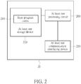
Fig. 2 , thecommunication device 20 may be a communication device or the network shown inFig. 1 , but is not limited herein. Thecommunication device 20 may include at least oneprocessing circuit 200 such as a microprocessor or Application Specific Integrated Circuit (ASIC), at least onestorage device 210 and at least onecommunication interfacing device 220. The at least onestorage device 210 may be any data storage device that may storeprogram codes 214, accessed and executed by the at least oneprocessing circuit 200. Examples of the at least onestorage device 210 include but are not limited to a subscriber identity module (SIM), read-only memory (ROM), flash memory, random-access memory (RAM), hard disk, optical data storage device, nonvolatile storage device, non-transitory computer-readable medium (e.g., tangible media), etc. The at least onecommunication interfacing device 220 includes at least one transceiver and is used to transmit and receive signals (e.g., data, messages and/or packets) according to processing results of the at least oneprocessing circuit 200. - In the following embodiments, a UE is used to represent a communication device in
Fig. 1 , to simplify the illustration of the embodiments. - A
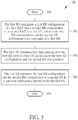
process 30 inFig. 3 according to an example of the present invention may be utilized in a first BS (e.g. in the network inFig. 1 ). Theprocess 30 includes the following steps:Step 300: Start. Step 302: The first BS configures a first radio bearer (RB) configuration of a first radio access technology (RAT) and a second RB configuration of a second RAT to a first UE, wherein the first RB configuration and the second RB configuration are associated to a first RB. Step 304: The first BS communicates data associated to the first RB with the first UE according to the first RB configuration and the second RB configuration. Step 306: The first BS transmits the first RB configuration and the second RB configuration to a second BS in a handover preparation procedure for the first UE. Step 308: End. - According to the
process 30, the second BS communicates data associated to the first RB with the first UE according to the first RB configuration and the second RB configuration, e.g., since the first BS transmits the first RB configuration and the second RB configuration to the second BS in the handover preparation procedure. - In one example, the first BS configures the first RB to the first UE by the first RB configuration and the second RB configuration. In one example, the first RB configuration includes a first RB identity identifying the first RB, and the second RB configuration includes the first RB identity. That is, the first RB configuration and the second RB configuration include the same RB identity (i.e., the first RB identity). The first RB configuration may include the first RB identity and all or at least one of a radio link control (RLC) configuration, a logical channel configuration and a logical channel identity. The RLC configuration, the logical channel configuration and the logical channel identity are associated to the first RB. The second RB configuration may include a packet data convergence protocol (PDCP) configuration. The first/second BS communicates the data associated to the first RB with the first UE according to the PDCP configuration and the all or the at least one of the RLC configuration, the logical channel configuration and the logical channel identity.
- In one example, the first RB configuration does not include a PDCP configuration. In one example, the first RB configuration also includes a PDCP configuration which is different from the PDCP configuration in the second RB configuration. When the first UE receives the PDCP configuration in the first RB configuration and the PDCP configuration in the second RB configuration, the first UE does not use the PDCP configuration in the first RB configuration. The second BS may not use the PDCP configuration in the first RB configuration.
- In one example, the first BS configures the first RB configuration including the PDCP configuration and does not configure the second RB configuration, to a second UE. In one example, the first BS communicates data associated to the first RB with the second UE according to at least one of the RLC configuration, the logical channel configuration and the logical channel identity and the PDCP configuration in the first RB configuration. In one example, the first BS transmits the first RB configuration including the PDCP configuration to the second BS in a handover preparation procedure for the second UE, but does not transmit the second RB configuration in the handover preparation procedure for the second UE. In this case, the second BS may use the at least one of the RLC configuration, the logical channel configuration and the logical channel identity and the PDCP configuration in the first RB configuration to communicate data associated to the first RB with the second UE.
- In one example, in the handover preparation procedure for the first UE via an interface between the first BS and the second BS (e.g., a X2 interface or a Xn interface), the first BS transmits a Handover Request message including the first RB configuration and the second RB configuration to the second BS. The second BS sends a Handover Acknowledge message including a handover command (e.g., radio resource control (RRC) Connection Reconfiguration message) in response to the Handover Request message. In the handover preparation procedure for the first UE via an interface with a network node (e.g., S1 interface), the first BS transmits a Handover Request message including the first RB configuration and the second RB configuration to the network node (e.g., Mobility Management Entity (MME) or Access and Mobility Management Function (AMF)). The network node transmits the first RB configuration and the second RB configuration to the second BS. The network node transmits a Handover Acknowledge message including a handover command (e.g., RRC Connection Reconfiguration message) in response to the Handover Request message. In the above examples, the first BS transmits the handover command to the first UE. The first UE transmits a handover complete (e.g., RRC Connection Reconfiguration Complete message) to the second BS, when connecting to a cell of the second BS according to the handover command. Then, the second BS communicates the data associated to the first RB with the first UE according to the first RB configuration and the second RB configuration. The first UE may perform a random access procedure with the second BS, to transmit the handover complete message.
- In one example, the second BS determines to modify the first RB configuration or the second RB configuration. If the second BS makes the determination, the second BS may include a first modified RB configuration (corresponding to the first RB configuration) or a second modified RB configuration (corresponding to the second RB configuration) in the handover command. The second BS may not modify the first RB identity, and may modify a configuration in the first RB configuration. The second BS may not modify the first RB identity, and may modify a configuration in the second RB configuration.
- In one example, the first RB configuration is a data RB (DRB) configuration (e.g., DRB-ToAddMod information element (IE)) defined in a LTE RRC specification (e.g., 3GPP Technical Specification (TS) 36.331), and the second RB configuration is a DRB configuration (e.g. DRB-ToAddMod IE) defined in a NR RRC specification (e.g., 3GPP TS 38.331 or as shown in the prior art).
- The following is an example of the first DRB configuration.

- The following is an example of the second DRB configuration.

- In one example, the first RB configuration is a signalling RB (SRB) configuration (e.g., SRB-ToAddMod IE) defined in a LTE RRC specification (e.g., 3GPP TS 36.331), and the second RB configuration is a SRB configuration (e.g., SRB-ToAddMod IE) defined in a NR RRC specification (e.g., 3GPP TS 38.331 or as shown in the prior art).
- The following is an example of the first SRB configuration.

- The following is an example of the second SRB configuration.

- In one example, the first BS configures a third RB configuration of the first RAT and a fourth RB configuration of the second RAT to the first UE, wherein the third RB configuration and the fourth RB configuration are associated to a second RB. That is, the first BS configures the second RB to the first UE by the third RB configuration and the fourth RB configuration. The first BS communicates data associated to the second RB with the first UE according to the third RB configuration and the fourth RB configuration. The first BS transmits the third RB configuration and the fourth RB configuration to the second BS, e.g., via the interface between the first BS and the second BS or via the interface with the network node in the handover preparation procedure. The second BS communicates data associated to the second RB with the first UE according to the third RB configuration and the fourth RB configuration. The examples described above for the first RB configuration and the second RB configuration may be applied to the third RB configuration and the fourth RB configuration, respectively, and are not narrated herein.
- In one example, the first RB or the second RB is a SRB or a DRB. The first RAT may be LTE or eLTE (LTE or eLTE may be called evolved universal terrestrial radio access (EUTRA)), and the second RAT may be new radio (NR). The first BS and the second BS may be eNBs. The data may include a plurality of protocol data units (PDUs) such as PDCP PDUs. A PDU may include a RRC message, when the first RB or the second RB is a SRB. A PDU may include a packet of an application (e.g., running in an operating system, e.g., Android, iOS, Windows, Linux, Chrome OS) or an Internet Protocol (IP) packet, when the first RB or the second RB is a DRB.
- In one example, the first RB is a DRB, and the second RB is SRB. In one example, the first RB configuration is a first DRB configuration, and the second RB configuration is a second DRB configuration. In one example, the third RB configuration is a third SRB configuration, and the fourth RB configuration is a fourth SRB configuration. The following is an example of the first DRB configuration (e.g., the DRB-ToAddMod IE in the 3GPP TS 36.331) in a DRB-ToAddModList and the third SRB configuration (e.g., the SRB-ToAddMod IE in the 3GPP TS 36.331) in a SRB-ToAddModList. The DRB-ToAddModList and the SRB-ToAddModList are included in a RadioResourceConfigDedicated of the first RAT. The first BS may transmit the RadioResourceConfigDedicated to the second BS in the handover preparation procedure, e.g. in the Handover Request message described above.

- In one example, the following is an example of the second DRB configuration (e.g., the DRB-ToAddMod IE in the 3GPP TS 38.331) in a DRB-ToAddModList and the fourth SRB configuration (e.g., the SRB-ToAddMod IE in the 3GPP TS 38.331) in a SRB-ToAddModList included in a RadioBearerConfig of the second RAT. The first BS may transmit the RadioBearerConfig to the second BS in the handover preparation procedure, e.g., in the Handover Request message described above.

- In one example, "OPTIONAL" above means that an information element (IE) may or may not exist in the first DRB configuration and/or the second DRB configuration. For example, the first BS may not include a srb-ToReleaseList or a drb-ToReleaseList in a RadioResourceConfigDedicated. If the srb-ToReleaseList (or the drb-ToReleaseList) is included, the second BS may ignore/discard the srb-ToReleaseList (or the drb-ToReleaseList). For example, the first BS may not include the srb-ToReleaseList or the drb-ToReleaseList in the RadioBearerConfig. If the srb-ToReleaseList (or the drb-ToReleaseList) is included, the second BS may ignore/discard the srb-ToReleaseList (or the drb-ToReleaseList). The first BS may not include a securityConfig. If the securityConfig is included, the second BS may ignore/discard the securityConfig.
- In one example, if the first BS does not transmit the second RB configuration and/or the fourth RB configuration together with the first RB configuration and/or the third RB configuration to the second BS in the handover preparation procedure, the second BS may not be able to communicate data associated to the first RB and/or the second RB with the first UE by using the second DRB configuration and/or the fourth DRB configuration. Thus, the present invention solves the issue in the art.
- It should be noted that although the above examples are illustrated to clarify the related operations of corresponding processes. The examples can be combined and/or modified arbitrarily according to system requirements and/or design considerations. Message names and IE names described above are examples and should not narrow a scope of the invention. The first RAT may be NR and the second RAT may be LTE. The first and second BSs may be gNBs.
- Those skilled in the art should readily make combinations, modifications and/or alterations on the abovementioned steps, description and examples. Some steps described above may not necessarily have to be used in the invention. The abovementioned description, steps and/or processes including suggested steps can be realized by means that could be hardware, software, firmware (known as a combination of a hardware device and computer instructions and data that reside as read-only software on the hardware device), an electronic system, or combination thereof. An example of the means may be the
communication device 20. Any of the processes above may be compiled into theprogram codes 214. For the process involving the first BS and/or the second BS, steps performed by the first BS may be compiled into theprogram codes 214 of the first BS and steps performed by the second BS may be compiled into theprogram codes 214 of the second BS. - To sum up, the present invention provides a base station for handling RB configurations of RATs. According to the present invention, a second BS (e.g., a target BS) knows how to communicate data with a UE, after receiving the RB configurations configured to the UE from a first BS (e.g., a source BS).
- Those skilled in the art will readily observe that numerous modifications and alterations of the device and method may be made while retaining the teachings of the invention. Accordingly, the above disclosure should be construed as limited only by the metes and bounds of the appended claims.
Claims (8)
- A first base station, BS, for handling radio bearer, RB, configurations of radio access technologies, RATs, comprising:at least one storage device (210); andat least one processing circuit (200), coupled to the at least one storage device (210), wherein the at least one storage device (210) stores, and the at least one processing circuit (200) is configured to execute, instructions of:configuring (302) a first RB configuration of a first RAT and a second RB configuration of a second RAT to a first communication device, wherein the first RB configuration and the second RB configuration are associated to a first RB;communicating (304) first data associated to the first RB with the first communication device according to the first RB configuration and the second RB configuration; andtransmitting (306) the first RB configuration and the second RB configuration to a second BS in a handover preparation procedure for the first communication device.
- The first BS of claim 1, wherein the first RB configuration comprises a first RB identity identifying the first RB, and the second RB configuration comprises the first RB identity.
- The first BS of claim 2, wherein the first RB configuration comprises at least one of a radio link control, RLC, configuration, a logical channel configuration and a logical channel identity associated to the first RB.
- The first BS of claim 1, wherein the first RB configuration comprises a first packet data convergence protocol, PDCP, configuration which is different from a second PDCP configuration in the second RB configuration.
- The first BS of claim 1, wherein the instructions further comprise:
configuring the first RB configuration comprising a packet data convergence protocol, PDCP, configuration and not configuring the second RB configuration, to a second communication device. - The first BS of claim 5, wherein the instructions further comprise:
communicating second data associated to the first RB with the second communication device according to at least one of a RLC configuration, a logical channel configuration and a logical channel identity in the first RB configuration. - The first BS of claim 5, wherein the instructions further comprise:transmitting the first RB configuration comprising the PDCP configuration to the second BS in a handover preparation procedure for the second communication device; andnot transmitting the second RB configuration in the handover preparation procedure for the second communication device.
- The first BS of claim 1, wherein the instructions further comprise:
transmitting a Handover Request message comprising the first RB configuration and the second RB configuration to the second BS in the handover preparation procedure.
Applications Claiming Priority (1)
| Application Number | Priority Date | Filing Date | Title |
|---|---|---|---|
| US201762578512P | 2017-10-29 | 2017-10-29 |
Publications (2)
| Publication Number | Publication Date |
|---|---|
| EP3477992A1 EP3477992A1 (en) | 2019-05-01 |
| EP3477992B1 true EP3477992B1 (en) | 2020-07-22 |
Family
ID=64082997
Family Applications (1)
| Application Number | Title | Priority Date | Filing Date |
|---|---|---|---|
| EP18203200.3A Active EP3477992B1 (en) | 2017-10-29 | 2018-10-29 | Base station for handling radio bearer configurations of radio access technologies |
Country Status (4)
| Country | Link |
|---|---|
| US (2) | US11337117B2 (en) |
| EP (1) | EP3477992B1 (en) |
| CN (1) | CN109729603B (en) |
| TW (1) | TWI688286B (en) |
Families Citing this family (2)
| Publication number | Priority date | Publication date | Assignee | Title |
|---|---|---|---|---|
| CN114531960B (en) * | 2019-10-03 | 2024-04-26 | Lg电子株式会社 | Method and apparatus for applying target network configuration by user equipment in wireless communication system |
| CN114258151A (en) * | 2020-09-21 | 2022-03-29 | 华为技术有限公司 | Calculation data transmission method and device |
Family Cites Families (28)
| Publication number | Priority date | Publication date | Assignee | Title |
|---|---|---|---|---|
| GB0413484D0 (en) * | 2004-06-16 | 2004-07-21 | Nokia Corp | Inter-mode/inter-rat handover |
| WO2008133476A1 (en) * | 2007-04-30 | 2008-11-06 | Lg Electronics Inc. | Method and procedures for radio bearer setup |
| EP2079253A1 (en) * | 2008-01-09 | 2009-07-15 | Panasonic Corporation | Non-3GPP to 3GPP network handover optimizations |
| US9232452B2 (en) * | 2008-10-31 | 2016-01-05 | Htc Corporation | Method of handling an inter rat handover in wireless communication system and related communication device |
| US8566455B1 (en) * | 2008-12-17 | 2013-10-22 | Marvell International Ltd. | Method and apparatus for supporting multiple connections in 3GPP systems |
| US9398517B2 (en) * | 2010-01-11 | 2016-07-19 | Blackberry Limited | System and method for enabling discovery of local service availability in local cellular coverage |
| BR112012012353A2 (en) * | 2010-02-10 | 2016-03-22 | Research In Motion Ltd | method and apparatus for mode / state transition |
| US8081604B2 (en) * | 2010-02-22 | 2011-12-20 | Htc Corporation | Method and apparatus for handling SRVCC in an inter radio access technology handover |
| US8787172B2 (en) * | 2010-06-21 | 2014-07-22 | Qualcomm Incorporated | Method and apparatus for QoS context transfer during inter radio access technology handover in a wireless communication system |
| WO2012139798A1 (en) * | 2011-04-15 | 2012-10-18 | Telefonaktiebolaget L M Ericsson (Publ) | Methods and devices for radio link monitoring |
| CN103703860B (en) * | 2011-07-29 | 2019-08-16 | 交互数字专利控股公司 | Method and apparatus for the provided for radio resources management in multi radio access technology wireless system |
| EP3570628B1 (en) * | 2011-08-12 | 2020-12-30 | BlackBerry Limited | Handling a connection in a wireless communication system |
| WO2014022970A1 (en) * | 2012-08-07 | 2014-02-13 | 华为技术有限公司 | Handover processing method and enb |
| EP2723134B1 (en) * | 2012-10-18 | 2014-11-26 | Fujitsu Limited | Wireless communication in Multi-RAT System |
| KR101632277B1 (en) * | 2013-03-29 | 2016-07-01 | 주식회사 케이티 | Handover Methods for a mobile station connected with multiple base stations and apparatuses thereof |
| US20150109927A1 (en) * | 2013-10-18 | 2015-04-23 | Qualcomm Incorporated | Base station to access point interface for data bearer routing |
| EP3496495B1 (en) * | 2013-10-31 | 2020-11-25 | Nec Corporation | Radio communication system, base station apparatus, and method |
| US9713044B2 (en) * | 2014-01-30 | 2017-07-18 | Sharp Kabushiki Kaisha | Systems and methods for dual-connectivity operation |
| EP3021612B1 (en) * | 2014-11-12 | 2018-03-21 | HTC Corporation | Device and method of handling network configurations |
| US10271243B2 (en) * | 2015-05-21 | 2019-04-23 | Intel IP Corporation | PDCP status reporting for multi-RAT offloading |
| US10368238B2 (en) * | 2015-12-01 | 2019-07-30 | Htc Corporation | Device and method of handling data transmission/reception for dual connectivity |
| EP3958615A1 (en) * | 2016-08-10 | 2022-02-23 | NEC Corporation | Radio access network node, radio terminal, core network node, and method therefor |
| JP6930540B2 (en) * | 2016-08-10 | 2021-09-01 | 日本電気株式会社 | Radio access network nodes, wireless terminals, core network nodes, and their methods |
| JP6948388B2 (en) * | 2017-02-02 | 2021-10-13 | エルジー エレクトロニクス インコーポレイティドLg Electronics Inc. | Methods and devices for transmitting data units |
| US10349380B2 (en) * | 2017-03-17 | 2019-07-09 | Ofinno, Llc | Radio access network area information |
| CN108924824B (en) * | 2017-03-20 | 2020-10-09 | 电信科学技术研究院 | EPS bearing identifier distribution method and device, SMF and PCF |
| US20180367288A1 (en) * | 2017-06-16 | 2018-12-20 | Huawei Technologies Co., Ltd. | Dynamic activation and deactivation of packet duplication |
| CA3021658A1 (en) * | 2017-10-20 | 2019-04-20 | Comcast Cable Communications, Llc | Non-access stratum capability information |
-
2018
- 2018-10-29 EP EP18203200.3A patent/EP3477992B1/en active Active
- 2018-10-29 CN CN201811270641.3A patent/CN109729603B/en active Active
- 2018-10-29 TW TW107138227A patent/TWI688286B/en active
- 2018-10-29 US US16/172,881 patent/US11337117B2/en active Active
-
2022
- 2022-04-11 US US17/717,161 patent/US20220240130A1/en active Pending
Non-Patent Citations (1)
| Title |
|---|
| None * |
Also Published As
| Publication number | Publication date |
|---|---|
| US11337117B2 (en) | 2022-05-17 |
| TW201918091A (en) | 2019-05-01 |
| US20190132773A1 (en) | 2019-05-02 |
| US20220240130A1 (en) | 2022-07-28 |
| CN109729603A (en) | 2019-05-07 |
| TWI688286B (en) | 2020-03-11 |
| EP3477992A1 (en) | 2019-05-01 |
| CN109729603B (en) | 2020-11-10 |
Similar Documents
| Publication | Publication Date | Title |
|---|---|---|
| US10313934B2 (en) | Device and method of handling communication | |
| EP3413625B1 (en) | Method of handling secondary cell group configuration in secondary node change | |
| EP3355620B1 (en) | Base station and communication device can switch between two different base stations | |
| EP3346760B1 (en) | Devices and methods for handling a new radio connection in inter-system mobility | |
| US10368238B2 (en) | Device and method of handling data transmission/reception for dual connectivity | |
| US10292078B1 (en) | Device and method of handling an evolved packet system bearer context | |
| CN108289314B (en) | Device and method for processing protocol data unit connection in mobility | |
| US10856343B2 (en) | Device and method of handling full configuration | |
| US20220240130A1 (en) | Device and Method of Handling Radio Bearer Configurations of Radio Access Technologies | |
| EP3402308B1 (en) | Coordination between multirat base stations in dual connectivity | |
| EP3399832B1 (en) | Device and method of handling a dual connectivity | |
| EP3355619A1 (en) | Base station and communication device for handover between two base stations | |
| US10624151B2 (en) | Device and method of handling a signalling radio bearer configuration | |
| CN108574993B (en) | Apparatus and method for processing communication in dual connectivity |
Legal Events
| Date | Code | Title | Description |
|---|---|---|---|
| STAA | Information on the status of an ep patent application or granted ep patent |
Free format text: STATUS: EXAMINATION IS IN PROGRESS |
|
| PUAI | Public reference made under article 153(3) epc to a published international application that has entered the european phase |
Free format text: ORIGINAL CODE: 0009012 |
|
| 17P | Request for examination filed |
Effective date: 20181029 |
|
| AK | Designated contracting states |
Kind code of ref document: A1 Designated state(s): AL AT BE BG CH CY CZ DE DK EE ES FI FR GB GR HR HU IE IS IT LI LT LU LV MC MK MT NL NO PL PT RO RS SE SI SK SM TR |
|
| AX | Request for extension of the european patent |
Extension state: BA ME |
|
| RBV | Designated contracting states (corrected) |
Designated state(s): AL AT BE BG CH CY CZ DE DK EE ES FI FR GB GR HR HU IE IS IT LI LT LU LV MC MK MT NL NO PL PT RO RS SE SI SK SM TR |
|
| GRAP | Despatch of communication of intention to grant a patent |
Free format text: ORIGINAL CODE: EPIDOSNIGR1 |
|
| STAA | Information on the status of an ep patent application or granted ep patent |
Free format text: STATUS: GRANT OF PATENT IS INTENDED |
|
| RIC1 | Information provided on ipc code assigned before grant |
Ipc: H04W 36/08 20090101ALN20200109BHEP Ipc: H04W 36/00 20090101AFI20200109BHEP |
|
| INTG | Intention to grant announced |
Effective date: 20200211 |
|
| GRAS | Grant fee paid |
Free format text: ORIGINAL CODE: EPIDOSNIGR3 |
|
| GRAA | (expected) grant |
Free format text: ORIGINAL CODE: 0009210 |
|
| STAA | Information on the status of an ep patent application or granted ep patent |
Free format text: STATUS: THE PATENT HAS BEEN GRANTED |
|
| AK | Designated contracting states |
Kind code of ref document: B1 Designated state(s): AL AT BE BG CH CY CZ DE DK EE ES FI FR GB GR HR HU IE IS IT LI LT LU LV MC MK MT NL NO PL PT RO RS SE SI SK SM TR |
|
| REG | Reference to a national code |
Ref country code: GB Ref legal event code: FG4D |
|
| REG | Reference to a national code |
Ref country code: CH Ref legal event code: EP |
|
| REG | Reference to a national code |
Ref country code: DE Ref legal event code: R096 Ref document number: 602018006228 Country of ref document: DE |
|
| REG | Reference to a national code |
Ref country code: AT Ref legal event code: REF Ref document number: 1294608 Country of ref document: AT Kind code of ref document: T Effective date: 20200815 |
|
| REG | Reference to a national code |
Ref country code: IE Ref legal event code: FG4D |
|
| REG | Reference to a national code |
Ref country code: NL Ref legal event code: FP |
|
| REG | Reference to a national code |
Ref country code: LT Ref legal event code: MG4D |
|
| REG | Reference to a national code |
Ref country code: AT Ref legal event code: MK05 Ref document number: 1294608 Country of ref document: AT Kind code of ref document: T Effective date: 20200722 |
|
| PG25 | Lapsed in a contracting state [announced via postgrant information from national office to epo] |
Ref country code: FI Free format text: LAPSE BECAUSE OF FAILURE TO SUBMIT A TRANSLATION OF THE DESCRIPTION OR TO PAY THE FEE WITHIN THE PRESCRIBED TIME-LIMIT Effective date: 20200722 Ref country code: BG Free format text: LAPSE BECAUSE OF FAILURE TO SUBMIT A TRANSLATION OF THE DESCRIPTION OR TO PAY THE FEE WITHIN THE PRESCRIBED TIME-LIMIT Effective date: 20201022 Ref country code: PT Free format text: LAPSE BECAUSE OF FAILURE TO SUBMIT A TRANSLATION OF THE DESCRIPTION OR TO PAY THE FEE WITHIN THE PRESCRIBED TIME-LIMIT Effective date: 20201123 Ref country code: HR Free format text: LAPSE BECAUSE OF FAILURE TO SUBMIT A TRANSLATION OF THE DESCRIPTION OR TO PAY THE FEE WITHIN THE PRESCRIBED TIME-LIMIT Effective date: 20200722 Ref country code: LT Free format text: LAPSE BECAUSE OF FAILURE TO SUBMIT A TRANSLATION OF THE DESCRIPTION OR TO PAY THE FEE WITHIN THE PRESCRIBED TIME-LIMIT Effective date: 20200722 Ref country code: ES Free format text: LAPSE BECAUSE OF FAILURE TO SUBMIT A TRANSLATION OF THE DESCRIPTION OR TO PAY THE FEE WITHIN THE PRESCRIBED TIME-LIMIT Effective date: 20200722 Ref country code: SE Free format text: LAPSE BECAUSE OF FAILURE TO SUBMIT A TRANSLATION OF THE DESCRIPTION OR TO PAY THE FEE WITHIN THE PRESCRIBED TIME-LIMIT Effective date: 20200722 Ref country code: AT Free format text: LAPSE BECAUSE OF FAILURE TO SUBMIT A TRANSLATION OF THE DESCRIPTION OR TO PAY THE FEE WITHIN THE PRESCRIBED TIME-LIMIT Effective date: 20200722 Ref country code: GR Free format text: LAPSE BECAUSE OF FAILURE TO SUBMIT A TRANSLATION OF THE DESCRIPTION OR TO PAY THE FEE WITHIN THE PRESCRIBED TIME-LIMIT Effective date: 20201023 Ref country code: NO Free format text: LAPSE BECAUSE OF FAILURE TO SUBMIT A TRANSLATION OF THE DESCRIPTION OR TO PAY THE FEE WITHIN THE PRESCRIBED TIME-LIMIT Effective date: 20201022 |
|
| PG25 | Lapsed in a contracting state [announced via postgrant information from national office to epo] |
Ref country code: PL Free format text: LAPSE BECAUSE OF FAILURE TO SUBMIT A TRANSLATION OF THE DESCRIPTION OR TO PAY THE FEE WITHIN THE PRESCRIBED TIME-LIMIT Effective date: 20200722 Ref country code: RS Free format text: LAPSE BECAUSE OF FAILURE TO SUBMIT A TRANSLATION OF THE DESCRIPTION OR TO PAY THE FEE WITHIN THE PRESCRIBED TIME-LIMIT Effective date: 20200722 Ref country code: LV Free format text: LAPSE BECAUSE OF FAILURE TO SUBMIT A TRANSLATION OF THE DESCRIPTION OR TO PAY THE FEE WITHIN THE PRESCRIBED TIME-LIMIT Effective date: 20200722 Ref country code: IS Free format text: LAPSE BECAUSE OF FAILURE TO SUBMIT A TRANSLATION OF THE DESCRIPTION OR TO PAY THE FEE WITHIN THE PRESCRIBED TIME-LIMIT Effective date: 20201122 |
|
| REG | Reference to a national code |
Ref country code: DE Ref legal event code: R097 Ref document number: 602018006228 Country of ref document: DE |
|
| PG25 | Lapsed in a contracting state [announced via postgrant information from national office to epo] |
Ref country code: CZ Free format text: LAPSE BECAUSE OF FAILURE TO SUBMIT A TRANSLATION OF THE DESCRIPTION OR TO PAY THE FEE WITHIN THE PRESCRIBED TIME-LIMIT Effective date: 20200722 Ref country code: DK Free format text: LAPSE BECAUSE OF FAILURE TO SUBMIT A TRANSLATION OF THE DESCRIPTION OR TO PAY THE FEE WITHIN THE PRESCRIBED TIME-LIMIT Effective date: 20200722 Ref country code: RO Free format text: LAPSE BECAUSE OF FAILURE TO SUBMIT A TRANSLATION OF THE DESCRIPTION OR TO PAY THE FEE WITHIN THE PRESCRIBED TIME-LIMIT Effective date: 20200722 Ref country code: EE Free format text: LAPSE BECAUSE OF FAILURE TO SUBMIT A TRANSLATION OF THE DESCRIPTION OR TO PAY THE FEE WITHIN THE PRESCRIBED TIME-LIMIT Effective date: 20200722 Ref country code: SM Free format text: LAPSE BECAUSE OF FAILURE TO SUBMIT A TRANSLATION OF THE DESCRIPTION OR TO PAY THE FEE WITHIN THE PRESCRIBED TIME-LIMIT Effective date: 20200722 Ref country code: IT Free format text: LAPSE BECAUSE OF FAILURE TO SUBMIT A TRANSLATION OF THE DESCRIPTION OR TO PAY THE FEE WITHIN THE PRESCRIBED TIME-LIMIT Effective date: 20200722 |
|
| PLBE | No opposition filed within time limit |
Free format text: ORIGINAL CODE: 0009261 |
|
| STAA | Information on the status of an ep patent application or granted ep patent |
Free format text: STATUS: NO OPPOSITION FILED WITHIN TIME LIMIT |
|
| PG25 | Lapsed in a contracting state [announced via postgrant information from national office to epo] |
Ref country code: AL Free format text: LAPSE BECAUSE OF FAILURE TO SUBMIT A TRANSLATION OF THE DESCRIPTION OR TO PAY THE FEE WITHIN THE PRESCRIBED TIME-LIMIT Effective date: 20200722 |
|
| 26N | No opposition filed |
Effective date: 20210423 |
|
| PG25 | Lapsed in a contracting state [announced via postgrant information from national office to epo] |
Ref country code: LU Free format text: LAPSE BECAUSE OF NON-PAYMENT OF DUE FEES Effective date: 20201029 Ref country code: MC Free format text: LAPSE BECAUSE OF FAILURE TO SUBMIT A TRANSLATION OF THE DESCRIPTION OR TO PAY THE FEE WITHIN THE PRESCRIBED TIME-LIMIT Effective date: 20200722 Ref country code: SK Free format text: LAPSE BECAUSE OF FAILURE TO SUBMIT A TRANSLATION OF THE DESCRIPTION OR TO PAY THE FEE WITHIN THE PRESCRIBED TIME-LIMIT Effective date: 20200722 |
|
| REG | Reference to a national code |
Ref country code: BE Ref legal event code: MM Effective date: 20201031 |
|
| PG25 | Lapsed in a contracting state [announced via postgrant information from national office to epo] |
Ref country code: SI Free format text: LAPSE BECAUSE OF FAILURE TO SUBMIT A TRANSLATION OF THE DESCRIPTION OR TO PAY THE FEE WITHIN THE PRESCRIBED TIME-LIMIT Effective date: 20200722 Ref country code: BE Free format text: LAPSE BECAUSE OF NON-PAYMENT OF DUE FEES Effective date: 20201031 |
|
| PG25 | Lapsed in a contracting state [announced via postgrant information from national office to epo] |
Ref country code: IE Free format text: LAPSE BECAUSE OF NON-PAYMENT OF DUE FEES Effective date: 20201029 |
|
| REG | Reference to a national code |
Ref country code: CH Ref legal event code: PL |
|
| PG25 | Lapsed in a contracting state [announced via postgrant information from national office to epo] |
Ref country code: TR Free format text: LAPSE BECAUSE OF FAILURE TO SUBMIT A TRANSLATION OF THE DESCRIPTION OR TO PAY THE FEE WITHIN THE PRESCRIBED TIME-LIMIT Effective date: 20200722 Ref country code: MT Free format text: LAPSE BECAUSE OF FAILURE TO SUBMIT A TRANSLATION OF THE DESCRIPTION OR TO PAY THE FEE WITHIN THE PRESCRIBED TIME-LIMIT Effective date: 20200722 Ref country code: CY Free format text: LAPSE BECAUSE OF FAILURE TO SUBMIT A TRANSLATION OF THE DESCRIPTION OR TO PAY THE FEE WITHIN THE PRESCRIBED TIME-LIMIT Effective date: 20200722 |
|
| PG25 | Lapsed in a contracting state [announced via postgrant information from national office to epo] |
Ref country code: MK Free format text: LAPSE BECAUSE OF FAILURE TO SUBMIT A TRANSLATION OF THE DESCRIPTION OR TO PAY THE FEE WITHIN THE PRESCRIBED TIME-LIMIT Effective date: 20200722 |
|
| PG25 | Lapsed in a contracting state [announced via postgrant information from national office to epo] |
Ref country code: LI Free format text: LAPSE BECAUSE OF NON-PAYMENT OF DUE FEES Effective date: 20211031 Ref country code: CH Free format text: LAPSE BECAUSE OF NON-PAYMENT OF DUE FEES Effective date: 20211031 |
|
| P01 | Opt-out of the competence of the unified patent court (upc) registered |
Effective date: 20230602 |
|
| PGFP | Annual fee paid to national office [announced via postgrant information from national office to epo] |
Ref country code: NL Payment date: 20230915 Year of fee payment: 6 Ref country code: GB Payment date: 20230907 Year of fee payment: 6 |
|
| PGFP | Annual fee paid to national office [announced via postgrant information from national office to epo] |
Ref country code: FR Payment date: 20230911 Year of fee payment: 6 |
|
| PGFP | Annual fee paid to national office [announced via postgrant information from national office to epo] |
Ref country code: DE Payment date: 20230906 Year of fee payment: 6 |