EP3476146B1 - Preamble based access for an uplink transmission - Google Patents
Preamble based access for an uplink transmission Download PDFInfo
- Publication number
- EP3476146B1 EP3476146B1 EP16910053.4A EP16910053A EP3476146B1 EP 3476146 B1 EP3476146 B1 EP 3476146B1 EP 16910053 A EP16910053 A EP 16910053A EP 3476146 B1 EP3476146 B1 EP 3476146B1
- Authority
- EP
- European Patent Office
- Prior art keywords
- information
- uplink
- preamble sequence
- code
- acknowledgement
- Prior art date
- Legal status (The legal status is an assumption and is not a legal conclusion. Google has not performed a legal analysis and makes no representation as to the accuracy of the status listed.)
- Active
Links
- 230000005540 biological transmission Effects 0.000 title claims description 52
- 238000000034 method Methods 0.000 claims description 51
- 238000013507 mapping Methods 0.000 claims description 6
- 238000004891 communication Methods 0.000 description 41
- 238000010586 diagram Methods 0.000 description 29
- 230000006870 function Effects 0.000 description 9
- 238000012545 processing Methods 0.000 description 9
- 101000741965 Homo sapiens Inactive tyrosine-protein kinase PRAG1 Proteins 0.000 description 8
- 102100038659 Inactive tyrosine-protein kinase PRAG1 Human genes 0.000 description 8
- 230000011664 signaling Effects 0.000 description 4
- 230000003287 optical effect Effects 0.000 description 3
- 238000003491 array Methods 0.000 description 2
- 239000000463 material Substances 0.000 description 2
- 230000010363 phase shift Effects 0.000 description 2
- 230000004044 response Effects 0.000 description 2
- 239000004065 semiconductor Substances 0.000 description 2
- 230000000007 visual effect Effects 0.000 description 2
- 101150039363 SIB2 gene Proteins 0.000 description 1
- 238000009529 body temperature measurement Methods 0.000 description 1
- 230000000694 effects Effects 0.000 description 1
- 238000005516 engineering process Methods 0.000 description 1
- 208000028626 extracranial carotid artery aneurysm Diseases 0.000 description 1
- 230000010354 integration Effects 0.000 description 1
- 230000007774 longterm Effects 0.000 description 1
- 238000004519 manufacturing process Methods 0.000 description 1
- 238000012544 monitoring process Methods 0.000 description 1
- 229920001690 polydopamine Polymers 0.000 description 1
- 230000002441 reversible effect Effects 0.000 description 1
- 239000004984 smart glass Substances 0.000 description 1
- 230000003068 static effect Effects 0.000 description 1
- 230000001360 synchronised effect Effects 0.000 description 1
Images


Classifications
-
- H—ELECTRICITY
- H04—ELECTRIC COMMUNICATION TECHNIQUE
- H04W—WIRELESS COMMUNICATION NETWORKS
- H04W74/00—Wireless channel access, e.g. scheduled or random access
- H04W74/002—Transmission of channel access control information
- H04W74/004—Transmission of channel access control information in the uplink, i.e. towards network
-
- H—ELECTRICITY
- H04—ELECTRIC COMMUNICATION TECHNIQUE
- H04L—TRANSMISSION OF DIGITAL INFORMATION, e.g. TELEGRAPHIC COMMUNICATION
- H04L1/00—Arrangements for detecting or preventing errors in the information received
- H04L1/12—Arrangements for detecting or preventing errors in the information received by using return channel
- H04L1/16—Arrangements for detecting or preventing errors in the information received by using return channel in which the return channel carries supervisory signals, e.g. repetition request signals
- H04L1/18—Automatic repetition systems, e.g. Van Duuren systems
- H04L1/1867—Arrangements specially adapted for the transmitter end
- H04L1/1896—ARQ related signaling
-
- H—ELECTRICITY
- H04—ELECTRIC COMMUNICATION TECHNIQUE
- H04L—TRANSMISSION OF DIGITAL INFORMATION, e.g. TELEGRAPHIC COMMUNICATION
- H04L5/00—Arrangements affording multiple use of the transmission path
- H04L5/003—Arrangements for allocating sub-channels of the transmission path
- H04L5/0053—Allocation of signaling, i.e. of overhead other than pilot signals
- H04L5/0055—Physical resource allocation for ACK/NACK
-
- H—ELECTRICITY
- H04—ELECTRIC COMMUNICATION TECHNIQUE
- H04W—WIRELESS COMMUNICATION NETWORKS
- H04W72/00—Local resource management
- H04W72/04—Wireless resource allocation
- H04W72/044—Wireless resource allocation based on the type of the allocated resource
- H04W72/0466—Wireless resource allocation based on the type of the allocated resource the resource being a scrambling code
-
- H—ELECTRICITY
- H04—ELECTRIC COMMUNICATION TECHNIQUE
- H04L—TRANSMISSION OF DIGITAL INFORMATION, e.g. TELEGRAPHIC COMMUNICATION
- H04L5/00—Arrangements affording multiple use of the transmission path
- H04L5/003—Arrangements for allocating sub-channels of the transmission path
- H04L5/0044—Arrangements for allocating sub-channels of the transmission path allocation of payload
-
- H—ELECTRICITY
- H04—ELECTRIC COMMUNICATION TECHNIQUE
- H04L—TRANSMISSION OF DIGITAL INFORMATION, e.g. TELEGRAPHIC COMMUNICATION
- H04L5/00—Arrangements affording multiple use of the transmission path
- H04L5/003—Arrangements for allocating sub-channels of the transmission path
- H04L5/0053—Allocation of signaling, i.e. of overhead other than pilot signals
-
- H—ELECTRICITY
- H04—ELECTRIC COMMUNICATION TECHNIQUE
- H04W—WIRELESS COMMUNICATION NETWORKS
- H04W4/00—Services specially adapted for wireless communication networks; Facilities therefor
- H04W4/70—Services for machine-to-machine communication [M2M] or machine type communication [MTC]
-
- H—ELECTRICITY
- H04—ELECTRIC COMMUNICATION TECHNIQUE
- H04W—WIRELESS COMMUNICATION NETWORKS
- H04W74/00—Wireless channel access, e.g. scheduled or random access
- H04W74/08—Non-scheduled or contention based access, e.g. random access, ALOHA, CSMA [Carrier Sense Multiple Access]
- H04W74/0833—Non-scheduled or contention based access, e.g. random access, ALOHA, CSMA [Carrier Sense Multiple Access] using a random access procedure
Landscapes
- Engineering & Computer Science (AREA)
- Signal Processing (AREA)
- Computer Networks & Wireless Communication (AREA)
- Mobile Radio Communication Systems (AREA)
Description
- The subject matter disclosed herein relates generally to wireless communications and more particularly relates to a preamble based access for an uplink transmission.
- The following abbreviations are herewith defined, at least some of which are referred to within the following description: Third Generation Partnership Project ("3GPP"), Positive-Acknowledgment ("ACK"), Binary Phase Shift Keying ("BPSK"), Clear Channel Assessment ("CCA"), Cyclic Prefix ("CP"), Channel State Information ("CSI"), Common Search Space ("CSS"), Downlink Control Information ("DCI"), Downlink ("DL"), Downlink Pilot Time Slot ("DwPTS"), Enhanced Clear Channel Assessment ("eCCA"), Evolved Node B ("eNB"), European Telecommunications Standards Institute ("ETSI"), Frame Based Equipment ("FBE"), Frequency Division Duplex ("FDD"), Frequency Division Multiple Access ("FDMA"), Guard Period ("GP"), Hybrid Automatic Repeat Request ("HARQ"), Licensed Assisted Access ("LAA"), Load Based Equipment ("LBE"), Listen-Before-Talk ("LBT"), Long Term Evolution ("LTE"), Negative-Acknowledgment ("NACK") or ("NAK"), Orthogonal Frequency Division Multiplexing ("OFDM"), Primary Cell ("PCell"), Physical Broadcast Channel ("PBCH"), Physical Downlink Control Channel ("PDCCH"), Physical Downlink Shared Channel ("PDSCH"), Physical Hybrid ARQ Indicator Channel ("PHICH"), Physical Random Access Channel ("PRACH"), Physical Resource Block ("PRB"), Physical Uplink Control Channel ("PUCCH"), Physical Uplink Shared Channel ("PUSCH"), Quality of Service ("QoS"), Quadrature Phase Shift Keying ("QPSK"), Radio Resource Control ("RRC"), Random Access Procedure ("RACH"), Round Trip Time ("RTT"), Receive ("RX"), Scheduling Request ("SR"), Single Carrier Frequency Division Multiple Access ("SC-FDMA"), Secondary Cell ("SCell"), Shared Channel ("SCH"), Signal-to-Interference-Plus-Noise Ratio ("SINR"), System Information Block ("SIB"), Transport Block ("TB"), Transport Block Size ("TBS"), Time-Division Duplex ("TDD"), Time Division Multiplex ("TDM"), Transmit ("TX"), Uplink Control Information ("UCI"), User Entity/Equipment (Mobile Terminal) ("UE"), Uplink ("UL"), Universal Mobile Telecommunications System ("UMTS"), Uplink Pilot Time Slot ("UpPTS"), and Worldwide Interoperability for Microwave Access ("WiMAX"). As used herein, "HARQ-ACK" may represent collectively the Positive Acknowledge ("ACK") and the Negative Acknowledge ("NAK"). ACK means that a TB is correctly received while NAK means a TB is erroneously received.
- In certain wireless communications networks, there are two ways to initiate uplink transmission. One way to initiate uplink transmission is by using SR based PUSCH transmission. Another way to initiate uplink transmission is by using RACH based PUSCH transmission. For SR based PUSCH transmission, before a UE transmits uplink data to an eNB, the UE sends a SR if the eNB has configured the SR in RRC. The SR may be transmitted on at least one PUCCH resource. In certain configurations, if the UE receives an UL grant from the eNB after the SR tranmission, a UL-SCH is transmitted according to the UL grant.
- In some configurations, if a UE is not configured with SR information, is in a RRC_IDEL state, or loses synchronization, the UE may start a RACH procedure to obtain a new connection to the network.
- In various configurations, a RACH procedure includes an exchange of four different messages between a UE and an eNB. A first message may include a randomly selected preamble sent in an available resource according to an SIB2 configuration. In a second message, the eNB replies with the random access response ("RAR") to all detected preambles. Step 3: If the second message is received, it includes uplink grant information, pointing to the RB where a third message including a connection request should be sent. Upon reception of the connection request, the eNB transmits a fourth message including a contention resolution message as an answer to the third message.
- Massive machine type communication ("MTC"), such as in wide area sensor networks, mission critical MTC, industrial applications, may be considered important. Existing technologies know as LTE have been designed to support high data rates, particular in the downlink, and high velocities for a small number of UEs per radio cell.
- However, new types of services may have different characteristics and requirements. In a massive MTC scenario, multiple sensor nodes sporadically transmit small uplink data payloads (e.g., temperature measurements). Moreover, an increasing number of applications installed on smart phones generate traffic with similar properties. In the case of LTE, each small data packet comes along with a cascade of signaling messages in both directions for connection setup and request of radio resources. Signaling overhead is a more significant part of over-the-air transmissions for such transmission cases, and a large portion of the device power consumption. So SR based uplink transmission and RACH based uplink transmission may not be suitable for massive MTC scenarios.
-
US 2016/0014723 A1 discloses a data transmission method, user equipment, a base station, and a system. The method includes: selecting, by user equipment, a preamble sequence, and acquiring an uplink time-frequency resource and a downlink time-frequency resource that are corresponding to the preamble sequence; sending the preamble sequence to a base station, so that the base station decodes the preamble sequence, and determines, according to the decoded preamble sequence, the uplink time-frequency resource and the downlink time-frequency resource that are corresponding to the decoded preamble sequence. - The invention is set out in the appended set of claims.
- A more particular description of the embodiments briefly described above will be rendered by reference to specific embodiments that are illustrated in the appended drawings. Understanding that these drawings depict only some embodiments and are not therefore to be considered to be limiting of scope, the embodiments will be described and explained with additional specificity and detail through the use of the accompanying drawings, in which:
-
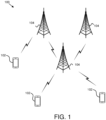
Figure 1 is a schematic block diagram illustrating one embodiment of a wireless communication system for uplink transmissions; -
Figure 2 is a schematic block diagram illustrating one embodiment of an apparatus that may be used for transmitting uplink transmissions; -
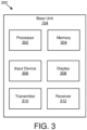
Figure 3 is a schematic block diagram illustrating one embodiment of an apparatus that may be used for receiving uplink transmissions; -
Figure 4 illustrates one embodiment of communications for transmitting uplink transmissions; -
Figure 5 illustrates one embodiment of uplink transmission timing; -
Figure 6 is a schematic block diagram illustrating one embodiment of resource assignment and coding for uplink transmissions; -
Figure 7 is a schematic flow chart diagram illustrating one embodiment of a method for transmitting an uplink transmission; and -
Figure 8 is a schematic flow chart diagram illustrating one embodiment of a method for receiving an uplink transmission. - As will be appreciated by one skilled in the art, aspects of the embodiments may be embodied as an apparatus or method. Accordingly, embodiments may take the form of an entirely hardware embodiment, an entirely software embodiment (including firmware, resident software, micro-code, etc.) or an embodiment combining software and hardware aspects that may all generally be referred to herein as a "circuit," "module" or "system." Furthermore, embodiments may take the form of a program product embodied in one or more computer readable storage devices storing machine readable code, computer readable code, and/or program code, referred hereafter as code. The storage devices may be tangible, non-transitory, and/or non-transmission. The storage devices may not embody signals. In a certain embodiment, the storage devices only employ signals for accessing code.
- Certain of the functional units described in this specification may be labeled as modules, in order to more particularly emphasize their implementation independence. For example, a module may be implemented as a hardware circuit comprising custom very-large-scale integration ("VLSI") circuits or gate arrays, off-the-shelf semiconductors such as logic chips, transistors, or other discrete components. A module may also be implemented in programmable hardware devices such as field programmable gate arrays, programmable array logic, programmable logic devices or the like.
- Modules may also be implemented in code and/or software for execution by various types of processors. An identified module of code may, for instance, include one or more physical or logical blocks of executable code which may, for instance, be organized as an object, procedure, or function. Nevertheless, the executables of an identified module need not be physically located together, but may include disparate instructions stored in different locations which, when joined logically together, include the module and achieve the stated purpose for the module.
- Indeed, a module of code may be a single instruction, or many instructions, and may even be distributed over several different code segments, among different programs, and across several memory devices. Similarly, operational data may be identified and illustrated herein within modules, and may be embodied in any suitable form and organized within any suitable type of data structure. The operational data may be collected as a single data set, or may be distributed over different locations including over different computer readable storage devices. Where a module or portions of a module are implemented in software, the software portions are stored on one or more computer readable storage devices.
- Any combination of one or more computer readable medium may be utilized. The computer readable medium may be a computer readable storage medium. The computer readable storage medium may be a storage device storing the code. The storage device may be, for example, but not limited to, an electronic, magnetic, optical, electromagnetic, infrared, holographic, micromechanical, or semiconductor system, apparatus, or device, or any suitable combination of the foregoing.
- More specific examples (a non-exhaustive list) of the storage device would include the following: an electrical connection having one or more wires, a portable computer diskette, a hard disk, a random access memory ("RAM"), a read-only memory ("ROM"), an erasable programmable read-only memory ("EPROM" or Flash memory), a portable compact disc read-only memory ("CD-ROM"), an optical storage device, a magnetic storage device, or any suitable combination of the foregoing. In the context of this document, a computer readable storage medium may be any tangible medium that can contain, or store a program for use by or in connection with an instruction execution system, apparatus, or device.
- Code for carrying out operations for embodiments may be any number of lines and may be written in any combination of one or more programming languages including an object oriented programming language such as Python, Ruby, Java, Smalltalk, C++, or the like, and conventional procedural programming languages, such as the "C" programming language, or the like, and/or machine languages such as assembly languages. The code may execute entirely on the user's computer, partly on the user's computer, as a stand-alone software package, partly on the user's computer and partly on a remote computer or entirely on the remote computer or server. In the latter scenario, the remote computer may be connected to the user's computer through any type of network, including a local area network ("LAN") or a wide area network ("WAN"), or the connection may be made to an external computer (for example, through the Internet using an Internet Service Provider).
- Reference throughout this specification to "one embodiment," "an embodiment," or similar language means that a particular feature, structure, or characteristic described in connection with the embodiment is included in at least one embodiment. Thus, appearances of the phrases "in one embodiment," "in an embodiment," and similar language throughout this specification may, but do not necessarily, all refer to the same embodiment, but mean "one or more but not all embodiments" unless expressly specified otherwise. The terms "including," "comprising," "having," and variations thereof mean "including but not limited to," unless expressly specified otherwise. An enumerated listing of items does not imply that any or all of the items are mutually exclusive, unless expressly specified otherwise. The terms "a," "an," and "the" also refer to "one or more" unless expressly specified otherwise.
- Furthermore, the described features, structures, or characteristics of the embodiments may be combined in any suitable manner. In the following description, numerous specific details are provided, such as examples of programming, software modules, user selections, network transactions, database queries, database structures, hardware modules, hardware circuits, hardware chips, etc., to provide a thorough understanding of embodiments. One skilled in the relevant art will recognize, however, that embodiments may be practiced without one or more of the specific details, or with other methods, components, materials, and so forth. In other instances, well-known structures, materials, or operations are not shown or described in detail to avoid obscuring aspects of an embodiment.
- Aspects of the embodiments are described below with reference to schematic flowchart diagrams and/or schematic block diagrams of methods, apparatuses, systems, and program products according to embodiments. It will be understood that each block of the schematic flowchart diagrams and/or schematic block diagrams, and combinations of blocks in the schematic flowchart diagrams and/or schematic block diagrams, can be implemented by code. These code may be provided to a processor of a general purpose computer, special purpose computer, or other programmable data processing apparatus to produce a machine, such that the instructions, which execute via the processor of the computer or other programmable data processing apparatus, create means for implementing the functions/acts specified in the schematic flowchart diagrams and/or schematic block diagrams block or blocks.
- The code may also be stored in a storage device that can direct a computer, other programmable data processing apparatus, or other devices to function in a particular manner, such that the instructions stored in the storage device produce an article of manufacture including instructions which implement the function/act specified in the schematic flowchart diagrams and/or schematic block diagrams block or blocks.
- The code may also be loaded onto a computer, other programmable data processing apparatus, or other devices to cause a series of operational steps to be performed on the computer, other programmable apparatus or other devices to produce a computer implemented process such that the code which execute on the computer or other programmable apparatus provide processes for implementing the functions/acts specified in the flowchart and/or block diagram block or blocks.
- The schematic flowchart diagrams and/or schematic block diagrams in the Figures illustrate the architecture, functionality, and operation of possible implementations of apparatuses, systems, methods and program products according to various embodiments. In this regard, each block in the schematic flowchart diagrams and/or schematic block diagrams may represent a module, segment, or portion of code, which includes one or more executable instructions of the code for implementing the specified logical function(s).
- It should also be noted that, in some alternative implementations, the functions noted in the block may occur out of the order noted in the Figures. For example, two blocks shown in succession may, in fact, be executed substantially concurrently, or the blocks may sometimes be executed in the reverse order, depending upon the functionality involved. Other steps and methods may be conceived that are equivalent in function, logic, or effect to one or more blocks, or portions thereof, of the illustrated Figures.
- Although various arrow types and line types may be employed in the flowchart and/or block diagrams, they are understood not to limit the scope of the corresponding embodiments. Indeed, some arrows or other connectors may be used to indicate only the logical flow of the depicted embodiment. For instance, an arrow may indicate a waiting or monitoring period of unspecified duration between enumerated steps of the depicted embodiment. It will also be noted that each block of the block diagrams and/or flowchart diagrams, and combinations of blocks in the block diagrams and/or flowchart diagrams, can be implemented by special purpose hardware-based systems that perform the specified functions or acts, or combinations of special purpose hardware and code.
- The description of elements in each figure may refer to elements of proceeding figures. Like numbers refer to like elements in all figures, including alternate embodiments of like elements.
-
Figure 1 depicts an embodiment of awireless communication system 100 for uplink transmissions. In one embodiment, thewireless communication system 100 includesremote units 102 andbase units 104. Even though a specific number ofremote units 102 andbase units 104 are depicted inFigure 1 , one of skill in the art will recognize that any number ofremote units 102 andbase units 104 may be included in thewireless communication system 100. - In one embodiment, the
remote units 102 may include computing devices, such as desktop computers, laptop computers, personal digital assistants ("PDAs"), tablet computers, smart phones, smart televisions (e.g., televisions connected to the Internet), set-top boxes, game consoles, security systems (including security cameras), vehicle on-board computers, network devices (e.g., routers, switches, modems), or the like. In some embodiments, theremote units 102 include wearable devices, such as smart watches, fitness bands, optical head-mounted displays, or the like. Moreover, theremote units 102 may be referred to as subscriber units, mobiles, mobile stations, users, terminals, mobile terminals, fixed terminals, subscriber stations, UE, user terminals, a device, or by other terminology used in the art. Theremote units 102 may communicate directly with one or more of thebase units 104 via UL communication signals. - The
base units 104 may be distributed over a geographic region. In certain embodiments, abase unit 104 may also be referred to as an access point, an access terminal, a base, a base station, a Node-B, an eNB, a Home Node-B, a relay node, a device, or by any other terminology used in the art. Thebase units 104 are generally part of a radio access network that includes one or more controllers communicably coupled to one or morecorresponding base units 104. The radio access network is generally communicably coupled to one or more core networks, which may be coupled to other networks, like the Internet and public switched telephone networks, among other networks. These and other elements of radio access and core networks are not illustrated but are well known generally by those having ordinary skill in the art. - In one implementation, the
wireless communication system 100 is compliant with the LTE of the 3GPP protocol, wherein thebase unit 104 transmits using an OFDM modulation scheme on the DL and theremote units 102 transmit on the UL using a SC-FDMA scheme. More generally, however, thewireless communication system 100 may implement some other open or proprietary communication protocol, for example, WiMAX, among other protocols. The present disclosure is not intended to be limited to the implementation of any particular wireless communication system architecture or protocol. - The
base units 104 may serve a number ofremote units 102 within a serving area, for example, a cell or a cell sector via a wireless communication link. Thebase units 104 transmit DL communication signals to serve theremote units 102 in the time, frequency, and/or spatial domain. - In one embodiment, a
remote unit 102 generates a preamble sequence for an uplink transmission. The preamble sequence includes indication information. Theremote unit 102 transmits the preamble sequence. Theremote unit 102 also transmits uplink information based on the indication information. Accordingly, aremote unit 102 transmits uplink transmissions. - In another embodiment, a
base unit 104 may receive a preamble sequence. The preamble sequence is for an uplink transmission and includes indication information. In some embodiments, thebase unit 104 receives uplink information based on the indication information. Accordingly, abase unit 104 receives uplink transmissions. -
Figure 2 depicts one embodiment of anapparatus 200 that may be used for transmitting uplink transmissions. Theapparatus 200 includes one embodiment of theremote unit 102. Furthermore, theremote unit 102 may include aprocessor 202, amemory 204, aninput device 206, adisplay 208, atransmitter 210, and areceiver 212. In some embodiments, theinput device 206 and thedisplay 208 are combined into a single device, such as a touchscreen. In certain embodiments, theremote unit 102 may not include anyinput device 206 and/ordisplay 208. In various embodiments, theremote unit 102 may include one or more of theprocessor 202, thememory 204, thetransmitter 210, and thereceiver 212, and may not include theinput device 206 and/or thedisplay 208. - The
processor 202, in one embodiment, may include any known controller capable of executing computer-readable instructions and/or capable of performing logical operations. For example, theprocessor 202 may be a microcontroller, a microprocessor, a central processing unit ("CPU"), a graphics processing unit ("GPU"), an auxiliary processing unit, a field programmable gate array ("FPGA"), or similar programmable controller. In some embodiments, theprocessor 202 executes instructions stored in thememory 204 to perform the methods and routines described herein. Theprocessor 202 is communicatively coupled to thememory 204, theinput device 206, thedisplay 208, thetransmitter 210, and thereceiver 212. In certain embodiments, theprocessor 202 may generating a preamble sequence for an uplink transmission. The preamble sequence may include indication information. - The
memory 204, in one embodiment, is a computer readable storage medium. In some embodiments, thememory 204 includes volatile computer storage media. For example, thememory 204 may include a RAM, including dynamic RAM ("DRAM"), synchronous dynamic RAM ("SDRAM"), and/or static RAM ("SRAM"). In some embodiments, thememory 204 includes non-volatile computer storage media. For example, thememory 204 may include a hard disk drive, a flash memory, or any other suitable non-volatile computer storage device. In some embodiments, thememory 204 includes both volatile and non-volatile computer storage media. In some embodiments, thememory 204 stores data relating to an indication to be provided to another device. In some embodiments, thememory 204 also stores program code and related data, such as an operating system or other controller algorithms operating on theremote unit 102. - The
input device 206, in one embodiment, may include any known computer input device including a touch panel, a button, a keyboard, a stylus, a microphone, or the like. In some embodiments, theinput device 206 may be integrated with thedisplay 208, for example, as a touchscreen or similar touch-sensitive display. In some embodiments, theinput device 206 includes a touchscreen such that text may be input using a virtual keyboard displayed on the touchscreen and/or by handwriting on the touchscreen. In some embodiments, theinput device 206 includes two or more different devices, such as a keyboard and a touch panel. - The
display 208, in one embodiment, may include any known electronically controllable display or display device. Thedisplay 208 may be designed to output visual, audible, and/or haptic signals. In some embodiments, thedisplay 208 includes an electronic display capable of outputting visual data to a user. For example, thedisplay 208 may include, but is not limited to, an LCD display, an LED display, an OLED display, a projector, or similar display device capable of outputting images, text, or the like to a user. As another, non-limiting, example, thedisplay 208 may include a wearable display such as a smart watch, smart glasses, a heads-up display, or the like. Further, thedisplay 208 may be a component of a smart phone, a personal digital assistant, a television, a table computer, a notebook (laptop) computer, a personal computer, a vehicle dashboard, or the like. - In certain embodiments, the
display 208 includes one or more speakers for producing sound. For example, thedisplay 208 may produce an audible alert or notification (e.g., a beep or chime). In some embodiments, thedisplay 208 includes one or more haptic devices for producing vibrations, motion, or other haptic feedback. In some embodiments, all or portions of thedisplay 208 may be integrated with theinput device 206. For example, theinput device 206 anddisplay 208 may form a touchscreen or similar touch-sensitive display. In other embodiments, thedisplay 208 may be located near theinput device 206. - The
transmitter 210 is used to provide UL communication signals to thebase unit 104 and thereceiver 212 is used to receive DL communication signals from thebase unit 104. In one embodiment, thetransmitter 210 is used to transmit a preamble sequence, and to transmit uplink information based on indication information of the preamble sequence. In certain embodiments, thereceiver 212 may be used to receive data. Although only onetransmitter 210 and onereceiver 212 are illustrated, theremote unit 102 may have any suitable number oftransmitters 210 andreceivers 212. Thetransmitter 210 and thereceiver 212 may be any suitable type of transmitters and receivers. In one embodiment, thetransmitter 210 and thereceiver 212 may be part of a transceiver. -
Figure 3 depicts one embodiment of anapparatus 300 that may be used for receiving uplink transmissions. Theapparatus 300 includes one embodiment of thebase unit 104. Furthermore, thebase unit 104 may include aprocessor 302, amemory 304, aninput device 306, adisplay 308, atransmitter 310, and areceiver 312. As may be appreciated, theprocessor 302, thememory 304, theinput device 306, and thedisplay 308 may be substantially similar to theprocessor 202, thememory 204, theinput device 206, and thedisplay 208 of theremote unit 102, respectively. - The
receiver 312 is used to receive a preamble sequence. The preamble sequence is for an uplink transmission and includes indication information. Thereceiver 312 is also used to receive uplink information based on the indication information. Although only onetransmitter 310 and onereceiver 312 are illustrated, thebase unit 104 may have any suitable number oftransmitters 310 andreceivers 312. Thetransmitter 310 and thereceiver 312 may be any suitable type of transmitters and receivers. In one embodiment, thetransmitter 310 and thereceiver 312 may be part of a transceiver. -
Figure 4 illustrates one embodiment ofcommunications 400 for transmitting uplink transmissions. Specifically,communications 400 between aUE 402 and aneNB 404 are illustrated. Afirst communication 406 includes RRC configuration transmitted from theeNB 404 and received by theUE 402. In some embodiments, the RRC configures an access occasion, a preamble sequence, uplink grant information configuration, a relationship, and/or a multiple access ("MA") code. - In certain embodiments, the preamble sequence configured by the RRC may be a RACH preamble sequence. In various embodiments, there may be 64 different RACH preamble sequences available, while in some embodiments, there may be fewer or greater than 64 different RACH preamble sequences. In some embodiments, the RACH preamble sequences may be Zadoff-Chu sequences. In one embodiment, the preamble sequence configured by the RRC may be an M sequence plus a Zadoff-Chu sequence to support a large number of UEs. In certain embodiments, if preamble sequences would affect legacy systems, other sequences may be used such as a new Zadoff-Chu sequence with a different length. In some embodiments, only one sequence with different time-frequency transmission is assumed to be a different preamble sequence.
- In various embodiments, the uplink grant information configured by the RRC may be linked with the preamble sequence by code, time, and/or frequency. In some embodiments, the uplink grant information may include information indicating a transmission resource assignment, a new data indicator, a transmit power control command, a modulation and coding scheme reference signal, configuration information, an acknowledgement and non-acknowledgement resource assignment, a multiple access code, and/or a scrambled code. The information may be indicated explicitly in the preamble sequence and/or the information may be indicated implicitly by the preamble sequence, such as by a predetermined mapping between the preamble sequence and the uplink grant information. In some embodiments, a mapping between a preamble sequence and uplink grant information may be determined by dynamic signaling configuration, pre-configuration, and/or by being predetermined, such as in a specification. In certain embodiments, the multiple access code may be indicated by the preamble sequence if code based non-orthogonal access is used in uplink transmissions.
- A
second communication 408 includes the preamble sequence being transmitted from the UE 402 (e.g., remote unit 102) and received by the eNB 404 (e.g., base unit 104). In various embodiments, theUE 402 may randomly select one preamble sequence and transmit the preamble sequence in the predefined access occasion as predefined by the RRC configuration. In some embodiments, the preamble sequence may be used for timing and/or frequency synchronization. - A
third communication 410 includes uplink information. In certain embodiments, the uplink information includes control information and/or data information. In one embodiment, without a response to thesecond communication 408 by theeNB 404, theUE 402 transmits the uplink information. In various embodiments, the uplink information is transmitted in the uplink resource indicated by the preamble sequence and/or with the multiple access code indicated by the preamble sequence. In some embodiments, the uplink information is transmitted with a combined or a separated coded packet in the same or different uplink resource based on indication information of the preamble sequence. In certain embodiments, the uplink information may be scrambled based on indication information of the preamble sequence. For example, an index corresponding the preamble sequence may be used to initialize a bit sequence and the uplink information may be scrambled using the bit sequence. - In one embodiment, control information of the uplink information includes a UE identification ("ID"), a buffer status report, and a hybrid automatic repeat request process number. In certain embodiments, control information is not transmitted from the
UE 402, but is indicated, predefined, preconfigured, or determined another way. In some embodiments, such as if theUE 402 has a cell radio network temporary identifier ("C-RNTI"), a UE ID may be the C-RNTI. In various embodiments, such as if theUE 402 does not have a C-RNTI, a UE ID may be a random ID, an implicitly indicated ID, or an explicitly indicated ID. In one embodiment, the preamble sequence and the uplink information may be transmitted in the same transmission time interval ("TTI") and/or subframe. For example, in a single subframe, the preamble sequence may be transmitted followed closely by the uplink information. - A
fourth communication 412 includes an acknowledgement ("ACK") or non-acknowledgement ("NACK") transmitted from theeNB 404 to theUE 402 to indicate ACK/NACK of the uplink information. In certain embodiments, theUE 402 may wait to receive the ACK/NACK information, or wait for a timer to expire and start a new RACH procedure. In some embodiments, the ACK/NACK may be transmitted in a predefined resource or transmitted in a resource indicated by the preamble sequence. In various embodiments, the ACK/NACK may be transmitted in a downlink control channel, PHICH, among others. In various embodiments, if theUE 402 does not receive the ACK/NACK without a predetermined time period, a new access procedure may be started. - By performing transmissions as described herein (e.g., with a grant-free based uplink transmission) may improve connection efficiency, reduce signaling overhead, and/or latency reduction that may be used for massive MTC and/or critical MTC.
-
Figure 5 illustrates one embodiment ofuplink transmission timing 500. Specifically,multiple communications 502 are illustrated. In one embodiment, thecommunications 502 may be equated with one or more subframes. Furthermore,multiple access possibilities 504 are illustrated among themultiple communications 502. Moreover, in some embodiments, afirst communication 506 is transmitted from thebase unit 104 to theremote unit 102 and includes RRC configuration. Thefirst communication 506 may be substantially similar to thefirst communication 406. - In certain embodiments, a
second communication 508 is transmitted from theremote unit 102 to thebase unit 104 and includes a preamble sequence. Thesecond communication 508 may be substantially similar to thesecond communication 408. In various embodiments, athird communication 510 is transmitted from theremote unit 102 to thebase unit 104 and includes uplink information. As illustrated, thethird communication 510 may be transmitted over multiple of thecommunications 502. Thethird communication 510 may be substantially similar to thethird communication 410. In some embodiments, afourth communication 512 is transmitted from thebase unit 104 to theremote unit 102 and includes an ACK/NACK. Thefourth communication 512 may be substantially similar to thefourth communication 412. -
Figure 6 is a schematic block diagram illustrating one embodiment of resource assignment andcoding 600 for uplink transmissions. Specifically, afirst preamble 602, a second preamble 604, athird preamble 606, afourth preamble 608, afifth preamble 610, and asixth preamble 612 are illustrated. The first andsecond preambles 602 and 604 may use afirst resource 614, the third andfourth preambles second resource 616, and the fifth andsixth preambles third resource 618. To distinguish between the different preambles transmitted using a same resource, afirst MA code 620 and asecond MA code 622 are used. Specifically, the first, third, andfifth preambles first MA code 620. Moreover, the second, fourth, andsixth preambles second MA code 622. The resources and MA codes may be allocated as set forth above inFigure 4 . -
Figure 7 is a schematic flow chart diagram illustrating one embodiment of amethod 700 for transmitting an uplink transmission. In some embodiments, themethod 700 is performed by an apparatus, such as theremote unit 102. In certain embodiments, themethod 700 may be performed by a processor executing program code, for example, a microcontroller, a microprocessor, a CPU, a GPU, an auxiliary processing unit, a FPGA, or the like. - The
method 700 may include generating 702 a preamble sequence for an uplink transmission. The preamble sequence may include indication information. In some embodiments, the indication information indicates one or more of a transmission resource assignment, a new data indicator, a transmit power control command, a modulation and coding scheme reference signal, configuration information, an acknowledgement and non-acknowledgement resource assignment, a multiple access code, and a scrambled code. In such an embodiment, the apparatus includes a receiver that receives acknowledgement or non-acknowledgement feedback information corresponding to the transmission of the uplink information. In certain embodiments, the uplink information is transmitted using the multiple access code. In some embodiments, the uplink information is scrambled by the scrambled code. - The
method 700 may also include transmitting 704 the preamble sequence. Themethod 700 may include transmitting 706 uplink information based on the indication information, and themethod 700 may end. In one embodiment, the uplink information includes one or more of control information and data information. In such an embodiment, the control information includes one or more of a remote unit identification, a buffer status report, and a hybrid automatic repeat request process number. In a further embodiment, a mapping relationship between the preamble sequence and the indication information is predefined (e.g., via specification, preconfigured) or received from an external device (e.g., base unit 104). -
Figure 8 is a schematic flow chart diagram illustrating one embodiment of amethod 800 for receiving an uplink transmission. In some embodiments, themethod 800 is performed by an apparatus, such as thebase unit 104. In certain embodiments, themethod 800 may be performed by a processor executing program code, for example, a microcontroller, a microprocessor, a CPU, a GPU, an auxiliary processing unit, a FPGA, or the like. - The
method 800 may include receiving 802 a preamble sequence. The preamble sequence may be for an uplink transmission and may include indication information. In some embodiments, the indication information indicates one or more of a transmission resource assignment, a new data indicator, a transmit power control command, a modulation and coding scheme reference signal, configuration information, an acknowledgement and non-acknowledgement resource assignment, a multiple access code, and a scrambled code. In such an embodiment, the apparatus includes a transmitter that transmits acknowledgement or non-acknowledgement feedback information corresponding to the reception of the uplink information. In certain embodiments, the uplink information is received using the multiple access code. In some embodiments, the uplink information is scrambled by the scrambled code. - In various embodiments, the
method 800 includes receiving 804 uplink information based on the indication information, and themethod 800 may end. In one embodiment, the uplink information includes one or more of control information and data information. In such an embodiment, the control information includes one or more of a remote unit identification, a buffer status report, and a hybrid automatic repeat request process number. In a further embodiment, a mapping relationship between the preamble sequence and the indication information is predefined (e.g., via specification, preconfigured) or transmitted from the apparatus (e.g., base unit 104). - Embodiments may be practiced in other specific forms. The described embodiments are to be considered in all respects only as illustrative and not restrictive. The scope of the invention is, therefore, indicated by the appended claims rather than by the foregoing description.
Claims (13)
- A method performed by a remote unit (102), comprising:generating (702) a preamble sequence to establish a random access channel procedure for an uplink transmission, wherein the preamble sequence comprises indication information;transmitting (704) the preamble sequence; andtransmitting (706) uplink information separate from the preamble sequence and based on the indication information in the preamble sequence; wherein the uplink information comprises control information, wherein the indication information indicates one or more of a transmission resource assignment, a new data indicator, a transmit power control command, a modulation and coding scheme reference signal, configuration information, an acknowledgement and non-acknowledgement resource assignment, a multiple access code, and a scrambled code; and wherein the control information comprises one or more of a remote unit identification, a buffer status report, and a hybrid automatic repeat request process number.
- The method of claim 1, wherein the uplink information further comprises data information.
- The method of claim 1, wherein a mapping relationship between the preamble sequence and the indication information is predefined or received from a base unit (104).
- The method of claim 1, further comprising receiving acknowledgement or non-acknowledgement feedback information corresponding to the transmission of the uplink information.
- The method of claim 1, wherein the uplink information is transmitted using the multiple access code.
- The method of claim 1, wherein the uplink information is scrambled by the scrambled code.
- A method performed by a base unit (104), comprising:receiving (802) a preamble sequence to establish a random access channel procedure for an uplink transmission, the preamble sequence comprising indication information; andreceiving (804) uplink information separate from the preamble sequence and based on the indication information in the preamble sequence; wherein the uplink information comprises control information;wherein the indication information indicates one or more of a transmission resource assignment, a new data indicator, a transmit power control command, a modulation and coding scheme reference signal, configuration information, an acknowledgement and non-acknowledgement resource assignment, a multiple access code, and a scrambled code; and wherein the control information comprises one or more of a remote unit identification, a buffer status report, and a hybrid automatic repeat request process number.
- The method of claim 7, wherein the uplink information further comprises data information.
- The method of claim 7, wherein a mapping relationship between the preamble sequence and the indication information is predefined.
- The method of claim 7, further comprising transmitting acknowledgement or non-acknowledgement feedback information corresponding to the reception of the uplink information.
- The method of claim 7, wherein:the uplink information is received using the multiple access code; and/orthe uplink information is scrambled by the scrambled code.
- A remote unit (102) comprising means for performing the method of any of claims 1 to 6.
- A base unit (104) comprising means for performing the method of any of claims 7 to 11.
Applications Claiming Priority (1)
| Application Number | Priority Date | Filing Date | Title |
|---|---|---|---|
| PCT/CN2016/091953 WO2018018472A1 (en) | 2016-07-27 | 2016-07-27 | Preamble based access for an uplink transmission |
Publications (3)
| Publication Number | Publication Date |
|---|---|
| EP3476146A1 EP3476146A1 (en) | 2019-05-01 |
| EP3476146A4 EP3476146A4 (en) | 2020-02-12 |
| EP3476146B1 true EP3476146B1 (en) | 2024-03-20 |
Family
ID=61015355
Family Applications (1)
| Application Number | Title | Priority Date | Filing Date |
|---|---|---|---|
| EP16910053.4A Active EP3476146B1 (en) | 2016-07-27 | 2016-07-27 | Preamble based access for an uplink transmission |
Country Status (4)
| Country | Link |
|---|---|
| US (1) | US11812463B2 (en) |
| EP (1) | EP3476146B1 (en) |
| CN (1) | CN109479192A (en) |
| WO (1) | WO2018018472A1 (en) |
Families Citing this family (3)
| Publication number | Priority date | Publication date | Assignee | Title |
|---|---|---|---|---|
| US11304146B2 (en) * | 2017-08-03 | 2022-04-12 | Lg Electronics Inc. | Method for controlling transmission power in wireless communication system, and apparatus therefor |
| US20210352700A1 (en) * | 2018-11-01 | 2021-11-11 | Lenovo (Beijing) Limited | A buffer status report indicator |
| WO2021031039A1 (en) * | 2019-08-16 | 2021-02-25 | 华为技术有限公司 | Method and apparatus for sending random access message |
Family Cites Families (21)
| Publication number | Priority date | Publication date | Assignee | Title |
|---|---|---|---|---|
| US7406261B2 (en) * | 1999-11-02 | 2008-07-29 | Lot 41 Acquisition Foundation, Llc | Unified multi-carrier framework for multiple-access technologies |
| US7079507B2 (en) * | 2000-02-25 | 2006-07-18 | Nokia Corporation | Method and apparatus for common packet channel assignment |
| KR100567211B1 (en) * | 2003-12-11 | 2006-04-03 | 한국전자통신연구원 | System and method for transmitting random access data of orthogonal frequency division multiplexing-frequency division multiple access |
| US7587660B2 (en) * | 2005-04-22 | 2009-09-08 | Kansas State University Research Foundation | Multiple-access code generation |
| CN101346906B (en) * | 2005-12-23 | 2013-10-16 | Lg电子株式会社 | Random access procedure processing method |
| US8054796B2 (en) * | 2006-12-08 | 2011-11-08 | Nokia Corporation | Uplink acknowledgment channel in wireless communication |
| JP4580035B2 (en) * | 2007-08-17 | 2010-11-10 | 株式会社エヌ・ティ・ティ・ドコモ | Mobile communication method, radio base station apparatus and mobile station |
| JP5278642B2 (en) * | 2007-10-02 | 2013-09-04 | 日本電気株式会社 | Common channel resource allocation method and apparatus |
| US8681701B2 (en) * | 2010-06-03 | 2014-03-25 | Via Telecom Co., Ltd. | Mobile communications devices and transmission methods for transmitting machine type communication data thereof |
| CN103535102B (en) * | 2011-05-05 | 2017-06-20 | 瑞典爱立信有限公司 | For adapting to the method and apparatus that resource is distributed to the Stochastic accessing of user equipment |
| EP2751946A1 (en) * | 2012-01-25 | 2014-07-09 | Fujitsu Limited | Uplink channel for wireless communication |
| CN107509199B (en) * | 2012-05-10 | 2020-10-20 | 三星电子株式会社 | Method for data message transmission by user equipment in wireless cellular network |
| KR101589911B1 (en) * | 2012-08-03 | 2016-02-18 | 주식회사 케이티 | Methods and apparatuses for power control of random access |
| US20140192767A1 (en) * | 2012-12-14 | 2014-07-10 | Futurewei Technologies, Inc. | System and Method for Small Traffic Transmissions |
| WO2014146300A1 (en) * | 2013-03-22 | 2014-09-25 | 华为技术有限公司 | Data transmission method, user equipment, base station, and system |
| CN104254135B (en) * | 2013-06-27 | 2020-03-31 | 夏普株式会社 | Base station and user equipment and method thereof |
| US10034308B2 (en) * | 2014-03-11 | 2018-07-24 | Lg Electronics Inc. | Method for allocating temporary identifier to terminal in random access procedure in wireless communication system and apparatus therefor |
| US20150282185A1 (en) * | 2014-03-28 | 2015-10-01 | Futurewei Technologies, Inc. | Multi-user, multiple access, systems, methods, and devices |
| CN104981022B (en) * | 2014-04-04 | 2020-07-10 | 北京三星通信技术研究有限公司 | Data transmission method, base station and terminal |
| US10932297B2 (en) * | 2016-04-05 | 2021-02-23 | Sony Corporation | Wireless telecommunications apparatus and methods |
| CN109644494B (en) * | 2016-06-15 | 2022-08-12 | 康维达无线有限责任公司 | Device for random access process in next generation network |
-
2016
- 2016-07-27 CN CN201680087494.9A patent/CN109479192A/en active Pending
- 2016-07-27 EP EP16910053.4A patent/EP3476146B1/en active Active
- 2016-07-27 US US16/321,421 patent/US11812463B2/en active Active
- 2016-07-27 WO PCT/CN2016/091953 patent/WO2018018472A1/en unknown
Also Published As
| Publication number | Publication date |
|---|---|
| EP3476146A4 (en) | 2020-02-12 |
| US20210282175A1 (en) | 2021-09-09 |
| US11812463B2 (en) | 2023-11-07 |
| WO2018018472A1 (en) | 2018-02-01 |
| CN109479192A (en) | 2019-03-15 |
| EP3476146A1 (en) | 2019-05-01 |
Similar Documents
| Publication | Publication Date | Title |
|---|---|---|
| WO2018145037A1 (en) | Configuration information for an inactive state | |
| US11432322B2 (en) | Resource configuration priority levels | |
| WO2018175444A1 (en) | Feedback for a system information request | |
| EP4080980B1 (en) | Scheduling request indication | |
| EP3695672B1 (en) | Determining a transmission scheme | |
| US11595958B2 (en) | Determining a beam for preamble transmission | |
| US20220046636A1 (en) | Resource reservation | |
| US20210212024A1 (en) | Device-to-device transmission | |
| US20210099268A1 (en) | Feedback message transmission for one or more processes | |
| US20190182834A1 (en) | Timing advance adjustment communication | |
| EP3476146B1 (en) | Preamble based access for an uplink transmission | |
| US11317365B2 (en) | Apparatuses and methods for determining time delay | |
| WO2018200989A1 (en) | Determining to transition to a connected state | |
| US11283582B2 (en) | Uplink transmission blanking |
Legal Events
| Date | Code | Title | Description |
|---|---|---|---|
| STAA | Information on the status of an ep patent application or granted ep patent |
Free format text: STATUS: THE INTERNATIONAL PUBLICATION HAS BEEN MADE |
|
| PUAI | Public reference made under article 153(3) epc to a published international application that has entered the european phase |
Free format text: ORIGINAL CODE: 0009012 |
|
| STAA | Information on the status of an ep patent application or granted ep patent |
Free format text: STATUS: REQUEST FOR EXAMINATION WAS MADE |
|
| STAA | Information on the status of an ep patent application or granted ep patent |
Free format text: STATUS: REQUEST FOR EXAMINATION WAS MADE |
|
| 17P | Request for examination filed |
Effective date: 20190125 |
|
| AK | Designated contracting states |
Kind code of ref document: A1 Designated state(s): AL AT BE BG CH CY CZ DE DK EE ES FI FR GB GR HR HU IE IS IT LI LT LU LV MC MK MT NL NO PL PT RO RS SE SI SK SM TR |
|
| AX | Request for extension of the european patent |
Extension state: BA ME |
|
| DAV | Request for validation of the european patent (deleted) | ||
| DAX | Request for extension of the european patent (deleted) | ||
| A4 | Supplementary search report drawn up and despatched |
Effective date: 20200113 |
|
| RIC1 | Information provided on ipc code assigned before grant |
Ipc: H04W 74/00 20090101AFI20200107BHEP Ipc: H04L 5/00 20060101ALI20200107BHEP Ipc: H04L 1/18 20060101ALN20200107BHEP |
|
| STAA | Information on the status of an ep patent application or granted ep patent |
Free format text: STATUS: EXAMINATION IS IN PROGRESS |
|
| STAA | Information on the status of an ep patent application or granted ep patent |
Free format text: STATUS: EXAMINATION IS IN PROGRESS |
|
| 17Q | First examination report despatched |
Effective date: 20210901 |
|
| REG | Reference to a national code |
Ref document number: 602016086480 Country of ref document: DE Ref country code: DE Ref legal event code: R079 Free format text: PREVIOUS MAIN CLASS: H04W0008240000 Ipc: H04W0074000000 |
|
| GRAP | Despatch of communication of intention to grant a patent |
Free format text: ORIGINAL CODE: EPIDOSNIGR1 |
|
| STAA | Information on the status of an ep patent application or granted ep patent |
Free format text: STATUS: GRANT OF PATENT IS INTENDED |
|
| RIC1 | Information provided on ipc code assigned before grant |
Ipc: H04W 74/08 20090101ALN20230509BHEP Ipc: H04L 1/1867 20230101ALI20230509BHEP Ipc: H04L 5/00 20060101ALI20230509BHEP Ipc: H04W 74/00 20090101AFI20230509BHEP |
|
| INTG | Intention to grant announced |
Effective date: 20230523 |
|
| GRAJ | Information related to disapproval of communication of intention to grant by the applicant or resumption of examination proceedings by the epo deleted |
Free format text: ORIGINAL CODE: EPIDOSDIGR1 |
|
| STAA | Information on the status of an ep patent application or granted ep patent |
Free format text: STATUS: EXAMINATION IS IN PROGRESS |
|
| GRAP | Despatch of communication of intention to grant a patent |
Free format text: ORIGINAL CODE: EPIDOSNIGR1 |
|
| STAA | Information on the status of an ep patent application or granted ep patent |
Free format text: STATUS: GRANT OF PATENT IS INTENDED |
|
| INTC | Intention to grant announced (deleted) | ||
| RIC1 | Information provided on ipc code assigned before grant |
Ipc: H04W 4/70 20180101ALN20231002BHEP Ipc: H04W 74/08 20090101ALN20231002BHEP Ipc: H04L 1/1867 20230101ALI20231002BHEP Ipc: H04L 5/00 20060101ALI20231002BHEP Ipc: H04W 74/00 20090101AFI20231002BHEP |
|
| INTG | Intention to grant announced |
Effective date: 20231016 |
|
| GRAS | Grant fee paid |
Free format text: ORIGINAL CODE: EPIDOSNIGR3 |
|
| GRAA | (expected) grant |
Free format text: ORIGINAL CODE: 0009210 |
|
| STAA | Information on the status of an ep patent application or granted ep patent |
Free format text: STATUS: THE PATENT HAS BEEN GRANTED |
|
| AK | Designated contracting states |
Kind code of ref document: B1 Designated state(s): AL AT BE BG CH CY CZ DE DK EE ES FI FR GB GR HR HU IE IS IT LI LT LU LV MC MK MT NL NO PL PT RO RS SE SI SK SM TR |
|
| REG | Reference to a national code |
Ref country code: GB Ref legal event code: FG4D |
|
| REG | Reference to a national code |
Ref country code: CH Ref legal event code: EP |
|
| REG | Reference to a national code |
Ref country code: DE Ref legal event code: R096 Ref document number: 602016086480 Country of ref document: DE |