EP3475543B1 - Method and device for the exhaust gas aftertreatment of an internal combustion engine - Google Patents
Method and device for the exhaust gas aftertreatment of an internal combustion engine Download PDFInfo
- Publication number
- EP3475543B1 EP3475543B1 EP17731538.9A EP17731538A EP3475543B1 EP 3475543 B1 EP3475543 B1 EP 3475543B1 EP 17731538 A EP17731538 A EP 17731538A EP 3475543 B1 EP3475543 B1 EP 3475543B1
- Authority
- EP
- European Patent Office
- Prior art keywords
- particle filter
- secondary air
- exhaust
- regeneration
- temperature
- Prior art date
- Legal status (The legal status is an assumption and is not a legal conclusion. Google has not performed a legal analysis and makes no representation as to the accuracy of the status listed.)
- Active
Links
- 238000002485 combustion reaction Methods 0.000 title claims description 88
- 238000000034 method Methods 0.000 title claims description 41
- 239000002245 particle Substances 0.000 claims description 165
- 238000011069 regeneration method Methods 0.000 claims description 71
- 230000008929 regeneration Effects 0.000 claims description 70
- 230000003197 catalytic effect Effects 0.000 claims description 31
- 239000004071 soot Substances 0.000 claims description 31
- 238000011144 upstream manufacturing Methods 0.000 claims description 23
- 239000000203 mixture Substances 0.000 claims description 15
- 239000000523 sample Substances 0.000 claims description 15
- 238000010438 heat treatment Methods 0.000 claims description 13
- 238000011068 loading method Methods 0.000 claims description 13
- 230000000717 retained effect Effects 0.000 claims description 13
- 239000000446 fuel Substances 0.000 claims description 6
- 230000008859 change Effects 0.000 claims description 3
- 230000001419 dependent effect Effects 0.000 claims description 2
- 230000000977 initiatory effect Effects 0.000 claims description 2
- 230000001172 regenerating effect Effects 0.000 claims description 2
- 230000000750 progressive effect Effects 0.000 claims 1
- 239000007789 gas Substances 0.000 description 59
- QVGXLLKOCUKJST-UHFFFAOYSA-N atomic oxygen Chemical compound [O] QVGXLLKOCUKJST-UHFFFAOYSA-N 0.000 description 17
- 239000001301 oxygen Substances 0.000 description 17
- 229910052760 oxygen Inorganic materials 0.000 description 17
- 230000003647 oxidation Effects 0.000 description 15
- 238000007254 oxidation reaction Methods 0.000 description 15
- MWUXSHHQAYIFBG-UHFFFAOYSA-N nitrogen oxide Inorganic materials O=[N] MWUXSHHQAYIFBG-UHFFFAOYSA-N 0.000 description 9
- 238000006243 chemical reaction Methods 0.000 description 5
- 229930195733 hydrocarbon Natural products 0.000 description 4
- 150000002430 hydrocarbons Chemical class 0.000 description 4
- 230000001105 regulatory effect Effects 0.000 description 4
- UGFAIRIUMAVXCW-UHFFFAOYSA-N Carbon monoxide Chemical compound [O+]#[C-] UGFAIRIUMAVXCW-UHFFFAOYSA-N 0.000 description 3
- 230000033228 biological regulation Effects 0.000 description 3
- 238000009530 blood pressure measurement Methods 0.000 description 3
- 229910002091 carbon monoxide Inorganic materials 0.000 description 3
- 239000011248 coating agent Substances 0.000 description 3
- 238000000576 coating method Methods 0.000 description 3
- 239000003344 environmental pollutant Substances 0.000 description 3
- 230000006872 improvement Effects 0.000 description 3
- 231100000719 pollutant Toxicity 0.000 description 3
- 230000003685 thermal hair damage Effects 0.000 description 3
- 239000000470 constituent Substances 0.000 description 2
- 230000001276 controlling effect Effects 0.000 description 2
- 230000006378 damage Effects 0.000 description 2
- 238000011161 development Methods 0.000 description 2
- 230000018109 developmental process Effects 0.000 description 2
- 239000001257 hydrogen Substances 0.000 description 2
- 229910052739 hydrogen Inorganic materials 0.000 description 2
- 230000008569 process Effects 0.000 description 2
- UFHFLCQGNIYNRP-UHFFFAOYSA-N Hydrogen Chemical compound [H][H] UFHFLCQGNIYNRP-UHFFFAOYSA-N 0.000 description 1
- 206010053615 Thermal burn Diseases 0.000 description 1
- 230000008901 benefit Effects 0.000 description 1
- 238000007664 blowing Methods 0.000 description 1
- 239000003054 catalyst Substances 0.000 description 1
- 239000003638 chemical reducing agent Substances 0.000 description 1
- 238000004140 cleaning Methods 0.000 description 1
- 238000010924 continuous production Methods 0.000 description 1
- 230000003247 decreasing effect Effects 0.000 description 1
- 230000000694 effects Effects 0.000 description 1
- 150000002431 hydrogen Chemical class 0.000 description 1
- 238000002156 mixing Methods 0.000 description 1
- 238000013021 overheating Methods 0.000 description 1
- 230000036632 reaction speed Effects 0.000 description 1
- 230000004044 response Effects 0.000 description 1
Images


Classifications
-
- F—MECHANICAL ENGINEERING; LIGHTING; HEATING; WEAPONS; BLASTING
- F01—MACHINES OR ENGINES IN GENERAL; ENGINE PLANTS IN GENERAL; STEAM ENGINES
- F01N—GAS-FLOW SILENCERS OR EXHAUST APPARATUS FOR MACHINES OR ENGINES IN GENERAL; GAS-FLOW SILENCERS OR EXHAUST APPARATUS FOR INTERNAL COMBUSTION ENGINES
- F01N11/00—Monitoring or diagnostic devices for exhaust-gas treatment apparatus, e.g. for catalytic activity
- F01N11/002—Monitoring or diagnostic devices for exhaust-gas treatment apparatus, e.g. for catalytic activity the diagnostic devices measuring or estimating temperature or pressure in, or downstream of the exhaust apparatus
-
- F—MECHANICAL ENGINEERING; LIGHTING; HEATING; WEAPONS; BLASTING
- F01—MACHINES OR ENGINES IN GENERAL; ENGINE PLANTS IN GENERAL; STEAM ENGINES
- F01N—GAS-FLOW SILENCERS OR EXHAUST APPARATUS FOR MACHINES OR ENGINES IN GENERAL; GAS-FLOW SILENCERS OR EXHAUST APPARATUS FOR INTERNAL COMBUSTION ENGINES
- F01N3/00—Exhaust or silencing apparatus having means for purifying, rendering innocuous, or otherwise treating exhaust
- F01N3/02—Exhaust or silencing apparatus having means for purifying, rendering innocuous, or otherwise treating exhaust for cooling, or for removing solid constituents of, exhaust
- F01N3/021—Exhaust or silencing apparatus having means for purifying, rendering innocuous, or otherwise treating exhaust for cooling, or for removing solid constituents of, exhaust by means of filters
-
- F—MECHANICAL ENGINEERING; LIGHTING; HEATING; WEAPONS; BLASTING
- F01—MACHINES OR ENGINES IN GENERAL; ENGINE PLANTS IN GENERAL; STEAM ENGINES
- F01N—GAS-FLOW SILENCERS OR EXHAUST APPARATUS FOR MACHINES OR ENGINES IN GENERAL; GAS-FLOW SILENCERS OR EXHAUST APPARATUS FOR INTERNAL COMBUSTION ENGINES
- F01N3/00—Exhaust or silencing apparatus having means for purifying, rendering innocuous, or otherwise treating exhaust
- F01N3/08—Exhaust or silencing apparatus having means for purifying, rendering innocuous, or otherwise treating exhaust for rendering innocuous
- F01N3/10—Exhaust or silencing apparatus having means for purifying, rendering innocuous, or otherwise treating exhaust for rendering innocuous by thermal or catalytic conversion of noxious components of exhaust
- F01N3/101—Three-way catalysts
-
- F—MECHANICAL ENGINEERING; LIGHTING; HEATING; WEAPONS; BLASTING
- F01—MACHINES OR ENGINES IN GENERAL; ENGINE PLANTS IN GENERAL; STEAM ENGINES
- F01N—GAS-FLOW SILENCERS OR EXHAUST APPARATUS FOR MACHINES OR ENGINES IN GENERAL; GAS-FLOW SILENCERS OR EXHAUST APPARATUS FOR INTERNAL COMBUSTION ENGINES
- F01N3/00—Exhaust or silencing apparatus having means for purifying, rendering innocuous, or otherwise treating exhaust
- F01N3/08—Exhaust or silencing apparatus having means for purifying, rendering innocuous, or otherwise treating exhaust for rendering innocuous
- F01N3/10—Exhaust or silencing apparatus having means for purifying, rendering innocuous, or otherwise treating exhaust for rendering innocuous by thermal or catalytic conversion of noxious components of exhaust
- F01N3/18—Exhaust or silencing apparatus having means for purifying, rendering innocuous, or otherwise treating exhaust for rendering innocuous by thermal or catalytic conversion of noxious components of exhaust characterised by methods of operation; Control
- F01N3/20—Exhaust or silencing apparatus having means for purifying, rendering innocuous, or otherwise treating exhaust for rendering innocuous by thermal or catalytic conversion of noxious components of exhaust characterised by methods of operation; Control specially adapted for catalytic conversion ; Methods of operation or control of catalytic converters
- F01N3/2006—Periodically heating or cooling catalytic reactors, e.g. at cold starting or overheating
-
- F—MECHANICAL ENGINEERING; LIGHTING; HEATING; WEAPONS; BLASTING
- F01—MACHINES OR ENGINES IN GENERAL; ENGINE PLANTS IN GENERAL; STEAM ENGINES
- F01N—GAS-FLOW SILENCERS OR EXHAUST APPARATUS FOR MACHINES OR ENGINES IN GENERAL; GAS-FLOW SILENCERS OR EXHAUST APPARATUS FOR INTERNAL COMBUSTION ENGINES
- F01N3/00—Exhaust or silencing apparatus having means for purifying, rendering innocuous, or otherwise treating exhaust
- F01N3/08—Exhaust or silencing apparatus having means for purifying, rendering innocuous, or otherwise treating exhaust for rendering innocuous
- F01N3/10—Exhaust or silencing apparatus having means for purifying, rendering innocuous, or otherwise treating exhaust for rendering innocuous by thermal or catalytic conversion of noxious components of exhaust
- F01N3/18—Exhaust or silencing apparatus having means for purifying, rendering innocuous, or otherwise treating exhaust for rendering innocuous by thermal or catalytic conversion of noxious components of exhaust characterised by methods of operation; Control
- F01N3/22—Control of additional air supply only, e.g. using by-passes or variable air pump drives
- F01N3/225—Electric control of additional air supply
-
- F—MECHANICAL ENGINEERING; LIGHTING; HEATING; WEAPONS; BLASTING
- F01—MACHINES OR ENGINES IN GENERAL; ENGINE PLANTS IN GENERAL; STEAM ENGINES
- F01N—GAS-FLOW SILENCERS OR EXHAUST APPARATUS FOR MACHINES OR ENGINES IN GENERAL; GAS-FLOW SILENCERS OR EXHAUST APPARATUS FOR INTERNAL COMBUSTION ENGINES
- F01N9/00—Electrical control of exhaust gas treating apparatus
- F01N9/002—Electrical control of exhaust gas treating apparatus of filter regeneration, e.g. detection of clogging
-
- F—MECHANICAL ENGINEERING; LIGHTING; HEATING; WEAPONS; BLASTING
- F01—MACHINES OR ENGINES IN GENERAL; ENGINE PLANTS IN GENERAL; STEAM ENGINES
- F01N—GAS-FLOW SILENCERS OR EXHAUST APPARATUS FOR MACHINES OR ENGINES IN GENERAL; GAS-FLOW SILENCERS OR EXHAUST APPARATUS FOR INTERNAL COMBUSTION ENGINES
- F01N2430/00—Influencing exhaust purification, e.g. starting of catalytic reaction, filter regeneration, or the like, by controlling engine operating characteristics
- F01N2430/06—Influencing exhaust purification, e.g. starting of catalytic reaction, filter regeneration, or the like, by controlling engine operating characteristics by varying fuel-air ratio, e.g. by enriching fuel-air mixture
-
- F—MECHANICAL ENGINEERING; LIGHTING; HEATING; WEAPONS; BLASTING
- F01—MACHINES OR ENGINES IN GENERAL; ENGINE PLANTS IN GENERAL; STEAM ENGINES
- F01N—GAS-FLOW SILENCERS OR EXHAUST APPARATUS FOR MACHINES OR ENGINES IN GENERAL; GAS-FLOW SILENCERS OR EXHAUST APPARATUS FOR INTERNAL COMBUSTION ENGINES
- F01N2550/00—Monitoring or diagnosing the deterioration of exhaust systems
- F01N2550/14—Systems for adding secondary air into exhaust
-
- F—MECHANICAL ENGINEERING; LIGHTING; HEATING; WEAPONS; BLASTING
- F01—MACHINES OR ENGINES IN GENERAL; ENGINE PLANTS IN GENERAL; STEAM ENGINES
- F01N—GAS-FLOW SILENCERS OR EXHAUST APPARATUS FOR MACHINES OR ENGINES IN GENERAL; GAS-FLOW SILENCERS OR EXHAUST APPARATUS FOR INTERNAL COMBUSTION ENGINES
- F01N2560/00—Exhaust systems with means for detecting or measuring exhaust gas components or characteristics
- F01N2560/02—Exhaust systems with means for detecting or measuring exhaust gas components or characteristics the means being an exhaust gas sensor
- F01N2560/025—Exhaust systems with means for detecting or measuring exhaust gas components or characteristics the means being an exhaust gas sensor for measuring or detecting O2, e.g. lambda sensors
-
- F—MECHANICAL ENGINEERING; LIGHTING; HEATING; WEAPONS; BLASTING
- F01—MACHINES OR ENGINES IN GENERAL; ENGINE PLANTS IN GENERAL; STEAM ENGINES
- F01N—GAS-FLOW SILENCERS OR EXHAUST APPARATUS FOR MACHINES OR ENGINES IN GENERAL; GAS-FLOW SILENCERS OR EXHAUST APPARATUS FOR INTERNAL COMBUSTION ENGINES
- F01N2560/00—Exhaust systems with means for detecting or measuring exhaust gas components or characteristics
- F01N2560/05—Exhaust systems with means for detecting or measuring exhaust gas components or characteristics the means being a particulate sensor
-
- F—MECHANICAL ENGINEERING; LIGHTING; HEATING; WEAPONS; BLASTING
- F01—MACHINES OR ENGINES IN GENERAL; ENGINE PLANTS IN GENERAL; STEAM ENGINES
- F01N—GAS-FLOW SILENCERS OR EXHAUST APPARATUS FOR MACHINES OR ENGINES IN GENERAL; GAS-FLOW SILENCERS OR EXHAUST APPARATUS FOR INTERNAL COMBUSTION ENGINES
- F01N2560/00—Exhaust systems with means for detecting or measuring exhaust gas components or characteristics
- F01N2560/06—Exhaust systems with means for detecting or measuring exhaust gas components or characteristics the means being a temperature sensor
-
- F—MECHANICAL ENGINEERING; LIGHTING; HEATING; WEAPONS; BLASTING
- F01—MACHINES OR ENGINES IN GENERAL; ENGINE PLANTS IN GENERAL; STEAM ENGINES
- F01N—GAS-FLOW SILENCERS OR EXHAUST APPARATUS FOR MACHINES OR ENGINES IN GENERAL; GAS-FLOW SILENCERS OR EXHAUST APPARATUS FOR INTERNAL COMBUSTION ENGINES
- F01N2560/00—Exhaust systems with means for detecting or measuring exhaust gas components or characteristics
- F01N2560/07—Exhaust systems with means for detecting or measuring exhaust gas components or characteristics the means being an exhaust gas flow rate or velocity meter or sensor, intake flow meters only when exclusively used to determine exhaust gas parameters
-
- F—MECHANICAL ENGINEERING; LIGHTING; HEATING; WEAPONS; BLASTING
- F01—MACHINES OR ENGINES IN GENERAL; ENGINE PLANTS IN GENERAL; STEAM ENGINES
- F01N—GAS-FLOW SILENCERS OR EXHAUST APPARATUS FOR MACHINES OR ENGINES IN GENERAL; GAS-FLOW SILENCERS OR EXHAUST APPARATUS FOR INTERNAL COMBUSTION ENGINES
- F01N2610/00—Adding substances to exhaust gases
- F01N2610/08—Adding substances to exhaust gases with prior mixing of the substances with a gas, e.g. air
- F01N2610/085—Controlling the air supply
-
- F—MECHANICAL ENGINEERING; LIGHTING; HEATING; WEAPONS; BLASTING
- F01—MACHINES OR ENGINES IN GENERAL; ENGINE PLANTS IN GENERAL; STEAM ENGINES
- F01N—GAS-FLOW SILENCERS OR EXHAUST APPARATUS FOR MACHINES OR ENGINES IN GENERAL; GAS-FLOW SILENCERS OR EXHAUST APPARATUS FOR INTERNAL COMBUSTION ENGINES
- F01N2900/00—Details of electrical control or of the monitoring of the exhaust gas treating apparatus
- F01N2900/04—Methods of control or diagnosing
- F01N2900/0408—Methods of control or diagnosing using a feed-back loop
-
- F—MECHANICAL ENGINEERING; LIGHTING; HEATING; WEAPONS; BLASTING
- F01—MACHINES OR ENGINES IN GENERAL; ENGINE PLANTS IN GENERAL; STEAM ENGINES
- F01N—GAS-FLOW SILENCERS OR EXHAUST APPARATUS FOR MACHINES OR ENGINES IN GENERAL; GAS-FLOW SILENCERS OR EXHAUST APPARATUS FOR INTERNAL COMBUSTION ENGINES
- F01N2900/00—Details of electrical control or of the monitoring of the exhaust gas treating apparatus
- F01N2900/04—Methods of control or diagnosing
- F01N2900/0416—Methods of control or diagnosing using the state of a sensor, e.g. of an exhaust gas sensor
-
- F—MECHANICAL ENGINEERING; LIGHTING; HEATING; WEAPONS; BLASTING
- F01—MACHINES OR ENGINES IN GENERAL; ENGINE PLANTS IN GENERAL; STEAM ENGINES
- F01N—GAS-FLOW SILENCERS OR EXHAUST APPARATUS FOR MACHINES OR ENGINES IN GENERAL; GAS-FLOW SILENCERS OR EXHAUST APPARATUS FOR INTERNAL COMBUSTION ENGINES
- F01N2900/00—Details of electrical control or of the monitoring of the exhaust gas treating apparatus
- F01N2900/06—Parameters used for exhaust control or diagnosing
- F01N2900/14—Parameters used for exhaust control or diagnosing said parameters being related to the exhaust gas
- F01N2900/1402—Exhaust gas composition
-
- F—MECHANICAL ENGINEERING; LIGHTING; HEATING; WEAPONS; BLASTING
- F01—MACHINES OR ENGINES IN GENERAL; ENGINE PLANTS IN GENERAL; STEAM ENGINES
- F01N—GAS-FLOW SILENCERS OR EXHAUST APPARATUS FOR MACHINES OR ENGINES IN GENERAL; GAS-FLOW SILENCERS OR EXHAUST APPARATUS FOR INTERNAL COMBUSTION ENGINES
- F01N2900/00—Details of electrical control or of the monitoring of the exhaust gas treating apparatus
- F01N2900/06—Parameters used for exhaust control or diagnosing
- F01N2900/14—Parameters used for exhaust control or diagnosing said parameters being related to the exhaust gas
- F01N2900/1404—Exhaust gas temperature
-
- F—MECHANICAL ENGINEERING; LIGHTING; HEATING; WEAPONS; BLASTING
- F01—MACHINES OR ENGINES IN GENERAL; ENGINE PLANTS IN GENERAL; STEAM ENGINES
- F01N—GAS-FLOW SILENCERS OR EXHAUST APPARATUS FOR MACHINES OR ENGINES IN GENERAL; GAS-FLOW SILENCERS OR EXHAUST APPARATUS FOR INTERNAL COMBUSTION ENGINES
- F01N2900/00—Details of electrical control or of the monitoring of the exhaust gas treating apparatus
- F01N2900/06—Parameters used for exhaust control or diagnosing
- F01N2900/16—Parameters used for exhaust control or diagnosing said parameters being related to the exhaust apparatus, e.g. particulate filter or catalyst
- F01N2900/1602—Temperature of exhaust gas apparatus
-
- F—MECHANICAL ENGINEERING; LIGHTING; HEATING; WEAPONS; BLASTING
- F01—MACHINES OR ENGINES IN GENERAL; ENGINE PLANTS IN GENERAL; STEAM ENGINES
- F01N—GAS-FLOW SILENCERS OR EXHAUST APPARATUS FOR MACHINES OR ENGINES IN GENERAL; GAS-FLOW SILENCERS OR EXHAUST APPARATUS FOR INTERNAL COMBUSTION ENGINES
- F01N2900/00—Details of electrical control or of the monitoring of the exhaust gas treating apparatus
- F01N2900/06—Parameters used for exhaust control or diagnosing
- F01N2900/16—Parameters used for exhaust control or diagnosing said parameters being related to the exhaust apparatus, e.g. particulate filter or catalyst
- F01N2900/1606—Particle filter loading or soot amount
-
- G—PHYSICS
- G01—MEASURING; TESTING
- G01M—TESTING STATIC OR DYNAMIC BALANCE OF MACHINES OR STRUCTURES; TESTING OF STRUCTURES OR APPARATUS, NOT OTHERWISE PROVIDED FOR
- G01M15/00—Testing of engines
- G01M15/04—Testing internal-combustion engines
- G01M15/10—Testing internal-combustion engines by monitoring exhaust gases or combustion flame
- G01M15/102—Testing internal-combustion engines by monitoring exhaust gases or combustion flame by monitoring exhaust gases
- G01M15/104—Testing internal-combustion engines by monitoring exhaust gases or combustion flame by monitoring exhaust gases using oxygen or lambda-sensors
-
- Y—GENERAL TAGGING OF NEW TECHNOLOGICAL DEVELOPMENTS; GENERAL TAGGING OF CROSS-SECTIONAL TECHNOLOGIES SPANNING OVER SEVERAL SECTIONS OF THE IPC; TECHNICAL SUBJECTS COVERED BY FORMER USPC CROSS-REFERENCE ART COLLECTIONS [XRACs] AND DIGESTS
- Y02—TECHNOLOGIES OR APPLICATIONS FOR MITIGATION OR ADAPTATION AGAINST CLIMATE CHANGE
- Y02T—CLIMATE CHANGE MITIGATION TECHNOLOGIES RELATED TO TRANSPORTATION
- Y02T10/00—Road transport of goods or passengers
- Y02T10/10—Internal combustion engine [ICE] based vehicles
- Y02T10/12—Improving ICE efficiencies
-
- Y—GENERAL TAGGING OF NEW TECHNOLOGICAL DEVELOPMENTS; GENERAL TAGGING OF CROSS-SECTIONAL TECHNOLOGIES SPANNING OVER SEVERAL SECTIONS OF THE IPC; TECHNICAL SUBJECTS COVERED BY FORMER USPC CROSS-REFERENCE ART COLLECTIONS [XRACs] AND DIGESTS
- Y02—TECHNOLOGIES OR APPLICATIONS FOR MITIGATION OR ADAPTATION AGAINST CLIMATE CHANGE
- Y02T—CLIMATE CHANGE MITIGATION TECHNOLOGIES RELATED TO TRANSPORTATION
- Y02T10/00—Road transport of goods or passengers
- Y02T10/10—Internal combustion engine [ICE] based vehicles
- Y02T10/40—Engine management systems
Definitions
- the invention relates to a method and a device for exhaust gas aftertreatment of an internal combustion engine.
- the soot stored in the particle filter can be oxidized.
- measures may include, for example, temporarily adjusting the lean-burn engine of the gasoline engine or blowing secondary air into the exhaust system.
- a lean-burn adjustment of the gasoline engine has been preferred, since this method does not require any additional components and can supply a sufficient amount of oxygen in most operating points of the gasoline engine.
- a complex sensor system is also required to monitor and control the regeneration.
- a disadvantage of such a lean adjustment is that the regeneration temperature required for the regeneration of the particle filter is not reached, especially when the vehicle is operating at low partial load and on short journeys.
- nitrogen oxides cannot be adequately converted by the three-way catalytic converter during lean engine adjustment, since there is no reducing agent for the nitrogen oxides.
- a method for exhaust gas aftertreatment of an internal combustion engine in which the internal combustion engine is operated with a stoichiometric combustion air during the regeneration of the particle filter and secondary air is blown into the exhaust gas duct for the regeneration of the particle filter.
- the secondary air volume is introduced into the exhaust duct via a passive flap valve, so that quantitative control of the secondary air volume is not possible.
- a method for determining the loading of a particle filter in the exhaust gas duct of an internal combustion engine is known, secondary air being introduced into the exhaust gas duct upstream of the particle filter in operating states of the internal combustion engine with small exhaust gas volumes in order to increase the volume flow and thus to improve the result of a differential pressure measurement, from which a Loading state of the particle filter is calculated.
- a method for the regeneration of a particle filter in the exhaust duct of an internal combustion engine wherein the heating of the particle filter is carried out by engine measures of the internal combustion engine and the particle filter is supplied by the residual oxygen of a lean combustion mixture of the internal combustion engine with that for the oxidation of the soot particles retained therein, the Regulation of the residual oxygen quantity for the oxidation of the soot on the particle filter is carried out by the lambda control of the internal combustion engine.
- the DE 10 2010 046 747 A1 discloses a method for exhaust gas aftertreatment of an internal combustion engine with an exhaust gas duct and a three-way catalytic converter arranged in the exhaust gas duct, a particle filter arranged downstream of the three-way catalytic converter, and a secondary air supply.
- the internal combustion engine is operated with a stoichiometric combustion air ratio and at the same time secondary air is blown into the exhaust gas duct in order to provide the oxygen necessary for the oxidation of the soot retained in the particle filter.
- a method for exhaust gas aftertreatment of an internal combustion engine is known, a particle filter with a catalytically active coating being arranged in the exhaust system, secondary air being able to be introduced into the exhaust system upstream of the particle filter.
- a method for the regeneration of a particle filter in an exhaust system of an internal combustion engine is known, the particle filter being arranged in the exhaust system downstream of a three-way catalytic converter.
- a cylinder of the internal combustion engine is operated in the unfired mode in order to provide the oxygen required for the oxidation of the particle filter.
- the DE 10 2010 046 751 A1 discloses a method for regenerating a particulate filter in the exhaust system of an internal combustion engine. Fresh air is compressed by the compressor of an exhaust gas turbocharger and introduced into the exhaust system upstream of the particle filter. Oxygen can be controlled in part by adjusting boost pressure in response to a state of particulate filter regeneration. Furthermore, the raw nitrogen oxide emissions of the internal combustion engine can be controlled by adjusting the exhaust gas recirculation rate.
- the invention is based on the object of providing a method and a device with which both a sufficiently high temperature level for a regeneration of the particle filter is achieved and also during the regeneration of the particle filter the pollutant emissions are kept as low as possible, so that the regeneration of the particle filter in Can be made essentially emission-neutral.
- the particle filter can be heated to a regeneration temperature even at low partial load or in short-distance operation and then regenerated.
- the lambda control can prevent too much oxygen from entering the exhaust gas duct, which can lead to uncontrolled burning of the soot and the associated thermal damage to the particle filter.
- the use of the lambda probe instead of pressure and / or temperature sensors has the advantage that the mixture quality upstream of the particle filter in the exhaust gas duct can be assessed directly.
- a stoichiometric mixture air ratio in the exhaust gas duct downstream of the three-way catalytic converter and upstream of the particle filter is set in the heating phase by introducing the secondary air. This allows the amount of secondary air to be adjusted in such a way that during the heating phase of the particle filter the unburned fuel components are completely converted in the exhaust duct and / or on the particle filter with the oxygen from the secondary air supply, so that there is no decrease in emissions of carbon monoxide ( CO) and unburned hydrocarbons (HC) comes.
- CO carbon monoxide
- HC unburned hydrocarbons
- a temperature of the particle filter is determined and the temperature is kept above the regeneration temperature of the particle filter in the regeneration phase.
- the particle filter can be regenerated in a continuous process until the complete soot load on the particle filter is oxidized. This avoids residual loading of the particle filter, which leads to more frequent regeneration cycles and, as a result, to an increased consumption of the internal combustion engine.
- the introduction of secondary air is stopped when an upper threshold temperature of the particle filter is reached.
- the amount of secondary air metered into the exhaust gas duct is increased or reduced as a function of a change in temperature of the particle filter. If the particle filter temperature rises during regeneration of the particle filter, the amount of secondary air is throttled until the temperature rise has ended. If the particle filter temperature drops, the amount of secondary air is increased during the regeneration in order to increase the soot conversion due to oxidation on the particle filter and, through this exothermic reaction, to stabilize or increase the temperature of the particle filter so that the temperature of the particle filter does not drop below the regeneration temperature during the regeneration sinks and no further soot particles can be oxidized.
- the amount of secondary air introduced into the exhaust gas duct increases with increasing regeneration of the particle filter and decreasing degree of loading of the particle filter.
- the amount of secondary air introduced into the exhaust gas duct increases with increasing regeneration of the particle filter and decreasing degree of loading of the particle filter.
- an excessively high oxygen concentration in the exhaust gas duct will lead to uncontrolled soot burn-off on the particle filter and the associated thermal damage to the particle filter.
- the lower the loading of the particle filter the lower the further oxidation of soot particles retained in the particle filter. So that the reaction speed does not decrease too much at the end of the regeneration process and the temperature on the particle filter falls below the regeneration temperature, the amount of oxygen can be increased by additional secondary air during the regeneration.
- the temperature is kept in a temperature window between the regeneration temperature and an upper threshold temperature during the regeneration of the particle filter.
- a temperature window between the regeneration temperature and an upper threshold temperature during the regeneration of the particle filter.
- the temperature window is in a range from 600 ° C to 750 ° C. Temperatures above 600 ° C have been found to be efficient for the oxidation of the soot particles in existing particle filters. These particle filters can withstand temperatures of up to 750 ° C without causing damage to the particle filter.
- the amount of secondary air is regulated in such a way that a mixture air ratio of ⁇ M of 1.05 to 1.4 is established upstream of the particle filter during the regeneration of the particle filter. Oxidation of the soot retained in the particle filter is thus possible without uncontrolled soot burning.
- a range of 1.1 ⁇ M ⁇ 1.25 is particularly advantageous, since sufficiently high conversion rates for soot oxidation are achieved in this range in order to ensure rapid regeneration of the particle filter.
- the amount of secondary air is regulated in such a way that a stoichiometric exhaust gas is established downstream of the particle filter.
- the secondary air supply provides as much oxygen as is necessary for stoichiometric oxidation of the soot particles.
- the oxidation of the soot particles can thus be carried out essentially in an emission-neutral manner and there are no additional, harmful secondary emissions due to the regeneration of the particle filter.
- the heating phase is only ended when the particle filter reaches a temperature which is at least 30 °, preferably at least 50 ° above the regeneration temperature of the particle filter. This ensures that, even with an initially low exothermic oxidation of the soot particles, the temperature of the particle filter does not immediately drop below the regeneration temperature and the regeneration thus comes to a standstill.
- a secondary air pump is arranged on the secondary air line.
- the secondary air pump can generate a sufficiently large pressure drop, even at low engine loads, to convey air against the exhaust gas back pressure into the exhaust duct.
- the secondary air can also be taken from the intake line downstream of the compressor and introduced into the exhaust duct.
- an additional pressure generator for example a secondary air pump, can thus be dispensed with and the secondary air can be removed from the intake tract of the internal combustion engine.
- a device for exhaust gas aftertreatment of an internal combustion engine with an exhaust gas duct, a three-way catalytic converter arranged in the exhaust gas duct, a particle filter arranged in the exhaust gas duct downstream of the three-way catalytic converter, and with a secondary air supply is proposed, with between the three-way catalytic converter and an inlet point for the secondary air from the secondary air supply is provided for the particle filter, as well as with a first lambda probe which is arranged upstream of the three-way catalytic converter and a second lambda probe which is arranged downstream of the inlet point and upstream of the particle filter, the device being set up to carry out a method according to the invention.
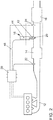
- Figure 1 shows an internal combustion engine 10 in the form of a gasoline engine charged with a turbocharger 32, with an intake duct 26 and with an exhaust duct 12.
- a compressor 28 In the intake duct 12, a compressor 28, a throttle valve 34 and a charge air cooler 36 are arranged.
- a turbine 38 of the turbocharger 32 is arranged in the exhaust gas channel 12 in the flow direction of an exhaust gas of the internal combustion engine 10 and drives the compressor 28 of the turbocharger 32 via a drive shaft 40.
- the compressor 28 can also be designed as a mechanically driven compressor or as an electrical compressor.
- a three-way catalytic converter 14 is arranged in the exhaust gas duct 12 downstream of the turbine 38.
- the three-way catalytic converter 14 is preferably arranged close to the engine in order to enable the three-way catalytic converter 14 to heat up quickly to a light-off temperature and thus to convert pollutants efficiently.
- An arrangement close to the engine is understood to mean an arrangement with an average exhaust gas travel path of at most 50 cm, in particular of at most 30 cm, after the outlet of the internal combustion engine 10.
- an introduction point 20 is provided for introducing secondary air into the exhaust gas duct 12.
- a secondary air supply 18 is connected to the inlet point 20 and comprises a secondary air valve 42 and a secondary air line 44, the secondary air line 44 connecting a section of the intake duct 26 upstream of the compressor 28 to the exhaust duct 12.
- a secondary air pump 48 is provided on the secondary air line 44, with which a pressure which is higher than the pressure in the exhaust gas duct 12 can be generated.
- the secondary air line 44 can also connect the environment to the exhaust duct 12.
- the secondary air line 44 opens at the secondary air valve 42 or the inlet point 20 downstream of the three-way catalytic converter 14 and upstream of a particle filter 16 into the exhaust gas duct 12.
- the three-way catalytic converter 14 is upstream a first lambda probe 22 is provided, with which the combustion air ratio ⁇ E of the internal combustion engine 10 is regulated.
- a second one Lambda probe 24 is provided, with which the amount of secondary air introduced into the exhaust gas duct 12 can be controlled by the secondary air valve 42.
- the first lambda probe 22, the second lambda probe 24 and the secondary air valve 42 are connected via signal lines 46 to a control unit 30 of the internal combustion engine 10 in order to enable regulation of the amount of secondary air blown into the exhaust gas duct 12.
- FIG. 2 the internal combustion engine 10 with the exhaust duct 12 is shown once again in simplified form.
- a first lambda probe 22 for controlling the combustion air ratio in the internal combustion engine 10 is arranged in the exhaust duct 12 downstream of the internal combustion engine 10 and upstream of the three-way catalytic converter 14. Downstream of the three-way catalytic converter is a control circuit for introducing secondary air into the exhaust gas duct 12, the control circuit comprising at least one secondary air supply 18 and a second lambda probe 24 arranged downstream of the inlet point 20 of the secondary air supply 18 and upstream of a particle filter 16.
- Soot generated during operation of the internal combustion engine is retained by the particle filter 16, the particle filter 16 loading with the soot particles of the internal combustion engine 10. If a defined threshold of the soot loading of the particle filter 16 is detected, which can be done, for example, by a differential pressure measurement before and after the particle filter 16 or by a model-based calculation, a regeneration method of the particle filter 16 is initiated.
- the exhaust gas temperature of the internal combustion engine 10 is first increased up to a regeneration temperature T R of at least 600 ° C. before entering the particle filter 16.
- the particle filter 16 preferably has a catalytic coating in order to oxidize unburned hydrocarbons, carbon monoxide and / or hydrogen exothermically on the surface of the particle filter 16.
- the particle filter 16 has a so-called "light-off temperature" of, for example, approximately 350 ° C. This ensures that unburned constituents of the fuel from the exhaust gas of the internal combustion engine 10 can be oxidized exothermically on the particle filter 16. If the light-off temperature of the particle filter 16 is present, the particle filter 16 is heated further at least up to the regeneration temperature T R. For this purpose, the internal combustion engine 10 is operated with a rich mixture, which preferably has a combustion air ratio ⁇ E of approximately 0.9. The unburned constituents of the mixture, in particular carbon monoxide, hydrocarbons and hydrogen, are introduced into the exhaust system 12 together with the combustion products.
- a so-called "light-off temperature” of, for example, approximately 350 ° C. This ensures that unburned constituents of the fuel from the exhaust gas of the internal combustion engine 10 can be oxidized exothermically on the particle filter 16. If the light-off temperature of the particle filter 16 is present, the particle filter 16 is heated further at least up to the regeneration
- the mixture air ratio ⁇ m from the combustion air ratio of the internal combustion engine 10 and the secondary air introduced is measured by the second lambda probe 24 downstream of the introduction point 20 and upstream of the particle filter 16.
- the system switches to a regeneration phase.
- ⁇ E stoichiometric combustion air ratio
- all pollutants in the exhaust gas of the internal combustion engine 10 can be completely converted on the three-way catalytic converter 14 during the regeneration phase.
- secondary air is also blown into the exhaust gas duct 12.
- FIG Figure 3 Such a regeneration of the particle filter 16 according to the invention is shown in FIG Figure 3 shown.
- the regeneration of the particle filter 16 is maintained until the particle filter 16 is completely regenerated, which can be determined via a differential pressure measurement or also via a calculation model for the soot entry and soot discharge.
- the secondary air supply 18 is switched off and no further oxygen is introduced into the exhaust duct 12 of the internal combustion engine 10.
- a third phase III which is also referred to as the regeneration phase
- a superstoichiometric, lean mixture air ratio ⁇ M > 1 occurs in the exhaust gas duct 12 downstream of the inlet point 20.
- the combustion air ratio ⁇ E is in Fig 3 shown with a solid line, the mixture air ratio ⁇ M downstream of the inlet point 20 with a dotted line and the introduced secondary air through secondary air supply 18 with a dashed line.
Landscapes
- Engineering & Computer Science (AREA)
- Chemical & Material Sciences (AREA)
- Combustion & Propulsion (AREA)
- Mechanical Engineering (AREA)
- General Engineering & Computer Science (AREA)
- Chemical Kinetics & Catalysis (AREA)
- Health & Medical Sciences (AREA)
- Toxicology (AREA)
- Materials Engineering (AREA)
- Exhaust Gas After Treatment (AREA)
- Processes For Solid Components From Exhaust (AREA)
Description
Die Erfindung betrifft ein Verfahren und eine Vorrichtung zur Abgasnachbehandlung eines Verbrennungsmotors.The invention relates to a method and a device for exhaust gas aftertreatment of an internal combustion engine.
Die kontinuierliche Verschärfung der Abgasgesetzgebung stellt hohe Anforderungen an die Fahrzeughersteller, welche durch entsprechende Maßnahmen zur Reduktion der motorischen Rohemissionen und durch eine entsprechende Abgasnachbehandlung gelöst werden. Mit Einführung der nächsten Gesetzgebungsstufe EU6 wird auch für Ottomotoren ein Grenzwert für eine Partikelanzahl vorgeschrieben. Dies kann dazu führen, dass bei einigen Modellen der Einsatz eines Ottopartikelfilters nötig sein kann. Im Fahrbetrieb wird ein solcher Ottopartikelfilter mit Ruß beladen. Damit der Abgasgegendruck nicht zu stark ansteigt, muss dieser Ottopartikelfilter kontinuierlich oder periodisch regeneriert werden. Um eine thermische Oxidation des im Ottopartikelfilter zurückgehaltenen Rußes mit Sauerstoff durchzuführen, ist ein hinreichend hohes Temperaturniveau in Verbindung mit gleichzeitig vorhandenem Sauerstoff in der Abgasanlage des Ottomotors notwendig. Dadurch kann der in dem Partikelfilter eingelagerte Ruß oxidiert werden. Da moderne Ottomotoren normalerweise ohne Sauerstoffüberschuss mit einem stöchiometrischen Verbrennungsluftverhältnis (λ=1) betrieben werden, sind dazu zusätzliche Maßnahmen erforderlich. Der Eintrag von Sauerstoff in den Abgaskanal erfolgt in der Regel über Schubphasen des Verbrennungsmotors, in denen kein Kraftstoff in die Brennräume eingespritzt wird. Alternativ dazu kommen als Maßnahmen beispielsweise eine zeitweise Magerverstellung des Ottomotors oder das Einblasen von Sekundärluft in die Abgasanlage infrage. Bevorzugt wird bislang eine Magerverstellung des Ottomotors angewandt, da dieses Verfahren ohne zusätzliche Bauteile auskommt und in den meisten Betriebspunkten des Ottomotors eine ausreichende Sauerstoffmenge liefern kann. Zur Überwachung und Steuerung der Regeneration ist zudem eine aufwendige Sensorik notwendig. Nachteilig an einer solchen Magerverstellung ist jedoch, dass gerade bei niedrigem Teillastbetrieb und bei Kurzstreckenfahrten nicht die zur Regeneration des Partikelfilters notwendige Regenerationstemperatur erreicht wird. Zudem können während der Magerverstellung des Motors Stickoxide nicht hinreichend durch den Drei-Wege-Katalysator konvertiert werden, da kein Reduktionsmittel für die Stickoxide vorliegt.The continual tightening of exhaust gas legislation places high demands on vehicle manufacturers, which can be solved by taking appropriate measures to reduce raw engine emissions and by treating the exhaust gas accordingly. With the introduction of the next legislative level EU6, a limit value for the number of particles is also prescribed for gasoline engines. This can mean that some models may require the use of a gasoline particulate filter. When driving, such a gasoline particulate filter is loaded with soot. So that the exhaust gas back pressure does not increase too much, this gasoline particle filter must be regenerated continuously or periodically. In order to carry out a thermal oxidation of the soot retained in the gasoline particle filter with oxygen, a sufficiently high temperature level in conjunction with oxygen present in the exhaust system of the gasoline engine is necessary. As a result, the soot stored in the particle filter can be oxidized. Since modern gasoline engines are normally operated without excess oxygen with a stoichiometric combustion air ratio (λ = 1), additional measures are required. Oxygen is usually introduced into the exhaust duct via the overrun phases of the internal combustion engine, in which no fuel is injected into the combustion chambers. As an alternative to this, measures may include, for example, temporarily adjusting the lean-burn engine of the gasoline engine or blowing secondary air into the exhaust system. Up to now, a lean-burn adjustment of the gasoline engine has been preferred, since this method does not require any additional components and can supply a sufficient amount of oxygen in most operating points of the gasoline engine. A complex sensor system is also required to monitor and control the regeneration. A disadvantage of such a lean adjustment, however, is that the regeneration temperature required for the regeneration of the particle filter is not reached, especially when the vehicle is operating at low partial load and on short journeys. In addition, nitrogen oxides cannot be adequately converted by the three-way catalytic converter during lean engine adjustment, since there is no reducing agent for the nitrogen oxides.
Aus der
Aus der
Aus der
Die
Aus der
Aus der
Die
Der Erfindung liegt nun die Aufgabe zugrunde, ein Verfahren und eine Vorrichtung bereitzustellen, mit denen sowohl ein hinreichend hohes Temperaturniveau für eine Regeneration des Partikelfilters erreicht wird, als auch während der Regeneration des Partikelfilters der Schadstoffausstoß möglichst gering gehalten wird, sodass die Regeneration des Partikelfilters im Wesentlichen emissionsneutral erfolgen kann.The invention is based on the object of providing a method and a device with which both a sufficiently high temperature level for a regeneration of the particle filter is achieved and also during the regeneration of the particle filter the pollutant emissions are kept as low as possible, so that the regeneration of the particle filter in Can be made essentially emission-neutral.
Die Aufgabe wird durch ein Verfahren zur Abgasnachbehandlung eines Verbrennungsmotors mit einem Abgaskanal sowie einem im Abgaskanal angeordneten Drei-Wege-Katalysator und einem stromabwärts des Drei-Wege-Katalysators angeordneten Partikelfilter gelöst, welches folgende Schritte umfasst:
- Betreiben des Verbrennungsmotors mit einem stöchiometrischen Verbrennungsluftverhältnis, wobei die bei der Verbrennung entstehenden Rußpartikel in dem Partikelfilter zurückgehalten werden,
- Ermittlung eines Beladungszustandes des Partikelfilters,
- Einleiten einer Regeneration des Partikelfilters, wenn bei der Ermittlung des Beladungszustandes die Notwendigkeit einer Regeneration des Partikelfilters erkannt wird,
- Anheben der Abgastemperatur durch einen Betrieb des Verbrennungsmotors mit einem unterstöchiometrischen, fetten Verbrennungsluftverhältnis und gleichzeitiger Einbringung von Sekundärluft in den Abgaskanal stromaufwärts des Partikelfilters, wobei die unverbrannten Kraftstoffkomponenten exotherm im Abgaskanal oder auf dem Partikelfilter mit der Sekundärluft umgesetzt werden,
- Regeneration des Partikelfilters, wobei der Verbrennungsmotor mit einem stöchiometrischen Verbrennungsluftverhältnis betrieben wird und Sekundärluft in den Abgaskanal eingebracht wird, wobei
- die Menge der in den Abgaskanal eingebrachten Sekundärluft über eine Lambdasonde stromabwärts einer Einleitstelle für die Sekundärluft und stromaufwärts des Partikelfilters geregelt wird.
- Operating the internal combustion engine with a stoichiometric combustion air ratio, the soot particles resulting from the combustion being retained in the particle filter,
- Determination of the loading condition of the particle filter,
- Initiating regeneration of the particle filter if the necessity of regeneration of the particle filter is recognized when determining the loading condition,
- Raising the exhaust gas temperature by operating the internal combustion engine with a substoichiometric, rich combustion air ratio and at the same time introducing secondary air into the exhaust gas duct upstream of the particle filter, the unburned fuel components being converted exothermally in the exhaust gas duct or on the particle filter with the secondary air,
- Regeneration of the particle filter, wherein the internal combustion engine is operated with a stoichiometric combustion air ratio and secondary air is introduced into the exhaust duct, wherein
- the amount of secondary air introduced into the exhaust duct is regulated via a lambda probe downstream of an inlet point for the secondary air and upstream of the particle filter.
Durch das erfindungsgemäße Verfahren kann der Partikelfilter auch bei niedriger Teillast oder im Kurzstreckenbetrieb auf eine Regenerationstemperatur aufgeheizt werden und darauffolgend regeneriert werden. Dabei kann durch die Lambdaregelung verhindert werden, dass zu viel Sauerstoff in den Abgaskanal gelangt und es so zu einem unkontrollierten Abbrand des Rußes und einer damit verbundenen thermischen Schädigung des Partikelfilters kommen kann. Die Nutzung der Lambdasonde anstelle von Druck- und/oder Temperatursensoren hat den Vorteil, dass direkt die Gemischgüte stromaufwärts des Partikelfilters im Abgaskanal bewertet werden kann.By means of the method according to the invention, the particle filter can be heated to a regeneration temperature even at low partial load or in short-distance operation and then regenerated. The lambda control can prevent too much oxygen from entering the exhaust gas duct, which can lead to uncontrolled burning of the soot and the associated thermal damage to the particle filter. The use of the lambda probe instead of pressure and / or temperature sensors has the advantage that the mixture quality upstream of the particle filter in the exhaust gas duct can be assessed directly.
Durch die in den abhängigen Ansprüchen aufgeführten Maßnahmen sind vorteilhafte Weiterbildungen und Verbesserungen des im unabhängigen Anspruch angegebenen Verfahrens zur Regeneration des Partikelfilters möglich.The measures listed in the dependent claims enable advantageous developments and improvements of the method for regeneration of the particle filter specified in the independent claim.
In bevorzugter Ausgestaltung der Erfindung ist vorgesehen, dass in der Heizphase durch die Sekundärlufteinbringung ein stöchiometrisches Mischungsluftverhältnis im Abgaskanal stromabwärts des Drei-Wege-Katalysators und stromaufwärts des Partikelfilters eingestellt wird. Dadurch kann die Sekundärluftmenge derart angepasst werden, dass während der Heizphase des Partikelfilters die unverbrannten Kraftstoffkomponenten vollständig im Abgaskanal und/oder auf dem Partikelfilter mit dem Sauerstoff aus der Sekundärluftversorgung umgesetzt werden, sodass es auch während der Heizphase nicht zu einem Abstieg der Emissionen an Kohlenmonoxid (CO) und unverbrannten Kohlenwasserstoffen (HC) kommt.In a preferred embodiment of the invention it is provided that a stoichiometric mixture air ratio in the exhaust gas duct downstream of the three-way catalytic converter and upstream of the particle filter is set in the heating phase by introducing the secondary air. This allows the amount of secondary air to be adjusted in such a way that during the heating phase of the particle filter the unburned fuel components are completely converted in the exhaust duct and / or on the particle filter with the oxygen from the secondary air supply, so that there is no decrease in emissions of carbon monoxide ( CO) and unburned hydrocarbons (HC) comes.
In einer bevorzugten Ausführungsform des Verfahrens ist vorgesehen, dass eine Temperatur des Partikelfilters ermittelt wird und in der Regenerationsphase die Temperatur oberhalb der Regenerationstemperatur des Partikelfilters gehalten wird. Dadurch kann der Partikelfilter in einem kontinuierlichen Prozess regeneriert werden, bis die komplette Rußbeladung des Partikelfilters oxidiert ist. Dadurch wird eine Restbeladung des Partikelfilters vermieden, welche zu häufigeren Regenerationszyklen und damit verbunden zu einem Mehrverbrauch des Verbrennungsmotors führt.In a preferred embodiment of the method it is provided that a temperature of the particle filter is determined and the temperature is kept above the regeneration temperature of the particle filter in the regeneration phase. As a result, the particle filter can be regenerated in a continuous process until the complete soot load on the particle filter is oxidized. This avoids residual loading of the particle filter, which leads to more frequent regeneration cycles and, as a result, to an increased consumption of the internal combustion engine.
In weiterer bevorzugter Ausgestaltung der Erfindung ist vorgesehen, dass bei Erreichen einer oberen Schwellentemperatur des Partikelfilters die Einbringung von Sekundärluft gestoppt wird. Durch einen Stopp der Sekundärlufteinbringung wird die exotherme Oxidation der im Partikelfilter zurückgehaltenen Rußpartikel gestoppt, sodass eine weitere Erwärmung des Partikelfilters vermieden werden kann. Somit kann die Lambdaregelung der Sekundärluft wirksam zum Bauteilschutz des Partikelfilters beitragen.In a further preferred embodiment of the invention it is provided that the introduction of secondary air is stopped when an upper threshold temperature of the particle filter is reached. By stopping the introduction of secondary air, the exothermic oxidation of the soot particles retained in the particle filter is stopped, so that further heating of the particle filter can be avoided. The lambda control of the secondary air can thus effectively contribute to the component protection of the particle filter.
Besonders bevorzugt ist dabei, wenn die in den Abgaskanal eindosierte Sekundärluftmenge in Abhängigkeit einer Temperaturänderung des Partikelfilters erhöht oder reduziert wird. Dabei wird die Sekundärluftmenge bei einem Anstieg der Partikelfiltertemperatur während der Regeneration des Partikelfilters so weit gedrosselt, bis der Temperaturanstieg beendet ist. Bei einem Abfallen der Partikelfiltertemperatur wird die Sekundärluftmenge während der Regeneration erhöht, um den Rußumsatz durch Oxidation auf dem Partikelfilter zu erhöhen und durch diese exotherme Reaktion die Temperatur des Partikelfilters zu stabilisieren oder zu erhöhen, damit die Temperatur des Partikelfilters während der Regeneration nicht unter die Regenerationstemperatur absinkt und keine weiteren Rußpartikel oxidiert werden können.It is particularly preferred if the amount of secondary air metered into the exhaust gas duct is increased or reduced as a function of a change in temperature of the particle filter. If the particle filter temperature rises during regeneration of the particle filter, the amount of secondary air is throttled until the temperature rise has ended. If the particle filter temperature drops, the amount of secondary air is increased during the regeneration in order to increase the soot conversion due to oxidation on the particle filter and, through this exothermic reaction, to stabilize or increase the temperature of the particle filter so that the temperature of the particle filter does not drop below the regeneration temperature during the regeneration sinks and no further soot particles can be oxidized.
Alternativ oder zusätzlich ist vorgesehen, dass die in den Abgaskanal eingebrachte Sekundärluftmenge mit zunehmender Regeneration des Partikelfilters und abnehmendem Beladungsgrad des Partikelfilters erhöht wird. Gerade bei stark beladenen Partikelfiltern und hohen Abgastemperaturen besteht die Gefahr, dass eine zu große Sauerstoffkonzentration im Abgaskanal zu einem unkontrollierten Rußabbrand auf dem Partikelfilter und einer damit verbundenen thermischen Schädigung des Partikelfilters führt. Je geringer die Beladung des Partikelfilters, desto geringer die weitere Oxidation von in dem Partikelfilter zurückgehaltenen Rußpartikeln. Damit die Reaktionsgeschwindigkeit zu Ende des Regenerationsvorgangs nicht zu stark abnimmt und die Temperatur am Partikelfilter unter die Regenerationstemperatur fällt, kann die Sauerstoffmenge durch zusätzliche Sekundärluft im Laufe der Regeneration erhöht werden.Alternatively or additionally, it is provided that the amount of secondary air introduced into the exhaust gas duct increases with increasing regeneration of the particle filter and decreasing degree of loading of the particle filter. Especially with heavily loaded particle filters and high exhaust gas temperatures, there is a risk that an excessively high oxygen concentration in the exhaust gas duct will lead to uncontrolled soot burn-off on the particle filter and the associated thermal damage to the particle filter. The lower the loading of the particle filter, the lower the further oxidation of soot particles retained in the particle filter. So that the reaction speed does not decrease too much at the end of the regeneration process and the temperature on the particle filter falls below the regeneration temperature, the amount of oxygen can be increased by additional secondary air during the regeneration.
Alternativ ist mit Vorteil vorgesehen, dass zur Regeneration des Partikelfilters mehrfach zwischen der Heizphase und der Regenerationsphase alternierend gewechselt wird. Somit kann sichergestellt werden, dass es einerseits während der Regeneration des Partikelfilters nicht zu einer Überhitzung und Schädigung des Bauteils kommt und der Regenerationsprozess nach Absinken der Temperatur unter die Regenerationstemperatur sooft wieder gestartet wird, bis eine vollständig Regeneration des Partikelfilters erreicht ist.Alternatively, it is advantageously provided that for the regeneration of the particle filter, there is a multiple alternation between the heating phase and the regeneration phase. This ensures that on the one hand there is no overheating and damage to the component during the regeneration of the particle filter and that the regeneration process is started again after the temperature has dropped below the regeneration temperature until a complete regeneration of the particle filter is achieved.
Gemäß einer Verbesserung des Verfahrens ist vorgesehen, dass die Temperatur während der Regeneration des Partikelfilters in einem Temperaturfenster zwischen der Regenerationstemperatur und einer oberen Schwellentemperatur gehalten wird. In diesem Temperaturfenster ist eine effiziente und schnelle Oxidation von im Partikelfilter zurückgehaltenen Rußpartikeln möglich, wobei die thermische Dauerhaltbarkeit des Partikelfilters nicht herabgesetzt wird und somit die Lebenszeit des Partikelfilters verkürzt wird.According to an improvement of the method, it is provided that the temperature is kept in a temperature window between the regeneration temperature and an upper threshold temperature during the regeneration of the particle filter. In this temperature window, an efficient and rapid oxidation of soot particles retained in the particle filter is possible, the thermal durability of the particle filter is not reduced and the life of the particle filter is thus shortened.
Besonders vorteilhaft ist dabei, wenn das Temperaturfenster in einem Bereich von 600°C bis 750°C liegt. Temperaturen oberhalb von 600°C haben sich bei bestehenden Partikelfiltern als effizient für die Oxidation der Rußpartikel herausgestellt. Dabei halten diese Partikelfilter Temperaturen von bis zu 750°C dauerhaft aus, ohne dass es zu einer Schädigung des Partikelfilters kommt.It is particularly advantageous if the temperature window is in a range from 600 ° C to 750 ° C. Temperatures above 600 ° C have been found to be efficient for the oxidation of the soot particles in existing particle filters. These particle filters can withstand temperatures of up to 750 ° C without causing damage to the particle filter.
Gemäß einer weiteren Verbesserung des Verfahrens ist vorgesehen, dass die Sekundärluftmenge derart eingeregelt wird, dass sich während der Regeneration des Partikelfilters ein Mischungsluftverhältnis stromauf des Partikelfilters von λM von 1,05 bis 1,4 einstellt. Somit ist eine Oxidation des im Partikelfilter zurückgehaltenen Rußes ohne einen unkontrollierten Rußabbrand möglich. Besonders vorteilhaft ist ein Bereich von 1,1 < λM < 1,25, da in diesem Bereich hinreichend große Umsatzraten bei der Rußoxidation erreicht werden, um eine schnelle Regeneration des Partikelfilters zu gewährleisten.According to a further improvement of the method, it is provided that the amount of secondary air is regulated in such a way that a mixture air ratio of λ M of 1.05 to 1.4 is established upstream of the particle filter during the regeneration of the particle filter. Oxidation of the soot retained in the particle filter is thus possible without uncontrolled soot burning. A range of 1.1 <λ M <1.25 is particularly advantageous, since sufficiently high conversion rates for soot oxidation are achieved in this range in order to ensure rapid regeneration of the particle filter.
In einer bevorzugten Weiterentwicklung des Verfahrens ist vorgesehen, dass die Sekundärluftmenge derart eingeregelt wird, dass sich stromab des Partikelfilters ein stöchiometrisches Abgas einstellt. Dabei wird durch die Sekundärlufteinbringung so viel Sauerstoff zur Verfügung gestellt, wie für eine stöchiometrische Oxidation der Rußpartikel notwendig ist. Somit kann die Oxidation der Rußpartikel im Wesentlichen emissionsneutral durchgeführt werden und es entstehen keine zusätzlichen, schädlichen Sekundäremissionen durch die Regeneration des Partikelfilters.In a preferred further development of the method it is provided that the amount of secondary air is regulated in such a way that a stoichiometric exhaust gas is established downstream of the particle filter. The secondary air supply provides as much oxygen as is necessary for stoichiometric oxidation of the soot particles. The oxidation of the soot particles can thus be carried out essentially in an emission-neutral manner and there are no additional, harmful secondary emissions due to the regeneration of the particle filter.
Gemäß einer vorteilhaften Ausführungsform des Verfahrens ist vorgesehen, dass die Heizphase erst dann beendet wird, wenn der Partikelfilter eine Temperatur erreicht, welche mindestens 30°, vorzugsweise mindestens 50° oberhalb der Regenerationstemperatur des Partikelfilters liegt. Somit ist gewährleistet, dass auch bei einer anfänglich geringen exothermen Oxidation der Rußpartikel die Temperatur des Partikelfilters nicht sofort wieder unter die Regenerationstemperatur abfällt und die Regeneration somit zum Stillstand kommt.According to an advantageous embodiment of the method, it is provided that the heating phase is only ended when the particle filter reaches a temperature which is at least 30 °, preferably at least 50 ° above the regeneration temperature of the particle filter. This ensures that, even with an initially low exothermic oxidation of the soot particles, the temperature of the particle filter does not immediately drop below the regeneration temperature and the regeneration thus comes to a standstill.
Gemäß einer bevorzugten Ausführungsform ist vorgesehen, dass an der Sekundärluftleitung eine Sekundärluftpumpe angeordnet ist. Durch die Sekundärluftpumpe kann auch bei niedriger Motorlast ein hinreichend großes Druckgefälle erzeugt werden, um Luft gegen den Abgasgegendruck in den Abgaskanal zu fördern. Alternativ kann bei Verbrennungsmotoren mit einem elektrisch angetriebenen Verdichter die Sekundärluft auch aus der Ansaugleitung stromab des Verdichters entnommen und in den Abgaskanal eingeleitet werden. Somit kann bei elektrisch aufgeladenen Motoren auf einen zusätzlichen Druckerzeuger, beispielsweise eine Sekundärluftpumpe, verzichtet werden und die Sekundärluft aus dem Ansaugtrakt des Verbrennungsmotors entnommen werden.According to a preferred embodiment, it is provided that a secondary air pump is arranged on the secondary air line. The secondary air pump can generate a sufficiently large pressure drop, even at low engine loads, to convey air against the exhaust gas back pressure into the exhaust duct. Alternatively, in internal combustion engines with an electrically driven compressor, the secondary air can also be taken from the intake line downstream of the compressor and introduced into the exhaust duct. In the case of electrically charged engines, an additional pressure generator, for example a secondary air pump, can thus be dispensed with and the secondary air can be removed from the intake tract of the internal combustion engine.
Erfindungsgemäß wird eine Vorrichtung zur Abgasnachbehandlung eines Verbrennungsmotors mit einem Abgaskanal, einem im Abgaskanal angeordneten Drei-Wege-Katalysator, einem im Abgaskanal stromabwärts des Drei-Wege-Katalysators angeordneten Partikelfilter, sowie mit einer Sekundärluftversorgung vorgeschlagen, wobei zwischen dem Drei-Wege-Katalysator und dem Partikelfilter eine Einleitstelle für die Sekundärluft aus der Sekundärluftversorgung vorgesehen ist, sowie mit einer ersten Lambdasonde, welche stromaufwärts des Drei-Wege-Katalysators angeordnet ist und einer zweiten Lambdasonde, welche stromabwärts der Einleitstelle und stromaufwärts des Partikelfilters angeordnet ist, wobei die Vorrichtung eingerichtet ist, um ein erfindungsgemäßes Verfahren durchzuführen.According to the invention, a device for exhaust gas aftertreatment of an internal combustion engine with an exhaust gas duct, a three-way catalytic converter arranged in the exhaust gas duct, a particle filter arranged in the exhaust gas duct downstream of the three-way catalytic converter, and with a secondary air supply is proposed, with between the three-way catalytic converter and an inlet point for the secondary air from the secondary air supply is provided for the particle filter, as well as with a first lambda probe which is arranged upstream of the three-way catalytic converter and a second lambda probe which is arranged downstream of the inlet point and upstream of the particle filter, the device being set up to carry out a method according to the invention.
Weitere bevorzugte Ausgestaltungen der Erfindung ergeben sich aus den übrigen, in den Unteransprüchen genannten Merkmalen.Further preferred embodiments of the invention result from the other features mentioned in the subclaims.
Die verschiedenen in dieser Anmeldung genannten Ausführungsformen der Erfindung sind, sofern im Einzelfall nicht anders ausgeführt, mit Vorteil miteinander kombinierbar.Unless otherwise stated in the individual case, the various embodiments of the invention mentioned in this application can advantageously be combined with one another.
Die Erfindung wird nachfolgend in Ausführungsbeispielen anhand der zugehörigen Zeichnungen erläutert. Es zeigen:
Figur 1- einen Verbrennungsmotor mit einem Drei-Wege-Katalysator sowie mit einem stromabwärts des Drei-Wege-Katalysators angeordneten Partikelfilter sowie einer Sekundärluftversorgung zur Durchführung eines erfindungsgemäßen Verfahrens,
Figur 2- den Abgaskanal eines Verbrennungsmotors sowie die Lambdasensorik zur Steuerung eines erfindungsgemäßen Verfahrens, und
- Figur 3
- ein Ablaufdiagramm eines erfindungsgemäßen Verfahrens zur Regeneration des Partikelfilters.
- Figure 1
- an internal combustion engine with a three-way catalytic converter and with a particle filter arranged downstream of the three-way catalytic converter and with a secondary air supply for carrying out a method according to the invention,
- Figure 2
- the exhaust duct of an internal combustion engine and the lambda sensor system for controlling a method according to the invention, and
- Figure 3
- a flowchart of a method according to the invention for the regeneration of the particle filter.
In Strömungsrichtung eines Abgases der Brennkraftmaschine 10 durch den Abgaskanal 12 ist stromab der Turbine 38 ein Drei-Wege-Katalysator 14 in dem Abgaskanal 12 angeordnet. Dabei ist der Drei-Wege-Katalysator 14 vorzugsweise motornah angeordnet, um ein schnelles Aufheizen des Drei-Wege-Katalysators 14 auf eine Light-Off-Temperatur und somit eine effiziente Konvertierung von Schadstoffen zu ermöglichen. Unter einer motornahen Anordnung wird dabei eine Anordnung mit einem mittleren Abgaslaufweg von höchstens 50 cm, insbesondere von höchstens 30 cm, nach dem Auslass des Verbrennungsmotors 10 verstanden. Stromabwärts des Drei-Wege-Katalysators 14 ist eine Einleitstelle 20 zur Sekundärlufteinbringung in den Abgaskanal 12 vorgesehen. An der Einleitstelle 20 ist eine Sekundärluftversorgung 18 angeschlossen, welche ein Sekundärluftventil 42 und eine Sekundärluftleitung 44 umfasst, wobei die Sekundärluftleitung 44 einen Abschnitt des Ansaugkanals 26 stromaufwärts des Verdichters 28 mit dem Abgaskanal 12 verbindet. Dabei ist an der Sekundärluftleitung 44 eine Sekundärluftpumpe 48 vorgesehen, mit der ein gegenüber dem Druck im Abgaskanal 12 erhöhter Druck erzeugt werden kann. Alternativ kann die Sekundärluftleitung 44 auch die Umgebung mit dem Abgaskanal 12 verbinden. Dabei mündet die Sekundärluftleitung 44 am Sekundärluftventil 42 beziehungsweise der Einleitstelle 20 stromabwärts des Drei-Wege-Katalysators 14 und stromaufwärts eines Partikelfilters 16 in den Abgaskanal 12. In Strömungsrichtung des Abgases der Brennkraftmaschine 10 durch den Abgaskanal 12 ist stromaufwärts des Drei-Wege-Katalysators 14 eine erste Lambdasonde 22 vorgesehen, mit der das Verbrennungsluftverhältnis λE des Verbrennungsmotors 10 geregelt wird. Stromabwärts der Einleitstelle 20 und stromaufwärts des Partikelfilters 16 ist eine zweite Lambdasonde 24 vorgesehen, mit welcher die in den Abgaskanal 12 eingebrachte Sekundärluftmenge durch das Sekundärluftventil 42 gesteuert werden kann. Dabei sind die erste Lambdasonde 22, die zweite Lambdasonde 24 sowie das Sekundärluftventil 42 über Signalleitungen 46 mit einem Steuergerät 30 des Verbrennungsmotors 10 verbunden, um eine Regelung der in den Abgaskanal 12 eingeblasenen Sekundärluftmenge zu ermöglichen.In the flow direction of an exhaust gas of the
In
Im Betrieb der Brennkraftmaschine entstehender Ruß wird durch den Partikelfilter 16 zurückgehalten, wobei sich der Partikelfilter 16 mit den Rußpartikeln des Verbrennungsmotors 10 belädt. Wird eine festgelegte Schwelle der Rußbeladung des Partikelfilters 16 detektiert, was beispielsweise durch eine Differenzdruckmessung vor und nach dem Partikelfilter 16 oder durch eine modellbasierte Berechnung erfolgen kann, wird ein Regenerationsverfahren des Partikelfilters 16 eingeleitet. Dazu wird zunächst die Abgastemperatur des Verbrennungsmotors 10 bis zu einer Regenerationstemperatur TR von mindestens 600°C vor Eintritt in den Partikelfilter 16 erhöht. Bevorzugt weist der Partikelfilter 16 eine katalytische Beschichtung auf, um unverbrannte Kohlenwasserstoffe, Kohlenmonoxid und/oder Wasserstoff exotherm auf der Oberfläche des Partikelfilters 16 zu oxidieren. Zunächst wird überprüft, ob der Partikelfilter 16 eine sogenannte "Light-Off-Temperatur" von beispielsweise ca. 350°C aufweist. Hierdurch ist sichergestellt, dass unverbrannte Bestandteile des Kraftstoffs aus dem Abgas der Brennkraftmaschine 10 auf dem Partikelfilter 16 exotherm oxidiert werden können. Liegt die Light-Off-Temperatur des Partikelfilters 16 vor, wird der Partikelfilter 16 mindestens bis zu der Regenerationstemperatur TR weiter aufgeheizt. Dazu wird die Brennkraftmaschine 10 mit einem fetten Gemisch betrieben, welches vorzugsweise ein Verbrennungsluftverhältnis λE von etwa 0,9 aufweist. Die unverbrannten Bestandteile des Gemischs, insbesondere Kohlenmonoxid, Kohlenwasserstoffe und Wasserstoff, werden zusammen mit den Verbrennungsprodukten in die Abgasanlage 12 eingeleitet. Durch einen Luftabgriff in dem Ansaugkanal 26 stromabwärts des Verdichters 28 und ein Einleiten dieser Luft über die Sekundärluftleitung 44 und das Sekundärluftventil 42 in den Abgaskanal 12, können diese unverbrannten Bestandteile des Kraftstoffs auf dem stromabliegenden Partikelfilter 16 exotherm umgesetzt werden. Durch die externe Luftzufuhr über die Sekundärluftversorgung 18 und den fetten Motorbetrieb können große Mengen an Abgasenthalpie in den Partikelfilter 16 eingebracht werden. Zur Überwachung beziehungsweise Regelung dieser Abgasenthalpie ist eine aufwendige Sensorik notwendig, welche einen Drucksensor, einen Temperatursensor sowie die zweite Lambdasonde 24 umfasst. Das Verbrennungsluftverhältnis λE der Brennkraftmaschine 10 kann vorgesteuert so eingestellt werden, dass sich die gewünschte Zieltemperatur einstellt. Gleichzeitig wird das Mischungsluftverhältnis λm aus Verbrennungsluftverhältnis der Brennkraftmaschine 10 und der eingebrachten Sekundärluft durch die zweite Lambdasonde 24 stromabwärts der Einleitstelle 20 und stromaufwärts des Partikelfilters 16 gemessen. Während der Heizphase des Partikelfilters 16 wird dieses Mischungsluftverhältnis auf λm = 1 eingeregelt, sodass die Emissionen auf der katalytischen Beschichtung des Partikelfilters 16 umgesetzt werden können und der Partikelfilter seine optimale Abgasreinigungswirkung erreichen kann.Soot generated during operation of the internal combustion engine is retained by the
Ist die Heizphase abgeschlossen und eine Temperatur oberhalb der Regenerationstemperatur TR des Partikelfilters 18 erreicht, wird auf eine Regenerationsphase umgestellt. Dazu wird die Brennkraftmaschine 10 wieder mit stöchiometrischem Verbrennungsluftverhältnis λE = 1 betrieben. Dadurch können alle Schadstoffe des Abgases der Brennkraftmaschine 10 während der Regenerationsphase auf dem Drei-Wege-Katalysator 14 vollständig umgesetzt werden. Um den Sauerstoff für die Regeneration des Partikelfilters 16 bereitzustellen, wird weiterhin Sekundärluft in den Abgaskanal 12 eingeblasen. Das gewünschte Mischungsluftverhältnis, beispielsweise λm = 1,1 kann durch entsprechende Regelung der Sekundärluft durch das Sekundärluftventil 42 eingestellt werden. Dadurch wird beispielsweise gewährleistet, dass die Umsatzrate des im Partikelfilter 16 zurückgehaltenen Rußes nicht zu hoch wird, was andernfalls zu einer thermischen Schädigung des Partikelfilters 16 führen könnte. Sinkt die Temperatur am Eintritt in den Partikelfilter 16 während der Regeneration ab, so wird die Menge an Sekundärluft erhöht, um die Umsatzraten des auf dem Partikelfilter zurückgehaltenen Rußes zu erhöhen und somit die Abgastemperatur TEG zu steigern. Eine solche erfindungsgemäße Regeneration des Partikelfilters 16 ist in
In einer ersten Phase I wird der Verbrennungsmotor 10 mit einem stöchiometrischen Verbrennungsluftverhältnis λE = 1 betrieben und die Rußpartikel in dem Partikelfilter 16 zurückgehalten. Dabei ist die Sekundärluftversorgung 18 abgeschaltet und es wird kein weiterer Sauerstoff in den Abgaskanal 12 des Verbrennungsmotors 10 eingebracht. In einer zweiten Phase II, welche auch als Heizphase bezeichnet wird, wird die externe Luftzufuhr durch die Sekundärluftversorgung 18 aktiviert und der Verbrennungsmotor 10 mit einem unterstöchiometrischen, fetten Verbrennungsluftverhältnis λE < 1 betrieben, sodass sich stromabwärts der Einleitstelle 20 ein stöchiometrisches Mischungsluftverhältnis λM = 1 einstellt.In a first phase I, the
In einer dritten Phase III, welche auch als Regenerationsphase bezeichnet wird, wird der Verbrennungsmotor 10 mit einem stöchiometrischen Verbrennungsluftverhältnis λE = 1 betrieben und die Sekundärlufteinbringung kontinuierlich erhöht, bis der Partikelfilter 16 vollständig regeneriert ist. Dabei stellt sich im Abgaskanal 12 stromabwärts der Einleitstelle 20 eine überstöchiometrisches, mageres Mischungsluftverhältnis λM > 1 ein. Ist der Partikelfilter 16 vollständig regeneriert, wird die Sekundärluftversorgung 18 wieder abgeschaltet und der Verbrennungsmotor 10 in einer erneuten Beladungsphase I wieder mit einem stöchiometrischen Verbrennungsluftverhältnis λE = 1 betrieben. Das Verbrennungsluftverhältnis λE ist in
- 1010th
- VerbrennungsmotorInternal combustion engine
- 1212th
- AbgaskanalExhaust duct
- 1414
- Drei-Wege-KatalysatorThree way catalyst
- 1616
- PartikelfilterParticle filter
- 1818th
- SekundärluftversorgungSecondary air supply
- 2020
- EinleitstelleDischarge point
- 2222
- erste Lambdasondefirst lambda sensor
- 2424th
- zweite Lambdasondesecond lambda sensor
- 2626
- AnsaugkanalIntake duct
- 2828
- Verdichtercompressor
- 3030th
- SteuergerätControl unit
- 3232
- Turboladerturbocharger
- 3434
- Drosselklappethrottle
- 3636
- LadeluftkühlerIntercooler
- 3838
- Turbineturbine
- 4040
- Antriebswelledrive shaft
- 4242
- SekundärluftventilSecondary air valve
- 4444
- SekundärluftleitungSecondary air line
- 4646
- SignalleitungSignal line
- 4848
- SekundärluftpumpeSecondary air pump
- λE λ E
- Verbrennungsluftverhältnis des VerbrennungsmotorsCombustion air ratio of the internal combustion engine
- λM λ M
- Mischungsluftverhältnis im Abgaskanal stromabwärts der SekundärlufteinbringungMixing air ratio in the exhaust duct downstream of the secondary air intake
- TEG T EG
- AbgastemperaturExhaust gas temperature
- TPF T PF
- Temperatur des PartikelfiltersParticle filter temperature
- TR T R
- Regenerationstemperatur des PartikelfiltersRegeneration temperature of the particle filter
- TSO T SO
- obere Schwellentemperaturupper threshold temperature
- ΔTPF ΔT PF
- Temperaturänderung des Partikelfilters während der RegenerationTemperature change of the particle filter during regeneration
Claims (15)
- Method for the exhaust-gas aftertreatment of an internal combustion engine (10) having an exhaust-gas duct (12) and a three-way catalytic converter (14) arranged in the exhaust-gas duct (12), a particle filter (16) arranged downstream of the three-way catalytic converter (14), and a secondary air supply (18), which method comprises the following steps:∘ operating the internal combustion engine (10) with a stoichiometric combustion air ratio (λE = 1), wherein the soot particles formed during the combustion are retained in the particle filter (16),∘ determining a loading state of the particle filter (16),∘ initiating a regeneration of the particle filter (16) if the need for a regeneration of the particle filter (16) is identified in the determination of the loading state,∘ raising the exhaust-gas temperature (TEG) in a heating phase by means of operation of the internal combustion engine (10) with a substoichiometric, rich combustion air ratio (λE < 1) and simultaneous introduction of secondary air into the exhaust-gas duct (12) upstream of the particle filter (16), wherein the unburned fuel components are exothermically converted in the exhaust-gas duct (12) or on the particle filter (16) with the secondary air until a regeneration temperature (TR) is attained;∘ regenerating the particle filter (16), wherein the internal combustion engine (10) is operated with a stoichiometric combustion air ratio (λE = 1) and secondary air is introduced into the exhaust-gas duct (12), such that superstoichiometric exhaust gas (λM > 1) is formed downstream of the introduction of secondary air, wherein∘ the quantity of secondary air introduced into the exhaust-gas channel (12) is controlled in closed-loop fashion by means of a lambda probe (24) downstream of an introduction point (20) for the secondary air and upstream of the particle filter (16).
- Method according to Claim 1, characterized in that, in the heating phase, by means of the introduction of secondary air, a stoichiometric mixture air ratio (AM = 1) is realized in the exhaust-gas duct (12) downstream of the three-way catalytic converter (14) and upstream of the particle filter (16).
- Method according to Claim 1 or 2, characterized in that a temperature (TPF) of the particle filter (16) is determined and, in the regeneration phase, the temperature (TPF) is kept above the regeneration temperature (TR) of the particle filter (16).
- Method according to any of Claims 1 to 3, characterized in that, in the event of an upper threshold temperature (TSO) being reached, the introduction of secondary air is stopped.
- Method according to Claim 3 or 4, characterized in that the secondary air quantity metered into the exhaust-gas duct (12) is increased or reduced in a manner dependent on a temperature change (ΔTPF) of the particle filter (16).
- Method according to any of Claims 1 to 5, characterized in that the secondary air quantity metered into the exhaust-gas duct (12) is increased with progressive regeneration of the particle filter (16).
- Method according to any of Claims 1 to 6, characterized in that, for the regeneration of the particle filter (16), repeated alternating switching between the heating phase and the regeneration phase is performed.
- Method according to any of Claims 1 to 7, characterized in that the temperature of the particle filter is, during the regeneration, kept in a temperature window between the regeneration temperature (TR) and an upper threshold temperature (TSO).
- Method according to Claim 8, characterized in that the temperature window lies in a range from 600°C to 750°C.
- Method according to any of Claims 1 to 9, characterized in that the secondary air quantity is adjusted by closed-loop control such that, during the regeneration of the particle filter (16), a mixture air ratio (λM) upstream of the particle filter (16) of 1.05 to 1.4, preferably of 1.1 to 1.25, is realized.
- Method according to any of Claims 1 to 10, characterized in that the secondary air quantity is adjusted by closed-loop control such that stoichiometric exhaust gas is realized downstream of the particle filter (16) .
- Method according to any of Claims 1 to 11, characterized in that the heating phase is ended only when the particle filter (16) reaches a temperature which lies at least 30°C, preferably at least 50°C, above the regeneration temperature (TR) of the particle filter (16) .
- Method according to any of Claims 1 to 12, characterized in that the secondary air is extracted from an intake duct (26) of the internal combustion engine (10) downstream of a compressor (28) and introduced into the exhaust-gas duct (12).
- Control unit (30) for an internal combustion engine (10), which control unit has a computer-readable program algorithm for controlling the method according to any of Claims 1 to 13.
- Device for the exhaust-gas aftertreatment of an internal combustion engine (10) having an exhaust-gas duct (12), having a three-way catalytic converter (14) arranged in the exhaust-gas duct and having a particle filter (16) arranged in the exhaust-gas duct (12) downstream of the three-way catalytic converter (14) and having a secondary air supply (18), wherein an introduction point (20) for the secondary air from the secondary air source (18) is provided between the three-way catalytic converter (14) and the particle filter (16), and having a first lambda probe (22), which is arranged upstream of the three-way catalytic converter (14), and a second lambda probe (24), which is arranged downstream of the introduction point (20) and upstream of the particle filter (16), wherein the device is configured to carry out a method according to any of Claims 1 to 13.
Applications Claiming Priority (2)
| Application Number | Priority Date | Filing Date | Title |
|---|---|---|---|
| DE102016211274.0A DE102016211274A1 (en) | 2016-06-23 | 2016-06-23 | Method and device for exhaust aftertreatment of an internal combustion engine |
| PCT/EP2017/064874 WO2017220460A1 (en) | 2016-06-23 | 2017-06-19 | Method and device for the exhaust gas aftertreatment of an internal combustion engine |
Publications (2)
| Publication Number | Publication Date |
|---|---|
| EP3475543A1 EP3475543A1 (en) | 2019-05-01 |
| EP3475543B1 true EP3475543B1 (en) | 2020-08-05 |
Family
ID=59091503
Family Applications (1)
| Application Number | Title | Priority Date | Filing Date |
|---|---|---|---|
| EP17731538.9A Active EP3475543B1 (en) | 2016-06-23 | 2017-06-19 | Method and device for the exhaust gas aftertreatment of an internal combustion engine |
Country Status (6)
| Country | Link |
|---|---|
| US (1) | US20190203629A1 (en) |
| EP (1) | EP3475543B1 (en) |
| KR (1) | KR102159068B1 (en) |
| CN (1) | CN109477414B (en) |
| DE (1) | DE102016211274A1 (en) |
| WO (1) | WO2017220460A1 (en) |
Families Citing this family (14)
| Publication number | Priority date | Publication date | Assignee | Title |
|---|---|---|---|---|
| DE102018100240A1 (en) | 2018-01-08 | 2019-07-11 | Volkswagen Aktiengesellschaft | Exhaust gas aftertreatment system and method for exhaust aftertreatment of an internal combustion engine |
| AT521759B1 (en) * | 2018-10-05 | 2021-12-15 | Avl List Gmbh | Method and arrangement of a gasoline engine with an improved exhaust aftertreatment through a regeneration strategy |
| JP7119874B2 (en) * | 2018-10-10 | 2022-08-17 | トヨタ自動車株式会社 | Control device for internal combustion engine, internal combustion engine and vehicle |
| DE102018218051A1 (en) * | 2018-10-22 | 2020-04-23 | Robert Bosch Gmbh | Method and control device for operating an internal combustion engine having a first exhaust gas cleaning component and a second exhaust gas cleaning component |
| DE102018222587A1 (en) * | 2018-12-20 | 2020-06-25 | Robert Bosch Gmbh | Internal combustion engine with an air injection in front of a particle filter |
| DE102019100752A1 (en) | 2019-01-14 | 2020-07-16 | Volkswagen Ag | Regeneration air system for an exhaust gas aftertreatment system of an internal combustion engine and method for exhaust gas aftertreatment |
| DE102019103001A1 (en) * | 2019-02-07 | 2020-08-13 | Bayerische Motoren Werke Aktiengesellschaft | Particulate filter assembly for motor vehicles, motor vehicles and methods for regenerating a particle filter |
| EP3696394B1 (en) * | 2019-02-13 | 2023-08-16 | FCA Italy S.p.A. | System and method for controlling the emissions of a spark-ignition internal combustion engine of a motor-vehicle |
| DE102019005155A1 (en) * | 2019-07-24 | 2021-01-28 | Daimler Ag | Internal combustion engine for a motor vehicle, in particular for a motor vehicle, and a method for operating such an internal combustion engine |
| US11073059B2 (en) * | 2019-08-22 | 2021-07-27 | Ford Global Technologies, Llc | Method and system for exhaust air injection |
| CN110939498B (en) * | 2019-12-16 | 2021-04-27 | 东风汽车集团有限公司 | Supercharged gasoline hybrid vehicle type GPF regeneration device and control method |
| CN113550813A (en) * | 2020-04-26 | 2021-10-26 | 长城汽车股份有限公司 | Nitrogen oxide conversion method, device and vehicle |
| GB2607100A (en) * | 2021-05-28 | 2022-11-30 | Jaguar Land Rover Ltd | Exhaust system, controller and method for an internal combustion engine |
| DE102021004774A1 (en) * | 2021-09-21 | 2023-04-06 | Mercedes-Benz Group AG | Internal combustion engine for a motor vehicle, in particular for a motor vehicle |
Family Cites Families (17)
| Publication number | Priority date | Publication date | Assignee | Title |
|---|---|---|---|---|
| JPS5977021A (en) * | 1982-10-23 | 1984-05-02 | Mitsubishi Motors Corp | Exhaust emission control device for diesel engine |
| US4589254A (en) * | 1983-07-15 | 1986-05-20 | Mitsubishi Jidosha Kogyo Kabushiki Kaisha | Regenerator for diesel particulate filter |
| JP3146870B2 (en) * | 1994-08-25 | 2001-03-19 | 三菱自動車工業株式会社 | Particulate filter regeneration device |
| US6546721B2 (en) * | 2000-04-18 | 2003-04-15 | Toyota Jidosha Kabushiki Kaisha | Exhaust gas purification device |
| DE102005062398B4 (en) * | 2005-12-23 | 2016-02-04 | Volkswagen Ag | Regenerating a particulate filter with an oxidation catalytic coating |
| JP2010013974A (en) | 2008-07-02 | 2010-01-21 | Toyota Motor Corp | Filter regenerating system and filter regenerating method |
| DE102009043087B4 (en) * | 2009-09-25 | 2023-08-03 | Volkswagen Ag | Internal combustion engine with secondary air supply and a method for operating this |
| US8359840B2 (en) * | 2009-09-29 | 2013-01-29 | Ford Global Technologies, Llc | Method for adjusting boost pressure while regenerating a particulate filter for a direct injection engine |
| US8327628B2 (en) | 2009-09-29 | 2012-12-11 | Ford Global Technologies, Llc | Gasoline particulate filter regeneration and diagnostics |
| US20110225969A1 (en) * | 2010-03-19 | 2011-09-22 | Gm Global Technology Operations, Inc. | Compressor bypass to exhaust for particulate trap regeneration |
| DE102010044102A1 (en) | 2010-11-18 | 2012-05-24 | Ford Global Technologies, Llc | Exhaust system for internal combustion engines with particle filter |
| DE102011002438A1 (en) | 2011-01-04 | 2012-07-05 | Robert Bosch Gmbh | Method for determining loading of particulate filter in exhaust gas passage of combustion engine e.g. petrol engine, involves utilizing secondary air pump as pressure increasing device |
| KR101326829B1 (en) * | 2011-10-13 | 2013-11-11 | 현대자동차주식회사 | System and method for regenerating a gasoline particulate filter |
| DE102013220899A1 (en) | 2013-10-15 | 2015-04-16 | Continental Automotive Gmbh | Regeneration of a particulate filter of an exhaust aftertreatment system for an internal combustion engine with a lambda control |
| JP6237464B2 (en) | 2014-05-22 | 2017-11-29 | 株式会社デンソー | Exhaust gas purification control device for internal combustion engine |
| CN104454084B (en) * | 2014-09-03 | 2017-11-28 | 内蒙古农业大学职业技术学院 | A kind of pulse cleaning eddy flow trap |
| DE102015215373A1 (en) * | 2015-08-12 | 2017-02-16 | Volkswagen Ag | A method for the regeneration of exhaust aftertreatment components of an internal combustion engine and exhaust aftertreatment device for an internal combustion engine |
-
2016
- 2016-06-23 DE DE102016211274.0A patent/DE102016211274A1/en not_active Withdrawn
-
2017
- 2017-06-19 US US16/312,044 patent/US20190203629A1/en not_active Abandoned
- 2017-06-19 EP EP17731538.9A patent/EP3475543B1/en active Active
- 2017-06-19 WO PCT/EP2017/064874 patent/WO2017220460A1/en unknown
- 2017-06-19 KR KR1020197001745A patent/KR102159068B1/en active IP Right Grant
- 2017-06-19 CN CN201780043872.8A patent/CN109477414B/en active Active
Non-Patent Citations (1)
| Title |
|---|
| None * |
Also Published As
| Publication number | Publication date |
|---|---|
| DE102016211274A1 (en) | 2017-12-28 |
| CN109477414A (en) | 2019-03-15 |
| EP3475543A1 (en) | 2019-05-01 |
| CN109477414B (en) | 2021-04-09 |
| KR102159068B1 (en) | 2020-09-24 |
| US20190203629A1 (en) | 2019-07-04 |
| KR20190021348A (en) | 2019-03-05 |
| WO2017220460A1 (en) | 2017-12-28 |
Similar Documents
| Publication | Publication Date | Title |
|---|---|---|
| EP3475543B1 (en) | Method and device for the exhaust gas aftertreatment of an internal combustion engine | |
| EP3115566B1 (en) | Method for exhaust gas after-treatment of an internal combustion engine | |
| DE102015212514B4 (en) | Method for exhaust gas aftertreatment and device for cleaning the exhaust gas of an internal combustion engine | |
| EP1121513B1 (en) | Method for reducing nitrogen oxide in the exhaust gases of an internal combustion engine operated with a lean mixture | |
| EP3642460A1 (en) | System and method for exhaust-gas aftertreatment of an internal combustion engine | |
| EP3344863B1 (en) | Method and apparatus for exhaust gas treatment of an internal combustion engine | |
| EP3921520B1 (en) | Exhaust gas aftertreatment system, and method for the exhaust gas aftertreatment of an internal combustion engine | |
| EP2376749B1 (en) | Method for operating for exhaust gas after-treatment components and exhaust gas after-treatment device | |
| DE102011100677A1 (en) | Operating method for a motor vehicle diesel engine | |
| EP2788598B1 (en) | Method and device for operating an internal combustion engine comprising an exhaust gas cleaning unit | |
| EP2699771A1 (en) | Operating method for a motor vehicle diesel engine having an exhaust emission control system | |
| DE102015215373A1 (en) | A method for the regeneration of exhaust aftertreatment components of an internal combustion engine and exhaust aftertreatment device for an internal combustion engine | |
| DE102016110632B4 (en) | Process for regenerating a particulate filter | |
| EP3523515B1 (en) | Method for regenerating a particle filter, and motor vehicle having a particle filter | |
| DE102006007122A1 (en) | Operating process for internal combustion engine involves reporting suitable combinations of engine operating values for preset nitrogen oxide emission value | |
| WO2018134151A1 (en) | Regeneration of a particulate filter or four-way catalytic converter in an exhaust system of an internal combustion engine | |
| EP3404228B1 (en) | Regeneration of a particle filter or four-way catalytic converter in the exhaust system of a combustion engine | |
| DE102018006318A1 (en) | An exhaust purification device of an engine, a vehicle engine including an exhaust purification device, and a method of controlling an engine | |
| EP3599353B1 (en) | Method for regenerating a particle filter in the exhaust system of a gasoline engine | |
| AT521759B1 (en) | Method and arrangement of a gasoline engine with an improved exhaust aftertreatment through a regeneration strategy | |
| DE10252343B4 (en) | Emission control system and method for an internal combustion engine | |
| EP3667056B1 (en) | Exhaust gas aftertreatment of an internal combustion engine | |
| EP3584418B1 (en) | Waste gas treatment system and method for regenerating a particle filter | |
| EP4095364B1 (en) | Method for operating a combustion engine | |
| EP2294292B1 (en) | Method and device for operating an exhaust gas after-treatment system |
Legal Events
| Date | Code | Title | Description |
|---|---|---|---|
| STAA | Information on the status of an ep patent application or granted ep patent |
Free format text: STATUS: UNKNOWN |
|
| STAA | Information on the status of an ep patent application or granted ep patent |
Free format text: STATUS: THE INTERNATIONAL PUBLICATION HAS BEEN MADE |
|
| PUAI | Public reference made under article 153(3) epc to a published international application that has entered the european phase |
Free format text: ORIGINAL CODE: 0009012 |
|
| STAA | Information on the status of an ep patent application or granted ep patent |
Free format text: STATUS: REQUEST FOR EXAMINATION WAS MADE |
|
| 17P | Request for examination filed |
Effective date: 20190123 |
|
| AK | Designated contracting states |
Kind code of ref document: A1 Designated state(s): AL AT BE BG CH CY CZ DE DK EE ES FI FR GB GR HR HU IE IS IT LI LT LU LV MC MK MT NL NO PL PT RO RS SE SI SK SM TR |
|
| AX | Request for extension of the european patent |
Extension state: BA ME |
|
| DAV | Request for validation of the european patent (deleted) | ||
| DAX | Request for extension of the european patent (deleted) | ||
| GRAP | Despatch of communication of intention to grant a patent |
Free format text: ORIGINAL CODE: EPIDOSNIGR1 |
|
| STAA | Information on the status of an ep patent application or granted ep patent |
Free format text: STATUS: GRANT OF PATENT IS INTENDED |
|
| INTG | Intention to grant announced |
Effective date: 20200211 |
|
| GRAS | Grant fee paid |
Free format text: ORIGINAL CODE: EPIDOSNIGR3 |
|
| GRAA | (expected) grant |
Free format text: ORIGINAL CODE: 0009210 |
|
| STAA | Information on the status of an ep patent application or granted ep patent |
Free format text: STATUS: THE PATENT HAS BEEN GRANTED |
|
| AK | Designated contracting states |
Kind code of ref document: B1 Designated state(s): AL AT BE BG CH CY CZ DE DK EE ES FI FR GB GR HR HU IE IS IT LI LT LU LV MC MK MT NL NO PL PT RO RS SE SI SK SM TR |
|
| REG | Reference to a national code |
Ref country code: GB Ref legal event code: FG4D Free format text: NOT ENGLISH |
|
| REG | Reference to a national code |
Ref country code: CH Ref legal event code: EP |
|
| REG | Reference to a national code |
Ref country code: AT Ref legal event code: REF Ref document number: 1299000 Country of ref document: AT Kind code of ref document: T Effective date: 20200815 |
|
| REG | Reference to a national code |
Ref country code: DE Ref legal event code: R096 Ref document number: 502017006593 Country of ref document: DE |
|
| REG | Reference to a national code |
Ref country code: IE Ref legal event code: FG4D Free format text: LANGUAGE OF EP DOCUMENT: GERMAN |
|
| REG | Reference to a national code |
Ref country code: LT Ref legal event code: MG4D |
|
| REG | Reference to a national code |
Ref country code: NL Ref legal event code: MP Effective date: 20200805 |
|
| PG25 | Lapsed in a contracting state [announced via postgrant information from national office to epo] |
Ref country code: PT Free format text: LAPSE BECAUSE OF FAILURE TO SUBMIT A TRANSLATION OF THE DESCRIPTION OR TO PAY THE FEE WITHIN THE PRESCRIBED TIME-LIMIT Effective date: 20201207 Ref country code: GR Free format text: LAPSE BECAUSE OF FAILURE TO SUBMIT A TRANSLATION OF THE DESCRIPTION OR TO PAY THE FEE WITHIN THE PRESCRIBED TIME-LIMIT Effective date: 20201106 Ref country code: SE Free format text: LAPSE BECAUSE OF FAILURE TO SUBMIT A TRANSLATION OF THE DESCRIPTION OR TO PAY THE FEE WITHIN THE PRESCRIBED TIME-LIMIT Effective date: 20200805 Ref country code: NO Free format text: LAPSE BECAUSE OF FAILURE TO SUBMIT A TRANSLATION OF THE DESCRIPTION OR TO PAY THE FEE WITHIN THE PRESCRIBED TIME-LIMIT Effective date: 20201105 Ref country code: FI Free format text: LAPSE BECAUSE OF FAILURE TO SUBMIT A TRANSLATION OF THE DESCRIPTION OR TO PAY THE FEE WITHIN THE PRESCRIBED TIME-LIMIT Effective date: 20200805 Ref country code: HR Free format text: LAPSE BECAUSE OF FAILURE TO SUBMIT A TRANSLATION OF THE DESCRIPTION OR TO PAY THE FEE WITHIN THE PRESCRIBED TIME-LIMIT Effective date: 20200805 Ref country code: BG Free format text: LAPSE BECAUSE OF FAILURE TO SUBMIT A TRANSLATION OF THE DESCRIPTION OR TO PAY THE FEE WITHIN THE PRESCRIBED TIME-LIMIT Effective date: 20201105 Ref country code: ES Free format text: LAPSE BECAUSE OF FAILURE TO SUBMIT A TRANSLATION OF THE DESCRIPTION OR TO PAY THE FEE WITHIN THE PRESCRIBED TIME-LIMIT Effective date: 20200805 Ref country code: LT Free format text: LAPSE BECAUSE OF FAILURE TO SUBMIT A TRANSLATION OF THE DESCRIPTION OR TO PAY THE FEE WITHIN THE PRESCRIBED TIME-LIMIT Effective date: 20200805 |
|
| PG25 | Lapsed in a contracting state [announced via postgrant information from national office to epo] |
Ref country code: PL Free format text: LAPSE BECAUSE OF FAILURE TO SUBMIT A TRANSLATION OF THE DESCRIPTION OR TO PAY THE FEE WITHIN THE PRESCRIBED TIME-LIMIT Effective date: 20200805 Ref country code: RS Free format text: LAPSE BECAUSE OF FAILURE TO SUBMIT A TRANSLATION OF THE DESCRIPTION OR TO PAY THE FEE WITHIN THE PRESCRIBED TIME-LIMIT Effective date: 20200805 Ref country code: LV Free format text: LAPSE BECAUSE OF FAILURE TO SUBMIT A TRANSLATION OF THE DESCRIPTION OR TO PAY THE FEE WITHIN THE PRESCRIBED TIME-LIMIT Effective date: 20200805 Ref country code: NL Free format text: LAPSE BECAUSE OF FAILURE TO SUBMIT A TRANSLATION OF THE DESCRIPTION OR TO PAY THE FEE WITHIN THE PRESCRIBED TIME-LIMIT Effective date: 20200805 Ref country code: IS Free format text: LAPSE BECAUSE OF FAILURE TO SUBMIT A TRANSLATION OF THE DESCRIPTION OR TO PAY THE FEE WITHIN THE PRESCRIBED TIME-LIMIT Effective date: 20201205 |
|
| PG25 | Lapsed in a contracting state [announced via postgrant information from national office to epo] |
Ref country code: EE Free format text: LAPSE BECAUSE OF FAILURE TO SUBMIT A TRANSLATION OF THE DESCRIPTION OR TO PAY THE FEE WITHIN THE PRESCRIBED TIME-LIMIT Effective date: 20200805 Ref country code: SM Free format text: LAPSE BECAUSE OF FAILURE TO SUBMIT A TRANSLATION OF THE DESCRIPTION OR TO PAY THE FEE WITHIN THE PRESCRIBED TIME-LIMIT Effective date: 20200805 Ref country code: DK Free format text: LAPSE BECAUSE OF FAILURE TO SUBMIT A TRANSLATION OF THE DESCRIPTION OR TO PAY THE FEE WITHIN THE PRESCRIBED TIME-LIMIT Effective date: 20200805 Ref country code: CZ Free format text: LAPSE BECAUSE OF FAILURE TO SUBMIT A TRANSLATION OF THE DESCRIPTION OR TO PAY THE FEE WITHIN THE PRESCRIBED TIME-LIMIT Effective date: 20200805 Ref country code: RO Free format text: LAPSE BECAUSE OF FAILURE TO SUBMIT A TRANSLATION OF THE DESCRIPTION OR TO PAY THE FEE WITHIN THE PRESCRIBED TIME-LIMIT Effective date: 20200805 |
|
| REG | Reference to a national code |
Ref country code: DE Ref legal event code: R097 Ref document number: 502017006593 Country of ref document: DE |
|
| PG25 | Lapsed in a contracting state [announced via postgrant information from national office to epo] |
Ref country code: AL Free format text: LAPSE BECAUSE OF FAILURE TO SUBMIT A TRANSLATION OF THE DESCRIPTION OR TO PAY THE FEE WITHIN THE PRESCRIBED TIME-LIMIT Effective date: 20200805 |
|
| PLBE | No opposition filed within time limit |
Free format text: ORIGINAL CODE: 0009261 |
|
| STAA | Information on the status of an ep patent application or granted ep patent |
Free format text: STATUS: NO OPPOSITION FILED WITHIN TIME LIMIT |
|
| PG25 | Lapsed in a contracting state [announced via postgrant information from national office to epo] |
Ref country code: SK Free format text: LAPSE BECAUSE OF FAILURE TO SUBMIT A TRANSLATION OF THE DESCRIPTION OR TO PAY THE FEE WITHIN THE PRESCRIBED TIME-LIMIT Effective date: 20200805 |
|
| 26N | No opposition filed |
Effective date: 20210507 |
|
| PG25 | Lapsed in a contracting state [announced via postgrant information from national office to epo] |
Ref country code: IT Free format text: LAPSE BECAUSE OF FAILURE TO SUBMIT A TRANSLATION OF THE DESCRIPTION OR TO PAY THE FEE WITHIN THE PRESCRIBED TIME-LIMIT Effective date: 20200805 |
|
| PG25 | Lapsed in a contracting state [announced via postgrant information from national office to epo] |
Ref country code: SI Free format text: LAPSE BECAUSE OF FAILURE TO SUBMIT A TRANSLATION OF THE DESCRIPTION OR TO PAY THE FEE WITHIN THE PRESCRIBED TIME-LIMIT Effective date: 20200805 |
|
| PG25 | Lapsed in a contracting state [announced via postgrant information from national office to epo] |
Ref country code: MC Free format text: LAPSE BECAUSE OF FAILURE TO SUBMIT A TRANSLATION OF THE DESCRIPTION OR TO PAY THE FEE WITHIN THE PRESCRIBED TIME-LIMIT Effective date: 20200805 |
|
| REG | Reference to a national code |
Ref country code: CH Ref legal event code: PL |
|
| REG | Reference to a national code |
Ref country code: BE Ref legal event code: MM Effective date: 20210630 |
|
| PG25 | Lapsed in a contracting state [announced via postgrant information from national office to epo] |
Ref country code: LU Free format text: LAPSE BECAUSE OF NON-PAYMENT OF DUE FEES Effective date: 20210619 |
|
| PG25 | Lapsed in a contracting state [announced via postgrant information from national office to epo] |
Ref country code: LI Free format text: LAPSE BECAUSE OF NON-PAYMENT OF DUE FEES Effective date: 20210630 Ref country code: IE Free format text: LAPSE BECAUSE OF NON-PAYMENT OF DUE FEES Effective date: 20210619 Ref country code: CH Free format text: LAPSE BECAUSE OF NON-PAYMENT OF DUE FEES Effective date: 20210630 |
|
| PG25 | Lapsed in a contracting state [announced via postgrant information from national office to epo] |
Ref country code: BE Free format text: LAPSE BECAUSE OF NON-PAYMENT OF DUE FEES Effective date: 20210630 |
|
| P01 | Opt-out of the competence of the unified patent court (upc) registered |
Effective date: 20230523 |
|
| PG25 | Lapsed in a contracting state [announced via postgrant information from national office to epo] |
Ref country code: CY Free format text: LAPSE BECAUSE OF FAILURE TO SUBMIT A TRANSLATION OF THE DESCRIPTION OR TO PAY THE FEE WITHIN THE PRESCRIBED TIME-LIMIT Effective date: 20200805 |
|
| PG25 | Lapsed in a contracting state [announced via postgrant information from national office to epo] |
Ref country code: HU Free format text: LAPSE BECAUSE OF FAILURE TO SUBMIT A TRANSLATION OF THE DESCRIPTION OR TO PAY THE FEE WITHIN THE PRESCRIBED TIME-LIMIT; INVALID AB INITIO Effective date: 20170619 |
|
| PGFP | Annual fee paid to national office [announced via postgrant information from national office to epo] |
Ref country code: FR Payment date: 20230622 Year of fee payment: 7 Ref country code: DE Payment date: 20230630 Year of fee payment: 7 |
|
| REG | Reference to a national code |
Ref country code: AT Ref legal event code: MM01 Ref document number: 1299000 Country of ref document: AT Kind code of ref document: T Effective date: 20220619 |
|
| PG25 | Lapsed in a contracting state [announced via postgrant information from national office to epo] |
Ref country code: AT Free format text: LAPSE BECAUSE OF NON-PAYMENT OF DUE FEES Effective date: 20220619 |
|
| PGFP | Annual fee paid to national office [announced via postgrant information from national office to epo] |
Ref country code: GB Payment date: 20230620 Year of fee payment: 7 |
|
| PG25 | Lapsed in a contracting state [announced via postgrant information from national office to epo] |
Ref country code: MK Free format text: LAPSE BECAUSE OF FAILURE TO SUBMIT A TRANSLATION OF THE DESCRIPTION OR TO PAY THE FEE WITHIN THE PRESCRIBED TIME-LIMIT Effective date: 20200805 |